WO2019026554A1 - ガラスフィルムの製造方法 - Google Patents
ガラスフィルムの製造方法 Download PDFInfo
- Publication number
- WO2019026554A1 WO2019026554A1 PCT/JP2018/025883 JP2018025883W WO2019026554A1 WO 2019026554 A1 WO2019026554 A1 WO 2019026554A1 JP 2018025883 W JP2018025883 W JP 2018025883W WO 2019026554 A1 WO2019026554 A1 WO 2019026554A1
- Authority
- WO
- WIPO (PCT)
- Prior art keywords
- glass film
- rod
- glass
- plate
- conveying
- Prior art date
- Legal status (The legal status is an assumption and is not a legal conclusion. Google has not performed a legal analysis and makes no representation as to the accuracy of the status listed.)
- Ceased
Links
Images






Classifications
-
- C—CHEMISTRY; METALLURGY
- C03—GLASS; MINERAL OR SLAG WOOL
- C03B—MANUFACTURE, SHAPING, OR SUPPLEMENTARY PROCESSES
- C03B33/00—Severing cooled glass
- C03B33/08—Severing cooled glass by fusing, i.e. by melting through the glass
- C03B33/082—Severing cooled glass by fusing, i.e. by melting through the glass using a focussed radiation beam, e.g. laser
-
- B—PERFORMING OPERATIONS; TRANSPORTING
- B23—MACHINE TOOLS; METAL-WORKING NOT OTHERWISE PROVIDED FOR
- B23K—SOLDERING OR UNSOLDERING; WELDING; CLADDING OR PLATING BY SOLDERING OR WELDING; CUTTING BY APPLYING HEAT LOCALLY, e.g. FLAME CUTTING; WORKING BY LASER BEAM
- B23K26/00—Working by laser beam, e.g. welding, cutting or boring
- B23K26/36—Removing material
- B23K26/38—Removing material by boring or cutting
-
- C—CHEMISTRY; METALLURGY
- C03—GLASS; MINERAL OR SLAG WOOL
- C03B—MANUFACTURE, SHAPING, OR SUPPLEMENTARY PROCESSES
- C03B17/00—Forming molten glass by flowing-out, pushing-out, extruding or drawing downwardly or laterally from forming slits or by overflowing over lips
- C03B17/06—Forming glass sheets
-
- C—CHEMISTRY; METALLURGY
- C03—GLASS; MINERAL OR SLAG WOOL
- C03B—MANUFACTURE, SHAPING, OR SUPPLEMENTARY PROCESSES
- C03B33/00—Severing cooled glass
- C03B33/02—Cutting or splitting sheet glass or ribbons; Apparatus or machines therefor
- C03B33/023—Cutting or splitting sheet glass or ribbons; Apparatus or machines therefor the sheet or ribbon being in a horizontal position
- C03B33/03—Glass cutting tables; Apparatus for transporting or handling sheet glass during the cutting or breaking operations
-
- C—CHEMISTRY; METALLURGY
- C03—GLASS; MINERAL OR SLAG WOOL
- C03B—MANUFACTURE, SHAPING, OR SUPPLEMENTARY PROCESSES
- C03B33/00—Severing cooled glass
- C03B33/08—Severing cooled glass by fusing, i.e. by melting through the glass
-
- C—CHEMISTRY; METALLURGY
- C03—GLASS; MINERAL OR SLAG WOOL
- C03B—MANUFACTURE, SHAPING, OR SUPPLEMENTARY PROCESSES
- C03B35/00—Transporting of glass products during their manufacture, e.g. hot glass lenses, prisms
- C03B35/14—Transporting hot glass sheets or ribbons, e.g. by heat-resistant conveyor belts or bands
-
- B—PERFORMING OPERATIONS; TRANSPORTING
- B23—MACHINE TOOLS; METAL-WORKING NOT OTHERWISE PROVIDED FOR
- B23K—SOLDERING OR UNSOLDERING; WELDING; CLADDING OR PLATING BY SOLDERING OR WELDING; CUTTING BY APPLYING HEAT LOCALLY, e.g. FLAME CUTTING; WORKING BY LASER BEAM
- B23K2103/00—Materials to be soldered, welded or cut
- B23K2103/50—Inorganic materials other than metals or composite materials
- B23K2103/54—Glass
Definitions
- the present invention relates to a method of producing a glass film that can be wound into a roll.
- plate glass used for flat panel display such as liquid crystal display and organic EL display
- plate glass used for organic EL illumination plate glass used for manufacturing tempered glass which is a component of touch panel, etc.
- FPD flat panel display
- tempered glass which is a component of touch panel
- Patent Document 1 discloses a glass film (thin glass) having a thickness of several hundred ⁇ m or less. This type of glass film is generally continuously formed by a forming apparatus employing a so-called overflow downdraw method, as described in the same document.
- a long glass film continuously formed by the overflow down draw method is, for example, continuously changed by the horizontal conveyance unit (horizontal conveyance unit) of the conveyance device after the conveyance direction is converted from the vertical direction to the horizontal direction. It is transported. During this conveyance, both ends in the width direction of the glass film are cut and removed. Thereafter, the glass film is configured as a glass roll by being wound up in a roll shape by a winding roller.
- Patent Document 1 discloses laser cutting as a technique for cutting both widthwise end portions of a glass film.
- a crack forming means such as a diamond cutter
- this portion is irradiated with laser light and heated. Thereafter, the heated portion is cooled by a cooling means, and an initial crack is developed by the thermal stress generated in the glass film to cut the glass film.
- Patent Document 2 discloses a glass film cutting technique using a so-called peeling phenomenon. In this technique, while the glass film (glass substrate) is transported, the glass film is irradiated with laser light to cut off a part thereof, and the molten cut portion is cooled away from the irradiation area of the laser light.
- the melt-cut portion is cooled to form a substantially threadlike exfoliate (precipitate) (see, for example, paragraph 0044 of Patent Document 2 and FIG. 3).
- the phenomenon in which the thread-like release material peels off from the end of the glass film is generally called peeling.
- the formation of the thread-like release material forms a uniform cut surface on the glass film.
- the glass film Since the glass film has flexibility, wrinkles may be generated on the glass film while being conveyed in the lateral direction by the lateral conveyance unit. When a crease is generated, bending stress is generated in the vicinity of the crease. Therefore, when the laser beam is irradiated while the glass film remains wrinkled, unexpected bending stress due to the wrinkle is given to the fused portion. For this reason, the problem that it becomes difficult to cut a glass film accurately can be caused.
- the present invention has been made in view of the above circumstances, and in the case of cutting a glass film using peeling, it is preferable to remove wrinkles which may be generated on the glass film and to cut the glass film with high accuracy. It is a technical issue.
- the present invention is for solving the above-mentioned problems, and a conveying step of conveying a long glass film from upstream to downstream along its longitudinal direction, and conveying the glass film by the conveying step, And a cutting step of separating the glass film by irradiating the glass film with a laser beam from the laser irradiation device, and the conveying step is performed by a weir removing unit disposed upstream of the laser irradiation device.
- the crucible removal step of removing wrinkles of the glass film is provided, and the cutting step separates the glass film by irradiating the glass film with the laser beam after removing the wrinkles of the glass film in the conveyance step. It is characterized in that a filiform release is generated from the end in the width direction of the separated glass film.
- the glass film is cut (melted) by peeling in the cutting step, so that uniform threading from the width direction end of the glass film Peelables can be generated.
- the width direction end part of a glass film can be formed in a uniform cross section, and it becomes possible to cut
- the wrinkle removing unit includes a rod-shaped member disposed on the lower surface side of the glass film and along the width direction of the glass film.
- the wrinkles of a glass film can be made to lose
- the said wrinkles removal part can be provided with the plate-shaped member arrange
- the glass film can pass through the rod-like member and the plate-like member to more suitably eliminate the wrinkles of the glass film.
- the upper surface of the plate-like member is preferably located below the upper end of the rod-like member.
- the width of the plate-like member is set smaller than the length of the rod-like member.
- the laser irradiation devices are disposed above the glass film, and two laser irradiation devices are disposed with a predetermined separation distance with respect to the width direction of the glass film, It is desirable that the width of the plate-like member is set to be larger than the separation distance of the laser irradiation apparatus.
- variety of a plate-shaped member means the dimension of the plate-shaped member in the width direction orthogonal to the longitudinal direction of the glass film conveyed.
- the width of the plate-like member is larger than the separation distance between the two laser irradiation devices, it is possible to reliably eliminate the wrinkles before the glass film reaches the position where the laser light is irradiated. Can.
- the width of the plate-like member is preferably 1.02 times or more of the separation distance of the laser irradiation apparatus or 0.95 times or less of the length of the rod-like member.
- the glass film is conveyed by moving a sheet material for conveyance in contact with the lower surface of the glass film on a platen, and the wrinkle removing unit is a position where the laser irradiation device irradiates the laser beam.
- the sheet material for conveyance is disposed on the upper surface so as to separate the sheet material for conveyance from the upper surface of the surface plate to the upper side, and the upstream side of the irradiation position of the laser beam. Is preferably in contact with the upper surface of the platen.
- the glass film from which the wrinkles have been removed by the wrinkle removal portion is stably supported by the upper surface of the platen at the laser light irradiation position. Thereby, a glass film can be precisely cut in the irradiation position of a laser beam.
- FIG. 4 is a cross-sectional view taken along line IV-IV of FIG.
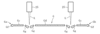
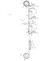
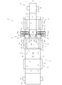
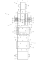
- FIG. 5 is a cross-sectional view taken along line VV of FIG. 2; It is sectional drawing of the glass film for demonstrating a cutting process. It is sectional drawing of the glass film for demonstrating a cutting process. It is sectional drawing of the glass film for demonstrating a cutting process. It is sectional drawing of the glass film for demonstrating a cutting process. It is a side view which shows the manufacturing apparatus of the glass film which concerns on 2nd embodiment. It is a top view of the manufacturing apparatus of a glass film.
- FIG. 9 is a cross-sectional view taken along line XX in FIG. It is a side view which shows the manufacturing apparatus of the glass film which concerns on 3rd embodiment. It is a top view of the manufacturing apparatus of a glass film. It is a side view which shows the manufacturing apparatus of the glass film which concerns on 4th embodiment. It is a top view of a control device of glass film.
- FIG. 1 to 6 show a first embodiment of a manufacturing apparatus for carrying out the method for manufacturing a glass film according to the present invention.
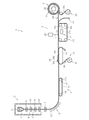
- FIG. 1 is a schematic side view schematically showing the entire configuration of a glass film manufacturing apparatus.
- the manufacturing apparatus 1 includes a forming unit 2 for forming a glass film G, a direction changing unit 3 for converting the traveling direction of the glass film G from the lower side to the horizontal direction, and the glass film after changing the direction.
- the horizontal conveyance unit 4 which conveys G in the lateral direction, and the cutting unit 5 which cuts the end portions Ga and Gb in the width direction of the glass film G as the non-product portion Gc while conveying in the lateral direction by the horizontal conveyance unit 4
- the product section Gd formed by cutting and removing the non-product section Gc by the section 5 is wound in a roll shape, and a winding section 6 constituting a glass roll R is provided.
- upstream (side) means a position near the forming unit 2 or the glass roll base material Ra
- downstream (side) means a position near the winding unit 6.
- the thickness of the product portion Gd in the present embodiment is 300 ⁇ m or less, preferably 10 ⁇ m to 200 ⁇ m, and more preferably 50 ⁇ m to 100 ⁇ m, but is not limited thereto.
- the forming portion 2 is a wedge-shaped formed body 7 having an overflow groove 7a formed at its upper end, and an edge roller which is disposed directly below the formed body 7 and sandwiches the molten glass overflowed from the formed body 7 from both front and back sides. 8 and an aniler 9 disposed immediately below the edge roller 8.
- the forming unit 2 causes the molten glass overflowed from above the overflow groove 7a of the forming body 7 to flow down along both side surfaces and merge at the lower end to form a film-like molten glass.
- the edge roller 8 regulates the contraction in the width direction of the molten glass to form a glass film G having a predetermined width.
- the aniler 9 is for performing a strain removal process on the glass film G.
- the anila 9 has an anila rollers 10 arranged in a plurality of stages in the vertical direction.
- the support roller 11 which clamps the glass film G from the front and back sides is disposed under the anila 9. A tension is applied between the support roller 11 and the edge roller 8 or between the support roller 11 and any one of the anila rollers 10 to promote thinning of the glass film G.
- the direction changing unit 3 is provided below the support roller 11.
- a plurality of guide rollers 12 for guiding the glass film G are arranged in a curved shape. These guide rollers 12 guide the glass film G conveyed in the vertical direction in the lateral direction.
- the lateral conveyance unit 4 is disposed forward (downstream) in the traveling direction of the direction conversion unit 3.
- the lateral conveyance unit 4 includes a first conveyance device 13, a second conveyance device 14, and a third conveyance device 15 in order from the upstream side.
- the first conveyance device 13 includes an endless belt-like conveyance belt 16 and a drive device 17 for the conveyance belt 16. By bringing the upper surface of the transport belt 16 into contact with the glass film G, the first transport device 13 continuously transports the glass film G having passed through the direction conversion unit 3 to the downstream side.
- the drive device 17 has a drive body 17 a such as a roller for driving the transport belt 16 and a sprocket, and a motor (not shown) for rotating the drive body 17 a.
- the second conveying device 14 has a platen 18 supporting the glass film G, and a sheet material 19 for conveying the glass film G.
- the platen 18 has a weir removing portion 20 for removing ⁇ Ge generated on the glass film G during conveyance.
- the wrinkle removing unit 20 includes a rod-like member 20 a.
- the rod-shaped member 20a is comprised by the member which has a cylindrical surface, it is not limited to this shape.
- the rod-like member 20a may have a curved surface which is convex upward to remove the ⁇ Ge of the glass film G, and may be formed in a semicircular or elliptical cross-sectional view.
- the rod-shaped member 20a is being fixed to the upper surface 18a of the surface plate 18, it is not limited to this form.
- the rod-like member 20 a may be configured to be rotatable at a position spaced upward from the upper surface 18 a of the platen 18. In this case, the rod-like member 20a may idle and may be rotationally driven by the drive means.
- the diameter D of the rod-like member 20a is set to 2 mm or more and 100 mm or less, but is not limited to this range, and may be appropriately set according to the dimensions of the glass film G and the product portion Gd.
- the height of the rod-like member 15a is preferably 10 mm or more and 100 mm or less, and contacts the glass through the conveying sheet 23 It is preferable that the curvature radius of the part is R1 mm or more and R100 mm or less.
- the rod-like members 20 a are disposed along the width direction W of the glass film G. That is, the rod-like member 20 a is disposed on the upper surface 18 a of the platen 18 so as to be orthogonal to the longitudinal direction of the glass film G.
- the length LR of the rod-like member 20 a is set shorter than the width WG of the glass film G.
- ear portion In the width direction end portions Ga and Gb of the glass film G, a portion (hereinafter referred to as “ear portion”) Gf having a thickness larger than that of the central portion is formed.
- the length LR of the rod-like member 20 a is set so as not to overlap the ear Gf when the rod-like member 20 a is disposed on the lower surface side of the glass film G. That is, in the glass film G, it is desirable that the length LR of the rod-like member 20a be set shorter than the width WC of the portion on the center side in the width direction not including the ear portion Gf.
- the rod-shaped member 20a which supports the glass film G supports the part by the side of the width direction center rather than the ear part Gf of the glass film G, without supporting the ear part Gf of the glass film G.
- the length LR of the rod-like member 20 a is preferably 1.1 times or more of the separation distance DL of the laser irradiation device 25 and 0.98 times or less of the width WC of the central portion of the glass film G.
- the sheet material 19 for conveyance is constituted by a foamed resin sheet, for example, it is not limited to this material.
- the sheet material 19 for conveyance is pulled out from the sheet roll 21 disposed below the surface plate 18, and moves on the surface plate 18 from the upstream side to the downstream side (see FIG. 1).
- the sheet material 19 for conveyance contacts the lower surface of the glass film G on the surface plate 18, and the said glass film G is conveyed downstream by the movement.
- the transport sheet 19 After passing through the upper surface 18 a of the platen 18, the transport sheet 19 is collected by a winding device (not shown) at a position below the platen 18.
- the width WS of the sheet material 19 for conveyance is set larger than the length LR of the rod-like member 20a. Further, the width WS of the transport sheet material 19 is set smaller than the width WG of the glass film G. More specifically, the width WS of the sheet material 19 for conveyance is preferably set to be smaller than the width WC of the widthwise center side portion of the glass film G which does not include the ear portion Gf (see FIG. 4).
- thickness TS of sheet material 19 for conveyance is set as 0.05 mm or more and 2 mm or less, it is not limited to this range, it sets suitably so that ear Gf of glass film G may not contact upper surface 18a of surface plate 18 It can be done.
- the third conveyance device 15 includes a platen 22 supporting the glass film G, and a sheet material 23 for conveying the glass film G.
- the third conveyance device 15 is cut by the cutting unit 5 by moving the conveyance sheet material 23 drawn from the sheet roll 24 disposed on the lower side on the upstream side of the surface plate 22 on the surface plate 22 to the downstream side.
- the non-product portion Gc and the product portion Gd of the glass film G are transported to the downstream side.
- the cutting unit 5 is disposed between the second conveyance device 14 and the third conveyance device 15 in the lateral conveyance unit 4.
- the cutting unit 5 includes a laser irradiation device 25, a platen 26 for supporting a glass film, and a collection device 27 for collecting a filamentous separated material Gg generated by irradiating the glass film G with the laser light L of the laser irradiation device 25. Equipped with
- the laser irradiation device 25 is disposed above the surface plate 26 and downstream of the crucible removing unit 20.
- the laser irradiation device 25 is configured to irradiate, for example, a CO 2 laser, a YAG laser or other laser light L downward.
- two laser irradiation devices 25 are disposed so as to cut the width direction both ends Ga and Gb of the glass film G (see FIG. 2).
- the laser beam L is irradiated to a predetermined position (irradiation position) O with respect to the glass film G.
- irradiation position a predetermined position
- the separation distance D1 between the irradiation position O and the rod-like member 20a of the wrinkles removing unit 20 is 200 mm or more and 2000 mm or less, it is not limited to this range, and it depends on the dimension of the glass film G and the dimension of the rod-like member 20a. Are set appropriately.
- the platen 26 has an opening 26 a penetrating in the vertical direction.
- the irradiation position O of the laser light L in the laser irradiation device 25 is set within the range of the opening 26 a.
- the recovery device 27 is disposed below the platen 26.
- the collection device 27 is constituted by a belt conveyor 27a.
- two belt conveyors 27 a are disposed corresponding to the respective ends Ga and Gb of the glass film G.
- Each belt conveyor 27a conveys the filamentous separated material Gg along the direction (width direction) orthogonal to the conveyance direction (longitudinal direction) of the glass film G, that is, from the inside to the outside in the width direction of the glass film G. .
- the winding unit 6 is disposed downstream of the third conveyance device 15.
- the winding unit 6 includes a winding roller 28, a motor (not shown) that rotationally drives the winding roller 28, and a protective sheet supply unit 29 that supplies a protective sheet 29a to the winding roller 28.
- the winding unit 6 winds the product portion Gd in a roll shape by rotating the winding roller 28 with a motor while overlapping the protective sheet 29a sent from the protective sheet supply unit 29 on the product portion Gd.
- the wound product part Gd is configured as a glass roll R.
- the manufacturing method of the glass roll R includes a forming step of forming a strip-shaped glass film G by the forming portion 2, a conveying step of conveying the glass film G by the direction changing portion 3 and the lateral conveying portion 4, and a glass film by the cutting portion 5 It comprises a cutting step of cutting the width direction end portions Ga and Gb of G, and a winding step of winding the product portion Gd by the winding portion 6 after the cutting step.
- the molten glass overflowing from the upper side of the overflow groove 7a of the formed body 7 in the forming portion 2 is allowed to flow down along both side surfaces and merged at the lower end to form a film-like molten glass.
- contraction in the width direction of the molten glass is regulated by the edge roller 8 to form a glass film G having a predetermined width.
- the glass film G is subjected to a strain removing process by the anila 9 (slow cooling process).
- the glass film G is formed to a predetermined thickness by the tension of the support roller 11.
- the transport direction of the glass film G is changed in the lateral direction by the direction conversion unit 3, and the glass film G is transported to the downstream winding unit 6 by the transport devices 13 to 15.
- the sheet material 19 for conveyance is lifted by the said rod-shaped member 20a, when passing the rod-shaped member 20a.
- a part on the upstream side of the rod-like member 20 a and a part on the downstream side of the rod-like member 20 a are separated from the upper surface 18 a of the surface plate 18.
- the separation distance in the vertical direction between the transport sheet material 19 and the upper surface 18 a of the platen 18 decreases as the transport sheet material 19 moves downstream from the rod-like member 20 a.
- the sheet material 19 for conveyance contacts the upper surface 18 a of the platen 18 on the upstream side of the irradiation position O of the laser light L in the laser irradiation device 25.
- the glass film G is supported by the surface plate 18 via the sheet material 19 for conveyance when the sheet material 19 for conveyance contacts the upper surface 18 a of the surface plate 18.
- the sheet material 19 for conveyance moves the glass film G to the irradiation position O of the laser beam L while maintaining the contact with the upper surface 18 a of the surface plate 18.
- the glass film G conveyed by the second conveying device 14 is irradiated with the laser light L from the laser irradiation device 25 of the cutting unit 5 to cut the widthwise end portions Ga and Gb of the glass film G. Thereby, the glass film G is separated into the non-product part Gc and the product part Gd.
- the fusion cutting part of glass film G is cooled.
- the melted portion causes thermal strain by being cooled, and the stress caused by this acts as a tensile force on the portion that is not melted. Due to this action, the threadlike separated material Gg is separated from the end in the width direction of the non-product portion Gc and the end in the width direction of the product portion Gd.
- the separated filamentous exfoliate Gg moves downward by its own weight (see FIG. 6C).
- the filamentous exfoliate Gg deforms in a spiral shape after being separated from the non-product portion Gc or the product portion Gd.
- the filamentous exfoliated material Gg generated from the non-product portion Gc and the product portion Gd is recovered by the recovery device 27 (recovery step).
- the non-product portion Gc is transported downstream by the third transport device 15, and is recovered upstream of the winding unit 6 by another recovery device (not shown).
- the product portion Gd conveyed by the third conveyance device 15 is formed into a roll by the winding roller 28 of the winding unit 6 while the protection sheet 29a is supplied from the protection sheet supply unit 29 to the product unit Gd. Take up.
- the glass roll R is completed by winding the product portion Gd having a predetermined length by the winding roller 28.
- the glass film G is cut by melting.
- the glass film G is stably supported by the upper surface 18 a of the platen 18 via the transport sheet material 19.
- a uniform thread-like peelable material Gg can be generated from the product portion Gd, and a high quality glass film G (glass roll R) can be manufactured by making the cut surface of the product portion Gd uniform.
- FIG. 7 to 10 show a second embodiment of a glass film manufacturing apparatus and method.
- the configurations of the second transfer device 14, the third transfer device 15, and the cutting unit 5 of the lateral transfer unit 4 are different from those in the first embodiment.
- the wrinkle removing unit 20 of the second conveyance device 14 includes a plate-like member 20 b disposed on the downstream side of the rod-like member 20 a. .
- the plate-like member 20 b is disposed between the rod-like member 20 a and the laser irradiation apparatus 25 in the conveyance direction of the glass film G.
- the plate member 20 b is fixed to the upper surface 18 a of the surface plate 18.
- the width WP (the length of the plate member 20b in the width direction W of the glass film G) of the plate member 20b is set smaller than the length LR of the rod member 20a.
- the width WP of the plate-like member 20 b is preferably 1.02 or more times as large as the separation distance DL of the laser irradiation device 25 and 0.95 or less times as long as the length LR of the rod-like member 20 a.
- the length LP of the plate member 20b in the transport direction of the glass film G is preferably 10 mm or more and 500 mm or less, but is not limited to this range, and is appropriately set according to the dimensions of the glass film G and the product portion Gd. Be done.
- the thickness TP of the plate member 20b is set smaller than the diameter D of the rod member 20a. Therefore, the upper surface 20c of the plate-like member is located below the upper end 20d of the rod-like member 20a.
- the thickness TP of the plate-like member 20b is 1 mm or more and 95 mm or less, but is not limited to this range, and is appropriately set according to the diameter D of the rod-like member 20a.
- the height difference between the upper surface 20c of the plate-like member 20b and the upper end 20d of the rod-like member 20a is preferably 3 mm or more and 50 mm or less.
- the separation distance D2 between the irradiation position O of the laser light L by the laser irradiation device 25 and the plate member 20b is 50 mm or more and 1950 mm or less, but not limited to this range It is suitably set according to the dimensions of G and the product part Gd.
- the separation distance D3 of the plate-shaped member 20b and the rod-shaped member 20a in the conveyance direction of the glass film G it is desirable to be 50 mm or more and 1500 mm or less.
- the third conveying device 15 has a plurality of (three in this example) conveying belts 30a to 30c for conveying the glass film G, and drive devices 31 for the respective conveying belts 30a to 30c.
- the transport belts 30 a to 30 c are configured in an endless belt shape, and the width direction of the glass film G and the first transport belt 30 a in contact with the portion on the width direction one end Ga side of the glass film G It includes a second conveyance belt 30b in contact with the other end Gb side, and a third conveyance belt 30c in contact with the widthwise center of the glass film G.
- the drive device 31 has a drive body 31 a such as a roller for driving the transport belts 30 a to 30 c and a sprocket, and a motor (not shown) for rotating the drive body 31 a.
- the transport belts 30a to 30c are separated in the width direction of the glass film G. Thus, gaps are formed between the first transport belt 30a and the third transport belt 30c and between the second transport belt 30b and the third transport belt 30c.
- the laser irradiation device 25 of the cutting unit 5 is disposed above the third transfer device 15.
- the irradiation position O of the laser light L in the laser irradiation device 25 is set to correspond to the gap between the transport belts 30a to 30c.
- the cutting unit 5 in the present embodiment does not include the surface plate 26 in the first embodiment, but may have a surface plate that can be disposed in the gap between the transport belts 30a to 30c.
- the recovery device 27 is disposed on the inner side of each of the transport belts 30a and 30b so as to cross the first transport belt 30a and the second transport belt 30b.
- the forming step, the conveying step, the cutting step, and the winding step are performed as in the first embodiment.
- the aspect of the wrinkles removal process in a conveyance process differs from 1st embodiment.
- the glass film G passes through the rod-like member 20 a provided on the surface plate 18 of the second conveyance device 14. At this time, the glass film G is pushed up above the upper surface 18 a of the surface plate 18 together with the transfer sheet material 19 by the rod-like members 20 a located on the lower surface side. At this time, most of ⁇ Ge generated in the glass film G disappears when the glass film G is stretched by the rod-like member 20a.
- the sheet material 19 for conveyance separates upwards from the upper surface 18a of the platen 18 when passing through the rod-like member 20a and the plate-like member 20b, but after passing through the plate-like member 20b, the irradiation position O of the laser beam L It contacts the upper surface 18a on the more upstream side. Thereby, the glass film G is supported by the upper surface 18 a of the platen 18 on the upstream side of the irradiation position O of the laser light L. Therefore, the glass film G is cut by the laser irradiation device 25 in a state of being stably supported by the upper surface 18 a of the platen 18. As a result, it is possible to continuously generate a uniform filiform release material Gg from the end in the width direction of the product portion Gd, and thereby it is possible to cut the glass film G with high accuracy.
- the laser light L is emitted from the laser irradiation device 25 disposed above.
- the non-product portion Gc of the glass film G is conveyed by the first conveyance belt 30a and the second conveyance belt 30b of the third conveyance device 15, The product portion Gd is transported by the third transport belt 30c.
- the forming process, the winding process, and other processes according to the present embodiment are the same as in the first embodiment.
- 11 and 12 show a third embodiment of a glass film manufacturing apparatus and method.
- the glass film G is manufactured using the overflow downdraw method, but in the present embodiment, the glass film G using the roll to roll process (Roll to Roll)
- the method of manufacturing (glass roll R) is illustrated.
- FIG.11 and FIG.12 it changes to the shaping
- the material Ra is provided on the most upstream side.
- the glass roll base material Ra is wound around the supply roller 32.
- the horizontal conveyance unit 4, the cutting unit 5, and the winding unit 6 are arranged in order.
- the configuration of each of these elements 4 to 6 is the same as that of the first embodiment.
- the manufacturing method of the glass film G (glass roll R) in this embodiment is a glass film supply process of drawing out the glass film G for processing from the glass roll base material Ra and supplying it to the downstream side, a conveying process, a cutting process, , And a winding process.
- the manufacturing apparatus 1 rotates the supply roller 32 to pull out the glass film G for processing from the glass roll base material Ra and move it to the downstream side.
- the subsequent transport process, cutting process and winding process are the same as in the first embodiment.
- the glass film G for processing in the cutting step, can be separated into a plurality of glass films G, and part or all of them can be used as a product.
- a plurality of winding rollers 28 are disposed in the winding unit 6 in accordance with the number of products to be manufactured.
- FIG. 13 and 14 show a fourth embodiment of a glass film manufacturing apparatus and a method of manufacturing a glass film using the manufacturing apparatus.
- FIG.13 and FIG.14 it changes to the shaping
- the material Ra is provided on the most upstream side.
- the glass roll base material Ra is wound around the supply roller 32.
- the horizontal conveyance unit 4, the cutting unit 5, and the winding unit 6 are arranged in order.
- the configuration of each of these elements 4 to 6 is the same as that of the second embodiment.
- the crucible removing portion 20 including one rod-like member 20a and one plate-like member 20b has been exemplified, but the invention is not limited thereto. Plate members may be disposed.
Landscapes
- Chemical & Material Sciences (AREA)
- Engineering & Computer Science (AREA)
- Materials Engineering (AREA)
- Organic Chemistry (AREA)
- Physics & Mathematics (AREA)
- Optics & Photonics (AREA)
- Plasma & Fusion (AREA)
- Mechanical Engineering (AREA)
- Health & Medical Sciences (AREA)
- Toxicology (AREA)
- Re-Forming, After-Treatment, Cutting And Transporting Of Glass Products (AREA)
- Laser Beam Processing (AREA)
Abstract
ガラスフィルムGの製造方法における搬送工程は、レーザ照射装置25よりも上流側に配置される皺除去部20によりガラスフィルムGの皺を取り除く皺除去工程を備える。ガラスフィルムGの製造方法における切断工程は、搬送工程においてガラスフィルムGの皺Geを除去した後に、レーザ光LをガラスフィルムGに照射することによりガラスフィルムGを分離し、分離されたガラスフィルムGの幅方向端部から糸状剥離物Ggを発生させる。
Description
本発明は、ロール状に巻き取ることが可能なガラスフィルムを製造する方法に関する。
周知のように、液晶ディスプレイ、有機ELディスプレイ等のフラットパネルディスプレイ(FPD)に用いられる板ガラス、有機EL照明に用いられる板ガラス、タッチパネルの構成要素である強化ガラス等の製造に用いられる板ガラス、更には太陽電池のパネル等に用いられる板ガラスは、薄肉化が推進されているのが実情である。
例えば特許文献1には、厚みが数百μm以下のガラスフィルム(薄板ガラス)が開示されている。この種のガラスフィルムは、同文献にも記載されるように、いわゆるオーバーフローダウンドロー法を採用した成形装置によって連続成形されるのが一般的である。
オーバーフローダウンドロー法により連続成形された長尺のガラスフィルムは、例えばその搬送方向が鉛直方向から水平方向に変換された後、搬送装置の横搬送部(水平搬送部)によって継続して下流側に搬送される。この搬送途中において、ガラスフィルムは、その幅方向両端部が切断除去される。その後、ガラスフィルムは、巻取りローラによってロール状に巻き取られることで、ガラスロールとして構成される。
ガラスフィルムの幅方向両端部を切断する技術として、特許文献1ではレーザ割断が開示されている。レーザ割断では、ダイヤモンドカッタ等のクラック形成手段によりガラスフィルムに初期クラックを形成した後、この部分にレーザ光を照射して加熱する。その後、加熱された部分を冷却手段により冷却し、ガラスフィルムに生じる熱応力により初期クラックを進展させてガラスフィルムを切断する。
他の切断方法として、特許文献2には、いわゆるピーリング現象を利用したガラスフィルムの切断技術が開示されている。この技術は、ガラスフィルム(ガラス基板)を搬送しつつ、当該ガラスフィルムにレーザ光を照射してその一部を溶断し、その溶断部分をレーザ光の照射領域から遠ざけることにより冷却する。
この場合において、溶断部分が冷却されることにより略糸状の剥離物(析出物)が生じる(例えば特許文献2の段落0044及び図3参照)。この糸状剥離物がガラスフィルムの端部から剥がれ落ちる現象を一般にピーリングと呼ぶ。糸状剥離物が生じることで、ガラスフィルムには、均一な切断面が形成されることになる。
ガラスフィルムは可撓性を有しているため、横搬送部で横方向に搬送される途中で、当該ガラスフィルムに皺が発生し得る。皺が発生すると、この皺及びその近傍に曲げ応力が発生する。したがって、ガラスフィルムに皺が生じたままの状態でレーザ光を照射すると、溶断部分に対して、皺に起因する不測の曲げ応力が付与されることになる。このため、ガラスフィルムの切断を精度良く行うことが困難になるという問題を招き得る。
本発明は上記の事情に鑑みて為されたものであり、ピーリングを利用してガラスフィルムを切断する場合に、ガラスフィルムに生じ得る皺を好適に除去し、ガラスフィルムを精度良く切断することを技術的課題とする。
本発明は上記の課題を解決するためのものであり、長尺状のガラスフィルムをその長手方向に沿って上流から下流に搬送する搬送工程と、前記搬送工程により前記ガラスフィルムを搬送しつつ、前記ガラスフィルムにレーザ照射装置からレーザ光を照射することにより、前記ガラスフィルムを分離する切断工程と、を備え、前記搬送工程は、前記レーザ照射装置よりも上流側に配置される皺除去部により前記ガラスフィルムの皺を取り除く皺除去工程を備え、前記切断工程は、前記搬送工程において前記ガラスフィルムの前記皺を除去した後に、前記レーザ光を前記ガラスフィルムに照射することにより前記ガラスフィルムを分離し、分離された前記ガラスフィルムの幅方向端部から糸状剥離物を発生させることを特徴とする。
かかる構成によれば、搬送工程において皺除去部によりガラスフィルムの皺を除去した後に、切断工程においてピーリングによるガラスフィルムの切断(溶断)を行うことで、ガラスフィルムの幅方向端部から均一な糸状剥離物を発生させることができる。これにより、ガラスフィルムの幅方向端部を均一な断面に形成することができ、よってガラスフィルムを精度良く切断することが可能になる。
上記のガラスフィルムの製造方法において、前記皺除去部は、前記ガラスフィルムの下面側であって前記ガラスフィルムの幅方向に沿って配置される棒状部材を備えることが望ましい。このように、搬送工程の皺除去工程では、ガラスフィルムがこの棒状部材を通過することにより、ガラスフィルムの皺を好適に消失させることができる。
また、前記皺除去部は、前記棒状部材と前記レーザ照射装置との間であって、前記ガラスフィルムの下面側に配置される板状部材を備え得る。皺除去工程では、ガラスフィルムが棒状部材及び板状部材を通過することで、ガラスフィルムの皺をより一層好適に消失させることが可能になる。
この場合において、前記板状部材の上面は、前記棒状部材の上端部よりも下方に位置することが望ましい。これにより、ガラスフィルムの皺を、棒状部材と板状部材とによって段階的に消失させることができる。
また、前記板状部材の幅は、前記棒状部材の長さよりも小さく設定されることが望ましい。
上記のガラスフィルムの製造方法において、前記レーザ照射装置は、前記ガラスフィルムの上方に配置されるとともに、前記ガラスフィルムの幅方向に対して所定の離間距離をおいて二台配置されており、前記板状部材の幅は、前記レーザ照射装置の前記離間距離よりも大きく設定されることが望ましい。なお、板状部材の幅とは、搬送されるガラスフィルムの長手方向に直交する幅方向における板状部材の寸法をいう。
上記のように板状部材の幅を二台のレーザ照射装置の離間距離よりも大きく設定することにより、レーザ光を照射する位置にガラスフィルムが到達する前に、確実にその皺を消失させることができる。
この場合において、前記板状部材の幅は、前記レーザ照射装置の前記離間距離の1.02倍以上前記棒状部材の長さの0.95倍以下であることが望ましい。
前記搬送工程では、前記ガラスフィルムの下面に接触する搬送用シート材を定盤上で移動させることにより前記ガラスフィルムを搬送し、前記皺除去部は、前記レーザ照射装置による前記レーザ光の照射位置よりも上流側であって、前記搬送用シート材を前記定盤の上面から上方に離間すべく前記上面に設置されており、前記レーザ光の前記照射位置の上流側において、前記搬送用シート材が前記定盤の前記上面に接触した状態であることが望ましい。
かかる構成によれば、皺除去部によって皺が取り除かれたガラスフィルムは、レーザ光の照射位置において、定盤の上面によって安定的に支持されることになる。これにより、レーザ光の照射位置においてガラスフィルムを精度良く切断できる。
本発明によれば、ピーリングを利用してガラスフィルムを切断する場合に、ガラスフィルムに生じ得る皺を好適に除去し、ガラスフィルムを精度良く切断することが可能になる。
以下、本発明を実施するための形態について図面を参照しながら説明する。図1乃至図6は、本発明に係るガラスフィルムの製造方法を実施するための製造装置の第一実施形態を示す。
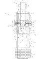
図1は、ガラスフィルムの製造装置の全体構成を模式的に示す概略側面図である。図1に示すように、製造装置1は、ガラスフィルムGを成形する成形部2と、ガラスフィルムGの進行方向を縦方向下方から横方向に変換する方向変換部3と、方向変換後にガラスフィルムGを横方向に搬送する横搬送部4と、横搬送部4で横方向に搬送しつつガラスフィルムGの幅方向端部Ga,Gbを非製品部Gcとして切断する切断部5と、この切断部5により非製品部Gcを切断除去してなる製品部Gdをロール状に巻き取ってガラスロールRを構成する巻取り部6とを備える。
なお、以下の説明において「上流」(側)とは、成形部2又はガラスロール元材Ra寄りの位置をいい、「下流」(側)とは、巻取り部6寄りの位置をいう。また、本実施形態における製品部Gdの厚みは、300μm以下とされ、好ましくは10μm以上200μm以下とされ、より好ましくは50μm以上100μm以下とされるが、これに限定されない。
成形部2は、上端部にオーバーフロー溝7aが形成された断面視略楔形の成形体7と、成形体7の直下に配置されて、成形体7から溢出した溶融ガラスを表裏両側から挟むエッジローラ8と、エッジローラ8の直下に配備されるアニーラ9とを備える。
成形部2は、成形体7のオーバーフロー溝7aの上方から溢流した溶融ガラスを、両側面に沿ってそれぞれ流下させ、下端で合流させてフィルム状の溶融ガラスを成形する。エッジローラ8は、溶融ガラスの幅方向収縮を規制して所定幅のガラスフィルムGとする。アニーラ9は、ガラスフィルムGに対して除歪処理を施すためのものである。このアニーラ9は、上下方向複数段に配設されたアニーラローラ10を有する。
アニーラ9の下方には、ガラスフィルムGを表裏両側から挟持する支持ローラ11が配設されている。支持ローラ11とエッジローラ8との間、または支持ローラ11と何れか一箇所のアニーラローラ10との間では、ガラスフィルムGを薄肉にすることを助長するための張力が付与されている。
方向変換部3は、支持ローラ11の下方位置に設けられている。方向変換部3には、ガラスフィルムGを案内する複数のガイドローラ12が湾曲状に配列されている。これらのガイドローラ12は、鉛直方向に搬送されるガラスフィルムGを横方向へと案内する。
横搬送部4は、方向変換部3の進行方向前方(下流側)に配置される。この横搬送部4は、上流側から順に、第一搬送装置13、第二搬送装置14、及び第三搬送装置15を有する。
第一搬送装置13は、無端帯状の搬送ベルト16と、この搬送ベルト16の駆動装置17とを有する。第一搬送装置13は、搬送ベルト16の上面をガラスフィルムGに接触させることで、方向変換部3を通過したガラスフィルムGを下流側へと連続的に搬送する。駆動装置17は、搬送ベルト16を駆動するためのローラ、スプロケット等の駆動体17aと、この駆動体17aを回転させるモータ(図示せず)を有する。
第二搬送装置14は、ガラスフィルムGを支持する定盤18と、ガラスフィルムGを搬送するためのシート材19とを有する。
定盤18は、搬送中にガラスフィルムGに生じる皺Geを取り除くための皺除去部20を有する。本実施形態において、皺除去部20は、棒状部材20aを含む。棒状部材20aは、円筒面を有する部材により構成されるが、この形状に限定されない。棒状部材20aは、ガラスフィルムGの皺Geを除去すべく、上方に凸となる曲面を有していればよく、断面視半円形や楕円形に構成されてもよい。
図3に示すように、棒状部材20aは、定盤18の上面18aに固定されているが、この形態に限定されない。棒状部材20aは、定盤18の上面18aから上方に離間した位置にて回転可能に構成されてもよい。この場合、棒状部材20aは、空転してもよく、駆動手段によって回転駆動されてもよい。棒状部材20aの直径Dは、2mm以上100mm以下に設定されるが、この範囲に限定されず、ガラスフィルムGや製品部Gdの寸法等に応じて適宜設定され得る。また、棒状部材15aが円筒形以外の場合(例えば三角柱状や半円柱状)、棒状部材15aの高さは10mm以上100mm以下であることが好ましく、搬送用シート材23を介してガラスと接触する部分の曲率半径がR1mm以上、R100mm以下であることが好ましい。
棒状部材20aは、ガラスフィルムGの幅方向Wに沿って配置される。すなわち、棒状部材20aは、ガラスフィルムGの長手方向に対して直交するように、定盤18の上面18aに配置される。
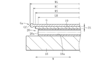
図2及び図4に示すように、棒状部材20aの長さLRは、ガラスフィルムGの幅WGよりも短く設定される。
ガラスフィルムGの幅方向端部Ga,Gbには、中央部よりも厚さが大きな部分(以下「耳部」という)Gfが形成される。棒状部材20aの長さLRは、ガラスフィルムGの下面側に棒状部材20aを配置した場合に、この耳部Gfに重ならないように設定される。すなわち、棒状部材20aの長さLRは、ガラスフィルムGにおいて、耳部Gfを含まない幅方向中央側の部分の幅WCよりも短く設定されることが望ましい。これにより、ガラスフィルムGを支持する棒状部材20aは、ガラスフィルムGの耳部Gfを支持することなく、ガラスフィルムGの耳部Gfよりも幅方向中央側の部分を支持する。棒状部材20aの長さLRは、レーザ照射装置25の離間距離DLの1.1倍以上、ガラスフィルムGの中央側の部分の幅WCの0.98倍以下であることが好ましい。
搬送用シート材19は、例えば発泡樹脂シートにより構成されるが、この材料に限定されるものではない。搬送用シート材19は、定盤18の下方に配置されるシートロール21から引き出され、定盤18上を上流側から下流側へと移動する(図1参照)。搬送用シート材19は、定盤18上において、ガラスフィルムGの下面に接触し、その移動により当該ガラスフィルムGを下流側へと搬送する。搬送用シート材19は、定盤18の上面18aを通過した後に、定盤18の下方位置において、図示しない巻取り装置によって回収される。
搬送用シート材19の幅WSは、棒状部材20aの長さLRよりも大きく設定される。また、搬送用シート材19の幅WSは、ガラスフィルムGの幅WGよりも小さく設定される。より詳細には、搬送用シート材19の幅WSは、ガラスフィルムGにおいて、耳部Gfを含まない幅方向中央側の部分の幅WCよりも小さく設定されることが望ましい(図4参照)。
搬送用シート材19の厚みTSは、0.05mm以上2mm以下に設定されるが、この範囲に限定されず、ガラスフィルムGの耳部Gfが定盤18の上面18aに接触させないように適宜設定され得る。
第三搬送装置15は、ガラスフィルムGを支持する定盤22と、ガラスフィルムGを搬送するためのシート材23とを有する。第三搬送装置15は、定盤22の上流側下方に配置されるシートロール24から引き出された搬送用シート材23を定盤22上で下流側に移動させることにより、切断部5によって切断されたガラスフィルムGの非製品部Gc及び製品部Gdを下流側へと搬送する。
図1及び図2に示すように、切断部5は、横搬送部4における第二搬送装置14と第三搬送装置15との間に配置される。切断部5は、レーザ照射装置25と、ガラスフィルムを支持する定盤26と、レーザ照射装置25のレーザ光LをガラスフィルムGに照射することにより生じる糸状剥離物Ggを回収する回収装置27とを備える。
レーザ照射装置25は、定盤26の上方であって、皺除去部20よりも下流側に配置される。レーザ照射装置25は、例えばCO2レーザ、YAGレーザその他のレーザ光Lを下方に向けて照射するように構成される。本実施形態では、ガラスフィルムGの幅方向両端部Ga,Gbを切断するように、二台のレーザ照射装置25が配置されている(図2参照)。
レーザ光Lは、ガラスフィルムGに対して所定の位置(照射位置)Oに照射される。この照射位置Oと、皺除去部20の棒状部材20aとの離間距離D1は、200mm以上2000mm以下とされるが、この範囲に限定されず、ガラスフィルムGの寸法及び棒状部材20aの寸法に応じて適宜設定される。
定盤26は、上下方向に貫通する開口部26aを有する。レーザ照射装置25におけるレーザ光Lの照射位置Oは、この開口部26aの範囲内に設定される。
図2及び図3に示すように、回収装置27は、定盤26の下方に配置される。回収装置27は、ベルトコンベア27aにより構成される。本実施形態では、ガラスフィルムGの各端部Ga,Gbに対応して、二台のベルトコンベア27aが配置される。各ベルトコンベア27aは、ガラスフィルムGの搬送方向(長手方向)に直交する方向(幅方向)に沿って、すなわち、ガラスフィルムGの幅方向における内側から外側に向かって糸状剥離物Ggを搬送する。
巻取り部6は、第三搬送装置15の下流側に設置されている。巻取り部6は、巻取りローラ28と、この巻取りローラ28を回転駆動するモータ(図示せず)と、巻取りローラ28に保護シート29aを供給する保護シート供給部29とを有する。巻取り部6は、保護シート供給部29から送られる保護シート29aを製品部Gdに重ね合わせつつ、モータにより巻取りローラ28を回転させることで、製品部Gdをロール状に巻き取る。巻き取られた製品部Gdは、ガラスロールRとして構成される。
以下、上記構成の製造装置1によりガラスロールRを製造する方法について説明する。ガラスロールRの製造方法は、成形部2によって帯状のガラスフィルムGを成形する成形工程と、方向変換部3及び横搬送部4によりガラスフィルムGを搬送する搬送工程と、切断部5によりガラスフィルムGの幅方向端部Ga,Gbを切断する切断工程と、切断工程後に製品部Gdを巻取り部6によって巻き取る巻取り工程とを備える。
成形工程では、成形部2における成形体7のオーバーフロー溝7aの上方から溢流した溶融ガラスを、両側面に沿ってそれぞれ流下させ、下端で合流させてフィルム状の溶融ガラスとする。この際、溶融ガラスの幅方向収縮をエッジローラ8により規制して所定幅のガラスフィルムGとする。その後、ガラスフィルムGに対してアニーラ9により除歪処理を施す(徐冷工程)。支持ローラ11の張力により、ガラスフィルムGは所定の厚みに形成される。
搬送工程では、方向変換部3によってガラスフィルムGの搬送方向を横方向に変換するとともに、各搬送装置13~15によって、ガラスフィルムGを下流側の巻取り部6へと搬送する。
ガラスフィルムGには、横搬送部4による搬送中に多数の皺Geが不規則に生じる。これらの皺Geは、ガラスフィルムGが第二搬送装置14の皺除去部20を通過することにより消失する(皺除去工程)。すなわち、ガラスフィルムGは、皺除去部20の棒状部材20aを通過する際、その下面側に位置する棒状部材20aによって、搬送用シート材19とともに定盤18の上面18aよりも上方位置に押し上げられる。このとき、ガラスフィルムGの皺Geは、ガラスフィルムGが棒状部材20aによって引き伸ばされることにより消失する。
搬送用シート材19は、棒状部材20aを通過する際に、当該棒状部材20aによって持ち上げられる。これにより、搬送用シート材19は、棒状部材20aよりも上流側の一部と、棒状部材20aよりも下流側の一部とが定盤18の上面18aから離間する。図3に示すように、搬送用シート材19と定盤18の上面18aとの上下方向における離間距離は、搬送用シート材19が棒状部材20aから下流に移動するにつれて小さくなる。搬送用シート材19は、レーザ照射装置25におけるレーザ光Lの照射位置Oよりも上流側で、定盤18の上面18aに接触する。
ガラスフィルムGは、搬送用シート材19が定盤18の上面18aに接触することにより、当該搬送用シート材19を介して定盤18に支持される。搬送用シート材19は、定盤18の上面18aとの接触を維持しながら、ガラスフィルムGをレーザ光Lの照射位置Oへと移動させる。
切断工程では、第二搬送装置14により搬送されるガラスフィルムGに、切断部5のレーザ照射装置25からレーザ光Lを照射して、ガラスフィルムGの幅方向両端部Ga,Gbを切断する。これにより、ガラスフィルムGは非製品部Gcと製品部Gdとに分離する。
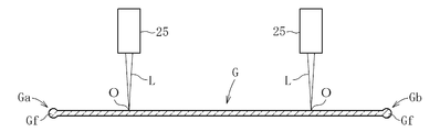
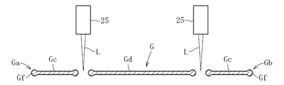
具体的には、レーザ光LがガラスフィルムGに照射されると(図6A参照)、ガラスフィルムGの一部がレーザ光Lの加熱により溶断される(図6B参照)。ガラスフィルムGは、第二搬送装置14によって搬送されているため、溶断された部分はレーザ光Lから遠ざかる。
これにより、ガラスフィルムGの溶断部分が冷却される。溶断部分は、冷却されることにより熱歪を生じ、これによる応力が、溶断されていない部分に対して引張力として作用する。この作用により、糸状剥離物Ggは、非製品部Gcの幅方向端部、及び製品部Gdの幅方向端部から分離する。分離した糸状剥離物Ggは、その自重により下方に移動する(図6C参照)。糸状剥離物Ggは、非製品部Gc又は製品部Gdから分離した後に、螺旋状に変形する。切断工程では、非製品部Gcと製品部Gdとから生じる糸状剥離物Ggを回収装置27により回収する(回収工程)。
なお、非製品部Gcは、第三搬送装置15により下流側に搬送され、巻取り部6の上流側で、図示しない別の回収装置により回収される。
巻取り工程では、保護シート供給部29から保護シート29aを製品部Gdに供給しつつ、第三搬送装置15によって搬送される製品部Gdを巻取り部6の巻取りローラ28にてロール状に巻き取る。所定長さの製品部Gdを巻取りローラ28により巻き取ることで、ガラスロールRが完成する。
以上説明した本実施形態に係るガラスフィルムGの製造方法によれば、切断工程において、皺除去部20(棒状部材20a)によりガラスフィルムGの皺Geを除去した上でガラスフィルムGの溶断を行うことで、ガラスフィルムGから製品部Gdを精度良く切り出すことが可能になる。レーザ照射装置25によるレーザ光Lの照射位置Oにおいて、ガラスフィルムGは、搬送用シート材19を介して定盤18の上面18aに安定的に支持される。これにより、製品部Gdから均一な糸状剥離物Ggを発生させることができ、製品部Gdの切断面を均一にすることで、高品質なガラスフィルムG(ガラスロールR)を製造できる。
図7乃至図10は、ガラスフィルムの製造装置及び製造方法の第二実施形態を示す。本実施形態では、横搬送部4の第二搬送装置14、第三搬送装置15、及び切断部5の構成が第一実施形態とは異なる。
図7乃至図9に示すように、第二搬送装置14の皺除去部20は、第一実施形態における棒状部材20aに加え、当該棒状部材20aの下流側に配置される板状部材20bを備える。
板状部材20bは、ガラスフィルムGの搬送方向において、棒状部材20aとレーザ照射装置25との間に配置される。板状部材20bは、定盤18の上面18aに固定されている。板状部材20bの幅WP(ガラスフィルムGの幅方向Wにおける板状部材20bの長さ)は、棒状部材20aの長さLRよりも小さく設定される。板状部材20bの幅WPは、レーザ照射装置25の離間距離DLの1.02倍以上、棒状部材20aの長さLRの0.95倍以下であることが好ましい。ガラスフィルムGの搬送方向における板状部材20bの長さLPは、10mm以上500mm以下とされることが望ましいが、この範囲に限定されず、ガラスフィルムG及び製品部Gdの寸法に応じて適宜設定される。
板状部材20bの厚みTPは棒状部材20aの直径Dよりも小さく設定される。したがって、板状部材の上面20cは、棒状部材20aの上端部20dよりも下方に位置する。この板状部材20bの厚みTPは、1mm以上、95mm以下とされるが、この範囲に限定されず、棒状部材20aの直径Dに応じて適宜設定される。板状部材20bの上面20cと、棒状部材20aの上端部20dとの高低差は、3mm以上50mm以下とされることが望ましい。
ガラスフィルムGの搬送方向において、レーザ照射装置25によるレーザ光Lの照射位置Oと板状部材20bとの離間距離D2は、50mm以上1950mm以下とされるが、この範囲に限定されず、ガラスフィルムG及び製品部Gdの寸法に応じて適宜設定される。また、ガラスフィルムGの搬送方向における板状部材20bと棒状部材20aとの離間距離D3は、50mm以上1500mm以下とされることが望ましい。
第三搬送装置15は、ガラスフィルムGを搬送する複数(本例では三本)の搬送ベルト30a~30cと、各搬送ベルト30a~30cの駆動装置31とを有する。図8に示すように、搬送ベルト30a~30cは、無端帯状に構成されるとともに、ガラスフィルムGの幅方向一端部Ga側の部分に接触する第一搬送ベルト30aと、ガラスフィルムGの幅方向他端部Gb側の部分に接触する第二搬送ベルト30bと、ガラスフィルムGの幅方向中央部に接触する第三搬送ベルト30cとを含む。駆動装置31は、各搬送ベルト30a~30cを駆動するためのローラ、スプロケット等の駆動体31aと、この駆動体31aを回転させるモータ(図示せず)を有する。
図8に示すように、各搬送ベルト30a~30cは、ガラスフィルムGの幅方向において離間されている。これにより、第一搬送ベルト30aと第三搬送ベルト30cとの間、第二搬送ベルト30bと第三搬送ベルト30cとの間には、隙間が形成される。
切断部5のレーザ照射装置25は、第三搬送装置15の上方に配置される。レーザ照射装置25におけるレーザ光Lの照射位置Oは、各搬送ベルト30a~30cの間の隙間に対応するように設定される。本実施形態における切断部5は、第一実施形態における定盤26を備えていないが、各搬送ベルト30a~30cの隙間に配置可能な定盤を備えてもよい。回収装置27は、第一搬送ベルト30a及び第二搬送ベルト30bを横切るように、各搬送ベルト30a,30bの内側に配置される。
本実施形態に係る製造装置1によりガラスフィルムG(ガラスロールR)を製造する場合、第一実施形態と同様に、成形工程、搬送工程、切断工程、及び巻取り工程を実行することとなるが、搬送工程における皺除去工程の態様が第一実施形態とは異なる。
皺除去工程では、まず、ガラスフィルムGが第二搬送装置14の定盤18に設けられる棒状部材20aを通過する。この際、ガラスフィルムGは、その下面側に位置する棒状部材20aによって、搬送用シート材19とともに定盤18の上面18aよりも上方位置に押し上げられる。このとき、ガラスフィルムGに生じている皺Geの多くは、ガラスフィルムGが棒状部材20aによって引き伸ばされることにより消失する。
棒状部材20aを通過した後においてもガラスフィルムGに皺Geが残存する場合、当該皺Geは、ガラスフィルムGが板状部材20bを通過することにより消失する。搬送用シート材19を介してガラスフィルムGに線状に接触する棒状部材20aに対し、板状部材20bは、搬送用シート材19を介して、いわば面状に接触する。これにより、棒状部材20aによって除去されなかった皺Geは、ガラスフィルムGが板状部材20bを通過することにより確実に消失する。
搬送用シート材19は、棒状部材20a及び板状部材20bを通過する際に、定盤18の上面18aから上方に離間するが、板状部材20bを通過した後に、レーザ光Lの照射位置Oよりも上流側で、当該上面18aに接触する。これにより、ガラスフィルムGは、レーザ光Lの照射位置Oよりも上流側で、定盤18の上面18aに支持される。したがって、ガラスフィルムGは、定盤18の上面18aに安定的に支持された状態で、レーザ照射装置25によって切断される。これにより、製品部Gdの幅方向端部から均一な糸状剥離物Ggを連続的に発生させることができ、もってガラスフィルムGの切断を精度良く実行できる。
本実施形態に係る切断工程では、第三搬送装置15によってガラスフィルムGを搬送しながら、上方に配置されるレーザ照射装置25からレーザ光Lを照射する。その後、糸状剥離物Ggを回収装置27により回収しつつ(図10参照)、ガラスフィルムGの非製品部Gcを第三搬送装置15の第一搬送ベルト30a及び第二搬送ベルト30bにより搬送し、製品部Gdを第三搬送ベルト30cにより搬送する。本実施形態に係る成形工程、巻取り工程その他の工程は、第一実施形態と同じである。
図11及び図12は、ガラスフィルムの製造装置及び製造方法の第三実施形態を示す。上記の第一、第二実施形態では、オーバーフローダウンドロー法を用いてガラスフィルムGを製造する例を示したが、本実施形態では、ロールトゥロール工程(Roll to Roll)を用いてガラスフィルムG(ガラスロールR)を製造する方法を例示する。
図11及び図12に示すように、製造装置1は、第一実施形態における成形部2、方向変換部3に替えて、加工対象であるガラスフィルムGをロール状に構成してなるガラスロール元材Raを最も上流側に備える。ガラスロール元材Raは、供給ローラ32に巻き取られて成る。ガラスロール元材Raの下流側には、第一実施形態と同様に、横搬送部4、切断部5、巻取り部6が順に配置される。これらの各要素4~6の構成は第一実施形態と同じである。
本実施形態におけるガラスフィルムG(ガラスロールR)の製造方法は、ガラスロール元材Raから加工用のガラスフィルムGを引き出して下流側に供給するガラスフィルム供給工程と、搬送工程と、切断工程と、巻取り工程とを備える。ガラスフィルム供給工程において、製造装置1は、供給ローラ32を回転させることにより、ガラスロール元材Raから加工用のガラスフィルムGを引き出して下流側へと移動させる。以降の搬送工程、切断工程及び巻取り工程は、第一実施形態と同様である。
本実施形態では、切断工程において、加工用のガラスフィルムGを複数のガラスフィルムGに分離させ、その一部又は全てを製品とすることができる。この場合、製造される製品の数に応じて、複数の巻取りローラ28が巻取り部6に配置される。
図13及び図14は、ガラスフィルムの製造装置及び当該製造装置を用いてガラスフィルムを製造する方法の第四実施形態を示す。
図13及び図14に示すように、製造装置1は、第二実施形態における成形部2、方向変換部3に替えて、加工対象であるガラスフィルムGをロール状に構成してなるガラスロール元材Raを最も上流側に備える。ガラスロール元材Raは、供給ローラ32に巻き取られて成る。ガラスロール元材Raの下流側には、第二実施形態と同様に、横搬送部4、切断部5、巻取り部6が順に配置される。これらの各要素4~6の構成は第二実施形態と同じである。
なお、本発明は、上記実施形態の構成に限定されるものではなく、上記した作用効果に限定されるものでもない。本発明は、本発明の要旨を逸脱しない範囲で種々の変更が可能である。
上記の第二実施形態では、一本の棒状部材20a、一枚の板状部材20bを含む皺除去部20を例示したが、これに限定されず、定盤18上に複数の棒状部材、複数の板状部材を配置してもよい。
18 定盤
18a 定盤の上面
19 搬送用シート材
20 皺除去部
20a 棒状部材
20b 板状部材
20c 板状部材の上面
20d 棒状部材の上端部
25 レーザ照射装置
DL レーザ照射装置の離間距離
G ガラスフィルム
Ge ガラスフィルムの皺
Gg 糸状剥離物
L レーザ光
O レーザ光の照射位置
W ガラスフィルムの幅方向
WP 板状部材の幅
LR 棒状部材の長さ
18a 定盤の上面
19 搬送用シート材
20 皺除去部
20a 棒状部材
20b 板状部材
20c 板状部材の上面
20d 棒状部材の上端部
25 レーザ照射装置
DL レーザ照射装置の離間距離
G ガラスフィルム
Ge ガラスフィルムの皺
Gg 糸状剥離物
L レーザ光
O レーザ光の照射位置
W ガラスフィルムの幅方向
WP 板状部材の幅
LR 棒状部材の長さ
Claims (8)
- 長尺状のガラスフィルムをその長手方向に沿って上流から下流に搬送する搬送工程と、
前記搬送工程により前記ガラスフィルムを搬送しつつ、前記ガラスフィルムにレーザ照射装置からレーザ光を照射することにより、前記ガラスフィルムを分離する切断工程と、を備え、
前記搬送工程は、前記レーザ照射装置よりも上流側に配置される皺除去部により前記ガラスフィルムの皺を取り除く皺除去工程を備え、
前記切断工程は、前記搬送工程において前記ガラスフィルムの前記皺を除去した後に、前記レーザ光を前記ガラスフィルムに照射することにより前記ガラスフィルムを分離し、分離された前記ガラスフィルムの幅方向端部から糸状剥離物を発生させることを特徴とするガラスフィルムの製造方法。 - 前記皺除去部は、前記ガラスフィルムの下面側であって前記ガラスフィルムの幅方向に沿って配置される棒状部材を備える請求項1に記載のガラスフィルムの製造方法。
- 前記皺除去部は、前記棒状部材と前記レーザ照射装置との間であって、前記ガラスフィルムの下面側に配置される板状部材を備える請求項2に記載のガラスフィルムの製造方法。
- 前記板状部材の上面は、前記棒状部材の上端部よりも下方に位置する請求項3に記載のガラスフィルムの製造方法。
- 前記板状部材の幅は、前記棒状部材の長さよりも小さく設定される請求項3又は4に記載のガラスフィルムの製造方法。
- 前記レーザ照射装置は、前記ガラスフィルムの上方に配置されるとともに、前記ガラスフィルムの幅方向に対して所定の離間距離をおいて二台配置されており、前記板状部材の幅は、前記レーザ照射装置の前記離間距離よりも大きく設定される請求項3から5のいずれか一項に記載のガラスフィルムの製造方法。
- 前記板状部材の幅は、前記レーザ照射装置の前記離間距離の1.02倍以上前記棒状部材の長さの0.95倍以下である請求項6に記載のガラスフィルムの製造方法。
- 前記搬送工程では、前記ガラスフィルムの下面に接触する搬送用シート材を定盤上で移動させることにより前記ガラスフィルムを搬送し、
前記皺除去部は、前記レーザ照射装置による前記レーザ光の照射位置よりも上流側であって、前記搬送用シート材を前記定盤の上面から上方に離間すべく前記上面に設置されており、
前記レーザ光の前記照射位置の上流側において、前記搬送用シート材が前記定盤の前記上面に接触した状態である請求項1から7のいずれか一項に記載のガラスフィルムの製造方法。
Priority Applications (3)
| Application Number | Priority Date | Filing Date | Title |
|---|---|---|---|
| CN202210370989.XA CN114573224B (zh) | 2017-07-31 | 2018-07-09 | 玻璃膜的制造方法 |
| CN201880028039.0A CN110573465B (zh) | 2017-07-31 | 2018-07-09 | 玻璃膜的制造方法 |
| KR1020197024631A KR102475077B1 (ko) | 2017-07-31 | 2018-07-09 | 유리 필름의 제조 방법 |
Applications Claiming Priority (2)
| Application Number | Priority Date | Filing Date | Title |
|---|---|---|---|
| JP2017-147827 | 2017-07-31 | ||
| JP2017147827A JP6909403B2 (ja) | 2017-07-31 | 2017-07-31 | ガラスフィルムの製造方法 |
Publications (1)
| Publication Number | Publication Date |
|---|---|
| WO2019026554A1 true WO2019026554A1 (ja) | 2019-02-07 |
Family
ID=65232749
Family Applications (1)
| Application Number | Title | Priority Date | Filing Date |
|---|---|---|---|
| PCT/JP2018/025883 Ceased WO2019026554A1 (ja) | 2017-07-31 | 2018-07-09 | ガラスフィルムの製造方法 |
Country Status (5)
| Country | Link |
|---|---|
| JP (1) | JP6909403B2 (ja) |
| KR (1) | KR102475077B1 (ja) |
| CN (2) | CN114573224B (ja) |
| TW (1) | TWI759509B (ja) |
| WO (1) | WO2019026554A1 (ja) |
Cited By (2)
| Publication number | Priority date | Publication date | Assignee | Title |
|---|---|---|---|---|
| CN113383495A (zh) * | 2019-03-14 | 2021-09-10 | 索尼半导体解决方案公司 | 固态摄像元件和摄像装置 |
| WO2025100098A1 (ja) * | 2023-11-07 | 2025-05-15 | 日本電気硝子株式会社 | ガラス物品の製造装置 |
Families Citing this family (4)
| Publication number | Priority date | Publication date | Assignee | Title |
|---|---|---|---|---|
| WO2021131617A1 (ja) * | 2019-12-23 | 2021-07-01 | 日本電気硝子株式会社 | ガラスフィルムの製造方法及びその製造装置 |
| JP7365002B2 (ja) * | 2019-12-24 | 2023-10-19 | 日本電気硝子株式会社 | ガラスフィルムの製造方法、及びガラスフィルムの製造装置 |
| WO2021131559A1 (ja) | 2019-12-24 | 2021-07-01 | 日本電気硝子株式会社 | ガラスフィルムの製造方法、ガラスロールの製造方法、及びガラスフィルムの製造装置 |
| JP7557712B2 (ja) * | 2020-12-09 | 2024-09-30 | 日本電気硝子株式会社 | ガラスフィルムの製造方法 |
Citations (3)
| Publication number | Priority date | Publication date | Assignee | Title |
|---|---|---|---|---|
| WO2014192482A1 (ja) * | 2013-05-28 | 2014-12-04 | 旭硝子株式会社 | ガラス基板の切断方法及びガラス基板の製造方法 |
| JP2015063450A (ja) * | 2013-08-28 | 2015-04-09 | 日本電気硝子株式会社 | ガラスフィルムリボン製造方法及びガラスフィルムリボン製造装置 |
| JP2015140280A (ja) * | 2014-01-29 | 2015-08-03 | 旭硝子株式会社 | ガラス板の製造方法及びガラス板 |
Family Cites Families (12)
| Publication number | Priority date | Publication date | Assignee | Title |
|---|---|---|---|---|
| JP4172112B2 (ja) * | 1999-09-03 | 2008-10-29 | 旭硝子株式会社 | ガラスリボンの割断方法 |
| JP5742082B2 (ja) * | 2011-06-30 | 2015-07-01 | 日本電気硝子株式会社 | ガラスロールの製造方法 |
| JP5720885B2 (ja) * | 2010-03-03 | 2015-05-20 | 日本電気硝子株式会社 | ガラスロール、及びガラスロールの製造方法 |
| JP2011207721A (ja) * | 2010-03-30 | 2011-10-20 | Nippon Electric Glass Co Ltd | ガラスフィルムの切断方法及びガラスロールの製造方法 |
| JP5874159B2 (ja) * | 2010-08-31 | 2016-03-02 | 日本電気硝子株式会社 | ガラス−樹脂積層体、およびそれを巻き取ったガラスロール、並びにガラスロールの製造方法 |
| JP5617556B2 (ja) * | 2010-11-22 | 2014-11-05 | 日本電気硝子株式会社 | 帯状ガラスフィルム割断装置及び帯状ガラスフィルム割断方法 |
| JP5679324B2 (ja) | 2011-05-19 | 2015-03-04 | 日本電気硝子株式会社 | ガラスロールの製造方法および製造装置 |
| JP5888158B2 (ja) * | 2012-04-05 | 2016-03-16 | 日本電気硝子株式会社 | ガラスフィルムの割断方法 |
| JP6206406B2 (ja) | 2012-06-28 | 2017-10-04 | 旭硝子株式会社 | ガラス基板の切断方法及びガラス基板の製造方法 |
| TW201412658A (zh) * | 2012-09-26 | 2014-04-01 | Corning Inc | 用於可撓式玻璃帶之邊緣修正管理 |
| JP6136070B2 (ja) * | 2013-08-28 | 2017-05-31 | 日本電気硝子株式会社 | ガラスフィルムリボン製造方法及びガラスフィルムリボン製造装置 |
| EP3040317B1 (en) * | 2013-08-28 | 2019-09-25 | Nippon Electric Glass Co., Ltd. | Glass film ribbon manufacturing method and glass film ribbon manufacturing device |
-
2017
- 2017-07-31 JP JP2017147827A patent/JP6909403B2/ja active Active
-
2018
- 2018-07-09 CN CN202210370989.XA patent/CN114573224B/zh active Active
- 2018-07-09 CN CN201880028039.0A patent/CN110573465B/zh active Active
- 2018-07-09 WO PCT/JP2018/025883 patent/WO2019026554A1/ja not_active Ceased
- 2018-07-09 KR KR1020197024631A patent/KR102475077B1/ko active Active
- 2018-07-20 TW TW107125046A patent/TWI759509B/zh active
Patent Citations (3)
| Publication number | Priority date | Publication date | Assignee | Title |
|---|---|---|---|---|
| WO2014192482A1 (ja) * | 2013-05-28 | 2014-12-04 | 旭硝子株式会社 | ガラス基板の切断方法及びガラス基板の製造方法 |
| JP2015063450A (ja) * | 2013-08-28 | 2015-04-09 | 日本電気硝子株式会社 | ガラスフィルムリボン製造方法及びガラスフィルムリボン製造装置 |
| JP2015140280A (ja) * | 2014-01-29 | 2015-08-03 | 旭硝子株式会社 | ガラス板の製造方法及びガラス板 |
Cited By (3)
| Publication number | Priority date | Publication date | Assignee | Title |
|---|---|---|---|---|
| CN113383495A (zh) * | 2019-03-14 | 2021-09-10 | 索尼半导体解决方案公司 | 固态摄像元件和摄像装置 |
| CN113383495B (zh) * | 2019-03-14 | 2025-05-16 | 索尼半导体解决方案公司 | 固态摄像元件和摄像装置 |
| WO2025100098A1 (ja) * | 2023-11-07 | 2025-05-15 | 日本電気硝子株式会社 | ガラス物品の製造装置 |
Also Published As
| Publication number | Publication date |
|---|---|
| TW201918460A (zh) | 2019-05-16 |
| TWI759509B (zh) | 2022-04-01 |
| KR20200035369A (ko) | 2020-04-03 |
| JP2019026509A (ja) | 2019-02-21 |
| CN114573224B (zh) | 2024-07-19 |
| CN110573465B (zh) | 2022-04-12 |
| KR102475077B1 (ko) | 2022-12-07 |
| CN114573224A (zh) | 2022-06-03 |
| JP6909403B2 (ja) | 2021-07-28 |
| CN110573465A (zh) | 2019-12-13 |
Similar Documents
| Publication | Publication Date | Title |
|---|---|---|
| WO2019026554A1 (ja) | ガラスフィルムの製造方法 | |
| CN110382425B (zh) | 玻璃膜的制造方法 | |
| CN108883964B (zh) | 玻璃膜的制造方法 | |
| CN111278779B (zh) | 玻璃卷筒的制造方法 | |
| CN108698904B (zh) | 玻璃卷的制造方法 | |
| TWI729265B (zh) | 玻璃膜之製造方法 |
Legal Events
| Date | Code | Title | Description |
|---|---|---|---|
| 121 | Ep: the epo has been informed by wipo that ep was designated in this application |
Ref document number: 18841292 Country of ref document: EP Kind code of ref document: A1 |
|
| ENP | Entry into the national phase |
Ref document number: 20197024631 Country of ref document: KR Kind code of ref document: A |
|
| NENP | Non-entry into the national phase |
Ref country code: DE |
|
| 122 | Ep: pct application non-entry in european phase |
Ref document number: 18841292 Country of ref document: EP Kind code of ref document: A1 |