WO2019026406A1 - 装置、試料の状態の判別方法、及び分析システム - Google Patents
装置、試料の状態の判別方法、及び分析システム Download PDFInfo
- Publication number
- WO2019026406A1 WO2019026406A1 PCT/JP2018/020952 JP2018020952W WO2019026406A1 WO 2019026406 A1 WO2019026406 A1 WO 2019026406A1 JP 2018020952 W JP2018020952 W JP 2018020952W WO 2019026406 A1 WO2019026406 A1 WO 2019026406A1
- Authority
- WO
- WIPO (PCT)
- Prior art keywords
- sample
- image
- state
- detection range
- detection
- Prior art date
- Legal status (The legal status is an assumption and is not a legal conclusion. Google has not performed a legal analysis and makes no representation as to the accuracy of the status listed.)
- Ceased
Links
Images


Classifications
-
- G—PHYSICS
- G06—COMPUTING OR CALCULATING; COUNTING
- G06T—IMAGE DATA PROCESSING OR GENERATION, IN GENERAL
- G06T7/00—Image analysis
- G06T7/0002—Inspection of images, e.g. flaw detection
- G06T7/0004—Industrial image inspection
-
- G—PHYSICS
- G01—MEASURING; TESTING
- G01N—INVESTIGATING OR ANALYSING MATERIALS BY DETERMINING THEIR CHEMICAL OR PHYSICAL PROPERTIES
- G01N35/00—Automatic analysis not limited to methods or materials provided for in any single one of groups G01N1/00 - G01N33/00; Handling materials therefor
- G01N35/10—Devices for transferring samples or any liquids to, in, or from, the analysis apparatus, e.g. suction devices, injection devices
-
- C—CHEMISTRY; METALLURGY
- C12—BIOCHEMISTRY; BEER; SPIRITS; WINE; VINEGAR; MICROBIOLOGY; ENZYMOLOGY; MUTATION OR GENETIC ENGINEERING
- C12M—APPARATUS FOR ENZYMOLOGY OR MICROBIOLOGY; APPARATUS FOR CULTURING MICROORGANISMS FOR PRODUCING BIOMASS, FOR GROWING CELLS OR FOR OBTAINING FERMENTATION OR METABOLIC PRODUCTS, i.e. BIOREACTORS OR FERMENTERS
- C12M1/00—Apparatus for enzymology or microbiology
- C12M1/34—Measuring or testing with condition measuring or sensing means, e.g. colony counters
-
- G—PHYSICS
- G01—MEASURING; TESTING
- G01N—INVESTIGATING OR ANALYSING MATERIALS BY DETERMINING THEIR CHEMICAL OR PHYSICAL PROPERTIES
- G01N21/00—Investigating or analysing materials by the use of optical means, i.e. using sub-millimetre waves, infrared, visible or ultraviolet light
- G01N21/17—Systems in which incident light is modified in accordance with the properties of the material investigated
-
- G—PHYSICS
- G06—COMPUTING OR CALCULATING; COUNTING
- G06N—COMPUTING ARRANGEMENTS BASED ON SPECIFIC COMPUTATIONAL MODELS
- G06N20/00—Machine learning
-
- G—PHYSICS
- G06—COMPUTING OR CALCULATING; COUNTING
- G06T—IMAGE DATA PROCESSING OR GENERATION, IN GENERAL
- G06T7/00—Image analysis
-
- G—PHYSICS
- G01—MEASURING; TESTING
- G01N—INVESTIGATING OR ANALYSING MATERIALS BY DETERMINING THEIR CHEMICAL OR PHYSICAL PROPERTIES
- G01N35/00—Automatic analysis not limited to methods or materials provided for in any single one of groups G01N1/00 - G01N33/00; Handling materials therefor
- G01N35/10—Devices for transferring samples or any liquids to, in, or from, the analysis apparatus, e.g. suction devices, injection devices
- G01N35/1009—Characterised by arrangements for controlling the aspiration or dispense of liquids
- G01N35/1016—Control of the volume dispensed or introduced
- G01N2035/1018—Detecting inhomogeneities, e.g. foam, bubbles, clots
-
- G—PHYSICS
- G01—MEASURING; TESTING
- G01N—INVESTIGATING OR ANALYSING MATERIALS BY DETERMINING THEIR CHEMICAL OR PHYSICAL PROPERTIES
- G01N35/00—Automatic analysis not limited to methods or materials provided for in any single one of groups G01N1/00 - G01N33/00; Handling materials therefor
- G01N35/10—Devices for transferring samples or any liquids to, in, or from, the analysis apparatus, e.g. suction devices, injection devices
- G01N35/1009—Characterised by arrangements for controlling the aspiration or dispense of liquids
- G01N2035/1025—Fluid level sensing
-
- G—PHYSICS
- G01—MEASURING; TESTING
- G01N—INVESTIGATING OR ANALYSING MATERIALS BY DETERMINING THEIR CHEMICAL OR PHYSICAL PROPERTIES
- G01N21/00—Investigating or analysing materials by the use of optical means, i.e. using sub-millimetre waves, infrared, visible or ultraviolet light
- G01N21/84—Systems specially adapted for particular applications
- G01N21/85—Investigating moving fluids or granular solids
Definitions
- the present invention relates to a technique for discriminating the state of a sample to be analyzed by image processing in an automatic analysis system including an immunoassay analyzer and the like.
- an analyzer such as an immunoanalyzer
- a sample and a reagent are reacted to measure the state of coloring and luminescence.
- the sample to be reacted with the reagent is collected from the container containing the sample using a dispensing probe or the like.
- the sample adheres to the tip and outer wall of the dispensing probe in order to immerse the tip of the dispensing probe in the sample and aspirate the sample.
- an automatic analyzer having a liquid level detection function for reducing the introduction of a sample is in widespread use. Since the amount of immersion of the tip of the dispensing probe can be controlled by detecting the liquid level, it is possible to reduce the carry-in of the sample and aspirate an appropriate amount of sample.
- Patent Document 1 describes a method of capturing an image of a sample surface from the opening side of a container and detecting air bubbles in the container by image processing.
- Patent Document 2 describes a method of capturing an image in a culture vessel and extracting a bubble area in the culture vessel based on the difference in color from the surrounding medium.
- the distribution of the air bubbles is obtained by calculating the histogram of the edge component for each small area in the image. Further, the boundary of the container opening and the center coordinates of the container opening are detected, and the vicinity of the center of the container opening is set as the detection range of the air bubbles.
- the bubble region is extracted from the difference in color from the culture medium.
- an automatic analyzer such as an immunoanalyzer
- the type and color of the sample the height of the liquid level, the intensity of illumination, the type of container, the presence or absence of liquid level vibration, the presence or absence of separating agent and beads, the presence or absence of lipids,
- a huge pattern of images may be input. Therefore, it is difficult to extract the bubble area only from the difference in color.
- An object of the present invention is to determine the state of a sample at the time of analysis without reducing the analysis accuracy and the analysis efficiency.
- an apparatus for determining the state of a sample to be analyzed stored in a container comprising: an arithmetic device and a storage device connected to the arithmetic device, the arithmetic device including an image of the sample
- the position and size of the detection target with respect to the detection range set in the image are acquired using the image of the sample, and the state of the sample is determined based on the result of the analysis. I assume.
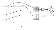
- FIG. 1 is a diagram showing an example of the configuration of an automatic analysis system according to a first embodiment.
- FIG. 7 is a diagram showing an example of a GUI for setting a threshold in the image processing apparatus of the first embodiment.
- FIG. 7 is a diagram for explaining the relationship between the installation state of the container and the detection range with respect to the image acquisition device of the first embodiment.
- FIG. 7 is a diagram for explaining the relationship between the installation state of the container and the detection range with respect to the image acquisition device of the first embodiment.
- FIG. 2 is a diagram illustrating an example of a hardware configuration and a software configuration of an image processing apparatus according to a first embodiment.
- FIG. 8 is a diagram showing the concept of the Convolution process performed by the feature quantity calculation unit of the first embodiment.
- FIG. 8 is a diagram showing the concept of Pooling processing executed by the feature quantity calculation unit of the first embodiment.
- FIG. 7 is a view showing an example of classification of the state of the sample surface in Example 1;
- FIG. 7 is a view showing an example of classification of the state of the sample surface in Example 1;
- FIG. 7 is a view showing an example of classification of the state of the sample surface in Example 1;
- FIG. 7 is a diagram illustrating an example of supervised machine learning according to the first embodiment.
- FIG. 8 is a diagram showing an example of a process of determining the surface state of a sample performed by the image processing apparatus of the first embodiment.
- FIG. 8 is a diagram showing an example of the software configuration of the image processing apparatus of the second embodiment.
- FIG. 14 is a diagram showing an example of the image correction process of the second embodiment.
- FIG. 14 is a diagram showing an example of a process of determining the surface state of a sample performed by the image processing apparatus of the second embodiment.
- FIG. 14 is a diagram showing an example of the software configuration of the image processing apparatus of the third embodiment.
- FIG. 18 is a view showing an example of a GUI displayed by the image processing apparatus of the third embodiment. It is a flowchart explaining an example of the processing which the learning part of Example 3 performs.
- the embodiment of the present invention may be implemented by software running on a general-purpose computer, or implemented by dedicated hardware or firmware, or a combination of software and hardware and firmware. It is also good.
- each process of the present invention when each process of the present invention is described with the functional unit as the subject (action subject), it indicates that the processing unit is executing the process according to a program for realizing each functional unit.
- part or all of the program for realizing each functional unit may be realized using dedicated hardware or may be modularized.
- Various programs may be installed in the image processing apparatus by a program distribution server or storage medium.
- the apparatus determines the state of the sample surface from the position and size of the detection target (such as air bubbles) with respect to the detection range in the image based on the image of the sample surface obtained by imaging the surface of the sample container.
- the detection target such as air bubbles
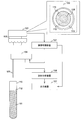
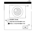
- FIG. 1 is a diagram showing an example of the configuration of the automatic analysis system of the first embodiment.
- the automatic analysis system includes an image processing apparatus 101, an illumination apparatus 102, an image acquisition apparatus 103, a sample acquisition apparatus 104, a sample analysis apparatus 106, and an output apparatus 107, and an apparatus for installing a container 110 in which a sample 111 is placed. including.
- the sample 111 is a sample to be analyzed, such as blood and urine.
- the sample surface 112 is the liquid level of the sample 111.
- the container 110 is a container such as a test tube into which the sample 111 is placed.
- the sample acquisition device 104 is a suction device having a dispensing probe or the like for suctioning the sample 111.
- the sample acquiring device 104 controls the dispensing probe 105 to acquire the sample 111 stored in the container 110.
- the illumination device 102 is a device such as an LED that emits light toward the sample surface 112 from the opening side of the container 110.
- the image acquisition apparatus 103 is an apparatus such as a camera that acquires an image of the sample surface 112 from the opening side.
- the image acquisition device 103 of this embodiment acquires an image of the sample surface 112 and outputs an image of the range indicated by the image acquisition range 120 to the image processing device 101.
- the image shown in FIG. 1 is an image of the sample surface 112 taken from the opening side of the container 110.
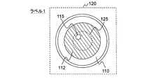
- the detection target object 115 is an object, a substance, or the like involved in acquisition control of the sample 111.
- the air bubble is the detection object 115.
- the detection range 125 is a range set in the image, and is a range in which the detection target object 115 is detected. Since the detection range 125 is a range set for the image acquisition range 120, it does not depend on the position and size of the container 110 in the image.
- the image processing device 101 determines the state of the sample surface 112 by analyzing the image input from the image acquisition device 103.
- the container 110 containing the sample 111 is placed at a predetermined position with respect to the image acquisition device 103.
- the container 110 is disposed immediately below the image acquisition device 103.
- the illumination device 102 adjusts the angle and intensity of the light so that the lightness of the sample surface 112 is appropriate.
- the image acquisition device 103 acquires an image of the sample surface 112, and outputs the acquired image to the image processing device 101. At this time, it is assumed that the sample acquisition device 104 has moved to a position that does not prevent the image acquisition by the image acquisition device 103.
- the image processing apparatus 101 determines the state of the sample surface 112 based on the position and the size of the detection target 115 with respect to the detection range 125 in the image.
- the image processing apparatus 101 outputs the determination result to the sample acquisition apparatus 104.
- the image processing apparatus 101 outputs data such as the determination result to the output device 107 as necessary.
- the image processing apparatus 101 is described as an independent computer, but may be implemented as a function in an automatic analyzer such as an immune analyzer.
- the sample acquisition device 104 determines the control content based on the determination result. Specifically, the sample acquiring device 104 determines whether to acquire the sample 111 from the container 110. If it is determined that the sample 111 is to be obtained, the sample acquisition device 104 lowers the dispensing probe 105 toward the sample 111. When the dispensing probe 105 comes in contact with the sample surface 112, the sample acquiring device 104 detects the liquid level by the liquid level detection function, and stops the descent of the dispensing probe 105. The sample acquiring apparatus 104 performs an operation such as suctioning the sample 111 in a state where the tip of the dispensing probe 105 is slightly immersed in the sample surface 112. The sample 111 is obtained from the container 110 by the above process.
- the sample analyzer 106 is a device that analyzes the sample 111 acquired by the sample acquiring device 104, and is, for example, an immune analyzer or the like.
- the sample analyzer 106 outputs the analysis result to the output device 107.
- the output device 107 is a device that presents the analysis result to the user, and is, for example, a display, a printer, and a communication device.
- the output device 107 also presents the information output from the image processing apparatus 101 to the user.
- the apparatus when determining the presence or absence of a detection target, calculates the center coordinates of the container boundary or opening based on Hough transformation etc. and detects the vicinity of the center of the container opening Set to range.
- the process of calculating the center coordinates of the opening of the container is a factor that increases the processing cost and the processing time. Therefore, in order to reduce the processing cost and the processing time, it is desirable to determine the position and size of the detection target without calculating the center coordinates of the opening of the container.
- the image processing apparatus 101 of this embodiment detects the relative positional relationship between the detection range 125 and the detection object 115 independent of the position and size of the container 110 in the image, and the size and detection of the detection range 125.
- the state of the sample surface 112 is determined based on the relative size relationship between the size of the object 115.
- a detection range 125 and a threshold of the size of the detection object 115 which does not affect analysis are set.
- the size of the detection object 115 is one of the indicators for determining whether or not the analysis is affected, the size of the detection object 115 also needs to be considered. For example, it is conceivable to set the maximum radius of the detection object 115 which does not affect the analysis as a threshold.
- the threshold may be set by the user using a GUI.
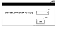
- FIG. 2 is a diagram illustrating an example of a GUI for setting a threshold in the image processing apparatus 101 according to the first embodiment.
- the GUI 200 includes a threshold input field 201 and a determination button 202.
- the threshold input field 201 is a field for inputting a value to be set as the threshold.
- the determination button 202 is an operation button for setting the value input in the threshold value input field 201 to the image processing apparatus 101.
- the user sets a value or the like indicating the maximum radius of the air bubble in the threshold value input field 201, and presses the determination button 202.
- the threshold is set in the image processing apparatus 101.
- the GUI 200 illustrated in FIG. 2 is an example, and an input field for setting the detection range 125 and the image acquisition range 120 may be provided.
- options such as processing time and processing load may be displayed.
- a threshold value corresponding to the option is set in the image processing apparatus 101.
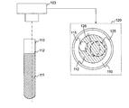
- FIGS. 3A and 3B are diagrams for explaining the relationship between the installation state of the container 110 and the detection range 125 with respect to the image acquisition device 103 of the first embodiment.
- the image acquisition range 120 indicates the range of the image to be output to the image processing apparatus 101.
- the image acquisition range 120 is set to be larger than the container 110 in consideration of the displacement of the installation position of the container 110 and the like.
- the image of the image acquisition range 120 includes the container 110, the sample surface 112, and the detection object 115.
- a detection range 125 is set for the image acquisition range 120.
- the image acquisition range 120 may not be a range including the container 110, and can be set arbitrarily.
- the image acquisition range 120 sets an area of (E ⁇ E) pixels whose origin is the center of the image.
- E which shows size of vertical and horizontal sets a larger value than the diameter of container 110.
- the detection range 125 is a range whose origin is a point at which the tip of the dispensing probe 105 is in contact with the sample surface 112, and is a range that does not depend on the central coordinates of the container 110.
- the detection range 125 is set as a circular range of radius R pixels.
- the installation angle and the installation position of the container 110 with respect to the image acquisition device 103 may change.
- the processing time and processing load can be reduced compared to the prior art.
- the detection range 125 is a detection range adopted by the present invention, and is a range of radius R pixels whose origin is a point at which the tip of the dispensing probe 105 is in contact with the sample surface 112.
- the detection range 126 is a detection range adopted in the prior art, and is a range of radius R pixels with the center of the opening of the container 110 as the origin.
- FIG. 3A shows a state in which the installation angle of the container 110 with respect to the image acquisition device 103 has changed. At this time, a gap occurs between the center of the opening of the container 110 and the center of the image acquisition range 120. Accordingly, as shown in FIG. 3A, a deviation also occurs between the detection range 125 and the detection range 126.
- the detection range 125 includes the detection target 115, but the detection range 126 does not include the detection target 115.
- the tip of the dispensing probe 105 is in contact with the inside of the detection range 125. Therefore, in the case of the state shown in FIG. 3A, it is desirable to discriminate from the state in which the detection object 115 having an influence on analysis is present.
- the determination process based on the detection range 125 When the determination process based on the detection range 125 is executed, it is determined that the detection object 115 is present. On the other hand, when the determination process based on the detection range 126 is performed, it is determined that the detection object 115 is not present. Therefore, in the determination process based on the detection range 125, the detection target object 115 can be detected accurately, but in the determination process based on the detection range 126, the detection accuracy is not improved due to the deviation as described above.
- FIG. 3B shows a state in which the installation position of the container 110 with respect to the image acquisition device 103 is changed. At this time, a gap occurs between the center of the opening of the container 110 and the center of the image acquisition range 120. Accordingly, as shown in FIG. 6B, a deviation also occurs between the detection range 125 and the detection range 126.
- the detection range 125 does not include the detection target 115, but the detection range 126 includes the detection target 115.
- the tip of the dispensing probe 105 is in contact with the inside of the detection range 125. Therefore, in the case of the state shown in FIG. 3B, it is desirable to determine that there is no detected object 115 that affects the analysis.
- the determination process based on the detection range 125 When the determination process based on the detection range 125 is executed, it is determined that the detection object 115 does not exist. On the other hand, when the determination process based on the detection range 126 is performed, it is determined that the detection object 115 is present. Therefore, in the discrimination process based on the detection range 125, excessive detection of the detection object 115 can be avoided, but in the discrimination process based on the detection range 126, excessive detection of the detection object 115 occurs.
- the tilt of the container 110 and the change of the installation position occur. Even if it exists, it can be determined with high accuracy whether or not there is an influence of the detection object 115. Further, in the present embodiment, since it is not necessary to calculate the center coordinates of the opening of the container 110, the processing cost and the processing time can be reduced as compared with the prior art.
- FIG. 4 is a diagram illustrating an example of a hardware configuration and a software configuration of the image processing apparatus 101 according to the first embodiment.
- the image processing apparatus 101 includes an arithmetic unit 401, a storage unit 402, an input unit 403, and an output unit 404.
- the arithmetic device 401 is a device that executes a program stored in the storage device 402, and is, for example, a CPU, an FPGA, or the like.
- the arithmetic device 401 operates as a functional unit (module) that realizes a predetermined function by executing processing according to a program.
- a functional unit module
- the arithmetic device 401 is executing a program for realizing the functional unit.
- each functional unit included in the image processing apparatus 101 a plurality of functional units may be combined into one functional unit, or one functional unit may be divided into a plurality of functional units.
- the storage device 402 is a device that stores a program executed by the computing device 401 and information used by the program, and, for example, a memory, a hard disk drive (HDD), a solid state drive (SSD), and a random access memory (RAM). , And ROM (Read Only Memory).
- the storage device 402 includes a work area temporarily used by the program. The programs and information stored in the storage device 402 will be described later.
- the input device 403 is a device for inputting data to the image processing apparatus 101, and is, for example, a network interface or a keyboard, a mouse, and a touch panel. In the present embodiment, an image acquired by the image acquisition device 103 is input via the input device 403.
- the input image may be a still image such as BMP, PNG, and JPEG, or may be MPEG, H.264, or the like. It may be a frame image extracted at regular intervals from a moving image such as H.264.
- the output device 404 is a device for the image processing device 101 to output data, and is, for example, a network interface or a display or a printer. In the present embodiment, the determination result is output to the sample acquiring device 104 via the output device 404.
- the storage device 402 stores programs for realizing the image input unit 411, the feature quantity calculation unit 412, the sample state determination unit 413, and the storage unit 414.
- the image input unit 411 receives an image input through the input device 403, and outputs the image to the feature amount calculation unit 412.
- the feature amount calculation unit 412 calculates an image feature amount from the image, and outputs the image feature amount to the sample state determination unit 413.
- the sample state determination unit 413 analyzes the position and size of the detection target with respect to the detection range in the image based on the image feature amount, and determines the state of the sample surface 112 based on the analysis result.
- the storage unit 414 stores information of a discriminant model for discriminating the state of the sample surface 112. Specifically, the storage unit 414 stores the coefficients used by the feature quantity calculation unit 412 and the sample state determination unit 413.
- the feature amount calculation unit 412 reads the coefficient from the storage unit 414, and calculates an image feature amount using the coefficient and the image.
- the coefficients used by the feature quantity calculation unit 412 are derived in advance based on machine learning or the like, and stored in the storage unit 414. The method of deriving the coefficient will be described later.
- CNN convolutional neural network
- FIG. 5 is a diagram illustrating the concept of the Convolution process performed by the feature quantity calculation unit 412 according to the first embodiment.
- the feature amount calculation unit 412 calculates a feature amount using Equation (1). Note that, as shown by the arrows, the calculation of equation (1) is executed in the direction from the upper left to the lower right of the image.
- Ic is input data
- Wc is a multiplication coefficient
- Bc is an addition coefficient
- Oc is output data.
- ch represents a channel
- y and fy represent vertical positions
- x and fx represent horizontal positions
- d represents a feature number.
- the input data Ic is data having dimensions of channel ch, vertical position y, and horizontal position x.
- the multiplication coefficient Wc is a coefficient having dimensions of feature amount number d, channel ch, vertical position fy, and horizontal position fx.
- the addition coefficient Bc is a coefficient having the dimension of the feature amount number d.
- the output data 303 is data having dimensions of feature amount number d, vertical position y, and horizontal position x.
- the multiplication coefficient Wc and the addition coefficient Bc are coefficients for calculating the image feature amount, and the storage unit 414 stores the multiplication coefficient Wc and the addition coefficient Bc.
- FIG. 6 is a diagram illustrating the concept of the Pooling process performed by the feature quantity calculation unit 412 according to the first embodiment.
- the feature quantity calculation unit 412 extracts partial areas of the output data Oc from upper left to lower right with a constant step width, calculates representative values from the partial areas, and outputs output data Op. .
- a representative value for example, a maximum value or an average value is used.
- the feature quantity calculating unit 412 executes arithmetic processing using a non-linear function such as a tanh function shown in equation (2) or a ReLU function shown in equation (3) on the output data Op.
- a non-linear function such as a tanh function shown in equation (2) or a ReLU function shown in equation (3)
- the output data Op is input to x.
- an image feature quantity is calculated by repeatedly executing the convolution process, the pooling process, and the activation process.
- the feature quantity calculation unit 412 reaches the specified number, the feature quantity calculation unit 412 outputs the value calculated by the final activation process as an image feature quantity.
- the sample state determination unit 413 uses the image feature amount calculated by the feature amount calculation unit 412 and the coefficient stored in the storage unit 414 to determine the position and size of the detection target object 115 with respect to the detection range 125 in the image.
- the analysis is performed to determine the state of the sample surface 112 based on the analysis result.
- the sample state determination unit 413 classifies to which of the states set in advance the input image belongs.
- the coefficients used by the sample state determination unit 413 are derived in advance based on machine learning or the like, and stored in the storage unit 414. The method of deriving the coefficient will be described later.
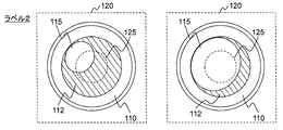
- 7A, 7B, and 7C are diagrams showing an example of classification of the state of the sample surface 112 in the first embodiment.
- the states are roughly classified into a state in which the detection target 115 that affects the analysis is present in the detection range 125 and a state in which the detection target 115 that affects the analysis is not in the detection range 125.
- the state of the sample surface 112 is classified into three based on the relationship between the position and the size of the detection object 115 with respect to the detection range 125 in the image, in consideration of the state identification accuracy. Label 0, label 1 and label 2 are given to each state.
- FIG. 7A shows an example of an image of label 0.
- the detection object 115 does not exist in the detection range 125.
- FIG. 7B shows an example of the image of label 1.
- a detection target object 115 having a radius d1 smaller than the threshold D is present in the detection range 125. That is, the detection target object 115 having a size not affecting analysis is present in the detection range 125.
- FIG. 7C shows an example of the image of the label 2.
- the detection object 115 having the radius d2 equal to or larger than the threshold D is present in the image on the left side.
- a detection object 115 having a radius d3 equal to or larger than the threshold D is present so as to cover the detection range 125. That is, the detection target object 115 having a size that affects the analysis is present in the detection range 125.
- the state of the sample surface 112 of label 0 and label 1 is included in the absence of the detection object 115 that affects the analysis in the detection range 125, and the sample surface 112 of label 2 is the detection range 125.
- the detection object 115 which affects the analysis is included.
- the state of the sample surface 112 to be classified is determined in accordance with the position and the size of the detection object 115 with respect to the detection range 125 in the image.
- a label (teacher signal) corresponding to the state of the sample surface 112 is attached to the learning image.
- the sample acquiring device 104 when classified into label 0 or label 1, the sample acquiring device 104 is controlled to acquire the sample 111, and when the image is classified into label 2, the sample acquiring device 104 acquires the sample. Not to be controlled.
- Expression (4) is an expression used in Logistic Regression.
- Formula (5) shows the calculation method of the softmax function of Formula (4).
- P (c) is an output value
- F is an image feature amount
- Wr is a multiplication coefficient
- Br is an addition coefficient
- y represents a vertical position
- x represents a horizontal position
- d represents a feature number
- c represents an output unit number.
- the output unit number corresponds to label 0, label 1 and label 2.
- P (c) is a value representing the likelihood of the label corresponding to the output unit.
- the image feature amount F is data having dimensions of a feature amount number d, a vertical position y, and a horizontal position x.
- the multiplication factor Wr is a factor having dimensions of an output unit number c, a feature amount number d, a vertical position y, and a horizontal position x.
- the addition coefficient Br is a coefficient having the dimension of the output unit number c.
- the output value P (c) is a value having the dimension of the output unit number c.
- the multiplication coefficient Wr and the addition coefficient Br are coefficients for calculating the determination result, and the storage unit 414 stores the multiplication coefficient Wr and the addition coefficient Br.
- the sample state determination unit 413 outputs, as an output signal P, a set P (c) of likelihoods of three labels.
- the likelihood of each label is a value calculated based on Expression (4).
- the sample state determination unit 413 specifies which label state the state of the sample surface 112 corresponds to, based on the output signal P. That is, the position and the size of the detection object 115 with respect to the detection range 125 are analyzed. Furthermore, the sample state determination unit 413 outputs the determination result based on the state of the identified label. For example, the sample state determination unit 413 outputs a label as a determination result. Further, the sample state determination unit 413 may determine whether the sample surface 112 can obtain the sample 111 based on the label.
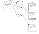
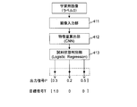
- FIG. 8 is a diagram illustrating an example of supervised machine learning according to the first embodiment.
- a device having a learning unit in advance receives an input of learning data (learning image) to which a teacher signal is added, causes the feature amount calculating unit 412 and the sample state determining unit 413 to execute processing, and outputs
- the discriminator or the like is trained so that the signal matches the target signal corresponding to the teacher signal (label).
- the respective coefficients of Equation (1) and Equation (4) are optimized based on supervised learning. By this, it is possible to set a coefficient for obtaining a highly accurate determination result for the input image.
- the apparatus having the learning unit may include the same configuration as the feature quantity calculating unit 412 and the sample state determining unit 413.
- a teacher signal (label) is learned beforehand It is necessary to give to the image for.
- the initial value of the coefficient before the start of the learning process may be set arbitrarily using a random number or the like, or may be set based on the previous learning process.
- the learning unit derives coefficients to be stored in the storage unit 414 according to the following process.
- Step S1 The learning unit receives an input of a learning image with a teacher signal, and obtains an output signal by inputting to the feature amount calculating unit 412 and the sample state determining unit 413.
- the learning unit defines an objective function of the output signal and the target signal shown in equation (6). Equation (6) represents negative log likelihood.
- T (c) represents an element of the target signal.
- the target signal T in the present embodiment is an array of T (c) representing target values of three labels.
- the value of each element of the target signal T only the element corresponding to the label is "1.0", and all other elements are "0.0".
- the learning image to which the label 0 is assigned is input, only the T (c) corresponding to the label 0 is “1.0”, and the target signal T is T corresponding to the other label. All (c) is "0.0".
- the learning unit may hold the same function as the feature amount calculation unit 412 and the sample state determination unit 413.
- Step S2 The learning unit updates the coefficients Wc, Bc, Wr, and Br by obtaining a coefficient with which the value of the target function becomes a minimum value using a gradient descent method. Specifically, the coefficients are updated according to equation (7).
- w i represents a coefficient corresponding to one of CNN coefficients Wc and Bc and Logistic Regression coefficients Wr and Br. i represents the number of updates. Further, ⁇ represents a learning rate which is a parameter for determining the width of updating.
- the second term of equation (7) is the partial derivative of the coefficient w i .
- the learning unit derives the coefficients Wc, Bc, Wr, and Br which minimize the target function by repeatedly executing the arithmetic processing based on the equation (7).
- the coefficients derived by the above processing are stored in advance in the storage unit 414.
- FIG. 9 is a diagram illustrating an example of the process of determining the surface state of the sample 111 performed by the image processing apparatus 101 according to the first embodiment.
- the image input unit 411 of the image processing apparatus 101 receives an input of an image from the image acquisition apparatus 103 (step S901).
- the feature quantity calculation unit 412 of the image processing apparatus 101 reads the coefficients Wc and Bc from the storage unit 414, and calculates an image feature quantity using the image and the coefficients (step S902).
- the sample state determination unit 413 of the image processing apparatus 101 reads the coefficients Wr and Br from the storage unit 414, and outputs an output signal using the image feature amount and the coefficient (step S903). Furthermore, the sample state determination unit 413 determines the state of the sample surface 112 based on the output signal (step S904).
- the sample state determination unit 413 of the image processing apparatus 101 outputs the determination result (step S905).
- the sample state determination unit 413 may output the determination result as it is, or may convert the data format and content of the determination result according to the output destination. For example, when the output destination is a display, the sample state determination unit 413 converts data such as a character string and an image.
- the state of the sample surface 112 is the state of the label 2
- control is performed so that acquisition of the sample 111 is not performed
- the present invention is not limited thereto.
- the sample acquiring apparatus 104 has an apparatus or function for removing the detection object 115 and the discrimination result indicating the label 2 is input
- the detection object 115 is removed using the apparatus or function, and then The sample 111 may be obtained.
- an apparatus which removes the detection target object 115 there exist a removal apparatus, such as a nozzle etc. which discharges air, a removal apparatus which irradiates an ultrasonic wave.
- calculation method of the image feature-value based on CNN was demonstrated as a calculation method of an image feature-value
- calculation method of other feature-values such as HOG (Histograms of Oriented Gradients) and circle detection by Hough transformation, may be used.
- the determination method was demonstrated using Logistic Regression as a determination method of the state of the sample surface 112, the determination method using SVM (Support Vector Machine), a linear regression, etc. may be used.
- SVM Small Vector Machine
- size of the detection target object 115 with respect to the detection range 125 in an image it is not limited to this.
- a label for classifying the position of the detection object 115 with respect to the detection range 125 in the image and a label for classifying the size of the detection object 115 may be prepared.
- the sample state determination unit 413 has a classifier that determines labels of different types.
- the coefficients stored in the storage unit 414 are calculated by performing machine learning on each label.
- the sample state determination unit 413 can obtain the final determination result by combining the determination results of the two classifiers.
- multiple thresholds may be defined for the position or size of the detection object 115 relative to the detection range 125 in the image to increase the type or number of labels. Further, the number of labels may be reduced by treating the label 0, the label 1 and the like as the same label.
- the determination result of the image processing apparatus 101 is used for control of the sample acquisition apparatus 104 or is not limited to this.
- the determination result of the image processing apparatus 101 can be used as information for determining the contents of various controls related to analysis of a sample.
- the image processing apparatus 101 can also be applied to systems other than the automatic analysis system as shown in FIG.
- the image processing apparatus 101 can accurately determine the state of the sample surface 112 based on the position and the size of the detection target 115 with respect to the detection range 125 in the image. .
- the sample 111 to be analyzed can be efficiently and accurately obtained from the container 110, accurate analysis of the sample 111 can be performed without lowering the inspection efficiency.
- the image processing apparatus 101 corrects the image input from the image acquisition apparatus 103, and executes the same processing as the first embodiment using the corrected image.
- the second embodiment will be described focusing on the difference from the first embodiment.
- the configuration of the system of the second embodiment is the same as the configuration of the system of the first embodiment.
- the hardware configuration of the image processing apparatus 101 of the second embodiment is the same as the hardware configuration of the image processing apparatus 101 of the first embodiment.
- the software configuration of the image processing apparatus 101 is partially different.
- FIG. 10 is a diagram illustrating an example of the software configuration of the image processing apparatus 101 according to the second embodiment.
- the second embodiment differs from the first embodiment in that a program for realizing the image correction unit 1001 is stored in the storage device 402.
- the second embodiment is different from the first embodiment in that the storage unit 414 stores parameters used by the image correction unit 1001.
- the image input unit 411, the feature amount calculation unit 412, and the sample state determination unit 413 are the same as those in the first embodiment.
- the image correction unit 1001 When the image correction unit 1001 receives an image from the image input unit 411, the image correction unit 1001 reads a parameter from the storage unit 414 and executes an image correction process.
- the image correction processing includes coordinate conversion, pixel value normalization, and the like.
- FIG. 11 is a diagram illustrating an example of the image correction process according to the second embodiment.
- FIG. 11 shows the result in the case of performing polar coordinate conversion on the left image of FIG. 7C.
- the detection range 125 is circular, in order to determine whether or not the detection object 115 is included in the detection range 125 in Cartesian coordinates, it is necessary to determine from each position in the vertical direction and the horizontal direction. On the other hand, when polar coordinate conversion is performed, the detection range 125 is expressed as a rectangle, and whether or not the detection object 115 is included in the detection range 125 can be determined only from the position in the vertical direction.
- equation (8) and equation (9) holds between the pixel position (x, y) in orthogonal coordinates and the pixel position (t, r) in polar coordinates.
- rStep represents a step size in the radial direction
- tStep represents a step size in the declination direction.
- (Cy, Cx) are coordinates in the image which is the origin of polar coordinate conversion, and here, are central coordinates of the detection range 125.
- parameters used for image correction processing such as a radial step size rStep used for polar coordinate conversion and a variable angle direction step size tStep, are stored.
- FIG. 12 is a diagram illustrating an example of the process of determining the surface state of the sample 111 performed by the image processing apparatus 101 according to the second embodiment.
- the image correction unit 1001 of the image processing apparatus 101 reads a parameter from the storage unit 414, executes an image correction process, and calculates a corrected image (step S1201).
- the image correction unit 1001 outputs a corrected image to the feature amount calculation unit 412.
- step S902 the feature amount calculation unit 412 is different from the first embodiment in that the process described in the first embodiment is performed on the corrected image.
- the processes in steps S901 and S903 to S905 are the same as those in the first embodiment.
- polar coordinate conversion has been described as an example of image correction processing, coordinate conversion other than polar coordinate conversion, processing for normalizing average values and dispersion values of luminance and hue, contrast enhancement processing, edge enhancement processing, or these It may be a process combining.
- the second embodiment by executing the image correction process, it is possible to improve the accuracy of the image processing and to reduce the calculation amount. For example, the position of the detection target 115 with respect to the detection range 125 in the image can be grasped more accurately and efficiently.
- the third embodiment differs from the first embodiment in that the coefficients are periodically or sequentially updated using an image acquired at the time of analysis as a new learning image.
- the third embodiment will be described below focusing on the difference from the first embodiment.
- the configuration of the system of the third embodiment is the same as the configuration of the system of the first embodiment.
- the hardware configuration of the image processing apparatus 101 of the third embodiment is the same as the hardware configuration of the image processing apparatus 101 of the first embodiment.
- the software configuration of the image processing apparatus 101 is partially different.
- FIG. 13 is a diagram illustrating an example of the software configuration of the image processing apparatus 101 according to the third embodiment.
- FIG. 14 is a diagram illustrating an example of a GUI displayed by the image processing apparatus 101 according to the third embodiment.
- the third embodiment differs from the first embodiment in that programs for realizing the user operation input unit 1301, the learning unit 1302, and the image display unit 1303 are stored in the storage device 402.
- the third embodiment is different from the first embodiment in that an image or the like acquired at the time of analysis is stored in the storage unit 414.
- the image input unit 411 stores the input image in the storage unit 414.
- the sample state determination unit 413 also stores the output signal in the storage unit 414.
- the storage unit 414 manages the image in which the determination of the sample state has been performed and the output signal corresponding to the image in association with each other.
- the image display unit 1303 generates display information for presenting the image selected by the learning unit 1302 to the user, and outputs the display information via the output device 404. Based on the output information, a GUI 1400 as shown in FIG. 14 is displayed.
- the GUI 1400 includes an image display field 1401, a teacher signal selection field 1402, and a decision button 1403.
- the GUI 1400 may include display fields other than those described above.
- a display field may be included to present supplementary information.
- the area indicating the detection range 125 is presented as supplementary information.
- the image display field 1401 is a field for displaying the image selected by the learning unit 1302.
- the teacher signal selection field 1402 is a field for selecting a teacher signal to be added to the image.
- the top radio button is a button for designating a teacher signal corresponding to label 0.
- the radio button in the middle is a button for designating a teacher signal corresponding to the label 1.
- the lowermost radio button is a button for specifying a teacher signal corresponding to the label 2.
- the determination button 1403 is an operation button for outputting operation information including the value input to the teacher signal selection field 1402.
- the user operation input unit 1301 receives operation information output by operating the GUI 1400, and generates a teacher signal corresponding to the image presented on the GUI 1400. For example, when the bottom radio button of the teacher signal selection field 1402 is operated, the user operation input unit 1301 generates a teacher signal of label 2.
- the learning unit 1302 selects an image to be presented to the user from the images stored in the storage unit 414 at the time of analysis, and outputs the selected image to the image display unit 1303. Also, the learning unit 1302 associates the selected image with the teacher signal input from the user operation input unit 1301 and stores the associated image in the storage unit 414. Furthermore, the learning unit 1302 updates the coefficients (discrimination model) stored in the storage unit 414 by executing machine learning using an image with a teacher signal.
- step S 901 the image input unit 411 stores the image in the storage unit 414.
- step S904 the sample state determination unit 413 stores the output signal in the storage unit 414.
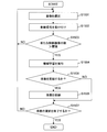
- FIG. 15 is a flowchart illustrating an example of processing performed by the learning unit 1302 according to the third embodiment.
- the learning unit 1302 selects an image to be presented to the user from among the images stored in the storage unit 414 (step S1501).
- the learning unit 1302 outputs the selected image to the image display unit 1303.
- a method of selecting an image for example, there is a method of selecting an image with the smallest difference between the maximum likelihood and the minimum likelihood of the output signal calculated by the sample state determination unit 413.
- the likelihoods are normalized so that the sum of all likelihoods is 1.0 by the softmax function. Therefore, in the case of an image that is difficult to classify, the difference between the maximum likelihood and the minimum likelihood decreases. Therefore, the discrimination accuracy can be efficiently improved by presenting such an image to the user and inputting it as a new learning image.
- the learning unit 1302 receives a teacher signal from the user operation input unit 1301 (step S1502).
- the learning unit 1302 adds a teacher signal to the selected image, and stores the image as a new learning image in the storage unit 414.
- the image processing apparatus 101 can collect a new learning image by repeatedly executing presentation of an image and acceptance of operation information.
- step S1503 determines whether the number of newly stored learning images is larger than a threshold.
- the process of step S1503 is a process for detecting an opportunity to newly execute machine learning. Therefore, other determination methods may be used. For example, machine learning may be performed when an execution instruction is received from a user or when a predetermined time has elapsed.
- the learning unit 1302 If it is determined that the number of newly stored learning images is equal to or less than the threshold value, the learning unit 1302 returns to step S1501 and executes the same processing.
- the learning unit 1302 executes machine learning using the new learning images (step S1504).
- the machine learning is performed by the same method as the process described in the first embodiment.
- a new coefficient is calculated as an execution result of machine learning.
- the learning unit 1302 determines whether to update the coefficient (step S1505). Specifically, the learning unit 1302 evaluates the calculated coefficient according to an arbitrary evaluation method, and determines whether the coefficient is stored in the storage unit 414 or not.
- the learning unit 1302 calculates the determination accuracy of the image with a correct answer when a new coefficient is used. If the determination accuracy is larger than the threshold, the learning unit 1302 determines to update the coefficient.
- step S1507 If it is determined that the coefficient is not updated, the learning unit 1302 proceeds to step S1507.
- the learning unit 1302 stores the new coefficient in the storage unit 414 (step S1506).
- the learning unit 1302 overwrites the coefficient newly stored in the coefficient stored in the storage unit 414.
- the learning unit 1302 may store the coefficient before updating and the coefficient newly calculated in the storage unit 414. In this case, coefficients to be used may be selected according to the user operation.
- step S1505 After the determination result in step S1505 is NO, or after the process in step S1506, the learning unit 1302 determines whether to end updating the coefficient (step S1507).
- the learning unit 1302 determines to end the updating of the coefficient.
- the learning unit 1302 returns to step S1501 and executes the same process.
- the learning unit 1302 ends the process.
- the feature quantity calculation unit 412 and the sample state determination unit 413 may immediately read the updated coefficient, or may read the updated coefficient when actually processing.
- the learning unit 1302 uses the image acquired at the time of analysis as a new learning image, it may store the learning image with a basic teaching signal in the storage unit 414 in advance.
- the learning unit 1302 determines whether to automatically update the coefficient based on an evaluation result obtained using an arbitrary evaluation method, but the present invention is not limited to this.
- the learning unit 1302 may present the evaluation result to the user, and make the user determine whether to update the coefficient.
- the teacher signal to be assigned to the new learning image has been manually selected by the user, but is not limited to this.
- the learning unit 1302 or the like determines a label corresponding to the output unit with the largest likelihood among the likelihoods included in the output signal as a temporary teacher signal, and presents a temporary teacher signal and an image to the user, The user may correct the temporary teacher signal. At this time, if there is no correction for a certain period of time from the presentation of the image, the learning unit 1302 may adopt a method of adopting it as a formal teacher signal.
- the state of the sample surface 112 can be determined using the coefficient corresponding to the apparatus and the environment, so that the determination accuracy can be improved.
- the present invention can also be realized by a program code of software that realizes the functions of the embodiment.
- a storage medium storing the program code is provided to the system or apparatus, and a computer (or CPU and MPU) of the system or apparatus reads the program code stored in the storage medium.
- the program code itself read from the storage medium implements the functions of the above-described embodiments, and the program code itself and the storage medium storing the same constitute the present invention.
- a storage medium for supplying such a program code for example, a flexible disk, a CD-ROM, a DVD-ROM, a hard disk, an optical disk, an optical magnetic disk, a CD-R, a magnetic tape, a non-volatile memory card, a ROM Etc. are used.
- an OS Operating System
- the CPU of the computer or the like performs part or all of the actual processing based on the instruction of the program code, and the processing.
- the storage means such as a hard disk or memory of a system or apparatus or a storage medium such as a CD-RW or CD-R
- the computer (or CPU or MPU) of the system or apparatus may read out and execute the program code stored in the storage means or the storage medium at the time of use.
- control lines and the information lines indicate what is considered necessary for the description, and not all the control lines and the information lines in the product are necessarily shown. All configurations may be connected to each other.
Landscapes
- Engineering & Computer Science (AREA)
- Chemical & Material Sciences (AREA)
- Physics & Mathematics (AREA)
- General Physics & Mathematics (AREA)
- Life Sciences & Earth Sciences (AREA)
- Health & Medical Sciences (AREA)
- Theoretical Computer Science (AREA)
- Computer Vision & Pattern Recognition (AREA)
- Analytical Chemistry (AREA)
- Biochemistry (AREA)
- General Health & Medical Sciences (AREA)
- Bioinformatics & Cheminformatics (AREA)
- Software Systems (AREA)
- General Engineering & Computer Science (AREA)
- Pathology (AREA)
- Wood Science & Technology (AREA)
- Immunology (AREA)
- Biotechnology (AREA)
- Organic Chemistry (AREA)
- Zoology (AREA)
- Evolutionary Computation (AREA)
- Medical Informatics (AREA)
- Artificial Intelligence (AREA)
- Computing Systems (AREA)
- Quality & Reliability (AREA)
- Mathematical Physics (AREA)
- Data Mining & Analysis (AREA)
- Biomedical Technology (AREA)
- Sustainable Development (AREA)
- Microbiology (AREA)
- Genetics & Genomics (AREA)
- Medicinal Chemistry (AREA)
- Image Analysis (AREA)
- Automatic Analysis And Handling Materials Therefor (AREA)
- Investigating Or Analysing Materials By Optical Means (AREA)
- Apparatus Associated With Microorganisms And Enzymes (AREA)
Priority Applications (3)
| Application Number | Priority Date | Filing Date | Title |
|---|---|---|---|
| US16/635,502 US11282184B2 (en) | 2017-07-31 | 2018-05-31 | Apparatus, method for determining state of sample, and analysis system |
| EP18840296.0A EP3663767B1 (en) | 2017-07-31 | 2018-05-31 | Apparatus, method for determing state of sample, and analysis system |
| CN201880041315.7A CN110892272B (zh) | 2017-07-31 | 2018-05-31 | 装置、试料的状态的判别方法以及分析系统 |
Applications Claiming Priority (2)
| Application Number | Priority Date | Filing Date | Title |
|---|---|---|---|
| JP2017-147629 | 2017-07-31 | ||
| JP2017147629A JP7011904B2 (ja) | 2017-07-31 | 2017-07-31 | 装置、試料における気泡の状態の判別方法、及び分析システム |
Publications (1)
| Publication Number | Publication Date |
|---|---|
| WO2019026406A1 true WO2019026406A1 (ja) | 2019-02-07 |
Family
ID=65233578
Family Applications (1)
| Application Number | Title | Priority Date | Filing Date |
|---|---|---|---|
| PCT/JP2018/020952 Ceased WO2019026406A1 (ja) | 2017-07-31 | 2018-05-31 | 装置、試料の状態の判別方法、及び分析システム |
Country Status (5)
| Country | Link |
|---|---|
| US (1) | US11282184B2 (enExample) |
| EP (1) | EP3663767B1 (enExample) |
| JP (1) | JP7011904B2 (enExample) |
| CN (1) | CN110892272B (enExample) |
| WO (1) | WO2019026406A1 (enExample) |
Families Citing this family (8)
| Publication number | Priority date | Publication date | Assignee | Title |
|---|---|---|---|---|
| JP7273542B2 (ja) * | 2019-03-01 | 2023-05-15 | 富士レビオ株式会社 | 分析装置、検体前処理装置、訓練装置、プログラム、情報処理方法、学習モデルおよび学習モデルの生成方法 |
| JP7320972B2 (ja) * | 2019-04-08 | 2023-08-04 | 株式会社日立ハイテク | 画像処理装置、自動分析システム及び画像処理方法 |
| KR102255346B1 (ko) * | 2019-12-17 | 2021-05-25 | 주식회사 포스코 | 인공신경망 학습을 통한 시료의 분석방법 및 분석장치 |
| US11145397B1 (en) | 2020-01-31 | 2021-10-12 | Express Scripts Strategie Development, Inc. | System and method for augmented reality detection of loose pharmacy items |
| JP7353198B2 (ja) | 2020-02-06 | 2023-09-29 | 株式会社日立ハイテク | 計算機、識別器の学習方法、および分析システム |
| EP3979131A1 (en) | 2020-10-02 | 2022-04-06 | Roche Diagnostics GmbH | A method for determining at least one state of at least one cavity of a transport interface configured for transporting sample tubes |
| EP4270301A4 (en) | 2020-12-25 | 2024-01-24 | Mitsubishi Electric Corporation | OBJECT DETECTION DEVICE, MONITORING DEVICE, LEARNING DEVICE AND MODEL GENERATION METHOD |
| US20230394696A1 (en) * | 2022-06-02 | 2023-12-07 | University Of Central Florida Research Foundation, Inc. | Systems and methods for image-based characterization of fluid in an enclosed container |
Citations (8)
| Publication number | Priority date | Publication date | Assignee | Title |
|---|---|---|---|---|
| JP2007309888A (ja) * | 2006-05-22 | 2007-11-29 | Olympus Corp | 分注装置 |
| JP2008275473A (ja) * | 2007-04-27 | 2008-11-13 | Olympus Corp | 分析装置および分析方法 |
| JP2013088114A (ja) * | 2011-10-13 | 2013-05-13 | Hitachi High-Technologies Corp | 液面状態検出装置、自動分析装置および液面状態検出方法 |
| US20130315486A1 (en) | 2010-11-16 | 2013-11-28 | Roche Diagnostics Operations, Inc. | Method and apparatus for detecting foam on a liquid surface in a vessel |
| JP2016510211A (ja) | 2012-12-20 | 2016-04-07 | スリーエム イノベイティブ プロパティズ カンパニー | ガス産生微生物のコロニーの検出方法 |
| JP2016085572A (ja) * | 2014-10-24 | 2016-05-19 | 朝一 村上 | ビール評価用プログラム、コンピュータ及びビール評価方法 |
| WO2016121449A1 (ja) * | 2015-01-28 | 2016-08-04 | 株式会社 日立ハイテクノロジーズ | 液面検査装置、自動分析装置および処理装置 |
| JP2017147629A (ja) | 2016-02-18 | 2017-08-24 | 三菱重工業株式会社 | 駐車位置検出システム及びそれを用いた自動駐車システム |
Family Cites Families (13)
| Publication number | Priority date | Publication date | Assignee | Title |
|---|---|---|---|---|
| CH448566A (de) * | 1965-05-05 | 1967-12-15 | Ceskoslovenska Akademie Ved | Optische Einrichtung zum Auswerten von Konzentrationsgradienten in durch kapillare Leitungen von Analysatoren strömenden Flüssigkeiten |
| JP2548383B2 (ja) * | 1989-06-23 | 1996-10-30 | アロカ株式会社 | 液状試料中の気泡の検出方法及びその装置 |
| JP2564628Y2 (ja) * | 1991-08-01 | 1998-03-09 | 東亞医用電子株式会社 | 試薬分取装置における泡検知装置 |
| EP0913671A1 (de) * | 1997-10-29 | 1999-05-06 | Roche Diagnostics GmbH | Verfahren und Vorrichtung zum Flüssigkeitstransfer mit einem Analysegerät |
| US6582929B2 (en) * | 2001-04-24 | 2003-06-24 | Dade Microscan Inc. | Method for minimizing optical interference during antibiotic susceptibility readings in a microbiological analyzer |
| AU2009217355A1 (en) * | 2008-02-21 | 2009-08-27 | Avantra Biosciences Corporation | Assays based on liquid flow over arrays |
| CN101859378B (zh) * | 2010-06-11 | 2012-09-12 | 湖南大学 | 高速医药生产线上的药液质量视觉检测方法 |
| JP5941692B2 (ja) | 2012-02-13 | 2016-06-29 | 株式会社日立ハイテクノロジーズ | 自動分析装置 |
| EP3076183B1 (en) * | 2013-11-26 | 2021-06-30 | Hitachi High-Tech Corporation | Automatic analyzer |
| CN105793714B (zh) * | 2014-01-27 | 2018-02-23 | 株式会社日立高新技术 | 自动分析装置 |
| US10288637B2 (en) * | 2014-05-15 | 2019-05-14 | Hitachi High-Technologies Corporation | Automatic analyzer |
| ES2898649T3 (es) * | 2015-07-13 | 2022-03-08 | Siemens Healthcare Diagnostics Products Gmbh | Procedimiento para el pipeteo de líquidos en un aparato analizador automático |
| CN105067641A (zh) * | 2015-07-16 | 2015-11-18 | 东华大学 | 基于模板粒子群寻优的复杂体异物的微波检测系统 |
-
2017
- 2017-07-31 JP JP2017147629A patent/JP7011904B2/ja active Active
-
2018
- 2018-05-31 EP EP18840296.0A patent/EP3663767B1/en active Active
- 2018-05-31 WO PCT/JP2018/020952 patent/WO2019026406A1/ja not_active Ceased
- 2018-05-31 US US16/635,502 patent/US11282184B2/en active Active
- 2018-05-31 CN CN201880041315.7A patent/CN110892272B/zh active Active
Patent Citations (9)
| Publication number | Priority date | Publication date | Assignee | Title |
|---|---|---|---|---|
| JP2007309888A (ja) * | 2006-05-22 | 2007-11-29 | Olympus Corp | 分注装置 |
| JP2008275473A (ja) * | 2007-04-27 | 2008-11-13 | Olympus Corp | 分析装置および分析方法 |
| US20130315486A1 (en) | 2010-11-16 | 2013-11-28 | Roche Diagnostics Operations, Inc. | Method and apparatus for detecting foam on a liquid surface in a vessel |
| JP2014500955A (ja) * | 2010-11-16 | 2014-01-16 | エフ.ホフマン−ラ ロシュ アーゲー | 容器内の液面上の泡を検出する方法および装置 |
| JP2013088114A (ja) * | 2011-10-13 | 2013-05-13 | Hitachi High-Technologies Corp | 液面状態検出装置、自動分析装置および液面状態検出方法 |
| JP2016510211A (ja) | 2012-12-20 | 2016-04-07 | スリーエム イノベイティブ プロパティズ カンパニー | ガス産生微生物のコロニーの検出方法 |
| JP2016085572A (ja) * | 2014-10-24 | 2016-05-19 | 朝一 村上 | ビール評価用プログラム、コンピュータ及びビール評価方法 |
| WO2016121449A1 (ja) * | 2015-01-28 | 2016-08-04 | 株式会社 日立ハイテクノロジーズ | 液面検査装置、自動分析装置および処理装置 |
| JP2017147629A (ja) | 2016-02-18 | 2017-08-24 | 三菱重工業株式会社 | 駐車位置検出システム及びそれを用いた自動駐車システム |
Also Published As
| Publication number | Publication date |
|---|---|
| CN110892272B (zh) | 2023-09-26 |
| US11282184B2 (en) | 2022-03-22 |
| CN110892272A (zh) | 2020-03-17 |
| EP3663767B1 (en) | 2023-07-26 |
| US20200242752A1 (en) | 2020-07-30 |
| EP3663767A1 (en) | 2020-06-10 |
| JP2019027927A (ja) | 2019-02-21 |
| JP7011904B2 (ja) | 2022-01-27 |
| EP3663767A4 (en) | 2021-04-28 |
Similar Documents
| Publication | Publication Date | Title |
|---|---|---|
| JP7011904B2 (ja) | 装置、試料における気泡の状態の判別方法、及び分析システム | |
| US12203868B2 (en) | Qualitative or quantitative characterization of a coating surface | |
| CN105849274B (zh) | 用于显微图像中的单独细胞的分类和识别的方法和系统 | |
| US10706535B2 (en) | Tissue staining quality determination | |
| JP6791864B2 (ja) | 検査室自動化のためのサイドビューサンプルチューブ画像におけるバーコードタグ検出 | |
| EP4071485A1 (en) | Sample analysis system and method, cell image analyzer, and storage medium | |
| US10395091B2 (en) | Image processing apparatus, image processing method, and storage medium identifying cell candidate area | |
| CN114585443B (zh) | 训练诊断分析仪模型的设备和方法 | |
| JP7320972B2 (ja) | 画像処理装置、自動分析システム及び画像処理方法 | |
| US12190616B2 (en) | Cell counting or cell confluence with rescaled input images | |
| JPWO2018207261A1 (ja) | 画像解析装置 | |
| CN110503705A (zh) | 图像标注方法和设备 | |
| KR20240089449A (ko) | 교사 데이터 작성 지원 장치, 교사 데이터 작성 지원 방법 | |
| CN114585926A (zh) | 标识管组件类型的设备和方法 | |
| EP4545976A1 (en) | Sample condition assessing device, sample condition assessing method, and sample testing device | |
| CN117132640A (zh) | 血清的检测方法、装置、血样检测设备及计算机存储介质 | |
| KR20250138608A (ko) | 컨포멀 코팅의 미세 기포 검출을 위한 최적 uv 조도 선정 방법 및 이를 이용한 기포 검사 장치 | |
| JP2025049901A (ja) | 試料状態判定装置、試料状態判定方法、および試料分析システム | |
| US20190383724A1 (en) | Image processing device, cell recognition apparatus, cell recognition method, and cell recognition program | |
| KR20230171892A (ko) | 의료 정보를 추출하는 장치 및 방법 | |
| HK40068330A (en) | Apparatus and methods of identifying tube assembly type | |
| CN114155277A (zh) | 一种基于视频目标追踪的微流体分析方法及装置 | |
| HK40068364A (en) | Apparatus and methods of training models of diagnostic analyzers |
Legal Events
| Date | Code | Title | Description |
|---|---|---|---|
| 121 | Ep: the epo has been informed by wipo that ep was designated in this application |
Ref document number: 18840296 Country of ref document: EP Kind code of ref document: A1 |
|
| NENP | Non-entry into the national phase |
Ref country code: DE |
|
| ENP | Entry into the national phase |
Ref document number: 2018840296 Country of ref document: EP Effective date: 20200302 |