WO2019024894A1 - 一种游戏手柄的控制方法、存储介质及游戏手柄 - Google Patents
一种游戏手柄的控制方法、存储介质及游戏手柄 Download PDFInfo
- Publication number
- WO2019024894A1 WO2019024894A1 PCT/CN2018/098356 CN2018098356W WO2019024894A1 WO 2019024894 A1 WO2019024894 A1 WO 2019024894A1 CN 2018098356 W CN2018098356 W CN 2018098356W WO 2019024894 A1 WO2019024894 A1 WO 2019024894A1
- Authority
- WO
- WIPO (PCT)
- Prior art keywords
- level signal
- module
- pin
- resistor
- signal
- Prior art date
- Legal status (The legal status is an assumption and is not a legal conclusion. Google has not performed a legal analysis and makes no representation as to the accuracy of the status listed.)
- Ceased
Links
Images



Classifications
-
- A—HUMAN NECESSITIES
- A63—SPORTS; GAMES; AMUSEMENTS
- A63F—CARD, BOARD, OR ROULETTE GAMES; INDOOR GAMES USING SMALL MOVING PLAYING BODIES; VIDEO GAMES; GAMES NOT OTHERWISE PROVIDED FOR
- A63F13/00—Video games, i.e. games using an electronically generated display having two or more dimensions
- A63F13/20—Input arrangements for video game devices
- A63F13/21—Input arrangements for video game devices characterised by their sensors, purposes or types
-
- A—HUMAN NECESSITIES
- A63—SPORTS; GAMES; AMUSEMENTS
- A63F—CARD, BOARD, OR ROULETTE GAMES; INDOOR GAMES USING SMALL MOVING PLAYING BODIES; VIDEO GAMES; GAMES NOT OTHERWISE PROVIDED FOR
- A63F13/00—Video games, i.e. games using an electronically generated display having two or more dimensions
- A63F13/20—Input arrangements for video game devices
- A63F13/24—Constructional details thereof, e.g. game controllers with detachable joystick handles
-
- A—HUMAN NECESSITIES
- A63—SPORTS; GAMES; AMUSEMENTS
- A63F—CARD, BOARD, OR ROULETTE GAMES; INDOOR GAMES USING SMALL MOVING PLAYING BODIES; VIDEO GAMES; GAMES NOT OTHERWISE PROVIDED FOR
- A63F2300/00—Features of games using an electronically generated display having two or more dimensions, e.g. on a television screen, showing representations related to the game
- A63F2300/10—Features of games using an electronically generated display having two or more dimensions, e.g. on a television screen, showing representations related to the game characterized by input arrangements for converting player-generated signals into game device control signals
Definitions
- the present application relates to the field of game device technologies, and in particular, to a game controller control method, a storage medium, and a game controller.
- the game controller is the core link of the whole control game. It is the most direct interaction with the human hand, and it is also the most control of the game. Direct action point. Therefore, during the whole game, if you want to use the state of the handlebar to handle other things, or handle other things to the game state, you need to press the "pause” or "continue” button to increase the operation. , inconvenience to the user's use.
- the embodiment of the present application provides a method for controlling a game controller, a storage medium, and a game controller, which can solve the problem that the operation of the existing game controller requires manual control of the pause/resume button.
- an embodiment of the present application provides a method for controlling a game controller, wherein a surface of the game controller is provided with a sensor; and the method includes:
- the sensor collects a first sensing signal when a human hand approaches the game handle
- the step of generating a low-level signal according to the first sensing signal to control the opening of the game controller according to the low-level signal further includes:
- a first timer is started to record the duration of the first sensing signal.
- the step of generating a low level signal according to the first sensing signal to control the opening of the game handle according to the low level signal is specifically as follows:
- the duration of the first sensing signal is greater than a preset time threshold, generating a low level signal according to the first sensing signal to control the gamepad to be turned on according to the low level signal.
- the method further includes:
- the sensor collects the second sensing signal when the hand is away from the game handle, and records the duration of the second sensing signal by the second timer;
- the duration of the second sensing signal is greater than the preset time threshold, a high level signal is generated and the gamepad pause is controlled according to the high level signal.
- control circuit is disposed in the sensor, and a low level signal/high level signal is generated by the control circuit.
- the control circuit includes a main control module, an input module, an output module, an antistatic module, a filtering module, and an adjustment module; and the input module passes the sensing signal through the antistatic
- the module performs anti-static and the filtering module filters the input to the main control module; the main control module generates a level signal carrying the control signal according to the sensing signal, and outputs a level signal carrying the control signal to the An adjustment module, the adjustment module modulates a voltage of the level signal according to the control signal, outputs a low level signal to the output module, and outputs the output module.
- the antistatic module includes a TVS tube, and one end of the TVS tube is connected between the input module and the filter module, and the other end is grounded.
- an embodiment of the present application provides a storage medium storing a plurality of instructions, the instructions being adapted to be loaded by a processor and performing the following steps:
- the sensor collects a first sensing signal when the hand is near the game handle; wherein the sensor is disposed on a surface of the game handle;
- the sensor collects a second sensing signal when the hand is away from the game handle
- a high level signal is generated according to the second sensing signal, and the gamepad pause is controlled according to the high level signal.
- the step of generating a low level signal according to the first sensing signal to control the opening of the game handle according to the low level signal comprises:
- the duration of the first sensing signal is greater than a preset time threshold, generating a low level signal according to the first sensing signal to control the gamepad to be turned on according to the low level signal.
- the step of generating a high level signal according to the second sensing signal and controlling the pause of the game handle according to the high level signal comprises:
- a second timer is started, the second timer recording a duration of the second sensing signal
- the duration of the second sensing signal is greater than the preset time threshold, a high level signal is generated and the gamepad pause is controlled according to the high level signal.
- an embodiment of the present application provides a gamepad, including:
- a storage device adapted to store a plurality of instructions adapted to be loaded by the processor and to perform the following steps:
- the charge in the sensing antenna of the sensor changes, and the capacitance value of the sensing antenna changes to obtain the first sensing signal
- the charge in the sensing antenna of the sensor is changed, thereby causing a change in the capacitance value of the sensing antenna to obtain a second sensing signal
- a high level signal is generated according to the second sensing signal, and the gamepad pause is controlled according to the high level signal.
- the step of generating a low level signal according to the first sensing signal to control the opening of the game handle according to the low level signal comprises:
- the duration of the first sensing signal is greater than a preset time threshold, generating a low level signal according to the first sensing signal to control the gamepad to be turned on according to the low level signal.
- the step of generating a high level signal according to the second sensing signal and controlling the pause of the game handle according to the high level signal comprises:
- a second timer is started, the second timer recording a duration of the second sensing signal
- the duration of the second sensing signal is greater than the preset time threshold, a high level signal is generated and the gamepad pause is controlled according to the high level signal.
- the senor comprises an inductive antenna and a control circuit.
- the sensor includes a first sensor and a second sensor
- the first sensor is disposed on one of the handles of the game handle
- the second sensor is disposed on the game handle On the other handle.
- the control circuit includes a main control module, an input module, an output module, an antistatic module, a filtering module, and an adjustment module; and the sensing signal is sent by the input module through the antistatic module.
- the anti-static and the filtering module are filtered and input to the main control module; the main control module generates a level signal carrying the control signal according to the sensing signal, and outputs a level signal carrying the control signal to the adjustment module.
- the adjusting module modulates the voltage of the level signal according to the control signal, outputs a low level signal to the output module, and outputs the output module.
- the input module comprises an input terminal
- the output module comprises two output terminals, the two output terminals are respectively a PSENSOR output terminal and a FPIO7 PSENSOR output terminal
- the main control module adopts a setting
- the TIMER pin, the CRXO pin, the VDDHI pin, and the VRFG pin are respectively connected to the filter module, and the THRO pin and the THRI pin are respectively connected to the adjustment module
- the CRXO pin is respectively connected to the input module and the anti-proof
- the first OUT pin is respectively connected to the adjustment module and the PSENSOR output terminal
- the second OUT pin is respectively connected to the adjustment module and the FPIO7 PSENSOR output terminal
- the VSS pin and the GND pin are respectively grounded.
- the filter module includes a first resistor R1, a second resistor R2, a first capacitor C1, a second capacitor C2, a third capacitor C3, a fourth capacitor C4, and a fifth capacitor C5;
- the first resistor R1 is connected to the TIMER;
- the second resistor R2 is connected to the CRXO pin at one end, and the antistatic module and the input terminal are respectively connected to the other end;
- the first capacitor C1 is connected to the VDDHI pin at one end and grounded at the other end;
- One end of the second capacitor C2 is connected to the VDDHI pin, and the other end is grounded;
- one end of the third capacitor C3 is connected to the CRXO pin, and the other end is grounded;
- one end of the fourth capacitor and the fifth capacitor are respectively connected to the VREG pin. The other end is grounded separately.
- the antistatic module includes a TVS tube, and one end of the TVS tube is respectively connected to the input terminal and the second resistor R2, and the other end is grounded.
- the adjustment module includes a third resistor R3, a fourth resistor R4, a fifth resistor R5, a sixth resistor R6, a seventh resistor R7, an eighth resistor R8, and a ninth resistor R9;
- the third resistor R3 and the fourth resistor R4 are respectively connected to the THRI pin, and the fifth resistor R5 and the sixth resistor R6 are respectively connected to the THRO pin, and the third resistor R3, the fourth resistor R4, the fifth resistor R5,
- the sixth resistor R6 is used to adjust the sensitivity of the level signal;
- the seventh resistor R7 is connected to one end of the first OUT pin and the ninth resistor R9, and the other end of the ninth resistor R9 is connected to the PSENSOR output terminal, One end of the eight resistor R8 is connected to the FPIO7 PSENSOR output terminal and the second out pin, and the other end is grounded;
- the seventh resistor R7, the eighth resistor R8 and the ninth resistor R9 are used to adjust the level
- the present application provides a method for controlling a gamepad, a storage medium, and a gamepad.
- the method includes: when a human hand approaches the gamepad, the sensor collects a first sensing signal; and generates according to the first sensing signal. A low level signal to control the gamepad to be turned on according to the low level signal.
- the application sets a sensor on the game handle, and the sensor senses the proximity/departure of the human hand to obtain corresponding sensing information, and generates a corresponding level signal according to the sensing information to control the opening/pausing of the game controller.
- the automatic control according to the state of the human hand simplifies the operation steps and brings convenience to the user.
- FIG. 1 is a flowchart of an embodiment of a method for controlling a game controller provided by the present application.
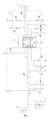
- FIG. 2 is a circuit diagram of a control circuit in a method of controlling a game controller provided by the present application.
- FIG. 3 is a schematic structural diagram of a game controller provided by the present application.
- FIG. 4 is a schematic structural diagram of a game controller provided by the present application.
- the present application provides a method for controlling a game controller, a storage medium, and a game controller.
- the objects, technical solutions, and effects of the present application will become more apparent and clear, and the present application will be further described in detail below with reference to the accompanying drawings. It is understood that the specific embodiments described herein are merely illustrative of the application and are not intended to be limiting.
- FIG. 1 is a flowchart of an embodiment of a method for controlling a gamepad provided by the present application.
- the control method of the game controller includes:
- the sensor collects the first sensing signal
- the embodiment provides a method for controlling a game controller.
- a sensor on the game handle sensing a human hand approaching/leaving by a sensor to obtain corresponding sensing information, and generating a corresponding level signal according to the sensing information to control the game controller.
- Open/pause which realizes automatic control according to the state of the human hand, simplifies the operation steps and brings convenience to the user.
- the sensor is a sensing device that is previously provided on the gamepad for detecting human body information.
- the sensor comprises an inductive antenna and a control circuit, the inductive antenna is connected to the control circuit through a wire, the control circuit is connected with the main controller of the game controller, and the high level/low level signal generated according to the sensing signal is sent to the main controller So that the master controls the gamepad on/off according to the high/low level signal.
- the sensing antennas are two, respectively disposed on the two handles of the game handle, and are in contact with the human hand when the handle is held by the human hand.
- the sensor can adopt the IQS229 model sensor, as shown in FIG. 2, the sensor control circuit includes a main control module 40, an input module 10, an output module 60, an antistatic module 20, a filter module 30, and an adjustment module 50; 10, the sensing signal is filtered by the anti-static module 20 and subjected to filtering by the anti-static and filtering module 30, and then input to the main control module 40.
- the main control module 40 generates a level signal carrying the control signal according to the sensing signal, and outputs the level of the carrying control signal.
- the signal is sent to the adjustment module 50.
- the adjustment module 50 modulates the voltage of the level signal according to the control signal, outputs a low level signal to the output module 60, and outputs it through the output module 60.
- the input module includes an input terminal
- the output module includes two output terminals
- the two output terminals are respectively a PSENSOR output terminal and an FPIO7 PSENSOR output terminal
- the main control module 40 can include a TIMER pin, a VSS pin, and a CRXO.
- the VDDHI pin and the VRFG pin are respectively connected to the filter module 30, and the THRO pin and the THRI pin are respectively connected to the adjustment module 50;
- the CRXO pin is respectively connected to the input module 10 and the antistatic module 20;
- the first OUT pin is respectively connected to the adjustment module 50.
- the second OUT pin is connected to the adjustment module 50 and the FPIO7 PSENSOR output terminal, respectively, and the VSS pin and the GND pin are grounded respectively.
- the filter module 30 includes a first resistor R1, a second resistor R2, a first capacitor C1, a second capacitor C2, a third capacitor C3, a fourth capacitor C4, and a fifth capacitor C5;
- the first resistor R1 is connected to the TIMER;
- the second resistor One end of R2 is connected to the CRXO pin, and the other end is connected to the antistatic module 20 and the input terminal respectively;
- the first capacitor C1 is connected to the VDDHI pin at one end and the other end is grounded;
- the second capacitor C2 is connected to the VDDHI pin at one end, and the other end is grounded;
- One end of C3 is connected to the CRXO pin, and the other end is grounded.
- One end of the fourth capacitor and the fifth capacitor are respectively connected to the VREG pin, and the other ends are respectively grounded.
- the antistatic module 20 includes a TVS tube. One end of the TVS tube is respectively connected to the input terminal and the second resistor R2, and the other end is grounded.
- the adjustment module 50 includes a third resistor R3, a fourth resistor R4, a fifth resistor R5, a sixth resistor R6, a seventh resistor R7, an eighth resistor R8, and a ninth resistor R9; the third resistor R3 and the fourth resistor R4 are respectively connected The THRI pin, the fifth resistor R5 and the sixth resistor R6 are respectively connected to the THRO pin, and the third resistor R3, the fourth resistor R4, the fifth resistor R5, and the sixth resistor R6 are used to adjust the sensitivity of the level signal; the seventh resistor R7 is connected to the first OUT pin and one end of the ninth resistor R9, the other end of the ninth resistor R9 is connected to the PSENSOR output terminal, and the eighth resistor R8 is connected at one end to the FPIO7 PSENSOR output terminal and the second out pin, and the other end is grounded; The resistor R7, the eighth resistor R8, and the ninth resistor R9 are used to adjust the level of the level signal.
- step S200 generating a low level signal according to the first sensing signal means that the sensing antenna generates a sensing capacitance change according to the detected charge change, and the capacitance change is used as the first sensing signal, and the capacitance change is passed through the control circuit.
- the input terminal inputs a control circuit, and the control circuit generates a high voltage signal according to the change of the capacitance, outputs a low level signal to the main controller of the game controller according to the high voltage signal, and controls the game controller to be turned on by the main controller.
- the duration of the first sensing signal may be monitored after detecting the first sensing signal, and the duration is compared with the preset time threshold, only when the duration is When the preset time threshold is greater than the preset time threshold, a level signal is generated to control the opening of the game handle, so that the human body can only avoid the wrong operation caused by the game controller.
- control method of the game controller includes:
- the sensor collects the first sensing signal
- the charge in the sensing antenna tends to balance, and the induced current disappears, and a second sensing signal is generated to control the gamepad pause.
- control method of the game controller includes:
- the sensor collects the second sensing signal, and records the duration of the second sensing signal by using the second timer.
- the preset time threshold configured by the second timer may be the same as the preset time threshold configured by the first timer, or may be different.
- the preset time thresholds configured by the two are the same, and the same control circuit is used for the control of the sensing signals, which will not be described here.
- the application also provides a storage medium storing a plurality of instructions adapted to be loaded by a processor and to perform the method as described above.
- the application also provides a gamepad, as described in FIG. 3, which includes:
- the processor 100 is adapted to implement each instruction
- the storage device 200 is adapted to store a plurality of instructions adapted to be loaded by the processor and to perform the method as described above.
- the instructions are adapted to be loaded by the processor and perform the following steps:
- the charge in the sensing antenna of the sensor changes, and the capacitance value of the sensing antenna changes to obtain the first sensing signal
- the charge in the sensing antenna of the sensor is changed, thereby causing a change in the capacitance value of the sensing antenna to obtain a second sensing signal
- a high level signal is generated according to the second sensing signal, and the gamepad pause is controlled according to the high level signal.
- the step of generating a low level signal according to the first sensing signal to control the opening of the game handle according to the low level signal comprises:
- the duration of the first sensing signal is greater than a preset time threshold, generating a low level signal according to the first sensing signal to control the gamepad to be turned on according to the low level signal.
- the step of generating a high level signal according to the second sensing signal and controlling the pause of the game handle according to the high level signal comprises:
- a second timer is started, the second timer recording a duration of the second sensing signal
- the duration of the second sensing signal is greater than the preset time threshold, a high level signal is generated and the gamepad pause is controlled according to the high level signal.
- the senor comprises an inductive antenna and a control circuit.
- the sensor includes a first sensor and a second sensor
- the first sensor is disposed on one of the handles of the game handle
- the second sensor is disposed on the game handle On the other handle.
- the control circuit includes a main control module, an input module, an output module, an antistatic module, a filtering module, and an adjustment module; and the sensing signal is sent by the input module through the antistatic module.
- the anti-static and the filtering module are filtered and input to the main control module; the main control module generates a level signal carrying the control signal according to the sensing signal, and outputs a level signal carrying the control signal to the adjustment module.
- the adjusting module modulates the voltage of the level signal according to the control signal, outputs a low level signal to the output module, and outputs the output module.
- the input module comprises an input terminal
- the output module comprises two output terminals, the two output terminals are respectively a PSENSOR output terminal and a FPIO7 PSENSOR output terminal
- the main control module adopts a setting
- the TIMER pin, the CRXO pin, the VDDHI pin, and the VRFG pin are respectively connected to the filter module, and the THRO pin and the THRI pin are respectively connected to the adjustment module
- the CRXO pin is respectively connected to the input module and the anti-proof
- the first OUT pin is respectively connected to the adjustment module and the PSENSOR output terminal
- the second OUT pin is respectively connected to the adjustment module and the FPIO7 PSENSOR output terminal
- the VSS pin and the GND pin are respectively grounded.
- the filter module includes a first resistor R1, a second resistor R2, a first capacitor C1, a second capacitor C2, a third capacitor C3, a fourth capacitor C4, and a fifth capacitor C5;
- the first resistor R1 is connected to the TIMER;
- the second resistor R2 is connected to the CRXO pin at one end, and the antistatic module and the input terminal are respectively connected to the other end;
- the first capacitor C1 is connected to the VDDHI pin at one end and grounded at the other end;
- One end of the second capacitor C2 is connected to the VDDHI pin, and the other end is grounded;
- one end of the third capacitor C3 is connected to the CRXO pin, and the other end is grounded;
- one end of the fourth capacitor and the fifth capacitor are respectively connected to the VREG pin. The other end is grounded separately.
- the antistatic module includes a TVS tube, and one end of the TVS tube is respectively connected to the input terminal and the second resistor R2, and the other end is grounded.
- the adjustment module includes a third resistor R3, a fourth resistor R4, a fifth resistor R5, a sixth resistor R6, a seventh resistor R7, an eighth resistor R8, and a ninth resistor R9;
- the third resistor R3 and the fourth resistor R4 are respectively connected to the THRI pin, and the fifth resistor R5 and the sixth resistor R6 are respectively connected to the THRO pin, and the third resistor R3, the fourth resistor R4, the fifth resistor R5,
- the sixth resistor R6 is used to adjust the sensitivity of the level signal;
- the seventh resistor R7 is connected to one end of the first OUT pin and the ninth resistor R9, and the other end of the ninth resistor R9 is connected to the PSENSOR output terminal, One end of the eight resistor R8 is connected to the FPIO7 PSENSOR output terminal and the second out pin, and the other end is grounded;
- the seventh resistor R7, the eighth resistor R8 and the ninth resistor R9 are used to adjust the level
- a sensor 11 is respectively disposed on the hand lever of the game handle, and the sensor 11 detects the approach/away of the human hand.
- the disclosed method may be implemented in other manners.
- the device embodiments described above are merely illustrative.
- the division of the modules is only a logical function division.
- there may be another division manner for example, multiple units or components may be combined or Can be integrated into another system, or some features can be ignored or not executed.
- the mutual coupling or direct coupling or communication connection shown or discussed may be an indirect coupling or communication connection through some interface, device or unit, and may be in an electrical, mechanical or other form.
- the units described as separate components may or may not be physically separated, and the components displayed as units may or may not be physical units, that is, may be located in one place, or may be distributed to multiple network units. Some or all of the units may be selected according to actual needs to achieve the purpose of the solution of the embodiment.
- each functional unit in each embodiment of the present application may be integrated into one processing unit, or each unit may exist physically separately, or two or more units may be integrated into one unit.
- the above integrated unit can be implemented in the form of hardware or in the form of hardware plus software functional units.
- the above-described integrated unit implemented in the form of a software functional unit can be stored in a computer readable storage medium.
- the software functional unit described above is stored in a storage medium and includes instructions for causing a computer device (which may be a personal computer, a server, or a network device, etc.) or a processor to perform the methods described in various embodiments of the present application. Part of the steps.
- the foregoing storage medium includes: a U disk, a mobile hard disk, a read-only memory (ROM), a random access memory (RAM), a magnetic disk, or an optical disk, and the like, which can store program codes. .
Landscapes
- Engineering & Computer Science (AREA)
- Multimedia (AREA)
- Human Computer Interaction (AREA)
- Electronic Switches (AREA)
- User Interface Of Digital Computer (AREA)
Abstract
一种游戏手柄的控制方法、存储介质及游戏手柄,该方法包括:当人手靠近游戏手柄时,传感器(11)采集第一感应信号;根据第一感应信号生成低电平信号,以根据低电平信号控制游戏手柄开启。
Description
本申请要求于2017年08月03日提交中国专利局、申请号为201710656381.2、发明名称为“一种游戏手柄的控制方法、存储介质及游戏手柄”的中国专利申请的优先权,其全部内容通过引用结合在本申请中。
本申请涉及游戏装置技术领域,特别涉及一种游戏手柄的控制方法、存储介质及游戏手柄。
随着人们生活水平的提高,传统的游戏正越来越向精细化及智能化方向发展,游戏手柄作为整个控制游戏的核心环节,是跟人手作为最直接交互的环节,也是人手控制游戏的最直接作用点。从而在整个游戏过程中,如果想用手从紧握手柄的状态到处理其他事情状态,或从处理其他事情状态到游戏状态,需要先按下“暂停”或“继续”按键,增加了操作环节,给用户的使用带来不便。
因而现有技术还有待改进和提高。
发明内容
本申请实施例提供一种游戏手柄的控制方法、存储介质及游戏手柄,能够解决现有游戏手柄需要手动控制的暂停/继续按键造成的操作繁琐的问题。
第一方面,本申请实施例提供一种游戏手柄的控制方法,其中,所述游戏手柄的表面设置有传感器;所述方法包括:
当人手靠近所述游戏手柄时,所述传感器采集第一感应信号;
根据所述第一感应信号生成低电平信号,以根据所述低电平信号控制游戏手柄开启。
所述游戏手柄的控制方法中,其中,所述根据所述第一感应信号生成低电平信号,以根据所述低电平信号控制游戏手柄开启的步骤之前,还包括:
启动第一计时器,记录所述第一感应信号的持续时间。
所述游戏手柄的控制方法中,其中,所述根据所述第一感应信号生成低电平信 号,以根据所述低电平信号控制游戏手柄开启的步骤,具体为:
当所述第一感应信号的持续时间大于预设时间阈值时,根据所述第一感应信号生成低电平信号,以根据所述低电平信号控制游戏手柄开启。
所述游戏手柄的控制方法中,其中,所述方法还包括:
当人手远离所述游戏手柄时,所述传感器采集第二感应信号,并通过第二计时器记录所述第二感应信号的持续时间;
当所述第二感应信号的持续时间大于预设时间阈值时,生成高电平信号并根据所述高电平信号控制游戏手柄暂停。
所述游戏手柄的控制方法中,其中,所述传感器内设置有控制电路,并通过所述控制电路生成低电平信号/高电平信号。
所述游戏手柄的控制方法中,其中,所述控制电路包括主控模块、输入模块、输出模块、防静电模块、滤波模块、调节模块;由所述输入模块将感应信号,经过所述防静电模块进行防静电及所述滤波模块进行滤波后输入至所述主控模块;所述主控模块根据所述感应信号生成携带控制信号的电平信号,输出携带控制信号的电平信号至所述调节模块,所述调节模块根据控制信号对电平信号的电压进行调制,输出低电平信号至所述输出模块,并经过所述输出模块输出。
所述游戏手柄的控制方法中,其中,所述防静电模块包括一TVS管,所述TVS管一端连接所述输入模块与所述滤波模块之间,另一端接地。
第二方面,本申请实施例提供一种存储介质,其存储有多条指令,所述指令适于由处理器加载并执行如下步骤:
当人手靠近游戏手柄时,传感器采集第一感应信号;其中,在所述游戏手柄的表面设置有所述传感器;
根据所述第一感应信号生成低电平信号,以根据所述低电平信号控制游戏手柄开启;
当人手远离所述游戏手柄时,所述传感器采集第二感应信号;
根据所述第二感应信号生成高电平信号,并根据所述高电平信号控制游戏手柄暂停。
所述存储介质中,其中,所述根据所述第一感应信号生成低电平信号,以根据所述低电平信号控制游戏手柄开启的步骤,包括:
启动第一计时器,记录所述第一感应信号的持续时间;
当所述第一感应信号的持续时间大于预设时间阈值时,根据所述第一感应信号生成低电平信号,以根据所述低电平信号控制游戏手柄开启。
所述存储介质中,其中,所述根据所述第二感应信号生成高电平信号,并根据所述高电平信号控制游戏手柄暂停的步骤,包括:
启动第二计时器,所述第二计时器记录所述第二感应信号的持续时间;
当所述第二感应信号的持续时间大于预设时间阈值时,生成高电平信号并根据所述高电平信号控制游戏手柄暂停。
第三方面,本申请实施例提供一种游戏手柄,其包括:
处理器,适于实现各指令;以及
存储设备,适于存储多条指令,所述指令适于由处理器加载并执行如下步骤:
当人手靠近游戏手柄时,引起传感器的感应天线内的电荷发生变化,进而引起感应天线电容值变化而得到第一感应信号;
根据所述第一感应信号生成低电平信号,以根据所述低电平信号控制游戏手柄开启;
当人手远离所述游戏手柄时,引起传感器的感应天线内的电荷发生变化,进而引起感应天线电容值变化而得到第二感应信号;
根据所述第二感应信号生成高电平信号,并根据所述高电平信号控制游戏手柄暂停。
在所述游戏手柄中,其中,所述根据所述第一感应信号生成低电平信号,以根据所述低电平信号控制游戏手柄开启的步骤,包括:
启动第一计时器,记录所述第一感应信号的持续时间;
当所述第一感应信号的持续时间大于预设时间阈值时,根据所述第一感应信号生成低电平信号,以根据所述低电平信号控制游戏手柄开启。
在所述游戏手柄中,其中,所述根据所述第二感应信号生成高电平信号,并根据所述高电平信号控制游戏手柄暂停的步骤,包括:
启动第二计时器,所述第二计时器记录所述第二感应信号的持续时间;
当所述第二感应信号的持续时间大于预设时间阈值时,生成高电平信号并根据所述高电平信号控制游戏手柄暂停。
在所述游戏手柄中,其中,所述传感器包括感应天线和控制电路。
在所述游戏手柄中,其中,所述传感器包括第一传感器和第二传感器,所述第一传感器设置在所述游戏手柄的其中一个手柄上,所述第二传感器设置在所述游戏手柄的另一个手柄上。
在所述游戏手柄中,其中,所述控制电路包括主控模块、输入模块、输出模块、防静电模块、滤波模块、调节模块;由所述输入模块将感应信号,经过所述防静电模块进行防静电及所述滤波模块进行滤波后输入至所述主控模块;所述主控模块根据所述感应信号生成携带控制信号的电平信号,输出携带控制信号的电平信号至所述调节模块,所述调节模块根据控制信号对电平信号的电压进行调制,输出低电平信号至所述输出模块,并经过所述输出模块输出。
在所述游戏手柄中,其中,所述输入模块包括输入端子,所述输出模块包括两个输出端子,两个输出端子分别为PSENSOR输出端子和FPIO7 PSENSOR输出端子;所述主控模块采用包括设置有TIMER引脚、VSS引脚、CRXO引脚、VDDHI引脚、VREG引脚、THRI引脚、MOV THR引脚、THRO引脚、第一OUT引脚、第二OUT引脚以及GND引脚的主芯片;所述TIMER引脚、CRXO引脚、VDDHI引脚及VRFG引脚分别连接滤波模块,所述THRO引脚和THRI引脚分别连接调节模块;所述CRXO引脚分别连接输入模块和防静电模块;所述第一OUT引脚分别连接调节模块和PSENSOR输出端子;所述第二OUT引脚分别连接调节模块和FPIO7 PSENSOR输出端子,所述VSS引脚和GND引脚分别接地。
在所述游戏手柄中,其中,所述滤波模块包括第一电阻R1、第二电阻R2、第一电容C1、第二电容C2、第三电容C3、第四电容C4以及第五电容C5;所述第一电阻R1与所述TIMER连接;所述第二电阻R2一端连接CRXO引脚,另一端分别连接防静电模块和输入端子;所述第一电容C1一端连接VDDHI引脚,另一端接地;所述第二电容C2一端连接VDDHI引脚,另一端接地;所述第三电容C3一端连接CRXO引脚,另一端接地;所述第四电容和第五电容的一端分别与VREG引 脚相连接,另一端分别接地。
在所述游戏手柄中,其中,所述防静电模块包括一TVS管,所述TVS管一端分别连接输入端子和第二电阻R2,另一端接地。
在所述游戏手柄中,其中,所述调节模块包括第三电阻R3、第四电阻R4、第五电阻R5、第六电阻R6、第七电阻R7、第八电阻R8和第九电阻R9;所述第三电阻R3和第四电阻R4分别连接THRI引脚,所述第五电阻R5和第六电阻R6分别连接THRO引脚,所述第三电阻R3、第四电阻R4、第五电阻R5、第六电阻R6用于调节电平信号的灵敏度;所述第七电阻R7连接第一OUT引脚和第九电阻R9的一端,所述第九电阻R9的另一端连接PSENSOR输出端子,所述第八电阻R8一端连接FPIO7 PSENSOR输出端子和第二out引脚,另一端接地;所述第七电阻R7、第八电阻R8和第九电阻R9用于调整电平信号的电平。
有益效果:本申请提供了一种游戏手柄的控制方法、存储介质及游戏手柄,所述方法包括:当人手靠近所述游戏手柄时,传感器采集第一感应信号;根据所述第一感应信号生成低电平信号,以根据所述低电平信号控制游戏手柄开启。本申请通过在游戏手柄上设置传感器,通过所述传感器感应人手接近/离开以得到相应的感应信息,并根据所述感应信息生成相应的电平信号,以控制所述游戏手柄开启/暂停,实现了根据人手的状态自动控制,简化了操作步骤,给用户的使用带来方便。
发明概述
对附图的简要说明
图1为本申请提供的游戏手柄的控制方法实施例的流程图。
图2为本申请提供的游戏手柄的控制方法中控制电路的电路图。
图3为本申请提供的一种游戏手柄的结构原理图。
图4为本申请提供的一种游戏手柄的结构示意图。
本申请提供一种游戏手柄的控制方法、存储介质及游戏手柄,为使本申请的目的、技术方案及效果更加清楚、明确,以下参照附图并举实施例对本申请进一 步详细说明。应当理解,此处所描述的具体实施例仅用以解释本申请,并不用于限定本申请。
本技术领域技术人员可以理解,除非特意声明,这里使用的单数形式“一”、“一个”、“所述”和“该”也可包括复数形式。应该进一步理解的是,本申请的说明书中使用的措辞“包括”是指存在所述特征、整数、步骤、操作、元件和/或组件,但是并不排除存在或添加一个或多个其他特征、整数、步骤、操作、元件、组件和/或它们的组。应该理解,当我们称元件被“连接”或“耦接”到另一元件时,它可以直接连接或耦接到其他元件,或者也可以存在中间元件。此外,这里使用的“连接”或“耦接”可以包括无线连接或无线耦接。这里使用的措辞“和/或”包括一个或更多个相关联的列出项的全部或任一单元和全部组合。
本技术领域技术人员可以理解,除非另外定义,这里使用的所有术语(包括技术术语和科学术语),具有与本申请所属领域中的普通技术人员的一般理解相同的意义。还应该理解的是,诸如通用字典中定义的那些术语,应该被理解为具有与现有技术的上下文中的意义一致的意义,并且除非像这里一样被特定定义,否则不会用理想化或过于正式的含义来解释。
下面结合附图,通过对实施例的描述,对本申请内容作进一步说明。
请参照图1,图1为本申请提供的游戏手柄的控制方法的实施例的流程图。游戏手柄的控制方法包括:
S100、当人手靠近游戏手柄时,传感器采集第一感应信号;
S200、根据第一感应信号生成低电平信号,以根据低电平信号控制游戏手柄开启。
本实施例提供了一种游戏手柄的控制方法,通过在游戏手柄上设置传感器,通过传感器感应人手接近/离开以得到相应的感应信息,并根据感应信息生成相应的电平信号,以控制游戏手柄开启/暂停,实现了根据人手的状态自动控制,简化了操作步骤,给用户的使用带来方便。
具体的来说,在步骤S100中,传感器为预先设置于游戏手柄上,用于检测人体信息的传感装置。传感器包括感应天线和控制电路,感应天线通过导线与控制电路相连接,控制电路与游戏手柄的主控器相连接,并将根据感应信号生成的 高电平/低电平信号发送至主控器,以使得主控器根据高电平/低电平信号控制游戏手柄开启/暂停。
当人手靠近设置于游戏手柄上的感应天线时,引起感应天线内的电荷发生变化,进而引起感应天线电容值变化而得到第一感应信号,感应天线将感应电容值变化通过导线传输至控制电路。在本实施例中,感应天线为两个,分别设置于游戏手柄的两个手柄上,并且当人手握持手柄时与人手接触。
进一步,传感器可以采用IQS229型号的传感器,如图2所示,传感器的控制电路包括主控模块40,输入模块10、输出模块60、防静电模块20、滤波模块30以及调节模块50;由输入模块10将感应信号,经过防静电模块20进行防静电及滤波模块30进行滤波后输入至主控模块40;主控模块40根据感应信号生成携带控制信号的电平信号,输出携带控制信号的电平信号至调节模块50,调节模块50根据控制信号对电平信号的电压进行调制,输出低电平信号至输出模块60,并经过输出模块60输出。
进一步,输入模块包括输入端子,输出模块包括两个输出端子,两个输出端子分别为PSENSOR输出端子和FPIO7 PSENSOR输出端子;主控模块40可以采用包括设置有TIMER引脚、VSS引脚、CRXO引脚、VDDHI引脚、VREG引脚、THRI引脚、MOV THR引脚、THRO引脚、第一OUT引脚、第二OUT引脚以及GND引脚的主芯片;TIMER引脚、CRXO引脚、VDDHI引脚及VRFG引脚分别连接滤波模块30,THRO引脚和THRI引脚分别连接调节模块50;CRXO引脚分别连接输入模块10和防静电模块20;第一OUT引脚分别连接调节模块50和PSENSOR输出端子;第二OUT引脚分别连接调节模块50和FPIO7 PSENSOR输出端子,VSS引脚和GND引脚分别接地。
滤波模块30包括第一电阻R1、第二电阻R2、第一电容C1、第二电容C2、第三电容C3、第四电容C4以及第五电容C5;第一电阻R1与TIMER连接;第二电阻R2一端连接CRXO引脚,另一端分别连接防静电模块20和输入端子;第一电容C1一端连接VDDHI引脚,另一端接地;第二电容C2一端连接VDDHI引脚,另一端接地;第三电容C3一端连接CRXO引脚,另一端接地;第四电容和第五电容的一端分别与VREG引脚相连接,另一端分别接地。
防静电模块20包括一TVS管,TVS管一端分别连接输入端子和第二电阻R2,另一端接地。
调节模块50包括第三电阻R3、第四电阻R4、第五电阻R5、第六电阻R6、第七电阻R7、第八电阻R8和第九电阻R9;第三电阻R3和第四电阻R4分别连接THRI引脚,第五电阻R5和第六电阻R6分别连接THRO引脚,第三电阻R3、第四电阻R4、第五电阻R5、第六电阻R6用于调节电平信号的灵敏度;第七电阻R7连接第一OUT引脚和第九电阻R9的一端,第九电阻R9的另一端连接PSENSOR输出端子,第八电阻R8一端连接FPIO7 PSENSOR输出端子和第二out引脚,另一端接地;第七电阻R7、第八电阻R8和第九电阻R9用于调整电平信号的电平。
进一步,在步骤S200中,根据第一感应信号生成低电平信号指的是感应天线根据检测到的电荷变化生成感应电容变化,并将电容变化作为第一感应信号,将电容变化通过控制电路的输入端子输入控制电路,控制电路根据电容变化生成高电压信号,根据高电压信号输出低电平信号至游戏手柄的主控器,通过主控器控制游戏手柄开启。
在本申请的一个实施例中,为了提供感应的准确性,在检测到第一感应信号后可以监听第一感应信号的持续时间,并将持续时间与预设时间阈值进行比较,仅当持续时间大于预设时间阈值时,生成电平信号以控制游戏手柄开启,这样可以避免人体仅是经过游戏手柄而造成的错误操作。
相应的,本实施例提供的游戏手柄的控制方法,其包括:
S11、当人手靠近游戏手柄时,传感器采集第一感应信号;
S12、启动第一计时器,记录第一感应信号的持续时间
S13、当第一计时器超时时,根据第一感应信号生成低电平信号,以根据低电平信号控制游戏手柄开启。
在本申请的另一个实施例中,当人手远离游戏手柄时,感应天线内的电荷趋于平衡,感应电流消失,此时产生第二感应信号,用于控制游戏手柄暂停。
相应的,本实施提供的游戏手柄的控制方法,其包括:
S21、当人手远离游戏手柄时,传感器采集第二感应信号,并通过第二计时器记录第二感应信号的持续时间;
S22、当第二计时器超时时,生成高电平信号并根据高电平信号控制游戏手柄暂停。
具体地,第二计时器配置的预设时间阈值可以与第一计时器配置的预设时间阈值相同,也可以不同。在本实施例中,两者配置的预设时间阈值相同,并且采用相同的控制电路进行感应信号的控制,这里就不一一说明。
本申请还提供了一种存储介质,其存储有多条指令,所述指令适于由处理器加载并执行如上任一所述的方法。
本申请还提供了一种游戏手柄,如图3所述,其包括:
处理器100,适于实现各指令;以及
存储设备200,适于存储多条指令,所述指令适于由处理器加载并执行如上任一所述的方法。
具体如下:
所述指令适于由处理器加载并执行如下步骤:
当人手靠近游戏手柄时,引起传感器的感应天线内的电荷发生变化,进而引起感应天线电容值变化而得到第一感应信号;
根据所述第一感应信号生成低电平信号,以根据所述低电平信号控制游戏手柄开启;
当人手远离所述游戏手柄时,引起传感器的感应天线内的电荷发生变化,进而引起感应天线电容值变化而得到第二感应信号;
根据所述第二感应信号生成高电平信号,并根据所述高电平信号控制游戏手柄暂停。
在所述游戏手柄中,其中,所述根据所述第一感应信号生成低电平信号,以根据所述低电平信号控制游戏手柄开启的步骤,包括:
启动第一计时器,记录所述第一感应信号的持续时间;
当所述第一感应信号的持续时间大于预设时间阈值时,根据所述第一感应信号生成低电平信号,以根据所述低电平信号控制游戏手柄开启。
在所述游戏手柄中,其中,所述根据所述第二感应信号生成高电平信号,并根据所述高电平信号控制游戏手柄暂停的步骤,包括:
启动第二计时器,所述第二计时器记录所述第二感应信号的持续时间;
当所述第二感应信号的持续时间大于预设时间阈值时,生成高电平信号并根据所述高电平信号控制游戏手柄暂停。
在所述游戏手柄中,其中,所述传感器包括感应天线和控制电路。
在所述游戏手柄中,其中,所述传感器包括第一传感器和第二传感器,所述第一传感器设置在所述游戏手柄的其中一个手柄上,所述第二传感器设置在所述游戏手柄的另一个手柄上。
在所述游戏手柄中,其中,所述控制电路包括主控模块、输入模块、输出模块、防静电模块、滤波模块、调节模块;由所述输入模块将感应信号,经过所述防静电模块进行防静电及所述滤波模块进行滤波后输入至所述主控模块;所述主控模块根据所述感应信号生成携带控制信号的电平信号,输出携带控制信号的电平信号至所述调节模块,所述调节模块根据控制信号对电平信号的电压进行调制,输出低电平信号至所述输出模块,并经过所述输出模块输出。
在所述游戏手柄中,其中,所述输入模块包括输入端子,所述输出模块包括两个输出端子,两个输出端子分别为PSENSOR输出端子和FPIO7 PSENSOR输出端子;所述主控模块采用包括设置有TIMER引脚、VSS引脚、CRXO引脚、VDDHI引脚、VREG引脚、THRI引脚、MOV THR引脚、THRO引脚、第一OUT引脚、第二OUT引脚以及GND引脚的主芯片;所述TIMER引脚、CRXO引脚、VDDHI引脚及VRFG引脚分别连接滤波模块,所述THRO引脚和THRI引脚分别连接调节模块;所述CRXO引脚分别连接输入模块和防静电模块;所述第一OUT引脚分别连接调节模块和PSENSOR输出端子;所述第二OUT引脚分别连接调节模块和FPIO7 PSENSOR输出端子,所述VSS引脚和GND引脚分别接地。
在所述游戏手柄中,其中,所述滤波模块包括第一电阻R1、第二电阻R2、第一电容C1、第二电容C2、第三电容C3、第四电容C4以及第五电容C5;所述第一电阻R1与所述TIMER连接;所述第二电阻R2一端连接CRXO引脚,另一端分别连接防静电模块和输入端子;所述第一电容C1一端连接VDDHI引脚,另一端接地;所述第二电容C2一端连接VDDHI引脚,另一端接地;所述第三电容C3一端连接CRXO引脚,另一端接地;所述第四电容和第五电容的一端分别与VREG引 脚相连接,另一端分别接地。
在所述游戏手柄中,其中,所述防静电模块包括一TVS管,所述TVS管一端分别连接输入端子和第二电阻R2,另一端接地。
在所述游戏手柄中,其中,所述调节模块包括第三电阻R3、第四电阻R4、第五电阻R5、第六电阻R6、第七电阻R7、第八电阻R8和第九电阻R9;所述第三电阻R3和第四电阻R4分别连接THRI引脚,所述第五电阻R5和第六电阻R6分别连接THRO引脚,所述第三电阻R3、第四电阻R4、第五电阻R5、第六电阻R6用于调节电平信号的灵敏度;所述第七电阻R7连接第一OUT引脚和第九电阻R9的一端,所述第九电阻R9的另一端连接PSENSOR输出端子,所述第八电阻R8一端连接FPIO7 PSENSOR输出端子和第二out引脚,另一端接地;所述第七电阻R7、第八电阻R8和第九电阻R9用于调整电平信号的电平。
进一步,如图4所示,游戏手柄的手杆上分别设置有一传感器11,通过传感器11检测人手接近/远离。
在本申请所提供的实施例中,应该理解到,所揭露的方法,可以通过其它的方式实现。例如,以上所描述的装置实施例仅仅是示意性的,例如,所述模块的划分,仅仅为一种逻辑功能划分,实际实现时可以有另外的划分方式,例如多个单元或组件可以结合或者可以集成到另一个系统,或一些特征可以忽略,或不执行。另一点,所显示或讨论的相互之间的耦合或直接耦合或通信连接可以是通过一些接口,装置或单元的间接耦合或通信连接,可以是电性,机械或其它的形式。
所述作为分离部件说明的单元可以是或者也可以不是物理上分开的,作为单元显示的部件可以是或者也可以不是物理单元,即可以位于一个地方,或者也可以分布到多个网络单元上。可以根据实际的需要选择其中的部分或者全部单元来实现本实施例方案的目的。
另外,在本申请各个实施例中的各功能单元可以集成在一个处理单元中,也可以是各个单元单独物理存在,也可以两个或两个以上单元集成在一个单元中。上述集成的单元既可以采用硬件的形式实现,也可以采用硬件加软件功能单元的形式实现。
上述以软件功能单元的形式实现的集成的单元,可以存储在一个计算机可读取存储介质中。上述软件功能单元存储在一个存储介质中,包括若干指令用以使得一台计算机设备(可以是个人计算机,服务器,或者网络设备等)或处理器(processor)执行本申请各个实施例所述方法的部分步骤。而前述的存储介质包括:U盘、移动硬盘、只读存储器(Read-Only Memory,ROM)、随机存取存储器(Random Access Memory,RAM)、磁碟或者光盘等各种可以存储程序代码的介质。
最后应说明的是:以上实施例仅用以说明本申请的技术方案,而非对其限制;尽管参照前述实施例对本申请进行了详细的说明,本领域的普通技术人员应当理解:其依然可以对前述各实施例所记载的技术方案进行修改,或者对其中部分技术特征进行等同替换;而这些修改或者替换,并不使相应技术方案的本质脱离本申请各实施例技术方案的精神和范围。
Claims (20)
- 一种游戏手柄的控制方法,其中,所述游戏手柄的表面设置有传感器;所述方法包括:当人手靠近所述游戏手柄时,所述传感器采集第一感应信号;根据所述第一感应信号生成低电平信号,以根据所述低电平信号控制游戏手柄开启。
- 根据权利要求1所述游戏手柄的控制方法,其中,所述根据所述第一感应信号生成低电平信号,以根据所述低电平信号控制游戏手柄开启的步骤之前,还包括:启动第一计时器,记录所述第一感应信号的持续时间。
- 根据权利要求2所述游戏手柄的控制方法,其中,所述根据所述第一感应信号生成低电平信号,以根据所述低电平信号控制游戏手柄开启的步骤,具体为:当所述第一感应信号的持续时间大于预设时间阈值时,根据所述第一感应信号生成低电平信号,以根据所述低电平信号控制游戏手柄开启。
- 根据权利要求1所述游戏手柄的控制方法,其中,所述方法还包括:当人手远离所述游戏手柄时,所述传感器采集第二感应信号,并通过第二计时器记录所述第二感应信号的持续时间;当所述第二感应信号的持续时间大于预设时间阈值时,生成高电平信号并根据所述高电平信号控制游戏手柄暂停。
- 根据权利要求4所述游戏手柄的控制方法,其中,所述传感器内设置有控制电路,并通过所述控制电路生成低电平信号/高电平信号。
- 根据权利要求5所述游戏手柄的控制方法,其中,所述控制电路包括主控模块、输入模块、输出模块、防静电模块、滤波模块、调节模块;由所述输入模块将感应信号,经过所述防静电模块进行 防静电及所述滤波模块进行滤波后输入至所述主控模块;所述主控模块根据所述感应信号生成携带控制信号的电平信号,输出携带控制信号的电平信号至所述调节模块,所述调节模块根据控制信号对电平信号的电压进行调制,输出低电平信号至所述输出模块,并经过所述输出模块输出。
- 根据权利要求6所述游戏手柄的控制方法,其中,所述防静电模块包括一TVS管,所述TVS管一端连接所述输入模块与所述滤波模块之间,另一端接地。
- 一种存储介质,其中,其存储有多条指令,所述指令适于由处理器加载并执行如下步骤:当人手靠近游戏手柄时,传感器采集第一感应信号;其中,在所述游戏手柄的表面设置有所述传感器;根据所述第一感应信号生成低电平信号,以根据所述低电平信号控制游戏手柄开启;当人手远离所述游戏手柄时,所述传感器采集第二感应信号;根据所述第二感应信号生成高电平信号,并根据所述高电平信号控制游戏手柄暂停。
- 根据权利要求8所述存储介质,其中,所述根据所述第一感应信号生成低电平信号,以根据所述低电平信号控制游戏手柄开启的步骤,包括:启动第一计时器,记录所述第一感应信号的持续时间;当所述第一感应信号的持续时间大于预设时间阈值时,根据所述第一感应信号生成低电平信号,以根据所述低电平信号控制游戏手柄开启。
- 根据权利要求8所述存储介质,其中,所述根据所述第二感应信号生成高电平信号,并根据所述高电平信号控制游戏手柄暂停的步骤,包括:启动第二计时器,所述第二计时器记录所述第二感应信号的持续 时间;当所述第二感应信号的持续时间大于预设时间阈值时,生成高电平信号并根据所述高电平信号控制游戏手柄暂停。
- 一种游戏手柄,其中,所述游戏手柄包括:处理器,适于实现各指令;以及存储设备,适于存储多条指令,所述指令适于由处理器加载并执行如下步骤:当人手靠近游戏手柄时,引起传感器的感应天线内的电荷发生变化,进而引起感应天线电容值变化而得到第一感应信号;根据所述第一感应信号生成低电平信号,以根据所述低电平信号控制游戏手柄开启;当人手远离所述游戏手柄时,引起传感器的感应天线内的电荷发生变化,进而引起感应天线电容值变化而得到第二感应信号;根据所述第二感应信号生成高电平信号,并根据所述高电平信号控制游戏手柄暂停。
- 根据权利要求11所述游戏手柄,其中,所述根据所述第一感应信号生成低电平信号,以根据所述低电平信号控制游戏手柄开启的步骤,包括:启动第一计时器,记录所述第一感应信号的持续时间;当所述第一感应信号的持续时间大于预设时间阈值时,根据所述第一感应信号生成低电平信号,以根据所述低电平信号控制游戏手柄开启。
- 根据权利要求11所述游戏手柄,其中,所述根据所述第二感应信号生成高电平信号,并根据所述高电平信号控制游戏手柄暂停的步骤,包括:启动第二计时器,所述第二计时器记录所述第二感应信号的持续时间;当所述第二感应信号的持续时间大于预设时间阈值时,生成高电 平信号并根据所述高电平信号控制游戏手柄暂停。
- 根据权利要求11所述游戏手柄,其中,所述传感器包括感应天线和控制电路。
- 根据权利要求14所述游戏手柄,其中,所述传感器包括第一传感器和第二传感器,所述第一传感器设置在所述游戏手柄的其中一个手柄上,所述第二传感器设置在所述游戏手柄的另一个手柄上。
- 根据权利要求14所述游戏手柄,其中,所述控制电路包括主控模块、输入模块、输出模块、防静电模块、滤波模块、调节模块;由所述输入模块将感应信号,经过所述防静电模块进行防静电及所述滤波模块进行滤波后输入至所述主控模块;所述主控模块根据所述感应信号生成携带控制信号的电平信号,输出携带控制信号的电平信号至所述调节模块,所述调节模块根据控制信号对电平信号的电压进行调制,输出低电平信号至所述输出模块,并经过所述输出模块输出。
- 根据权利要求16所述游戏手柄,其中,所述输入模块包括输入端子,所述输出模块包括两个输出端子,两个输出端子分别为PSENSOR输出端子和FPIO7 PSENSOR输出端子;所述主控模块采用包括设置有TIMER引脚、VSS引脚、CRXO引脚、VDDHI引脚、VREG引脚、THRI引脚、MOV THR引脚、THRO引脚、第一OUT引脚、第二OUT引脚以及GND引脚的主芯片;所述TIMER引脚、CRXO引脚、VDDHI引脚及VRFG引脚分别连接滤波模块,所述THRO引脚和THRI引脚分别连接调节模块;所述CRXO引脚分别连接输入模块和防静电模块;所述第一OUT引脚分别连接调节模块和PSENSOR输出端子;所述第二OUT引脚分别连接调节模块和FPIO7 PSENSOR输出端子,所述VSS引脚和GND引脚分别接地。
- 根据权利要求16所述游戏手柄,其中,所述滤波模块包括第一电阻R1、第二电阻R2、第一电容C1、第二电容C2、第三电容C3、 第四电容C4以及第五电容C5;所述第一电阻R1与所述TIMER连接;所述第二电阻R2一端连接CRXO引脚,另一端分别连接防静电模块和输入端子;所述第一电容C1一端连接VDDHI引脚,另一端接地;所述第二电容C2一端连接VDDHI引脚,另一端接地;所述第三电容C3一端连接CRXO引脚,另一端接地;所述第四电容和第五电容的一端分别与VREG引脚相连接,另一端分别接地。
- 根据权利要求16所述游戏手柄,其中,所述防静电模块包括一TVS管,所述TVS管一端分别连接输入端子和第二电阻R2,另一端接地。
- 根据权利要求16所述游戏手柄,其中,所述调节模块包括第三电阻R3、第四电阻R4、第五电阻R5、第六电阻R6、第七电阻R7、第八电阻R8和第九电阻R9;所述第三电阻R3和第四电阻R4分别连接THRI引脚,所述第五电阻R5和第六电阻R6分别连接THRO引脚,所述第三电阻R3、第四电阻R4、第五电阻R5、第六电阻R6用于调节电平信号的灵敏度;所述第七电阻R7连接第一OUT引脚和第九电阻R9的一端,所述第九电阻R9的另一端连接PSENSOR输出端子,所述第八电阻R8一端连接FPIO7 PSENSOR输出端子和第二out引脚,另一端接地;所述第七电阻R7、第八电阻R8和第九电阻R9用于调整电平信号的电平。
Priority Applications (1)
| Application Number | Priority Date | Filing Date | Title |
|---|---|---|---|
| US16/636,033 US11207591B2 (en) | 2017-08-03 | 2018-08-02 | Gamepad control method, storage medium, and gamepad |
Applications Claiming Priority (2)
| Application Number | Priority Date | Filing Date | Title |
|---|---|---|---|
| CN201710656381.2 | 2017-08-03 | ||
| CN201710656381.2A CN107485854B (zh) | 2017-08-03 | 2017-08-03 | 一种游戏手柄的控制方法、存储介质及游戏手柄 |
Publications (1)
| Publication Number | Publication Date |
|---|---|
| WO2019024894A1 true WO2019024894A1 (zh) | 2019-02-07 |
Family
ID=60643526
Family Applications (1)
| Application Number | Title | Priority Date | Filing Date |
|---|---|---|---|
| PCT/CN2018/098356 Ceased WO2019024894A1 (zh) | 2017-08-03 | 2018-08-02 | 一种游戏手柄的控制方法、存储介质及游戏手柄 |
Country Status (3)
| Country | Link |
|---|---|
| US (1) | US11207591B2 (zh) |
| CN (1) | CN107485854B (zh) |
| WO (1) | WO2019024894A1 (zh) |
Cited By (1)
| Publication number | Priority date | Publication date | Assignee | Title |
|---|---|---|---|---|
| US11207591B2 (en) | 2017-08-03 | 2021-12-28 | JRD Communication (Shenzhen) Ltd. | Gamepad control method, storage medium, and gamepad |
Families Citing this family (5)
| Publication number | Priority date | Publication date | Assignee | Title |
|---|---|---|---|---|
| CN108021240A (zh) * | 2017-12-26 | 2018-05-11 | 欧姆(重庆)电子技术有限公司 | 操纵杆的控制系统和方法 |
| CN110124304B (zh) * | 2019-03-29 | 2020-09-08 | 华为技术有限公司 | 一种游戏手柄的控制方法及设备 |
| CN111687866A (zh) * | 2019-12-17 | 2020-09-22 | 成都博恩思医学机器人有限公司 | 一种感应手柄及手柄使用状态的检测方法 |
| CN113606619B (zh) * | 2021-09-01 | 2024-08-30 | 深圳火王智能厨电股份有限公司 | 基于智能手柄的燃气灶控制方法及装置 |
| USD1061455S1 (en) * | 2023-02-21 | 2025-02-11 | Shantou Fengma Toy Industry Co., LTD | Remote control |
Citations (5)
| Publication number | Priority date | Publication date | Assignee | Title |
|---|---|---|---|---|
| CN2535634Y (zh) * | 2002-01-30 | 2003-02-12 | 北京金陶洁具有限公司 | 红外感应陶瓷水龙头 |
| US20100164559A1 (en) * | 2008-12-30 | 2010-07-01 | Sung-Jin Park | Power-on circuit |
| CN202844542U (zh) * | 2012-05-22 | 2013-04-03 | 西北工业大学 | 一种基于湿度传感器的排汗游戏手柄 |
| CN103607186A (zh) * | 2013-11-18 | 2014-02-26 | 瑞声科技(南京)有限公司 | 振动式唤醒电子开关和手持式电子设备 |
| CN107485854A (zh) * | 2017-08-03 | 2017-12-19 | 惠州Tcl移动通信有限公司 | 一种游戏手柄的控制方法、存储介质及游戏手柄 |
Family Cites Families (20)
| Publication number | Priority date | Publication date | Assignee | Title |
|---|---|---|---|---|
| US20040252867A1 (en) * | 2000-01-05 | 2004-12-16 | Je-Hsiung Lan | Biometric sensor |
| JP2004181212A (ja) * | 2002-10-11 | 2004-07-02 | Seiko Epson Corp | 遊技機および遊技システム |
| JP4577276B2 (ja) * | 2006-06-07 | 2010-11-10 | トヨタ自動車株式会社 | 車載用電子装置およびそれを搭載する車両 |
| WO2010013600A1 (ja) * | 2008-07-28 | 2010-02-04 | アルゼ株式会社 | ゲームシステム |
| US8535133B2 (en) * | 2009-11-16 | 2013-09-17 | Broadcom Corporation | Video game with controller sensing player inappropriate activity |
| CN201840877U (zh) * | 2010-04-14 | 2011-05-25 | 张轶楠 | 一种互动游戏手柄 |
| JP2012029845A (ja) * | 2010-07-30 | 2012-02-16 | Panasonic Corp | コントローラと、これを用いた生体情報システム |
| CN201918771U (zh) * | 2011-03-02 | 2011-08-03 | 江苏嘉钰新能源技术有限公司 | 一种新型的充电手柄 |
| US9013425B2 (en) * | 2012-02-23 | 2015-04-21 | Cypress Semiconductor Corporation | Method and apparatus for data transmission via capacitance sensing device |
| US9557845B2 (en) * | 2012-07-27 | 2017-01-31 | Apple Inc. | Input device for and method of communication with capacitive devices through frequency variation |
| WO2015019808A1 (ja) * | 2013-08-07 | 2015-02-12 | 株式会社村田製作所 | 体幹筋収縮検出装置 |
| JP5788937B2 (ja) * | 2013-08-30 | 2015-10-07 | アイシン精機株式会社 | 車両用開閉体制御装置及び車両用開閉システム |
| ES2729410T3 (es) * | 2014-02-05 | 2019-11-04 | Ironburg Inventions Ltd | Controlador para consola de juegos, herramienta y un procedimiento para la misma |
| US9948002B2 (en) * | 2014-08-26 | 2018-04-17 | Pulse Finland Oy | Antenna apparatus with an integrated proximity sensor and methods |
| WO2016074223A1 (en) * | 2014-11-14 | 2016-05-19 | Texas Instruments Incorporated | Capacitive touch sensing |
| CN104524770A (zh) * | 2014-12-26 | 2015-04-22 | 青岛歌尔声学科技有限公司 | 一种低功耗手柄及控制方法 |
| CN104765490A (zh) * | 2015-03-23 | 2015-07-08 | 小米科技有限责任公司 | 具有静电防护结构的触控电路以及触控面板 |
| JP6060240B1 (ja) * | 2015-10-27 | 2017-01-11 | 京セラ株式会社 | 電子機器、電子機器の認証方法および認証プログラム |
| KR102627625B1 (ko) * | 2016-10-20 | 2024-01-22 | 삼성전자주식회사 | 정전기 방전 보호를 포함하는 터치 디스플레이 및 그것을 포함하는 전자 장치 |
| JP7100982B2 (ja) * | 2017-01-27 | 2022-07-14 | サンコ テキスタイル イスレットメレリ サン ベ ティク エーエス | 静電容量型の伸縮可能なタッチパッド |
-
2017
- 2017-08-03 CN CN201710656381.2A patent/CN107485854B/zh active Active
-
2018
- 2018-08-02 WO PCT/CN2018/098356 patent/WO2019024894A1/zh not_active Ceased
- 2018-08-02 US US16/636,033 patent/US11207591B2/en active Active
Patent Citations (5)
| Publication number | Priority date | Publication date | Assignee | Title |
|---|---|---|---|---|
| CN2535634Y (zh) * | 2002-01-30 | 2003-02-12 | 北京金陶洁具有限公司 | 红外感应陶瓷水龙头 |
| US20100164559A1 (en) * | 2008-12-30 | 2010-07-01 | Sung-Jin Park | Power-on circuit |
| CN202844542U (zh) * | 2012-05-22 | 2013-04-03 | 西北工业大学 | 一种基于湿度传感器的排汗游戏手柄 |
| CN103607186A (zh) * | 2013-11-18 | 2014-02-26 | 瑞声科技(南京)有限公司 | 振动式唤醒电子开关和手持式电子设备 |
| CN107485854A (zh) * | 2017-08-03 | 2017-12-19 | 惠州Tcl移动通信有限公司 | 一种游戏手柄的控制方法、存储介质及游戏手柄 |
Cited By (1)
| Publication number | Priority date | Publication date | Assignee | Title |
|---|---|---|---|---|
| US11207591B2 (en) | 2017-08-03 | 2021-12-28 | JRD Communication (Shenzhen) Ltd. | Gamepad control method, storage medium, and gamepad |
Also Published As
| Publication number | Publication date |
|---|---|
| CN107485854B (zh) | 2022-03-01 |
| US11207591B2 (en) | 2021-12-28 |
| CN107485854A (zh) | 2017-12-19 |
| US20200215428A1 (en) | 2020-07-09 |
Similar Documents
| Publication | Publication Date | Title |
|---|---|---|
| WO2019024894A1 (zh) | 一种游戏手柄的控制方法、存储介质及游戏手柄 | |
| JP2013109410A (ja) | 判定回路 | |
| CN103902044A (zh) | 智能熄屏方法和移动终端 | |
| CN107357833A (zh) | 数据处理方法及相关产品 | |
| JP6273314B2 (ja) | 記憶制御システム、システム及びプログラム | |
| WO2017049459A1 (zh) | 控制充电的方法和装置以及电子设备 | |
| CN113038327B (zh) | 检测方法、装置、充电盒及存储介质 | |
| CN105786183B (zh) | 控制方法、控制装置和可穿戴智能设备 | |
| CN103647534A (zh) | 一种电子设备的按键复位电路 | |
| CN102707803B (zh) | 一种震动交互方法 | |
| CN103105922A (zh) | 一种移动终端背光控制方法及装置 | |
| CN104837088A (zh) | 一种基于NFC的脑电α波信号感应蓝牙耳机 | |
| WO2020000406A1 (zh) | 触摸屏调整方法、触控芯片及电子终端 | |
| CN110474403B (zh) | 一种用于与蓝牙耳机通信的充电底座及实现方法 | |
| WO2021103999A1 (zh) | 一种触摸操作的识别方法及穿戴设备 | |
| CN205062963U (zh) | 指纹识别智能洁身器 | |
| CN204965351U (zh) | 带指纹验证的无线鼠标 | |
| CN115429653A (zh) | 按摩设备的控制方法及装置、设备、存储介质 | |
| CN204854002U (zh) | 一种热水器控制系统 | |
| CN106406479B (zh) | 一种手环触摸复位的方法 | |
| CN105959751B (zh) | 遥控终端及其控制方法 | |
| CN104866451B (zh) | 一种电子设备、信息处理方法及控制电路 | |
| CN107329780A (zh) | 数据处理方法及相关产品 | |
| CN107276159B (zh) | 一种充电控制装置、方法及移动终端 | |
| CN112583076A (zh) | 一种可控制充电速度的电源线 |
Legal Events
| Date | Code | Title | Description |
|---|---|---|---|
| 121 | Ep: the epo has been informed by wipo that ep was designated in this application |
Ref document number: 18842297 Country of ref document: EP Kind code of ref document: A1 |
|
| NENP | Non-entry into the national phase |
Ref country code: DE |
|
| 122 | Ep: pct application non-entry in european phase |
Ref document number: 18842297 Country of ref document: EP Kind code of ref document: A1 |