WO2019021659A1 - 端末装置、制御方法、プログラム、および治療システム - Google Patents
端末装置、制御方法、プログラム、および治療システム Download PDFInfo
- Publication number
- WO2019021659A1 WO2019021659A1 PCT/JP2018/022369 JP2018022369W WO2019021659A1 WO 2019021659 A1 WO2019021659 A1 WO 2019021659A1 JP 2018022369 W JP2018022369 W JP 2018022369W WO 2019021659 A1 WO2019021659 A1 WO 2019021659A1
- Authority
- WO
- WIPO (PCT)
- Prior art keywords
- treatment
- electrotherapy
- terminal device
- devices
- user
- Prior art date
- Legal status (The legal status is an assumption and is not a legal conclusion. Google has not performed a legal analysis and makes no representation as to the accuracy of the status listed.)
- Ceased
Links
Images


Classifications
-
- A—HUMAN NECESSITIES
- A61—MEDICAL OR VETERINARY SCIENCE; HYGIENE
- A61N—ELECTROTHERAPY; MAGNETOTHERAPY; RADIATION THERAPY; ULTRASOUND THERAPY
- A61N1/00—Electrotherapy; Circuits therefor
- A61N1/18—Applying electric currents by contact electrodes
- A61N1/32—Applying electric currents by contact electrodes alternating or intermittent currents
- A61N1/36—Applying electric currents by contact electrodes alternating or intermittent currents for stimulation
- A61N1/36014—External stimulators, e.g. with patch electrodes
- A61N1/3603—Control systems
-
- A—HUMAN NECESSITIES
- A61—MEDICAL OR VETERINARY SCIENCE; HYGIENE
- A61N—ELECTROTHERAPY; MAGNETOTHERAPY; RADIATION THERAPY; ULTRASOUND THERAPY
- A61N1/00—Electrotherapy; Circuits therefor
- A61N1/02—Details
- A61N1/04—Electrodes
- A61N1/0404—Electrodes for external use
- A61N1/0408—Use-related aspects
- A61N1/0456—Specially adapted for transcutaneous electrical nerve stimulation [TENS]
-
- A—HUMAN NECESSITIES
- A61—MEDICAL OR VETERINARY SCIENCE; HYGIENE
- A61N—ELECTROTHERAPY; MAGNETOTHERAPY; RADIATION THERAPY; ULTRASOUND THERAPY
- A61N1/00—Electrotherapy; Circuits therefor
- A61N1/02—Details
- A61N1/08—Arrangements or circuits for monitoring, protecting, controlling or indicating
-
- A—HUMAN NECESSITIES
- A61—MEDICAL OR VETERINARY SCIENCE; HYGIENE
- A61N—ELECTROTHERAPY; MAGNETOTHERAPY; RADIATION THERAPY; ULTRASOUND THERAPY
- A61N1/00—Electrotherapy; Circuits therefor
- A61N1/18—Applying electric currents by contact electrodes
- A61N1/32—Applying electric currents by contact electrodes alternating or intermittent currents
- A61N1/322—Electromedical brushes, combs, massage devices
Definitions
- the present disclosure relates to a terminal device configured to wirelessly communicate with an electrotherapy device, a control method, a program, and a treatment system.
- an electric therapeutic device in which an electrode is attached to the surface of a body such as the abdomen or the back, and an electrical stimulation is applied to a muscle inside the body through the electrode.
- a technique using a vibrating means such as a vibrator is known.
- Patent Document 1 discloses a technique of tactilely notifying a user of receiving electrical stimulation via a therapeutic electrode by a vibrating alarm module.
- An object in one aspect of the present disclosure is a terminal device, a control method, a program, and a treatment system capable of preventing erroneous setting of treatment contents of each electric treatment device when wireless communication connection is made with a plurality of electric treatment devices. To provide.
- a terminal device configured to be capable of wireless communication with a plurality of electrotherapy devices.
- Each of the plurality of electrotherapy devices includes a vibration source that vibrates a housing of the electrotherapy device.
- the terminal device vibrates the housing with respect to the display control unit that causes the display of the terminal device to display the image information associated with each electrotherapy device, and the electrotherapy device associated with the image information selected by the user.
- a treatment content setting unit for setting the treatment content to be performed by each of the electrotherapy devices in accordance with the instruction of the user who has received the notification of the vibration of the housing.
- the terminal device further includes a treatment instructing unit instructing each of the plurality of electrotherapy devices to treat the user according to the treatment content corresponding to the electrotherapy device.
- the treatment content setting unit performs a first treatment content corresponding to a first one of the plurality of electric treatment devices and a second treatment content corresponding to a second electric treatment device.
- Exchange When the first treatment content and the second treatment content are exchanged, the treatment instruction unit treats the user according to the first and second treatment content after the exchange with respect to the first and second electrotherapy devices, respectively. To direct.
- the vibration instruction unit instructs the electrotherapy device based on the selection of the image information associated with the electrotherapy device. , Instructs to vibrate the case.
- the treatment content includes a treatment mode that generates weak electrical stimulation to the treatment site.
- the treatment content setting unit associates image information associated with a predetermined one of the plurality of electric treatment devices with a predetermined treatment content
- the treatment performed by the predetermined electric treatment device As the content, set the prescribed treatment content.
- a control method of a terminal device configured to wirelessly communicate with a plurality of electrotherapy devices.
- Each of the plurality of electrotherapy devices includes a vibration source that vibrates a housing of the electrotherapy device.
- the control method comprises the steps of displaying image information associated with each electrotherapy device, and instructing the electrotherapy device associated with the image information selected by the user to vibrate the housing. And setting a treatment content to be performed by each of the electrotherapy devices in accordance with an instruction of the user who received notification of the vibration of the case.
- a program causes a computer of a terminal device configured to be capable of wirelessly communicating with a plurality of electrotherapy devices.
- Each of the plurality of electrotherapy devices includes a vibration source that vibrates a housing of the electrotherapy device.
- the program causes the computer to display image information associated with each electrotherapy device, and to instruct the electrotherapy device associated with the image information selected by the user to vibrate the housing And setting the contents of treatment to be performed by each of the electrotherapy devices in accordance with the instruction of the user who has received the notification of the vibration of the case.
- a treatment system includes a plurality of electrotherapy devices and a terminal device configured to be capable of wireless communication with the plurality of electrotherapy devices.
- Each of the plurality of electrotherapy devices includes a vibration source that vibrates a housing of the electrotherapy device.
- the terminal device vibrates the housing with respect to the display control unit that causes the display of the terminal device to display the image information associated with each electrotherapy device, and the electrotherapy device associated with the image information selected by the user.
- a treatment content setting unit for setting the treatment content to be performed by each of the electrotherapy devices in accordance with the instruction of the user who has received the notification of the vibration of the housing.
- FIG. 1 is a diagram showing a schematic configuration of a treatment system 1000.
- a treatment system 1000 includes a terminal device 10 which is a user terminal, electrotherapy devices 20A, 20B, and 20C, and a network 30.
- electrotherapy device 20 when describing the configuration and function common to each of the electrotherapy devices 20A, 20B, and 20C, they will be collectively referred to as "electrotherapy device 20".
- the electric therapy device 20 is of a cordless type and has a pad, a holder, and a main body united together in use, and these parts are combined to perform treatment.
- the electric therapy device 20 according to the present embodiment is assumed to be a low frequency treatment device that performs treatment such as loosening of the user's shoulder stiffness by supplying low frequency pulse current.
- the frequency of the low frequency pulse current is 1 Hz to 1200 Hz.
- the electrotherapy device 20 may be configured to use a pulse current of another frequency band. In FIG. 1, only the main body of the electrotherapy device 20 is illustrated, and the pad and the holder are not illustrated. The specific configuration of the electrotherapy device 20 will be described later.
- the terminal device 10 is, for example, a smartphone provided with a touch panel.
- a smart phone is explained as a representative example of a "terminal device.”
- the terminal device may be another terminal device such as a foldable mobile phone, a tablet terminal device, a personal computer (PC), a personal data assistance (PDA) or the like.
- PC personal computer
- PDA personal data assistance
- a network 30 for connecting the terminal device 10 and the electrotherapy device 20 employs a short distance wireless communication method, and typically, BLE (Bluetooth (registered trademark) low energy) is employed. Therefore, the terminal device 10 and the electrotherapy device 20 are BLE devices having a function of performing wireless communication using BLE.
- the network 30 is not limited to this, and other wireless communication methods such as Bluetooth (registered trademark) and wireless LAN (local area network) may be adopted.
- the terminal device 10 performs various instructions to the paired electrotherapy devices 20A, 20B, and 20C using the installed application.
- the terminal device 10 displays various types of information on the display to notify the user of necessary information. Details of the specific operation will be described later.
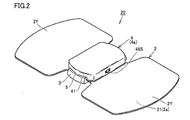
- FIG. 2 is a perspective view showing an example of the configuration of the electrotherapy device 20.
- FIG. 3 is a perspective view showing a state in which the main body 4 provided in the electrotherapy device 20 is separated from the holder 3 and the pad 2.
- the electrotherapy device 20 is a so-called cordless type low frequency therapy device, and includes a pad 2, a holder 3, and a main body 4.
- the pad 2 has a sheet-like shape and is attached to the user's body.
- a conductive layer 2 a is provided on the surface (lower surface) of the body side 21 facing the body among the outer surfaces of the pad 2.
- the pad 2 is attached on the skin of the user using a conductive gel or the like, and a low frequency pulse current is supplied to the user through the conductive layer 2a.
- pad 2 has attachment portion 2X and treatment portion 2Y.
- the mounting portion 2X is held by the holder 3.
- the mounting portion 2X is provided with a window portion 23 and a through hole 2H.
- the positioning projection 312 of the holder 3 is disposed inside the window portion 23.
- the interlock pin 33 of the holder 3 is inserted into the through hole 2H.
- the treatment portion 2Y is provided on the left and right sides of the attachment portion 2X, and the conductive layer 2a is exposed on the body side 21 of the treatment portion 2Y.
- the conductive layer 2 a is also exposed on the surface of the mounting portion 2 ⁇ / b> X facing the main body portion 4, and the exposed portion constitutes the pad side electrode portion 22.
- the pad-side electrode portion 22 is formed for electrical connection with the main-body-side electrode portion 43, and the conductive layer 2a corresponding to one electrode portion (for example, positive electrode) is exposed at one end of the attachment portion 2X.
- the conductive layer 2a corresponding to the other electrode portion (for example, the negative electrode) is exposed.
- the holder 3 includes a pad holding portion 31 having a plate-like shape, and a pair of wall portions 32 rising from both ends of the pad holding portion 31.
- the mounting portion 2 ⁇ / b> X of the pad 2 is disposed on the upper surface 311 of the pad holding portion 31.
- a double-sided adhesive tape, a glue, an adhesive agent, etc. are arrange
- the pad holding portion 31 is provided with a positioning protrusion 312.
- the pad 2 is positioned with respect to the holder 3 by aligning the inner peripheral edge of the window 23 provided in the pad 2 with the positioning protrusion 312.
- An interlock pin 33 is also provided at the center of the pad holder 31. When attaching the pad 2 to the holder 3, the interlock pin 33 is inserted into the through hole 2H.
- the pad 2 is a consumable item, the pad 2 is removable from the main body 4 at the time of replacement. In the present embodiment, both are integrated by holding the pad 2 by the holder 3, and the main body 4 is attached to and detached from the pad 2 and the holder 3. Although the pad 2 is replaced with the holder 3, it is not impossible to reuse the holder 3 as needed.
- main body 4 includes a casing 4 a having a substantially rectangular parallelepiped shape as an exterior body.
- An induction engaging portion 5 (FIG. 2) is formed between the housing 4 a and the holder 3, and the main body 4 (the housing 4 a) is detachably attached to the holder 3.
- the guiding engagement portion 5 is composed of a protrusion 51 (FIG. 3) formed on the side surface 41 of the housing 4 a and a groove 52 (FIG. 3) formed on the wall portion 32 of the holder 3.
- groove 52 includes a longitudinal groove 521 and a lateral groove 522.
- the longitudinal groove 521 is formed in the vertical direction, and the upper side is open.
- the lateral groove 522 is formed in the lateral direction, and both ends are open.
- the main body 4 supplies a low frequency pulse current to the conductive layer 2 a of the pad 2 in a state of being attached to the holder 3.
- the main body 4 includes a pair of main body side electrode portions 43, a substrate (not shown), an electric circuit (not shown), and an interlock mechanism (not shown).
- the electrical circuit includes various control devices and is mounted on the surface of the substrate.
- the control device includes a processor for executing various processes, a memory for storing programs and data, a communication interface for wirelessly communicating various data with the terminal device 10, boosting of the power supply voltage, and low frequency pulse current Waveform generation / output circuit for generating and outputting current, and the like as a vibrator as a vibration source.
- the vibrator is configured to have a vibration motor and its drive circuit, and vibrates the housing 4a by its driving. Although the vibrator is configured to apply a constant vibration to the housing 4a, the magnitude of the vibration may be appropriately adjusted in accordance with the amount of energization of the vibrator. In addition, the vibrator may be capable of adjusting the timing (vibration pattern) of the vibration as appropriate.
- the vibration source may not be a vibrator.
- the substrate, the electric circuit, and the interlock mechanism are provided inside the main body 4 (the housing 4a).
- a power supply (not shown) such as a battery is also provided inside the main body 4 (the housing 4a).
- a switch 48S (FIG. 2), a display unit (not shown) such as an LED (light emitting diode), a button (not shown) and the like are provided outside the housing 4a.
- the tip end of the main body side electrode portion 43 abuts on the pad side electrode portion 22.
- the main body side electrode portion 43 and the pad side electrode portion 22 are electrically connected, and the electric circuit can supply the low frequency pulse current to the pad side electrode portion 22.
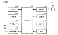
- FIG. 4 is a block diagram showing an example of the hardware configuration of the terminal device 10.
- the terminal device 10 includes, as main components, a processor 152, a memory 154, an input device 156, a display 158, a wireless communication unit 160, and a memory interface (I / F) 164.
- a communication interface (I / F) 166, a speaker 168, and a microphone 170 are included.
- the processor 152 is typically an arithmetic processing unit such as a central processing unit (CPU) or a multi processing unit (MPU).
- the processor 152 functions as a control unit that controls the operation of each unit of the terminal device 10 by reading and executing the program stored in the memory 154.
- the processor 152 implements each of the processes (steps) of the terminal device 10 described later by executing the program.
- the memory 154 is realized by a random access memory (RAM), a read-only memory (ROM), a flash memory, or the like.
- the memory 154 stores a program executed by the processor 152, data used by the processor 152, and the like.
- the input device 156 receives an operation input to the terminal device 10.
- the input device 156 is realized by a touch panel.
- the touch panel is provided on the display 158 having a function as a display unit, and is, for example, a capacitive type.
- the touch panel detects a touch operation on the touch panel by an external object every predetermined time, and inputs touch coordinates to the processor 152.
- the input device 156 may include a button or the like.
- the wireless communication unit 160 is connected to the mobile communication network via the communication antenna 162 to transmit and receive signals for wireless communication. Thereby, the terminal device 10 can communicate with another communication device via a mobile communication network such as LTE (Long Term Evolution), for example.
- LTE Long Term Evolution
- the memory interface 164 reads data from the external storage medium 165.
- the processor 152 reads the data stored in the storage medium 165 via the memory interface 164 and stores the data in the memory 154.
- the processor 152 reads data from the memory 154 and stores the data in the external storage medium 165 via the memory interface 164.
- the storage medium 165 is a non-volatile memory such as a CD (Compact Disc), a DVD (Digital Versatile Disk), a BD (Blu-ray (registered trademark) Disc), a USB (Universal Serial Bus) memory, and an SD (Secure Digital) memory card. Includes media for storing programs.
- a CD Compact Disc
- DVD Digital Versatile Disk
- BD Blu-ray (registered trademark) Disc
- USB Universal Serial Bus
- SD Secure Digital
- the communication interface (I / F) 166 is a communication interface for exchanging various data between the terminal device 10 and the electrotherapy device 20, and is realized by an adapter, a connector, or the like.
- a communication method for example, a wireless communication method using BLE (Bluetooth (registered trademark) low energy), a wireless LAN or the like is adopted.
- the speaker 168 converts the audio signal supplied from the processor 152 into audio and outputs the audio to the outside of the terminal device 10.
- the microphone 170 receives an audio input to the terminal device 10 and provides an audio signal corresponding to the audio input to the processor 152.
- FIGS. 5 to 8 An operation outline of the treatment system 1000 will be described with reference to FIGS. 5 to 8.
- the screens shown in FIG. 5 to FIG. 8 are screens displayed on the display 158 when the application for electric therapy installed on the terminal device 10 (hereinafter, also simply referred to as a “treatment application”) is activated. It is.
- the display 158 displays various image information.
- the image information includes symbols, characters, figures, and their combined images.
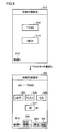
- FIG. 5 is a view showing an example of a setting screen of treatment contents.
- the terminal device 10 has completed pairing with the electrotherapy device 20 and has established a wireless communication connection with the electrotherapy device 20. Further, it is assumed that the user is sticking the pads 2 of the three electrotherapy devices 20A, 20B and 20C to a desired treatment site.
- setting screen 510 displays a mode selection button 512 for selecting a transcutaneous electrical nerve stimulation (TENS) mode, and a mode selection button 514 for selecting a MCR (microcurrent) mode.
- a character string 516 in FIG. 5 is a character string image indicating that it is a setting screen of the treatment content of the device X.
- the electrotherapy devices 20A, 20B, and 20C are associated with the devices X, Y, and Z (see FIG. 6 described later) on the treatment application screen.
- the user does not know that the electrotherapy devices 20A, 20B, and 20C are associated with the devices X, Y, and Z on the treatment application screen. Therefore, the user can not grasp which treatment site the device X corresponds to the electrotherapy device 20 corresponding to the pad 2 attached.
- the terminal device 10 when the terminal device 10 receives the selection operation (tap operation) of the character string 516, the terminal device 10 instructs the electrotherapy device 20A associated with the device X to vibrate the housing 4a with the vibrator. Thereby, since the housing 4a of the electrotherapy device 20A vibrates, the user can grasp to which treatment site the pad 2 of the electrotherapy device 20A associated with the device X is attached. When the treatment site is the waist, the user may set the treatment content for the waist as the treatment content of the device X.
- the TENS mode is a mode in which a sensory nerve is electrically stimulated to suppress or reduce pain.
- the MCR mode is a mode in which a muscle is stimulated to repair cells by supplying a weak current (microcurrent) to the body.
- the weak current is a current that does not cause muscle contraction, for example, 50 ⁇ A to 500 ⁇ A.
- the user selects the TENS mode, and the terminal device 10 displays the setting screen 520 when the selection of the mode selection button 512 is received.
- the setting screen 520 is a course selection screen in the TENS mode.
- the setting screen 520 includes a character string 526 indicating that the setting screen is the TENS mode, and a course selection button 523 for selecting the courses “male”, “tap”, and “momu”, respectively. 524 and 525 are displayed.
- a setting button 527 for setting a treatment time is displayed.
- the treatment content set to the mode "TENS”, the course "tap”, and the treatment time "10 minutes” is also referred to as a treatment content Ta.
- the back button 528 is selected, the setting screen 510 is displayed.
- the treatment contents are set for the other devices Y and Z.
- a pop-up menu for selecting the device to be set is displayed, and the character string "Device Y" (or Select the column "Device Z").
- a setting screen (a screen similar to the setting screen 510) of the treatment contents of the device Y is displayed.
- the treatment content of the device Y is set to the treatment content Tb (mode “TENS”, the course “m”, the treatment time “5 minutes”)
- the treatment content of the device Z is the treatment content Tc (mode “mode”
- Tb the treatment content
- Tc the treatment content
- “TENS”, course “male”, treatment time “30 minutes” are set.
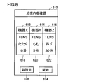
- FIG. 6 is a view showing an example of a confirmation screen of treatment contents.
- the confirmation screen 610 includes an object 612 including the character string "device X”, an object 614 including the character string “device Y”, an object 616 including the character string “device Z”, and treatment contents
- an object 620 including the treatment content Tb an object 622 including the treatment content Tc
- a start button 624 an object 626
- the “object” is various types of image information for presenting some information to the user in order to receive the user's operation, or for performing a function combining the two.
- the devices X to Z indicate that the treatment contents Ta to Tc are associated with one another. Thereby, the user can confirm the treatment content corresponding to the devices X to Z. Further, when the terminal device 10 receives a tap operation on the object 612, the terminal device 10 instructs the electrotherapy device 20A associated with the device X to vibrate the housing 4a. Similarly, when the terminal device 10 receives a tap operation on the object 614, the terminal device 10 vibrates the housing 4a of the electrotherapy device 20B associated with the device Y, and receives a tap operation on the object 616. , Vibrate the housing 4a of the electrotherapy device 20C associated with the device Z. Thereby, the user can reconfirm whether or not the desired treatment content is set at each treatment site.
- the terminal device 10 When the terminal device 10 receives the selection of the reset button 626, the terminal device 10 displays the setting screen 510.
- the terminal device 10 instructs the electrotherapy devices 20A to 20C associated with the devices X to Z to start the treatment.
- the start button By providing the start button for each of the devices X to Z, an instruction to start treatment may be made possible for each of the electrotherapy devices 20.
- the user can also exchange the treatment content associated with one device with the treatment content associated with another device.
- FIG. 7 is a diagram for explaining a method of exchanging treatment contents.
- the user wants to exchange the treatment content Tb associated with the device Y with the treatment content Tc associated with the device Z.
- object 620 and object 622 are exchanged. That is, the treatment content of the device Y and the treatment content of the device Z are exchanged.
- the treatment content before replacement of the device Y is set to the treatment content Tb
- the treatment content after replacement of the device Y is the treatment content Tc ( That is, the treatment content before replacement of the device Z is set.
- the treatment content after the replacement of the device Z is set to the treatment content before the replacement of the device Y (that is, the treatment content Tb).
- the exchange system of the treatment content is not restricted above, You may use another user interface. For example, the exchange button for exchanging the treatment content of each device may be displayed on the screen, and the treatment content of each device may be exchanged by selecting the exchange button.
- the terminal device 10 exchanges the treatment content corresponding to the device X (ie, the electrotherapy device 20A) and the treatment content corresponding to the device Y (ie, the electrotherapy device 20B) according to the user's instruction. be able to.
- FIG. 8 is a diagram showing an example of a screen during treatment.
- the terminal device 10 receives the selection of the start button 624 on the confirmation screen 610 shown in FIG. 6, the terminal device 10 displays the in-treatment screen 710 shown in FIG.
- the object 718 is obtained by adding a button 730 for raising the stimulation level and a button 732 for lowering the stimulation level to the object 618 of the confirmation screen 610 (see FIG. 6).
- the object 720 is obtained by adding the button 730 and the button 732 to the object 620
- the object 722 is obtained by adding the button 730 and the button 732 to the object 622.
- the user can select the buttons 732 732 to change the stimulation level.
- the terminal device 10 When receiving the selection of the stop button 740, the terminal device 10 instructs the electrotherapy devices 20A to 20C associated with all the devices X to Z to stop the treatment.
- the terminal device 10 instructs the electrotherapy devices 20A to 20C associated with all the devices X to Z to stop the treatment.
- an instruction to stop treatment may be made possible for each of the electrotherapy devices 20.
- the in-treatment screen 710 may include an end button for giving an instruction to end the treatment.
- the terminal device 10 can instruct the electrotherapy devices 20A to 20C to vibrate the housing 4a by receiving a tap operation on the objects 612 to 616 even during treatment. This is particularly useful when the MCR mode is selected. Specifically, in the MCR mode, a weak current that does not cause muscle contraction flows, so the electrical stimulation intensity felt by the user is very small, and it is difficult for the user to feel that treatment is being performed in the MCR mode. Therefore, the user can grasp that the treatment is performed in the MCR mode by performing the tap operation on the objects 612 to 616 and vibrating the housing 4a of the electrotherapy devices 20A to 20C.
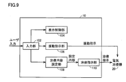
- FIG. 9 is a block diagram showing an example of a functional configuration of the terminal device 10.
- terminal device 10 mainly includes an input unit 102, a display control unit 104, a vibration instruction unit 106, a treatment content setting unit 108, and a treatment instruction unit 110.
- Each function of the terminal device 10 is realized, for example, by the processor 152 of each terminal device 10 executing a program stored in the memory 154. Note that some or all of these functions may be configured to be realized by hardware.
- the input unit 102 receives an instruction input from the user via the input device 156.
- the input unit 102 outputs instruction input information from the user to the display control unit 104, the vibration instructing unit 106, and the treatment content setting unit 108.
- the display control unit 104 causes the display 158 to display various information. Specifically, the display control unit 104 causes the display 158 to display the setting screens 510 and 520, the confirmation screen 610, the in-treatment screen 710, and the like described above. Specifically, the display control unit 104 causes the display 158 of the terminal device 10 to display image information (for example, a character string 516, objects 612, 614, 616, etc.) associated with each of the electrotherapy devices 20.
- image information for example, a character string 516, objects 612, 614, 616, etc.
- the vibration instruction unit 106 instructs the electrotherapy device 20 associated with the image information selected by the user to vibrate the housing 4 a. Specifically, the vibration instructing unit 106 transmits, to the electrotherapy device 20, control information for executing driving of the vibrator of the electrotherapy device 20. In one aspect, when the electrotherapy device 20 is performing a treatment according to the corresponding treatment content, the vibration instruction unit 106 selects image information (for example, objects 612 to 616) associated with the electrotherapy device 20. And instructs the electrotherapy device 20 to vibrate the housing 4a.
- image information for example, objects 612 to 616
- the treatment content setting unit 108 sets the treatment content to be performed by each of the electrotherapy devices 20 according to the instruction of the user who has received the notification of the vibration of the housing 4 a.
- Treatment content includes treatment mode, treatment course, and treatment time.
- the treatment content setting unit 108 exchanges the treatment content of each of the electrotherapy devices 20 according to the instruction of the user. For example, the treatment content setting unit 108 exchanges the treatment content corresponding to the electrotherapy device 20B with the treatment content corresponding to the electrotherapy device 20C.
- the treatment content setting unit 108 includes image information (for example, the object 614) associated with a predetermined one of the electric therapy devices 20A to 20C (for example, the electric therapy device 20B)
- the predetermined treatment content is set as the treatment content to be performed by the predetermined electrotherapy device.
- the treatment content Tc mode “TENS”, course “male”, treatment time “30 minutes”
- the treatment content Tc mode “TENS”, course “male”, treatment time “30 minutes” is the treatment content of the electrotherapy device 20A. It is set.
- the treatment instructing unit 110 instructs each of the plurality of electrotherapy devices 20 to treat the user according to the treatment content corresponding to the electrotherapy device 20.
- the treatment instruction unit 110 transmits control information for executing each treatment content to each of the electrotherapy devices 20. Further, the treatment instructing unit 110 transmits various control information to each of the electrotherapy devices 20 according to various instructions from the user (for example, an instruction to change the stimulation level, an instruction to stop the treatment, etc.).
- the treatment instructing unit 110 instructs the first and second electrotherapy devices to treat the user according to the treatment content after replacement.
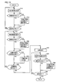
- FIG. 10 is a flowchart illustrating an example of the processing procedure of the terminal device 10. Each step shown in FIG. 10 is mainly realized by the processor 152 of the terminal device 10 executing a program (treatment application) stored in the memory 154. At the start of the flowchart, the terminal device 10 is assumed to have completed pairing with the electrotherapy device 20 and established a wireless communication connection with the electrotherapy device 20. Further, it is assumed that the user is sticking the pads 2 of the three electrotherapy devices 20A, 20B and 20C to a desired treatment site.
- a program treatment application
- the terminal device 10 displays a setting screen (for example, setting screens 510 and 520) of treatment contents on the display 158 (step S10).
- the terminal device 10 determines whether a vibration instruction (for example, a tap operation of the character string 516) to the electrotherapy device 20 has been received through the input device 156 (step S12).
- step S16 If the vibration instruction has not been received (NO in step S12), the process of step S16 is performed. If the vibration instruction has been received (YES in step S12), the terminal device 10 instructs the target electrotherapy device 20 associated with the character string 516 to vibrate the housing 4a (step S14). Subsequently, the terminal device 10 determines whether an instruction for confirmation of the treatment content (for example, a tap operation of the confirmation button 529) is received through the input device 156 (step S16).
- an instruction for confirmation of the treatment content for example, a tap operation of the confirmation button 529
- step S16 If the confirmation instruction has not been received (NO in step S16), the terminal device 10 returns to the process of step S10.
- the terminal device 10 displays a confirmation screen (for example, a confirmation screen 610) of the treatment content on the display 158 (step S18).
- the terminal device 10 determines whether a vibration instruction (for example, a tap operation on any of the objects 612 to 616) to the electrotherapy device 20 has been received via the input device 156 (step S20).
- step S24 If the vibration instruction has not been received (NO in step S20), the process of step S24 is executed. If the vibration instruction has been received (YES in step S20), the terminal device 10 instructs the target electric therapeutic device 20 associated with the selected object to vibrate the housing 4a (step S22). . Subsequently, the terminal device 10 determines whether an instruction to exchange treatment content (for example, an operation to exchange the object 614 and the object 616) is received through the input device 156 (step S24).
- an instruction to exchange treatment content for example, an operation to exchange the object 614 and the object 616
- step S24 If the exchange instruction has not been received (NO in step S24), the terminal device 10 executes the process of step S28.
- the terminal device 10 exchanges the treatment content (step S26), and whether or not the treatment start instruction (for example, the tap operation to the start button 624) is received It judges (step S28).
- step S28 If the treatment start instruction has not been received (NO in step S28), the terminal device 10 returns to the process of step S18.
- a treatment start instruction is received (YES in step S28)
- the terminal device 10 instructs each of the electrotherapy devices 20 to treat the user according to the corresponding treatment content (step S30), and the treatment is underway
- a screen for example, the in-treatment screen 710 is displayed on the display 158 (step S32).
- the terminal device 10 determines whether or not a vibration instruction to the electrotherapy device 20 (for example, a tap operation on any of the objects 612 to 616) has been received via the input device 156 (step S34). .
- step S34 If the vibration instruction has not been received (NO in step S34), the process of step S38 is performed. If the vibration instruction has been received (YES in step S34), the terminal device 10 instructs the electrotherapy device 20 of the object associated with the selected object to vibrate the housing 4a (step S36). .
- the terminal device 10 determines whether the treatment has ended via the input device 156 (step S38). For example, the terminal device 10 determines that the treatment has ended when the treatment time has elapsed or when a treatment stop instruction has been received from the user. If the treatment has not ended (NO in step S38), the terminal device 10 returns to the process of step S32. When the treatment ends (YES in step S38), the terminal device 10 ends the process.
- each electrotherapy device 20 can be vibrated by the tap operation on the screen of the terminal device 10 . Therefore, the user can easily set the treatment content to be performed for each treatment site, and can prevent the erroneous setting of the treatment content. In addition, it is not necessary to be aware of which electrotherapy device 20 is applied to which treatment site before attaching the pads of the plurality of electrotherapy devices 20 to the treatment site.
- each electrotherapy device 20 can be vibrated by the tap operation on the setting screen of the treatment content, the confirmation screen of the treatment content, and the in-treatment screen. Therefore, the user can always check whether the desired treatment content is set for the treatment site.
- a program that causes a computer to function to execute control as described in the above-described flowchart.
- a program is recorded on a non-temporary computer readable recording medium such as a flexible disk attached to a computer, a CD (Compact Disk Read Only Memory), a secondary storage device, a main storage device, and a memory card. It can also be provided as a program product.
- the program can be provided by being recorded in a recording medium such as a hard disk built in the computer.
- the program can be provided by downloading via a network.
- the program may call a required module among program modules provided as a part of an operating system (OS) of a computer in a predetermined arrangement at a predetermined timing to execute processing.
- OS operating system
- the program itself does not include the above module, and the processing is executed in cooperation with the OS.
- a program that does not include such a module may also be included in the program according to the present embodiment.
- the program according to the present embodiment may be provided by being incorporated into a part of another program. Also in this case, the program itself does not include a module included in the other program, and the process is executed in cooperation with the other program. Programs incorporated into such other programs may also be included in the program according to the present embodiment.
- the configuration exemplified as the above-described embodiment is an example of the configuration of the present invention, and can be combined with another known technique, and part of the configuration is omitted without departing from the scope of the present invention, etc. It is also possible to change and configure. Moreover, in the embodiment described above, the processing and configuration described in the other embodiments may be appropriately adopted and implemented.
Landscapes
- Health & Medical Sciences (AREA)
- Life Sciences & Earth Sciences (AREA)
- Animal Behavior & Ethology (AREA)
- General Health & Medical Sciences (AREA)
- Biomedical Technology (AREA)
- Nuclear Medicine, Radiotherapy & Molecular Imaging (AREA)
- Radiology & Medical Imaging (AREA)
- Veterinary Medicine (AREA)
- Public Health (AREA)
- Engineering & Computer Science (AREA)
- Heart & Thoracic Surgery (AREA)
- Biophysics (AREA)
- Neurology (AREA)
- Electrotherapy Devices (AREA)
- User Interface Of Digital Computer (AREA)
- Percussion Or Vibration Massage (AREA)
Priority Applications (3)
| Application Number | Priority Date | Filing Date | Title |
|---|---|---|---|
| DE112018003098.9T DE112018003098B4 (de) | 2017-07-27 | 2018-06-12 | Endvorrichtung, Steuerverfahren, Programm und Behandlungssystem |
| CN201880044448.XA CN110831657B (zh) | 2017-07-27 | 2018-06-12 | 终端装置、控制方法、计算机可读取记录介质以及治疗系统 |
| US16/734,575 US11305117B2 (en) | 2017-07-27 | 2020-01-06 | Terminal device, control method, program, and treatment system |
Applications Claiming Priority (2)
| Application Number | Priority Date | Filing Date | Title |
|---|---|---|---|
| JP2017145456A JP6907781B2 (ja) | 2017-07-27 | 2017-07-27 | 端末装置、制御方法、プログラム、および治療システム |
| JP2017-145456 | 2017-07-27 |
Related Child Applications (1)
| Application Number | Title | Priority Date | Filing Date |
|---|---|---|---|
| US16/734,575 Continuation US11305117B2 (en) | 2017-07-27 | 2020-01-06 | Terminal device, control method, program, and treatment system |
Publications (1)
| Publication Number | Publication Date |
|---|---|
| WO2019021659A1 true WO2019021659A1 (ja) | 2019-01-31 |
Family
ID=65039598
Family Applications (1)
| Application Number | Title | Priority Date | Filing Date |
|---|---|---|---|
| PCT/JP2018/022369 Ceased WO2019021659A1 (ja) | 2017-07-27 | 2018-06-12 | 端末装置、制御方法、プログラム、および治療システム |
Country Status (5)
| Country | Link |
|---|---|
| US (1) | US11305117B2 (enExample) |
| JP (1) | JP6907781B2 (enExample) |
| CN (1) | CN110831657B (enExample) |
| DE (1) | DE112018003098B4 (enExample) |
| WO (1) | WO2019021659A1 (enExample) |
Families Citing this family (8)
| Publication number | Priority date | Publication date | Assignee | Title |
|---|---|---|---|---|
| US9782585B2 (en) | 2013-08-27 | 2017-10-10 | Halo Neuro, Inc. | Method and system for providing electrical stimulation to a user |
| US9630005B2 (en) | 2013-08-27 | 2017-04-25 | Halo Neuro, Inc. | Method and system for providing electrical stimulation to a user |
| US10315033B2 (en) | 2016-02-08 | 2019-06-11 | Halo Neuro, Inc. | Method and system for improving provision of electrical stimulation |
| US10507324B2 (en) | 2017-11-17 | 2019-12-17 | Halo Neuro, Inc. | System and method for individualizing modulation |
| EP3603737B1 (en) | 2018-07-31 | 2020-08-26 | Flow Neuroscience AB | Positioning of electrodes for transcranial brain stimulation |
| US20200215321A1 (en) * | 2019-01-07 | 2020-07-09 | Halo Neuro, Inc. | System and method for delivering electrical stimulation |
| JP7352800B2 (ja) * | 2020-03-27 | 2023-09-29 | パナソニックIpマネジメント株式会社 | 生体情報取得方法、プログラム、及び生体情報取得システム |
| CN113648204B (zh) * | 2021-08-18 | 2025-08-05 | 云南力衡医疗技术有限公司 | 一种用于治疗仪输出处方检查验证的方法和系统 |
Citations (3)
| Publication number | Priority date | Publication date | Assignee | Title |
|---|---|---|---|---|
| JPH0454974A (ja) * | 1990-06-26 | 1992-02-21 | Matsushita Electric Works Ltd | 無線式低周波治療器 |
| JP3153006U (ja) * | 2009-06-10 | 2009-08-20 | 新象興業有限公司 | マッサージ器 |
| JP2014526282A (ja) * | 2011-09-01 | 2014-10-06 | ゾール メディカル コーポレイション | 着用可能モニタリングおよび治療装置 |
Family Cites Families (6)
| Publication number | Priority date | Publication date | Assignee | Title |
|---|---|---|---|---|
| JP2005252449A (ja) * | 2004-03-02 | 2005-09-15 | Hitachi Software Eng Co Ltd | 携帯通信端末及び低周波パルス電圧制御方法 |
| US9289613B2 (en) * | 2008-10-31 | 2016-03-22 | Medtronic, Inc. | Interdevice impedance |
| JP5920910B2 (ja) * | 2011-10-31 | 2016-05-18 | オージー技研株式会社 | 電気刺激装置及び電気刺激装置システム |
| CN104056350A (zh) * | 2014-06-12 | 2014-09-24 | 深圳市宏强兴电子有限公司 | 低频治疗仪移动控制系统 |
| US10463854B2 (en) * | 2015-02-24 | 2019-11-05 | Elira, Inc. | Systems and methods for managing symptoms associated with dysmenorrhea using an electro-dermal patch |
| US10376145B2 (en) * | 2015-02-24 | 2019-08-13 | Elira, Inc. | Systems and methods for enabling a patient to achieve a weight loss objective using an electrical dermal patch |
-
2017
- 2017-07-27 JP JP2017145456A patent/JP6907781B2/ja active Active
-
2018
- 2018-06-12 DE DE112018003098.9T patent/DE112018003098B4/de active Active
- 2018-06-12 CN CN201880044448.XA patent/CN110831657B/zh active Active
- 2018-06-12 WO PCT/JP2018/022369 patent/WO2019021659A1/ja not_active Ceased
-
2020
- 2020-01-06 US US16/734,575 patent/US11305117B2/en active Active
Patent Citations (3)
| Publication number | Priority date | Publication date | Assignee | Title |
|---|---|---|---|---|
| JPH0454974A (ja) * | 1990-06-26 | 1992-02-21 | Matsushita Electric Works Ltd | 無線式低周波治療器 |
| JP3153006U (ja) * | 2009-06-10 | 2009-08-20 | 新象興業有限公司 | マッサージ器 |
| JP2014526282A (ja) * | 2011-09-01 | 2014-10-06 | ゾール メディカル コーポレイション | 着用可能モニタリングおよび治療装置 |
Also Published As
| Publication number | Publication date |
|---|---|
| CN110831657B (zh) | 2023-07-18 |
| DE112018003098T5 (de) | 2020-03-26 |
| DE112018003098B4 (de) | 2024-03-14 |
| JP2019024720A (ja) | 2019-02-21 |
| US11305117B2 (en) | 2022-04-19 |
| CN110831657A (zh) | 2020-02-21 |
| US20200139117A1 (en) | 2020-05-07 |
| JP6907781B2 (ja) | 2021-07-21 |
Similar Documents
| Publication | Publication Date | Title |
|---|---|---|
| JP6907781B2 (ja) | 端末装置、制御方法、プログラム、および治療システム | |
| US10960205B2 (en) | Electric treatment device and treatment system | |
| JP2017526496A (ja) | 経皮的電気神経刺激(tens)装置 | |
| US11324951B2 (en) | Electrical treatment device, control method, and treatment system | |
| JP6733514B2 (ja) | 電気治療器、および治療システム | |
| US11826567B2 (en) | Electrical treatment device, control method, and treatment system | |
| JP2018108276A (ja) | 電気治療器、システムおよびプログラム | |
| CN112584893A (zh) | 终端装置、电疗仪及治疗系统 | |
| JP2019201990A (ja) | 電気治療器、および治療システム | |
| JP6926697B2 (ja) | 端末装置、治療システムおよびプログラム | |
| JP6907729B2 (ja) | 端末装置、治療システムおよびプログラム | |
| JP2019187505A (ja) | 電気治療器、および治療システム | |
| TW201822834A (zh) | 經皮電神經刺激設備 |
Legal Events
| Date | Code | Title | Description |
|---|---|---|---|
| 121 | Ep: the epo has been informed by wipo that ep was designated in this application |
Ref document number: 18837498 Country of ref document: EP Kind code of ref document: A1 |
|
| 122 | Ep: pct application non-entry in european phase |
Ref document number: 18837498 Country of ref document: EP Kind code of ref document: A1 |