WO2019017182A1 - Sliding member and sliding bearing - Google Patents
Sliding member and sliding bearing Download PDFInfo
- Publication number
- WO2019017182A1 WO2019017182A1 PCT/JP2018/024804 JP2018024804W WO2019017182A1 WO 2019017182 A1 WO2019017182 A1 WO 2019017182A1 JP 2018024804 W JP2018024804 W JP 2018024804W WO 2019017182 A1 WO2019017182 A1 WO 2019017182A1
- Authority
- WO
- WIPO (PCT)
- Prior art keywords
- metal element
- overlay
- intermetallic compound
- sliding member
- lining
- Prior art date
Links
Images


Classifications
-
- F—MECHANICAL ENGINEERING; LIGHTING; HEATING; WEAPONS; BLASTING
- F16—ENGINEERING ELEMENTS AND UNITS; GENERAL MEASURES FOR PRODUCING AND MAINTAINING EFFECTIVE FUNCTIONING OF MACHINES OR INSTALLATIONS; THERMAL INSULATION IN GENERAL
- F16C—SHAFTS; FLEXIBLE SHAFTS; ELEMENTS OR CRANKSHAFT MECHANISMS; ROTARY BODIES OTHER THAN GEARING ELEMENTS; BEARINGS
- F16C33/00—Parts of bearings; Special methods for making bearings or parts thereof
- F16C33/02—Parts of sliding-contact bearings
- F16C33/04—Brasses; Bushes; Linings
- F16C33/06—Sliding surface mainly made of metal
- F16C33/12—Structural composition; Use of special materials or surface treatments, e.g. for rust-proofing
- F16C33/122—Multilayer structures of sleeves, washers or liners
-
- C—CHEMISTRY; METALLURGY
- C22—METALLURGY; FERROUS OR NON-FERROUS ALLOYS; TREATMENT OF ALLOYS OR NON-FERROUS METALS
- C22C—ALLOYS
- C22C12/00—Alloys based on antimony or bismuth
-
- C—CHEMISTRY; METALLURGY
- C22—METALLURGY; FERROUS OR NON-FERROUS ALLOYS; TREATMENT OF ALLOYS OR NON-FERROUS METALS
- C22C—ALLOYS
- C22C13/00—Alloys based on tin
-
- C—CHEMISTRY; METALLURGY
- C25—ELECTROLYTIC OR ELECTROPHORETIC PROCESSES; APPARATUS THEREFOR
- C25D—PROCESSES FOR THE ELECTROLYTIC OR ELECTROPHORETIC PRODUCTION OF COATINGS; ELECTROFORMING; APPARATUS THEREFOR
- C25D3/00—Electroplating: Baths therefor
- C25D3/02—Electroplating: Baths therefor from solutions
- C25D3/56—Electroplating: Baths therefor from solutions of alloys
-
- C—CHEMISTRY; METALLURGY
- C25—ELECTROLYTIC OR ELECTROPHORETIC PROCESSES; APPARATUS THEREFOR
- C25D—PROCESSES FOR THE ELECTROLYTIC OR ELECTROPHORETIC PRODUCTION OF COATINGS; ELECTROFORMING; APPARATUS THEREFOR
- C25D7/00—Electroplating characterised by the article coated
- C25D7/10—Bearings
-
- F—MECHANICAL ENGINEERING; LIGHTING; HEATING; WEAPONS; BLASTING
- F16—ENGINEERING ELEMENTS AND UNITS; GENERAL MEASURES FOR PRODUCING AND MAINTAINING EFFECTIVE FUNCTIONING OF MACHINES OR INSTALLATIONS; THERMAL INSULATION IN GENERAL
- F16C—SHAFTS; FLEXIBLE SHAFTS; ELEMENTS OR CRANKSHAFT MECHANISMS; ROTARY BODIES OTHER THAN GEARING ELEMENTS; BEARINGS
- F16C33/00—Parts of bearings; Special methods for making bearings or parts thereof
- F16C33/02—Parts of sliding-contact bearings
- F16C33/04—Brasses; Bushes; Linings
- F16C33/06—Sliding surface mainly made of metal
- F16C33/12—Structural composition; Use of special materials or surface treatments, e.g. for rust-proofing
- F16C33/121—Use of special materials
-
- F—MECHANICAL ENGINEERING; LIGHTING; HEATING; WEAPONS; BLASTING
- F16—ENGINEERING ELEMENTS AND UNITS; GENERAL MEASURES FOR PRODUCING AND MAINTAINING EFFECTIVE FUNCTIONING OF MACHINES OR INSTALLATIONS; THERMAL INSULATION IN GENERAL
- F16C—SHAFTS; FLEXIBLE SHAFTS; ELEMENTS OR CRANKSHAFT MECHANISMS; ROTARY BODIES OTHER THAN GEARING ELEMENTS; BEARINGS
- F16C2204/00—Metallic materials; Alloys
- F16C2204/10—Alloys based on copper
- F16C2204/12—Alloys based on copper with tin as the next major constituent
-
- F—MECHANICAL ENGINEERING; LIGHTING; HEATING; WEAPONS; BLASTING
- F16—ENGINEERING ELEMENTS AND UNITS; GENERAL MEASURES FOR PRODUCING AND MAINTAINING EFFECTIVE FUNCTIONING OF MACHINES OR INSTALLATIONS; THERMAL INSULATION IN GENERAL
- F16C—SHAFTS; FLEXIBLE SHAFTS; ELEMENTS OR CRANKSHAFT MECHANISMS; ROTARY BODIES OTHER THAN GEARING ELEMENTS; BEARINGS
- F16C2204/00—Metallic materials; Alloys
- F16C2204/10—Alloys based on copper
- F16C2204/18—Alloys based on copper with bismuth as the next major constituent
-
- F—MECHANICAL ENGINEERING; LIGHTING; HEATING; WEAPONS; BLASTING
- F16—ENGINEERING ELEMENTS AND UNITS; GENERAL MEASURES FOR PRODUCING AND MAINTAINING EFFECTIVE FUNCTIONING OF MACHINES OR INSTALLATIONS; THERMAL INSULATION IN GENERAL
- F16C—SHAFTS; FLEXIBLE SHAFTS; ELEMENTS OR CRANKSHAFT MECHANISMS; ROTARY BODIES OTHER THAN GEARING ELEMENTS; BEARINGS
- F16C2204/00—Metallic materials; Alloys
- F16C2204/30—Alloys based on one of tin, lead, antimony, bismuth, indium, e.g. materials for providing sliding surfaces
-
- F—MECHANICAL ENGINEERING; LIGHTING; HEATING; WEAPONS; BLASTING
- F16—ENGINEERING ELEMENTS AND UNITS; GENERAL MEASURES FOR PRODUCING AND MAINTAINING EFFECTIVE FUNCTIONING OF MACHINES OR INSTALLATIONS; THERMAL INSULATION IN GENERAL
- F16C—SHAFTS; FLEXIBLE SHAFTS; ELEMENTS OR CRANKSHAFT MECHANISMS; ROTARY BODIES OTHER THAN GEARING ELEMENTS; BEARINGS
- F16C33/00—Parts of bearings; Special methods for making bearings or parts thereof
- F16C33/02—Parts of sliding-contact bearings
- F16C33/04—Brasses; Bushes; Linings
- F16C33/06—Sliding surface mainly made of metal
- F16C33/14—Special methods of manufacture; Running-in
Definitions
- the present invention relates to a sliding member and a sliding bearing in which a mating material slides on a sliding surface.
- Patent Document 1 An overlay layer formed of a Bi alloy containing Cu as an essential element and containing at least one of Sn and In is known (see Patent Document 1).
- Patent Document 1 describes that fatigue resistance is improved by containing Cu, Sn, or In in a Bi alloy.
- a tin-based overlay in which Cu is added to Sn which is a soft metal is known (see Patent Document 2).
- Patent Document 1 the addition of Cu as a strengthening element to Sn improves the wear resistance and the fatigue resistance.
- the present invention has been made in view of the above problems, and an object of the present invention is to provide a technique capable of realizing improvement in the fatigue resistance of an overlay.
- the sliding member and the sliding bearing of the present invention are sliding members in which a cover layer is laminated on a base layer, and the cover layer is made of Sn as a first metal element, A second metal element which is harder than the metal element and forms an intermetallic compound with the first metal element, 0.010 mass% or more and 0.080 mass% or less of C, and unavoidable impurities It consists of
- the second metal element may be any element that is harder than Bi and forms an intermetallic compound with Bi, and may be, for example, Ag, Sb, Ni or the like.
- the second metal element may be 0.5 mass% or more and 5.0 mass% or less, desirably 1.0 mass% or more and 3.0 mass% or less.
- Bi as the first metal element constitutes the balance of the second metal element, C, and the unavoidable impurities.
- the sliding member and the sliding bearing of the present invention are sliding members in which a cover layer is laminated on a base layer, and the cover layer is made of Sn as a first metal element, And a second metal element which is harder than the metal element and forms an intermetallic compound with the first metal element, 0.015 wt% or more and 0.100 wt% or less of C, and an unavoidable impurity.
- the second metal element may be any element that is harder than Sn and forms an intermetallic compound with Sn, and may be, for example, Ag, Sb, or Ni.
- the second metal element may be 0.5 wt% or more and 10.0 wt% or less, and desirably 1.0 wt% or more and 5.0 wt% or less.
- Sn as the first metal element constitutes the balance of the second metal, C, and unavoidable impurities.
- FIG. 1 is a perspective view of a sliding member 1 according to an embodiment of the present invention.
- the sliding member 1 includes a back metal 10, a lining 11 and an overlay 12.
- the sliding member 1 is a metal member in the shape of a half in which a hollow cylinder is divided into two in the diameter direction, and the cross section thereof has a semicircular arc shape.
- the sliding bearing A is formed by combining the two sliding members 1 in a cylindrical shape.
- the slide bearing A bears a cylindrical counterpart shaft 2 (engine crankshaft) at a hollow portion formed inside.
- the outer diameter of the mating shaft 2 is formed slightly smaller than the inner diameter of the slide bearing A.
- Lubricating oil engine oil
- the sliding member 1 has a structure in which the back metal 10, the lining 11 and the overlay 12 are sequentially stacked in order of distance from the center of curvature. Therefore, the back metal 10 constitutes the outermost layer of the sliding member 1, and the overlay 12 constitutes the innermost layer of the sliding member 1.
- the back metal 10, the lining 11 and the overlay 12 each have a constant thickness in the circumferential direction.
- the thickness of the back metal 10 is 1.8 mm
- the thickness of the lining 11 is 0.2 mm
- the thickness of the overlay 12 is 10 ⁇ m.
- the double of the radius of the surface of the overlay 12 on the side of the center of curvature (the inner diameter of the sliding member 1) is 73 mm.
- the inner side means the center of curvature of the sliding member 1
- the outer side means the side opposite to the center of curvature of the sliding member 1.
- the inner surface of the overlay 12 constitutes the sliding surface of the countershaft 2.
- the back metal 10 is formed of steel containing 0.15 mass% of C, 0.06 mass% of Mn, and the balance of Fe.
- the back metal 10 should just be formed with the material which can support the load from the other axis
- the lining 11 is a layer laminated on the inner side of the back metal 10, and constitutes the base layer of the present invention.
- the lining 11 contains 10% by mass of Sn, 8% by mass of Bi, and the balance consists of Cu and unavoidable impurities.
- Unavoidable impurities of the lining 11 are Mg, Ti, B, Pb, Cr, etc., which are impurities mixed in refining or scrap.
- the content of unavoidable impurities in the lining 11 is 1.0 mass% or less in total.
- the lining 11 is not limited to the composition described above, and may be, for example, an Al alloy in which the total amount of one or more of Bi, Sn, In, and Ni and the unavoidable impurities is 25% by mass or less.
- the lining 11 may be a Cu alloy.
- the lining 11 may be a Cu alloy in which the total amount of one or more of Sn, Si, Zn, Mg, Cr, Zr, Ni, and V and unavoidable impurities is 25% by mass or less.
- the overlay 12 is a layer laminated on the inner surface of the lining 11 and constitutes the covering layer of the present invention.
- the covering layer is composed of Bi as a first metal element, Ni as a second metal element forming an intermetallic compound with the first metal element, C, and an unavoidable impurity.
- the content of Ni is 2.0% by mass
- the content of C is 0.03% by mass
- the total content of unavoidable impurities is 1.0% by mass or less.
- the rest is Bi.
- the fatigue damage area ratio was as good as 2.0%.
- an appropriate amount of C serves as a diffusion barrier and the intermetallic compound becomes coarse.
- Bi 3 Ni or the like is precipitated in the overlay 12 as an intermetallic compound, but C acts as a diffusion barrier, and coarsening of Bi 3 Ni or the like can be suppressed. This allows the interface between the soft Bi and the hard intermetallic compound to be kept at a small size. Therefore, even if a fatigue crack is generated at the interface between the soft Bi and the hard intermetallic compound, the possibility that the fatigue crack is greatly developed can be reduced, and the fatigue resistance can be improved.
- (1-2) Measurement method In addition, the fatigue damage area rate was measured in the following procedures. First, as shown in FIG. 2, a connecting rod R in which cylindrical through holes were formed at both ends in the length direction was prepared, and a test axis H (hatching) was supported by the through holes at one end. An overlay 12 (black) similar to that of the sliding member 1 was formed on the inner peripheral surface of the through hole of the connecting rod R bearing the test axis H. The test axis H was supported on both outer sides of the connecting rod R in the axial direction of the test axis H, and the test axis H was rotated so that the sliding speed was 6.6 m / sec. The sliding speed is the relative speed between the surface of the overlay 12 and the test axis H.
- the end of the connecting rod R opposite to the test axis H was connected to a moving body F reciprocating in the longitudinal direction of the connecting rod R, and the reciprocating load of the moving body F was 57 MPa. Further, engine oil at 120 ° C. was supplied between the connecting rod R and the test axis H.
- the fatigue test of the overlay 12 was performed by continuing the above-mentioned state for 50 hours. Then, after the fatigue test, the inner surface (sliding surface) of the overlay 12 is photographed from the position on the straight line orthogonal to the surface, and the photographed straight line is taken as the main optical axis, and the photographed image is An evaluation image was obtained. Then, the damaged portion of the surface of the overlay 12 shown in the evaluation image is observed by a vincula (magnifying glass) and identified, and the damaged part area, which is the area of the damaged portion, is shown in the evaluation image The percentage of the value divided by the area of the entire surface of 12 was measured as the fatigue damage area rate.
- the mass of the element constituting each layer of the sliding member 1 was measured by an ICP emission spectrometer (ICPS-8100 manufactured by Shimadzu Corporation).
- the carbon concentration in the overlay 12 was measured by a high frequency induction heating furnace combustion infrared absorption method (JIS G 1211 carbon content analysis method for steel).
- each layer was measured by the following procedure. First, the vertical cross section of the sliding member 1 in the axial direction was polished with a cross section polisher (IB-09010 CP, manufactured by Nippon Denshi K.K.). Then, the cross section of the sliding member 1 was photographed with an electron microscope (JSM-6610A manufactured by JEOL) at a magnification of 7,000 times to obtain image data of an observation image (reflected electron image). Then, the film thickness was measured by analyzing the observation image with an image analyzer (Lusex AP manufactured by Nireco).
- IB-09010 CP manufactured by Nippon Denshi K.K.
- (1-3) Manufacturing Method of Sliding Member First, a flat plate of low carbon steel having the same thickness as the backing metal 10 was prepared. Next, the powder of the material which comprises lining 11 is sprinkled on the plane board formed with low carbon steel. Specifically, Cu powder, Bi powder, and Sn powder were dispersed on a flat plate of low carbon steel so that the mass ratio of each component in the lining 11 described above was obtained. As long as the mass ratio of each component in the lining 11 can be satisfied, an alloy powder such as Cu—Bi, Cu—Sn may be dispersed on a flat plate of low carbon steel. The particle size of the powder was adjusted to 150 ⁇ m or less by a test sieve (JIS Z8801).
- the sintering temperature was controlled to 700 to 1000 ° C., and sintering was performed in an inert atmosphere. After sintering, it cooled.
- the lining 11 may not necessarily be formed by sintering, and may be formed by casting or the like.
- a Cu alloy layer is formed on a flat plate of low carbon steel.
- the Cu alloy layer contains soft Bi particles precipitated during cooling.
- the low carbon steel on which the Cu alloy layer was formed was pressed so as to be a shape obtained by equally dividing the hollow cylinder into two in the diameter direction. At this time, pressing was performed so that the outer diameter of the low carbon steel matched the outer diameter of the sliding member 1.
- the surface of the Cu alloy layer formed on the back metal 10 was cut.
- the cutting amount was controlled so that the thickness of the Cu alloy layer formed on the back metal 10 was the same as that of the lining 11.
- the lining 11 can be formed by the Cu alloy layer after cutting.
- the cutting process was performed by, for example, a lathe in which a cutting tool material formed of sintered diamond was set.
- the surface of the lining 11 after cutting forms an interface between the lining 11 and the overlay 12.
- an overlay 12 was formed by laminating Bi to a thickness of 10 ⁇ m by electroplating on the surface of the lining 11.
- the procedure of electroplating was as follows. First, the surface of the lining 11 was washed with water. Furthermore, by pickling the surface of the lining 11, unnecessary oxide was removed from the surface of the lining 11. Thereafter, the surface of the lining 11 was washed again with water.
- electroplating was performed by supplying a current to the lining 11 immersed in the plating bath.
- a bath composition of a plating bath containing 20 g / l (Bi concentration) of organic sulfonic acid, Ni: 1 g / l (ni concentration) and Ni-based organic nitrate, 20 ml / l of organic surfactant and 100 g / l of organic sulfonic acid did.
- the organic surfactant used a polyethylene glycol solution.
- the bath temperature of the plating bath was 30.degree.
- the current supplied to the lining 11 is a direct current, and the current density is 3.0 A / dm 2 .
- the sliding bearing A is formed by combining the two sliding members 1 in a cylindrical shape and attached to the engine.
- Example 1 in which the concentration of the organic surfactant was changed to 5 ml / l
- Example 2 in which the concentration of the organic surfactant was changed to 10 ml / l
- organic Example 3 in which the concentration of the surfactant is 20 ml / l
- Example 4 in which the concentration of the organic surfactant is changed to 40 ml / l
- the comparative example 1 changed to 80 ml / l was prepared.
- Comparative Example 2 was prepared in which electroplating was performed in a plating bath of a sulfuric acid bath (Bi nitrate: 30 g / l (Bi concentration), Ni nitrate: 2 g / l (Ni concentration), sulfuric acid: 100 g / l).
- Table 1 shows the carbon concentration and the fatigue damage area ratio in the overlay 12 in Examples 1 to 4 and Comparative Examples 1 and 2.
- the carbon concentration and the fatigue damage area ratio were measured by the same method as in the first embodiment.
- the carbon concentration in the overlay 12 could be increased by increasing the concentration of the organic surfactant in the plating bath.
- Comparative Example 2 the carbon concentration in the overlay 12 could be made almost zero by using the plating bath containing no organic substance.
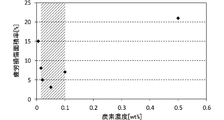
- FIG. 3 is a graph showing the relationship between the carbon concentration and the fatigue damage area ratio. As shown in the figure, it was found that the higher the carbon concentration, the better the fatigue resistance in the carbon concentration range of 0.03% by mass or less. It is considered that the coarsening of Cu 6 Bi 5 or Cu 3 Bi can be effectively suppressed as the carbon concentration increases. It was found that the lower the carbon concentration, the better the fatigue resistance in the range of carbon concentration greater than 0.03% by mass. It is considered that C could suppress the overlay 12 from becoming brittle as the carbon concentration becomes smaller.
- the second embodiment is common to the first embodiment in the configuration other than the overlay 12.
- the overlay 12 of the second embodiment will be described.
- the overlay 12 of the second embodiment is also a layer laminated on the inner surface of the lining 11, and constitutes the covering layer of the present invention.
- the covering layer includes Sn as a first metal element, Cu as a second metal element that forms an intermetallic compound with the first metal element, C, and an unavoidable impurity.
- the content of Cu is 3.0 wt%
- the content of C is 0.05 wt%
- the total content of unavoidable impurities is 1.0 wt% or less, the balance Is Sn.
- the fatigue damage area ratio was as good as 3.0%.
- an appropriate amount of C serves as a diffusion barrier and the intermetallic compound becomes coarse.
- Cu 6 Sn 5 or Cu 3 Sn is precipitated in the overlay 12 as an intermetallic compound, but C acts as a diffusion barrier, and coarsening of Cu 6 Sn 5 or Cu 3 Sn can be suppressed. This allows the interface between the soft Sn and the hard intermetallic compound to be kept at a small size. Therefore, even if a fatigue crack occurs at the interface between the soft Sn and the hard intermetallic compound, the possibility that the fatigue crack will greatly progress can be reduced, and the fatigue resistance can be improved.
- the overlay 12 of the second embodiment was formed by laminating Sn on the surface of the lining 11 by electroplating to a thickness of 10 ⁇ m.
- the procedure of electroplating was as follows. First, the surface of the lining 11 was washed with water. Furthermore, by pickling the surface of the lining 11, unnecessary oxide was removed from the surface of the lining 11. Thereafter, the surface of the lining 11 was washed again with water.
- electroplating was performed by supplying a current to the lining 11 immersed in the plating bath.
- the bath composition of a plating bath containing 28 g / l (Sn concentration) of stannous nitrate, 3 g / l (Cu concentration) of copper sulfate, 100 g / l of inorganic ammonium salt and 80 g / l of organic carboxylic acid.
- the bath temperature of the plating bath was 30.degree.
- the current supplied to the lining 11 is a direct current, and the current density is 2.0 A / dm 2 .
- Example 5 in which the concentration of organic carboxylic acid was changed to 20 g / l
- Example 6 in which the concentration of organic carboxylic acid was changed to 40 g / l
- concentration of organic carboxylic acid Example 7 (second embodiment) in which 80 g / l is used
- Example 8 in which the concentration of organic carboxylic acid is changed to 100 g / l
- Comparative Example 3 in which the concentration of organic carboxylic acid is changed to 200 g / l And prepared.
- Comparative Example 4 in which electroplating was performed in a plating bath of a borofluorination bath (tin borofluoride, copper borofluoride) was prepared.
- Table 2 shows the carbon concentration and the fatigue damage area ratio in the overlay 12 in Examples 5 to 7 and Comparative Examples 3 and 4.
- the carbon concentration and the fatigue damage area ratio were measured by the same method as in the first embodiment.
- the carbon concentration in the overlay 12 could be increased by increasing the concentration of the organic carboxylic acid in the plating bath.
- the carbon concentration in the overlay 12 could be made almost zero by using the plating bath containing no organic substance.
- FIG. 4 is a graph showing the relationship between the carbon concentration and the fatigue damage area rate in the second embodiment. As shown in the figure, it was found that in the range of the carbon concentration of 0.05 wt% or less, the higher the carbon concentration, the better the fatigue resistance. It is considered that the coarsening of Cu 6 Sn 5 or Cu 3 Sn can be effectively suppressed as the carbon concentration increases. It was found that the lower the carbon concentration, the better the fatigue resistance in the range of carbon concentration greater than 0.05 wt%. It is considered that C could suppress the overlay 12 from becoming brittle as the carbon concentration becomes smaller.
- an intermediate layer may be inserted between the lining 11 and the overlay 12.
- the intermediate layer is desirably formed of a material that can suppress the diffusion of the elements of the lining 11 into the overlay 12, and may be formed of, for example, Cu.
- the carbon concentration of the overlay 12 may not necessarily be adjusted by the carbon concentration in the electroplating plating bath, and the method of forming the overlay 12 is not limited to electroplating.
- the overlay 12 may be formed by sputtering or vapor deposition, and the carbon concentration may be adjusted when performing sputtering or vapor deposition.
- the carbon concentration may be increased by diffusion or the like.
- the sliding member 1 which comprises the sliding bearing A which bears the crankshaft of an engine was illustrated, you may form the sliding bearing A of another use by the sliding member 1 of this invention.
- the sliding member 1 of the present invention may form a radial bearing such as a gear bushing for a transmission or a piston pin bushing or boss bushing.
- the sliding member of the present invention may be a thrust bearing, may be various washers, or may be a swash plate for a car air conditioner compressor.
- the matrix of the lining 11 is not limited to the Cu alloy, and the material of the matrix may be selected according to the hardness of the mating shaft 2.
- the back metal 10 is not essential but may be omitted.
Abstract
[Problem] To provide a sliding member and a sliding bearing which are capable of improving fatigue resistance. [Solution] Provided is a sliding member in which a coating layer is laminated on a base layer, wherein the coating layer comprises: Bi or Sn as a first metal element; a second metal element which is harder than said first metal element and forms an intermetallic compound with said first metal element; C; and inevitable impurities.
Description
本発明は、摺動面にて相手材が摺動する摺動部材およびすべり軸受に関する。
The present invention relates to a sliding member and a sliding bearing in which a mating material slides on a sliding surface.
Cuを必須元素として含み、SnとInの少なくとも一方を含むBi合金で形成されたオーバーレイ層が知られている(特許文献1、参照。)。特許文献1において、Bi合金中にCuやSnやInが含まれることにより、耐疲労性が向上することが記載されている。また、軟質金属であるSnにCuを添加した錫基オーバーレイが知られている(特許文献2、参照。)。特許文献1において、Snに強化元素としてのCuを添加することにより、耐摩耗性や耐疲労性の向上が図られている。
An overlay layer formed of a Bi alloy containing Cu as an essential element and containing at least one of Sn and In is known (see Patent Document 1). Patent Document 1 describes that fatigue resistance is improved by containing Cu, Sn, or In in a Bi alloy. In addition, a tin-based overlay in which Cu is added to Sn which is a soft metal is known (see Patent Document 2). In Patent Document 1, the addition of Cu as a strengthening element to Sn improves the wear resistance and the fatigue resistance.
しかしながら、特許文献1のように、Bi合金中にCuが含まれると、却って耐疲労性が低下するという問題があった。オーバーレイ層に熱負荷がかかった場合に、BiとCuとによって硬質の金属間化合物が生成され、当該硬質の金属間化合物と軟質のBiとの界面においてクラックが発生しやすくなるからである。特に、金属間化合物が粗大化すると、オーバーレイ層中においてクラックが進展しやすくなり、耐疲労性が大きく低下してしまう。また、特許文献2の錫基オーバーレイの使用時等において熱負荷がかかった場合、耐疲労性が低下するという問題があった。特許文献1の錫基オーバーレイに熱負荷がかかると、SnとCuとによって硬質の金属間化合物が形成される。すると、硬質の金属間化合物と軟質のSnとの間において硬度差が大きく異なる界面が形成され、当該界面にて疲労クラックが発生しやすくなる。さらに、疲労クラックが金属間化合物とSnとの界面を進展することにより、耐疲労性が低下してしまう。
本発明は、前記課題にかんがみてなされたもので、オーバーレイの耐疲労性の向上を実現できる技術を提供することを目的とする。 However, as described in Patent Document 1, when Cu is contained in the Bi alloy, there is a problem that the fatigue resistance is reduced. When a thermal load is applied to the overlay layer, a hard intermetallic compound is generated by Bi and Cu, and a crack is easily generated at the interface between the hard intermetallic compound and the soft Bi. In particular, when the intermetallic compound is coarsened, the crack is likely to progress in the overlay layer, and the fatigue resistance is greatly reduced. In addition, when a thermal load is applied when using the tin base overlay ofPatent Document 2, there is a problem that the fatigue resistance is lowered. When a thermal load is applied to the tin-based overlay of Patent Document 1, a hard intermetallic compound is formed by Sn and Cu. Then, an interface having a large difference in hardness is formed between the hard intermetallic compound and the soft Sn, and a fatigue crack is easily generated at the interface. Furthermore, fatigue resistance is reduced by the progress of fatigue cracks at the interface between the intermetallic compound and Sn.
The present invention has been made in view of the above problems, and an object of the present invention is to provide a technique capable of realizing improvement in the fatigue resistance of an overlay.
本発明は、前記課題にかんがみてなされたもので、オーバーレイの耐疲労性の向上を実現できる技術を提供することを目的とする。 However, as described in Patent Document 1, when Cu is contained in the Bi alloy, there is a problem that the fatigue resistance is reduced. When a thermal load is applied to the overlay layer, a hard intermetallic compound is generated by Bi and Cu, and a crack is easily generated at the interface between the hard intermetallic compound and the soft Bi. In particular, when the intermetallic compound is coarsened, the crack is likely to progress in the overlay layer, and the fatigue resistance is greatly reduced. In addition, when a thermal load is applied when using the tin base overlay of
The present invention has been made in view of the above problems, and an object of the present invention is to provide a technique capable of realizing improvement in the fatigue resistance of an overlay.
前記の目的を達成するため、本発明の摺動部材およびすべり軸受は、基層上に被覆層が積層された摺動部材であって、被覆層は、第1金属元素としてのSnと、第1金属元素よりも硬質であり、かつ、当該第1金属元素と金属間化合物を形成する第2金属元素と、0.010質量%以上、かつ、0.080質量%以下のCと、不可避不純物と、からなる。
In order to achieve the above object, the sliding member and the sliding bearing of the present invention are sliding members in which a cover layer is laminated on a base layer, and the cover layer is made of Sn as a first metal element, A second metal element which is harder than the metal element and forms an intermetallic compound with the first metal element, 0.010 mass% or more and 0.080 mass% or less of C, and unavoidable impurities It consists of
前記の構成において、熱負荷がかかった際に、第1金属元素と第2金属元素とによって金属間化合物が形成されても、適度な量のCが拡散障壁となって金属間化合物が粗大化する可能性を低減できる。従って、軟質のBiと硬質の金属間化合物との界面を小規模な大きさに留めることができる。そのため、軟質のBiと硬質の金属間化合物との界面において疲労クラックが発生しても、当該疲労クラックが大きく進展する可能性を低減でき、耐疲労性を向上させることができる。
In the above configuration, even when an intermetallic compound is formed by the first metal element and the second metal element when a thermal load is applied, a proper amount of C acts as a diffusion barrier and the intermetallic compound becomes coarse. Can reduce the possibility of Therefore, the interface between the soft Bi and the hard intermetallic compound can be kept at a small size. Therefore, even if a fatigue crack is generated at the interface between the soft Bi and the hard intermetallic compound, the possibility that the fatigue crack is greatly developed can be reduced, and the fatigue resistance can be improved.
なお、Cを0.010質量%以上とすることにより金属間化合物の粗大化を抑制でき、Cを0.020質量%以上とすることがより望ましい。また、Cを0.080質量%以下とすることにより被覆層が脆くなることを抑制でき、Cを0.060質量%以下とすることがより望ましい。第2金属元素は、Biよりも硬質かつBiと金属間化合物を形成する元素であればよく、例えばAgやSbやNi等であってもよい。第2金属元素は、0.5質量%以上、かつ、5.0質量%以下であればよく、望ましくは1.0質量%以上、かつ、3.0質量%以下であってもよい。第1金属元素としてのBiは、第2金属元素とCと不可避不純物の残部を構成する。
In addition, coarsening of an intermetallic compound can be suppressed by making C into 0.010 mass% or more, and it is more desirable to make C into 0.020 mass% or more. Moreover, it can suppress that a coating layer becomes brittle by making C into 0.080 mass% or less, and it is more desirable to make C into 0.060 mass% or less. The second metal element may be any element that is harder than Bi and forms an intermetallic compound with Bi, and may be, for example, Ag, Sb, Ni or the like. The second metal element may be 0.5 mass% or more and 5.0 mass% or less, desirably 1.0 mass% or more and 3.0 mass% or less. Bi as the first metal element constitutes the balance of the second metal element, C, and the unavoidable impurities.
前記の目的を達成するため、本発明の摺動部材およびすべり軸受は、基層上に被覆層が積層された摺動部材であって、被覆層は、第1金属元素としてのSnと、第1金属元素よりも硬質であり、かつ、当該第1金属元素と金属間化合物を形成する第2金属元素と、0.015wt%以上、かつ、0.100wt%以下のCと、不可避不純物と、からなる。
In order to achieve the above object, the sliding member and the sliding bearing of the present invention are sliding members in which a cover layer is laminated on a base layer, and the cover layer is made of Sn as a first metal element, And a second metal element which is harder than the metal element and forms an intermetallic compound with the first metal element, 0.015 wt% or more and 0.100 wt% or less of C, and an unavoidable impurity. Become.
前記の構成において、熱負荷がかかった際に、第1金属元素と第2金属元素とによって金属間化合物が形成されても、適度な量のCが拡散障壁となって金属間化合物が粗大化する可能性を低減できる。従って、軟質のSnと硬質の金属間化合物との界面を小規模な大きさに留めることができる。そのため、軟質のSnと硬質の金属間化合物との界面において疲労クラックが発生しても、当該疲労クラックが大きく進展する可能性を低減でき、耐疲労性を向上させることができる。
In the above configuration, even when an intermetallic compound is formed by the first metal element and the second metal element when a thermal load is applied, a proper amount of C acts as a diffusion barrier and the intermetallic compound becomes coarse. Can reduce the possibility of Therefore, the interface between the soft Sn and the hard intermetallic compound can be kept at a small size. Therefore, even if a fatigue crack occurs at the interface between the soft Sn and the hard intermetallic compound, the possibility that the fatigue crack will greatly progress can be reduced, and the fatigue resistance can be improved.
なお、Cを0.015wt%以上とすることにより金属間化合物の粗大化を抑制でき、Cを0.02wt%以上とすることがより望ましい。また、Cを0.100wt%以下とすることにより被覆層が脆くなることを抑制でき、Cを0.075wt%以下とすることがより望ましい。第2金属元素は、Snよりも硬質かつSnと金属間化合物を形成する元素であればよく、例えばAgやSbやNi等であってもよい。第2金属元素は、0.5wt%以上、かつ、10.0wt%以下であればよく、望ましくは1.0wt%以上、かつ、5.0wt%以下であってもよい。第1金属元素としてのSnは、第2金属とCと不可避不純物の残部を構成する。
In addition, coarsening of an intermetallic compound can be suppressed by setting C to 0.015 wt% or more, and it is more preferable to set C to 0.02 wt% or more. Further, by setting C to 0.100 wt% or less, it is possible to suppress the coating layer from becoming brittle, and it is more desirable to set C to 0.075 wt% or less. The second metal element may be any element that is harder than Sn and forms an intermetallic compound with Sn, and may be, for example, Ag, Sb, or Ni. The second metal element may be 0.5 wt% or more and 10.0 wt% or less, and desirably 1.0 wt% or more and 5.0 wt% or less. Sn as the first metal element constitutes the balance of the second metal, C, and unavoidable impurities.
ここでは、下記の順序に従って本発明の実施の形態について説明する。
(1)第1実施形態:
(1-1)摺動部材の構成:
(1-2)計測方法:
(1-3)摺動部材の製造方法:
(2)実験結果:
(3)第2実施形態:
(4)他の実施形態: Here, embodiments of the present invention will be described in the following order.
(1) First Embodiment:
(1-1) Configuration of sliding member:
(1-2) Measurement method:
(1-3) Manufacturing Method of Sliding Member:
(2) Experimental results:
(3) Second Embodiment:
(4) Other embodiments:
(1)第1実施形態:
(1-1)摺動部材の構成:
図1は、本発明の一実施形態にかかる摺動部材1の斜視図である。摺動部材1は、裏金10とライニング11とオーバーレイ12とを含む。摺動部材1は、中空状の円筒を直径方向に2等分した半割形状の金属部材であり、断面が半円弧状となっている。2個の摺動部材1を円筒状になるように組み合わせることにより、すべり軸受Aが形成される。すべり軸受Aは内部に形成される中空部分にて円柱状の相手軸2(エンジンのクランクシャフト)を軸受けする。相手軸2の外径はすべり軸受Aの内径よりもわずかに小さく形成されている。相手軸2の外周面と、すべり軸受Aの内周面との間に形成される隙間に潤滑油(エンジンオイル)が供給される。その際に、すべり軸受Aの内周面上を相手軸2の外周面が摺動する。 (1) First Embodiment:
(1-1) Configuration of sliding member:
FIG. 1 is a perspective view of a sliding member 1 according to an embodiment of the present invention. The sliding member 1 includes aback metal 10, a lining 11 and an overlay 12. The sliding member 1 is a metal member in the shape of a half in which a hollow cylinder is divided into two in the diameter direction, and the cross section thereof has a semicircular arc shape. The sliding bearing A is formed by combining the two sliding members 1 in a cylindrical shape. The slide bearing A bears a cylindrical counterpart shaft 2 (engine crankshaft) at a hollow portion formed inside. The outer diameter of the mating shaft 2 is formed slightly smaller than the inner diameter of the slide bearing A. Lubricating oil (engine oil) is supplied to the gap formed between the outer peripheral surface of the countershaft 2 and the inner peripheral surface of the slide bearing A. At this time, the outer peripheral surface of the mating shaft 2 slides on the inner peripheral surface of the slide bearing A.
(1-1)摺動部材の構成:
図1は、本発明の一実施形態にかかる摺動部材1の斜視図である。摺動部材1は、裏金10とライニング11とオーバーレイ12とを含む。摺動部材1は、中空状の円筒を直径方向に2等分した半割形状の金属部材であり、断面が半円弧状となっている。2個の摺動部材1を円筒状になるように組み合わせることにより、すべり軸受Aが形成される。すべり軸受Aは内部に形成される中空部分にて円柱状の相手軸2(エンジンのクランクシャフト)を軸受けする。相手軸2の外径はすべり軸受Aの内径よりもわずかに小さく形成されている。相手軸2の外周面と、すべり軸受Aの内周面との間に形成される隙間に潤滑油(エンジンオイル)が供給される。その際に、すべり軸受Aの内周面上を相手軸2の外周面が摺動する。 (1) First Embodiment:
(1-1) Configuration of sliding member:
FIG. 1 is a perspective view of a sliding member 1 according to an embodiment of the present invention. The sliding member 1 includes a
摺動部材1は、曲率中心から遠い順に、裏金10とライニング11とオーバーレイ12とが順に積層された構造を有する。従って、裏金10が摺動部材1の最外層を構成し、オーバーレイ12が摺動部材1の最内層を構成する。裏金10とライニング11とオーバーレイ12とは、それぞれ円周方向において一定の厚みを有している。裏金10の厚みは1.8mmであり、ライニング11の厚みは0.2mmであり、オーバーレイ12の厚みは10μmである。オーバーレイ12の曲率中心側の表面の半径の2倍(摺動部材1の内径)は73mmである。以下、内側とは摺動部材1の曲率中心側を意味し、外側とは摺動部材1の曲率中心と反対側を意味することとする。オーバーレイ12の内側の表面は、相手軸2の摺動面を構成する。
The sliding member 1 has a structure in which the back metal 10, the lining 11 and the overlay 12 are sequentially stacked in order of distance from the center of curvature. Therefore, the back metal 10 constitutes the outermost layer of the sliding member 1, and the overlay 12 constitutes the innermost layer of the sliding member 1. The back metal 10, the lining 11 and the overlay 12 each have a constant thickness in the circumferential direction. The thickness of the back metal 10 is 1.8 mm, the thickness of the lining 11 is 0.2 mm, and the thickness of the overlay 12 is 10 μm. The double of the radius of the surface of the overlay 12 on the side of the center of curvature (the inner diameter of the sliding member 1) is 73 mm. Hereinafter, the inner side means the center of curvature of the sliding member 1, and the outer side means the side opposite to the center of curvature of the sliding member 1. The inner surface of the overlay 12 constitutes the sliding surface of the countershaft 2.
裏金10は、Cを0.15質量%含有し、Mnを0.06質量%含有し、残部がFeからなる鋼で形成されている。なお、裏金10は、ライニング11とオーバーレイ12とを介して相手軸2からの荷重を支持できる材料で形成されればよく、必ずしも鋼で形成されなくてもよい。
The back metal 10 is formed of steel containing 0.15 mass% of C, 0.06 mass% of Mn, and the balance of Fe. In addition, the back metal 10 should just be formed with the material which can support the load from the other axis | shaft 2 via the lining 11 and the overlay 12, and does not necessarily need to be formed with steel.
ライニング11は、裏金10の内側に積層された層であり、本発明の基層を構成する。ライニング11は、Snを10質量%含有し、Biを8質量%含有し、残部がCuと不可避不純物とからなる。ライニング11の不可避不純物はMg,Ti,B,Pb,Cr等であり、精錬もしくはスクラップにおいて混入する不純物である。ライニング11における不可避不純物の含有量は、全体で1.0質量%以下である。ライニング11は、上述した組成のものに限定されず、例えばBiとSnとInとNiの1種類以上と不可避不純物の総量が25質量%以下となるAl合金であってもよい。さらに、ライニング11は、Cu合金であってもよい。例えば、ライニング11は、SnとSiとZnとMgとCrとZrとNiとVの1種類以上と不可避不純物の総量が25質量%以下となるCu合金であってもよい。
The lining 11 is a layer laminated on the inner side of the back metal 10, and constitutes the base layer of the present invention. The lining 11 contains 10% by mass of Sn, 8% by mass of Bi, and the balance consists of Cu and unavoidable impurities. Unavoidable impurities of the lining 11 are Mg, Ti, B, Pb, Cr, etc., which are impurities mixed in refining or scrap. The content of unavoidable impurities in the lining 11 is 1.0 mass% or less in total. The lining 11 is not limited to the composition described above, and may be, for example, an Al alloy in which the total amount of one or more of Bi, Sn, In, and Ni and the unavoidable impurities is 25% by mass or less. Furthermore, the lining 11 may be a Cu alloy. For example, the lining 11 may be a Cu alloy in which the total amount of one or more of Sn, Si, Zn, Mg, Cr, Zr, Ni, and V and unavoidable impurities is 25% by mass or less.
オーバーレイ12は、ライニング11の内側の表面上に積層された層であり、本発明の被覆層を構成する。オーバーレイ12は、被覆層は、第1金属元素としてのBiと、当該第1金属元素と金属間化合物を形成する第2金属元素としてのNiと、Cと、不可避不純物と、からなる。本実施形態のオーバーレイ12において、Niの含有量は2.0質量%であり、Cの含有量は0.03質量%であり、不可避不純物の全体の含有量は1.0質量%以下であり、残部がBiとなっている。
The overlay 12 is a layer laminated on the inner surface of the lining 11 and constitutes the covering layer of the present invention. In the overlay 12, the covering layer is composed of Bi as a first metal element, Ni as a second metal element forming an intermetallic compound with the first metal element, C, and an unavoidable impurity. In the overlay 12 of the present embodiment, the content of Ni is 2.0% by mass, the content of C is 0.03% by mass, and the total content of unavoidable impurities is 1.0% by mass or less. The rest is Bi.
以上説明した摺動部材1と同様のオーバーレイ12を有する疲労試験片(コンロッドR)を作成し、その疲労損傷面積率を計測したところ、疲労損傷面積率は2.0%と良好であった。後述する疲労試験において熱負荷がかかった際に、第1金属元素と第2金属元素とによって金属間化合物が形成されても、適度な量のCが拡散障壁となって金属間化合物が粗大化する可能性を低減できる。本実施形態において、金属間化合物として、オーバーレイ12中にBi3Ni等が析出するが、Cが拡散障壁となってBi3Ni等の粗大化を抑制できる。これにより、軟質のBiと硬質の金属間化合物との界面を小規模な大きさに留めることができる。そのため、軟質のBiと硬質の金属間化合物との界面において疲労クラックが発生しても、当該疲労クラックが大きく進展する可能性を低減でき、耐疲労性を向上させることができる。
When a fatigue test piece (connecting rod R) having an overlay 12 similar to the sliding member 1 described above was produced and the fatigue damage area ratio was measured, the fatigue damage area ratio was as good as 2.0%. Even when an intermetallic compound is formed by the first metal element and the second metal element when a thermal load is applied in a fatigue test to be described later, an appropriate amount of C serves as a diffusion barrier and the intermetallic compound becomes coarse. Can reduce the possibility of In the present embodiment, Bi 3 Ni or the like is precipitated in the overlay 12 as an intermetallic compound, but C acts as a diffusion barrier, and coarsening of Bi 3 Ni or the like can be suppressed. This allows the interface between the soft Bi and the hard intermetallic compound to be kept at a small size. Therefore, even if a fatigue crack is generated at the interface between the soft Bi and the hard intermetallic compound, the possibility that the fatigue crack is greatly developed can be reduced, and the fatigue resistance can be improved.
(1-2)計測方法:
なお、疲労損傷面積率は、以下の手順で計測した。まず、図2に示すように、長さ方向の両端に円柱状の貫通穴が形成されたコンロッドRを用意し、一端の貫通穴にて試験軸H(ハッチング)を軸受けさせた。なお、試験軸Hを軸受けするコンロッドRの貫通穴の内周面に摺動部材1と同様のオーバーレイ12(黒色)を形成した。試験軸Hの軸方向におけるコンロッドRの両外側において試験軸Hを軸受けし、摺動速度が6.6m/秒となるように試験軸Hを回転させた。摺動速度とは、オーバーレイ12の表面と試験軸Hとの間の相対速度である。試験軸Hとは反対側のコンロッドRの端部を、コンロッドRの長さ方向に往復移動する移動体Fに連結し、当該移動体Fの往復荷重を57MPaとした。また、コンロッドRと試験軸Hとの間には、120℃のエンジンオイルを給油した。 (1-2) Measurement method:
In addition, the fatigue damage area rate was measured in the following procedures. First, as shown in FIG. 2, a connecting rod R in which cylindrical through holes were formed at both ends in the length direction was prepared, and a test axis H (hatching) was supported by the through holes at one end. An overlay 12 (black) similar to that of the sliding member 1 was formed on the inner peripheral surface of the through hole of the connecting rod R bearing the test axis H. The test axis H was supported on both outer sides of the connecting rod R in the axial direction of the test axis H, and the test axis H was rotated so that the sliding speed was 6.6 m / sec. The sliding speed is the relative speed between the surface of theoverlay 12 and the test axis H. The end of the connecting rod R opposite to the test axis H was connected to a moving body F reciprocating in the longitudinal direction of the connecting rod R, and the reciprocating load of the moving body F was 57 MPa. Further, engine oil at 120 ° C. was supplied between the connecting rod R and the test axis H.
なお、疲労損傷面積率は、以下の手順で計測した。まず、図2に示すように、長さ方向の両端に円柱状の貫通穴が形成されたコンロッドRを用意し、一端の貫通穴にて試験軸H(ハッチング)を軸受けさせた。なお、試験軸Hを軸受けするコンロッドRの貫通穴の内周面に摺動部材1と同様のオーバーレイ12(黒色)を形成した。試験軸Hの軸方向におけるコンロッドRの両外側において試験軸Hを軸受けし、摺動速度が6.6m/秒となるように試験軸Hを回転させた。摺動速度とは、オーバーレイ12の表面と試験軸Hとの間の相対速度である。試験軸Hとは反対側のコンロッドRの端部を、コンロッドRの長さ方向に往復移動する移動体Fに連結し、当該移動体Fの往復荷重を57MPaとした。また、コンロッドRと試験軸Hとの間には、120℃のエンジンオイルを給油した。 (1-2) Measurement method:
In addition, the fatigue damage area rate was measured in the following procedures. First, as shown in FIG. 2, a connecting rod R in which cylindrical through holes were formed at both ends in the length direction was prepared, and a test axis H (hatching) was supported by the through holes at one end. An overlay 12 (black) similar to that of the sliding member 1 was formed on the inner peripheral surface of the through hole of the connecting rod R bearing the test axis H. The test axis H was supported on both outer sides of the connecting rod R in the axial direction of the test axis H, and the test axis H was rotated so that the sliding speed was 6.6 m / sec. The sliding speed is the relative speed between the surface of the
以上の状態を50時間にわたって継続することにより、オーバーレイ12の疲労試験を行った。そして、疲労試験後において、オーバーレイ12の内側の表面(摺動面)を、当該表面に直交する直線上の位置から当該直線を主光軸とするように撮影し、当該撮影された画像である評価画像を得た。そして、評価画像に映し出されたオーバーレイ12の表面のうち損傷した部分をビノキュラー(拡大鏡)で観察して特定し、当該損傷した部分の面積である損傷部面積を、評価画像に映し出されたオーバーレイ12の表面全体の面積で除算した値の百分率を疲労損傷面積率として計測した。
The fatigue test of the overlay 12 was performed by continuing the above-mentioned state for 50 hours. Then, after the fatigue test, the inner surface (sliding surface) of the overlay 12 is photographed from the position on the straight line orthogonal to the surface, and the photographed straight line is taken as the main optical axis, and the photographed image is An evaluation image was obtained. Then, the damaged portion of the surface of the overlay 12 shown in the evaluation image is observed by a vincula (magnifying glass) and identified, and the damaged part area, which is the area of the damaged portion, is shown in the evaluation image The percentage of the value divided by the area of the entire surface of 12 was measured as the fatigue damage area rate.
上述した実施形態において示した各数値を以下の手法によって計測した。摺動部材1の各層を構成する元素の質量は、ICP発光分光分析装置(島津社製ICPS-8100)によって計測した。ただし、オーバーレイ12における炭素濃度は、高周波誘導加熱炉燃焼赤外線吸収法(JISG1211鉄鋼用炭素量分析方法)によって計測した。
Each numerical value shown in the embodiment described above was measured by the following method. The mass of the element constituting each layer of the sliding member 1 was measured by an ICP emission spectrometer (ICPS-8100 manufactured by Shimadzu Corporation). However, the carbon concentration in the overlay 12 was measured by a high frequency induction heating furnace combustion infrared absorption method (JIS G 1211 carbon content analysis method for steel).
各層の厚みは、以下の手順で計測した。まず、摺動部材1の軸方向の垂直断面をクロスセクションポリッシャ(日本電子製 IB-09010CP)で研磨した。そして、摺動部材1の断面を電子顕微鏡(日本電子製 JSM-6610A)によって7000倍の倍率で撮影することにより、観察画像(反射電子像)の画像データを得た。そして、観察画像を画像解析装置(ニレコ社製 ルーゼックス AP)によって解析することにより膜厚を計測した。
The thickness of each layer was measured by the following procedure. First, the vertical cross section of the sliding member 1 in the axial direction was polished with a cross section polisher (IB-09010 CP, manufactured by Nippon Denshi K.K.). Then, the cross section of the sliding member 1 was photographed with an electron microscope (JSM-6610A manufactured by JEOL) at a magnification of 7,000 times to obtain image data of an observation image (reflected electron image). Then, the film thickness was measured by analyzing the observation image with an image analyzer (Lusex AP manufactured by Nireco).
(1-3)摺動部材の製造方法:
まず、裏金10と同じ厚みを有する低炭素鋼の平面板を用意した。
次に、低炭素鋼で形成された平面板上に、ライニング11を構成する材料の粉末を散布する。具体的に、上述したライニング11における各成分の質量比となるように、Cuの粉末とBiの粉末とSnの粉末とを低炭素鋼の平面板上に散布した。ライニング11における各成分の質量比が満足できればよく、Cu-Bi,Cu-Sn等の合金粉末を低炭素鋼の平面板上に散布してもよい。粉末の粒径は、試験用ふるい(JIS Z8801)によって150μm以下に調整した。 (1-3) Manufacturing Method of Sliding Member:
First, a flat plate of low carbon steel having the same thickness as the backingmetal 10 was prepared.
Next, the powder of the material which comprises lining 11 is sprinkled on the plane board formed with low carbon steel. Specifically, Cu powder, Bi powder, and Sn powder were dispersed on a flat plate of low carbon steel so that the mass ratio of each component in the lining 11 described above was obtained. As long as the mass ratio of each component in the lining 11 can be satisfied, an alloy powder such as Cu—Bi, Cu—Sn may be dispersed on a flat plate of low carbon steel. The particle size of the powder was adjusted to 150 μm or less by a test sieve (JIS Z8801).
まず、裏金10と同じ厚みを有する低炭素鋼の平面板を用意した。
次に、低炭素鋼で形成された平面板上に、ライニング11を構成する材料の粉末を散布する。具体的に、上述したライニング11における各成分の質量比となるように、Cuの粉末とBiの粉末とSnの粉末とを低炭素鋼の平面板上に散布した。ライニング11における各成分の質量比が満足できればよく、Cu-Bi,Cu-Sn等の合金粉末を低炭素鋼の平面板上に散布してもよい。粉末の粒径は、試験用ふるい(JIS Z8801)によって150μm以下に調整した。 (1-3) Manufacturing Method of Sliding Member:
First, a flat plate of low carbon steel having the same thickness as the backing
Next, the powder of the material which comprises lining 11 is sprinkled on the plane board formed with low carbon steel. Specifically, Cu powder, Bi powder, and Sn powder were dispersed on a flat plate of low carbon steel so that the mass ratio of each component in the lining 11 described above was obtained. As long as the mass ratio of each component in the lining 11 can be satisfied, an alloy powder such as Cu—Bi, Cu—Sn may be dispersed on a flat plate of low carbon steel. The particle size of the powder was adjusted to 150 μm or less by a test sieve (JIS Z8801).
次に、低炭素鋼の平面板と、当該平面板上に散布した粉末とを焼結した。焼結温度を700~1000℃に制御し、不活性雰囲気中で焼結した。焼結後、冷却した。なお、ライニング11は必ずしも焼結によって形成されなくてもよく、鋳造等によって形成されてもよい。
Next, the flat plate of low carbon steel and the powder dispersed on the flat plate were sintered. The sintering temperature was controlled to 700 to 1000 ° C., and sintering was performed in an inert atmosphere. After sintering, it cooled. The lining 11 may not necessarily be formed by sintering, and may be formed by casting or the like.
冷却が完了すると、低炭素鋼の平面板上にCu合金層が形成される。このCu合金層には、冷却中に析出した軟質のBi粒子が含まれることとなる。
次に、中空状の円筒を直径方向に2等分した形状となるように、Cu合金層が形成された低炭素鋼をプレス加工した。このとき、低炭素鋼の外径が摺動部材1の外径と一致するようにプレス加工した。 When cooling is complete, a Cu alloy layer is formed on a flat plate of low carbon steel. The Cu alloy layer contains soft Bi particles precipitated during cooling.
Next, the low carbon steel on which the Cu alloy layer was formed was pressed so as to be a shape obtained by equally dividing the hollow cylinder into two in the diameter direction. At this time, pressing was performed so that the outer diameter of the low carbon steel matched the outer diameter of the sliding member 1.
次に、裏金10上に形成されたCu合金層の表面を切削加工した。このとき、裏金10上に形成されたCu合金層の厚みがライニング11と同一となるように、切削量を制御した。これにより、切削加工後のCu合金層によってライニング11が形成できる。切削加工は、例えば焼結ダイヤモンドで形成された切削工具材をセットした旋盤によって行った。切削加工後のライニング11の表面は、ライニング11とオーバーレイ12との界面を構成する。
Next, the surface of the Cu alloy layer formed on the back metal 10 was cut. At this time, the cutting amount was controlled so that the thickness of the Cu alloy layer formed on the back metal 10 was the same as that of the lining 11. Thereby, the lining 11 can be formed by the Cu alloy layer after cutting. The cutting process was performed by, for example, a lathe in which a cutting tool material formed of sintered diamond was set. The surface of the lining 11 after cutting forms an interface between the lining 11 and the overlay 12.
次に、ライニング11の表面上にBiを電気めっきによって10μmの厚みだけ積層することにより、オーバーレイ12を形成した。電気めっきの手順は以下のとおりとした。まず、ライニング11の表面を水洗した。さらに、ライニング11の表面を酸洗することにより、ライニング11の表面から不要な酸化物を除去した。その後、ライニング11の表面を、再度、水洗した。
Next, an overlay 12 was formed by laminating Bi to a thickness of 10 μm by electroplating on the surface of the lining 11. The procedure of electroplating was as follows. First, the surface of the lining 11 was washed with water. Furthermore, by pickling the surface of the lining 11, unnecessary oxide was removed from the surface of the lining 11. Thereafter, the surface of the lining 11 was washed again with water.
以上の前処理が完了すると、めっき浴に浸漬させたライニング11に電流を供給することにより電気めっきを行った。有機スルホン酸Bi:20g/l(Bi濃度)と硝酸Ni:1g/l(Ni濃度)と有機系界面活性剤:20ml/lと有機スルホン酸:100g/lとを含むめっき浴の浴組成とした。有機系界面活性剤は、ポリエチレングリコール溶液を使用した。めっき浴の浴温度を、30℃とした。さらに、ライニング11に供給する電流を直流電流とし、その電流密度を3.0A/dm2とした。電気めっきの完了後に、水洗と乾燥を行った。
When the above pretreatment was completed, electroplating was performed by supplying a current to the lining 11 immersed in the plating bath. A bath composition of a plating bath containing 20 g / l (Bi concentration) of organic sulfonic acid, Ni: 1 g / l (ni concentration) and Ni-based organic nitrate, 20 ml / l of organic surfactant and 100 g / l of organic sulfonic acid did. The organic surfactant used a polyethylene glycol solution. The bath temperature of the plating bath was 30.degree. Furthermore, the current supplied to the lining 11 is a direct current, and the current density is 3.0 A / dm 2 . After completion of the electroplating, water washing and drying were performed.
以上のようにして、摺動部材1を完成させると、2個の摺動部材1を円筒状に組み合わせることにより、すべり軸受Aを形成し、エンジンに取り付けた。
As described above, when the sliding member 1 is completed, the sliding bearing A is formed by combining the two sliding members 1 in a cylindrical shape and attached to the engine.
(2)実験結果:
第1実施形態と同様の電気めっきにおいて、有機系界面活性剤の濃度を5ml/lに変更した実施例1と、有機系界面活性剤の濃度を10ml/lに変更した実施例2と、有機系界面活性剤の濃度を20ml/lとした実施例3(第1実施形態)と、有機系界面活性剤の濃度を40ml/lに変更した実施例4と、有機系界面活性剤の濃度を80ml/lに変更した比較例1とを用意した。さらに、硫酸浴(硝酸Bi:30g/l(Bi濃度),硝酸Ni:2g/l(Ni濃度),硫酸:100g/l)のめっき浴にて電気めっきを行った比較例2を用意した。 (2) Experimental results:
In the same electroplating as in the first embodiment, Example 1 in which the concentration of the organic surfactant was changed to 5 ml / l, Example 2 in which the concentration of the organic surfactant was changed to 10 ml / l, and organic Example 3 (first embodiment) in which the concentration of the surfactant is 20 ml / l, Example 4 in which the concentration of the organic surfactant is changed to 40 ml / l, and the concentration of the organic surfactant The comparative example 1 changed to 80 ml / l was prepared. Further, Comparative Example 2 was prepared in which electroplating was performed in a plating bath of a sulfuric acid bath (Bi nitrate: 30 g / l (Bi concentration), Ni nitrate: 2 g / l (Ni concentration), sulfuric acid: 100 g / l).

図3は、炭素濃度と疲労損傷面積率との関係を示すグラフである。同図に示すように、0.03質量%以下の炭素濃度の範囲において、炭素濃度が大きくなるほど良好な耐疲労性を示すことが分かった。炭素濃度が大きくなるほど、効果的にCu6Bi5やCu3Biの粗大化を抑制できたものと考えられる。0.03質量%よりも大きい炭素濃度の範囲において、炭素濃度が小さいほど良好な耐疲労性を示すことが分かった。炭素濃度が小さくなるほど、Cによってオーバーレイ12が脆くなることを抑制できたものと考えられる。
FIG. 3 is a graph showing the relationship between the carbon concentration and the fatigue damage area ratio. As shown in the figure, it was found that the higher the carbon concentration, the better the fatigue resistance in the carbon concentration range of 0.03% by mass or less. It is considered that the coarsening of Cu 6 Bi 5 or Cu 3 Bi can be effectively suppressed as the carbon concentration increases. It was found that the lower the carbon concentration, the better the fatigue resistance in the range of carbon concentration greater than 0.03% by mass. It is considered that C could suppress the overlay 12 from becoming brittle as the carbon concentration becomes smaller.
また、図3のグラフにおいて、ハッチングで示すように、Cを0.010質量%以上し、Cを0.080質量%以下とすることが望ましいことが分かった。さらに、0.02質量%以上とすることがより望ましく、0.060質量%以下とすることがより望ましい。
Moreover, in the graph of FIG. 3, as shown by hatching, it turned out that it is desirable to make C 0.010 mass% or more and to make C 0.080 mass% or less. Furthermore, it is more preferable to set it as 0.02 mass% or more, and it is more preferable to set it as 0.060 mass% or less.
(3)第2実施形態:
第2実施形態は、オーバーレイ12以外の構成について第1実施形態と共通する。以下、第2実施形態のオーバーレイ12について説明する。第2実施形態のオーバーレイ12も、ライニング11の内側の表面上に積層された層であり、本発明の被覆層を構成する。第2実施形態のオーバーレイ12は、被覆層は、第1金属元素としてのSnと、当該第1金属元素と金属間化合物を形成する第2金属元素としてのCuと、Cと、不可避不純物と、からなる。第2実施形態のオーバーレイ12において、Cuの含有量は3.0wt%であり、Cの含有量は0.05wt%であり、不可避不純物の全体の含有量は1.0wt%以下であり、残部がSnとなっている。 (3) Second Embodiment:
The second embodiment is common to the first embodiment in the configuration other than theoverlay 12. Hereinafter, the overlay 12 of the second embodiment will be described. The overlay 12 of the second embodiment is also a layer laminated on the inner surface of the lining 11, and constitutes the covering layer of the present invention. In the overlay 12 of the second embodiment, the covering layer includes Sn as a first metal element, Cu as a second metal element that forms an intermetallic compound with the first metal element, C, and an unavoidable impurity. It consists of In the overlay 12 of the second embodiment, the content of Cu is 3.0 wt%, the content of C is 0.05 wt%, and the total content of unavoidable impurities is 1.0 wt% or less, the balance Is Sn.
第2実施形態は、オーバーレイ12以外の構成について第1実施形態と共通する。以下、第2実施形態のオーバーレイ12について説明する。第2実施形態のオーバーレイ12も、ライニング11の内側の表面上に積層された層であり、本発明の被覆層を構成する。第2実施形態のオーバーレイ12は、被覆層は、第1金属元素としてのSnと、当該第1金属元素と金属間化合物を形成する第2金属元素としてのCuと、Cと、不可避不純物と、からなる。第2実施形態のオーバーレイ12において、Cuの含有量は3.0wt%であり、Cの含有量は0.05wt%であり、不可避不純物の全体の含有量は1.0wt%以下であり、残部がSnとなっている。 (3) Second Embodiment:
The second embodiment is common to the first embodiment in the configuration other than the
以上説明した第2実施形態のオーバーレイ12を有する疲労試験片(コンロッドR)を作成し、その疲労損傷面積率を計測したところ、疲労損傷面積率は3.0%と良好であった。後述する疲労試験において熱負荷がかかった際に、第1金属元素と第2金属元素とによって金属間化合物が形成されても、適度な量のCが拡散障壁となって金属間化合物が粗大化する可能性を低減できる。第2実施形態において、金属間化合物として、オーバーレイ12中にCu6Sn5やCu3Snが析出するが、Cが拡散障壁となってCu6Sn5やCu3Snの粗大化を抑制できる。これにより、軟質のSnと硬質の金属間化合物との界面を小規模な大きさに留めることができる。そのため、軟質のSnと硬質の金属間化合物との界面において疲労クラックが発生しても、当該疲労クラックが大きく進展する可能性を低減でき、耐疲労性を向上させることができる。
When a fatigue test piece (connecting rod R) having the overlay 12 of the second embodiment described above was produced and the fatigue damage area ratio was measured, the fatigue damage area ratio was as good as 3.0%. Even when an intermetallic compound is formed by the first metal element and the second metal element when a thermal load is applied in a fatigue test to be described later, an appropriate amount of C serves as a diffusion barrier and the intermetallic compound becomes coarse. Can reduce the possibility of In the second embodiment, Cu 6 Sn 5 or Cu 3 Sn is precipitated in the overlay 12 as an intermetallic compound, but C acts as a diffusion barrier, and coarsening of Cu 6 Sn 5 or Cu 3 Sn can be suppressed. This allows the interface between the soft Sn and the hard intermetallic compound to be kept at a small size. Therefore, even if a fatigue crack occurs at the interface between the soft Sn and the hard intermetallic compound, the possibility that the fatigue crack will greatly progress can be reduced, and the fatigue resistance can be improved.
なお、ライニング11の表面上にSnを電気めっきによって10μmの厚みだけ積層することにより、第2実施形態のオーバーレイ12を形成した。電気めっきの手順は以下のとおりとした。まず、ライニング11の表面を水洗した。さらに、ライニング11の表面を酸洗することにより、ライニング11の表面から不要な酸化物を除去した。その後、ライニング11の表面を、再度、水洗した。
The overlay 12 of the second embodiment was formed by laminating Sn on the surface of the lining 11 by electroplating to a thickness of 10 μm. The procedure of electroplating was as follows. First, the surface of the lining 11 was washed with water. Furthermore, by pickling the surface of the lining 11, unnecessary oxide was removed from the surface of the lining 11. Thereafter, the surface of the lining 11 was washed again with water.
以上の前処理が完了すると、めっき浴に浸漬させたライニング11に電流を供給することにより電気めっきを行った。硝酸第一錫:28g/l(Sn濃度)と硫酸銅:3g/l(Cu濃度)と無機アンモニウム塩:100g/lと有機カルボン酸:80g/lとを含むめっき浴の浴組成とした。めっき浴の浴温度を、30℃とした。さらに、ライニング11に供給する電流を直流電流とし、その電流密度を2.0A/dm2とした。電気めっきの完了後に、水洗と乾燥を行った。
When the above pretreatment was completed, electroplating was performed by supplying a current to the lining 11 immersed in the plating bath. The bath composition of a plating bath containing 28 g / l (Sn concentration) of stannous nitrate, 3 g / l (Cu concentration) of copper sulfate, 100 g / l of inorganic ammonium salt and 80 g / l of organic carboxylic acid. The bath temperature of the plating bath was 30.degree. Furthermore, the current supplied to the lining 11 is a direct current, and the current density is 2.0 A / dm 2 . After completion of the electroplating, water washing and drying were performed.
第2実施形態と同様の電気めっきにおいて、有機カルボン酸の濃度を20g/lに変更した実施例5と、有機カルボン酸の濃度を40g/lに変更した実施例6と、有機カルボン酸の濃度を80g/lにとした実施例7(第2実施形態)と、有機カルボン酸の濃度を100g/lに変更した実施例8と、有機カルボン酸の濃度を200g/lに変更した比較例3とを用意した。さらに、ホウフッ化浴(ホウフッ化錫,ホウフッ化銅)のめっき浴にて電気めっきを行った比較例4を用意した。
In the same electroplating as in the second embodiment, Example 5 in which the concentration of organic carboxylic acid was changed to 20 g / l, Example 6 in which the concentration of organic carboxylic acid was changed to 40 g / l, and concentration of organic carboxylic acid Example 7 (second embodiment) in which 80 g / l is used, Example 8 in which the concentration of organic carboxylic acid is changed to 100 g / l, and Comparative Example 3 in which the concentration of organic carboxylic acid is changed to 200 g / l And prepared. Furthermore, Comparative Example 4 in which electroplating was performed in a plating bath of a borofluorination bath (tin borofluoride, copper borofluoride) was prepared.

図4は、第2実施形態における炭素濃度と疲労損傷面積率との関係を示すグラフである。同図に示すように、0.05wt%以下の炭素濃度の範囲において、炭素濃度が大きくなるほど良好な耐疲労性を示すことが分かった。炭素濃度が大きくなるほど、効果的にCu6Sn5やCu3Snの粗大化を抑制できたものと考えられる。0.05wt%よりも大きい炭素濃度の範囲において、炭素濃度が小さいほど良好な耐疲労性を示すことが分かった。炭素濃度が小さくなるほど、Cによってオーバーレイ12が脆くなることを抑制できたものと考えられる。
FIG. 4 is a graph showing the relationship between the carbon concentration and the fatigue damage area rate in the second embodiment. As shown in the figure, it was found that in the range of the carbon concentration of 0.05 wt% or less, the higher the carbon concentration, the better the fatigue resistance. It is considered that the coarsening of Cu 6 Sn 5 or Cu 3 Sn can be effectively suppressed as the carbon concentration increases. It was found that the lower the carbon concentration, the better the fatigue resistance in the range of carbon concentration greater than 0.05 wt%. It is considered that C could suppress the overlay 12 from becoming brittle as the carbon concentration becomes smaller.
また、図4のグラフにおいて、ハッチングで示すように、Cを0.015wt%以上とし、Cを0.100wt%以下とすることが望ましいことが分かった。さらに、0.02wt%以上とすることがより望ましく、0.075wt%以下とすることがより望ましい。
Further, as shown by hatching in the graph of FIG. 4, it was found that it is desirable to set C to 0.015 wt% or more and C to 0.100 wt% or less. Furthermore, it is more desirable to make it 0.02 wt% or more, and it is more desirable to make it 0.075 wt% or less.
(4)他の実施形態:
前記実施形態においては、第2金属元素としてCuを採用したが、Biよりも硬質(例えばモース硬度が大きい)な他の元素(Ag,Sb,Ni,Au等)を第2金属元素として採用してもよい。また、金属間化合物が形成されるのは必ずしも摺動部材1の使用時に限られない。例えば、摺動部材1の使用前において、予め熱処理を行うことにより、金属間化合物の析出を完了させておいてもよい。この場合も、適切な量のCによって金属間化合物の粗大化を抑制することができる。 (4) Other embodiments:
In the above embodiment, Cu is employed as the second metal element, but another element (Ag, Sb, Ni, Au, etc.) harder than Bi (for example, having a large Mohs hardness) is employed as the second metal element. May be The formation of the intermetallic compound is not necessarily limited to the use of the sliding member 1. For example, before using the sliding member 1, the precipitation of the intermetallic compound may be completed by performing a heat treatment in advance. Also in this case, coarsening of the intermetallic compound can be suppressed by an appropriate amount of C.
また、ライニング11とオーバーレイ12との間に中間層が挿入されてもよい。中間層は、ライニング11の元素がオーバーレイ12に拡散することを抑制できる材料によって形成されることが望ましく、例えばCuで形成されてもよい。オーバーレイ12の炭素濃度は、必ずしも電気めっきのめっき浴における炭素濃度によって調整されなくてもよく、オーバーレイ12の形成手法も電気めっきに限られない。例えば、オーバーレイ12をスパッタリングや蒸着によって形成してもよく、スパッタリングや蒸着を行う際に炭素濃度が調整されてもよい。さらに、炭素濃度が低いオーバーレイ12を形成した後に、拡散等によって炭素濃度を増加させるようにしてもよい。
Also, an intermediate layer may be inserted between the lining 11 and the overlay 12. The intermediate layer is desirably formed of a material that can suppress the diffusion of the elements of the lining 11 into the overlay 12, and may be formed of, for example, Cu. The carbon concentration of the overlay 12 may not necessarily be adjusted by the carbon concentration in the electroplating plating bath, and the method of forming the overlay 12 is not limited to electroplating. For example, the overlay 12 may be formed by sputtering or vapor deposition, and the carbon concentration may be adjusted when performing sputtering or vapor deposition. Furthermore, after the overlay 12 having a low carbon concentration is formed, the carbon concentration may be increased by diffusion or the like.
前記実施形態においては、エンジンのクランクシャフトを軸受けするすべり軸受Aを構成する摺動部材1を例示したが、本発明の摺動部材1によって他の用途のすべり軸受Aを形成してもよい。例えば、本発明の摺動部材1によってトランスミッション用のギヤブシュやピストンピンブシュ・ボスブシュ等のラジアル軸受を形成してもよい。さらに、本発明の摺動部材は、スラスト軸受であってもよく、各種ワッシャであってもよいし、カーエアコンコンプレッサ用の斜板であってもよい。また、ライニング11のマトリクスはCu合金に限られず、相手軸2の硬さに応じてマトリクスの材料が選択されればよい。また、裏金10は、必須ではなく省略されてもよい。
In the said embodiment, although the sliding member 1 which comprises the sliding bearing A which bears the crankshaft of an engine was illustrated, you may form the sliding bearing A of another use by the sliding member 1 of this invention. For example, the sliding member 1 of the present invention may form a radial bearing such as a gear bushing for a transmission or a piston pin bushing or boss bushing. Furthermore, the sliding member of the present invention may be a thrust bearing, may be various washers, or may be a swash plate for a car air conditioner compressor. Further, the matrix of the lining 11 is not limited to the Cu alloy, and the material of the matrix may be selected according to the hardness of the mating shaft 2. Also, the back metal 10 is not essential but may be omitted.
1…摺動部材、2…相手軸、10…裏金、11…ライニング、12…オーバーレイ、A…軸受、F…移動体、H…試験軸、R…コンロッド
DESCRIPTION OF SYMBOLS 1 ... Sliding member, 2 ... Countering axis, 10 ... Back metal, 11 ... Lining, 12 ... Overlay, A ... Bearing, F ... Moving body, H ... Test axis, R ... Connecting rod
Claims (4)
- 基層上に被覆層が積層された摺動部材であって、
前記被覆層は、
第1金属元素としてのBiと、
前記第1金属元素よりも硬質であり、かつ、当該第1金属元素と金属間化合物を形成する第2金属元素と、
0.010質量%以上、かつ、0.080質量%以下のCと、
不可避不純物と、
からなることを特徴とする摺動部材。 A sliding member in which a cover layer is laminated on a base layer,
The covering layer is
Bi as a first metal element,
A second metal element which is harder than the first metal element and which forms an intermetallic compound with the first metal element;
0.010 mass% or more and 0.080 mass% or less of C,
Unavoidable impurities,
A sliding member characterized by comprising: - 基層上に被覆層が積層されたすべり軸受であって、
前記被覆層は、
第1金属元素としてのBiと、
前記第1金属元素よりも硬質であり、かつ、当該第1金属元素と金属間化合物を形成する第2金属元素と、
0.010質量%以上、かつ、0.080質量%以下のCと、
不可避不純物と、
からなることを特徴とするすべり軸受。 A slide bearing in which a cover layer is laminated on a base layer,
The covering layer is
Bi as a first metal element,
A second metal element which is harder than the first metal element and which forms an intermetallic compound with the first metal element;
0.010 mass% or more and 0.080 mass% or less of C,
Unavoidable impurities,
A sliding bearing characterized by comprising: - 基層上に被覆層が積層された摺動部材であって、
前記被覆層は、
第1金属元素としてのSnと、
前記第1金属元素よりも硬質であり、かつ、当該第1金属元素と金属間化合物を形成する第2金属元素と、
0.015wt%以上、かつ、0.100wt%以下のCと、
不可避不純物と、
からなることを特徴とする摺動部材。 A sliding member in which a cover layer is laminated on a base layer,
The covering layer is
Sn as a first metal element,
A second metal element which is harder than the first metal element and which forms an intermetallic compound with the first metal element;
0.015 wt% or more and 0.100 wt% or less of C,
Unavoidable impurities,
A sliding member characterized by comprising: - 基層上に被覆層が積層されたすべり軸受であって、
前記被覆層は、
第1金属元素としてのSnと、
前記第1金属元素よりも硬質であり、かつ、当該第1金属元素と金属間化合物を形成する第2金属元素と、
0.015wt%以上、かつ、0.100wt%以下のCと、
不可避不純物と、
からなることを特徴とするすべり軸受。 A slide bearing in which a cover layer is laminated on a base layer,
The covering layer is
Sn as a first metal element,
A second metal element which is harder than the first metal element and which forms an intermetallic compound with the first metal element;
0.015 wt% or more and 0.100 wt% or less of C,
Unavoidable impurities,
A sliding bearing characterized by comprising:
Priority Applications (5)
| Application Number | Priority Date | Filing Date | Title |
|---|---|---|---|
| DE112018000075.3T DE112018000075T5 (en) | 2017-07-21 | 2018-06-29 | SLIDING BODIES AND SLIDING BEARINGS |
| US16/318,907 US11396910B2 (en) | 2017-07-21 | 2018-06-29 | Sliding member and sliding bearing |
| CN201880002598.4A CN109548407B (en) | 2017-07-21 | 2018-06-29 | Sliding member and sliding bearing |
| CN202110053178.2A CN112879436B (en) | 2017-07-21 | 2018-06-29 | Sliding member and sliding bearing |
| US17/070,032 US20210040988A1 (en) | 2017-07-21 | 2020-10-14 | Sliding member and sliding bearing |
Applications Claiming Priority (4)
| Application Number | Priority Date | Filing Date | Title |
|---|---|---|---|
| JP2017-141581 | 2017-07-21 | ||
| JP2017141581A JP6762915B2 (en) | 2017-07-21 | 2017-07-21 | Sliding members and plain bearings |
| JP2017-151239 | 2017-08-04 | ||
| JP2017151239A JP6895338B2 (en) | 2017-08-04 | 2017-08-04 | Sliding members and plain bearings |
Related Child Applications (2)
| Application Number | Title | Priority Date | Filing Date |
|---|---|---|---|
| US16/318,907 A-371-Of-International US11396910B2 (en) | 2017-07-21 | 2018-06-29 | Sliding member and sliding bearing |
| US17/070,032 Division US20210040988A1 (en) | 2017-07-21 | 2020-10-14 | Sliding member and sliding bearing |
Publications (1)
| Publication Number | Publication Date |
|---|---|
| WO2019017182A1 true WO2019017182A1 (en) | 2019-01-24 |
Family
ID=65015671
Family Applications (1)
| Application Number | Title | Priority Date | Filing Date |
|---|---|---|---|
| PCT/JP2018/024804 WO2019017182A1 (en) | 2017-07-21 | 2018-06-29 | Sliding member and sliding bearing |
Country Status (4)
| Country | Link |
|---|---|
| US (2) | US11396910B2 (en) |
| CN (2) | CN112879436B (en) |
| DE (1) | DE112018000075T5 (en) |
| WO (1) | WO2019017182A1 (en) |
Cited By (3)
| Publication number | Priority date | Publication date | Assignee | Title |
|---|---|---|---|---|
| WO2019239643A1 (en) * | 2018-06-13 | 2019-12-19 | 大豊工業株式会社 | Sliding member |
| WO2020166119A1 (en) * | 2019-02-15 | 2020-08-20 | 大豊工業株式会社 | Sliding member |
| CN113302343B (en) * | 2019-02-15 | 2024-04-19 | 大丰工业株式会社 | Sliding member |
Families Citing this family (1)
| Publication number | Priority date | Publication date | Assignee | Title |
|---|---|---|---|---|
| CN111549256B (en) * | 2020-06-24 | 2021-06-01 | 浙江省冶金研究院有限公司 | Method for improving performance of tin-based babbitt metal |
Citations (8)
| Publication number | Priority date | Publication date | Assignee | Title |
|---|---|---|---|---|
| JPH0552221A (en) * | 1991-08-22 | 1993-03-02 | Toshiba Corp | Sintered oil retaining bearing |
| JPH05117790A (en) * | 1991-10-23 | 1993-05-14 | Taiho Kogyo Co Ltd | Plain bearing |
| JPH1150296A (en) * | 1997-06-05 | 1999-02-23 | Toyota Motor Corp | Sliding member |
| JP2006105265A (en) * | 2004-10-05 | 2006-04-20 | Taiho Kogyo Co Ltd | Copper alloy based slide bearing |
| WO2009075314A1 (en) * | 2007-12-12 | 2009-06-18 | Shirogane Co., Ltd. | Solder alloy and process for producing the same |
| JP2011137227A (en) * | 2009-12-10 | 2011-07-14 | Miba Gleitlager Gmbh | Anti-friction coating |
| JP2011163382A (en) * | 2010-02-05 | 2011-08-25 | Daido Metal Co Ltd | Sliding member |
| JP2015096750A (en) * | 2013-11-15 | 2015-05-21 | 大豊工業株式会社 | Slide member and slide bearing |
Family Cites Families (20)
| Publication number | Priority date | Publication date | Assignee | Title |
|---|---|---|---|---|
| NL142657B (en) * | 1968-12-13 | 1974-07-15 | Euratom | PROCEDURE FOR IMPREGNATING AN OBJECT FROM GRAPHITE WITH METAL AND OBJECT OBTAINED BY THIS PROCEDURE. |
| EP0758721B1 (en) | 1995-03-01 | 2000-08-30 | Taiho Kogyo Co., Ltd. | Slide bearing |
| JPH10205539A (en) | 1997-01-22 | 1998-08-04 | Daido Metal Co Ltd | Copper base slide bearing |
| JP3472198B2 (en) * | 1999-06-09 | 2003-12-02 | 大同メタル工業株式会社 | Plain bearing |
| JP3754315B2 (en) | 2001-04-09 | 2006-03-08 | 大同メタル工業株式会社 | Multi-layer sliding material |
| GB2379449B (en) * | 2001-09-10 | 2003-10-08 | Daido Metal Co | Sliding member |
| JP2004308883A (en) | 2003-04-10 | 2004-11-04 | Daido Metal Co Ltd | Sliding member |
| JP3693256B2 (en) * | 2003-05-29 | 2005-09-07 | 大同メタル工業株式会社 | Sliding member |
| DE10337029B4 (en) | 2003-08-12 | 2009-06-04 | Federal-Mogul Wiesbaden Gmbh | Laminated composite, manufacture and use |
| EP2133580B1 (en) * | 2007-03-12 | 2014-09-10 | Taiho Kogyo Co., Ltd | Slide bearing |
| JP5117790B2 (en) * | 2007-07-11 | 2013-01-16 | 株式会社シンク・ラボラトリー | Negative photosensitive composition |
| AT506641B1 (en) * | 2008-04-07 | 2011-01-15 | Miba Gleitlager Gmbh | BEARINGS |
| US9683603B2 (en) * | 2008-05-15 | 2017-06-20 | Taiho Kogyo Co., Ltd. | Method for producing sliding member, sliding member, and substrate material of sliding member |
| AT509867B1 (en) * | 2010-04-15 | 2011-12-15 | Miba Gleitlager Gmbh | MULTILAYER BEARING BEARING WITH AN ANTIFRETTING LAYER |
| JP2012062942A (en) | 2010-09-15 | 2012-03-29 | Daido Metal Co Ltd | Sliding member |
| JP2012062941A (en) * | 2010-09-15 | 2012-03-29 | Daido Metal Co Ltd | Sliding member |
| JP6077481B2 (en) * | 2014-03-19 | 2017-02-08 | 大豊工業株式会社 | Plain bearing |
| GB2527368B (en) | 2014-06-20 | 2020-05-06 | Daido Metal Co | Structure and fabrication method of a multilayer overlay for plain bearings |
| GB2534120A (en) * | 2014-11-28 | 2016-07-20 | Daido Ind Bearings Europe Ltd | Bismuth-based composite coating for overlay applications in plain bearings |
| GB2533915A (en) * | 2014-11-28 | 2016-07-13 | Daido Metal Co | Overlay for sliding elements of machines such as internal combustion engines |
-
2018
- 2018-06-29 WO PCT/JP2018/024804 patent/WO2019017182A1/en active Application Filing
- 2018-06-29 CN CN202110053178.2A patent/CN112879436B/en active Active
- 2018-06-29 US US16/318,907 patent/US11396910B2/en active Active
- 2018-06-29 CN CN201880002598.4A patent/CN109548407B/en active Active
- 2018-06-29 DE DE112018000075.3T patent/DE112018000075T5/en active Pending
-
2020
- 2020-10-14 US US17/070,032 patent/US20210040988A1/en not_active Abandoned
Patent Citations (8)
| Publication number | Priority date | Publication date | Assignee | Title |
|---|---|---|---|---|
| JPH0552221A (en) * | 1991-08-22 | 1993-03-02 | Toshiba Corp | Sintered oil retaining bearing |
| JPH05117790A (en) * | 1991-10-23 | 1993-05-14 | Taiho Kogyo Co Ltd | Plain bearing |
| JPH1150296A (en) * | 1997-06-05 | 1999-02-23 | Toyota Motor Corp | Sliding member |
| JP2006105265A (en) * | 2004-10-05 | 2006-04-20 | Taiho Kogyo Co Ltd | Copper alloy based slide bearing |
| WO2009075314A1 (en) * | 2007-12-12 | 2009-06-18 | Shirogane Co., Ltd. | Solder alloy and process for producing the same |
| JP2011137227A (en) * | 2009-12-10 | 2011-07-14 | Miba Gleitlager Gmbh | Anti-friction coating |
| JP2011163382A (en) * | 2010-02-05 | 2011-08-25 | Daido Metal Co Ltd | Sliding member |
| JP2015096750A (en) * | 2013-11-15 | 2015-05-21 | 大豊工業株式会社 | Slide member and slide bearing |
Cited By (9)
| Publication number | Priority date | Publication date | Assignee | Title |
|---|---|---|---|---|
| WO2019239643A1 (en) * | 2018-06-13 | 2019-12-19 | 大豊工業株式会社 | Sliding member |
| JP2019214771A (en) * | 2018-06-13 | 2019-12-19 | 大豊工業株式会社 | Slide member |
| US10982712B2 (en) | 2018-06-13 | 2021-04-20 | Taiho Kogyo Co., Ltd. | Sliding member |
| WO2020166119A1 (en) * | 2019-02-15 | 2020-08-20 | 大豊工業株式会社 | Sliding member |
| JP2020132924A (en) * | 2019-02-15 | 2020-08-31 | 大豊工業株式会社 | Sliding member |
| CN113302343A (en) * | 2019-02-15 | 2021-08-24 | 大丰工业株式会社 | Sliding member |
| JP7195172B2 (en) | 2019-02-15 | 2022-12-23 | 大豊工業株式会社 | sliding member |
| US11959518B2 (en) | 2019-02-15 | 2024-04-16 | Taiho Kogyo Co., Ltd. | Sliding member |
| CN113302343B (en) * | 2019-02-15 | 2024-04-19 | 大丰工业株式会社 | Sliding member |
Also Published As
| Publication number | Publication date |
|---|---|
| US11396910B2 (en) | 2022-07-26 |
| CN109548407A (en) | 2019-03-29 |
| DE112018000075T5 (en) | 2019-06-06 |
| CN112879436A (en) | 2021-06-01 |
| CN109548407B (en) | 2021-05-14 |
| US20190203769A1 (en) | 2019-07-04 |
| CN112879436B (en) | 2023-04-25 |
| US20210040988A1 (en) | 2021-02-11 |
Similar Documents
| Publication | Publication Date | Title |
|---|---|---|
| US20210040988A1 (en) | Sliding member and sliding bearing | |
| JP6636090B2 (en) | Sliding member | |
| JP6621562B1 (en) | Sliding member | |
| JP6895338B2 (en) | Sliding members and plain bearings | |
| WO2019198285A1 (en) | Sliding member | |
| JP6516403B2 (en) | Sliding member and sliding bearing | |
| WO2018235529A1 (en) | Sliding member and slide bearing | |
| JP6944019B2 (en) | Sliding members and plain bearings | |
| JP6762915B2 (en) | Sliding members and plain bearings | |
| JP6321436B2 (en) | Sliding member and plain bearing | |
| CN113302343B (en) | Sliding member | |
| JP7195172B2 (en) | sliding member | |
| US20230235787A1 (en) | Sliding member | |
| JP6924315B2 (en) | Sliding members and plain bearings | |
| JP2019123914A (en) | Slide member |
Legal Events
| Date | Code | Title | Description |
|---|---|---|---|
| 121 | Ep: the epo has been informed by wipo that ep was designated in this application |
Ref document number: 18835383 Country of ref document: EP Kind code of ref document: A1 |
|
| 122 | Ep: pct application non-entry in european phase |
Ref document number: 18835383 Country of ref document: EP Kind code of ref document: A1 |