WO2019017095A1 - 情報処理装置、情報処理方法、プログラム、情報処理システム - Google Patents
情報処理装置、情報処理方法、プログラム、情報処理システム Download PDFInfo
- Publication number
- WO2019017095A1 WO2019017095A1 PCT/JP2018/021404 JP2018021404W WO2019017095A1 WO 2019017095 A1 WO2019017095 A1 WO 2019017095A1 JP 2018021404 W JP2018021404 W JP 2018021404W WO 2019017095 A1 WO2019017095 A1 WO 2019017095A1
- Authority
- WO
- WIPO (PCT)
- Prior art keywords
- vegetation
- data
- information
- light
- ratio
- Prior art date
Links
- 230000010365 information processing Effects 0.000 title claims description 89
- 238000003672 processing method Methods 0.000 title claims description 6
- 238000000605 extraction Methods 0.000 claims abstract description 105
- 230000008859 change Effects 0.000 claims abstract description 101
- 238000001514 detection method Methods 0.000 claims description 76
- 238000012545 processing Methods 0.000 claims description 68
- 238000004364 calculation method Methods 0.000 claims description 57
- 230000007613 environmental effect Effects 0.000 claims description 56
- 238000000034 method Methods 0.000 claims description 56
- 230000008569 process Effects 0.000 claims description 49
- 230000000903 blocking effect Effects 0.000 claims description 13
- 239000000284 extract Substances 0.000 abstract description 21
- 238000003384 imaging method Methods 0.000 description 64
- 238000004891 communication Methods 0.000 description 23
- 238000006243 chemical reaction Methods 0.000 description 17
- 230000000875 corresponding effect Effects 0.000 description 12
- 229930002875 chlorophyll Natural products 0.000 description 11
- 235000019804 chlorophyll Nutrition 0.000 description 11
- ATNHDLDRLWWWCB-AENOIHSZSA-M chlorophyll a Chemical compound C1([C@@H](C(=O)OC)C(=O)C2=C3C)=C2N2C3=CC(C(CC)=C3C)=[N+]4C3=CC3=C(C=C)C(C)=C5N3[Mg-2]42[N+]2=C1[C@@H](CCC(=O)OC\C=C(/C)CCC[C@H](C)CCC[C@H](C)CCCC(C)C)[C@H](C)C2=C5 ATNHDLDRLWWWCB-AENOIHSZSA-M 0.000 description 11
- 238000005516 engineering process Methods 0.000 description 11
- 239000013598 vector Substances 0.000 description 10
- 230000006870 function Effects 0.000 description 8
- 241000196324 Embryophyta Species 0.000 description 7
- 230000000694 effects Effects 0.000 description 7
- 238000005259 measurement Methods 0.000 description 7
- FFBHFFJDDLITSX-UHFFFAOYSA-N benzyl N-[2-hydroxy-4-(3-oxomorpholin-4-yl)phenyl]carbamate Chemical compound OC1=C(NC(=O)OCC2=CC=CC=C2)C=CC(=C1)N1CCOCC1=O FFBHFFJDDLITSX-UHFFFAOYSA-N 0.000 description 6
- 238000012937 correction Methods 0.000 description 6
- 230000003287 optical effect Effects 0.000 description 5
- 238000010586 diagram Methods 0.000 description 4
- 230000002354 daily effect Effects 0.000 description 3
- 230000004907 flux Effects 0.000 description 3
- 238000012986 modification Methods 0.000 description 3
- 230000004048 modification Effects 0.000 description 3
- 230000000243 photosynthetic effect Effects 0.000 description 3
- 230000007704 transition Effects 0.000 description 3
- 208000005156 Dehydration Diseases 0.000 description 2
- 239000002131 composite material Substances 0.000 description 2
- 238000005286 illumination Methods 0.000 description 2
- KBPHJBAIARWVSC-RGZFRNHPSA-N lutein Chemical compound C([C@H](O)CC=1C)C(C)(C)C=1\C=C\C(\C)=C\C=C\C(\C)=C\C=C\C=C(/C)\C=C\C=C(/C)\C=C\[C@H]1C(C)=C[C@H](O)CC1(C)C KBPHJBAIARWVSC-RGZFRNHPSA-N 0.000 description 2
- 229960005375 lutein Drugs 0.000 description 2
- 239000002245 particle Substances 0.000 description 2
- 230000036619 pore blockages Effects 0.000 description 2
- KBPHJBAIARWVSC-XQIHNALSSA-N trans-lutein Natural products CC(=C/C=C/C=C(C)/C=C/C=C(C)/C=C/C1=C(C)CC(O)CC1(C)C)C=CC=C(/C)C=CC2C(=CC(O)CC2(C)C)C KBPHJBAIARWVSC-XQIHNALSSA-N 0.000 description 2
- FJHBOVDFOQMZRV-XQIHNALSSA-N xanthophyll Natural products CC(=C/C=C/C=C(C)/C=C/C=C(C)/C=C/C1=C(C)CC(O)CC1(C)C)C=CC=C(/C)C=CC2C=C(C)C(O)CC2(C)C FJHBOVDFOQMZRV-XQIHNALSSA-N 0.000 description 2
- 235000008210 xanthophylls Nutrition 0.000 description 2
- 244000025254 Cannabis sativa Species 0.000 description 1
- 230000009471 action Effects 0.000 description 1
- 238000004458 analytical method Methods 0.000 description 1
- 238000004590 computer program Methods 0.000 description 1
- 230000001276 controlling effect Effects 0.000 description 1
- 230000002596 correlated effect Effects 0.000 description 1
- 238000013500 data storage Methods 0.000 description 1
- 238000005401 electroluminescence Methods 0.000 description 1
- 238000011156 evaluation Methods 0.000 description 1
- 230000003203 everyday effect Effects 0.000 description 1
- 230000007717 exclusion Effects 0.000 description 1
- 239000003337 fertilizer Substances 0.000 description 1
- 239000004973 liquid crystal related substance Substances 0.000 description 1
- 238000007726 management method Methods 0.000 description 1
- 230000007246 mechanism Effects 0.000 description 1
- 230000001151 other effect Effects 0.000 description 1
- 230000002093 peripheral effect Effects 0.000 description 1
- 230000029553 photosynthesis Effects 0.000 description 1
- 238000010672 photosynthesis Methods 0.000 description 1
- 238000007639 printing Methods 0.000 description 1
- 230000003252 repetitive effect Effects 0.000 description 1
- 230000002441 reversible effect Effects 0.000 description 1
- 230000000630 rising effect Effects 0.000 description 1
- 239000004065 semiconductor Substances 0.000 description 1
- 239000002689 soil Substances 0.000 description 1
- 230000003595 spectral effect Effects 0.000 description 1
- 238000001228 spectrum Methods 0.000 description 1
- 230000001360 synchronised effect Effects 0.000 description 1
- 238000012546 transfer Methods 0.000 description 1
Images


Classifications
-
- G—PHYSICS
- G01—MEASURING; TESTING
- G01J—MEASUREMENT OF INTENSITY, VELOCITY, SPECTRAL CONTENT, POLARISATION, PHASE OR PULSE CHARACTERISTICS OF INFRARED, VISIBLE OR ULTRAVIOLET LIGHT; COLORIMETRY; RADIATION PYROMETRY
- G01J3/00—Spectrometry; Spectrophotometry; Monochromators; Measuring colours
- G01J3/02—Details
- G01J3/0297—Constructional arrangements for removing other types of optical noise or for performing calibration
-
- G—PHYSICS
- G06—COMPUTING; CALCULATING OR COUNTING
- G06T—IMAGE DATA PROCESSING OR GENERATION, IN GENERAL
- G06T7/00—Image analysis
- G06T7/0002—Inspection of images, e.g. flaw detection
-
- G—PHYSICS
- G01—MEASURING; TESTING
- G01J—MEASUREMENT OF INTENSITY, VELOCITY, SPECTRAL CONTENT, POLARISATION, PHASE OR PULSE CHARACTERISTICS OF INFRARED, VISIBLE OR ULTRAVIOLET LIGHT; COLORIMETRY; RADIATION PYROMETRY
- G01J1/00—Photometry, e.g. photographic exposure meter
- G01J1/02—Details
- G01J1/04—Optical or mechanical part supplementary adjustable parts
- G01J1/0488—Optical or mechanical part supplementary adjustable parts with spectral filtering
-
- G—PHYSICS
- G01—MEASURING; TESTING
- G01J—MEASUREMENT OF INTENSITY, VELOCITY, SPECTRAL CONTENT, POLARISATION, PHASE OR PULSE CHARACTERISTICS OF INFRARED, VISIBLE OR ULTRAVIOLET LIGHT; COLORIMETRY; RADIATION PYROMETRY
- G01J1/00—Photometry, e.g. photographic exposure meter
- G01J1/42—Photometry, e.g. photographic exposure meter using electric radiation detectors
- G01J1/4204—Photometry, e.g. photographic exposure meter using electric radiation detectors with determination of ambient light
-
- G—PHYSICS
- G01—MEASURING; TESTING
- G01N—INVESTIGATING OR ANALYSING MATERIALS BY DETERMINING THEIR CHEMICAL OR PHYSICAL PROPERTIES
- G01N21/00—Investigating or analysing materials by the use of optical means, i.e. using sub-millimetre waves, infrared, visible or ultraviolet light
- G01N21/17—Systems in which incident light is modified in accordance with the properties of the material investigated
- G01N21/25—Colour; Spectral properties, i.e. comparison of effect of material on the light at two or more different wavelengths or wavelength bands
- G01N21/27—Colour; Spectral properties, i.e. comparison of effect of material on the light at two or more different wavelengths or wavelength bands using photo-electric detection ; circuits for computing concentration
-
- G—PHYSICS
- G06—COMPUTING; CALCULATING OR COUNTING
- G06T—IMAGE DATA PROCESSING OR GENERATION, IN GENERAL
- G06T7/00—Image analysis
- G06T7/97—Determining parameters from multiple pictures
-
- G—PHYSICS
- G06—COMPUTING; CALCULATING OR COUNTING
- G06V—IMAGE OR VIDEO RECOGNITION OR UNDERSTANDING
- G06V20/00—Scenes; Scene-specific elements
- G06V20/10—Terrestrial scenes
- G06V20/17—Terrestrial scenes taken from planes or by drones
-
- G—PHYSICS
- G06—COMPUTING; CALCULATING OR COUNTING
- G06V—IMAGE OR VIDEO RECOGNITION OR UNDERSTANDING
- G06V20/00—Scenes; Scene-specific elements
- G06V20/10—Terrestrial scenes
- G06V20/188—Vegetation
-
- G—PHYSICS
- G01—MEASURING; TESTING
- G01J—MEASUREMENT OF INTENSITY, VELOCITY, SPECTRAL CONTENT, POLARISATION, PHASE OR PULSE CHARACTERISTICS OF INFRARED, VISIBLE OR ULTRAVIOLET LIGHT; COLORIMETRY; RADIATION PYROMETRY
- G01J1/00—Photometry, e.g. photographic exposure meter
- G01J1/42—Photometry, e.g. photographic exposure meter using electric radiation detectors
- G01J2001/4266—Photometry, e.g. photographic exposure meter using electric radiation detectors for measuring solar light
- G01J2001/428—Photometry, e.g. photographic exposure meter using electric radiation detectors for measuring solar light for sunlight scattered by atmosphere
-
- G—PHYSICS
- G06—COMPUTING; CALCULATING OR COUNTING
- G06T—IMAGE DATA PROCESSING OR GENERATION, IN GENERAL
- G06T2207/00—Indexing scheme for image analysis or image enhancement
- G06T2207/10—Image acquisition modality
- G06T2207/10016—Video; Image sequence
-
- G—PHYSICS
- G06—COMPUTING; CALCULATING OR COUNTING
- G06T—IMAGE DATA PROCESSING OR GENERATION, IN GENERAL
- G06T2207/00—Indexing scheme for image analysis or image enhancement
- G06T2207/10—Image acquisition modality
- G06T2207/10032—Satellite or aerial image; Remote sensing
-
- G—PHYSICS
- G06—COMPUTING; CALCULATING OR COUNTING
- G06T—IMAGE DATA PROCESSING OR GENERATION, IN GENERAL
- G06T2207/00—Indexing scheme for image analysis or image enhancement
- G06T2207/30—Subject of image; Context of image processing
- G06T2207/30181—Earth observation
- G06T2207/30188—Vegetation; Agriculture
Definitions
- the present technology relates to an information processing apparatus, an information processing method, a program, and an information processing system, and more particularly to a technology suitable for generating vegetation change information that presents a change in vegetation state.
- Patent No. 5162890 gazette
- Vegetation index can be measured from the image of vegetation in the field. For example, if the Vegetation Index is obtained from the image taken on a daily basis, it generates vegetation change information that presents changes in vegetation state over time. can do. For example, it is possible to confirm the change of the vegetation state by obtaining an NDVI (Normalized Difference Vegetation Index) as a vegetation index and arranging them in time series.
- NDVI Normalized Difference Vegetation Index
- the vegetation index such as NDVI, it has been found that the value fluctuates due to the difference in conditions such as weather (fine / cloudy weather).
- the vegetation change information in which the NDVIs are arranged in time series includes a change in value due to the weather. For this reason, workers can not grasp the change of vegetation day by day correctly even if they look at the vegetation change information. So, in this technique, it enables it to be able to generate the vegetation change information which is hard to receive change by conditions, such as the weather, and it aims at enabling it to show a change of the vegetation condition in time series appropriately.
- An information processing apparatus extracts at least a part of vegetation data based on the ratio information from vegetation data at a plurality of points in time in which ratio information which is a component ratio of environmental light is associated. Is equipped. That is, while having the vegetation data of each time, the data group to which the component ratio (ratio information) of the environmental light at the time of the observation is made into the processing object. In this case, vegetation data suitable for output is extracted according to the ratio information.
- the above-described information processing apparatus further includes a generation unit that generates vegetation change information indicating a change in the vegetation data in time series, using the vegetation data extracted by the extraction unit. That is, the vegetation change information is generated using the vegetation data suitable for the output extracted by the extraction unit based on the ratio information.
- the extraction unit may perform processing of excluding vegetation data whose value of the associated ratio information is determined to be around a specific value by comparison with a threshold from vegetation data to be used. Conceivable. For example, when the ratio information is (directly transmitted light) / (scattered light), the ratio information is around 0 in cloudy weather. In addition, for example, when the ratio information is (total sky light) / (scattered light), the ratio information is around 1 in cloudy weather. The “0” or “1” is set as a specific value, and vegetation data in which the ratio information has a specific value or a value close to the specific value is excluded.
- the extraction unit performs a process of extracting vegetation data in which the value of the associated ratio information has a difference of a predetermined value or more with respect to a specific value. For example, when calculating the ratio information so that the ratio information is "0" or "1" when it is cloudy, the "0" or “1” is set as a specific value, and the ratio information is sufficiently away from the specific value. It extracts as vegetation data (or its candidate) which uses the vegetation data used as a value.
- the extraction unit may perform a process of extracting a plurality of vegetation data which are determined to be close to each other by comparing the value of the associated ratio information with a threshold value.
- the fact that the ratio information, which is the component ratio of the environmental light, is close means that the state of the environmental light at the time of observation for vegetation data calculation is similar.
- the extraction unit performs a process of extracting vegetation data in which the value of the associated ratio information is determined to be near a specific value by comparison with a threshold value. For example, when calculating ratio information so that the ratio information is "0" or "1" at cloudy weather, these "0" or “1” are specified values and the ratio information is a value near the specified value. Extract as vegetation data (or its candidate) using the existing vegetation data.
- the extraction condition of the extraction process by the extraction unit can be variably set.
- exclusion of vegetation data in which ratio information is close to a specified value extraction of vegetation data in which ratio information is sufficiently far from a specified value, extraction of multiple vegetation data in which ratio information is close to it, extraction of vegetation data in which ratio information is close to specified value , Etc. can be variably set by user operation or the like.
- the generation unit converts the vegetation data extracted by the extraction unit into a value when the ratio information is constant, and generates vegetation change information using the converted vegetation data. Is considered. For example, although vegetation change information is generated using vegetation data having similar extracted ratio information, the vegetation data is converted into a state in which the ratio information has a constant value.
- the above-described information processing apparatus may be provided with a vegetation data calculation unit that calculates vegetation data using observation data of vegetation at each time point. That is, vegetation data at each time point is generated in the information processing apparatus.
- the vegetation data calculation unit obtains the value of NDVI as vegetation data. That is, the value of NDVI which is a vegetation index is determined, and vegetation change information as change of this NDVI is generated.
- the above-described information processing apparatus is considered to include a ratio calculation unit that calculates ratio information, which is a component ratio of environmental light, using the detection value of environmental light corresponding to the vegetation data at each time, using the detected value of the environmental light Be That is, ratio information corresponding to vegetation data at each time is generated in the information processing apparatus.
- the ratio information is calculated using the detection value used to generate the vegetation data and the light detection value obtained substantially at the same time.
- the ratio calculation unit It is conceivable to calculate ratio information using detection values of each light receiving unit obtained by an environmental light sensor having a light receiving unit that is shaded by a light blocking unit and a light receiving unit that is not affected by the light blocking unit.
- the light shield allows detection of direct light and scattered light using an environmental light sensor mounted on the aircraft.
- the information processing method extracts vegetation data to be used using ratio information for a data group having vegetation data at a plurality of points in time in which ratio information that is a component ratio of environmental light is associated with each. It is an information processing method in which an information processing apparatus executes processing. Thus, it is possible to extract vegetation data for generating vegetation change information which is less susceptible to environmental conditions in the information processing apparatus.
- the program according to the present technology is a process for extracting vegetation data to be used using ratio information for a data group having vegetation data at a plurality of points in time, each being associated with ratio information that is a component ratio of environmental light It is a program to be executed by a computer device.
- An information processing system includes an environmental light sensor having a light receiving portion that is shaded by a light blocking body and a light receiving portion that is not affected by the light blocking body, the ratio calculating portion, the extracting portion, and the generating portion. Prepare. This makes it possible to construct a system suitable for generating vegetation change information that is less susceptible to environmental conditions.
- the present technology there is an effect that it is possible to generate vegetation change information in which changes due to conditions such as weather are less likely to appear, and changes in vegetation state can be accurately presented over time.
- the effect described here is not necessarily limited, and may be any effect described in the present disclosure.
- FIG. 1 shows the appearance of the farm field 210.
- the small-sized flying object 200 can move over the agricultural field 210 by, for example, radio control of the operator or radio automatic control.
- An imaging device 250 is set to, for example, the lower side of the flying object 300.
- the imaging device 250 periodically performs, for example, still image capturing or moving image capturing, so that the range W of the imaging field of view at each time point You can get an image.
- an image file (captured image at a certain point in time) obtained by imaging of the imaging device 250 includes a spectroscopic measurement image. That is, the imaging device 250 is a multi-spectrum camera, and an image to be captured may include a measurement image having information of two or more specific wavelength regions. Further, as the imaging device 250, a camera for capturing a visible light image of R (red), G (green), and B (blue) may be used.
- a camera that obtains a captured image of a red wavelength region (RED) and a near infrared region (NIR: Near Infra Red) may be used, which can calculate NDVI from the obtained image.
- NDVI is an index showing the distribution status and activity of vegetation.
- the imaging device 250 will be described as a camera that can obtain captured images of a red wavelength region (RED) and a near infrared region (NIR).
- tag information is added to an image obtained by imaging with the imaging device 250.
- the tag information includes imaging date and time information, position information (latitude / longitude information) as GPS (Global Positioning System) data, imaging device information (camera identification information, model information, etc.), information (image size of each image data) , Wavelength, information such as imaging parameters), and the like.
- the ambient light sensor 260 is mounted on the flying object 200 together with the imaging device 250.
- two ambient light sensors 260A and 260B are mounted on the upper surface side of the flying object 200.
- environmental light sensor 260 When one or more ambient light sensors to be used are collectively referred to, they are referred to as “environmental light sensor 260”.
- Each of the ambient light sensors 260A and 260B includes a light receiving unit 261 on the upper surface side to perform light detection. With this configuration, it is possible to detect the level of ambient light (illuminance, photosynthetic photon flux density (hereinafter referred to as “PPFD”), etc.) using the sun 400 as a light source.
- PPFD is the photon flux density of only the wavelength region from 400 nm to 700 nm that can absorb chlorophyll.
- Direct light means so-called direct sunlight from the sun 400.
- Scattered light is light scattered by atmospheric molecules and cloud particles in addition to direct sunlight.
- All-sky is the sum of light from all sky, and it is also the sum of direct light and scattered light.
- the ambient light sensor 260A is not provided with any means for blocking sunlight, so that the ambient light sensor 260A receives both direct light and scattered light. Therefore, the ambient light sensor 260A can detect the illuminance and the like of all the skylights.
- the ambient light sensor 260 B is provided with a pole-shaped light shielding body 262 protruding from the upper surface, and the light shielding body 262 casts the shadow SDW on the light receiving portion 261. As a result, the light receiving unit 261 does not receive the direct light. Therefore, the ambient light sensor 260B detects the illuminance or the like of the scattered light.
- the direct light can be obtained by subtracting the detection value of the ambient light sensor 260B from the detection value of the ambient light sensor 260A.
- tag information is added about the detection value by environmental light sensor 260A, 260B.
- detection date information as positional information (latitude / longitude information) as GPS data is included as tag information.
- the pole-shaped light shield 262 is provided in the ambient light sensor 260 B because it is desirable to shield only the direct sunlight from the light receiver 261 as much as possible. In other words, it is preferable to cover only the sun 400 with the light receiving portion 261 with a pinpoint. This is because if the light is widely blocked, a part of the scattered light is also blocked, detection of the scattered light level may not be accurate, or the values may vary.
- the information processing apparatus 1 generates vegetation change information indicating a change in vegetation state in time series using image data and detected values.
- vegetation change information indicating changes in NDVI in time series is described as an example.
- Vegetation change information in a state in which fluctuations in the value of NDVI due to the influence of weather are suppressed is specifically described. It is something that can be provided.
- the information processing apparatus 1 is realized, for example, as a personal computer (PC) or a field-programmable gate array (FPGA). Although the information processing apparatus 1 is separate from the imaging apparatus 250 in FIG. 1, an arithmetic device (microcomputer or the like) serving as the information processing apparatus 1 may be provided in a unit including the imaging apparatus 250.
- the imaging unit 31 includes an imaging lens system, an exposure unit, a filter, an image sensor, and the like, receives subject light, and outputs a captured image signal as an electrical signal. That is, in the imaging unit 31, light (reflected light) from an object such as an object to be measured is incident on the image sensor through the lens system and the filter.
- the lens system refers to an incident optical system including various lenses such as an incident end lens, a zoom lens, a focus lens, and a condenser lens.
- the filter is a filter for extracting the wavelength to be measured for the object to be measured. This generally refers to a color filter configured on an image sensor and a wavelength filter disposed in front of it.
- the exposure unit adjusts the aperture of an optical system such as a lens system or an iris (iris diaphragm) so that sensing is performed in the dynamic range without signal charge saturation in the image sensor. It means the part which performs exposure control.
- the image sensor is configured to have, on its sensor surface, a sensing element in which a plurality of pixels are two-dimensionally arrayed in a repetitive pattern. The image sensor detects the light having passed through the filter with the sensing element, and outputs a captured image signal corresponding to the light amount of the light to the signal processing unit 32.
- the signal processing unit 32 performs AGC processing, A / D conversion processing, and the like on the captured image signal output from the image sensor of the imaging unit 31 to convert it into digital data, and further performs various necessary signal processing, It outputs to the control part 33 as image data of a measurement object. Assuming that a captured image of a red wavelength region (RED) and a near infrared region (NIR) is to be obtained as image data to be measured, the signal processing unit 32 generates RED image data and NIR image data. It will be output.
- RED red wavelength region
- NIR near infrared region
- the control unit 33 is configured by, for example, a microcomputer, and performs overall operation control of the imaging device 250, such as an imaging operation, an image data storage operation, and a communication operation.
- the control unit 33 sequentially stores the RED image data and the NIR image data supplied from the signal processing unit 32 in the storage unit 34. At this time, tag information is added to the RED image data and the NIR image data to form an image file, which is stored in the storage unit 34.
- the control unit 33 associates the RED image data and NIR image data at each point in time with the position information obtained by the position detection unit 36 and the date and time information obtained by the clock unit 37 and converts them into files.
- the position detection unit 36 is formed of, for example, a GPS receiver, and supplies the control unit 33 with information of longitude and latitude as position information.
- the control unit 33 also adds the above-described imaging device information and information of image data.
- the external device such as the information processing apparatus 1 can also recognize information such as the imaged position, date and time, data type, and imaging device type.
- the detection values of the ambient light sensors 260A and 260B are input to the control unit 33 of the imaging device 250.
- the control unit 33 sequentially stores the detection values of the ambient light sensors 260A and 260B in the storage unit 34 as first ambient light data and second ambient light data. Further, the control unit 33 adds the position information and date and time information at the time of detection to the first ambient light data and the second ambient light data using the position information from the position detection unit 36 and the clock unit 37 and the date and time information.
- the information of the imaged position and date can be recognized also by the external device such as the information processing apparatus 1.
- the first ambient light data which is a detection value of the ambient light sensor 260A
- the second ambient light data which is a detection value of the ambient light sensor 260B that causes the light shield 262 to cast a shadow SDW on the light receiving unit 261
- the storage unit 34 is, for example, a flash memory as an internal memory of the imaging device 250, a portable memory card, or the like. Of course, other types of storage media may be used.
- the communication unit 35 transmits and receives data to and from an external device by wired or wireless communication. For example, wired communication according to a standard such as USB (Universal Serial Bus) may be used, or communication according to a wireless communication standard such as Bluetooth (registered trademark) or WI-FI (registered trademark) may be performed.
- the communication unit 35 can transfer the RED image data, the NIR image data, the first ambient light data, and the second ambient light data stored in the storage unit 34 to an external device such as the information processing apparatus 1 or the like. It has been When the storage unit 34 is a portable memory card or the like, stored data may be delivered to the information processing apparatus 1 or the like by delivery of a storage medium such as a memory card.
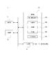
- FIG. 3 shows a functional configuration of the information processing apparatus 1 as the present embodiment.
- the information processing apparatus 1 includes an arithmetic unit 10, a communication unit 11, a storage unit 12, and an output unit 13.
- the communication unit 11 can transmit and receive data at least with the communication unit 35 of the imaging device 250 by wired or wireless communication.
- the information processing apparatus 1 can acquire the RED image data, the NIR image data, the first ambient light data, and the second ambient light data stored in the storage unit 34 of the imaging device 250 by the communication by the communication unit 11.
- wireless communication may be sequentially performed during imaging of the imaging device 250, and these data may be received and acquired, or data of each time point may be received and acquired collectively after the end of imaging.
- the storage unit 12 stores RED image data, NIR image data, first ambient light data, and second ambient light data acquired by the communication unit 11. If a memory card slot or the like is provided and a drive having a storage medium in common with the imaging device 250 is provided, the storage medium such as a memory card used in the imaging device 250 may function as the storage unit 12 as it is. Data may be transferred and stored from the storage medium to the storage medium (storage unit 12) inside the information processing apparatus 1.
- the calculation unit 10 is configured by a CPU 51 described later with reference to FIG.
- a vegetation index calculation unit 10A, a ratio calculation unit 10B, an extraction unit 10C, a generation unit 10D, and an output control unit 10E are provided as functional units to be executed by a program activated in the calculation unit 10 (CPU 51).
- the ratio calculation unit 10B calculates the ratio information that is the component ratio of the environmental light using the detection value at the corresponding time point, corresponding to the vegetation data (NDVI) for each time point.
- the component ratio of ambient light is the ratio of components contained (resolvable) in ambient light (for example, the ratio of the illuminance of each component).
- detection values include R, G, B, and IR detection values E-RED, E-GREEN, E-BLUE, and E-NIR.
- G detection value E-GREEN can be used to calculate ratio information. Conceivable.
- Ratio information (G detection value E-GREEN of direct light (or total skylight) / (G detection value E-GREEN of scattered light) It is possible to do.
- the illuminance is determined using the value of detected value (E-RED) + (E-GREEN) + (E-BLUE),
- Ratio information (illumination of direct light (or total skylight)) / (illumination of scattered light) It may be The ratio information calculated by these methods is stored in the storage unit 12 in association with the NDVI of the date / time / position.
- NDVI at each time point can be vegetation change information indicating changes in time-series NDVI, if not all of the NDVI extracted in particular, but if all of them are arranged. In that case, however, there are also cases where NDVI has become a value that is not very appropriate for time-series observation due to the influence of weather. In the present embodiment, an appropriate NDVI is extracted as time-series observation, and vegetation change information is thereby created.
- the generation unit 10D generates vegetation change information indicating a change in vegetation state in time series, using the data of the NDVI extracted by the extraction unit 10C. That is, the extracted NDVIs are arranged in time series to generate information capable of observing changes in vegetation.
- the output control unit 10E performs output control of the vegetation change information generated by the generation unit 10D. Specifically, processing of storing vegetation change information of a certain period in the storage unit 12 or supplying the output unit 13 for output is performed.
- the output unit 13 outputs the vegetation change information IFT generated by the calculation unit 10.
- the output unit 13 is a display output unit, supplies the vegetation change information IFT converted into image data to the display device, and is displayed and output.
- the output unit 13 is a print control unit, which supplies vegetation change information IFT as printing information to a printer device, and is printed out.
- the output unit 13 is an external device communication unit, and transmits the vegetation change information IFT to the external device.
- an arithmetic unit 10 (or an information processing apparatus having the arithmetic unit 10 is provided by providing at least a function as the extraction unit 10C by hardware or software. 1) corresponds to the information processing apparatus in claims.
- the information processing apparatus 1 can be realized as a personal computer (PC) or a field-programmable gate array (FPGA).
- the vegetation index calculator 10A and the ratio calculator 10B are provided on the information processing apparatus 1 side, but these are provided in the controller 33 of the imaging device 250, and NDVI and ratio information can be associated. It may be transmitted from the imaging device 250 to the information processing device 1 in the above state. Furthermore, the function as the extraction unit 10C and the generation unit 10D may be provided in the control unit 33 of the imaging device 250 so that the vegetation change information IFT can be output by the imaging device 250. In that case, the imaging device 250 corresponds to the information processing device described in the claims.
- the computer device 150 is configured to include a central processing unit (CPU) 51, a read only memory (ROM) 52, and a random access memory (RAM) 53.
- the CPU 51 executes various processes in accordance with a program stored in the ROM 52 or a program loaded from the storage unit 59 into the RAM 53.
- the RAM 53 also stores data necessary for the CPU 51 to execute various processes.
- the CPU 51, the ROM 52, and the RAM 53 are mutually connected via a bus 54.
- An input / output interface 55 is also connected to the bus 54.
- the input / output interface 55 includes a display 56 including a liquid crystal panel or an organic EL (Electroluminescence) panel, an input unit 56 including a keyboard, a mouse, etc., a speaker 58, a storage unit 59 including an HDD (Hard Disk Drive), etc.
- the communication unit 60 and the like can be connected.
- the display 56 may be integral with or separate from the computer device 150. For example, display of a captured image or a composite image, display of an evaluation index, and the like are performed.
- the input unit 57 means an input device used by a user who uses the computer device 150.
- the communication unit 60 performs communication processing via a network including the Internet, and communication with devices in peripheral units.
- the drive 61 is also connected to the input / output interface 55 as required, the memory card 62 is mounted, and a computer program read from the memory card 62 is installed in the storage unit 59 as needed, or the CPU 51 The data processed by are stored.
- the drive 61 may be a recording and reproduction drive for removable storage media such as a magnetic disk, an optical disk, and a magneto-optical disk.
- the processing as the information processing apparatus 1 of the embodiment that is, the processing as the extraction unit 10C and the generation unit 10D, or as the vegetation index calculation unit 10A, the ratio calculation unit 10B, and the output control unit 10E.
- Processing can be performed. That is, these processes are realized by software activated by the CPU 51.
- the programs constituting the software are downloaded from a network or read out from a removable storage medium and installed in the computer device 150 of FIG. Alternatively, the program may be stored in advance in an HDD as the storage unit 59 or the like. Then, when the program is activated in the CPU 51, the functions of the above-described units are expressed.
- FIG. 5 shows NDVI and PPFD observed in a certain period (here, a period from November 2 to November 30).
- the horizontal axis is the date
- the vertical axis is the value of NDVI and the value of PPFD.
- the broken line is NDVI and the solid line is PPFD.
- ⁇ white circle
- ⁇ black circle
- NDVI is directly correlated with PPFD (or illuminance) here
- NDVI measured outdoors is susceptible to the influence of the ambient light and fluctuates when the weather is different. It is a factor.
- the ratio of detection values by the sun sensor and the shade sensor is a value corresponding to the weather to a certain extent. Therefore, in the present embodiment, the ratio information is generated as described above, and the value of the NDVI suitable for time-series observation is extracted based on the ratio information. In other words, it is an idea to exclude the sample which varies depending on the weather condition.
- process 3 a plurality of pieces of ratio information close to one another are extracted. In this case, for example, NDVI data on November 6, 7 and 13 is finally extracted.
- FIGS. 7A and 7B show the finally extracted November 6, 7 and 13 NDVI data.
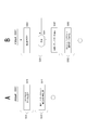
- FIG. 8 shows the case where extraction processing is not performed for comparison.
- FIG. 8A shows an NDVI data group associated with ratio information from November 5 to November 27. Vegetation change information generated using all the NDVI data without extraction by ratio information is shown in FIG. 8B. As can be seen from the figure, the variation in the value of NDVI is large, making it difficult to observe the state of the NDVI change in a period.
- FIG. 9 shows the case where extraction processing is performed.
- FIG. 9A is the same NDVI data group as FIG. 8A.
- the ratio information and the NDVI extracted by performing the above-described processing 1, processing 2, and processing 3 are hatched.
- the vegetation change information generated by the extracted NDVI data is shown in FIG. 9B.
- the variation which seems to be the influence of the weather condition is eliminated, and the vegetation change in the corresponding period is easy to observe.
- the processes a and b are the same as the processes 1 and 2 described above.
- process c the following conversion is performed.
- the value of NDVI to be extracted is shown in FIG. 10B (value before conversion to NDVI).
- a correlation is recognized between the value of the NDVI before conversion and the value of the ratio information, and linear approximation is possible. It is assumed that the slope of the approximate straight line L1 is ⁇ 0.0173.
- the ratio information is distributed within the range of 3.00 to 5.00, but this is converted to a constant value.
- 4.0 is an example.
- the constant value may be determined arbitrarily. For example, the average value, median value, centroid value, etc. of the extracted ratio information of NDVI may be used.
- the conversion in the first half of the period (November 5 to November 13) is by the linear approximation in FIG. 10B, but the conversion in the second half of the period (November 14 to November 27) is By a different linear approximation.
- the value of NDVI in the second half of the period is higher than that in the first half of the period, and the approximate straight line of those values is the approximate straight line L2 shown in FIG. If the slope of the approximate straight line L2 is the same as the slope of the approximate straight line L1, the value of the NDVI conversion value determined by the above equation can be obtained.
- FIG. 13A, 13B, and 13C are all processing performed by the calculation unit 10, and in particular, FIG. 13A is NDVI calculation processing performed by the vegetation index calculation unit 10A, and FIG. 13B is performed by the ratio calculation unit 10B.
- the ambient light component ratio (ratio information) calculation process, FIG. 13C can be said to be an example of the extraction / generation process performed by the extraction unit 10C, the generation unit 10D, and the output control unit 10E.
- step S ⁇ b> 100 the calculation unit 10 acquires the image data provided from the imaging device 250 and stores the image data in the storage unit 12. That is, RED image data and NIR image data are acquired and stored.
- step S101 the calculation unit 10 acquires ambient light data provided from the ambient light sensors 260A and 260B via the imaging device 250, and stores the ambient light data in the storage unit 12.
- detected values of R, G, B, IR of all skylight E-RED, E-GREEN, E-BLUE, E-NIR
- scattered light R, G, B, IR
- the detected values of (E-RED, E-GREEN, E-BLUE, E-NIR) are taken.
- all skylight detection values E-RED and E-NIR are used.
- Arithmetic unit 10 may execute the above NDVI arithmetic processing each time image data and ambient light data at each point of time are received, or image data and ambient light data for a certain period may be received together, or At the stage of storage in the storage unit 12, execution may be performed for each time point.
- step S200 the operation unit 10 acquires ambient light data provided from the ambient light sensor 260A via the imaging device 250, and stores the ambient light data in the storage unit 12. Note that this process can actually be executed in the same routine as step S101 in FIG. 13A.
- each detection value (E-RED, E-GREEN, E-BLUE) of R, G, B of all skylights is acquired and stored.
- step S201 the calculation unit 10 acquires ambient light data provided from the ambient light sensor 260B via the imaging device 250, and stores the ambient light data in the storage unit 12. That is, for calculation of ratio information, each detection value (E-RED, E-GREEN, E-BLUE) of R, G, B of scattered light is acquired and stored.
- each detection value E-RED, E-GREEN, E-BLUE
- step S202 the calculation unit 10 calculates ratio information.
- Ratio information (LA-LB) / LB Ask as. In other words, direct light / scattered light.
- ratio information LA / LB. In other words, it is all skylight / scattered light.
- the ratio information may be determined only by the detection value of G.
- step S300 the calculation unit 10 links the NDVI data generated in the process of FIG. 13A with the ambient light component ratio data (ratio information) generated in the process of FIG. 13B. That is, as shown in FIG. 8A, a data group in which NDVI at each time point and ratio information are associated with each other is formed. Then, the calculation unit 10 performs an NDVI extraction process for generating vegetation change information in step S301, and performs a vegetation change information generation process in step S302.
- step S303 the generated vegetation change information (for example, the information in FIG. 9B and FIG. 11B) is stored in the storage unit 12 and a process of controlling the output by the output unit 13 is performed.
- threshold value th1 0.5
- step S 351 the calculation unit 10 extracts NDVI data in which the ratio information has a value sufficiently larger than 0 as a candidate (processing 2).
- a provisional group is generated based on each NDVI data.
- the temporary groups all or part of the temporary groups having a plurality (or more than a predetermined number) of data numbers are respectively set as a group of a plurality of NDVI data close in ratio information.
- it may be considered to set a temporary group having the largest number of data or n temporary groups in the descending order of the number of data as a group of a plurality of NDVI data close in ratio information.
- each NDVI data contained in those groups is finally extracted.
- the extraction as described in FIG. 7B and FIG. 9A is performed.
- step S353 the operation unit 10 generates vegetation change information using the finally extracted plurality of NDVI data. For example, vegetation change information as shown in FIG. 9B is generated.
- ratio information total sky light
- scattered light data in the vicinity of the ambient light component ratio 1 is excluded in the process 1 described above.
- the threshold value th11 1.5 and the NDVI data for which the ratio information ⁇ th11 is excluded.
- FIG. 14B is an example of performing extraction and conversion by the above-described (Process a) (Process b) (Process c).
- step S351 the calculation unit 10 extracts NDVI data having ratio information that is sufficiently larger than 0 as a candidate (processing b).
- step S360 the operation unit 10 obtains an approximate expression from the correlation between the plurality of NDVI data extracted as candidates and the ratio information, and converts the ambient light component ratio to a constant value.
- the converted value of NDVI as shown in FIG. 11A can be obtained.
- the calculation unit 10 generates vegetation change information using the plurality of finally extracted NDVI data (converted values). For example, vegetation change information as shown in FIG. 11B is generated.
- step S371 the calculation unit 10 generates vegetation change information using the extracted NDVI data. That is, in the case of this example, only the NDVI observed in cloudy weather is extracted, and the vegetation change information capable of observing the NDVI can be generated. Depending on the plant type, area, climatic conditions, soil conditions, seasons and other environmental conditions, it may be possible to generate vegetation change information suitable for time-series observation by using only observation data in cloudy weather.
- FIG. 15B is an example in which it is possible to variably set how extraction processing conditions are to be set.
- the calculation unit 10 sets extraction conditions. For example, the user performs input processing using the input unit 57 of FIG. 4 to set under what conditions the extraction processing is to be performed. For example, the user can select the extraction process of FIG. 14A, the extraction process of FIG. 14B, the extraction process of FIG. 15A, and the like.
- the operation unit 10 proceeds from step S381 to S382, and extracts the NDVI data according to the set extraction condition.
- the NDVI data is extracted by any of the extraction process of FIG. 14A, the extraction process of FIG. 14B, and the extraction process of FIG. 15A.
- vegetation change information is generated using the extracted NDVI data.
- the operation unit 10 determines the type and nature of the plant from the captured image, for example, and the extraction process is set according to the determination result, instead of the user specifying the condition of the extraction process. .
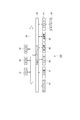
- FIGS. 16B and 16C show the ambient light sensor 260A that measures all skylight and the ambient light sensor 260B that measures scattered light.
- the sensor box SB is a unit of a case body including the ambient light sensor 260 and other devices.
- the light receiving unit 261 is provided on the upper surface of the sensor box SB.
- a pole-shaped light shield 262 is provided on the side of the ambient light sensor 260B as in the example of FIG. 1 described above.
- FIG. 16C is an example in which an arc-shaped light shielding body 262 is provided on the upper surface of the ambient light sensor 260B so as to cover the light receiving portion 261.
- FIGS. 16D and 16E show an example in which an ambient light sensor 260 for measuring all skylight and scattered light is mounted on one sensor box SB.
- the ambient light sensor 260 is provided with two light receiving portions 261A and 261B on the upper surface thereof, separated in the diagonal direction.
- FIG. 16D shows an example in which a bowl-shaped light shielding body 262 is provided on the side of one light receiving portion 261B. Scattered light is detected on the light receiving unit 261B side.
- FIG. 16E shows an example in which a pole-shaped light shielding body 262 is provided in the middle of a diagonal connecting the light receiving portions 261A and 261B. Depending on the attitude direction of the flying object 200, the shadow of the light shielding body 262 is dropped to one of the light receiving portions 261A and 261B, and that detects the scattered light.
- the environment light sensor 260 often flies with the airframe at an angle.
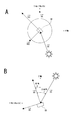
- the correction value of the direct light differs depending on the difference in the incident angle of the sunlight incident on the sensor box SB of the ambient light sensor 260 at that time. This situation is shown in FIG.
- FIG. 17A is a top view of the sensor box SB provided with the ambient light sensor 260, and the vector VA indicates the flight direction. This figure shows an example in which the vehicle is heading north.
- FIG. 17B is a view of the sensor box SB as viewed from the side. Further, an IMU (inertial measurement device) is mounted on the sensor box SB. Two vectors (vector VB1, vector) forming the upper surface of the sensor box SB from the values of Roll, Pitch, and Yaw taken from the IMU (inertial measurement device) mounted on the sensor box SB Extract VB2). By taking the outer product of these two vectors, a vector VH (normal vector on the upper surface of the sensor box SB shown in FIG. 17B) orthogonal to these can be obtained. Moreover, sunlight is extracted as a vector VS (see FIG. 17B) from the azimuth and the altitude.
- vector VS normal vector on the upper surface of the sensor box SB shown in FIG. 17B
- the illuminance value (LA) of total skylight and the illuminance value (LB) of scattered light are obtained.
- direct light (LC) to the ambient light sensor 260 is calculated.
- Direct delivery light LC LA-LB.
- the upper surface of the sensor box SB is inclined by the elevation angle ⁇ , and correction is performed in consideration of that.
- the elevation angle ⁇ is obtained by the following (Equation 2).
- the illuminance when illuminating a surface at a certain distance from the light source is the brightest when the surface is perpendicular to the light traveling direction, and becomes dark when the surface is inclined. That is, the illuminance has the property of changing in proportion to the cosine (COS ( ⁇ )) of the incident angle ⁇ of light incident on the surface. That is, it is an oblique incident light characteristic (cosine characteristic) of illuminance.
- COS ( ⁇ ) cosine
- the flying attitude of the flying object 200 causes a detection error of direct light (all sky light). Therefore, it is preferable to obtain the direct light by performing correction in consideration of such cosine characteristics.
- FIG. 18 shows an example of a flight plan of the flying object 200 for reliably detecting scattered light.
- the flying object 200 flying in the field 210 for the purpose of calculating the vegetation index flies in the direction DA shown in the drawing, and repeats the action of flying in the direction DB in a U-turn or reverse flight at the break of the field 210.
- the direction change is performed by one rotation and half rotation in the hovering state.
- the solid line indicates the traveling direction of the flying object 200
- the broken arrow HC indicates the operation of one half rotation of the flying object 200
- the dashed arrow CC indicates the movement of the flying object 200 one revolution.
- the flying object 200 will make one rotation successively.
- the control unit provided in the flying object 200 or the imaging device 250 or the ambient light sensor 260 determines the minimum one of the illuminances acquired while rotating 360 degrees as the illuminance value of the scattered light. Then, the illuminance value is made to correspond to the captured image data as a detection value of scattered light in the current flight. By doing this, the scattered light can be accurately detected using the ambient light sensor 260 provided with the light shielding body 262.
- the example which does not perform such 360 degree rotation is also considered.
- the light shield 262 is installed automatically or manually so that the light receiving portion 261 of the ambient light sensor 260 is shaded, or the posture direction of the sensor box SB is It is also conceivable to make it change automatically or manually.
- FIG. 19A shows a sensor box SB mounted on the flying object 200
- FIG. 19B shows a sensor box SBg having an ambient light sensor 260 installed on the ground, for example
- FIG. 19C shows the configuration in the sensor boxes SB and SBg and the signal processing unit 310.
- an ambient light sensor 260, an IMU 272, and a control unit 273 are incorporated in the sensor box SB mounted on the flying object 200.
- An ambient light sensor 260 and a control unit 373 are built in the sensor box SBg installed on the ground.
- the detection value of the ambient light sensor 260 and the attitude information (IMU values: Roll, Pitch, Yaw) of the sensor box SB synchronized with the timing at which the detection value is acquired are required. . Therefore, the control unit 273 simultaneously accesses the IMU 272 at the timing of accessing the ambient light sensor 260, and acquires the detected value and the attitude information.
- the acquired data is sent to the signal processing unit 310 directly or indirectly, and calculation of corrected direct transmitted light using the incident angle ⁇ and the elevation angle ⁇ described above is performed.
- the signal processing unit 310 can be realized by an FPGA or an external PC. This process can also upload detection values and attitude information to the cloud computing system for execution.
- the detection value of total sky light and scattered light is periodically acquired by the sensor box SBg installed on the ground, and the control unit 373 sends it to the signal processing unit 310.
- Information of detection date and time is added to this detection value, and the detection value is compared with a time stamp when the imaging device 250 captures an image, so that the detection value of the environmental light sensor 260 at a timing when acquisition is difficult in the sky. Acquisition can be interpolated.
- the information processing apparatus 1 uses ratio information with respect to a data group having vegetation data (for example, NDVI data) at a plurality of points in time in which ratio information which is a component ratio of environmental light is associated with each other. It has an extraction unit 10C that extracts vegetation data.
- the information processing apparatus 1 according to the embodiment also includes a generation unit 10D that generates vegetation change information indicating a change in vegetation state in time series, using the vegetation data extracted by the extraction unit 10C.
- the vegetation data at each time point and the data group in which the ratio information at the time of observation is associated are treated as the processing target, and the vegetation data (NDVI data) suitable for output is extracted by the ratio information.
- vegetation change information is generated using the extracted vegetation data.
- the value of vegetation data such as NDVI may vary greatly due to the influence of environmental light, it is possible to generate vegetation change information by extracting only data suitable for the purpose of showing a time-series transition based on ratio information. That is, in a situation where values are dispersed due to the influence of the weather, etc., the vegetation data whose value fluctuates due to the influence of the weather is eliminated to generate vegetation change information that accurately presents the change of vegetation in time series. It is very useful for vegetation observation.
- the ratio information is the value of the ratio of each detection value of direct light to scattered light, or the value of the ratio of each detection of total sky light and scattered light.
- the light sensor disposed at the sun position so that direct light can be received when the weather is fine
- direct light and scattered light can be received, so that the amount of total skylight can be detected.
- the amount of scattered light can be detected depending on the light sensor disposed at the shade position so that the scattered light can be received at the time of fine weather.
- the light amount of direct light is obtained by subtracting the light amount of scattered light from the light amount of all skylights.
- the direct light is almost zero, and the scattered light ⁇ total sky light.
- the value of the ratio of the detection value of the direct light to the detection value of the scattered light is approximately "0" at the time of cloudy weather or rainy weather.
- the value of the ratio of total sky light to scattered light is approximately "1" at cloudy weather or rainy weather. That is, the ratio information has a value corresponding to the weather.
- the ratio information has a value corresponding to the weather.
- the extraction unit 10C excludes from vegetation data using vegetation data in which the value of the associated ratio information is determined to be near a specific value (for example, around 0 or around 1) by comparison with the threshold th1.
- a specific value for example, around 0 or around 1
- FIG. 14A, S350 in FIG. 14B An example was described (FIG. 14A, S350 in FIG. 14B).
- vegetation data can be extracted such that vegetation data observed in the absence of direct sunlight, such as cloudy weather (including wet weather), is eliminated. This makes it possible to generate vegetation change information in which the influence of weather is reduced.
- the extraction unit 10C performs a process of extracting a plurality of vegetation data in which the values of the associated ratio information are determined to be close to each other by comparison with the threshold value th2 (see FIG. 14A S352).
- the fact that the ratio information, which is the component ratio of the environmental light, is close means that the state of the environmental light at the time of observation for vegetation data calculation is similar. Therefore, it can be said that a plurality of vegetation data having similar ratio information are samples at different points in time and in which the state of environmental light at the time of observation is similar. This makes it possible to collect vegetation data close to environmental light conditions, and is suitable for generating vegetation change information in which the influence of weather is reduced.
- the extraction unit 10C describes an example of performing processing for extracting vegetation data in which the value of the associated ratio information is determined to be near a specific value by comparison with the threshold value th1 (S370 in FIG. 15A). .
- the ratio information is “0" or “1” at cloudy weather
- these "0" or “1” are specified values and the ratio information is a value near the specified value.
- a specific environmental light state for example, cloudy weather. This makes it possible to collect vegetation data close to environmental light conditions, which is also suitable for generating vegetation change information with reduced influence of weather.
- the extraction condition of the extraction process by the extraction unit 10C can be variably set (FIG. 15B). This makes it possible to select various conditions and extract vegetation data to be used. For example, if the extraction condition is variably set by the user operation, the user can extract an arbitrary weather condition and generate vegetation change information.
- the generation unit 10D converts vegetation data extracted by the extraction unit 10C into a value when the ratio information is constant, and generates vegetation change information using the converted vegetation data. (S360, S353 in FIG. 14B). This makes it possible to generate vegetation change information that is less susceptible to fluctuations due to environmental light. The conversion can be made with high accuracy by using an approximate expression.
- the information processing apparatus 1 includes the vegetation data calculation unit 10A that calculates vegetation data using observation data (for example, captured image data) of vegetation at each time point (see FIG. 3).
- vegetation data such as NDVI data
- the vegetation data calculation unit 10A is an example of obtaining the value of NDVI as the vegetation data.
- NDVI is an indicator showing the distribution status and activity of vegetation. Generating vegetation change information as information indicating time-series changes in NDVI is useful for observing changes in vegetation conditions.
- the information processing apparatus 1 calculates the ratio information which is the component ratio of the environmental light using the detection value of the environmental light corresponding to the vegetation data at each time.
- the example provided with the calculating part 10B was described (refer FIG. 3).
- the processing of the extraction unit and the generation unit becomes possible by acquiring the detection value of the ambient light sensor 260. Therefore, no burden is particularly imposed on the side of the observation apparatus using the flying object 200 or the like.
- the ratio calculation unit 10B can be obtained by the ambient light sensor 260 including the light receiving unit 261 that becomes a shade by the light shielding body 262 and the light receiving unit 261 that is not influenced by the light shielding body 262.
- An example in which ratio information is calculated using the detected values of (1) and (2) is described (see FIGS. 2 and 16).
- the structure having the light shielding body 260 detection of direct light and scattered light is accurately performed using the ambient light sensor 260 mounted on the flying object 200. Therefore, in the information processing apparatus 1, the accuracy of the ratio information can be made high, and appropriate vegetation data can be extracted.
- NDVI was mentioned as an example of vegetation data
- the vegetation index used as vegetation data can be variously considered.
- PRI photochemical reflectance index
- PRI is an index of the spectral reflectance that changes with the deepoxidation of the xanthophyll cycle.
- the xanthophyll cycle is a mechanism that releases excess light energy that can not be photosynthesized, such as intense light or pore blockage associated with water stress, as heat.
- the magnitude of chlorophyll fluorescence may be the magnitude of chlorophyll fluorescence excited by sunlight (solar-induced chlorophyll fluorescence (SIF)), or chlorophyll fluorescence may be excited using a laser or LED instead of sunlight .
- the chlorophyll fluorescence index is measured by dividing chlorophyll fluorescence into several wavelengths, and is represented by, for example, a ratio of two wavelengths of 685 nm and 735 nm. Chlorophyll fluorescence can also be used for stress detection.
- Chlorophyll fluorescence is fluorescence emitted from plants with photosynthesis of plants, and energy is emitted as fluorescence with a wavelength of around 680 nm to 770 nm in higher plants if energy is not extracted from the reaction center where electrons are excited by light within a certain period of time Phenomenon.
- the energy released is 0.5% to 3% of the energy of input light and fluctuates according to the photosynthetic state of plants, and excessive light energy that can not be photosynthesized, such as strong light or pore blockage caused by water stress When there are many, it becomes large.
- the observation target is the vegetation of the field 210
- the present technology can be applied to vegetation observation of grass in sports grounds such as soccer fields and baseball grounds, vegetation observation of natural grasslands, forest fields, virgin forests and the like.
- the computing unit 10 may be mounted on the aircraft 200.
- a microcomputer in the imaging device 250 may function as the arithmetic unit 10.
- a microcomputer may be mounted in the sensor box SB including the ambient light sensor 260 and function as the calculation unit 10.
- the ambient light sensor 260 may detect all sky light and scattered light only by the environment light sensor 260 installed on the ground without using the one mounted on the flying object 200.
- Such a program facilitates the implementation of the information processing apparatus 1 of the present embodiment.
- a program can be stored in advance in a recording medium incorporated in an apparatus such as a computer device, a ROM in a microcomputer having a CPU, or the like.
- it can be stored (stored) temporarily or permanently in a removable recording medium such as a semiconductor memory, a memory card, an optical disk, a magneto-optical disk, or a magnetic disk.
- a removable recording media can be provided as so-called package software.
- such a program can be installed from a removable recording medium to a personal computer or the like, and can also be downloaded from a download site via a network such as a LAN or the Internet.
- An information processing apparatus comprising: an extraction unit configured to extract at least a part of vegetation data based on the ratio information from vegetation data at a plurality of points in time at which ratio information which is a component ratio of environmental light is associated with each other.
- the information processing apparatus according to (1) further including: a generation unit configured to generate vegetation change information indicating a change in the vegetation data in time series using the vegetation data extracted by the extraction unit.
- the ratio information is a value of a ratio of a detection value of direct light to a detection value of scattered light, or a value of a ratio of a detection value of total sky light to a detection value of scattered light described in the above (1) or (2) Information processing equipment.
- the extraction unit performs a process of excluding vegetation data in which the value of the associated ratio information is determined to be near a specific value by comparison with a threshold, from the vegetation data to be used any of the above (1) to (3) Information processing apparatus described in. (5) The extraction unit performs processing for extracting vegetation data in which the value of the associated ratio information has a difference of a predetermined value or more with respect to a specific value according to any one of (1) to (4). Information processing equipment. (6) The extraction unit performs a process of extracting a plurality of vegetation data which are determined to be close to each other by comparing the value of the associated ratio information with a threshold value. Information processor as described.
- the extraction unit performs a process of extracting vegetation data in which the value of the associated ratio information is determined to be near a specific value by comparison with a threshold value.
- the generation unit converts the vegetation data extracted by the extraction unit into a value when the ratio information is constant, and generates vegetation change information using the converted vegetation data. apparatus.
- the information processing apparatus obtains a value of NDVI as vegetation data.
- a ratio calculator configured to calculate ratio information, which is a component ratio of environmental light, using the detected value of environmental light at the corresponding time according to the vegetation data for each time, any one of the above (1) to (11) Information processing apparatus described in. (13) The ratio calculating unit The ratio information is calculated using the detection value of each light receiving unit obtained by an environmental light sensor having a light receiving unit that is shaded by the light blocking unit and a light receiving unit that is not affected by the light blocking unit. Processing unit.
- An ambient light sensor having a light receiving portion that is shaded by a light blocking body and a light receiving portion that is not affected by the light blocking body;
- a ratio calculation unit that calculates ratio information, which is a component ratio of environmental light, using the detection value of each light receiving unit at a corresponding time point, corresponding to the vegetation data for each time point;
- An extraction unit for extracting vegetation data to be used using ratio information, with respect to a data group having vegetation data at a plurality of points in time, each being associated with ratio information that is a component ratio of environmental light;
- An information processing system comprising: a generation unit configured to generate vegetation change information indicating a change in vegetation state in time series using the vegetation data extracted by the extraction unit.
Abstract
時系列的な植生状態の変化を適切に表す植生変化情報が生成できるようにする。このために、それぞれに環境光の成分比である比情報が対応づけられた複数の時点の植生データを有するデータ群を処理対象とする。このデータ群について、比情報を用いて使用する植生データの抽出を行う抽出部と、抽出部で抽出された植生データを用いて、時系列での植生状態の変化を示す植生変化情報を生成する生成部とを備えるようにする。比情報を用いることで環境光条件が似通った植生データを集めることができる。
Description
本技術は情報処理装置、情報処理方法、プログラム、情報処理システムに関し、特に植生状態の変化を提示する植生変化情報の生成に好適な技術に関する。
例えば小型の飛行体に撮像装置を搭載し、圃場の上空を移動しながら植物の植生状態を撮像していくことで、植生状態をリモートセンシングする取り組みがある。
特許文献1には、圃場を撮像し、リモートセンシングを行う技術に関して開示されている。
特許文献1には、圃場を撮像し、リモートセンシングを行う技術に関して開示されている。
圃場の植生の撮像画像からは植生指数を測定することができ、例えば日ごとに撮像された画像から植生指数を求めていけば、時系列的な植生状態の変化を提示する植生変化情報を生成することができる。例えば植生指数としてNDVI(Normalized Difference Vegetation Index)を求め、時系列に並べることで、植生状態の変化が確認できる。
ところがNDVI等の植生指数については、天候(晴天/曇天)などの条件の違いにより値が変動するということが生じていた。すると、例えば日ごとのNDVIの変化を確認したいと思っても、NDVIを時系列に並べた植生変化情報には、天候による値の変動が含まれていることになる。このため作業者等は植生変化情報を見ても、日ごとの植生の変化を正しくつかめない。
そこで本技術では、天候等の条件による変動を受けにくい植生変化情報を生成できるようにし、時系列的な植生状態の変化を的確に提示できるようにすることを目的とする。
ところがNDVI等の植生指数については、天候(晴天/曇天)などの条件の違いにより値が変動するということが生じていた。すると、例えば日ごとのNDVIの変化を確認したいと思っても、NDVIを時系列に並べた植生変化情報には、天候による値の変動が含まれていることになる。このため作業者等は植生変化情報を見ても、日ごとの植生の変化を正しくつかめない。
そこで本技術では、天候等の条件による変動を受けにくい植生変化情報を生成できるようにし、時系列的な植生状態の変化を的確に提示できるようにすることを目的とする。
本技術に係る情報処理装置は、それぞれに環境光の成分比である比情報が対応づけられた複数の時点の植生データから、前記比情報に基づいて少なくとも一部の植生データを抽出する抽出部を備えている。
即ち各時点の植生データを有するとともに、その観測時の環境光の成分比(比情報)が対応づけられているデータ群を処理対象とする。この場合に、比情報により、出力に適した植生データを抽出する。
また上記した情報処理装置においては、前記抽出部で抽出された植生データを用いて、時系列での前記植生データの変化を示す植生変化情報を生成する生成部を備えている。
即ち比情報により抽出部で抽出した、出力に適した植生データを用いて植生変化情報を生成する。
即ち各時点の植生データを有するとともに、その観測時の環境光の成分比(比情報)が対応づけられているデータ群を処理対象とする。この場合に、比情報により、出力に適した植生データを抽出する。
また上記した情報処理装置においては、前記抽出部で抽出された植生データを用いて、時系列での前記植生データの変化を示す植生変化情報を生成する生成部を備えている。
即ち比情報により抽出部で抽出した、出力に適した植生データを用いて植生変化情報を生成する。
上記した情報処理装置においては、前記比情報は、直達光の検出値と散乱光の検出値の比の値、又は全天光の検出値と散乱光の検出値の比の値であることが考えられる。
直達光は例えば太陽等の高原から直接到達した光成分(いわゆる直射日光)であり、散乱光は大気の分子や雲粒で散乱された光である。直達光と散乱光の和が全天光となる。
直達光は例えば太陽等の高原から直接到達した光成分(いわゆる直射日光)であり、散乱光は大気の分子や雲粒で散乱された光である。直達光と散乱光の和が全天光となる。
上記した情報処理装置においては、前記抽出部は、対応づけられた比情報の値が閾値との比較により特定値付近と判定される植生データを、使用する植生データから排除する処理を行うことが考えられる。
例えば比情報を(直達光)/(散乱光)とした場合、曇天時は比情報=0付近となる。
また例えば比情報を(全天光)/(散乱光)とした場合、曇天時は比情報=1付近となる。これらの“0”或いは“1”を特定値とし、比情報が特定値もしくは特定値に近い値となっている植生データを排除する。
例えば比情報を(直達光)/(散乱光)とした場合、曇天時は比情報=0付近となる。
また例えば比情報を(全天光)/(散乱光)とした場合、曇天時は比情報=1付近となる。これらの“0”或いは“1”を特定値とし、比情報が特定値もしくは特定値に近い値となっている植生データを排除する。
上記した情報処理装置においては、前記抽出部は、対応づけられた比情報の値が、特定値に対して所定以上の差を有している植生データを抽出する処理を行うことが考えられる。
例えば曇天時に比情報が“0”或いは“1”となるように比情報を計算する場合において、これらの“0”或いは“1”を特定値とし、比情報が特定値から十分に離れている値となっている植生データを使用する植生データ(もしくはその候補)として抽出する。
例えば曇天時に比情報が“0”或いは“1”となるように比情報を計算する場合において、これらの“0”或いは“1”を特定値とし、比情報が特定値から十分に離れている値となっている植生データを使用する植生データ(もしくはその候補)として抽出する。
上記した情報処理装置においては、前記抽出部は、対応づけられた比情報の値が閾値との比較により互いに近接していると判定される複数の植生データを抽出する処理を行うことが考えられる。
環境光の成分比である比情報が近接しているということは、植生データ算出のための観測時の環境光の状態が類似しているということである。
環境光の成分比である比情報が近接しているということは、植生データ算出のための観測時の環境光の状態が類似しているということである。
上記した情報処理装置においては、前記抽出部は、対応づけられた比情報の値が閾値との比較により特定値付近と判定される植生データを抽出する処理を行うことが考えられる。
例えば曇天時に比情報が“0”或いは“1”となるように比情報を計算する場合において、これらの“0”或いは“1”を特定値とし、比情報が特定値付近の値となっている植生データを使用する植生データ(もしくはその候補)として抽出する。
例えば曇天時に比情報が“0”或いは“1”となるように比情報を計算する場合において、これらの“0”或いは“1”を特定値とし、比情報が特定値付近の値となっている植生データを使用する植生データ(もしくはその候補)として抽出する。
上記した情報処理装置においては、前記抽出部による抽出処理の抽出条件が可変設定可能とされていることが考えられる。
例えば比情報が特定値に近い植生データの排除、比情報が特定値から十分離れている植生データの抽出、比情報が近い複数の植生データの抽出、比情報が特定値に近い植生データの抽出、等の抽出処理の条件を、ユーザ操作等により可変設定可能とする。
例えば比情報が特定値に近い植生データの排除、比情報が特定値から十分離れている植生データの抽出、比情報が近い複数の植生データの抽出、比情報が特定値に近い植生データの抽出、等の抽出処理の条件を、ユーザ操作等により可変設定可能とする。
上記した情報処理装置においては、前記生成部は、前記抽出部が抽出した植生データについて、比情報を一定としたときの値に換算し、換算した植生データを用いて植生変化情報を生成することが考えられる。
例えば抽出された比情報が近い植生データを用いて植生変化情報を生成することになるが、植生データを、比情報が一定値となる状態に換算する。
例えば抽出された比情報が近い植生データを用いて植生変化情報を生成することになるが、植生データを、比情報が一定値となる状態に換算する。
上記した情報処理装置においては、各時点についての植生の観測データを用いて植生データを算出する植生データ演算部を備えることが考えられる。
即ち各時点の植生データを情報処理装置内で生成するようにする。
即ち各時点の植生データを情報処理装置内で生成するようにする。
上記した情報処理装置においては、前記植生データ演算部は、植生データとしてNDVIの値を求めることが考えられる。
即ち植生指数であるNDVIの値を求め、このNDVIの変化としての植生変化情報が生成されるようにする。
即ち植生指数であるNDVIの値を求め、このNDVIの変化としての植生変化情報が生成されるようにする。
上記した情報処理装置においては、各時点についての植生データに対応して、該当時点の環境光の検出値を用いて環境光の成分比である比情報を算出する比演算部を備えることが考えられる。
即ち各時点の植生データに対応する比情報を情報処理装置内で生成するようにする。比情報は植生データの生成に用いた検出値と略同時点に得られた光検出値を用いて算出する。
即ち各時点の植生データに対応する比情報を情報処理装置内で生成するようにする。比情報は植生データの生成に用いた検出値と略同時点に得られた光検出値を用いて算出する。
上記した情報処理装置においては、前記比演算部は、
遮光体により日陰となる受光部と遮光体による影響を受けない受光部とを有する環境光センサにより得られる、各受光部の検出値を用いて比情報を算出することが考えられる。
遮光体により飛行体に搭載された環境光センサを用いて直達光、散乱光の検出が可能となる。
遮光体により日陰となる受光部と遮光体による影響を受けない受光部とを有する環境光センサにより得られる、各受光部の検出値を用いて比情報を算出することが考えられる。
遮光体により飛行体に搭載された環境光センサを用いて直達光、散乱光の検出が可能となる。
本技術に係る情報処理方法は、それぞれに環境光の成分比である比情報が対応づけられた複数の時点の植生データを有するデータ群について、比情報を用いて使用する植生データの抽出を行う処理を情報処理装置が実行する情報処理方法である。これにより情報処理装置において環境条件による影響を受けにくい植生変化情報を生成するための植生データ抽出ができる。
本技術に係るプログラムは、それぞれに環境光の成分比である比情報が対応づけられた複数の時点の植生データを有するデータ群について、比情報を用いて使用する植生データの抽出を行う処理をコンピュータ装置に実行させるプログラムである。これにより環境条件による影響を受けにくい植生変化情報を生成するための植生データ抽出を行うコンピュータ装置の実現が容易となる。
本技術に係る情報処理システムは、遮光体により日陰となる受光部と遮光体による影響を受けない受光部とを有する環境光センサと、上記の比演算部と、抽出部と、生成部とを備える。これにより環境条件による影響を受けにくい植生変化情報の生成に適したシステムを構築できる。
本技術によれば、天候等の条件による変動が表れにくく時系列的な植生状態の変化を的確に提示できる植生変化情報を生成できるという効果がある。
なお、ここに記載された効果は必ずしも限定されるものではなく、本開示中に記載されたいずれかの効果であってもよい。
なお、ここに記載された効果は必ずしも限定されるものではなく、本開示中に記載されたいずれかの効果であってもよい。
以下、実施の形態を次の順序で説明する。
<1.システム・装置の構成>
<2.比情報を用いた抽出処理>
<3.比情報を用いた植生指数の換算処理>
<4.処理例>
<5.環境光センサによる光検出に関する各種の例>
<6.まとめ及び変形例>
<1.システム・装置の構成>
<2.比情報を用いた抽出処理>
<3.比情報を用いた植生指数の換算処理>
<4.処理例>
<5.環境光センサによる光検出に関する各種の例>
<6.まとめ及び変形例>
<1.システム・装置の構成>
実施の形態では圃場の植生状態のセンシングを行う場合を例に挙げて説明する。
図1に示すように飛行体200に搭載された撮像装置250を用いて圃場210の植生に関するリモートセンシングを例えば毎日行う。そして、毎日の観測で得られた植生データ(例えば植生指数のデータ)を用いて情報処理装置1で時系列的な植生状態の変化を示す植生変化情報を生成するという例で説明する。
実施の形態では圃場の植生状態のセンシングを行う場合を例に挙げて説明する。
図1に示すように飛行体200に搭載された撮像装置250を用いて圃場210の植生に関するリモートセンシングを例えば毎日行う。そして、毎日の観測で得られた植生データ(例えば植生指数のデータ)を用いて情報処理装置1で時系列的な植生状態の変化を示す植生変化情報を生成するという例で説明する。
図1は圃場210の様子を示している。
小型の飛行体200は、例えば操作者の無線操縦、或いは無線自動操縦等により、圃場210の上空を移動することができる。
飛行体300には撮像装置250が例えば下方を撮像するようにセットされている。飛行体200が所定の経路で圃場210の上空を移動する際に、撮像装置250は例えば定期的に静止画撮像を行ったり、或いは動画撮像を行うことで、各時点において撮像視野の範囲Wの画像を得ることができる。
小型の飛行体200は、例えば操作者の無線操縦、或いは無線自動操縦等により、圃場210の上空を移動することができる。
飛行体300には撮像装置250が例えば下方を撮像するようにセットされている。飛行体200が所定の経路で圃場210の上空を移動する際に、撮像装置250は例えば定期的に静止画撮像を行ったり、或いは動画撮像を行うことで、各時点において撮像視野の範囲Wの画像を得ることができる。
撮像装置250がどのような種類の撮像装置であるかは各種考えられる。
例えば撮像装置250の撮像によって得られる画像ファイル(或る時点の撮像画像)には分光計測画像を含むことが考えられる。即ち撮像装置250はマルチスペクトラムカメラとされ、撮像される画像としては、特定の2以上の波長領域の情報を有する測定画像を含むものが考えられる。
また撮像装置250としてR(赤)、G(緑)、B(青)の可視光画像を撮像するカメラが用いられてもよい。
また撮像装置250として、赤波長領域(RED)と近赤外領域(NIR:Near Infra Red)の撮像画像を得るカメラであり、得られる画像からNDVIが算出できるものが用いられてもよい。NDVIとは植生の分布状況や活性度を示す指標である。
以下では撮像装置250は赤波長領域(RED)と近赤外領域(NIR)の撮像画像を得ることができるカメラであるとして説明する。
また撮像装置250で撮像されて得られる画像には、タグ情報が付加されている。タグ情報には撮像日時情報や、GPS(Global Positioning System)データとしての位置情報(緯度/経度情報)、撮像装置情報(カメラの個体識別情報や機種情報等)、各画像データの情報(画サイズ、波長、撮像パラメータ等の情報)などが含まれている。
本実施の形態では、飛行体200には撮像装置250とともに、環境光センサ260が搭載されている。図1の例では2つの環境光センサ260A、260Bが飛行体200の上面側に搭載されている。
なお、使用する1又は複数の環境光センサをまとめて指す場合は「環境光センサ260」と表記する。
なお、使用する1又は複数の環境光センサをまとめて指す場合は「環境光センサ260」と表記する。
環境光センサ260A、260Bのそれぞれは、上面側に受光部261を備えて光検出を行う。この構成により太陽400を光源とする環境光のレベル(照度、光合成光量子束密度(photosynthetic photon flux density:以下「PPFD」と記述)等)を検知することができる。
なおPPFDはクロロフィルが吸収できる400nmから700nmまでの波長領域だけの光量子束密度である。
なおPPFDはクロロフィルが吸収できる400nmから700nmまでの波長領域だけの光量子束密度である。
環境光センサ260A、260Bの検出値によって全天光、散乱光の光量を検出することができ、またこれらから直達光の光量を算出できる。
屋外における環境光は一般に、(全天光)=(直達光)+(散乱光)と表される。
直達光とは太陽400からのいわゆる直射日光を意味する。
散乱光とは直射日光以外にも大気の分子や雲粒で散乱された光である。
全天光とは全天からの光の総和であり、直達光と散乱光の和でもある。
屋外における環境光は一般に、(全天光)=(直達光)+(散乱光)と表される。
直達光とは太陽400からのいわゆる直射日光を意味する。
散乱光とは直射日光以外にも大気の分子や雲粒で散乱された光である。
全天光とは全天からの光の総和であり、直達光と散乱光の和でもある。
環境光センサ260Aには日光を遮るものは設けられておらず、このため環境光センサ260Aによっては直達光も散乱光も受光される。従って環境光センサ260Aによっては全天光の照度等が検出できる。
環境光センサ260Bには上面に突設されたポール状の遮光体262が設けられており、この遮光体262が受光部261に影SDWを落とす。これによって受光部261は直達光を受光しない。従って環境光センサ260Bによっては散乱光の照度等が検出される。
直達光については、環境光センサ260Aの検出値から環境光センサ260Bの検出値を減算することで求められる。
環境光センサ260Bには上面に突設されたポール状の遮光体262が設けられており、この遮光体262が受光部261に影SDWを落とす。これによって受光部261は直達光を受光しない。従って環境光センサ260Bによっては散乱光の照度等が検出される。
直達光については、環境光センサ260Aの検出値から環境光センサ260Bの検出値を減算することで求められる。
環境光センサ260A、260Bとしては、環境光としてR(赤),G(緑),B(青),NIR(近赤外光)の照度をそれぞれ出力するものが考えられる。
即ち環境光センサ260Aによっては全天光のR,G,B,IRの各検出値(E-RED、E-GREEN、E-BLUE、E-NIR)が得られ、環境光センサ260Bによっては散乱光のR,G,B,IRの各検出値(E-RED、E-GREEN、E-BLUE、E-NIR)がそれぞれ得られる。
即ち環境光センサ260Aによっては全天光のR,G,B,IRの各検出値(E-RED、E-GREEN、E-BLUE、E-NIR)が得られ、環境光センサ260Bによっては散乱光のR,G,B,IRの各検出値(E-RED、E-GREEN、E-BLUE、E-NIR)がそれぞれ得られる。
なお、環境光センサ260A、260Bによる検出値については、タグ情報が付加される。例えばタグ情報として検出日時情報や、GPSデータとしての位置情報(緯度/経度情報)などが含まれるようにする。
ところで、環境光センサ260Bにおいてポール状の遮光体262を設けるのは、なるべく受光部261に対して直射日光のみを遮光することが望ましいためである。換言すれば、受光部261に対して太陽400のみをピンポイントで覆うことがよい。これは広く遮光してしまうと、散乱光の一部も遮光されることになり、散乱光レベルの検出が正確でなくなったり、値がばらつくことがあるためである。
以上のように飛行体200に搭載された撮像装置250や環境光センサ260によって得られる画像データや検出値は、情報処理装置1に送られる。情報処理装置1は画像データや検出値を用いて時系列での植生状態の変化を示す植生変化情報を生成する。本実施の形態では、具体的には時系列でのNDVIの変化を示す植生変化情報を生成する例で説明するが、特に天気の影響によるNDVIの値の変動を抑えた状態の植生変化情報を提供できるようにするものである。
情報処理装置1は、例えばPC(personal computer)やFPGA(field-programmable gate array)などとして実現される。
なお、図1では情報処理装置1は撮像装置250とは別体のものとしているが、撮像装置250を含むユニット内に情報処理装置1となる演算装置(マイクロコンピュータ等)を設けてもよい。
情報処理装置1は、例えばPC(personal computer)やFPGA(field-programmable gate array)などとして実現される。
なお、図1では情報処理装置1は撮像装置250とは別体のものとしているが、撮像装置250を含むユニット内に情報処理装置1となる演算装置(マイクロコンピュータ等)を設けてもよい。
図2に撮像装置250の構成例を示す。
撮像装置250は、撮像部31、信号処理部32、制御部33、格納部34、通信部35、位置検出部36、時計部37を有する。
撮像装置250は、撮像部31、信号処理部32、制御部33、格納部34、通信部35、位置検出部36、時計部37を有する。
撮像部31は、撮像レンズ系、露光部、フィルタ、及びイメージセンサ等を有し、被写体光を受光して電気信号としての撮像画像信号を出力する。
即ち撮像部31において、被測定対象物等の被写体からの光(反射光)は、レンズ系とフィルタを介してイメージセンサに入射される。
レンズ系とは入射端レンズ、ズームレンズ、フォーカスレンズ、集光レンズなど各種レンズを含む入射光学系のことをいう。
フィルタとは被測定対象物についての測定しようとする波長を取り出すためのフィルタである。これは一般にイメージセンサ上に構成されるカラーフィルタとその前に配置される波長フィルタなどをいう。
露光部とは、イメージセンサにおいて、信号電荷が飽和せずにダイナミックレンジ内に入っている状態でセンシングが行われるように、レンズ系等の光学系やアイリス(絞り)による開口量などを調整することで、露光制御を行う部位をいう。
イメージセンサは、そのセンサ面に、複数の画素が繰り返しパターンで2次元配列されたセンシング素子を有して構成される。
イメージセンサは、フィルタを通過した光を、センシング素子により検出することで、光の光量に応じた撮像画像信号を信号処理部32に出力する。
信号処理部32は、撮像部31のイメージセンサから出力される撮像画像信号に対し、AGC処理、A/D変換処理等を施してデジタルデータに変換し、さらに必要な各種信号処理を行って、測定対象物の画像データとして制御部33に出力する。
測定対象の画像データとして、赤波長領域(RED)と近赤外領域(NIR)の撮像画像を得ることとすると、信号処理部32はRED画像データ、NIR画像データを生成し、制御部33に出力することになる。
測定対象の画像データとして、赤波長領域(RED)と近赤外領域(NIR)の撮像画像を得ることとすると、信号処理部32はRED画像データ、NIR画像データを生成し、制御部33に出力することになる。
制御部33は例えばマイクロコンピュータにより構成され、撮像動作、画像データの格納動作、通信動作等、撮像装置250の全体の動作制御を行う。
制御部33は、逐次、信号処理部32から供給されるRED画像データ、NIR画像データを格納部34に格納していく処理を行う。この際、RED画像データ、NIR画像データについてはタグ情報を付加して画像ファイル化して格納部34に格納する。
例えば制御部33は、各時点のRED画像データ、NIR画像データに位置検出部36によって得られる位置情報や、時計部37によって得られる日時情報を対応づけてファイル化する。なお位置検出部36は例えばGPS受信器などにより構成され、位置情報として経度・緯度の情報を制御部33に供給する。
また制御部33は、上述した撮像装置情報や画像データの情報もそれぞれ付加する。
制御部33は、逐次、信号処理部32から供給されるRED画像データ、NIR画像データを格納部34に格納していく処理を行う。この際、RED画像データ、NIR画像データについてはタグ情報を付加して画像ファイル化して格納部34に格納する。
例えば制御部33は、各時点のRED画像データ、NIR画像データに位置検出部36によって得られる位置情報や、時計部37によって得られる日時情報を対応づけてファイル化する。なお位置検出部36は例えばGPS受信器などにより構成され、位置情報として経度・緯度の情報を制御部33に供給する。
また制御部33は、上述した撮像装置情報や画像データの情報もそれぞれ付加する。
従って格納部34に格納されるRED画像データ、NIR画像データについては、情報処理装置1等の外部機器によっても、撮像された位置や日時、データ種別、撮像装置種別等の情報が認識できる。
この図2の例では、環境光センサ260A、260Bによる検出値は撮像装置250の制御部33に入力されるようにしている。
制御部33は、環境光センサ260A、260Bの検出値をそれぞれ逐次、第1環境光データ、第2環境光データとして格納部34に記憶させる。
また制御部33は位置検出部36,時計部37からの位置情報、日時情報を用いて第1環境光データ、第2環境光データに検出時の位置情報や日時情報を付加して格納部34に記憶させる。従って格納部34に格納される第1環境光データ、第2環境光データについては、情報処理装置1等の外部機器によっても、撮像された位置や日時の情報が認識できる。
なお、環境光センサ260A、260Bが上述のように構成される場合、環境光センサ260Aの検出値である第1環境光データは全天光データである。一方、遮光体262が受光部261に影SDWを落とす環境光センサ260Bの検出値である第2環境光データは散乱光データである。
格納部34は、例えば撮像装置250の内部メモリとしてのフラッシュメモリや、可搬性のメモリカードなどとされる。もちろん他の種類の記憶媒体が用いられてもよい。
通信部35は、有線又は無線の通信により外部機器との間でデータ送受信を行う。例えばUSB(Universal Serial Bus)等の規格による有線通信でもよいし、ブルートゥース(登録商標)、WI-FI(登録商標)等の無線通信規格の通信を行うものでもよい。
いずれにしても通信部35により、格納部34に格納されたRED画像データ、NIR画像データ、第1環境光データ、第2環境光データは、例えば情報処理装置1等の外部機器に転送できるようにされている。
なお、格納部34が可搬性のメモリカード等とされる場合、メモリカード等の記憶媒体の受け渡しによって、格納されたデータが情報処理装置1等に受け渡されるようにしてもよい。
続いて図3により情報処理装置1の構成を説明する。
図3は本実施の形態としての情報処理装置1の機能構成を示している。図示するように情報処理装置1には、演算部10、通信部11、格納部12、出力部13が設けられる。
図3は本実施の形態としての情報処理装置1の機能構成を示している。図示するように情報処理装置1には、演算部10、通信部11、格納部12、出力部13が設けられる。
通信部11は、有線又は無線の通信により少なくとも撮像装置250の通信部35との間でデータ送受信が可能とされる。通信部11による通信により、情報処理装置1は撮像装置250の格納部34に記憶されたRED画像データ、NIR画像データ、第1環境光データ、第2環境光データを取得することができる。例えば撮像装置250の撮像中に逐次無線通信を行い、これらのデータを受信取得していってもよいし、撮像終了後にまとめて各時点のデータを受信取得してもよい。
格納部12は、通信部11が取得したRED画像データ、NIR画像データ、第1環境光データ、第2環境光データを格納する。なお、メモリカードスロットなどを設け、撮像装置250と共通の記憶媒体のドライブを有する場合、その撮像装置250で使用したメモリカード等の記憶媒体がそのまま格納部12として機能するようにしてもよいし、その記憶媒体から情報処理装置1内部の記憶媒体(格納部12)にデータが転送記憶されるものとしてもよい。
演算部10は図4で後述するCPU51により構成される。演算部10(CPU51)において起動されるプログラムにより実行される機能部位として、植生指数演算部10A、比演算部10B、抽出部10C、生成部10D、出力制御部10Eが設けられる。
植生指数演算部10Aは格納部12に取り込まれたRED画像データ、NIR画像データ、即ち植生の観測データを用いて植生データを算出する。算出した植生データは、当該観測データの日時/位置の植生データとして格納部12に格納される。
具体的には、植生データ演算部10Aは植生データとして植生指数の1つであるNDVIの値を求める。
NDVIは、保存されたRED画像データ、NIR画像データを用い、
NDVI=(1-RED/NIR)/(1+RED/NIR)
と演算される。
具体的には、植生データ演算部10Aは植生データとして植生指数の1つであるNDVIの値を求める。
NDVIは、保存されたRED画像データ、NIR画像データを用い、
NDVI=(1-RED/NIR)/(1+RED/NIR)
と演算される。
なお、第1環境光データとして全天光データ、第2環境光データとして散乱光データが取得されている。NDVIについては、RED画像データ、NIR画像データと同時刻(略同時刻でもよい)に取得される全天光データの赤検出値E-RED、近赤外光検出値E-NIRを用いて補正するようにしてもよい。
即ち基準係数をαとして、
補正係数k=α・E-NIR/E-RED
と求める。この補正係数αを用い、NDVIは
NDVI=(1-k・RED/NIR)/(1+k・RED/NIR)
と補正した値とする。
植生指数演算部10Aはこのような演算で各時点のNDVIを求める処理を行う。各時点のNDVIは格納部12に保存される。
即ち基準係数をαとして、
補正係数k=α・E-NIR/E-RED
と求める。この補正係数αを用い、NDVIは
NDVI=(1-k・RED/NIR)/(1+k・RED/NIR)
と補正した値とする。
植生指数演算部10Aはこのような演算で各時点のNDVIを求める処理を行う。各時点のNDVIは格納部12に保存される。
比演算部10Bは、各時点についての植生データ(NDVI)に対応して、該当時点の検出値を用いて環境光の成分比である比情報を算出する。
環境光の成分比とは、環境光に含まれる(分解できる)成分の比(例えば各成分の照度の比)である。
この場合の環境光の成分比とは、全天光と散乱光の比、或いは直達光と散乱光の比である。即ち、
比情報=(直達光)/(散乱光)
又は、
比情報=(全天光)/(散乱光)
とする。
また検出値としてはR,G,B,IRの検出値E-RED、E-GREEN、E-BLUE、E-NIRがあるが、例えば比情報算出にはG検出値E-GREENを用いることが考えられる。例えば、
比情報=(直達光(又は全天光)のG検出値E-GREEN)/(散乱光のG検出値E-GREEN)
とすることが考えられる。
また或いは、検出値(E-RED)+(E-GREEN)+(E-BLUE)の値を用いて照度を求め、
比情報=(直達光(又は全天光)の照度)/(散乱光の照度)
としてもよい。
これらの手法で算出された比情報は、その日時/位置のNDVIに対応づけられて格納部12に保存される。
抽出部10Cは、それぞれに環境光の成分比である比情報が対応づけられた複数の時点のNDVIを有するデータ群について、比情報を用いて使用する植生データの抽出を行う。
即ち、植生指数演算部10Aにより、各時点のNDVIが求められて保存され、また各時点のNDVIには比算出部10Bで求められた比情報が対応づけられていくことで、格納部12には、ある期間における各時点のNDVIを含むデータ群が形成されていることになる。抽出部10Cは、このデータ群のうちで、植生変化情報の生成に用いるNDVIを、比情報を参照して抽出する処理を行う。
なお、各時点のNDVIは、特に一部のNDVIを抽出せずとも、その全てを並べれば、時系列状のNDVIの変化を示す植生変化情報となり得る。但しその場合、天気の影響で
NDVIが時系列観察としてあまり適切でない値になったものも含まれる。本実施の形態では、時系列観察として適切なNDVIを抽出し、それによる植生変化情報を作成するものである。
生成部10Dは、抽出部10Cで抽出されたNDVIのデータを用いて、時系列での植生状態の変化を示す植生変化情報を生成する。即ち抽出されたNDVIを時系列で並べて、植生の変化を観察できる情報を生成する。
出力制御部10Eは、生成部10Dが生成した植生変化情報の出力制御を行う。具体的にはある期間の植生変化情報を格納部12に格納したり、出力部13に供給して出力させる処理を行う。
出力部13は、演算部10が生成した植生変化情報IFTを出力する。
例えば出力部13は表示出力部とされて、ディスプレイ装置に画像データ化した植生変化情報IFTを供給し、表示出力される。
また例えば出力部13は印刷制御部とされて、プリント用の情報とした植生変化情報IFTをプリンタ装置に供給し、印刷出力される。
また例えば出力部13は外部機器通信部とされて、外部機器に植生変化情報IFTを送信する。
例えば出力部13は表示出力部とされて、ディスプレイ装置に画像データ化した植生変化情報IFTを供給し、表示出力される。
また例えば出力部13は印刷制御部とされて、プリント用の情報とした植生変化情報IFTをプリンタ装置に供給し、印刷出力される。
また例えば出力部13は外部機器通信部とされて、外部機器に植生変化情報IFTを送信する。
具体的な処理例は後述するが、以上の図3の構成において、少なくとも抽出部10Cとしての機能をハードウエア又はソフトウエアにより具備することで、演算部10(又は演算部10を有する情報処理装置1)は、請求項にいう情報処理装置に相当することになる。
また情報処理装置1はPC(personal computer)やFPGA(field-programmable gate array)などとして実現できる。
また情報処理装置1はPC(personal computer)やFPGA(field-programmable gate array)などとして実現できる。
また、以上の構成では、植生指数演算部10A、比演算部10Bを情報処理装置1側で備えるようにしたが、これらを撮像装置250の制御部33に設け、NDVI及び比情報が対応付け可能な状態で撮像装置250から情報処理装置1に送信されるようにしてもよい。
さらには抽出部10C、生成部10Dとしての機能も撮像装置250の制御部33に設けるようにして、撮像装置250で植生変化情報IFTを出力できるようにしてもよい。その場合、撮像装置250が請求項にいう情報処理装置に相当することになる。
さらには抽出部10C、生成部10Dとしての機能も撮像装置250の制御部33に設けるようにして、撮像装置250で植生変化情報IFTを出力できるようにしてもよい。その場合、撮像装置250が請求項にいう情報処理装置に相当することになる。
続いて、本実施の形態においてPC等で実現される情報処理装置1のハードウエア構成例(コンピュータ装置150)を図4で説明する。
図4に示すようにコンピュータ装置150は、CPU(Central Processing Unit)51、ROM(Read Only Memory)52、RAM(Random Access Memory)53を有して構成される。
CPU51は、ROM52に記憶されているプログラム、または記憶部59からRAM53にロードされたプログラムに従って各種の処理を実行する。RAM53にはまた、CPU51が各種の処理を実行する上において必要なデータなども適宜記憶される。
CPU51、ROM52、およびRAM53は、バス54を介して相互に接続されている。このバス54にはまた、入出力インターフェース55も接続されている。
CPU51は、ROM52に記憶されているプログラム、または記憶部59からRAM53にロードされたプログラムに従って各種の処理を実行する。RAM53にはまた、CPU51が各種の処理を実行する上において必要なデータなども適宜記憶される。
CPU51、ROM52、およびRAM53は、バス54を介して相互に接続されている。このバス54にはまた、入出力インターフェース55も接続されている。
入出力インターフェース55には、液晶パネル或いは有機EL(Electroluminescence)パネルなどよりなるディスプレイ56、キーボード、マウスなどよりなる入力部56、スピーカ58、HDD(Hard Disk Drive)などより構成される記憶部59、通信部60などが接続可能である。
ディスプレイ56はコンピュータ装置150と一体でも良いし別体の機器でもよい。例えば撮像画像や合成画像の表示、評価指標の表示などが行われる。
入力部57は、コンピュータ装置150を使用するユーザが用いる入力デバイスを意味する。
通信部60は、インターネットを含むネットワークを介しての通信処理や、周辺各部の機器との間の通信を行う。
入力部57は、コンピュータ装置150を使用するユーザが用いる入力デバイスを意味する。
通信部60は、インターネットを含むネットワークを介しての通信処理や、周辺各部の機器との間の通信を行う。
入出力インターフェース55にはまた、必要に応じてドライブ61が接続され、メモリカード62が装着され、メモリカード62から読み出されたコンピュータプログラムが、必要に応じて記憶部59にインストールされたり、CPU51で処理したデータが記憶される。もちろんドライブ61は、磁気ディスク、光ディスク、光磁気ディスク等のリムーバブル記憶媒体に対する記録再生ドライブとされてもよい。
このようなハードウエア構成において、実施の形態の情報処理装置1としての処理、即ち抽出部10C、生成部10Dとしての処理、或いはさらに植生指数演算部10A、比演算部10B、出力制御部10Eとしての処理を行うことができる。即ちこれらの処理はCPU51で起動されるソフトウエアにより実現される。そのソフトウエアを構成するプログラムは、ネットワークからダウンロードされたり、リムーバブル記憶媒体から読み出されたりして図4のコンピュータ装置150にインストールされる。或いはそのプログラムが記憶部59としてのHDD等に予め記憶されていてもよい。そしてCPU51において当該プログラムが起動されることで、上記各部の機能が発現する。
なお、実施の形態の情報処理装置1は、図4のようなハードウエア構成のコンピュータ装置(情報処理装置)150が単一で構成されることに限らず、複数のコンピュータ装置がシステム化されて構成されてもよい。複数のコンピュータ装置は、LAN(Local Area Network)等によりシステム化されていてもよいし、インターネット等を利用したVPN(Virtual Private Network)等により遠隔地に配置されたものでもよい。複数のコンピュータ装置には、クラウドコンピューティングサービスによって利用可能なコンピュータ装置が含まれてもよい。
またこの図4のコンピュータ装置150は、据え置き型、ノート型等のパーソナルコンピュータ、タブレット端末やスマートフォン等の携帯端末として実現できる。さらにはコンピュータ装置150としての機能を有する測定装置、撮像装置、テレビジョン装置、モニタ装置、設備管理装置等の電子機器でも、本実施の形態の情報処理装置1としての機能を搭載することができる。
またこの図4のコンピュータ装置150は、据え置き型、ノート型等のパーソナルコンピュータ、タブレット端末やスマートフォン等の携帯端末として実現できる。さらにはコンピュータ装置150としての機能を有する測定装置、撮像装置、テレビジョン装置、モニタ装置、設備管理装置等の電子機器でも、本実施の形態の情報処理装置1としての機能を搭載することができる。
<2.比情報を用いた抽出処理>
演算部10(抽出部10C)によって行われる、比情報を用いた植生指数データ(NDVI)の抽出処理について説明する。この抽出処理は、生成部10Dで時系列観察に適した植生変化情報を生成するために行う。
演算部10(抽出部10C)によって行われる、比情報を用いた植生指数データ(NDVI)の抽出処理について説明する。この抽出処理は、生成部10Dで時系列観察に適した植生変化情報を生成するために行う。
まず図5を参照して抽出処理の必要性について説明する。
図5はある期間(ここでは11月2日から11月30日の期間)において観測されたNDVIとPPFDを示している。横軸は日付、縦軸はNDVIの値及びPPFDの値としている。破線がNDVI、実線がPPFDである。
特にPPFDについては、1日に同時刻の2つのサンプルを示している。○(白丸)は日向に設置した光センサにより観測された値、●(黒丸)は日陰に設置した光センサにより観測された値である。
図5はある期間(ここでは11月2日から11月30日の期間)において観測されたNDVIとPPFDを示している。横軸は日付、縦軸はNDVIの値及びPPFDの値としている。破線がNDVI、実線がPPFDである。
特にPPFDについては、1日に同時刻の2つのサンプルを示している。○(白丸)は日向に設置した光センサにより観測された値、●(黒丸)は日陰に設置した光センサにより観測された値である。
ここで日向に設置された光センサを考える。日向に設置された光センサによっては直射日光があたるため、直達光の成分を含む全天光の検出値が得られる。但し、それは晴天の場合であって、曇天(雨天も含む)の場合は、ほぼ直射日光成分が含まれなくなる。即ち得られる全天光の検出値はほぼ全て散乱光成分となる。
一方、●で示す値を得た、日陰に設置した光センサとは、晴天時にも日陰となる位置に設置された光センサであり、これによっては天候にかかわらず散乱光成分を検出することができる。
一方、●で示す値を得た、日陰に設置した光センサとは、晴天時にも日陰となる位置に設置された光センサであり、これによっては天候にかかわらず散乱光成分を検出することができる。
ここでNDVIの値が、直接的にPPFD(或いは照度)と相関しているということは必ずしも言えないが、屋外で測定されるNDVIはこの環境光の影響を受けやすく天候が違う時など変動の要因となっている。
一方、日向センサと日陰センサによる検出値の比は、ある程度天候に応じた値となる。
そこで本実施の形態では、上述のように比情報を生成し、比情報により時系列的な観察に適したNDVIの値を抽出するようにする。換言すれば天候状況によりばらついたサンプルを排除するという考え方である。
一方、日向センサと日陰センサによる検出値の比は、ある程度天候に応じた値となる。
そこで本実施の形態では、上述のように比情報を生成し、比情報により時系列的な観察に適したNDVIの値を抽出するようにする。換言すれば天候状況によりばらついたサンプルを排除するという考え方である。
以下、具体例を説明する。
なお、以下では比情報=(直達光)/(散乱光)とする例で述べる。
図6Aは、ある期間において観測された比情報の値とNDVIの値を示している。比情報=0(又は0付近)とは、直達光=0、つまり曇天(雨天を含む)の日であることを示す。
なお、 比情報=(全天光)/(散乱光)とした場合、全天光=散乱光であるため、曇天では比情報は1付近となる。
なお、以下では比情報=(直達光)/(散乱光)とする例で述べる。
図6Aは、ある期間において観測された比情報の値とNDVIの値を示している。比情報=0(又は0付近)とは、直達光=0、つまり曇天(雨天を含む)の日であることを示す。
なお、 比情報=(全天光)/(散乱光)とした場合、全天光=散乱光であるため、曇天では比情報は1付近となる。
この図6Aの値を、横軸を比情報、縦軸をNDVIの値で示したものが図6Bである。
このような各日のNDVIデータに対して抽出処理を行う。
具体的な抽出処理の例としては次のようにする。
(処理1)環境光成分比0付近のNDVIデータは排除する
(処理2)環境光成分比が0より十分大きい値となっているNDVIデータを候補として抽出する
(処理3)候補として抽出されたNDVIデータのうちで環境光成分比(=比情報)の近い複数のNDVIデータを最終抽出する
このような各日のNDVIデータに対して抽出処理を行う。
具体的な抽出処理の例としては次のようにする。
(処理1)環境光成分比0付近のNDVIデータは排除する
(処理2)環境光成分比が0より十分大きい値となっているNDVIデータを候補として抽出する
(処理3)候補として抽出されたNDVIデータのうちで環境光成分比(=比情報)の近い複数のNDVIデータを最終抽出する
この例の場合、処理1で比情報=0の11月8日、10日、11日、12日のNDVIデータが使用しないデータとして排除される。
処理2で例えば比情報が特定値(=0)とは十分異なるものが抽出される。例えば比情報が3.00以上異なるものなどとする。その場合、上記以外のNDVIデータが候補として選ばれる。
処理3で比情報が近い複数を抽出する。この場合、例えば11月6日、7日、13日のNDVIデータが最終抽出される。図7A、図7Bに、最終抽出された11月6日、7日、13日のNDVIデータを示している。
処理2で例えば比情報が特定値(=0)とは十分異なるものが抽出される。例えば比情報が3.00以上異なるものなどとする。その場合、上記以外のNDVIデータが候補として選ばれる。
処理3で比情報が近い複数を抽出する。この場合、例えば11月6日、7日、13日のNDVIデータが最終抽出される。図7A、図7Bに、最終抽出された11月6日、7日、13日のNDVIデータを示している。
このような抽出処理により時系列観察に適した植生変化情報を生成できる。
図8は、比較のために抽出処理を行わない場合を示している。図8Aは11月5日から11月27日までの、比情報が対応づけられたNDVIデータ群を示している。
比情報による抽出を行わずに、全てのNDVIデータを使用して生成した植生変化情報を図8Bに示す。図にみられるように、NDVIの値のばらつきが大きく、期間内のNDVI変化の様子を観察しづらいものとなっている。
図8は、比較のために抽出処理を行わない場合を示している。図8Aは11月5日から11月27日までの、比情報が対応づけられたNDVIデータ群を示している。
比情報による抽出を行わずに、全てのNDVIデータを使用して生成した植生変化情報を図8Bに示す。図にみられるように、NDVIの値のばらつきが大きく、期間内のNDVI変化の様子を観察しづらいものとなっている。
一方、図9は抽出処理を行った場合である。図9Aは図8Aと同じNDVIデータ群である。上記の処理1,処理2,処理3を行うことで抽出された比情報及びNDVIに斜線を付している。
そして抽出されたNDVIデータによって生成された植生変化情報を図9Bに示す。図9Bの植生変化情報の場合、天候状況の影響と思われるばらつきが排除され、該当期間での植生の変化が観察しやすいものとなっている。
そして抽出されたNDVIデータによって生成された植生変化情報を図9Bに示す。図9Bの植生変化情報の場合、天候状況の影響と思われるばらつきが排除され、該当期間での植生の変化が観察しやすいものとなっている。
なお比情報=(全天光)/(散乱光)とした場合、上記処理1では環境光成分比1付近のデータは排除し、また処理2では環境光成分比が1より十分大きいNDVIデータを候補として抽出することになる。
<3.比情報を用いた植生指数の換算処理>
同じく天候状況により変動の影響を軽減した植生変化情報の生成手法の他の例を説明する。次のように各日の観測データに対して抽出処理を行う。
(処理a)環境光成分比0付近のNDVIデータは排除する
(処理b)環境光成分比が0より十分大きい値となっているNDVIデータを候補として抽出する
(処理c)候補として抽出されたNDVIデータと比情報の相関性から近似式を求め、環境光成分比が一定値となるように換算する
同じく天候状況により変動の影響を軽減した植生変化情報の生成手法の他の例を説明する。次のように各日の観測データに対して抽出処理を行う。
(処理a)環境光成分比0付近のNDVIデータは排除する
(処理b)環境光成分比が0より十分大きい値となっているNDVIデータを候補として抽出する
(処理c)候補として抽出されたNDVIデータと比情報の相関性から近似式を求め、環境光成分比が一定値となるように換算する
処理a、処理bは上記の処理1,処理2と同様である。処理cとして、次のような換算を行う。
処理a、処理bにより、例えば図6Aのデータ群のうちで比情報=0以外のNDVIが抽出されることになる。抽出されるNDVIの値を図10Bに示している(NDVI換算前の値)。
これらの換算前のNDVIの値と比情報の値には相関性が認められ、直線近似が可能である。近似直線L1の傾きが-0.0173であったとする。
また、この場合、比情報は3.00~5.00の範囲内に分布しているが、これを一定値に換算する。例えば比情報=4.0となるように換算する。
なお、4.0は一例である。一定値は任意に決定してよい。例えば抽出されているNDVIの比情報の平均値、中央値、重心値などとしてもよい。
処理a、処理bにより、例えば図6Aのデータ群のうちで比情報=0以外のNDVIが抽出されることになる。抽出されるNDVIの値を図10Bに示している(NDVI換算前の値)。
これらの換算前のNDVIの値と比情報の値には相関性が認められ、直線近似が可能である。近似直線L1の傾きが-0.0173であったとする。
また、この場合、比情報は3.00~5.00の範囲内に分布しているが、これを一定値に換算する。例えば比情報=4.0となるように換算する。
なお、4.0は一例である。一定値は任意に決定してよい。例えば抽出されているNDVIの比情報の平均値、中央値、重心値などとしてもよい。
比情報が一定値4.0になるように換算したNDVIの値は、
NDVI換算値=0.0173×(比情報の値-4.0)+NDVI
とする。これにより環境光成分比が一定値4.0となる状態に換算できる。
図10Aに比情報=4.0に換算したNDVI(換算値)を示す。図10Bでは、この換算値を“*”として示している。
NDVI換算値=0.0173×(比情報の値-4.0)+NDVI
とする。これにより環境光成分比が一定値4.0となる状態に換算できる。
図10Aに比情報=4.0に換算したNDVI(換算値)を示す。図10Bでは、この換算値を“*”として示している。
このようなNDVIの換算値を用いて植生変化情報を生成する。
図11Aは11月5日から11月27日までの、比情報が対応づけられたNDVIのデータ群であるがNDVIの値は比情報が4.0となるようにした換算値とされている。
この換算値を用いた植生変化情報を図11Bに示す。この場合、植生変化がきわめてよく把握できる情報となっている。例えば11月14日付近における何らかの事情(例えば肥料を与えるなど)により、NDVIが向上していることが見て取れる。
図11Aは11月5日から11月27日までの、比情報が対応づけられたNDVIのデータ群であるがNDVIの値は比情報が4.0となるようにした換算値とされている。
この換算値を用いた植生変化情報を図11Bに示す。この場合、植生変化がきわめてよく把握できる情報となっている。例えば11月14日付近における何らかの事情(例えば肥料を与えるなど)により、NDVIが向上していることが見て取れる。
ところで、この図11の場合において、期間前半(11月5日~11月13日)における換算は図10Bの直線近似によるものだが、期間後半(11月14日~11月27日)における換算は異なる直線近似による。例えばこの場合、期間後半のNDVIは期間前半に比べて値が高くなっており、それらの値の近似直線は図12に示す近似直線L2となる。近似直線L2の傾きが近似直線L1の傾きと同一とすれば、上記式で求めたNDVI換算値の値を得ることができる。
なお、このようにNDVIの値についてグループ(期間前半のグループと期間後半のグループ)が生じるような場合に、それぞれを同じ傾きの直線で近似することは必須ではない。観測されたNDVIの値から結果として異なる傾きの近似直線となってもよい。
なお、このようにNDVIの値についてグループ(期間前半のグループと期間後半のグループ)が生じるような場合に、それぞれを同じ傾きの直線で近似することは必須ではない。観測されたNDVIの値から結果として異なる傾きの近似直線となってもよい。
また、この図12の例の場合、期間後半には近似曲線が矢印D1方向(右上)にシフトした状態となる。これは、傾向としてNDVIの値が上昇していることを示すものともなる。逆に近似直線が矢印D2方向(左下)にシフトした場合は傾向としてNDVIの値が下降していることを示すものとなる。
<4.処理例>
以上の各例の抽出処理、換算処理を含む情報処理装置1の演算部の処理例を説明する。
図13A、図13B、図13Cはいずれも演算部10が行う処理であるが、特に機能別に示せば、図13Aは植生指数演算部10Aが行うNDVI演算処理、図13Bは比演算部10Bが行う環境光成分比(比情報)演算処理、図13Cは抽出部10C、生成部10D、及び出力制御部10Eが行う抽出・生成処理の例といえる。
以上の各例の抽出処理、換算処理を含む情報処理装置1の演算部の処理例を説明する。
図13A、図13B、図13Cはいずれも演算部10が行う処理であるが、特に機能別に示せば、図13Aは植生指数演算部10Aが行うNDVI演算処理、図13Bは比演算部10Bが行う環境光成分比(比情報)演算処理、図13Cは抽出部10C、生成部10D、及び出力制御部10Eが行う抽出・生成処理の例といえる。
まず図13AのNDVI演算処理を説明する。
ステップS100で演算部10は、撮像装置250から提供される画像データを取得し、格納部12に保存する。即ちRED画像データ、NIR画像データを取得、保存する。
ステップS101で演算部10は、環境光センサ260A、260Bから撮像装置250を介して提供される環境光データを取得し、格納部12に保存する。
なお環境光データとしては全天光のR,G,B,IRの各検出値(E-RED、E-GREEN、E-BLUE、E-NIR)と、散乱光のR,G,B,IRの検出値(E-RED、E-GREEN、E-BLUE、E-NIR)が取り込まれる。NDVI演算プロセスでは全天光の検出値E-RED、E-NIRが用いられる。
ステップS102で演算部10はNDVIの値を算出する。即ちRED画像データ、NIR画像データ、全天光の検出値E-RED、E-NIRを用い、上述した
NDVI=(1-k・RED/NIR)/(1+k・RED/NIR)
の演算によりNDVIの値を算出する。
NDVI=(1-k・RED/NIR)/(1+k・RED/NIR)
の演算によりNDVIの値を算出する。
演算部10は、以上のNDVI演算処理を各時点の画像データ及び環境光データが受信されるたびに実行してもよいし、ある期間の画像データ及び環境光データがまとめて受信されたり、或いは格納部12に蓄積された段階で、各時点について実行するようにしてもよい。
次に図13Bの環境光成分比(比情報)の演算処理を説明する。
ステップS200で演算部10は、環境光センサ260Aから撮像装置250を介して提供される環境光データを取得し、格納部12に保存する。
なおこの処理は、実際には図13AのステップS101と共通ルーチンで実行できる。比情報の算出のために、全天光のR,G,Bの各検出値(E-RED、E-GREEN、E-BLUE)を取得して保存する。
ステップS200で演算部10は、環境光センサ260Aから撮像装置250を介して提供される環境光データを取得し、格納部12に保存する。
なおこの処理は、実際には図13AのステップS101と共通ルーチンで実行できる。比情報の算出のために、全天光のR,G,Bの各検出値(E-RED、E-GREEN、E-BLUE)を取得して保存する。
ステップS201で演算部10は、環境光センサ260Bから撮像装置250を介して提供される環境光データを取得し、格納部12に保存する。即ち比情報の算出のために、散乱光のR,G,Bの各検出値(E-RED、E-GREEN、E-BLUE)を取得して保存する。
ステップS202では演算部10は比情報を算出する。
全天光のR,G,Bの各検出値(E-RED、E-GREEN、E-BLUE)を用いて求められる全天光の照度をLA、散乱光のR,G,Bの各検出値(E-RED、E-GREEN、E-BLUE)を用いて求められる散乱光の照度をLBとした場合、
比情報=(LA-LB)/LB
として求める。つまり直達光/散乱光である。
もちろん比情報=LA/LBとして求めてもよい。つまり全天光/散乱光である。
また、比情報をGの検出値のみで求めてもよい。即ち、
比情報=((全天光のE-GREEN)-(散乱光のE-GREEN))/(散乱光のE-GREEN)
又は、
比情報=(全天光のE-GREEN)/(散乱光のE-GREEN)
として求めることもできる。
図13Cの抽出・生成処理を説明する。
ステップS300で演算部10は、図13Aの処理で生成したNDVIデータと、図13Bの処理で生成した環境光成分比データ(比情報)の紐付けを行う。
つまり図8Aのように、各時点でのNDVIと比情報が対応づけられたデータ群を形成する。
そして演算部10はステップS301で植生変化情報の生成のためのNDVIの抽出処理を行い、ステップS302で植生変化情報の生成処理を行う。
ステップS303では、生成された植生変化情報(例えば図9B、図11Bの情報)について、格納部12への保存や、出力部13による出力を制御する処理を行う。
ステップS300で演算部10は、図13Aの処理で生成したNDVIデータと、図13Bの処理で生成した環境光成分比データ(比情報)の紐付けを行う。
つまり図8Aのように、各時点でのNDVIと比情報が対応づけられたデータ群を形成する。
そして演算部10はステップS301で植生変化情報の生成のためのNDVIの抽出処理を行い、ステップS302で植生変化情報の生成処理を行う。
ステップS303では、生成された植生変化情報(例えば図9B、図11Bの情報)について、格納部12への保存や、出力部13による出力を制御する処理を行う。
ステップS301,S302としての各種の例を図14,図15に示す。
図14Aは、上述の(処理1)(処理2)(処理3)による抽出を行う例である。
ステップS350で演算部10は比情報が0付近のNDVIデータを排除する(処理1:比情報=直達光/散乱光の場合)。
例えば閾値th1=0.5とし、比情報<th1となっているNDVIデータを排除する。なお閾値th1=0.5とするのは一例にすぎない。閾値th1=0.1とするなど、他の閾値の値の設定も考えられる。
ステップS351で演算部10は比情報が0より十分大きい値となっているNDVIデータを候補として抽出する(処理2)。例えば比情報が3.00以上のもの(特定値=0から3.00以上の差を有するもの)が抽出される。この場合、上記以外のNDVIデータが候補として選ばれる。もちろん「3.00」は一例である。
ステップS352で演算部10は、候補として抽出されたNDVIデータのうちで比情報が互いに近接していると判定される複数のNDVIデータを最終抽出する(処理3)
例えば候補となっているうちの1つのNDVIデータを基準に、比情報の値の差分が閾値th2=0.01以内であるNDVIデータを探索し、その基準のNDVIデータを含む仮グループを作る。この処理を候補となっている各NDVIデータを順次基準として行うことで、各NDVIデータを基準とした仮グループを生成する。その仮グループのうちでデータ数が複数(或いは所定数以上)となっている仮グループの全部又は一部をそれぞれ、比情報の近い複数のNDVIデータのグループとする。或いは最もデータ数が多い仮グループや、データ数が多い順にn個の仮グループを、比情報の近い複数のNDVIデータのグループとすることも考えられる。
そしてそれらのグループに含まれる各NDVIデータを最終的に抽出する。これにより例えば図7Bや図9Aで説明したような抽出が行われる。
なお、複数のNDVIデータが含まれる仮グループが1つもできなかった場合は、閾値th2=0.02に変更して再度仮グループ化を行うなど、閾値th2を変更することが考えられる。
そしてステップS353で演算部10は、最終抽出された複数のNDVIデータを用いて植生変化情報を生成する。例えば図9Bのような植生変化情報が生成されることになる。
なお比情報=(全天光)/(散乱光)とした場合、上記処理1では環境光成分比1付近のデータは排除する。例えば閾値th11=1.5とし比情報<th11となっているNDVIデータを排除する。或いは閾値th11=1.5、閾値th12=0.5とし、th12<比情報<閾値th11となっているNDVIデータを排除するようにしてもよい。
また処理2では環境光成分比が1より十分大きい(特定値=1から3.00以上の差を有する)NDVIデータを候補として抽出することになる。
図14Bは、上述の(処理a)(処理b)(処理c)による抽出及び換算を行う例である。
ステップS350、S351は図14Aと同様である。即ちステップS350で演算部10は比情報が0付近のNDVIデータを排除する(処理a:比情報=直達光/散乱光の場合)。ステップS351で演算部10は比情報が0より十分大きい値となっているNDVIデータを候補として抽出する(処理b)。
ステップS360で演算部10は、候補として抽出された複数のNDVIデータと比情報の相関性から近似式を求め、環境光成分比が一定値となるように換算する。
これにより図11AのようなNDVIの換算値が得られる。
そしてステップS353で演算部10は、最終抽出された複数のNDVIデータ(換算値)を用いて植生変化情報を生成する。例えば図11Bのような植生変化情報が生成されることになる。
図15A、図15Bは他の抽出処理の例を示している。
図15Aにおいて演算部10はステップS370で、比情報が0付近のNDVIデータを抽出する(比情報=直達光/散乱光の場合)。0付近であるか否かは0に近い値とした閾値th1を用いて判定する。例えば閾値th1=0.5とし、比情報<th1となっているNDVIデータを抽出する。閾値th1=1とし、比情報が1以下となっているNDVIデータを0付近のNDVIデータとして抽出してもよい。
もちろん比情報=0のNDVIデータのみを抽出してもよい。
なお、比情報=全天光/散乱光の場合、比情報が1付近のNDVIデータを抽出することになる。
図15Aにおいて演算部10はステップS370で、比情報が0付近のNDVIデータを抽出する(比情報=直達光/散乱光の場合)。0付近であるか否かは0に近い値とした閾値th1を用いて判定する。例えば閾値th1=0.5とし、比情報<th1となっているNDVIデータを抽出する。閾値th1=1とし、比情報が1以下となっているNDVIデータを0付近のNDVIデータとして抽出してもよい。
もちろん比情報=0のNDVIデータのみを抽出してもよい。
なお、比情報=全天光/散乱光の場合、比情報が1付近のNDVIデータを抽出することになる。
ステップS371で演算部10は、抽出したNDVIデータを用いて植生変化情報を生成する。
即ちこの例の場合は、曇天において観測されたNDVIのみを抽出して、NDVIの経過観察ができる植生変化情報を生成することになる。
植物の種類、地域、気候条件、土壌条件、季節その他の環境条件によっては、曇天での観測データのみを用いることで、時系列観察に適した植生変化情報を生成できる場合もあるためである。
即ちこの例の場合は、曇天において観測されたNDVIのみを抽出して、NDVIの経過観察ができる植生変化情報を生成することになる。
植物の種類、地域、気候条件、土壌条件、季節その他の環境条件によっては、曇天での観測データのみを用いることで、時系列観察に適した植生変化情報を生成できる場合もあるためである。
図15Bは、抽出処理の条件をどのようにするかを可変設定できるようにした例である。
ステップS380で演算部10は抽出条件設定を行う。例えば図4の入力部57を用いたユーザ入力などにより、どのような条件による抽出処理を行うかを設定する。例えば図14Aの抽出処理、図14Bの抽出処理、図15Aの抽出処理などをユーザが選べるようにする。
抽出条件が設定されたら演算部10はステップS381からS382に進み、設定された抽出条件に応じてNDVIデータの抽出を行う。例えば図14Aの抽出処理、図14Bの抽出処理、図15Aの抽出処理のいずれかでNDVIデータの抽出を行う。
そしてステップS383では、抽出されたNDVIデータを用いて植生変化情報を生成する。
ステップS380で演算部10は抽出条件設定を行う。例えば図4の入力部57を用いたユーザ入力などにより、どのような条件による抽出処理を行うかを設定する。例えば図14Aの抽出処理、図14Bの抽出処理、図15Aの抽出処理などをユーザが選べるようにする。
抽出条件が設定されたら演算部10はステップS381からS382に進み、設定された抽出条件に応じてNDVIデータの抽出を行う。例えば図14Aの抽出処理、図14Bの抽出処理、図15Aの抽出処理のいずれかでNDVIデータの抽出を行う。
そしてステップS383では、抽出されたNDVIデータを用いて植生変化情報を生成する。
なお、抽出処理の条件をユーザが指定するのではなく、例えば撮像画像から植物種別や性質を演算部10が判定し、その判定結果に応じて適した抽出処理を設定するようなことも考えられる。
<5.環境光センサによる光検出に関する各種の例>
続いて、環境光センサ260に関する例を説明する。
図16は環境光センサ260としての各種構造例を示している。
続いて、環境光センサ260に関する例を説明する。
図16は環境光センサ260としての各種構造例を示している。
図16Aのように環境光センサ260が飛行体200の上面側に搭載される場合において、図16B、図16Cは全天光を計測する環境光センサ260Aと散乱光を計測する環境光センサ260Bを分離し、異なるセンサボックスSBに内蔵した例である。
なおここでいうセンサボックスSBとは環境光センサ260その他のデバイスを含むケース体のユニットである。受光部261はセンサボックスSBの上面に設けられているとする。
図16Bは上述の図1の例のように環境光センサ260B側にポール状の遮光体262を設けたものである。
図16Cは環境光センサ260Bの上面において、受光部261に被さるようにアーチ状の遮光体262を設けた例である。
なおここでいうセンサボックスSBとは環境光センサ260その他のデバイスを含むケース体のユニットである。受光部261はセンサボックスSBの上面に設けられているとする。
図16Bは上述の図1の例のように環境光センサ260B側にポール状の遮光体262を設けたものである。
図16Cは環境光センサ260Bの上面において、受光部261に被さるようにアーチ状の遮光体262を設けた例である。
図16D、図16Eは全天光と散乱光を計測する環境光センサ260を1つのセンサボックスSBに搭載した例である。環境光センサ260は、その上面に対角線方向に離間して2つの受光部261A、261Bが設けられている。
図16Dは一方の受光部261B側に庇状の遮光体262を設けた例である。受光部261B側で散乱光の検出を行うことになる。
図16Eは受光部261A、261Bを結ぶ対角線の中間にポール状の遮光体262を設けた例である。飛行体200の姿勢方向により、遮光体262の影が受光部261A、261Bのいずれかに落とされることになり、そちらが散乱光の検出を行うことになる。
図16Dは一方の受光部261B側に庇状の遮光体262を設けた例である。受光部261B側で散乱光の検出を行うことになる。
図16Eは受光部261A、261Bを結ぶ対角線の中間にポール状の遮光体262を設けた例である。飛行体200の姿勢方向により、遮光体262の影が受光部261A、261Bのいずれかに落とされることになり、そちらが散乱光の検出を行うことになる。
散乱光は、太陽光の直達光だけを遮り、それ以外の光は全て取り込むことが望ましい。その点では図16C、図16Dの構造に比べ、図16B、図16Eの構造が優れている。但し、確実に直達光を遮るという点では、図16B、図16Eの構造より図16C、図16Dの構造が優れている。
ところで、図16Aに示すように、例えばマルチコプター等の飛行体200は、進行方向に向かって少し傾斜した姿勢で飛行するため、環境光センサ260は機体と共に角度を持って飛行することが多い。
その時の環境光センサ260のセンサボックスSBに入射する太陽光の入射角の違いにより直達光の補正値は異なる。この様子を図12に示す。
その時の環境光センサ260のセンサボックスSBに入射する太陽光の入射角の違いにより直達光の補正値は異なる。この様子を図12に示す。
図17Aは環境光センサ260を備えたセンサボックスSBを真上から見た図で、ベクトルVAが飛行方向を示している。この図ではちょうど北向きに進んでいる例を示している。また図17BはセンサボックスSBを真横から見た図である。
またセンサボックスSBにはIMU(慣性計測装置)を搭載する。
センサボックスSBに搭載されたIMU(慣性計測装置)から取り出されるロール(Roll)、ピッチ(Pitch)、ヨー(Yaw)の値から、センサボックスSBの上面を形成する2つのベクトル(ベクトルVB1、ベクトルVB2)を抽出する。この2つのベクトルの外積をとることで、これらに直交するベクトルVH(図17Bに示すセンサボックスSB上面の法線ベクトル)が得られる。また太陽光は方位、高度からベクトルVS(図17B参照)として抽出される。
またセンサボックスSBにはIMU(慣性計測装置)を搭載する。
センサボックスSBに搭載されたIMU(慣性計測装置)から取り出されるロール(Roll)、ピッチ(Pitch)、ヨー(Yaw)の値から、センサボックスSBの上面を形成する2つのベクトル(ベクトルVB1、ベクトルVB2)を抽出する。この2つのベクトルの外積をとることで、これらに直交するベクトルVH(図17Bに示すセンサボックスSB上面の法線ベクトル)が得られる。また太陽光は方位、高度からベクトルVS(図17B参照)として抽出される。
ここで、センサボックスSBの上面の法線ベクトルVHと太陽光のベクトルVSから、太陽光のセンサボックスSBへの入射角θは、次の(数1)で示す外積の計算式から算出することができる。

センサボックスSBに搭載された環境光センサ260からは全天光の照度値(LA)、散乱光の照度値(LB)が得られる。この2つから環境光センサ260への直達光(LC)を算出する。直達光LC=LA-LBである。
但しセンサボックスSBの上面は仰角φだけ傾いており、その分考慮して補正する。仰角φは次の(数2)で求められる。
但しセンサボックスSBの上面は仰角φだけ傾いており、その分考慮して補正する。仰角φは次の(数2)で求められる。

以上のように求めた太陽光のセンサボックスSBへの(つまり受光部261への)入射角θ、センサボックスの(つまり受光部261の)仰角φを用いて、
LC=(LA-LB)/COS(θ)*COS(φ)
とする。
LC=(LA-LB)/COS(θ)*COS(φ)
とする。
光源から或る距離にある面を照明したときの照度は、その面を光の進行方向に垂直にしたときに最も明るくなり、その面を傾けると暗くなる。つまり、照度は、その面に入射する光の入射角θの余弦(COS(θ))に比例して変化するという性質がある。即ち照度の斜入射光特性(コサイン特性)である。
すると、飛行体200の飛行姿勢により直達光(全天光)の検出誤差が生ずる。そこで直達光は、このようなコサイン特性を考慮した補正を行うようにして求めることが好適となる。
すると、飛行体200の飛行姿勢により直達光(全天光)の検出誤差が生ずる。そこで直達光は、このようなコサイン特性を考慮した補正を行うようにして求めることが好適となる。
続いて図18により、散乱光を確実に検出するための飛行体200のフライトプランの例を示す。
植生指数を算出する目的で圃場210を飛行する飛行体200は、図示する方向DAに飛行し、圃場210の切れ目でUターンまたは逆方向飛行で、方向DBに飛行する動作を繰り返す。
確実に散乱光の照度を取得するためには、上手に環境光センサ260から太陽400の直達光を回避することが必要となる。
そこで、図16B~図16Eに示したような遮光体262を360度回転させることが必要となる。
植生指数を算出する目的で圃場210を飛行する飛行体200は、図示する方向DAに飛行し、圃場210の切れ目でUターンまたは逆方向飛行で、方向DBに飛行する動作を繰り返す。
確実に散乱光の照度を取得するためには、上手に環境光センサ260から太陽400の直達光を回避することが必要となる。
そこで、図16B~図16Eに示したような遮光体262を360度回転させることが必要となる。
図18の例では、飛行体200が圃場210の切れ目でUターンする際には、ホバリングの状態で1回転半回転して方向転換を行う。また、圃場の中でも、定期的に1回転することで、散乱光の照度値を得ることが可能となる。なお図18では実線で飛行体200の進行方向を示し、破線矢印HCで飛行体200の1回転半の動作を、又は破線矢印CCで飛行体200の1回転の動作を示している。
このようにすると、飛行体200は逐次1回転を行うことになる。
飛行体200又は撮像装置250又は環境光センサ260に設けられた制御部は、360度まわっている最中に取得した照度のうち最小のものを散乱光の照度値として判断する。そしてその照度値を、今回の飛行の際の散乱光の検出値として、撮像画像データと対応づけられるようにする。
このようにすることで、遮光体262を設けた環境光センサ260を用いて散乱光を的確に検出できる。
飛行体200又は撮像装置250又は環境光センサ260に設けられた制御部は、360度まわっている最中に取得した照度のうち最小のものを散乱光の照度値として判断する。そしてその照度値を、今回の飛行の際の散乱光の検出値として、撮像画像データと対応づけられるようにする。
このようにすることで、遮光体262を設けた環境光センサ260を用いて散乱光を的確に検出できる。
なお、このような360°回転を行わない例も考えられる。
例えば飛行プランと時刻(太陽400の位置)に基づいて、環境光センサ260の受光部261に影がかかるように、自動又は手動で遮光体262を設置したり、或いはセンサボックスSBの姿勢方向が自動又は手動で変化されるようにする手法も考えられる。
例えば飛行プランと時刻(太陽400の位置)に基づいて、環境光センサ260の受光部261に影がかかるように、自動又は手動で遮光体262を設置したり、或いはセンサボックスSBの姿勢方向が自動又は手動で変化されるようにする手法も考えられる。
続いて環境光センサ260が飛行体200に搭載される場合の姿勢情報について述べる。
図19Aには飛行体200に搭載されたセンサボックスSBを示し、図19Bには例えば地上に設置された環境光センサ260を有するセンサボックスSBg示している。
図19CはセンサボックスSB、SBg内の構成と、信号処理部310を示している。
図19Aには飛行体200に搭載されたセンサボックスSBを示し、図19Bには例えば地上に設置された環境光センサ260を有するセンサボックスSBg示している。
図19CはセンサボックスSB、SBg内の構成と、信号処理部310を示している。
図19Cに示すように、飛行体200に搭載されるセンサボックスSBには、環境光センサ260、IMU272、制御部273が内蔵されている。
地上に設置されるセンサボックスSBgには、環境光センサ260、制御部373が内蔵されている。
地上に設置されるセンサボックスSBgには、環境光センサ260、制御部373が内蔵されている。
飛行体200に搭載されたセンサボックスSBでは、環境光センサ260の検出値と、検出値を取得したタイミングに同期したセンサボックスSBの姿勢情報(IMU値:Roll,Pitch,Yaw)が必要となる。そこで、制御部273では、環境光センサ260にアクセスするタイミングで、IMU272にも同時にアクセスし、この検出値と姿勢情報を取得する。取得したデータは、直接的又は間接的に信号処理部310に送られ、先に説明した入射角θ、仰角φを用いた、補正された直達光の算出が行われる。
この信号処理部310はFPGAで実現することもできるし、外部PCにより実現することもできる。またこの処理は検出値と姿勢情報をクラウドコンピューティングシステムにアップロードして実行させることも可能である。
この信号処理部310はFPGAで実現することもできるし、外部PCにより実現することもできる。またこの処理は検出値と姿勢情報をクラウドコンピューティングシステムにアップロードして実行させることも可能である。
また、さらに散乱光を取得する頻度を高めるために、地上に設置したセンサボックスSBgで定期的に全天光と散乱光の検出値を取得し、制御部373が信号処理部310に送る。この検出値に検出日時の情報を付加しておき、検出値を撮像装置250が画像を撮像した際のタイムスタンプと照合することで、上空で取得が難しいタイミングの環境光センサ260の検出値の取得を補間することができる。
<6.まとめ及び変形例>
以上実施の形態について説明してきたが、実施の形態によれば次のような効果が得られる。
実施の形態の情報処理装置1は、それぞれに環境光の成分比である比情報が対応づけられた複数の時点の植生データ(例えばNDVIデータ)を有するデータ群について、比情報を用いて使用する植生データの抽出を行う抽出部10Cを備える。
また実施の形態の情報処理装置1は、抽出部10Cで抽出された植生データを用いて、時系列での植生状態の変化を示す植生変化情報を生成する生成部10Dを備える。
即ち各時点の植生データと、その観測時の比情報が対応づけられているデータ群を処理対象とし、比情報により、出力に適した植生データ(NDVIデータ)を抽出する。そして抽出した植生データを用いて植生変化情報を生成する。
環境光の影響でNDVI等の植生データの値が大きくばらつくことがあるが、比情報により時系列的な遷移を示す目的に適したデータのみを抽出して、植生変化情報を生成できる。つまり天気の影響などにより値がばらついてしまうような状況において、天気の影響で値が変動した植生データを排除することで、時系列上での植生の変化を的確に提示する植生変化情報を生成でき、植生観測に非常に有用となる。
特にNDVIについては天候による誤差変動が多く含まれることがあるが、変動したデータを排除することで図9B、図11Bのように日ごとに値を比較することが容易な植生変化情報を生成できることとなる。
実施の形態では、比情報は、直達光と散乱光の各検出値の比の値、又は全天光と散乱光の各検出値の比の値とした。
例えば晴天時に、直達光が受光できるように日向位置に配置した光センサによっては、直達光と散乱光が受光されるため全天光の光量が検出できる。
また例えば晴天時に、散乱光が受光できるように日陰位置に配置した光センサによっては、散乱光の光量が検出できる。直達光の光量は、全天光の光量から散乱光の光量を減算することで求められる。
ここで、曇天や雨天のときは、直達光はほぼゼロで、散乱光≒全天光となる。従って直達光の検出値と散乱光の検出値の比の値は、曇天時や雨天時はほぼ“0”となる。また全天光と散乱光の比の値は曇天時や雨天時はほぼ“1”である。つまり比情報は天候に応じた値となる。
このような比の値を用いることで、植生データとして、晴天時のデータ、曇天時(雨天も含む)のデータを的確に仕分けることができる。
晴天時の画像から求められる植生情報と曇天時の画像から求められる植生情報とは、値が大きくばらつくことがある。そこで各時点の植生データについて比情報を用いて天気に応じた抽出を行うことで、同じような天候条件の植生データを集めることができる。
実施の形態では、抽出部10Cは、対応づけられた比情報の値が閾値th1との比較により特定値付近(例えば0付近、又は1付近)と判定される植生データを使用する植生データから排除する例を述べた(図14A、図14BのS350)。
これにより、植生変化情報の生成に使用する植生データとして、特定の天候のときに観測された植生データが排除されるような植生データの抽出ができる。例えば曇天時(雨天も含む)のように直射日光がないときに観測された植生データが排除されるような植生データの抽出ができる。これによって天候の影響を減少させた植生変化情報を生成できる。
これにより、植生変化情報の生成に使用する植生データとして、特定の天候のときに観測された植生データが排除されるような植生データの抽出ができる。例えば曇天時(雨天も含む)のように直射日光がないときに観測された植生データが排除されるような植生データの抽出ができる。これによって天候の影響を減少させた植生変化情報を生成できる。
実施の形態では、抽出部10Cは、対応づけられた比情報の値が、特定値に対して所定以上の差を有している植生データを抽出する処理を行う例を述べた(図14A、図14BのS351)。
例えば曇天時に比情報が“0”或いは“1”となるように比情報を計算する場合において、これらの“0”或いは“1”を特定値とし、比情報が特定値から十分に離れている値となっている植生データを使用する植生データ(もしくはその候補)として抽出する。
比情報が特定値に対して所定以上の差を有しているという条件によれば、例えば明らかに曇天ではないという状態で観測された植生データを抽出できる。これにより環境光条件が近い植生データを集めることができ、これも天候の影響を減少させた植生変化情報の生成に好適である。
例えば曇天時に比情報が“0”或いは“1”となるように比情報を計算する場合において、これらの“0”或いは“1”を特定値とし、比情報が特定値から十分に離れている値となっている植生データを使用する植生データ(もしくはその候補)として抽出する。
比情報が特定値に対して所定以上の差を有しているという条件によれば、例えば明らかに曇天ではないという状態で観測された植生データを抽出できる。これにより環境光条件が近い植生データを集めることができ、これも天候の影響を減少させた植生変化情報の生成に好適である。
実施の形態では、抽出部10Cは、対応づけられた比情報の値が閾値th2との比較により互いに近接していると判定される複数の植生データを抽出する処理を行う例を述べた(図14AのS352)。
環境光の成分比である比情報が近接しているということは、植生データ算出のための観測時の環境光の状態が類似しているということである。
従って、比情報が近い複数の植生データは、異なる時点であって観測時の環境光の状態が類似しているサンプルということができる。これにより環境光条件が近い植生データを集めることができ、天候の影響を減少させた植生変化情報の生成に好適である。
環境光の成分比である比情報が近接しているということは、植生データ算出のための観測時の環境光の状態が類似しているということである。
従って、比情報が近い複数の植生データは、異なる時点であって観測時の環境光の状態が類似しているサンプルということができる。これにより環境光条件が近い植生データを集めることができ、天候の影響を減少させた植生変化情報の生成に好適である。
実施の形態では、抽出部10Cは、対応づけられた比情報の値が閾値th1との比較により特定値付近と判定される植生データを抽出する処理を行う例を述べた(図15AのS370)。
例えば曇天時に比情報が“0”或いは“1”となるように比情報を計算する場合において、これらの“0”或いは“1”を特定値とし、比情報が特定値付近の値となっている植生データを使用する植生データ(もしくはその候補)として抽出する。
比情報が特定値に近いという条件によれば、特定の環境光状態(例えば曇天)で観測された植生データを抽出できる。これにより環境光条件が近い植生データを集めることができ、これも天候の影響を減少させた植生変化情報の生成に好適である。
例えば曇天時に比情報が“0”或いは“1”となるように比情報を計算する場合において、これらの“0”或いは“1”を特定値とし、比情報が特定値付近の値となっている植生データを使用する植生データ(もしくはその候補)として抽出する。
比情報が特定値に近いという条件によれば、特定の環境光状態(例えば曇天)で観測された植生データを抽出できる。これにより環境光条件が近い植生データを集めることができ、これも天候の影響を減少させた植生変化情報の生成に好適である。
実施の形態では、抽出部10Cによる抽出処理の抽出条件が可変設定可能とされている例を述べた(図15B)。
これにより多様な条件を選んで、使用する植生データの抽出を行うことが可能となる。例えばユーザ操作により抽出条件が可変設定可能であれば、ユーザが任意の天候状態を抽出して植生変化情報を生成させるといったことも可能となる。
これにより多様な条件を選んで、使用する植生データの抽出を行うことが可能となる。例えばユーザ操作により抽出条件が可変設定可能であれば、ユーザが任意の天候状態を抽出して植生変化情報を生成させるといったことも可能となる。
実施の形態では、生成部10Dは、抽出部10Cが抽出した植生データについて、比情報を一定としたときの値に換算し、換算した植生データを用いて植生変化情報を生成する例を述べた(図14BのS360,S353)。
これにより、より環境光の影響による変動を受けにくい植生変化情報を生成できることになる。換算については近似式を用いることで、確度の高い換算ができる。
これにより、より環境光の影響による変動を受けにくい植生変化情報を生成できることになる。換算については近似式を用いることで、確度の高い換算ができる。
実施の形態では、情報処理装置1(演算部10)が各時点についての植生の観測データ(例えば撮像画像データ)を用いて植生データを算出する植生データ演算部10Aを備える例を述べた(図3参照)。
情報処理装置1内で植生指数演算部10Aを有することでNDVIデータ等の植生データを取得でき、撮像装置250からは撮像画像データを取得するのみでよい。これにより飛行体200等を用いた観測装置側に特に装置負担は生じない。
また植生データ演算部10Aは、植生データとしてNDVIの値を求める例とした。
NDVIは植生の分布状況や活性度を示す指標である。NDVIの時系列的な変化を示す情報として植生変化情報を生成することで植生状態の変化の観察に有用となる。
情報処理装置1内で植生指数演算部10Aを有することでNDVIデータ等の植生データを取得でき、撮像装置250からは撮像画像データを取得するのみでよい。これにより飛行体200等を用いた観測装置側に特に装置負担は生じない。
また植生データ演算部10Aは、植生データとしてNDVIの値を求める例とした。
NDVIは植生の分布状況や活性度を示す指標である。NDVIの時系列的な変化を示す情報として植生変化情報を生成することで植生状態の変化の観察に有用となる。
実施の形態では、情報処理装置1(演算部10)が各時点についての植生データに対応して、該当時点の環境光の検出値を用いて環境光の成分比である比情報を算出する比演算部10Bを備える例を述べた(図3参照)。
情報処理装置1内で比演算部10Bを有して比情報を求めるようにすることで、環境光センサ260の検出値を取得することにより抽出部及び生成部の処理が可能となる。従って飛行体200等を用いた観測装置側に特に装置負担は生じない。
情報処理装置1内で比演算部10Bを有して比情報を求めるようにすることで、環境光センサ260の検出値を取得することにより抽出部及び生成部の処理が可能となる。従って飛行体200等を用いた観測装置側に特に装置負担は生じない。
実施の形態では、比演算部10Bは、遮光体262により日陰となる受光部261と遮光体262による影響を受けない受光部261とを有する環境光センサ260により得られる、各受光部261、261の検出値を用いて比情報を算出する例を述べた(図2、図16参照)。
遮光体260を有する構造により飛行体200に搭載された環境光センサ260を用いて直達光、散乱光の検出が的確に行われる。従って情報処理装置1では、比情報の確度を高いものとすることができ、適切な植生データの抽出が可能となる。
遮光体260を有する構造により飛行体200に搭載された環境光センサ260を用いて直達光、散乱光の検出が的確に行われる。従って情報処理装置1では、比情報の確度を高いものとすることができ、適切な植生データの抽出が可能となる。
本技術は実施の形態で例示したものに限らず各種の変形例が考えられる。
植生データの例としてNDVIを挙げたが、植生データとして用いる植生指数は各種考えられる。例えば
・PRI(photochemical reflectance index)
・クロロフィル蛍光の大きさ
・クロロフィル蛍光インデックス
・ステート遷移反射率
等がある。
植生データの例としてNDVIを挙げたが、植生データとして用いる植生指数は各種考えられる。例えば
・PRI(photochemical reflectance index)
・クロロフィル蛍光の大きさ
・クロロフィル蛍光インデックス
・ステート遷移反射率
等がある。
PRIは、キサントフィルサイクルの脱エポキシ化に伴い変化する分光反射率をインデックス化したものである。キサントフィルサイクルは、強光や水ストレスに伴う気孔閉塞といった、光合成しきれない過剰な光エネルギーを熱として放出する機構である。
ここではPRIは、
PRI=(R570-R531)/(R570+R531)
として算出されるものとする。なお、「R570」は波長570nmの反射光強度、「R531」は波長531nmの反射光強度である。
ここではPRIは、
PRI=(R570-R531)/(R570+R531)
として算出されるものとする。なお、「R570」は波長570nmの反射光強度、「R531」は波長531nmの反射光強度である。
クロロフィル蛍光の大きさは、太陽光によって励起されるクロロフィル蛍光の大きさ(solar-induced chlorophyll fluorescence(SIF))でもよいし、太陽光ではなくレーザーやLEDを用いてクロロフィル蛍光を励起させてもよい。
クロロフィル蛍光インデックスは、クロロフィル蛍光をいくつかの波長に分けて測定し、例えば685nm、735nmの2波長の比で表すものである。
クロロフィル蛍光を用いてストレス検出を行うこともできる。クロロフィル蛍光は植物の光合成に伴い植物から発せられる蛍光で、光により電子が励起した反応中心から一定時間内にエネルギーが抜き取られないと、高等植物では680nm~770nm前後の波長の蛍光としてエネルギーが放出される現象である。
放出されるエネルギーは入力光のエネルギーに対し0.5%~3%で、植物の光合成の状態に応じて変動し、強光や、水ストレスに伴う気孔閉塞といった光合成しきれない過剰な光エネルギーが多い場合に大きくなる。
撮像装置250を用いて撮像し、後述する本実施の形態の手法で生成した合成画像に基づいて、これらの指標を生成することで、植生の的確な分析、観察が可能となる。
従って、これらの時系列的な観察を行う植生変化情報を生成する場合、これらの植生データの抽出を、比情報に基づいて行うことが想定される。
従って、これらの時系列的な観察を行う植生変化情報を生成する場合、これらの植生データの抽出を、比情報に基づいて行うことが想定される。
観測対象を圃場210の植生としたが、これは一例である。例えばサッカー場、野球場等の競技場の芝の植生観察、自然の草原、林野、原生林等の植生観察などにも本技術は適用できる。
実施の形態で挙げた構成は一例である。
例えば飛行体200に演算部10を搭載してもよい。また撮像装置250内のマイクロコンピュータを演算部10として機能させてもよい。また環境光センサ260を含むセンサボックスSB内にマイクロコンピュータを搭載し、演算部10として機能させてもよい。
環境光センサ260は飛行体200に搭載したものを使用せず、地上に設置した環境光センサ260のみで全天光、散乱光の検出を行うようにしてもよい。
例えば飛行体200に演算部10を搭載してもよい。また撮像装置250内のマイクロコンピュータを演算部10として機能させてもよい。また環境光センサ260を含むセンサボックスSB内にマイクロコンピュータを搭載し、演算部10として機能させてもよい。
環境光センサ260は飛行体200に搭載したものを使用せず、地上に設置した環境光センサ260のみで全天光、散乱光の検出を行うようにしてもよい。
本発明の実施の形態のプログラムは、コンピュータ装置150のCPU51に、それぞれに環境光の成分比である比情報が対応づけられた複数の時点の植生データを有するデータ群について、比情報を用いて使用する植生データの抽出を行う抽出ステップ(S301)を実行させるプログラムである。
或いは、コンピュータ装置150のCPU51に、上記の抽出ステップ(S301)と、抽出ステップで抽出された植生データを用いて、時系列での植生状態の変化を示す植生変化情報を生成する生成ステップ(S302)を実行させるプログラムである。
より具体的には、図13C(図14,図15)の処理をコンピュータ装置150のCPU51に実行させるプログラムである。
或いは、コンピュータ装置150のCPU51に、上記の抽出ステップ(S301)と、抽出ステップで抽出された植生データを用いて、時系列での植生状態の変化を示す植生変化情報を生成する生成ステップ(S302)を実行させるプログラムである。
より具体的には、図13C(図14,図15)の処理をコンピュータ装置150のCPU51に実行させるプログラムである。
このようなプログラムにより本実施の形態の情報処理装置1の実現が容易となる。
そしてこのようなプログラムはコンピュータ装置等の機器に内蔵されている記録媒体や、CPUを有するマイクロコンピュータ内のROM等に予め記憶しておくことができる。あるいはまた、半導体メモリ、メモリカード、光ディスク、光磁気ディスク、磁気ディスクなどのリムーバブル記録媒体に、一時的あるいは永続的に格納(記憶)しておくことができる。またこのようなリムーバブル記録媒体は、いわゆるパッケージソフトウェアとして提供することができる。
また、このようなプログラムは、リムーバブル記録媒体からパーソナルコンピュータ等にインストールする他、ダウンロードサイトから、LAN、インターネットなどのネットワークを介してダウンロードすることもできる。
なお、本明細書に記載された効果はあくまでも例示であって限定されるものではなく、また他の効果があってもよい。
なお本技術は以下のような構成も採ることができる。
(1)
それぞれに環境光の成分比である比情報が対応づけられた複数の時点の植生データから、前記比情報に基づいて少なくとも一部の植生データを抽出する抽出部を備えた
情報処理装置。
(2)
前記抽出部で抽出された植生データを用いて、時系列での前記植生データの変化を示す植生変化情報を生成する生成部を備えた
上記(1)に記載の情報処理装置。
(3)
前記比情報は、直達光の検出値と散乱光の検出値の比の値、又は全天光の検出値と散乱光の検出値の比の値である
上記(1)又は(2)に記載の情報処理装置。
(4)
前記抽出部は、対応づけられた比情報の値が閾値との比較により特定値付近と判定される植生データを、使用する植生データから排除する処理を行う
上記(1)乃至(3)のいずれかに記載の情報処理装置。
(5)
前記抽出部は、対応づけられた比情報の値が、特定値に対して所定以上の差を有している植生データを抽出する処理を行う
上記(1)乃至(4)のいずれかに記載の情報処理装置。
(6)
前記抽出部は、対応づけられた比情報の値が閾値との比較により互いに近接していると判定される複数の植生データを抽出する処理を行う
上記(1)乃至(5)のいずれかに記載の情報処理装置。
(7)
前記抽出部は、対応づけられた比情報の値が閾値との比較により特定値付近と判定される植生データを抽出する処理を行う
上記(1)(2)(3)(5)(6)のいずれかに記載の情報処理装置。
(8)
前記抽出部による抽出処理の抽出条件が可変設定可能とされている
上記(1)乃至(7)のいずれかに記載の情報処理装置。
(9)
前記生成部は、前記抽出部が抽出した植生データについて、比情報を一定としたときの値に換算し、換算した植生データを用いて植生変化情報を生成する
上記(2)に記載の情報処理装置。
(10)
各時点についての植生の観測データを用いて植生データを算出する植生データ演算部を備えた
上記(1)乃至(9)のいずれかに記載の情報処理装置。
(11)
前記植生データ演算部は、植生データとしてNDVIの値を求める
上記(10)に記載の情報処理装置。
(12)
各時点についての植生データに対応して、該当時点の環境光の検出値を用いて環境光の成分比である比情報を算出する比演算部を備えた
上記(1)乃至(11)のいずれかに記載の情報処理装置。
(13)
前記比演算部は、
遮光体により日陰となる受光部と遮光体による影響を受けない受光部とを有する環境光センサにより得られる、各受光部の検出値を用いて比情報を算出する
上記(12)に記載の情報処理装置。
(14)
それぞれに環境光の成分比である比情報が対応づけられた複数の時点の植生データを有するデータ群について、比情報を用いて使用する植生データの抽出を行う処理を情報処理装置が実行する情報処理方法。
(15)
それぞれに環境光の成分比である比情報が対応づけられた複数の時点の植生データを有するデータ群について、比情報を用いて使用する植生データの抽出を行う処理をコンピュータ装置に実行させるプログラム。
(16)
遮光体により日陰となる受光部と遮光体による影響を受けない受光部とを有する環境光センサと、
各時点についての植生データに対応して、該当時点における前記各受光部の検出値を用いて環境光の成分比である比情報を算出する比演算部と、
それぞれに環境光の成分比である比情報が対応づけられた複数の時点の植生データを有するデータ群について、比情報を用いて使用する植生データの抽出を行う抽出部と、
前記抽出部で抽出された植生データを用いて、時系列での植生状態の変化を示す植生変化情報を生成する生成部と、を備えた
情報処理システム。
1…情報処理装置、10…演算部、11…通信部、12…格納部、13…出力部、31…撮像部、32…信号処理部、33…制御部、34…格納部、35…通信部、200…飛行体、210…圃場、250…撮像装置、260、260A、260B…環境光センサ、261…受光部、262…遮光体
Claims (16)
- それぞれに環境光の成分比である比情報が対応づけられた複数の時点の植生データから、前記比情報に基づいて少なくとも一部の植生データを抽出する抽出部を備えた
情報処理装置。 - 前記抽出部で抽出された植生データを用いて、時系列での前記植生データの変化を示す植生変化情報を生成する生成部を備えた
請求項1に記載の情報処理装置。 - 前記比情報は、直達光の検出値と散乱光の検出値の比の値、又は全天光の検出値と散乱光の検出値の比の値である
請求項1に記載の情報処理装置。 - 前記抽出部は、対応づけられた比情報の値が閾値との比較により特定値付近と判定される植生データを、使用する植生データから排除する処理を行う
請求項1に記載の情報処理装置。 - 前記抽出部は、対応づけられた比情報の値が、特定値に対して所定以上の差を有している植生データを抽出する処理を行う
請求項1に記載の情報処理装置。 - 前記抽出部は、対応づけられた比情報の値が閾値との比較により互いに近接していると判定される複数の植生データを抽出する処理を行う
請求項1に記載の情報処理装置。 - 前記抽出部は、対応づけられた比情報の値が閾値との比較により特定値付近と判定される植生データを抽出する処理を行う
請求項1に記載の情報処理装置。 - 前記抽出部による抽出処理の抽出条件が可変設定可能とされている
請求項1に記載の情報処理装置。 - 前記生成部は、前記抽出部が抽出した植生データについて、比情報を一定としたときの値に換算し、換算した植生データを用いて植生変化情報を生成する
請求項2に記載の情報処理装置。 - 各時点についての植生の観測データを用いて植生データを算出する植生データ演算部を備えた
請求項1に記載の情報処理装置。 - 前記植生データ演算部は、植生データとしてNDVIの値を求める
請求項10に記載の情報処理装置。 - 各時点についての植生データに対応して、該当時点の環境光の検出値を用いて環境光の成分比である比情報を算出する比演算部を備えた
請求項1に記載の情報処理装置。 - 前記比演算部は、
遮光体により日陰となる受光部と遮光体による影響を受けない受光部とを有する環境光センサにより得られる、各受光部の検出値を用いて比情報を算出する
請求項12に記載の情報処理装置。 - それぞれに環境光の成分比である比情報が対応づけられた複数の時点の植生データを有するデータ群について、比情報を用いて使用する植生データの抽出を行う処理を情報処理装置が実行する情報処理方法。
- それぞれに環境光の成分比である比情報が対応づけられた複数の時点の植生データを有するデータ群について、比情報を用いて使用する植生データの抽出を行う処理をコンピュータ装置に実行させるプログラム。
- 遮光体により日陰となる受光部と遮光体による影響を受けない受光部とを有する環境光センサと、
各時点についての植生データに対応して、該当時点における前記各受光部の検出値を用いて環境光の成分比である比情報を算出する比演算部と、
それぞれに環境光の成分比である比情報が対応づけられた複数の時点の植生データを有するデータ群について、比情報を用いて使用する植生データの抽出を行う抽出部と、
前記抽出部で抽出された植生データを用いて、時系列での植生状態の変化を示す植生変化情報を生成する生成部と、を備えた
情報処理システム。
Priority Applications (4)
| Application Number | Priority Date | Filing Date | Title |
|---|---|---|---|
| US16/630,085 US11475550B2 (en) | 2017-07-18 | 2018-06-04 | Information processing apparatus, information processing method, program, and information processing system |
| EP18836091.1A EP3657156A4 (en) | 2017-07-18 | 2018-06-04 | INFORMATION PROCESSING DEVICE, INFORMATION PROCESSING METHOD, PROGRAM, AND INFORMATION PROCESSING SYSTEM |
| JP2019530922A JP7156282B2 (ja) | 2017-07-18 | 2018-06-04 | 情報処理装置、情報処理方法、プログラム、情報処理システム |
| CN201880046114.6A CN110869744B (zh) | 2017-07-18 | 2018-06-04 | 信息处理设备、信息处理方法、程序和信息处理系统 |
Applications Claiming Priority (2)
| Application Number | Priority Date | Filing Date | Title |
|---|---|---|---|
| JP2017139088 | 2017-07-18 | ||
| JP2017-139088 | 2017-07-18 |
Publications (1)
| Publication Number | Publication Date |
|---|---|
| WO2019017095A1 true WO2019017095A1 (ja) | 2019-01-24 |
Family
ID=65016650
Family Applications (1)
| Application Number | Title | Priority Date | Filing Date |
|---|---|---|---|
| PCT/JP2018/021404 WO2019017095A1 (ja) | 2017-07-18 | 2018-06-04 | 情報処理装置、情報処理方法、プログラム、情報処理システム |
Country Status (5)
| Country | Link |
|---|---|
| US (1) | US11475550B2 (ja) |
| EP (1) | EP3657156A4 (ja) |
| JP (1) | JP7156282B2 (ja) |
| CN (1) | CN110869744B (ja) |
| WO (1) | WO2019017095A1 (ja) |
Cited By (6)
| Publication number | Priority date | Publication date | Assignee | Title |
|---|---|---|---|---|
| CN110717087A (zh) * | 2019-04-24 | 2020-01-21 | 中国科学院地理科学与资源研究所 | 一种指定位置点的归一化植被指数ndvi获取方法及系统 |
| WO2020179276A1 (ja) * | 2019-03-01 | 2020-09-10 | ソニー株式会社 | 画像処理装置、および画像処理方法、並びにプログラム |
| CN112685468A (zh) * | 2020-12-24 | 2021-04-20 | 吉林大学 | 生态系统属性组分组成结构长期演变图形表达方法 |
| WO2021084907A1 (ja) * | 2019-10-30 | 2021-05-06 | ソニー株式会社 | 画像処理装置、画像処理方法及び画像処理プログラム |
| JP2021094891A (ja) * | 2019-12-13 | 2021-06-24 | エスゼット ディージェイアイ テクノロジー カンパニー リミテッドSz Dji Technology Co.,Ltd | 決定装置、飛行体、決定方法、及びプログラム |
| WO2022102295A1 (ja) * | 2020-11-10 | 2022-05-19 | ソニーグループ株式会社 | 撮像装置 |
Citations (7)
| Publication number | Priority date | Publication date | Assignee | Title |
|---|---|---|---|---|
| US4355896A (en) * | 1980-06-27 | 1982-10-26 | Nasa | Cloud cover sensor |
| JP2006201184A (ja) * | 1999-07-08 | 2006-08-03 | Nokodai Tlo Kk | 土壌測定支援方法並びに散布量制御装置及び方法並びに散布量決定装置並びに農作業決定支援システム並びに記録媒体 |
| WO2013017648A2 (en) * | 2011-08-03 | 2013-02-07 | Alstom Wind, S.L.U. | Shadow flicker measurement system, wind turbine comprising such a system, and control method using such a system |
| JP5162890B2 (ja) | 2006-12-01 | 2013-03-13 | 株式会社サタケ | リモートセンシングにおける補正方法 |
| US20130217439A1 (en) * | 2012-02-21 | 2013-08-22 | Trimble Navigation Limited | Cell phone NDVI sensor |
| JP2015038454A (ja) * | 2013-08-19 | 2015-02-26 | 富士通株式会社 | 作物判定装置、作物判定プログラム及び作物判定方法 |
| JP2015204788A (ja) * | 2014-04-21 | 2015-11-19 | パナソニックIpマネジメント株式会社 | 栽培支援方法、栽培支援装置、およびコンピュータプログラム |
Family Cites Families (19)
| Publication number | Priority date | Publication date | Assignee | Title |
|---|---|---|---|---|
| US6160902A (en) | 1997-10-10 | 2000-12-12 | Case Corporation | Method for monitoring nitrogen status using a multi-spectral imaging system |
| GB9818443D0 (en) * | 1998-08-24 | 1998-10-21 | Innovation Tk Limited | Colour scanner |
| JP5361862B2 (ja) * | 2008-03-21 | 2013-12-04 | 株式会社 伊藤園 | 茶葉の摘採適性評価方法及び摘採適性評価装置、摘採適性評価システム並びにコンピュータ使用可能な媒体 |
| BRPI1010727A2 (pt) * | 2009-06-11 | 2016-03-15 | Pa Llc | índices de vegetação para medir densidade e crescimento de microcultura de múltiplas camadas. |
| KR101859677B1 (ko) | 2011-07-27 | 2018-05-21 | 삼성디스플레이 주식회사 | 표시장치 |
| CN104768370B (zh) * | 2012-09-04 | 2018-07-17 | 飞利浦灯具控股公司 | 用于通过光增强可食用植物部分中的营养价值的方法以及为此的照明设备 |
| CA2954593A1 (en) * | 2014-07-08 | 2016-01-14 | Morgan Solar Inc. | Device for harvesting direct light and diffuse light from a light source |
| CN106575419A (zh) * | 2014-07-16 | 2017-04-19 | 株式会社理光 | 信息处理设备、产生控制信号的方法、信息处理系统以及程序 |
| EP3176259A4 (en) | 2014-07-28 | 2018-03-21 | National University Corporation Chiba University | Method for decolorizing dye |
| JP2016049102A (ja) * | 2014-08-29 | 2016-04-11 | 株式会社リコー | 圃場管理システム、圃場管理方法、プログラム |
| CN104483271B (zh) * | 2014-12-19 | 2017-02-22 | 武汉大学 | 光学反射模型与微波散射模型协同的森林生物量反演方法 |
| EP3287003B1 (en) * | 2015-04-24 | 2020-06-24 | Sony Corporation | Inspection device, inspection method, and program |
| JP6507927B2 (ja) * | 2015-08-12 | 2019-05-08 | コニカミノルタ株式会社 | 植物生育指標測定装置、該方法および該プログラム |
| WO2017208765A1 (ja) * | 2016-05-31 | 2017-12-07 | パナソニックIpマネジメント株式会社 | 水分量観察装置、水分量観察方法及び栽培装置 |
| JP6187639B2 (ja) * | 2016-06-10 | 2017-08-30 | ソニー株式会社 | 撮像装置および撮像方法、並びにプログラム |
| CN106845806A (zh) * | 2017-01-06 | 2017-06-13 | 中国科学院遥感与数字地球研究所 | 农田种植状态的遥感监测方法和系统 |
| FR3067824B1 (fr) * | 2017-06-14 | 2019-07-19 | Shakti | Procede et dispositif d'imagerie d'un vegetal |
| US20190268994A1 (en) * | 2018-02-23 | 2019-08-29 | Telelumen, LLC | Streetlights providing moon or fire light |
| US10739189B2 (en) * | 2018-08-09 | 2020-08-11 | Ouster, Inc. | Multispectral ranging/imaging sensor arrays and systems |
-
2018
- 2018-06-04 CN CN201880046114.6A patent/CN110869744B/zh active Active
- 2018-06-04 US US16/630,085 patent/US11475550B2/en active Active
- 2018-06-04 WO PCT/JP2018/021404 patent/WO2019017095A1/ja unknown
- 2018-06-04 JP JP2019530922A patent/JP7156282B2/ja active Active
- 2018-06-04 EP EP18836091.1A patent/EP3657156A4/en not_active Withdrawn
Patent Citations (7)
| Publication number | Priority date | Publication date | Assignee | Title |
|---|---|---|---|---|
| US4355896A (en) * | 1980-06-27 | 1982-10-26 | Nasa | Cloud cover sensor |
| JP2006201184A (ja) * | 1999-07-08 | 2006-08-03 | Nokodai Tlo Kk | 土壌測定支援方法並びに散布量制御装置及び方法並びに散布量決定装置並びに農作業決定支援システム並びに記録媒体 |
| JP5162890B2 (ja) | 2006-12-01 | 2013-03-13 | 株式会社サタケ | リモートセンシングにおける補正方法 |
| WO2013017648A2 (en) * | 2011-08-03 | 2013-02-07 | Alstom Wind, S.L.U. | Shadow flicker measurement system, wind turbine comprising such a system, and control method using such a system |
| US20130217439A1 (en) * | 2012-02-21 | 2013-08-22 | Trimble Navigation Limited | Cell phone NDVI sensor |
| JP2015038454A (ja) * | 2013-08-19 | 2015-02-26 | 富士通株式会社 | 作物判定装置、作物判定プログラム及び作物判定方法 |
| JP2015204788A (ja) * | 2014-04-21 | 2015-11-19 | パナソニックIpマネジメント株式会社 | 栽培支援方法、栽培支援装置、およびコンピュータプログラム |
Non-Patent Citations (1)
| Title |
|---|
| See also references of EP3657156A4 |
Cited By (7)
| Publication number | Priority date | Publication date | Assignee | Title |
|---|---|---|---|---|
| WO2020179276A1 (ja) * | 2019-03-01 | 2020-09-10 | ソニー株式会社 | 画像処理装置、および画像処理方法、並びにプログラム |
| CN110717087A (zh) * | 2019-04-24 | 2020-01-21 | 中国科学院地理科学与资源研究所 | 一种指定位置点的归一化植被指数ndvi获取方法及系统 |
| WO2021084907A1 (ja) * | 2019-10-30 | 2021-05-06 | ソニー株式会社 | 画像処理装置、画像処理方法及び画像処理プログラム |
| JP2021094891A (ja) * | 2019-12-13 | 2021-06-24 | エスゼット ディージェイアイ テクノロジー カンパニー リミテッドSz Dji Technology Co.,Ltd | 決定装置、飛行体、決定方法、及びプログラム |
| WO2022102295A1 (ja) * | 2020-11-10 | 2022-05-19 | ソニーグループ株式会社 | 撮像装置 |
| CN112685468A (zh) * | 2020-12-24 | 2021-04-20 | 吉林大学 | 生态系统属性组分组成结构长期演变图形表达方法 |
| CN112685468B (zh) * | 2020-12-24 | 2023-03-24 | 吉林大学 | 生态系统属性组分组成结构长期演变图形表达方法 |
Also Published As
| Publication number | Publication date |
|---|---|
| US11475550B2 (en) | 2022-10-18 |
| JP7156282B2 (ja) | 2022-10-19 |
| CN110869744B (zh) | 2023-07-28 |
| EP3657156A1 (en) | 2020-05-27 |
| JPWO2019017095A1 (ja) | 2020-05-28 |
| EP3657156A4 (en) | 2020-06-17 |
| CN110869744A (zh) | 2020-03-06 |
| US20200219246A1 (en) | 2020-07-09 |
Similar Documents
| Publication | Publication Date | Title |
|---|---|---|
| Deng et al. | UAV-based multispectral remote sensing for precision agriculture: A comparison between different cameras | |
| WO2019017095A1 (ja) | 情報処理装置、情報処理方法、プログラム、情報処理システム | |
| Tmušić et al. | Current practices in UAS-based environmental monitoring | |
| Chianucci et al. | Estimation of canopy attributes in beech forests using true colour digital images from a small fixed-wing UAV | |
| Zhang et al. | Detection of rice sheath blight using an unmanned aerial system with high-resolution color and multispectral imaging | |
| Iqbal et al. | Simplified radiometric calibration for UAS-mounted multispectral sensor | |
| Bendig et al. | Very high resolution crop surface models (CSMs) from UAV-based stereo images for rice growth monitoring in Northeast China | |
| Lu et al. | Species classification using Unmanned Aerial Vehicle (UAV)-acquired high spatial resolution imagery in a heterogeneous grassland | |
| Malenovský et al. | Unmanned aircraft system advances health mapping of fragile polar vegetation | |
| Yang et al. | Unmanned aerial vehicle remote sensing for field-based crop phenotyping: current status and perspectives | |
| Torres-Sánchez et al. | Configuration and specifications of an unmanned aerial vehicle (UAV) for early site specific weed management | |
| Lucieer et al. | HyperUAS—Imaging spectroscopy from a multirotor unmanned aircraft system | |
| Verger et al. | Green area index from an unmanned aerial system over wheat and rapeseed crops | |
| AU2015315327B2 (en) | System and method for calibrating imaging measurements taken from aerial vehicles | |
| Chianucci | An overview of in situ digital canopy photography in forestry | |
| Torres-Sánchez et al. | Multi-temporal mapping of the vegetation fraction in early-season wheat fields using images from UAV | |
| Laliberte et al. | Image processing and classification procedures for analysis of sub-decimeter imagery acquired with an unmanned aircraft over arid rangelands | |
| Zarco-Tejada et al. | Tree height quantification using very high resolution imagery acquired from an unmanned aerial vehicle (UAV) and automatic 3D photo-reconstruction methods | |
| Honkavaara et al. | Hyperspectral reflectance signatures and point clouds for precision agriculture by light weight UAV imaging system | |
| US10864998B2 (en) | Spectral camera control device and method for controlling spectral camera | |
| Mafanya et al. | Radiometric calibration framework for ultra-high-resolution UAV-derived orthomosaics for large-scale mapping of invasive alien plants in semi-arid woodlands: Harrisia pomanensis as a case study | |
| JP7415347B2 (ja) | 情報処理装置、情報処理方法、プログラム、センシングシステム | |
| Aasen et al. | Introduction and preliminary results of a calibration for full-frame hyperspectral cameras to monitor agricultural crops with UAVs | |
| Oldeland et al. | The potential of UAV derived image features for discriminating savannah tree species | |
| Näsi et al. | UAS based tree species identification using the novel FPI based hyperspectral cameras in visible, NIR and SWIR spectral ranges |
Legal Events
| Date | Code | Title | Description |
|---|---|---|---|
| 121 | Ep: the epo has been informed by wipo that ep was designated in this application |
Ref document number: 18836091 Country of ref document: EP Kind code of ref document: A1 |
|
| ENP | Entry into the national phase |
Ref document number: 2019530922 Country of ref document: JP Kind code of ref document: A |
|
| NENP | Non-entry into the national phase |
Ref country code: DE |
|
| ENP | Entry into the national phase |
Ref document number: 2018836091 Country of ref document: EP Effective date: 20200218 |