WO2019016963A1 - 紫外線硬化型接着剤、それを用いた貼り合せ方法及び物品 - Google Patents
紫外線硬化型接着剤、それを用いた貼り合せ方法及び物品 Download PDFInfo
- Publication number
- WO2019016963A1 WO2019016963A1 PCT/JP2017/026561 JP2017026561W WO2019016963A1 WO 2019016963 A1 WO2019016963 A1 WO 2019016963A1 JP 2017026561 W JP2017026561 W JP 2017026561W WO 2019016963 A1 WO2019016963 A1 WO 2019016963A1
- Authority
- WO
- WIPO (PCT)
- Prior art keywords
- curable adhesive
- adhesive composition
- acrylate
- meth
- touch panel
- Prior art date
- Legal status (The legal status is an assumption and is not a legal conclusion. Google has not performed a legal analysis and makes no representation as to the accuracy of the status listed.)
- Ceased
Links
Images


Classifications
-
- C—CHEMISTRY; METALLURGY
- C09—DYES; PAINTS; POLISHES; NATURAL RESINS; ADHESIVES; COMPOSITIONS NOT OTHERWISE PROVIDED FOR; APPLICATIONS OF MATERIALS NOT OTHERWISE PROVIDED FOR
- C09J—ADHESIVES; NON-MECHANICAL ASPECTS OF ADHESIVE PROCESSES IN GENERAL; ADHESIVE PROCESSES NOT PROVIDED FOR ELSEWHERE; USE OF MATERIALS AS ADHESIVES
- C09J11/00—Features of adhesives not provided for in group C09J9/00, e.g. additives
- C09J11/02—Non-macromolecular additives
- C09J11/06—Non-macromolecular additives organic
-
- C—CHEMISTRY; METALLURGY
- C09—DYES; PAINTS; POLISHES; NATURAL RESINS; ADHESIVES; COMPOSITIONS NOT OTHERWISE PROVIDED FOR; APPLICATIONS OF MATERIALS NOT OTHERWISE PROVIDED FOR
- C09J—ADHESIVES; NON-MECHANICAL ASPECTS OF ADHESIVE PROCESSES IN GENERAL; ADHESIVE PROCESSES NOT PROVIDED FOR ELSEWHERE; USE OF MATERIALS AS ADHESIVES
- C09J175/00—Adhesives based on polyureas or polyurethanes; Adhesives based on derivatives of such polymers
- C09J175/04—Polyurethanes
- C09J175/14—Polyurethanes having carbon-to-carbon unsaturated bonds
-
- C—CHEMISTRY; METALLURGY
- C09—DYES; PAINTS; POLISHES; NATURAL RESINS; ADHESIVES; COMPOSITIONS NOT OTHERWISE PROVIDED FOR; APPLICATIONS OF MATERIALS NOT OTHERWISE PROVIDED FOR
- C09J—ADHESIVES; NON-MECHANICAL ASPECTS OF ADHESIVE PROCESSES IN GENERAL; ADHESIVE PROCESSES NOT PROVIDED FOR ELSEWHERE; USE OF MATERIALS AS ADHESIVES
- C09J4/00—Adhesives based on organic non-macromolecular compounds having at least one polymerisable carbon-to-carbon unsaturated bond ; adhesives, based on monomers of macromolecular compounds of groups C09J183/00 - C09J183/16
- C09J4/06—Organic non-macromolecular compounds having at least one polymerisable carbon-to-carbon unsaturated bond in combination with a macromolecular compound other than an unsaturated polymer of groups C09J159/00 - C09J187/00
-
- G—PHYSICS
- G02—OPTICS
- G02F—OPTICAL DEVICES OR ARRANGEMENTS FOR THE CONTROL OF LIGHT BY MODIFICATION OF THE OPTICAL PROPERTIES OF THE MEDIA OF THE ELEMENTS INVOLVED THEREIN; NON-LINEAR OPTICS; FREQUENCY-CHANGING OF LIGHT; OPTICAL LOGIC ELEMENTS; OPTICAL ANALOGUE/DIGITAL CONVERTERS
- G02F1/00—Devices or arrangements for the control of the intensity, colour, phase, polarisation or direction of light arriving from an independent light source, e.g. switching, gating or modulating; Non-linear optics
- G02F1/01—Devices or arrangements for the control of the intensity, colour, phase, polarisation or direction of light arriving from an independent light source, e.g. switching, gating or modulating; Non-linear optics for the control of the intensity, phase, polarisation or colour
- G02F1/13—Devices or arrangements for the control of the intensity, colour, phase, polarisation or direction of light arriving from an independent light source, e.g. switching, gating or modulating; Non-linear optics for the control of the intensity, phase, polarisation or colour based on liquid crystals, e.g. single liquid crystal display cells
- G02F1/133—Constructional arrangements; Operation of liquid crystal cells; Circuit arrangements
- G02F1/1333—Constructional arrangements; Manufacturing methods
-
- G—PHYSICS
- G09—EDUCATION; CRYPTOGRAPHY; DISPLAY; ADVERTISING; SEALS
- G09F—DISPLAYING; ADVERTISING; SIGNS; LABELS OR NAME-PLATES; SEALS
- G09F9/00—Indicating arrangements for variable information in which the information is built-up on a support by selection or combination of individual elements
Definitions
- the present invention relates to a UV-curable adhesive composition for laminating at least two optical substrates, and a method of manufacturing an optical member using the same.
- a display device in which a touch panel is attached to a display screen of a display device such as a liquid crystal display, a plasma display, an organic EL display, etc. to enable screen input has been widely used.
- a glass plate or a resin film on which a transparent electrode is formed is bonded facing each other with a slight gap, and if necessary, a transparent protection made of glass or resin on the touch surface It has a structure in which plates are laminated.
- Patent Document 1 As a method of producing an optical member by bonding an optical substrate by using an ultraviolet curable resin composition, in Patent Document 1, mixing of air bubbles at the time of bonding is achieved by a method of moving the pressing means on the substrate and wetting it. There is disclosed a technology for preventing the Moreover, in patent document 2, the technique which prevents bubble mixing to the inside of an optical member is disclosed by bonding a base material together in vacuum.
- Patent Document 1 and Patent Document 2 air bubbles present inside the resin composition are not taken into consideration at all, which is insufficient as a means for solving the problem. That is, even if air bubbles generated at the interface between the bonded base material and the resin composition can be prevented by the conventional technology, an effective solution means is proposed for air bubbles generated inside the ultraviolet curable resin composition. It did not happen.
- the present invention has good coatability and curability, and can suppress air bubbles generated inside the resin composition as well as air bubbles at the interface between the optical member and the resin composition at the time of bonding, and can obtain high visibility.
- An object of the present invention is to provide a UV-curable resin composition and a production method using the same.
- the present inventors completed the present invention as a result of earnest research in order to solve the above-mentioned subject. That is, the present invention relates to the following (1) to (12).
- UV curable adhesive composition for a touch panel characterized by an internal pressure of 500 Pa and a time until disappearance of bubbles of 100 ⁇ m or more in a reduced pressure environment is 30 minutes or less
- It is a resin composition used to bond together, characterized by containing an antifoamer (A), a photopolymerizable oligomer (B), a photopolymerizable monomer (C), and a photopolymerization initiator (D)
- A antifoamer
- B photopolymerizable oligomer
- C photopolymerizable monomer
- D photopolymerization initiator
- the photopolymerizable oligomer (B) is a urethane (meth) acrylate having at least one skeleton selected from the group consisting of polypropylene, polybutadiene, hydrogenated polybutadiene, polyisoprene and hydrogenated polyisoprene
- the ultraviolet curable adhesive composition for touch panels as described in any one of (1) to (3).
- Agent composition (6)
- the softening component (E) is characterized by containing at least one selected from the group consisting of hydroxyl group-containing polymers, terpene resins, hydrogenated terpene resins, rosin resins, and hydrogenated rosin resins.
- Step 1 The UV curable adhesive composition for a touch panel according to any one of (1) to (9) is applied to at least one optical substrate to form a coating layer, Step of obtaining an optical substrate having a cured product layer by irradiating the applied layer with ultraviolet light (step 2) Whether the other optical substrate is bonded to the cured product layer of the optical substrate obtained in step 1 Or the ultraviolet curable adhesive composition according to any one of the steps (11) (1) to (9), wherein the cured product layer of the other optical substrate obtained in the step 1 is bonded Cured product obtained by irradiating a line. (12) A touch panel comprising the ultraviolet curable adhesive composition according to any one of (1) to (9).
- the UV curable adhesive composition for a touch panel according to the present invention is a resin composition used to bond at least two optical substrates, and the photopolymerizable oligomer (B), the photopolymerizable monomer (C), the light It contains a polymerization initiator (D). Moreover, the other component which can be added to the ultraviolet curable adhesive composition used for optics as an optional component can be included.
- the resin composition is placed in a container under a 25 ° C.
- the preferable average transmittance of the sheet at a wavelength of 400 to 800 nm is At least 90%.
- the composition ratio of the ultraviolet curable resin composition is preferably 0.001 to 10% by weight of the antifoaming agent (A), 5 to 90% by weight of the photopolymerizable oligomer (B), and a photopolymerizable monomer ( 5 to 90% by weight of C), 0.1 to 5% by weight of the photopolymerization initiator (D), and the remaining components.
- any of the photopolymerization initiators usually used can be used as the photopolymerization initiator (D).
- a resin composition having good foamability is used.
- the defoaming time can be measured as follows. Ingredients (A) to (D) of the resin composition are blended. Then, the resin composition is stored for one week or more after compounding. After storage, the resin composition is removed from the storage place, left at room temperature (25 ° C.), and stirred with a disper at 200 rpm for 30 minutes to mix a large amount of air bubbles into the composition. Thereafter, 100 g of the composition is placed in a 300 mL beaker having an inner diameter of 78 mm, and the beaker is placed in a vacuum degassing vessel (for example, bell-type vacuum degassing vessel).
- a vacuum degassing vessel for example, bell-type vacuum degassing vessel
- the time until the bubbles (bubbles of 100 ⁇ m or more) disappear is measured. And in this invention, mixing of the bubble in the inside of hardened
- the time required for all the bubbles to disappear by the above-mentioned method is preferably 20 minutes or less, more preferably 15 minutes or less, particularly preferably 10 minutes or less, and preferably 5 minutes or less It is highly preferred that It is because the effect
- the viscosity of the resin composition is low.
- the viscosity is preferably 300 to 50000 mPa ⁇ s at room temperature (25 ° C.), more preferably 1500 to 10000 mPa ⁇ s, and particularly preferably 3000 to 5000 mPa ⁇ s.
- the rate of bubble disappearance can be improved.
- the composition can be confirmed by transferring the composition to a transparent container and placing it under a reduced pressure environment.
- the surface tension of the obtained resin composition is within a certain range.
- the surface tension of the resin composition is preferably 20 to 40 mN / m, and particularly preferably 22 to 32 mN / m.
- an antifoaming agent (A) as the ultraviolet curable adhesive composition of the present invention in order to realize the above-mentioned defoaming.
- the antifoaming agent (A) is not particularly limited, and any agent that is generally sold as an industrial antifoaming agent / defoaming agent / foaming agent can be used.
- defoaming agent (A) for example, BYK series manufactured by BICK CHEMY (BYK-051 / 052/054/055/2017063/065/066 N / 067/087/088/088/088/088 A / 141/354/392/1752 / 1790/1791/1794/01/012/014/017/018/019/019/02/02/024/025/028/038/044/093/04/1610/1615/1650/1710/1711 / 1730/1740/1770/1780/1785/1798 / A530 / A555), manufactured by Kyoeisha Chemical Co., Ltd.
- AK Series (AK-350/12500/60000), AF98 / 1000, Momentive Performance Materials Co., Ltd. TSA series (TSA750 / 720 / 750S), and the like.
- TSA series (TSA750 / 720 / 750S), and the like.
- the SP (solubility parameter) value of the non-silicone polymer is preferably in the range of 8.0 to 9.5, and particularly preferably in the range of 8.2 to 8.8. If necessary, two or more may be used in combination, and a non-silicone polymer antifoam agent and a silicone antifoam agent may be used in combination.
- the defoaming property in order to improve the defoaming property, it is preferable to use a combination of the defoaming property having poor compatibility with the resin component and the resin component.
- Solubility parameters can be used as a measure of compatibility.
- the factor having a large effect on the solubility parameter of the resin composition is the component that occupies the maximum content in the resin composition (hereinafter, the maximum content component), the SP value of the maximum content component and Makes it possible to obtain a suitable combination of antifoam and resin composition.
- (SP value of non-silicone polymer antifoaming agent)-(SP value of maximum content component) is preferably -0.1 to 0.6, and -0.05 to 0.3 Is particularly preferred.
- the content of the component (A) is preferably 0.001 to 10% by weight, more preferably 0.01 to 5% by weight, and still more preferably 0.02 to 2% by weight.
- the content of the component (A) is less than 0.001%, the defoaming property is reduced.
- the coating property may be reduced, the compatibility with other components may be deteriorated, and the solution may become cloudy.
- the photopolymerizable oligomer (B) in the UV-curable adhesive composition of the present invention is not particularly limited, and may be, for example, a urethane (meth) acrylate, a polyisoprene or a (meth) acrylate having a hydrogenated polyisoprene skeleton, polybutadiene or water. It is preferred to use any one selected from the group consisting of (meth) acrylates having a conjugated polybutadiene backbone.
- urethane (meth) acrylate is preferable from the viewpoint of adhesive strength, and further, from the viewpoint of moisture resistance, it has at least one skeleton selected from the group consisting of polybutadiene / hydrogenated polybutadiene / polyisoprene / hydrogenated polyisoprene. Urethane (meth) acrylate is more preferred.
- the urethane (meth) acrylate is obtained, for example, by reacting a polyhydric alcohol, a polyisocyanate and a hydroxyl group-containing (meth) acrylate.
- polyhydric alcohols examples include polybutadiene glycol, hydrogenated polybutadiene glycol, polyisoprene glycol, hydrogenated polyisoprene glycol, neopentyl glycol, 3-methyl-1,5-pentanediol, ethylene glycol, propylene glycol, 1,4 Alkylene glycol having 1 to 10 carbon atoms such as butanediol and 1,6-hexanediol, triol such as trimethylolpropane and pentaerythritol, tricyclodecane dimethylol and cyclic skeleton such as bis- [hydroxymethyl] -cyclohexane
- polyhydric alcohols and polybasic acids eg, succinic acid, phthalic acid, hexahydrophthalic anhydride, terephthalic acid, adipic acid, azelaic acid, tetrahydrophthalic anhydride, etc.
- propylene glycol, polybutadiene glycol, hydrogenated polybutadiene glycol, polyisoprene glycol and hydrogenated polyisoprene glycol are preferable as the polyhydric alcohol, and weight average molecular weight from the viewpoint of transparency and flexibility Particularly preferred are propylene glycol having a molecular weight of 2000 or more, hydrogenated polybutadiene glycol and hydrogenated polyisoprene glycol. Hydrogenated polybutadiene glycol or polypropylene glycol is preferable from the viewpoint of color-changing properties such as heat-resistant colorability and compatibility.
- the upper limit of the weight average molecular weight at this time is not particularly limited, it is preferably 10000 or less, more preferably 5000 or less. Moreover, you may use together 2 or more types of polyhydric alcohol as needed.
- organic polyisocyanate examples include isophorone diisocyanate, hexamethylene diisocyanate, tolylene diisocyanate, xylene diisocyanate, diphenylmethane-4,4'-diisocyanate and dicyclopentanyl isocyanate.
- isophorone diisocyanate is preferable from the viewpoint of toughness.
- hydroxyl group-containing (meth) acrylate for example, hydroxy C2 to C4 alkyl (meth) acrylate such as hydroxyethyl (meth) acrylate, hydroxypropyl (meth) acrylate, hydroxybutyl (meth) acrylate, etc., dimethylol cyclohexyl mono ( Meta) acrylate, hydroxycaprolactone (meth) acrylate, hydroxyl group-terminated polyalkylene glycol (meth) acrylate and the like can be used.
- the reaction for obtaining the urethane (meth) acrylate is performed, for example, as follows. That is, the organic polyisocyanate is mixed with the polyhydric alcohol per equivalent of hydroxyl group so that the isocyanate group is preferably 1.1 to 2.0 equivalents, more preferably 1.1 to 1.5 equivalents, and the reaction temperature is Are reacted preferably at 70 to 90.degree. C. to synthesize a urethane oligomer. Next, a hydroxy (meth) acrylate compound is mixed so that the hydroxyl group is preferably 1 to 1.5 equivalents per equivalent of isocyanate groups of the urethane oligomer, and the reaction is carried out at 70 to 90 ° C. ) Acrylates can be obtained.
- the weight average molecular weight of the urethane (meth) acrylate is preferably about 7000 to 100000, and more preferably 10000 to 60000.
- Mw / Mn molecular weight distribution
- the urethane (meth) acrylate can be used by mixing one or two or more in any ratio.
- the proportion by weight of the urethane (meth) acrylate in the photocurable transparent adhesive composition of the present invention is usually 5 to 90% by weight, preferably 10 to 50% by weight.
- the (meth) acrylate having a polyisoprene backbone has a (meth) acryloyl group at the terminal or side chain of the polyisoprene molecule.
- a (meth) acrylate having a polyisoprene backbone can be obtained as "UC-203" (manufactured by Kuraray Co., Ltd.).
- the (meth) acrylate having a polyisoprene skeleton preferably has a number average molecular weight in terms of polystyrene of 1,000 to 50,000, and more preferably about 25,000 to 45,000.
- the weight ratio of the (meth) acrylate having a polyisoprene skeleton in the photocurable transparent adhesive composition of the present invention is usually 5 to 90% by weight, preferably 10 to 50% by weight.
- the photopolymerizable monomer (C) a (meth) acrylate having one (meth) acryloyl group in the molecule can be suitably used.
- the photopolymerizable monomer (C) excludes urethane (meth) acrylate, polyisoprene or (meth) acrylate having a hydrogenated polyisoprene skeleton, (meth) acrylate having polybutadiene, or a polybutadiene or hydrogenated polybutadiene skeleton ((meth) acrylate ( 1 shows meta) acrylate.
- (meth) acrylates having one (meth) acryloyl group in the molecule include octyl (meth) acrylate, isooctyl (meth) acrylate, amyl (meth) acrylate, isoamyl (meth) acrylate and lauryl ( Carbon such as meta) acrylate, decyl (meth) acrylate, isodecyl (meth) acrylate, stearyl (meth) acrylate, cetyl (meth) acrylate, isomyristyl (meth) acrylate, isostearyl (meth) acrylate, tridecyl (meth) acrylate Alkyl (meth) acrylate of the number 5-25, benzyl (meth) acrylate, tetrahydrofurfuryl (meth) acrylate, acryloyl morpholine, phenyl glycidyl (meth) acrylate
- the following formula (3) X-O-R 2 (3) (Wherein, X represents an acryloyl group, and R 2 represents an alkyl group having 8 to 20 carbon atoms)
- the monofunctional acrylate represented by is preferable, and also from the viewpoint of adhesive strength, the following formula (4) X-O-R 3 (4) (Wherein, X represents an acryloyl group, and R 3 represents an alkyl group having 12 to 18 carbon atoms)
- the monofunctional acrylate represented by is more preferable.
- isostearyl acrylate is more preferable from the viewpoint of low volatility, reactivity, and flexibility.
- the number of alkyl groups of R 2 in the above formula (3) is MR, and in the above formula (1)
- the resin composition contains both compounds such that MR / (MC + MB) (hereinafter, referred to as a special ratio) is 5.5 or less, and it is particularly preferably 5 or less. preferable.
- composition of the present invention can contain (meth) acrylates other than (meth) acrylates having one (meth) acryloyl group in the molecule, as long as the properties of the present invention are not impaired.
- Trimethylol C2 to C10 alkanes such as caprolactone modified hydroxypivalate neopentyl glycol di (meth) acrylate and ethylene oxide modified phosphoric acid di (meth) acrylate, trimethylolpropane tri (meth) acrylate, trimethyloloctane tri (meth) acrylate, etc.
- these (meth) acrylate monomer components can be used by mixing one kind or two or more kinds in an arbitrary ratio.
- the proportion by weight of the photopolymerizable monomer (C) in the photocurable transparent adhesive composition of the present invention is usually 5 to 90% by weight, preferably 10 to 50% by weight. When the amount is less than 5% by weight, the curability is poor, and when it is more than 90% by weight, the shrinkage is large.
- the total content of the components (B) and (C) in the ultraviolet-curable adhesive composition is usually 20 to 90% by weight, preferably 20 to 70% by weight, based on the total amount of the adhesive composition. %, More preferably 30 to 60% by weight.
- Epoxy (meth) acrylate can be used for the ultraviolet curable adhesive composition of the present invention as long as the properties of the present invention are not impaired.
- Epoxy (meth) acrylates have the function of improving the curability and improving the hardness and curing speed of the cured product.
- any epoxy (meth) acrylate obtained by reacting a glycidyl ether type epoxy compound and (meth) acrylic acid can be used, but preferably used epoxy (meth) acrylate
- a glycidyl ether type epoxy compound for obtaining diglycidyl ether of bisphenol A or its alkylene oxide adduct, diglycidyl ether of bisphenol F or its alkylene oxide adduct, diglycidyl of hydrogenated bisphenol A or its alkylene oxide adduct Ether, diglycidyl ether of hydrogenated bisphenol F or its alkylene oxide adduct, ethylene glycol diglycidyl ether, propylene glycol diglycidyl ether Neopentyl glycol diglycidyl ether, butanediol diglycidyl ether hexanediol diglycidyl ether to, cyclohexanedimethanol digly
- the epoxy (meth) acrylate is obtained by reacting these glycidyl ether type epoxy compounds with (meth) acrylic acid under the following conditions.
- (Meth) acrylic acid is reacted in a ratio of 0.9 to 1.5 mol, more preferably 0.95 to 1.1 mol, per equivalent of the epoxy group of the glycidyl ether type epoxy compound.
- the reaction temperature is preferably 80 to 120 ° C., and the reaction time is about 10 to 35 hours.
- a catalyst such as triphenylphosphine, TAP, triethanolamine, tetraethylammonium chloride and the like.
- paramethoxyphenol, methylhydroquinone and the like can be used as a polymerization inhibitor to prevent polymerization during the reaction.
- the epoxy (meth) acrylate which can be suitably used in the present invention is bisphenol A epoxy (meth) acrylate obtained from a bisphenol A type epoxy compound.
- the weight average molecular weight of the epoxy (meth) acrylate is preferably 500 to 10,000.
- the proportion by weight of the epoxy (meth) acrylate in the ultraviolet-curable adhesive composition of the present invention is usually 1 to 80% by weight, preferably 5 to 30% by weight.
- the photopolymerization initiator (D) contained in the composition of the present invention is not particularly limited, and, for example, 2,4,6-trimethylbenzoyldiphenylphosphine oxide, 2,4,6-trimethylbenzoylphenylethoxyphos Fin oxide, bis (2,4,6-trimethyl benzoyl) -phenyl phosphine oxide, bis (2,6-dimethoxy benzoyl) -2,4,4-trimethyl-pentyl phosphine oxide, 1-hydroxycyclohexyl phenyl ketone ( Irgacure 184; manufactured by BASF), 2-hydroxy-2-methyl- [4- (1-methylvinyl) phenyl] propanol oligomer (Esacure ONE; manufactured by Lambarty), 1- [4- (2-hydroxyethoxy) -phenyl ] -2-Hydroxy-2-methi -1-propan-1-one (IRGACURE 2959; manufactured by BASF), 2-
- the molar absorption coefficient at 302 nm or 313 nm measured in acetonitrile or methanol is 300 ml / (g ⁇ cm) or more, and the molar absorption coefficient at 365 nm is 100 ml It is preferable to use a photopolymerization initiator which is at most / (g ⁇ cm). Use of such a photopolymerization initiator can contribute to the improvement of adhesive strength.
- the molar absorption coefficient at 302 nm or 313 nm is 300 ml / (g ⁇ cm) or more, curing at the time of curing in the following step 3 is sufficient.
- a photopolymerization initiator for example, 1-hydroxycyclohexyl phenyl ketone (IRGACURE 184; manufactured by BASF), 2-hydroxy-2-methyl-1-phenyl-propan-1-one (Darocure 1173) From BASF), 1- [4- (2-hydroxyethoxy) -phenyl-]-2-hydroxy-2-methyl-1-propan-1-one (IRGACURE 2959; from BASF), phenylglyoxylic acid Methyl ester (Darocure MBF; made by BASF) etc. are mentioned.
- D photopolymerization initiator
- these photopolymerization initiators (D) can be used by mixing one or two or more kinds in any ratio.
- the proportion by weight of the photopolymerization initiator (D) in the photocurable adhesive composition of the present invention is usually 0.2 to 5% by weight, preferably 0.3 to 3% by weight. If it is more than 5% by weight, the transparency of the cured resin layer may be deteriorated.
- the ultraviolet curable adhesive composition of the present invention can contain, as other components, a softening component (E) described later, an additive described later, and the like. From the total amount, the content ratio of the other components to the total amount of the ultraviolet curable adhesive composition of the present invention is the total amount of the components (A), (B), (C) and (D). It is the reduced remainder. Specifically, the total amount of the other components is about 5 to 75% by weight, preferably 15 to 75% by weight, more preferably about 35 to 65% by weight, based on the total amount of the ultraviolet curable adhesive composition of the present invention. It is.
- amines and the like that can be a photopolymerization initiation aid can be used in combination with the above-mentioned photopolymerization initiator.
- examples of amines which can be used include benzoic acid 2-dimethylaminoethyl ester, dimethylaminoacetophenone, p-dimethylaminobenzoic acid ethyl ester and p-dimethylaminobenzoic acid isoamyl ester.
- the content in the adhesive composition for adhesion of the present invention is usually 0.005 to 5% by weight, preferably 0.01 to 3% by weight.
- a softening component (E) can be used in the ultraviolet curable adhesive composition of the present invention as required.
- Specific examples of the softening component that can be used include polymers compatible with the composition, oligomers, phthalic acid esters, hydrogenated phthalic acid esters, phosphoric acid esters, glycol esters, citric acid esters, fats Group dibasic acid esters, fatty acid esters, epoxy plasticizers, castor oils, rosin resins, hydrogenated rosin resins, terpene resins, hydrogenated terpene resins, and liquid terpenes.
- oligomers and polymers examples include oligomers or polymers having a polyisoprene backbone, a hydrogenated polyisoprene backbone, a polybutadiene backbone, a hydrogenated polybutadiene backbone or a xylene backbone, and esters thereof, polybutenes and the like.
- oligomers or polymers having a polyisoprene backbone, a hydrogenated polyisoprene backbone, a polybutadiene backbone, a hydrogenated polybutadiene backbone or a xylene backbone, and esters thereof, polybutenes and the like.
- hydrogenated rosin resins, hydrogenated terpene resins, hydrogenated polyisoprene, hydrogenated polybutadiene, polybutene, liquid terpenes, hydrogenated phthalic esters are preferable.
- hydrogenated terpene resins containing a hydroxyl group at the end or side chain hydrogenated polyisoprene containing a hydroxyl group at the end or side chain, or a hydroxyl group
- hydroxyl group-containing polymers such as hydrogenated polybutadiene and the like which are contained in side chains, hydrogenated rosin resins, and hydrogenated phthalic esters are particularly preferable.
- the proportion by weight of such a softening component in the UV-curable adhesive composition is usually 5 to 40% by weight, preferably 10 to 35% by weight when a solid softening component is used.
- a liquid softening component is used, it is generally 10 to 70% by weight, preferably 20 to 60% by weight.
- an antioxidant an organic solvent, a silane coupling agent, a polymerization inhibitor, a leveling agent, an antistatic agent, a surface lubricant, a fluorescent brightening agent, light
- Additives such as stabilizers (for example, hindered amine compounds), fillers and the like may be added.
- antioxidants include, for example, BHT, 2,4-bis- (n-octylthio) -6- (4-hydroxy-3,5-di-t-butylanilino) -1,3,5-triazine , Pentaerythrityl tetrakis [3- (3,5-di-t-butyl-4-hydroxyphenyl) propionate], 2,2-thio-diethylene bis [3- (3,5-di-t-butyl- 4-hydroxyphenyl) propionate], triethylene glycol-bis [3- (3-t-butyl-5-methyl-4-hydroxyphenyl) propionate], 1,6-hexanediol-bis [3- (3-t -Butyl-5-methyl-4-hydroxyphenyl) propionate], octadecyl-3- (3,5-di-t-butyl-4-hydroxyphenyl) propionate, N-hexamethylene bis (3,5-di-t-t
- organic solvent examples include, for example, alcohols such as methanol, ethanol and isopropyl alcohol, dimethyl sulfone, dimethyl sulfoxide, tetrahydrofuran, dioxane, toluene, xylene and the like.
- silane coupling agent examples include, for example, 3-glycidoxypropyltrimethoxysilane, 3-glycidoxypropylmethyldimethoxysilane, 3-glycidoxypropylmethyldimethoxysilane, 2- (3,4-epoxy Cyclohexyl) ethyltrimethoxysilane, N- (2-aminoethyl) 3-aminopropylmethyldimethoxysilane, ⁇ -mercaptopropyltrimethoxysilane, N- (2-aminoethyl) 3-aminopropylmethyltrimethoxysilane, 3 -Aminopropyltriethoxysilane, 3-mercaptopropyltrimethoxysilane, vinyltrimethoxysilane, N- (2- (vinylbenzylamino) ethyl) 3-aminopropyltrimethoxysilane hydrochloride, 3-methacryloxypropyltrime
- polymerization inhibitor paramethoxyphenol, methylhydroquinone and the like can be mentioned.
- the light stabilizer include, for example, 1,2,2,6,6-pentamethyl-4-piperidyl alcohol, 2,2,6,6-tetramethyl-4-piperidyl alcohol, 1,2,2, 6,6-pentamethyl-4-piperidyl (meth) acrylate (Adeka Co., Ltd.
- the filler include, for example, crystalline silica, fused silica, alumina, zircon, calcium silicate, calcium carbonate, silicon carbonate, silicon nitride, boron nitride, zirconia, forsterite, steatite, spinel, titania, talc, etc. Powders or beads obtained by spheronizing them may be mentioned.
- the weight ratio of the various additives in the photocurable transparent adhesive composition is 0.01 to 3% by weight, preferably 0.01 to 1% by weight, more preferably Is 0.02 to 0.5% by weight.
- the ultraviolet-curable adhesive composition of the present invention can be obtained by mixing and dissolving the above-described components at normal temperature to 80 ° C., and if necessary, impurities may be removed by an operation such as filtration. From the viewpoint of coating properties and defoaming properties, the adhesive composition of the present invention preferably adjusts the compounding ratio of the components appropriately such that the viscosity at 25 ° C. is in the range of 300 to 50000 mPa ⁇ s.
- Step 1 it is preferable that at least two optical substrates be bonded by the following (Step 1) to (Step 3).
- Step 3 When it is judged that sufficient adhesive strength can be secured at the stage of (Step 2), it is possible to omit (Step 3).
- Step 1 The ultraviolet curable adhesive composition is applied to at least one optical substrate to form a coated layer, and the coated layer is irradiated with ultraviolet light to form an optical layer in the coated layer.
- the cured portion (hereinafter referred to as “cured portion of the cured product layer” or simply “cured portion”) present on the substrate side (the lower side of the coated layer) and the opposite side to the optical substrate side (the upper portion of the coated layer)
- a step of obtaining an optical substrate having a cured product layer having an uncured portion (hereinafter referred to as "uncured portion of the cured product layer” or simply “uncured portion") present on the side, usually the atmospheric side) .
- the curing rate of the coating layer after ultraviolet irradiation is not particularly limited, and an uncured portion exists on the surface opposite to the optical substrate side (upper side of the coating layer, usually the air side).
- Step 2 Another optical substrate is bonded to the uncured portion of the cured product layer of the optical substrate obtained in Step 1, or the other optical substrate obtained in Step 1 is cured A process of bonding together the uncured portions of the product layer.
- Step 3 A step of irradiating the cured material layer having an uncured portion in the bonded optical substrate with ultraviolet light through the optical substrate having a light shielding portion to cure the cured material layer.
- the UV curable adhesive composition of the present invention is applied in the state of liquid resin to at least one substrate when bonding two or more substrates together, and to the other substrate.
- a particularly excellent adhesion effect can be obtained, and the presence of air can be prevented, so use in such a case Particularly preferred.
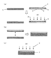
- FIG. 1 is a process chart showing a first embodiment of a manufacturing process of an optical member using the ultraviolet curable adhesive composition of the present invention.
- This method is a method of obtaining an optical member by bonding the liquid crystal display unit 1 and the transparent substrate 2.
- the liquid crystal display unit 1 refers to one in which a liquid crystal material is sealed between a pair of substrates on which electrodes are formed, and in which a polarizing plate, a drive circuit, a signal input cable, and a backlight unit are provided.
- the transparent substrate 2 is a transparent substrate such as a glass plate, a polymethyl methacrylate (PMMA) plate, a polycarbonate (PC) plate, and an alicyclic polyolefin polymer (COP) plate.
- PMMA polymethyl methacrylate
- PC polycarbonate
- COP alicyclic polyolefin polymer
- the transparent substrate 2 one having a black frame-shaped light shielding portion 4 on the surface of the transparent substrate can be suitably used, and the light shielding portion 4 is formed by sticking of a tape, coating of paint, printing or the like.
- the present invention can be applied to those not having the light shielding portion 4, in the following description of the first to third embodiments, the case where the light shielding portion 4 is provided will be described as a specific example. In the case where the light shielding portion 4 is not provided, if “a transparent substrate having a light shielding portion” is read as a “transparent substrate”, it can be considered as an example where the light shielding portion is not provided.
- a UV curable adhesive composition is applied to the surface of the liquid crystal display unit 1 and the surface of the transparent substrate 2 having the light shielding portion on which the light shielding portion is formed.
- the coating method may, for example, be a slit coater, a roll coater, a spin coater, or a screen printing method.
- the UV curable adhesive composition applied to the surface of the liquid crystal display unit 1 and the transparent substrate 2 having the light shielding portion may be the same, or different UV curable adhesive compositions may be used. . It is usually preferred that both be the same UV curable adhesive composition.
- the film thickness of the cured product of each ultraviolet curable resin is adjusted so that the thickness of the cured resin layer 7 after bonding is 50 to 500 ⁇ m, preferably 50 to 350 ⁇ m, and more preferably 100 to 350 ⁇ m.
- the film thickness of the cured product layer of the UV curable resin present on the surface of the transparent substrate 2 having the light shielding part depends on the film thickness, the UV curing normally present on the surface of the liquid crystal display unit 1 It is preferable that the thickness be equal to or larger than the thickness of the cured product layer of the mold resin. This is to minimize the portion remaining uncured even after irradiation with ultraviolet light in step 3 described later, thereby eliminating the possibility of curing failure.
- the UV curable adhesive composition layer 5 after application is irradiated with UV light 8 to cure the lower portion of the coated layer (on the liquid crystal display unit side or the transparent substrate side as viewed from the UV curable adhesive composition) (
- the uncured part (not shown in the figure) present on the upper side of the coating layer (the side opposite to the liquid crystal display unit side or the side opposite to the transparent substrate side) (air side when performed in the atmosphere)
- a cured product layer 6 is obtained.
- the irradiation dose is preferably 5 to 2000 mJ / cm 2 , particularly preferably 10 to 1000 mJ / cm 2 . If the amount of irradiation is too small, the degree of curing of the resin of the finally bonded optical member may be insufficient.
- uncured refers to a fluidizable state at 25 ° C. environment. Moreover, when an adhesive composition layer is touched with a finger after ultraviolet irradiation and a liquid component adheres to a finger, it is judged that it has an unhardened part.
- any light source may be used as long as it is a lamp that emits ultraviolet to near-ultraviolet light.
- the wavelength of the ultraviolet light irradiated to the ultraviolet-curable adhesive composition is not particularly limited, but when the maximum illuminance in the range of 320 nm to 450 nm is 100, the maximum illuminance at 200 to 320 nm
- the ratio (illumination ratio) is preferably 30 or less, and particularly preferably 10 or less at 200 to 320 nm.
- the adhesive strength of the finally obtained optical member will be poor. This is because if the illuminance at a low wavelength is high, the curing of the ultraviolet curable adhesive composition proceeds excessively at the time of curing in Step 1, and the contribution to the adhesion at the time of curing in ultraviolet irradiation in Step 3 decreases. It is thought that it is because it does.
- a method of irradiating the ultraviolet ray so as to obtain the above illumination ratio for example, a method of applying a lamp satisfying the condition of the illumination ratio as a lamp for irradiating ultraviolet to near-ultraviolet light rays;
- a base material for example, a short wave ultraviolet cut filter, a glass plate, a film, etc.
- a base material for example, a short wave ultraviolet cut filter, a glass plate, a film, etc.
- step 1 irradiation with ultraviolet light is usually performed in the air at the upper surface on the coating side (the side opposite to the liquid crystal display unit side or the side opposite to the transparent substrate side from the ultraviolet curable adhesive composition) (normal air) It is preferable to irradiate from surface.
- UV rays may be irradiated in a vacuum environment or environment of a gas such as nitrogen that does not cause curing inhibition.
- a gas for example, nitrogen
- the state of the uncured portion and the film thickness of the uncured portion can be adjusted. That is, by blowing oxygen or ozone to the surface of the coating layer, oxygen inhibition of the curing of the ultraviolet curable adhesive composition occurs on the surface, so that the uncured portion of the surface is ensured, or uncured.
- the film thickness of the portion can be increased.
- Step 2 Next, as shown in FIG. 1B, the liquid crystal display unit 1 and the transparent substrate 2 having the light shielding portion are bonded to each other such that the uncured portions face each other. Bonding can be performed either in the air or in a vacuum. Here, in order to prevent the formation of air bubbles during bonding, bonding in vacuum is preferable. As described above, when a cured product of an ultraviolet curable resin having a cured portion and an uncured portion on each of the liquid crystal display unit and the transparent substrate is obtained and then bonded, improvement in adhesion can be expected. Bonding can be performed by pressing, pressing or the like.
- UV rays 8 are irradiated to the optical member obtained by bonding the transparent substrate 2 and the liquid crystal display unit 1 from the side of the transparent substrate 2 having the light shielding portion.
- the adhesive composition (coated layer) is cured.
- the dose of ultraviolet rays is preferably about 100 ⁇ 4000mJ / cm 2 in accumulated light quantity, particularly preferably 200 ⁇ 3000mJ / cm 2 approximately.
- any light source may be used as long as it is a lamp that irradiates ultraviolet to near-ultraviolet light.
- low-pressure, high-pressure or ultra-high pressure mercury lamps, metal halide lamps, (pulsed) xenon lamps, electrodeless lamps and the like can be mentioned.
- an optical member as shown in FIG. 8 can be obtained.
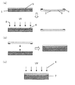
- the optical member of the present invention may be manufactured by the following modified second embodiment.
- the details of each step are the same as those in the first embodiment described above, and thus the description of the same parts will be omitted.
- Step 1 First, as shown in FIG. 2 (a), an ultraviolet-curable composition is applied to the surface of the transparent substrate 2 having the light-shielding portion on the surface on which the light-shielding portion 4 is formed.
- the adhesive composition layer 5) is irradiated with ultraviolet light 8, and the cured portion present on the lower side of the coating layer (the transparent substrate side as viewed from the ultraviolet curable adhesive composition) and the upper side of the coating layer (transparent substrate side) And a cured product layer 6 having an uncured portion present on the opposite side of
- the wavelength of the ultraviolet light irradiated to the ultraviolet curable adhesive composition is not particularly limited, but when the maximum illuminance in the range of 320 nm to 450 nm is 100, the ratio of the maximum illuminance at 200 to 320 nm is 30 or less
- the illuminance at 200 to 320 nm is preferably 10 or less. Assuming that the maximum illuminance in the range of 320 nm to
- Step 2 Next, as shown in FIG. 2 (b), the transparent substrate 2 having the liquid crystal display unit 1 and the light shielding portion in such a manner that the uncured portion of the obtained cured product layer 6 and the display surface of the liquid crystal display unit 1 Paste together. Bonding can be performed either in the air or in a vacuum.
- Step 3 Next, as shown in FIG. 2 (c), ultraviolet rays 8 are irradiated to the optical member obtained by bonding the transparent substrate 2 and the liquid crystal display unit 1 from the side of the transparent substrate 2 having the light shielding portion.
- the cured product layer 6 having the uncured portion of the adhesive composition is cured.
- FIG. 3 is a process chart showing a third embodiment of a method for producing an optical member using the ultraviolet-curable adhesive composition of the present invention.
- the details of each step are the same as those in the first embodiment described above, and thus the description of the same parts will be omitted.
- the same members as those in the first embodiment described above are designated by the same reference numerals in the drawings, and the description thereof will not be repeated here.
- Step 1 First, as shown in FIG. 3A, the ultraviolet curable composition was applied to the surface of the liquid crystal display unit 1. Thereafter, the ultraviolet curable adhesive composition layer 5 is irradiated with the ultraviolet light 8 so that the lower side 8 of the coating layer 8 the cured portion present on the transparent substrate side as viewed from the ultraviolet curable adhesive composition, and the upper portion of the coating layer A cured product layer 6 having uncured portions present on the side (opposite to the transparent substrate side) is obtained.
- the wavelength of the ultraviolet light irradiated to the ultraviolet curable adhesive composition is not particularly limited, but when the maximum illuminance in the range of 320 nm to 450 nm is 100, the maximum illuminance at 200 to 320 nm is preferably 30 or less Particularly preferably, the illuminance at 200 to 320 nm is 10 or less. Assuming that the maximum illuminance in the range of 320 nm to 450 nm is 100, if the maximum illuminance at 200 to 320 nm is higher than 30, the adhesive strength of the finally obtained optical member is inferior.
- Step 2 Next, as shown in FIG. 3B, the liquid crystal display unit 1 is formed such that the surface on which the light shielding portion is formed on the transparent substrate 2 having the light shielding portion and the uncured portion of the obtained cured product layer 6 faces each other. And a transparent substrate 2 having a light shielding portion. Bonding can be performed either in the air or in a vacuum.
- Step 3 Next, as shown in FIG. 3C, ultraviolet rays 8 are irradiated to the optical member obtained by bonding the transparent substrate 2 and the liquid crystal display unit 1 from the side of the transparent substrate 2 having the light shielding portion, thereby achieving ultraviolet curing.
- the cured product layer 6 having the uncured portion of the adhesive composition is cured.
- each of the above-described embodiments describes some of the embodiments of the method for producing an optical member of the present invention as one specific optical substrate.
- a transparent substrate having a liquid crystal display unit and a light shielding portion is used.
- various members described later can be used as an optical substrate in place of the liquid crystal display unit, and various members described later can be used as an optical substrate also for the transparent substrate. be able to.
- optical substrates such as liquid crystal display units and transparent substrates, other optical substrate layers (for example, a cured product layer of an ultraviolet curable adhesive composition) are further bonded to these various members.
- a laminated film or other optical substrate layer may be used.
- the coating method of the ultraviolet curable adhesive composition, the film thickness of the resin cured product, the irradiation amount and the light source at the time of ultraviolet irradiation described in the section of the first embodiment, and the ultraviolet curable resin layer surface The method of adjusting the film thickness of the uncured portion by blowing oxygen or nitrogen or ozone is not limited to the above embodiment, but can be applied to any manufacturing method included in the present invention.
- At least one optical substrate having a light shielding portion is selected from the group consisting of a transparent glass substrate having a light shielding portion, a transparent resin substrate having a light shielding portion, and a glass substrate on which a light shielding portion and a transparent electrode are formed.
- One optical substrate is a protective substrate having a light shielding portion, and another optical substrate bonded thereto is a touch panel or a display unit having a touch panel, and at least two optical substrates are bonded
- the ultraviolet curable adhesive composition as described above is applied to the surface provided with the light shielding portion of the protective substrate having the light shielding portion, or to one or both surfaces of the touch surface of the touch panel. Is preferably applied.
- One optical substrate is an optical substrate having a light shielding portion, another optical substrate to be bonded thereto is a display unit, and an optical member to which at least two optical substrates are bonded is
- the aspect which is a display body unit which has an optical base material which has a light-shielding part.
- the above-mentioned UV-curable adhesive is applied to the optical substrate having the light shielding portion on the side provided with the light shielding portion, the display surface of the display unit, or both of them. It is preferred to apply the agent composition.
- the optical member is It can be used in the method of manufacturing.
- the cure shrinkage of the cured product of the ultraviolet-curable adhesive composition of the present invention is preferably 4.0% or less, and particularly preferably 3.0% or less.
- the transmittance of the cured product of the ultraviolet curable adhesive composition of the present invention at 400 nm to 800 nm is preferably 90% or more.
- the transmittance at 400 to 450 nm is 90% or more, since the visibility can be further improved when the transmittance at 400 to 450 nm of the cured product is high.
- the UV curable adhesive composition of the present invention is for producing an optical member by laminating a plurality of optical substrates according to the above (Step 1) to (Step 2), and if necessary, (Step 3).
- an optical base material used in the manufacturing method of the optical member of this invention a transparent plate, a sheet
- optical substrate means both an optical substrate having no light shielding portion on the surface and an optical substrate having a light shielding portion on the surface.
- at least one of a plurality of optical substrates used is an optical substrate having a light shielding portion.
- the optical substrate having a light shielding portion for example, a protective plate for a display screen having a light shielding portion or a touch panel provided with a protective substrate having a light shielding portion can be mentioned.
- the optical substrate having the light shielding portion is a protective plate for a display screen having the light shielding portion
- the light shielding portion has a light shielding portion. It is the surface on the side where the part is provided.
- the protective substrate having the light shielding portion has the surface having the light shielding portion bonded to the touch surface of the touch panel.
- the surface on the side where the light shielding portion of the optical base material having the light shielding portion is provided means the substrate surface of the touch panel opposite to the touch surface of the touch panel.
- the position of the light shielding portion in the optical substrate having the light shielding portion is not particularly limited.
- a band-shaped light shielding portion having a width of about 0.05 to 20 mm, preferably about 0.05 to 10 mm, and more preferably about 0.1 to 6 mm is formed at the periphery of the optical substrate. Cases may be mentioned.
- the light shielding portion on the optical substrate can be formed by sticking of a tape, coating of a paint, printing, or the like.
- the optical substrate used in the present invention is a sheet or transparent plate obtained by laminating a plurality of films or sheets such as polarizing plates, a sheet or transparent plate not laminated, and a transparent plate made of inorganic glass Plates (inorganic glass plates and their processed products such as lenses, prisms, ITO glass) and the like can be used.
- a transparent plate or sheet is a sheet or transparent plate obtained by laminating a plurality of films or sheets such as polarizing plates, a sheet or transparent plate not laminated, and a transparent plate made of inorganic glass Plates (inorganic glass plates and their processed products such as lenses, prisms, ITO glass) and the like can be used.
- the optical base material used in the present invention is a laminate comprising a plurality of functional plates or sheets such as a touch panel (touch panel input sensor) or a display unit described below in addition to the above-mentioned polarizing plate etc. Also referred to as "body”.
- a sheet which can be used as an optical base material used for the present invention an icon sheet, a makeup sheet, and a protection sheet are mentioned.
- a board (transparent board) which can be used for the manufacturing method of the optical member of the present invention a decorative board and a guard board are mentioned.
- materials of these sheets or plates those listed as materials of the transparent plate can be applied. Examples of the material of the touch panel surface that can be used as an optical substrate used in the present invention include glass, PET, PC, PMMA, a composite of PC and PMMA, COC, and COP.
- the thickness of the plate-like or sheet-like optical substrate such as a transparent plate or sheet is not particularly limited, and usually about 5 ⁇ m to about 5 cm, preferably about 10 ⁇ m to about 10 mm, more preferably about 50 ⁇ m to about 3 mm It is a thickness.
- a display unit with an optical functional material is used by using a display unit such as a liquid crystal display as one of the optical substrates and using an optical functional material as another optical substrate.
- a display panel As said display unit, display apparatuses, such as LCD which stuck the polarizing plate to glass, EL display, EL illumination, electronic paper, and a plasma display, are mentioned, for example.
- transparent plastic boards such as an acrylic board, PC board, PET board, PEN board, tempered glass, a touch panel input sensor are mentioned.
- the optical substrate When the optical substrate is used as an adhesive to bond, when the refractive index of the cured product is 1.45 to 1.55 to improve visibility, the visibility of the displayed image is further improved. . If it is in the range of the said refractive index, the difference of the refractive index with the base material used as an optical base material can be reduced, and it becomes possible to suppress irregular reflection of light and to reduce an optical loss.
- optical member in which an optical substrate having a light shielding portion and the functional laminate are bonded together using a cured product of the ultraviolet curable adhesive composition of the present invention.
- An optical base selected from the group consisting of a transparent glass substrate having a light shielding part, a transparent resin substrate having a light shielding part, and a glass substrate on which a light shielding material and a transparent electrode are formed.
- the display unit is any of a liquid crystal display unit, a plasma display unit and an organic EL display unit.
- a touch panel or touch panel input in which a plate-like or sheet-like optical substrate having a light shielding portion is bonded to the surface on the touch surface side of the touch panel using the cured product of the ultraviolet curable adhesive composition of the present invention sensor).
- V A display panel in which a plate-like or sheet-like optical substrate having a light shielding portion is pasted on a display screen of a display unit using a cured product of the ultraviolet curable adhesive composition of the present invention.
- the UV curable adhesive composition may be applied to only one of the surfaces facing each other through the cured material layer in the two optical substrates to be bonded, or may be applied to both surfaces. Also good.
- any one surface of the protective substrate having a light shielding portion, preferably the light shielding portion in Step 1
- the adhesive composition may be applied to only one of the provided surface and the touch surface of the touch panel or the display surface of the display unit, or may be applied to both of them.
- the optical member of said (vi) which bonded the display base unit to the protection base material or touch panel for protecting the display screen of a display body unit the light-shielding part of the protection base material was provided in process 1.
- the adhesive composition may be applied to only one of the substrate surface opposite to the surface or the touch surface of the touch panel and the display surface of the display unit, or may be applied to both of them.
- the optical member including the display body knit obtained by the manufacturing method of the present invention and the optical base having the light shielding portion can be incorporated into an electronic device such as a television, a small game machine, a mobile phone, a personal computer and the like.
- B1 Urethane acrylate (polypropylene glycol (molecular weight: 3000), isophorone diisocyanate, and a reactant of three components of 2-hydroxyethyl acrylate in a molar ratio of 1: 1.3: 2)
- B2 Urethane acrylate (hydrogenated polybutadiene diol (molecular weight 2000), isophorone diisocyanate, and a reactant of three components of 2-hydroxyethyl acrylate in a molar ratio of 1: 1.2: 2)
- C2 S-1800A (isostearyl acrylate, manufactured by Shin-Nakamura Chemical Co., Ltd.)
- compositions 1 to 20 were obtained using the obtained compositions a to d, the mixture was heated and mixed at the compounding ratio shown in Table 3 to prepare compositions 1 to 20.
- the composition described in Table 3 was blended, and after blending, it was stored for one week in a 25 ° C. environment. After storage, the resin composition is taken out of the storage area, stirred at 200 rpm for 30 minutes with a disper (stirrer: Three-One Motor BL300 manufactured by Shinto Kagaku Co., Ltd., stirring blade: width x width x 1 cm x 10 cm x 10 cm) and stirred for 30 minutes. A lot of air bubbles were mixed in.
- the composition was applied to a 10 cm ⁇ 10 cm size glass substrate to have a film thickness of 200 ⁇ m and an area of 8 cm ⁇ 8 cm. After application, it was allowed to stand at a flat place for 10 minutes, and the state of the applied composition was visually confirmed. The results are shown in Table 4. :: less than 8.4 cm on each of four sides of the surface on which the composition is applied. Fair: Any one or more sides of the surface on which the composition is applied is 8.4 cm or more. X: Any one or more sides of the surface to which the composition is applied is 8.4 cm or more, and the application surface is roughened in a rough shape.
- compositions 1 to 20 were stirred with a disper at 200 rpm for 30 minutes to mix a large amount of air bubbles into the composition. Thereafter, 100 g of the composition obtained above is placed in a 300 mL beaker with an inner diameter of 78 mm, the beaker is placed in a bell-type vacuum degassing vessel, the internal pressure is allowed to stand for 10 minutes under a reduced pressure environment of 500 Pa, and the composition after reduced pressure processing I got a thing.
- a slide glass of 0.8 mm in thickness and an acrylic plate of 0.8 mm in thickness were prepared, and the composition obtained on one side was coated to a film thickness of 200 ⁇ m, and then the other was attached to the coated surface. .
- the resin composition was irradiated with ultraviolet light of an integrated light quantity of 2000 mJ / cm 2 with a high pressure mercury lamp (80 W / cm, ozone-free) through a glass to cure the resin composition, and a sample for evaluating adhesion was prepared. This was left for 250 hours in an 85 ° C., 85% RH environment. In the evaluation sample, peeling of the slide glass or the acrylic plate from the cured resin was confirmed visually, but no peeling was observed.
- the transmittance in the wavelength region of 400 to 800 nm and 400 to 450 nm was measured using a spectrophotometer (U-3310, Hitachi High-Technologies Corporation). As a result, the transmittance of 400 to 800 nm was 90% or more, and the transmittance of 400 to 450 nm was 90% or more.
- the composition is applied to a thickness of 125 ⁇ m on the surface of a transparent substrate having a light shielding portion (width 5 mm) on the display surface and outer peripheral portion of a liquid crystal display unit having an area of 3.5 inches It applied so that it might become. Then, using an electrodeless ultraviolet lamp (D bulb, manufactured by Heraeus Noble Light Fusion U.V.) in the coated layer obtained, the integrated light quantity 100 mJ / from the air side through an ultraviolet cut filter that blocks a wavelength of 320 nm or less. Ultraviolet irradiation of cm 2 was performed to form a cured product layer having a cured portion and an uncured portion present on the air side.
- D bulb manufactured by Heraeus Noble Light Fusion U.V.
- the ratio of the maximum illuminance in the range of 200 to 320 nm was 3 when the maximum illuminance in the range of 320 nm to 450 nm was 100, and the ultraviolet light irradiated to the composition at this time was 100.
- the transparent substrate which has a liquid crystal display unit and a light-shielding part in the form which an unhardened part opposes was bonded.
- the resin cured product layer is cured by irradiating ultraviolet rays with an integrated light quantity of 2000 mJ / cm 2 from the glass substrate side having the light shielding part with an ultra-high pressure mercury lamp (TOSCURE 752, manufactured by Harrison Toshiba Lighting Co., Ltd.), Made.
- the transparent substrate was removed from the obtained optical member, and the cured resin layer in the light shielding portion was washed away with heptane, and then the cured state was confirmed. There was no evidence that the uncured resin composition had been removed, and the resin of the light shielding portion was sufficiently cured.
Landscapes
- Physics & Mathematics (AREA)
- Chemical & Material Sciences (AREA)
- Organic Chemistry (AREA)
- Nonlinear Science (AREA)
- General Physics & Mathematics (AREA)
- Mathematical Physics (AREA)
- Crystallography & Structural Chemistry (AREA)
- Optics & Photonics (AREA)
- Engineering & Computer Science (AREA)
- Theoretical Computer Science (AREA)
- Adhesives Or Adhesive Processes (AREA)
Abstract
本発明は、塗布性、硬化性が良く、さらに貼り合わせ時の光学部材と樹脂組成物界面の気泡だけではなく、樹脂組成物内部に発生する気泡を抑制し、高い視認性を得ることができる紫外線硬化型樹脂組成物及びそれを用いた製造方法を提供することを目的とする。 (1)タッチパネル用樹脂組成物であって、25℃の環境下で樹脂組成物を容器に入れ、ディスパーで200rpm、30分間撹拌させて気泡を混入させた後、容器を釣鐘式減圧脱泡器に入れて内圧を500Paの減圧環境下で100μm以上の気泡が消失するまでの時間が30分以下であることを特徴とするタッチパネル用紫外線硬化型接着剤組成物。
Description
本発明は、少なくとも2つの光学基材を貼り合わせるための紫外線硬化型接着剤組成物と、それを用いた光学部材を製造する方法に関する。
近年、液晶ディスプレイ、プラズマディスプレイ、有機ELディスプレイ等の表示装置の表示画面にタッチパネルを貼り合わせ、画面入力を可能とした表示装置が広く利用されている。このタッチパネルは、透明電極が形成されたガラス板又は樹脂製フィルムが僅かな隙間を空けて向き合って貼り合されており、必要に応じて、そのタッチ面の上に、ガラス又は樹脂製の透明保護板を貼り合せた構造を有している。
タッチパネルにおける透明電極が形成されたガラス板又はフィルムと、ガラス又は樹脂製の透明保護板との貼り合せ、又はタッチパネルと表示体ユニットの貼り合わせには、両面粘着シートを用いる技術がある。しかし、両面粘着シートを用いると気泡が入りやすいという問題があった。両面粘着シートに代わる技術として、柔軟性のある紫外線硬化型接着剤組成物で貼り合せる技術が提案されている。
一方で、タッチパネルと表示体ユニットを紫外線硬化型接着剤で貼り合わせる際、貼り合わせ面内に気泡が入り込み視認性が低下してしまうという問題あった。気泡が入り込む位置は大きく分けて2種類存在し、一つは貼り合わせ工程で貼り合わせ基材と樹脂組成物の界面に発生する気泡、もう一つは樹脂組成物内部に発生する気泡である。
紫外線硬化型樹脂組成物を使用して光学基材を貼り合わせて光学部材を製造する方法として、特許文献1では、押圧手段を基板上で移動させて濡れ広げる方法により、貼り合わせ時に気泡の混入を防止する技術が開示されている。また、特許文献2では真空中で基材を貼り合わせることにより、光学部材内部への気泡混入を防止する技術が開示されている。しかしながら、特許文献1および特許文献2では樹脂組成物内部に存在する気泡については全く考慮されておらず、当該問題の解決手段としては不十分であった。すなわち、従来の技術で貼り合わせ基材と樹脂組成物の界面に発生する気泡は防ぐことができたとしても、紫外線硬化型樹脂組成物内部に発生する気泡に対しては有効な解決手段が提案されてこなかった。
本発明は、塗布性、硬化性が良く、さらに貼り合わせ時の光学部材と樹脂組成物界面の気泡だけではなく、樹脂組成物内部に発生する気泡を抑制し、高い視認性を得ることができる紫外線硬化型樹脂組成物及びそれを用いた製造方法を提供することを目的とする。
本発明者らは前記課題を解決するため鋭意研究の結果、本発明を完成した。即ち、本発明は、下記(1)~(12)に関する。
(1)タッチパネル用樹脂組成物であって、25℃の環境下で樹脂組成物を容器に入れ、ディスパーで200rpm、30分間撹拌させて気泡を混入させた後、容器を減圧脱泡器に入れて内圧を500Paの、減圧環境下で100μm以上の気泡が消失するまでの時間が30分以下であることを特徴とするタッチパネル用紫外線硬化型接着剤組成物
(2)少なくとも2つの光学基材を貼り合わせるために用いる樹脂組成物であって、消泡剤(A)、光重合性オリゴマー(B)、光重合性モノマー(C)、光重合開始剤(D)を含むことを特徴とする(1)に記載のタッチパネル用紫外線硬化型接着剤組成物。
(3)光重合性オリゴマー(B)が、ウレタン(メタ)アクリレート、ポリプロピレン、ポリブタジエン、水添ポリブタジエン、ポリイソプレン及び水添ポリイソプレンからなる群から選ばれる少なくとも1種の骨格をもつ(メタ)アクリレートであることを特徴とする(1)又は(2)に記載のタッチパネル用紫外線硬化型接着剤組成物。
(4)光重合性オリゴマー(B)が、ポリプロピレン、ポリブタジエン、水添ポリブタジエン、ポリイソプレン及び水添ポリイソプレンからなる群から選ばれる少なくとも1種の骨格をもつウレタン(メタ)アクリレートであることを特徴とする(1)~(3)のいずれか一項に記載のタッチパネル用紫外線硬化型接着剤組成物。
(5)消泡剤(A)の含有量が0.001~5重量%の範囲であることを特徴とする(1)~(4)のいずれか一項に記載のタッチパネル用紫外線硬化型接着剤組成物。
(6)さらに、柔軟化成分(E)を含むことを特徴とする(1)~(5)のいずれか一項に記載のタッチパネル用紫外線硬化型接着剤組成物。
(7)柔軟化成分(E)として、ヒドロキシル基含有ポリマー、テルペン系樹脂、水添テルペン系樹脂、ロジン系樹脂及び水添ロジン系樹脂からなる群から選ばれる少なくとも1種を含有することを特徴とする(6)に記載のタッチパネル用紫外線硬化型接着剤組成物。
(8)樹脂組成物の表面張力が20mN/m以上であることを特徴とする(1)~(7)のいずれか一項に記載のタッチパネル用紫外線硬化型接着剤組成物。
(9)消泡剤(A)が非シリコン系ポリマーを含有することを特徴とする(1)~(8)のいずれか一項に記載のタッチパネル用紫外線硬化型接着剤組成物。
(10)下記工程1~2を有する少なくとも2つの光学基材が貼りあわされた光学部材の製造方法。
(工程1)少なくとも一つの光学基材に対して、(1)~(9)のいずれか一項に記載のタッチパネル用紫外線硬化型接着剤組成物を塗布して、塗布層を形成し、該塗布層に紫外線を照射することにより硬化物層を有する光学基材を得る工程
(工程2)工程1で得られた光学基材の硬化物層に対して、他の光学基材を貼り合わせるか、又は、工程1により得られた他の光学基材の硬化物層を貼り合わせる工程
(11)(1)~(9)のいずれか一項に記載の紫外線硬化型接着剤組成物に活性エネルギー線を照射して得られる硬化物。
(12)(1)~(9)のいずれか一項に記載の紫外線硬化型接着剤組成物を用いてなることを特徴とするタッチパネル。
(1)タッチパネル用樹脂組成物であって、25℃の環境下で樹脂組成物を容器に入れ、ディスパーで200rpm、30分間撹拌させて気泡を混入させた後、容器を減圧脱泡器に入れて内圧を500Paの、減圧環境下で100μm以上の気泡が消失するまでの時間が30分以下であることを特徴とするタッチパネル用紫外線硬化型接着剤組成物
(2)少なくとも2つの光学基材を貼り合わせるために用いる樹脂組成物であって、消泡剤(A)、光重合性オリゴマー(B)、光重合性モノマー(C)、光重合開始剤(D)を含むことを特徴とする(1)に記載のタッチパネル用紫外線硬化型接着剤組成物。
(3)光重合性オリゴマー(B)が、ウレタン(メタ)アクリレート、ポリプロピレン、ポリブタジエン、水添ポリブタジエン、ポリイソプレン及び水添ポリイソプレンからなる群から選ばれる少なくとも1種の骨格をもつ(メタ)アクリレートであることを特徴とする(1)又は(2)に記載のタッチパネル用紫外線硬化型接着剤組成物。
(4)光重合性オリゴマー(B)が、ポリプロピレン、ポリブタジエン、水添ポリブタジエン、ポリイソプレン及び水添ポリイソプレンからなる群から選ばれる少なくとも1種の骨格をもつウレタン(メタ)アクリレートであることを特徴とする(1)~(3)のいずれか一項に記載のタッチパネル用紫外線硬化型接着剤組成物。
(5)消泡剤(A)の含有量が0.001~5重量%の範囲であることを特徴とする(1)~(4)のいずれか一項に記載のタッチパネル用紫外線硬化型接着剤組成物。
(6)さらに、柔軟化成分(E)を含むことを特徴とする(1)~(5)のいずれか一項に記載のタッチパネル用紫外線硬化型接着剤組成物。
(7)柔軟化成分(E)として、ヒドロキシル基含有ポリマー、テルペン系樹脂、水添テルペン系樹脂、ロジン系樹脂及び水添ロジン系樹脂からなる群から選ばれる少なくとも1種を含有することを特徴とする(6)に記載のタッチパネル用紫外線硬化型接着剤組成物。
(8)樹脂組成物の表面張力が20mN/m以上であることを特徴とする(1)~(7)のいずれか一項に記載のタッチパネル用紫外線硬化型接着剤組成物。
(9)消泡剤(A)が非シリコン系ポリマーを含有することを特徴とする(1)~(8)のいずれか一項に記載のタッチパネル用紫外線硬化型接着剤組成物。
(10)下記工程1~2を有する少なくとも2つの光学基材が貼りあわされた光学部材の製造方法。
(工程1)少なくとも一つの光学基材に対して、(1)~(9)のいずれか一項に記載のタッチパネル用紫外線硬化型接着剤組成物を塗布して、塗布層を形成し、該塗布層に紫外線を照射することにより硬化物層を有する光学基材を得る工程
(工程2)工程1で得られた光学基材の硬化物層に対して、他の光学基材を貼り合わせるか、又は、工程1により得られた他の光学基材の硬化物層を貼り合わせる工程
(11)(1)~(9)のいずれか一項に記載の紫外線硬化型接着剤組成物に活性エネルギー線を照射して得られる硬化物。
(12)(1)~(9)のいずれか一項に記載の紫外線硬化型接着剤組成物を用いてなることを特徴とするタッチパネル。
まず、本発明の紫外線硬化型接着剤組成物について説明する。
本発明のタッチパネル用紫外線硬化型接着剤組成物は、少なくとも2つの光学基材を貼り合わせるために用いる樹脂組成物であって、光重合性オリゴマー(B)、光重合性モノマー(C)、光重合開始剤(D)を含有する。また、任意成分として、光学用に使用する紫外線硬化型接着剤組成物に添加可能なその他の成分を含有することができる。また、本発明は、25℃の環境下で樹脂組成物を容器に入れ、ディスパーで200rpm、30分間撹拌させて気泡を混入させた後、容器を釣鐘式減圧脱泡器に入れて内圧を500Paの減圧環境下で100μm以上の気泡が消失するまでの時間が30分以下であることを特徴とするタッチパネル用樹脂組成物である。
なお、「光学用に使用する紫外線硬化型樹脂組成物に添加可能」とは、硬化物の透明性を、光学用に使用出来ない程度に低下させる添加物が含まれないことを意味する。
本発明に使用する紫外線硬化型樹脂組成物で、硬化後の厚さが200μmとなる硬化物のシートを作製したとき、該シートの、400~800nmの波長の光での好ましい平均透過率は、少なくとも90%である。 該紫外線硬化型樹脂組成物の組成割合としては、好適には消泡剤(A)が0.001~10重量%、光重合性オリゴマー(B)が5~90重量%、光重合性モノマー(C)が5~90重量%、光重合開始剤(D)が0.1~5重量%、その他の成分が残部である。
本発明の紫外線硬化型樹脂組成物において、光重合開始剤(D)としては、通常使用されている光重合開始剤は何れも使用出来る。
本発明のタッチパネル用紫外線硬化型接着剤組成物は、少なくとも2つの光学基材を貼り合わせるために用いる樹脂組成物であって、光重合性オリゴマー(B)、光重合性モノマー(C)、光重合開始剤(D)を含有する。また、任意成分として、光学用に使用する紫外線硬化型接着剤組成物に添加可能なその他の成分を含有することができる。また、本発明は、25℃の環境下で樹脂組成物を容器に入れ、ディスパーで200rpm、30分間撹拌させて気泡を混入させた後、容器を釣鐘式減圧脱泡器に入れて内圧を500Paの減圧環境下で100μm以上の気泡が消失するまでの時間が30分以下であることを特徴とするタッチパネル用樹脂組成物である。
なお、「光学用に使用する紫外線硬化型樹脂組成物に添加可能」とは、硬化物の透明性を、光学用に使用出来ない程度に低下させる添加物が含まれないことを意味する。
本発明に使用する紫外線硬化型樹脂組成物で、硬化後の厚さが200μmとなる硬化物のシートを作製したとき、該シートの、400~800nmの波長の光での好ましい平均透過率は、少なくとも90%である。 該紫外線硬化型樹脂組成物の組成割合としては、好適には消泡剤(A)が0.001~10重量%、光重合性オリゴマー(B)が5~90重量%、光重合性モノマー(C)が5~90重量%、光重合開始剤(D)が0.1~5重量%、その他の成分が残部である。
本発明の紫外線硬化型樹脂組成物において、光重合開始剤(D)としては、通常使用されている光重合開始剤は何れも使用出来る。
本発明においては、泡切れの良い樹脂組成物を用いる。泡切れ時間は以下のように測定することができる。
樹脂組成物の(A)~(D)成分を配合する。そして、配合後1週間以上樹脂組成物を保管する。保管後、樹脂組成物を保管場所から取り出し、室温(25℃)で放置後、ディスパーで200rpm、30分間撹拌させて組成物中に多量の気泡を混入させる。その後、内径78mmの300mLビーカーに組成物を100g入れ、ビーカーを減圧脱泡器(例えば、釣鐘式減圧脱泡器)に入れ、内圧を500Pa減圧環境下で液内、液面の目視できるすべての気泡(100μm以上の気泡)が消失するまでの時間を測定する。
そして、本発明においては、当該手法によってすべての気泡が消失するまでに要した時間が30分以下であることにより、硬化物内部における気泡の混入を防ぐことができ、優れた視認性を奏することができる。さらに、上記の優れた泡切れを有するものを使用して画像表示装置を作製することで、歩留りを顕著に向上することができる。
ここで、前記手法によってすべての気泡が消失するまでに要した時間が20分以下であることが好ましく、15分以下であることがより好ましく、10分以下であることが特に好ましく、5分以下であることが極めて好ましい。このような範囲にあることで、歩留りへの影響を顕著に向上させる作用が大きく高まるためである。
樹脂組成物の(A)~(D)成分を配合する。そして、配合後1週間以上樹脂組成物を保管する。保管後、樹脂組成物を保管場所から取り出し、室温(25℃)で放置後、ディスパーで200rpm、30分間撹拌させて組成物中に多量の気泡を混入させる。その後、内径78mmの300mLビーカーに組成物を100g入れ、ビーカーを減圧脱泡器(例えば、釣鐘式減圧脱泡器)に入れ、内圧を500Pa減圧環境下で液内、液面の目視できるすべての気泡(100μm以上の気泡)が消失するまでの時間を測定する。
そして、本発明においては、当該手法によってすべての気泡が消失するまでに要した時間が30分以下であることにより、硬化物内部における気泡の混入を防ぐことができ、優れた視認性を奏することができる。さらに、上記の優れた泡切れを有するものを使用して画像表示装置を作製することで、歩留りを顕著に向上することができる。
ここで、前記手法によってすべての気泡が消失するまでに要した時間が20分以下であることが好ましく、15分以下であることがより好ましく、10分以下であることが特に好ましく、5分以下であることが極めて好ましい。このような範囲にあることで、歩留りへの影響を顕著に向上させる作用が大きく高まるためである。
樹脂組成物の粘度が低い方が泡切れをよくする観点から好ましい。具体的には、室温(25℃)で300~50000mPa・sであることが好ましく、1500~10000mPa・sであることがより好ましく3000~5000mPa・sであることが特に好ましい。当該範囲に粘度を調整することで、気泡の消失速度を向上することができる。樹脂組成物内部に存在する気泡の有無の確認方法としては、組成物を透明の容器に移し、減圧環境下に置くことで確認することができる。
得られた樹脂組成物の表面張力が一定の範囲内にあることが、塗布性の観点から好ましい。本発明においては、樹脂組成物の表面張力が20~40mN/mであることが好ましく、22~32mN/mであることが特に好ましい。
本発明の紫外線硬化型接着剤組成物として、上記の泡切れを実現するために、消泡剤(A)を使用することが好ましい。消泡剤(A)としては、特には限定されず、一般的に工業用消泡剤/脱泡剤/破泡剤として販売されているものであれば任意で使用可能である。
消泡剤(A)として例えば、ビックケミー社製BYKシリーズ(BYK-051/052/054/055/057/063/065/066N/067A/077/081/088/088A/141/354/392/1752/1790/1791/1794/011/012/014/015/017/018/019/021/022/023/024/025/028/038/044/093/094/1610/1615/1650/1710/1711/1730/1740/1770/1780/1785/1798/A530/A555)、共栄社化学株式会社製フローレンシリーズ(AC-202/220F/247/253/265/300/300HF/300VF/303/303HF/324/326F/901/901HF/902/903/903HF/950/970MS/1160/1160HF/1170/1170HF/1190/1190HF/2000/2000HF/2200HF/2230EF/2300C、AO-5/82/98/106/108/108EF)、信越シリコーン社製KF-96、FA-630、X-50-1039A、KS-7708、KS-66、KSP-69、X-50-1105G、KS-602A、KSP-600、KS-508/530/531/537/538/540、東レ・ダウコーニング社製FSアンチフォームシリーズ(DB-110N/EPL/025/92/93/1224/1233/1277/013A)、SH5507、DK Q1-1247、AFE-1530、SM5572F、SM5571、旭化成ワッカーシリコーン社製AKシリーズ(AK-350/12500/60000)、AF98/1000、モメンティブ・パフォーマンス・マテリアルズ社製TSAシリーズ(TSA750/720/750S)等が挙げられる。
消泡性、および接着剤組成物の塗布性の観点から、無溶剤系、又は非水系溶剤が含有されているものが好ましく、非シリコーン系ポリマー消泡剤を含有することが特に好ましい。さらに非シリコーン系ポリマーのSP(溶解度パラメーター)値が8.0~9.5の範囲であることが好ましく、8.2~8.8の範囲であることが特に好ましい。必要に応じて二種以上を併用しても良く、非シリコーン系ポリマー消泡剤とシリコーン系消泡剤を併用しても良い。
消泡性、および接着剤組成物の塗布性の観点から、無溶剤系、又は非水系溶剤が含有されているものが好ましく、非シリコーン系ポリマー消泡剤を含有することが特に好ましい。さらに非シリコーン系ポリマーのSP(溶解度パラメーター)値が8.0~9.5の範囲であることが好ましく、8.2~8.8の範囲であることが特に好ましい。必要に応じて二種以上を併用しても良く、非シリコーン系ポリマー消泡剤とシリコーン系消泡剤を併用しても良い。
ここで、消泡性を向上させるためには、樹脂成分との相溶性が悪い消泡性と樹脂成分との組み合わせとすることが好適である。相溶性の基準として、溶解度パラメーターを用いることができる。そして、樹脂組成物の溶解度パラメーターで影響が大きい要因は、樹脂組成物中の最大含有量を占めている成分(以下、最大含有量成分)であることから、該最大含有量成分のSP値との差によって、好適な消泡剤と樹脂組成物の組み合わせを得ることが可能となる。具体的には、(非シリコーン系ポリマー消泡剤のSP値)-(最大含有量成分のSP値)が-0.1~0.6であることが好ましく、-0.05~0.3であることが特に好ましい。
(A)成分の含有量は、0.001~10重量%が好ましく、0.01~5重量%がより好ましく、さらに0.02~2重量%が特に好ましい。(A)成分の含有量が0.001%未満であると、消泡性が低下する。一方、10重量%以上であると、塗布性の低下やその他の成分と相溶性が悪くなり液の白濁を招く恐れがある。
本発明の紫外線硬化型接着剤組成物における光重合性オリゴマー(B)としては、特に限定されないが、ウレタン(メタ)アクリレート、ポリイソプレン又は水添ポリイソプレン骨格を有する(メタ)アクリレート、ポリブタジエン又は水添ポリブタジエン骨格を有する(メタ)アクリレートからなる群から選択されるいずれかを使用することが好ましい。中でも、接着強度の観点からウレタン(メタ)アクリレートが好ましく、さらに、耐湿性の観点から、ポリブタジエン/水添ポリブタジエン/ポリイソプレン/水添ポリイソプレンからなる群から選ばれる少なくとも1種以上の骨格をもつウレタン(メタ)アクリレートがより好ましい。
上記ウレタン(メタ)アクリレートは、例えば、多価アルコール、ポリイソシアネート及びヒドロキシル基含有(メタ)アクリレートを反応させることによって得られる。
多価アルコールとしては、例えば、ポリブタジエングリコール、水添ポリブタジエングリコール、ポリイソプレングリコール、水添ポリイソプレングリコール、ネオペンチルグリコール、3-メチル-1、5-ペンタンジオール、エチレングリコール、プロピレングリコール、1,4-ブタンジオール、1、6-ヘキサンジオール等の炭素数1~10のアルキレングリコール、トリメチロールプロパン、ペンタエリスリトール等のトリオール、トリシクロデカンジメチロール、ビス-〔ヒドロキシメチル〕-シクロヘキサン等の環状骨格を有するアルコール等;及びこれら多価アルコールと多塩基酸(例えば、コハク酸、フタル酸、ヘキサヒドロ無水フタル酸、テレフタル酸、アジピン酸、アゼライン酸、テトラヒドロ無水フタル酸等)との反応によって得られるポリエステルポリオール、多価アルコールとε-カプロラクトンとの反応によって得られるカプロラクトンアルコール、ポリカーボネートポリオール(例えば1,6-ヘキサンジオールとジフェニルカーボネートとの反応によって得られるポリカーボネートジオール等)又はポリエーテルポリオール(例えばポリエチレングリコール、ポリプロピレングリコール、ポリテトラメチレングリコール、エチレンオキサイド変性ビスフェノールA等)等が挙げられる。接着強度と耐湿性の観点から、上記多価アルコールとしては、プロピレングリコール、ポリブタジエングリコール、水添ポリブタジエングリコール、ポリイソプレングリコール、水添ポリイソプレングリコールが好ましく、透明性と柔軟性の観点から重量平均分子量が2000以上のプロピレングリコール、水添ポリブタジエングリコール、水添ポリイソプレングリコールが特に好ましい。耐熱着色性等の変色性、相溶性の観点から水添ポリブタジエングリコール、又はポリプロピレングリコールが好ましい。このときの重量平均分子量の上限は特に限定されないが、10000以下が好ましく、5000以下がより好ましい。また、必要に応じて二種以上の多価アルコールを併用してもよい。
有機ポリイソシアネートとしては、例えばイソホロンジイソシアネート、ヘキサメチレンジイソシアネート、トリレンジイソシアネート、キシレンジイソシアネート、ジフェニルメタン-4,4’-ジイソシアネート又はジシクロペンタニルイソシアネート等が挙げられる。中でも、強靭性の観点からイソホロンジイソシアネートが好ましい。
又、ヒドロキシル基含有(メタ)アクリレートとしては、例えばヒドロキシエチル(メタ)アクリレート、ヒドロキシプロピル(メタ)アクリレート、ヒドロキシブチル(メタ)アクリレート等のヒドロキシC2~C4アルキル(メタ)アクリレート、ジメチロールシクロヘキシルモノ(メタ)アクリレート、ヒドロキシカプロラクトン(メタ)アクリレート、ヒドロキシル基末端ポリアルキレングリコール(メタ)アクリレート等を使用することができる。
上記ウレタン(メタ)アクリレートを得るための反応は、例えば、以下のようにして行う。即ち、多価アルコールにその水酸基1当量あたり有機ポリイソシアネートをそのイソシアネート基が好ましくは1.1~2.0当量、さらに好ましくは1.1~1.5当量になるように混合し、反応温度を好ましくは70~90℃で反応させ、ウレタンオリゴマーを合成する。次いで、ウレタンオリゴマーのイソシアネート基1当量あたり、ヒドロキシ(メタ)アクリレート化合物をその水酸基が好ましくは1~1.5当量となるように混合し、70~90℃で反応させて目的とするウレタン(メタ)アクリレートを得ることができる。
上記ウレタン(メタ)アクリレートの重量平均分子量としては7000~100000程度が好ましく、10000~60000がより好ましい。重量平均分子量が7000より小さいと収縮が大きくなり、重量平均分子量が100000より大きいと硬化性が乏しくなる。また分子量分布(Mw/Mn)値が1.5以上であることが好ましい。
本発明の紫外線硬化型接着剤組成物においては、ウレタン(メタ)アクリレートは、1種または2種以上を任意の割合で混合して使用することができる。ウレタン(メタ)アクリレートの本発明の光硬化型透明接着剤組成物中における重量割合は通常5~90重量%、好ましくは10~50重量%である。
上記ポリイソプレン骨格を有する(メタ)アクリレートは、ポリイソプレン分子の末端又は側鎖に(メタ)アクリロイル基を有する。ポリイソプレン骨格を有する(メタ)アクリレートは「UC-203」(クラレ社製)として入手することができる。ポリイソプレン骨格を有する(メタ)アクリレートはポリスチレン換算の数平均分子量が1000~50000が好ましく、25000~45000程度がより好ましい。
ポリイソプレン骨格を有する(メタ)アクリレートの本発明の光硬化型透明接着剤組成物中における重量割合は通常5~90重量%、好ましくは10~50重量%である。
ポリイソプレン骨格を有する(メタ)アクリレートの本発明の光硬化型透明接着剤組成物中における重量割合は通常5~90重量%、好ましくは10~50重量%である。
光重合性モノマー(C)としては、好適には分子中に1個の(メタ)アクリロイル基を有する(メタ)アクリレートを使用することができる。ここで、光重合性モノマー(C)とは、ウレタン(メタ)アクリレート、ポリイソプレン又は水添ポリイソプレン骨格を有する(メタ)アクリレート、ポリブタジエン又は水添ポリブタジエン骨格を有する(メタ)アクリレートを除いた(メタ)アクリレートを示す。
分子中に1個の(メタ)アクリロイル基を有する(メタ)アクリレートとしては、具体的にはオクチル(メタ)アクリレート、イソオクチル(メタ)アクリレート、アミル(メタ)アクリレート、イソアミル(メタ)アクリレート、ラウリル(メタ)アクリレート、デシル(メタ)アクリレート、イソデシル(メタ)アクリレート、ステアリル(メタ)アクリレート、セチル(メタ)アクリレート、イソミリスチル(メタ)アクリレート、イソステアリル(メタ)アクリレート、トリデシル(メタ)アクリレート等の炭素数5~25のアルキル(メタ)アクリレート、ベンジル(メタ)アクリレート、テトラヒドロフルフリル(メタ)アクリレート、アクリロイルモルホリン、フェニルグリシジル(メタ)アクリレート、トリシクロデカン(メタ)アクリレート、ジシクロペンテニルアクリレート、ジシクロペンテニルオキシエチル(メタ)アクリレート、イソボルニル(メタ)アクリレート、ジシクロペンタニル(メタ)アクリレート、1-アダマンチルアクリレート、2-メチル-2-アダマンチルアクリレート、2-エチル-2-アダマンチルアクリレート、1-アダマンチルメタクリレート、ポリプロピレンオキサイド変性ノニルフェニル(メタ)アクリレート、ジシクロペンタジエンオキシエチル(メタ)アクリレート、等の環状骨格を有する(メタ)アクリレート、水酸基を有する炭素数3~7のアルキル(メタ)アクリレート、エトキシジエチレングリコール(メタ)アクリレート、ポリプロピレングリコール(メタ)アクリレート、ポリプロピレンオキサイド変性ノニルフェニル(メタ)アクリレート等のポリアルキレングリコール(メタ)アクリレート、エチレンオキシド変性フェノキシ化リン酸(メタ)アクリレート、エチレンオキシド変性ブトキシ化リン酸(メタ)アクリレート及びエチレンオキシド変性オクチルオキシ化リン酸(メタ)アクリレート、カプロラクトン変性テトラフルフリル(メタ)アクリレート等を挙げることができる。
中でも、柔軟性と反応性の観点から、下記式(3)
X-O-R2 (3)
(式中、Xはアクリロイル基を示し、R2 は炭素数8~20個のアルキル基を表す)
で表される単官能アクリレートが好ましく、さらに接着強度の観点から下記式(4)
X-O-R3 (4)
(式中、Xはアクリロイル基を示し、R3 は炭素数12~18個のアルキル基を表す)
で表される単官能アクリレートがより好ましい。中でも、低揮発性と反応性、及び柔軟性の観点から、イソステアリルアクリレートがさらに好ましい。
ここで、樹脂組成物自体白濁を回避して透明性を確保しつつ、相溶性を向上させる観点から、上記式(3)のR2のアルキル基の数をMRとし、前記式(1)で表される化合物においては、アクリロイル基を除く総炭素数をMC、炭素の分岐鎖の個数をMBとした際に一定の比率を示すことが好ましい。具体的には、MR/(MC+MB)(以下、特殊比率と称す。)が、5.5以下であるような両化合物を含有する樹脂組成物であることが好ましく、5以下であることが特に好ましい。また、耐白化性も特に優れたものにする観点から、上記低揮発・耐白化性アクリレートを含有しつつ、上記特殊比率が5.5以下であるような両化合物を含有する樹脂組成物であることが好ましく、5以下であることが特に好ましい。
X-O-R2 (3)
(式中、Xはアクリロイル基を示し、R2 は炭素数8~20個のアルキル基を表す)
で表される単官能アクリレートが好ましく、さらに接着強度の観点から下記式(4)
X-O-R3 (4)
(式中、Xはアクリロイル基を示し、R3 は炭素数12~18個のアルキル基を表す)
で表される単官能アクリレートがより好ましい。中でも、低揮発性と反応性、及び柔軟性の観点から、イソステアリルアクリレートがさらに好ましい。
ここで、樹脂組成物自体白濁を回避して透明性を確保しつつ、相溶性を向上させる観点から、上記式(3)のR2のアルキル基の数をMRとし、前記式(1)で表される化合物においては、アクリロイル基を除く総炭素数をMC、炭素の分岐鎖の個数をMBとした際に一定の比率を示すことが好ましい。具体的には、MR/(MC+MB)(以下、特殊比率と称す。)が、5.5以下であるような両化合物を含有する樹脂組成物であることが好ましく、5以下であることが特に好ましい。また、耐白化性も特に優れたものにする観点から、上記低揮発・耐白化性アクリレートを含有しつつ、上記特殊比率が5.5以下であるような両化合物を含有する樹脂組成物であることが好ましく、5以下であることが特に好ましい。
本発明の組成物には、本発明の特性を損なわない範囲で(分子中に1個の(メタ)アクリロイル基を有する(メタ)アクリレート以外の(メタ)アクリレート)を含有することができる。例えば、トリシクロデカンジメチロールジ(メタ)アクリレート、ジオキサングリコールジ(メタ)アクリレート、ポリプロピレングリコールジ(メタ)アクリレート、ポリテトラメチレングリコールジ(メタ)アクリレート、アルキレンオキサイド変性ビスフェノールA型ジ(メタ)アクリレート、カプロラクトン変性ヒドロキシピバリン酸ネオペンチルグリコールジ(メタ)アクリレート及びエチレンオキシド変性リン酸ジ(メタ)アクリレート、トリメチロールプロパントリ(メタ)アクリレート、トリメチロールオクタントリ(メタ)アクリレート等のトリメチロールC2~C10アルカントリ(メタ)アクリレート、トリメチロールプロパンポリエトキシトリ(メタ)アクリレート、トリメチロールプロパンポリプロポキシトリ(メタ)アクリレート、トリメチロールプロパンポリエトキシポリプロポキシトリ(メタ)アクリレート等のトリメチロールC2~C10アルカンポリアルコキシトリ(メタ)アクリレート、トリス[(メタ)アクロイルオキシエチル]イソシアヌレ-ト、ペンタエリスリトールトリ(メタ)アクリレート、エチレンオキサイド変性トリメチロールプロパントリ(メタ)アクリレート、プロピレンオキサイド変性トリメチロールプロパントリ(メタ)アクリレート等のアルキレンオキサイド変性トリメチロールプロパントリ(メタ)アクリレートペンタエリスリトールポリエトキシテトラ(メタ)アクリレート、ペンタエリスリトールポリプロポキシテトラ(メタ)アクリレート、ペンタエリスリトールテトラ(メタ)アクリレート、ジトリメチロールプロパンテトラ(メタ)アクリレート、ジペンタエリスリトールテトラ(メタ)アクリレート、ジペンタエリスリトールペンタ(メタ)アクリレート、ジペンタエリスリトールヘキサ(メタ)アクリレート等を挙げることができる。
本発明においては、併用する場合は、硬化収縮を抑えるために、1又は2官能の(メタ)アクリレートを使用することが好ましい。
本発明においては、併用する場合は、硬化収縮を抑えるために、1又は2官能の(メタ)アクリレートを使用することが好ましい。
本発明の紫外線硬化型接着剤組成物においては、これら(メタ)アクリレートモノマー成分は、1種または2種以上を任意の割合で混合して使用することができる。光重合性モノマー(C)の本発明の光硬化型透明接着剤組成物中における重量割合は通常5~90重量%、好ましくは10~50重量%である。5重量%より少ないと硬化性が乏しくなり、90重量%より多いと収縮が大きくなる。
該紫外線硬化型接着剤組成物における(B)成分、及び、(C)成分の合計含量は、該接着剤組成物の総量に対して、通常、20~90重量%、好ましくは20~70重量%、より好ましくは30~60重量%である。
本発明の紫外線硬化型接着剤組成物には、本発明の特性を損なわない範囲でエポキシ(メタ)アクリレートを使用することができる。エポキシ(メタ)アクリレートは、硬化性の向上や硬化物の硬度や硬化速度を向上させる機能がある。また、エポキシ(メタ)アクリレートとしては、グリシジルエーテル型エポキシ化合物と、(メタ)アクリル酸を反応させることにより得られたものであればいずれも使用できるが、好ましく使用されるエポキシ(メタ)アクリレートを得るためのグリシジルエーテル型エポキシ化合物としては、ビスフェノールA或いはそのアルキレンオキサイド付加体のジグリシジルエーテル、ビスフェノールF或いはそのアルキレンオキサイド付加体のジグリシジルエーテル、水素添加ビスフェノールA或いはそのアルキレンオキサイド付加体のジグリシジルエーテル、水素添加ビスフェノールF或いはそのアルキレンオキサイド付加体のジグリシジルエーテル、エチレングリコールジグリシジルエーテル、プロピレングリコールジグリシジルエーテル、ネオペンチルグリコールジグリシジルエーテル、ブタンジオールジグリシジルエーテル、へキサンジオールジグリシジルエーテル、シクロヘキサンジメタノールジグリシジルエーテル、ポリプロピレングリコールジグリシジルエーテル等を挙げることができる。
エポキシ(メタ)アクリレートは、これらグリシジルエーテル型エポキシ化合物と、(メタ)アクリル酸を、下記のような条件で反応させることにより得られる。
グリシジルエーテル型エポキシ化合物のエポキシ基1当量に対して、(メタ)アクリル酸を0.9~1.5モル、より好ましくは0.95~1.1モルの比率で反応させる。反応温度は80~120℃が好ましく、反応時間は10~35時間程度である。反応を促進させるために、例えばトリフェニルフォスフィン、TAP、トリエタノールアミン、テトラエチルアンモニウムクロライド等の触媒を使用するのが好ましい。又、反応中、重合を防止するために重合禁止剤として、例えば、パラメトキシフェノール、メチルハイドロキノン等を使用することもできる。
本発明において好適に使用することができるエポキシ(メタ)アクリレートとしては、ビスフェノールA型のエポキシ化合物より得られた、ビスフェノールA型エポキシ(メタ)アクリレートである。エポキシ(メタ)アクリレートの重量平均分子量としては500~10000が好ましい。
エポキシ(メタ)アクリレートの本発明の紫外線硬化型接着剤組成物中における重量割合は通常1~80重量%、好ましくは5~30重量%である。
エポキシ(メタ)アクリレートの本発明の紫外線硬化型接着剤組成物中における重量割合は通常1~80重量%、好ましくは5~30重量%である。
本発明の組成物に含有される光重合開始剤(D)としては、特に限定されないが、例えば、2,4,6-トリメチルベンゾイルジフェニルフォスフィンオキサイド、2,4,6-トリメチルベンゾイルフェニルエトキシフォスフィンオキサイド、ビス(2,4,6-トリメチルベンゾイル)-フェニルフォスフィンオキサイド、ビス(2,6-ジメトキシベンゾイル)-2,4,4-トリメチル-ペンチルフォスフィンオキサイド、1-ヒドロキシシクロヘキシルフェニルケトン(イルガキュアー184;BASF製)、2-ヒドロキシ-2-メチル-[4-(1-メチルビニル)フェニル]プロパノールオリゴマー(エサキュアONE;ランバルティ製)、1-[4-(2-ヒドロキシエトキシ)-フェニル]-2-ヒドロキシ-2-メチル-1-プロパン-1-オン(イルガキュアー2959;BASF製)、2-ヒドロキシ-1-{4-[4-(2-ヒドロキシ-2-メチル-プロピオニル)-ベンジル]-フェニル}-2-メチル-プロパン-1-オン(イルガキュアー127;BASF製)、2,2-ジメトキシ-2-フェニルアセトフェノン(イルガキュアー651;BASF製)、2-ヒドロキシ-2-メチル-1-フェニル-プロパン-1-オン(ダロキュア1173;BASF製)、2-メチル-1-[4-(メチルチオ)フェニル]-2-モルホリノプロパン-1-オン(イルガキュアー907;BASF製)、オキシ-フェニル-アセチックアシッド2-[2-オキソ-2-フェニル-アセトキシ-エトキシ]-エチルエステルとオキシ-フェニル-アセチックアシッド2-[2-ヒドロキシ-エトキシ]-エチルエステルの混合物(イルガキュアー754;BASF製)、2-ベンジル-2-ジメチルアミノ-1-(4-モルホリノフェニル)-ブタン-1-オン、2-クロロチオキサントン、2,4-ジメチルチオキサントン、2,4-ジイソプロピルチオキサントン、イソプロピルチオキサントン等を挙げることができる。
本発明においては、前記光重合開始剤(D)において、アセトニトリル又はメタノール中で測定した302nm又は313nmにおけるモル吸光係数が300ml/(g・cm)以上であって、365nmでのモル吸光係数が100ml/(g・cm)以下である光重合開始剤を使用することが好ましい。このような光重合開始剤を使用することで、接着強度の向上に寄与させることができる。302nm又は313nmにおけるモル吸光係数が300ml/(g・cm)以上であることで、下記工程3での硬化時の硬化が十分となる。一方、365nmでのモル吸光係数が100ml/(g・cm)以下であることで、下記工程1における硬化時に過度な硬化を適切に抑制でき、密着性を向上させることが可能となる。
このような光重合開始剤(D)としては、例えば、1-ヒドロキシシクロヘキシルフェニルケトン(イルガキュアー184;BASF製)、2-ヒドロキシ-2-メチル-1-フェニル-プロパン-1-オン(ダロキュア1173;BASF製)、1-[4-(2-ヒドロキシエトキシ)-フェニル-]-2-ヒドロキシ-2-メチル-1-プロパン-1-オン(イルガキュアー2959;BASF製)、フェニルグリオキシリックアシッドメチルエステル(ダロキュアMBF;BASF製)等が挙げられる。
このような光重合開始剤(D)としては、例えば、1-ヒドロキシシクロヘキシルフェニルケトン(イルガキュアー184;BASF製)、2-ヒドロキシ-2-メチル-1-フェニル-プロパン-1-オン(ダロキュア1173;BASF製)、1-[4-(2-ヒドロキシエトキシ)-フェニル-]-2-ヒドロキシ-2-メチル-1-プロパン-1-オン(イルガキュアー2959;BASF製)、フェニルグリオキシリックアシッドメチルエステル(ダロキュアMBF;BASF製)等が挙げられる。
本発明の紫外線硬化型接着剤組成物においては、これら光重合開始剤(D)は、1種または2種以上を任意の割合で混合して使用することができる。光重合開始剤(D)の本発明の光硬化型接着剤組成物中における重量割合は通常0.2~5重量%、好ましくは0.3~3重量%である。5重量%より多いと、樹脂硬化物層の透明性が悪くなったりするおそれがある。
本発明の紫外線硬化型接着剤組成物は、その他の成分として、後記する柔軟化成分(E)、及び、後記する添加剤等を含むことができる。本発明の紫外線硬化型接着剤組成物の総量に対する該その他の成分の含有割合は、該総量から、前記(A)成分、(B)成分、(C)成分、(D)成分の合計量を減じた残部である。具体的には該その他の成分の総量で、本発明の紫外線硬化型接着剤組成物の総量に対して5~75重量%、好ましくは15~75重量%、より好ましくは35~65重量%程度である。
更に、光重合開始助剤となりうるアミン類等を上記の光重合開始剤と併用することもできる。使用しうるアミン類等としては、安息香酸2-ジメチルアミノエチルエステル、ジメチルアミノアセトフェノン、p-ジメチルアミノ安息香酸エチルエステルまたはp-ジメチルアミノ安息香酸イソアミルエステル等が挙げられる。該アミン類等の光重合開始助剤を使用する場合、本発明の接着用接着剤組成物中の含有量は通常0.005~5重量%、好ましくは0.01~3重量%である。
本発明の紫外線硬化型接着剤組成物には、必要に応じて柔軟化成分(E)を使用することができる。使用できる柔軟化成分の具体的としては、組成物中に相溶するポリマー、オリゴマー、フタル酸エステル類、、水添フタル酸エステル類、リン酸エステル類、グリコールエステル類、クエン酸エステル類、脂肪族二塩基酸エステル類、脂肪酸エステル類、エポキシ系可塑剤、ヒマシ油類、ロジン系樹脂、水素添加ロジン系樹脂、テルペン系樹脂、水素添加テルペン系樹脂、および液状テルペン等が挙げられる。上記オリゴマー、ポリマーの例としては、ポリイソプレン骨格、水添ポリイソプレン骨格、ポリブタジエン骨格、水添ポリブタジエン骨格又はキシレン骨格を有するオリゴマー又はポリマー及びそのエステル化物、ポリブテン等を例示することができる。透明性の観点から、水素添加ロジン系樹脂、水素添加テルペン系樹脂、水添ポリイソプレン、水添ポリブタジエン、ポリブテン、液状テルペン、水添フタル酸エステル類が好ましい。さらに、接着強度とその他材料との相溶性の観点から、ヒドロキシル基を末端若しくは側鎖に含有する水素添加テルペン系樹脂、ヒドロキシル基を末端若しくは側鎖に含有する水添ポリイソプレン、ヒドロキシル基を末端若しくは側鎖に含有する水添ポリブタジエン等のヒドロキシル基含有ポリマー、水素添加ロジン系樹脂、水添フタル酸エステル類が特に好ましい。
かかる柔軟化成分の紫外線硬化型接着剤組成物中における重量割合は、固体の柔軟化成分を使用する場合は、通常5~40重量%、好ましくは10~35重量%である。液状の柔軟化成分を使用する場合は、通常10~70重量%、好ましくは20~60重量%である。
本発明の紫外線硬化型接着剤組成物には、必要に応じて酸化防止剤、有機溶剤、シランカップリング剤、重合禁止剤、レベリング剤、帯電防止剤、表面潤滑剤、蛍光増白剤、光安定剤(例えば、ヒンダードアミン化合物等)、充填剤等の添加剤を加えてもよい。
酸化防止剤の具体例としては、例えば、BHT、2,4-ビス-(n-オクチルチオ)-6-(4-ヒドロキシ-3,5-ジ-t-ブチルアニリノ)-1,3,5-トリアジン、ペンタエリスリチル・テトラキス[3-(3,5-ジ-t-ブチル-4-ヒドロキシフェニル)プロピオネート]、2,2-チオ-ジエチレンビス[3-(3,5-ジ-t-ブチル-4-ヒドロキシフェニル)プロピオネート]、トリエチレングリコール-ビス[3-(3-t-ブチル-5-メチル-4-ヒドロキシフェニル)プロピオネート]、1,6-ヘキサンジオール-ビス[3-(3-t-ブチル-5-メチル-4-ヒドロキシフェニル)プロピオネート]、オクタデシル-3-(3,5-ジ-t-ブチル-4-ヒドロキシフェニル)プロピオネート、N,N-ヘキサメチレンビス(3,5-ジ-t-ブチル-4-ヒドロキシ-ヒドロシンナマミド)、1,3,5-トリメチル-2,4,6-トリス(3,5-ジ-t-ブチル-4-ヒドロキシベンジル)ベンゼン、トリス-(3,5-ジ-t-ブチル-4-ヒドロキシベンジル)-イソシアヌレート、オクチル化ジフェニルアミン、2,4-ビス[(オクチルチオ)メチル-O-クレゾール、イソオクチル-3-(3,5-ジ-t-ブチル-4-ヒドロキシフェニル)プロピオネート]、ジブチルヒドロキシトルエン等が挙げられる。
有機溶剤の具体例としては、例えば、メタノール、エタノール、イソプロピルアルコールなどのアルコール類、ジメチルスルホン、ジメチルスルホキシド、テトラヒドロフラン、ジオキサン、トルエン、キシレン等が挙げられる。
シランカップリング剤の具体例としては、例えば、3-グリシドキシプロピルトリメトキシシラン、3-グリシドキシプロピルメチルジメトキシシラン、3-グリシドキシプロピルメチルジメトキシシラン、2-(3,4-エポキシシクロヘキシル)エチルトリメトキシシラン、N-(2-アミノエチル)3-アミノプロピルメチルジメトキシシラン、γ-メルカプロプロピルトリメトキシシラン、N-(2-アミノエチル)3-アミノプロピルメチルトリメトキシシラン、3-アミノプロピルトリエトキシシラン、3-メルカプトプロピルトリメトキシシラン、ビニルトリメトキシシラン、N-(2-(ビニルベンジルアミノ)エチル)3-アミノプロピルトリメトキシシラン塩酸塩、3-メタクリロキシプロピルトリメトキシシラン、3-クロロプロピルメチルジメトキシシラン、3-クロロプロピルトリメトキシシラン等のシラン系カップリング剤;イソプロピル(N-エチルアミノエチルアミノ)チタネート、イソプロピルトリイソステアロイルチタネート、チタニウムジ(ジオクチルピロフォスフェート)オキシアセテート、テトライソプロピルジ(ジオクチルフォスファイト)チタネート、ネオアルコキシトリ(p-N-(β-アミノエチル)アミノフェニル)チタネート等のチタン系カップリング剤;Zr-アセチルアセトネート、Zr-メタクリレート、Zr-プロピオネート、ネオアルコキシジルコネート、ネオアルコキシトリスネオデカノイルジルコネート、ネオアルコキシトリス(ドデカノイル)ベンゼンスルフォニルジルコネート、ネオアルコキシトリス(エチレンジアミノエチル)ジルコネート、ネオアルコキシトリス(m-アミノフェニル)ジルコネート、アンモニウムジルコニウムカーボネート、Al-アセチルアセトネート、Al-メタクリレート、Al-プロピオネート等のジルコニウム、或いはアルミニウム系カップリング剤等が挙げられる。
重合禁止剤の具体例としては、パラメトキシフェノール、メチルハイドロキノン等が挙げられる。
光安定剤の具体例としては、例えば、1,2,2,6,6-ペンタメチル-4-ピペリジルアルコール、2,2,6,6-テトラメチル-4-ピペリジルアルコール、1,2,2,6,6-ペンタメチル-4-ピペリジル(メタ)アクリレート(アデカ(株)製、LA-82)、テトラキス(1,2,2,6,6-ペンタメチル-4-ピペリジル)-1,2,3,4-ブタンテトラカルボキシラート、テトラキス(2,2,6,6-トトラメチル-4-ピペリジル)-1,2,3,4-ブタンテトラカルボキシラート、1,2,3,4-ブタンテトラカルボン酸と1,2,2,6,6-ペンタメチル-4-ピペリジノールおよび3,9-ビス(2-ヒドロキシ-1,1-ジメチルエチル)-2,4,8,10-テトラオキサスピロ[5.5]ウンデカンとの混合エステル化物、デカン二酸ビス(2,2,6,6-テトラメチル-4-ピペリジル)セバケート、ビス(1-ウンデカンオキシ-2,2,6,6-テトラメチルピペリジン-4-イル)カーボネート、2,2,6,6,-テトラメチル-4-ピペリジルメタクリレート、ビス(2,2,6,6-テトラメチル-4-ピペリジル)セバケート、ビス(1,2,2,6,6-ペンタメチル-4-ピペリジル)セバケート、4-ベンゾイルオキシ-2,2,6,6-テトラメチルピペリジン、1-〔2-〔3-(3,5-ジ-tert-ブチル-4-ヒドロキシフェニル)プロピオニルオキシ〕エチル〕-4-〔3-(3,5-ジ-tert-ブチル-4-ヒドロキシフェニル)プロピオニルオキシ〕-2,2,6,6-テトラメチルピペリジン、1,2,2,6,6-ペンタメチル-4-ピペリジニル-メタアクリレート、ビス(1,2,2,6,6-ペンタメチル-4-ピペリジニル)〔〔3,5-ビス(1,1-ジメチルエチル)-4-ヒドロキシフェニル〕メチル〕ブチルマロネート、デカン二酸ビス(2,2,6,6-テトラメチル-1(オクチルオキシ)-4-ピペリジニル)エステル,1,1-ジメチルエチルヒドロペルオキシドとオクタンの反応生成物、N,N’,N″,N″′-テトラキス-(4,6-ビス-(ブチル-(N-メチル-2,2,6,6-テトラメチルピペリジン-4-イル)アミノ)-トリアジン-2-イル)-4,7-ジアザデカン-1,10-ジアミン、ジブチルアミン・1,3,5-トリアジン・N,N’-ビス(2,2,6,6-テトラメチル-4-ピペリジル-1,6-ヘキサメチレンジアミンとN-(2,2,6,6-テトラメチル-4-ピペリジル)ブチルアミンの重縮合物、ポリ〔〔6-(1,1,3,3-テトラメチルブチル)アミノ-1,3,5-トリアジン-2,4-ジイル〕〔(2,2,6,6-テトラメチル-4-ピペリジル)イミノ〕ヘキサメチレン〔(2,2,6,6-テトラメチル-4-ピペリジル)イミノ〕〕、コハク酸ジメチルと4-ヒドロキシ-2,2,6,6-テトラメチル-1-ピペリジンエタノールの重合物、2,2,4,4-テトラメチル-20-(β-ラウリルオキシカルボニル)エチル-7-オキサ-3,20-ジアザジスピロ〔5・1・11・2〕ヘネイコサン-21-オン、β-アラニン,N,-(2,2,6,6-テトラメチル-4-ピペリジニル)-ドデシルエステル/テトラデシルエステル、N-アセチル-3-ドデシル-1-(2,2,6,6-テトラメチル-4-ピペリジニル)ピロリジン-2,5-ジオン、2,2,4,4-テトラメチル-7-オキサ-3,20-ジアザジスピロ〔5,1,11,2〕ヘネイコサン-21-オン、2,2,4,4-テトラメチル-21-オキサ-3,20-ジアザジシクロ-〔5,1,11,2〕-ヘネイコサン-20-プロパン酸ドデシルエステル/テトラデシルエステル、プロパンジオイックアシッド,〔(4-メトキシフェニル)-メチレン〕-ビス(1,2,2,6,6-ペンタメチル-4-ピペリジニル)エステル、2,2,6,6-テトラメチル-4-ピペリジノールの高級脂肪酸エステル、1,3-ベンゼンジカルボキシアミド,N,N’-ビス(2,2,6,6-テトラメチル-4-ピペリジニル)等のヒンダートアミン系、オクタベンゾン等のベンゾフェノン系化合物、2-(2H-ベンゾトリアゾール-2-イル)-4-(1,1,3,3-テトラメチルブチル)フェノール、2-(2-ヒドロキシ-5-メチルフェニル)ベンゾトリアゾール、2-〔2-ヒドロキシ-3-(3,4,5,6-テトラヒドロフタルイミド-メチル)-5-メチルフェニル〕ベンゾトリアゾール、2-(3-tert-ブチル-2-ヒドロキシ-5-メチルフェニル)-5-クロロベンゾトリアゾール、2-(2-ヒドロキシ-3,5-ジ-tert-ペンチルフェニル)ベンゾトリアゾール、メチル3-(3-(2H-ベンゾトリアゾール-2-イル)-5-tert-ブチル-4-ヒドロキシフェニル)プロピオネートとポリエチレングリコールの反応生成物、2-(2H-ベンゾトリアゾール-2-イル)-6-ドデシル-4-メチルフェノール等のベンゾトリアゾール系化合物、2,4-ジ-tert-ブチルフェニル-3,5-ジ-tert-ブチル-4-ヒドロキシベンゾエート等のベンゾエート系、2-(4,6-ジフェニル-1,3,5-トリアジン-2-イル)-5-〔(ヘキシル)オキシ〕フェノール等のトリアジン系化合物等が挙げられるが、特に好ましくは、ヒンダートアミン系化合物である。
充填剤の具体例としては、例えば、結晶シリカ、溶融シリカ、アルミナ、ジルコン、珪酸カルシウム、炭酸カルシウム、炭化ケイ素、窒化ケイ素、窒化ホウ素、ジルコニア、フォステライト、ステアタイト、スピネル、チタニア、タルク等の粉体またはこれらを球形化したビーズ等が挙げられる。
各種添加剤の組成物中に存在する場合、各種添加剤の光硬化型透明接着剤組成物中における重量割合は、0.01~3重量%、好ましくは0.01~1重量%、より好ましくは0.02~0.5重量%である。
本発明の紫外線硬化型接着剤組成物は、前記した各成分を常温~80℃で混合溶解して得ることができ、必要により夾雑物をろ過等の操作により取り除いてもよい。本発明の接着用接着剤組成物は、塗布性、消泡性の観点から、25℃の粘度が300~50000mPa・sの範囲となるように、成分の配合比を適宜調節することが好ましい。
次に、本発明の紫外線硬化型接着剤組成物を使用した光学部材の製造工程の好ましい携帯について説明する。
本発明の光学部材の製造方法においては、下記(工程1)~(工程3)により、少なくとも2つの光学基材を貼り合わせされることが好ましい。尚、(工程2)の段階で十分な接着強度が確保できると判断される場合においては、(工程3)を省くことが可能である。
(工程1) 少なくとも一つの光学基材に対して、前記紫外線硬化型接着剤組成物を塗布して、塗布層を形成し、該塗布層に、紫外線を照射することにより、該塗布層における光学基材側(塗布層の下部側)に存在する硬化部分(以下、「硬化物層の硬化部分」又は単に「硬化部分」と言う。)と、光学基材側と反対側(塗布層の上部側、通常は大気側)に存在する未硬化部分(以下、「硬化物層の未硬化部分」又は単に「未硬化部分」と言う。)とを有する硬化物層を有する光学基材を得る工程。尚、工程1において、紫外線照射後の塗付層の硬化率については特に限定は無く、光学基材側と反対側(塗布層の上部側、通常は大気側)表面に未硬化部分が存在してさえいればよい。紫外線照射後、光学基材側と反対側(塗布層の上部側、通常は大気側)を指で触り、指に液状成分が付着する場合は、未硬化部分を有するものと判断できる。
(工程2) 工程1で得られた光学基材の硬化物層の未硬化部分に対して、他の光学基材を貼り合わせるか、又は、工程1により得られた他の光学基材の硬化物層の未硬化部分を貼り合わせる工程。
(工程3) 貼り合された光学基材における未硬化部分を有する硬化物層に、遮光部を有する光学基材を通して、紫外線を照射して、該硬化物層を硬化させる工程。
以下に工程1~工程3を経由する本発明の光学部材の製造方法の具体的な実施の形態について、液晶表示ユニットと遮光部を有する透明基板との貼り合せを例に図面を参照して説明する。
ここで、本発明の紫外線硬化型接着剤組成物は、2つ以上の基板を貼り合わせる際に、少なくとも一つの基板に対しては液状樹脂の状態で塗布され、もう一方の基板に対しては液状樹脂状態又は未硬化部分を有する状態で貼り合わされた後、紫外線により硬化させる場合において、特に優れた接着効果を奏し、空気の介在を防ぐことができるため、このような場合に使用することが特に好ましい。
本発明の光学部材の製造方法においては、下記(工程1)~(工程3)により、少なくとも2つの光学基材を貼り合わせされることが好ましい。尚、(工程2)の段階で十分な接着強度が確保できると判断される場合においては、(工程3)を省くことが可能である。
(工程1) 少なくとも一つの光学基材に対して、前記紫外線硬化型接着剤組成物を塗布して、塗布層を形成し、該塗布層に、紫外線を照射することにより、該塗布層における光学基材側(塗布層の下部側)に存在する硬化部分(以下、「硬化物層の硬化部分」又は単に「硬化部分」と言う。)と、光学基材側と反対側(塗布層の上部側、通常は大気側)に存在する未硬化部分(以下、「硬化物層の未硬化部分」又は単に「未硬化部分」と言う。)とを有する硬化物層を有する光学基材を得る工程。尚、工程1において、紫外線照射後の塗付層の硬化率については特に限定は無く、光学基材側と反対側(塗布層の上部側、通常は大気側)表面に未硬化部分が存在してさえいればよい。紫外線照射後、光学基材側と反対側(塗布層の上部側、通常は大気側)を指で触り、指に液状成分が付着する場合は、未硬化部分を有するものと判断できる。
(工程2) 工程1で得られた光学基材の硬化物層の未硬化部分に対して、他の光学基材を貼り合わせるか、又は、工程1により得られた他の光学基材の硬化物層の未硬化部分を貼り合わせる工程。
(工程3) 貼り合された光学基材における未硬化部分を有する硬化物層に、遮光部を有する光学基材を通して、紫外線を照射して、該硬化物層を硬化させる工程。
以下に工程1~工程3を経由する本発明の光学部材の製造方法の具体的な実施の形態について、液晶表示ユニットと遮光部を有する透明基板との貼り合せを例に図面を参照して説明する。
ここで、本発明の紫外線硬化型接着剤組成物は、2つ以上の基板を貼り合わせる際に、少なくとも一つの基板に対しては液状樹脂の状態で塗布され、もう一方の基板に対しては液状樹脂状態又は未硬化部分を有する状態で貼り合わされた後、紫外線により硬化させる場合において、特に優れた接着効果を奏し、空気の介在を防ぐことができるため、このような場合に使用することが特に好ましい。
(第1の実施形態)
図1は、本発明の紫外線硬化型接着剤組成物を使用する光学部材の製造工程の第1の実施形態を示す工程図である。
この方法は、液晶表示ユニット1と透明基板2を貼り合わせることにより光学部材を得る方法である。
液晶表示ユニット1は、電極を形成した一対の基板間に液晶材料が封入されたものに偏光板、駆動用回路、信号入力ケーブル、バックライトユニットが備わったものを言う。
透明基板2は、ガラス板、ポリメチルメタクリレート(PMMA)板、ポリカーボネート(PC)板、脂環式ポリオレフィンポリマー(COP)板等の透明基板である。
ここで、透明基板2は透明基板の表面上に黒色枠状の遮光部4を有するものを好適に使用でき、遮光部4はテープの貼付や塗料の塗布又は印刷等によって形成されている。尚、本発明においては遮光部4を有さないものにも適用できるが、以下の第1~3の実施形態の説明では、遮光部4を備える場合を具体例として説明を行う。遮光部4を有さない場合には、「遮光部を有する透明基板」を「透明基板」と読み替えれば、そのまま遮光部を有さない場合の例と考えることができる。
図1は、本発明の紫外線硬化型接着剤組成物を使用する光学部材の製造工程の第1の実施形態を示す工程図である。
この方法は、液晶表示ユニット1と透明基板2を貼り合わせることにより光学部材を得る方法である。
液晶表示ユニット1は、電極を形成した一対の基板間に液晶材料が封入されたものに偏光板、駆動用回路、信号入力ケーブル、バックライトユニットが備わったものを言う。
透明基板2は、ガラス板、ポリメチルメタクリレート(PMMA)板、ポリカーボネート(PC)板、脂環式ポリオレフィンポリマー(COP)板等の透明基板である。
ここで、透明基板2は透明基板の表面上に黒色枠状の遮光部4を有するものを好適に使用でき、遮光部4はテープの貼付や塗料の塗布又は印刷等によって形成されている。尚、本発明においては遮光部4を有さないものにも適用できるが、以下の第1~3の実施形態の説明では、遮光部4を備える場合を具体例として説明を行う。遮光部4を有さない場合には、「遮光部を有する透明基板」を「透明基板」と読み替えれば、そのまま遮光部を有さない場合の例と考えることができる。
(工程1)
まず、図1(a)に示すように、紫外線硬化型接着剤組成物を、液晶表示ユニット1の表示面と遮光部を有する透明基板2の遮光部が形成されている面の表面に塗布する。塗布の方法としては、スリットコーター、ロールコーター、スピンコーター、スクリーン印刷法等が挙げられる。ここで、液晶表示ユニット1と遮光部を有する透明基板2の表面に塗布する紫外線硬化型接着剤組成物は同一であってもよいし、異なる紫外線硬化型接着剤組成物を用いても構わない。通常は両者が同じ紫外線硬化型接着剤組成物であることが好ましい。
各紫外線硬化型樹脂の硬化物の膜厚は、貼り合せた後の樹脂硬化物層7が50~500μm、好ましくは50~350μm、更に好ましくは100~350μmとなるように調整される。ここで、遮光部を有する透明基板2の表面上に存在する紫外線硬化型樹脂の硬化物層の膜厚はその膜厚にもよるが、通常、液晶表示ユニット1の表面上に存在する紫外線硬化型樹脂の硬化物層の膜厚と同程度か又はそれよりも厚い方が好ましい。後記工程3において、紫外線を照射した後も、未硬化のまま残る部分を最小限にして、硬化不良の恐れをなくすためである。
まず、図1(a)に示すように、紫外線硬化型接着剤組成物を、液晶表示ユニット1の表示面と遮光部を有する透明基板2の遮光部が形成されている面の表面に塗布する。塗布の方法としては、スリットコーター、ロールコーター、スピンコーター、スクリーン印刷法等が挙げられる。ここで、液晶表示ユニット1と遮光部を有する透明基板2の表面に塗布する紫外線硬化型接着剤組成物は同一であってもよいし、異なる紫外線硬化型接着剤組成物を用いても構わない。通常は両者が同じ紫外線硬化型接着剤組成物であることが好ましい。
各紫外線硬化型樹脂の硬化物の膜厚は、貼り合せた後の樹脂硬化物層7が50~500μm、好ましくは50~350μm、更に好ましくは100~350μmとなるように調整される。ここで、遮光部を有する透明基板2の表面上に存在する紫外線硬化型樹脂の硬化物層の膜厚はその膜厚にもよるが、通常、液晶表示ユニット1の表面上に存在する紫外線硬化型樹脂の硬化物層の膜厚と同程度か又はそれよりも厚い方が好ましい。後記工程3において、紫外線を照射した後も、未硬化のまま残る部分を最小限にして、硬化不良の恐れをなくすためである。
塗布後の紫外線硬化型接着剤組成物層5に紫外線8を照射して、塗布層の下部側(紫外線硬化型接着剤組成物からみて液晶表示ユニット側または透明基板側)に存在する硬化部分(図では未表示)と塗布層の上部側(液晶表示ユニット側と反対側または透明基板側と反対側)(大気中で行うときは大気側)に存在する未硬化部分(図では未表示)を有する硬化物層6を得る。照射量は5~2000mJ/cm2が好ましく、特に好ましくは、10~1000mJ/cm2である。照射量が少なすぎると、最終的に貼り合せた光学部材の樹脂の硬化度が不十分となるおそれがあり、照射量が多すぎると未硬化成分が少なくなり、液晶表示ユニット1と遮光部を有する透明基板2の貼り合せが不良となる恐れがある。
本発明において、「未硬化」とは25℃環境下で流動性がある状態を示すものとする。また、紫外線照射後に接着剤組成物層を指で触り、指に液状成分が付着する場合は、未硬化部分を有するものと判断される。
紫外~近紫外の紫外線照射による硬化には、紫外~近紫外の光線を照射するランプであれば光源を問わない。例えば、低圧、高圧若しくは超高圧水銀灯、メタルハライドランプ、(パルス)キセノンランプ、または無電極ランプ等が挙げられる。
本発明の工程1においては、紫外線硬化型接着剤組成物に照射される紫外線の波長は特に限定されないが、320nm~450nmの範囲での最大照度を100とした時、200~320nmにおける最大照度の比率(照度比)は30以下が好ましく、特に好ましくは200~320nmにおける照度が10以下である。
320nm~450nmの範囲での最大照度を100とした時、200~320nmにおける最大照度の比率(照度比)は30よりも高いと、最終的に得られる光学部材の接着強度が劣ってしまう。これは、低波長での照度が高いと、工程1における硬化時に過度に紫外線硬化型接着剤組成物の硬化が進んでしまい、工程3における紫外線の照射における硬化の際の密着性に対する寄与が減少してしまうためと考えられる。
ここで、上記照度比率となるように紫外線を照射する方法は、例えば、紫外~近紫外の光線を照射するランプとして、当該照度比率の条件を満たすランプを適用する方法や、ランプ自体が当該照度の条件を満たさない場合であっても、工程1の照射時において短波長の紫外線をカットする基材(例えば、短波紫外線カットフィルター、ガラス板、フィルム等)を使用することで、このような照度比率で照射することが可能となる。紫外線の照度比率を調整する基材としては特には限定されないが、例えば、短波紫外線カット処理が施されたガラス板、ソーダ石灰ガラス、PETフィルム等が挙げられる。尚、石英ガラス等の表面に凹凸処理を施した減衰板等はあまり効果的ではない。これらのものは、光を散乱させて照度を落とすため、320nm以下の短波長の照度を選択的に小さくすることには向かない。
工程1において、紫外線の照射は、通常大気中で、塗布側の上部側表面(紫外線硬化型接着剤組成物から見て、液晶表示ユニット側と反対側または透明基板側と反対側)(通常大気面)から照射するのが好ましい。また、真空にした後に硬化阻害性の気体を塗布層の上面表面に噴霧しながら紫外線の照射を行っても構わない。大気中で接着剤組成物を硬化した場合には、液晶表示ユニット側と反対側または透明基板側と反対側は大気側となる。尚、工程1で形成される塗布層表面のタック性を上げたい場合は、真空環境下、又は窒素などの硬化阻害を起こさない気体の環境化で紫外線を照射しても良い。
一方、工程3を省略する場合においては、真空中または硬化を促進させる気体(例えば、窒素)を噴霧しながら硬化を行うことが好適に行える。これにより、工程3を省略したとしても、十分な接着を行うことが可能となる。
本発明において、「未硬化」とは25℃環境下で流動性がある状態を示すものとする。また、紫外線照射後に接着剤組成物層を指で触り、指に液状成分が付着する場合は、未硬化部分を有するものと判断される。
紫外~近紫外の紫外線照射による硬化には、紫外~近紫外の光線を照射するランプであれば光源を問わない。例えば、低圧、高圧若しくは超高圧水銀灯、メタルハライドランプ、(パルス)キセノンランプ、または無電極ランプ等が挙げられる。
本発明の工程1においては、紫外線硬化型接着剤組成物に照射される紫外線の波長は特に限定されないが、320nm~450nmの範囲での最大照度を100とした時、200~320nmにおける最大照度の比率(照度比)は30以下が好ましく、特に好ましくは200~320nmにおける照度が10以下である。
320nm~450nmの範囲での最大照度を100とした時、200~320nmにおける最大照度の比率(照度比)は30よりも高いと、最終的に得られる光学部材の接着強度が劣ってしまう。これは、低波長での照度が高いと、工程1における硬化時に過度に紫外線硬化型接着剤組成物の硬化が進んでしまい、工程3における紫外線の照射における硬化の際の密着性に対する寄与が減少してしまうためと考えられる。
ここで、上記照度比率となるように紫外線を照射する方法は、例えば、紫外~近紫外の光線を照射するランプとして、当該照度比率の条件を満たすランプを適用する方法や、ランプ自体が当該照度の条件を満たさない場合であっても、工程1の照射時において短波長の紫外線をカットする基材(例えば、短波紫外線カットフィルター、ガラス板、フィルム等)を使用することで、このような照度比率で照射することが可能となる。紫外線の照度比率を調整する基材としては特には限定されないが、例えば、短波紫外線カット処理が施されたガラス板、ソーダ石灰ガラス、PETフィルム等が挙げられる。尚、石英ガラス等の表面に凹凸処理を施した減衰板等はあまり効果的ではない。これらのものは、光を散乱させて照度を落とすため、320nm以下の短波長の照度を選択的に小さくすることには向かない。
工程1において、紫外線の照射は、通常大気中で、塗布側の上部側表面(紫外線硬化型接着剤組成物から見て、液晶表示ユニット側と反対側または透明基板側と反対側)(通常大気面)から照射するのが好ましい。また、真空にした後に硬化阻害性の気体を塗布層の上面表面に噴霧しながら紫外線の照射を行っても構わない。大気中で接着剤組成物を硬化した場合には、液晶表示ユニット側と反対側または透明基板側と反対側は大気側となる。尚、工程1で形成される塗布層表面のタック性を上げたい場合は、真空環境下、又は窒素などの硬化阻害を起こさない気体の環境化で紫外線を照射しても良い。
一方、工程3を省略する場合においては、真空中または硬化を促進させる気体(例えば、窒素)を噴霧しながら硬化を行うことが好適に行える。これにより、工程3を省略したとしても、十分な接着を行うことが可能となる。
紫外線照射時に、紫外線硬化型樹脂層(塗布層)表面に酸素又はオゾンを吹きかけることにより、未硬化部分の状態や未硬化部分の膜厚を調整することができる。
即ち、塗布層の表面に酸素又はオゾンを吹きかけることにより、その表面において、紫外線硬化型接着剤組成物の硬化の酸素阻害が生じるため、その表面の未硬化部分を確実にしたり、また、未硬化部分の膜厚を厚くすることができる。
即ち、塗布層の表面に酸素又はオゾンを吹きかけることにより、その表面において、紫外線硬化型接着剤組成物の硬化の酸素阻害が生じるため、その表面の未硬化部分を確実にしたり、また、未硬化部分の膜厚を厚くすることができる。
(工程2)
次に、未硬化部分同士が対向する形で、図1(b)に示すように、液晶表示ユニット1と遮光部を有する透明基板2を貼り合せる。貼り合せは、大気中及び真空中のいずれでもできる。
ここで、貼り合わせの際に気泡が生じることを防ぐためには、真空中で貼り合わせることが好適である。
このように、液晶表示ユニット及び透明基板の各々に硬化部分及び未硬化部分を有する紫外線硬化型樹脂の硬化物を得てから貼り合わせると、接着力の向上を期待することができる。
貼り合わせは、加圧、プレス等により行うことができる。
次に、未硬化部分同士が対向する形で、図1(b)に示すように、液晶表示ユニット1と遮光部を有する透明基板2を貼り合せる。貼り合せは、大気中及び真空中のいずれでもできる。
ここで、貼り合わせの際に気泡が生じることを防ぐためには、真空中で貼り合わせることが好適である。
このように、液晶表示ユニット及び透明基板の各々に硬化部分及び未硬化部分を有する紫外線硬化型樹脂の硬化物を得てから貼り合わせると、接着力の向上を期待することができる。
貼り合わせは、加圧、プレス等により行うことができる。
(工程3)
次に、図1(c)に示すように、透明基板2及び液晶表示ユニット1を貼り合せて得た光学部材に、遮光部を有する透明基板2側から紫外線8を照射して、紫外線硬化型接着剤組成物(塗布層)を硬化させる。
紫外線の照射量は積算光量で約100~4000mJ/cm2が好ましく、特に好ましくは、200~3000mJ/cm2程度である。紫外~近紫外の光線照射による硬化に使用する光源については、紫外~近紫外の光線を照射するランプであれば光源を問わない。例えば、低圧、高圧若しくは超高圧水銀灯、メタルハライドランプ、(パルス)キセノンランプ、または無電極ランプ等が挙げられる。
こうして、図8に示すような光学部材を得ることができる。
次に、図1(c)に示すように、透明基板2及び液晶表示ユニット1を貼り合せて得た光学部材に、遮光部を有する透明基板2側から紫外線8を照射して、紫外線硬化型接着剤組成物(塗布層)を硬化させる。
紫外線の照射量は積算光量で約100~4000mJ/cm2が好ましく、特に好ましくは、200~3000mJ/cm2程度である。紫外~近紫外の光線照射による硬化に使用する光源については、紫外~近紫外の光線を照射するランプであれば光源を問わない。例えば、低圧、高圧若しくは超高圧水銀灯、メタルハライドランプ、(パルス)キセノンランプ、または無電極ランプ等が挙げられる。
こうして、図8に示すような光学部材を得ることができる。
(第2の実施形態)
第1の実施形態に加えて、次のような変形した第2の実施形態により本発明の光学部材を製造しても構わない。尚、各工程での詳細は上記の第1の実施形態と同様のことが当てはまるため、同じ部分については説明を省略する。
第1の実施形態に加えて、次のような変形した第2の実施形態により本発明の光学部材を製造しても構わない。尚、各工程での詳細は上記の第1の実施形態と同様のことが当てはまるため、同じ部分については説明を省略する。
(工程1)
まず、図2(a)に示すように、紫外線硬化型組成物を、遮光部を有する透明基板2上の遮光部4が形成された面に塗布した後、得られた塗布層(紫外線硬化型接着剤組成物層5)に紫外線8を照射して、塗布層の下部側(前記紫外線硬化型接着剤組成物からみて透明基板側)に存在する硬化部分と塗布層の上部側(透明基板側と反対側)に存在する未硬化部分を有する硬化物層6を得る。
このとき、紫外線硬化型接着剤組成物に照射される紫外線の波長は特に限定されないが、320nm~450nmの範囲での最大照度を100とした時、200~320nmにおける最大照度の比率は30以下が好ましく、特に好ましくは200~320nmにおける照度が10以下である。320nm~450nmの範囲での最大照度を100とした時、200~320nmにおける最大照度の比率は30よりも高いと、最終的に得られる光学部材の接着強度が劣ってしまう。
まず、図2(a)に示すように、紫外線硬化型組成物を、遮光部を有する透明基板2上の遮光部4が形成された面に塗布した後、得られた塗布層(紫外線硬化型接着剤組成物層5)に紫外線8を照射して、塗布層の下部側(前記紫外線硬化型接着剤組成物からみて透明基板側)に存在する硬化部分と塗布層の上部側(透明基板側と反対側)に存在する未硬化部分を有する硬化物層6を得る。
このとき、紫外線硬化型接着剤組成物に照射される紫外線の波長は特に限定されないが、320nm~450nmの範囲での最大照度を100とした時、200~320nmにおける最大照度の比率は30以下が好ましく、特に好ましくは200~320nmにおける照度が10以下である。320nm~450nmの範囲での最大照度を100とした時、200~320nmにおける最大照度の比率は30よりも高いと、最終的に得られる光学部材の接着強度が劣ってしまう。
(工程2)
次に、図2(b)に示すように、得られた硬化物層6の未硬化部分と液晶表示ユニット1の表示面が対向する形で液晶表示ユニット1と遮光部を有する透明基板2を貼り合せる。貼り合せは、大気中及び真空中のいずれでもできる。
次に、図2(b)に示すように、得られた硬化物層6の未硬化部分と液晶表示ユニット1の表示面が対向する形で液晶表示ユニット1と遮光部を有する透明基板2を貼り合せる。貼り合せは、大気中及び真空中のいずれでもできる。
(工程3)
次に、図2(c)に示すように、透明基板2及び液晶表示ユニット1を貼り合わせて得た光学部材に、遮光部を有する透明基板2側から紫外線8を照射して、紫外線硬化型接着剤組成物の未硬化部分を有する硬化物層6を硬化させる。
次に、図2(c)に示すように、透明基板2及び液晶表示ユニット1を貼り合わせて得た光学部材に、遮光部を有する透明基板2側から紫外線8を照射して、紫外線硬化型接着剤組成物の未硬化部分を有する硬化物層6を硬化させる。
こうして、図8に示された光学部材を得ることが出来る。
(第3の実施形態)
図3は、本発明の紫外線硬化型接着剤組成物を使用する光学部材の製造方法の第3の実施形態を示す工程図である。尚、各工程での詳細は上記の第1の実施形態と同様のことが当てはまるため、同じ部分については説明を省略する。
なお、上述した第1の実施の形態における構成部材と同じ部材については図中同一の符号を付し、その説明はここでは繰り返さない。
図3は、本発明の紫外線硬化型接着剤組成物を使用する光学部材の製造方法の第3の実施形態を示す工程図である。尚、各工程での詳細は上記の第1の実施形態と同様のことが当てはまるため、同じ部分については説明を省略する。
なお、上述した第1の実施の形態における構成部材と同じ部材については図中同一の符号を付し、その説明はここでは繰り返さない。
(工程1)
まず、図3(a)に示すように、紫外線硬化型組成物を、液晶表示ユニット1の表面に塗布した。その後、紫外線硬化型接着剤組成物層5に紫外線8を照射して、塗布層の下部側8前記紫外線硬化型接着剤組成物からみて透明基板側)に存在する硬化部分と、塗布層の上部側(透明基板側と反対側)に存在する未硬化部分を有する硬化物層6を得る。
このとき、紫外線硬化型接着剤組成物に照射される紫外線の波長は特に限定されないが、320nm~450nmの範囲での最大照度を100とした時、200~320nmにおける最大照度は30以下が好ましく、特に好ましくは200~320nmにおける照度が10以下である。320nm~450nmの範囲での最大照度を100とした時、200~320nmにおける最大照度は30よりも高いと、最終的に得られる光学部材の接着強度が劣ってしまう。
まず、図3(a)に示すように、紫外線硬化型組成物を、液晶表示ユニット1の表面に塗布した。その後、紫外線硬化型接着剤組成物層5に紫外線8を照射して、塗布層の下部側8前記紫外線硬化型接着剤組成物からみて透明基板側)に存在する硬化部分と、塗布層の上部側(透明基板側と反対側)に存在する未硬化部分を有する硬化物層6を得る。
このとき、紫外線硬化型接着剤組成物に照射される紫外線の波長は特に限定されないが、320nm~450nmの範囲での最大照度を100とした時、200~320nmにおける最大照度は30以下が好ましく、特に好ましくは200~320nmにおける照度が10以下である。320nm~450nmの範囲での最大照度を100とした時、200~320nmにおける最大照度は30よりも高いと、最終的に得られる光学部材の接着強度が劣ってしまう。
(工程2)
次に、図3(b)に示すように、得られた硬化物層6の未硬化部分と遮光部を有する透明基板2上の遮光部が形成された面が対向する形で液晶表示ユニット1と遮光部を有する透明基板2を貼り合せる。貼り合せは、大気中及び真空中のいずれでもできる。
次に、図3(b)に示すように、得られた硬化物層6の未硬化部分と遮光部を有する透明基板2上の遮光部が形成された面が対向する形で液晶表示ユニット1と遮光部を有する透明基板2を貼り合せる。貼り合せは、大気中及び真空中のいずれでもできる。
(工程3)
次に、図3(c)に示すように、透明基板2及び液晶表示ユニット1を貼り合せて得た光学部材に、遮光部を有する透明基板2側から紫外線8を照射して、紫外線硬化型接着剤組成物の未硬化部分を有する硬化物層6を硬化させる。
次に、図3(c)に示すように、透明基板2及び液晶表示ユニット1を貼り合せて得た光学部材に、遮光部を有する透明基板2側から紫外線8を照射して、紫外線硬化型接着剤組成物の未硬化部分を有する硬化物層6を硬化させる。
こうして、図8に示された光学部材を得ることが出来る。
上記各実施形態は本発明の光学部材の製造方法の実施態様のいくつかを一つの具体的な光学基材で説明したものである各実施形態では液晶表示ユニットおよび遮光部を有する透明基板を用いて説明したが、本発明の製造方法においては、液晶表示ユニットに代えて光学基材として後述する各種部材を使用することができ、透明基板についても、光学基材として後述する各種部材を使用することができる。
それだけでなく、液晶表示ユニットおよび透明基板等の光学基材としては、これら各種部材に、更に、他の光学基材層(例えば、紫外線硬化型接着剤組成物の硬化物層で貼り合されたフィルム又はその他の光学基材層を積層したもの)を使用しても構わない。
さらに、第1の実施形態の項で記載した、紫外線硬化型接着剤組成物の塗布方法、樹脂硬化物の膜厚、紫外線照射の際の照射量及び光源、及び、紫外線硬化型樹脂層表面に酸素又は窒素、またはオゾンを吹きかけることによる未硬化部分の膜厚調整方法等はいずれも、上記実施形態にのみ適用されるものでは無く、本発明に含まれるいずれの製造方法にも適用できる。
それだけでなく、液晶表示ユニットおよび透明基板等の光学基材としては、これら各種部材に、更に、他の光学基材層(例えば、紫外線硬化型接着剤組成物の硬化物層で貼り合されたフィルム又はその他の光学基材層を積層したもの)を使用しても構わない。
さらに、第1の実施形態の項で記載した、紫外線硬化型接着剤組成物の塗布方法、樹脂硬化物の膜厚、紫外線照射の際の照射量及び光源、及び、紫外線硬化型樹脂層表面に酸素又は窒素、またはオゾンを吹きかけることによる未硬化部分の膜厚調整方法等はいずれも、上記実施形態にのみ適用されるものでは無く、本発明に含まれるいずれの製造方法にも適用できる。
上記液晶表示ユニットも含め、上記の第1~第3の実施形態で製造し得る光学部材の具体的態様を下記に示す。
(i) 遮光部を有する光学基材が、遮光部を有する透明ガラス基板、遮光部を有する透明樹脂基板、及び遮光部と透明電極が形成してあるガラス基板からなる群から選ばれる少なくとも一つの光学基材であり、それと貼り合される光学基材が液晶表示ユニット、プラズマ表示ユニットおよび有機ELユニットからなる群から選ばれる少なくとも一つの表示ユニットであり、得られる光学部材が、該遮光部を有する光学基材を有する表示体ユニットである態様。
(ii) 一方の光学基材が遮光部を有する保護基材であり、それと貼り合される他の光学基材がタッチパネル又はタッチパネルを有する表示体ユニットであり、少なくとも2つの光学基材が貼り合された光学部材が、遮光部を有する保護基材を有するタッチパネル又はそれを有する表示体ユニットである態様。
この場合、工程1においては、遮光部を有する保護基材の遮光部を設けられた面、又は、タッチパネルのタッチ面の何れか一方の面又はその両者に、前記の紫外線硬化型接着剤組成物を塗布するのが好ましい。
(iii) 一方の光学基材が遮光部を有する光学基材であり、それと貼り合される他の光学基材が表示体ユニットであり、少なくとも2つの光学基材が貼り合された光学部材が遮光部を有する光学基材を有する表示体ユニットである態様。
この場合、工程1において、遮光部を有する光学基材の遮光部が設けられた側の面、又は、表示体ユニットの表示面の何れか一方、又は、その両者に、前記の紫外線硬化型接着剤組成物を塗布するのが好ましい。
(i) 遮光部を有する光学基材が、遮光部を有する透明ガラス基板、遮光部を有する透明樹脂基板、及び遮光部と透明電極が形成してあるガラス基板からなる群から選ばれる少なくとも一つの光学基材であり、それと貼り合される光学基材が液晶表示ユニット、プラズマ表示ユニットおよび有機ELユニットからなる群から選ばれる少なくとも一つの表示ユニットであり、得られる光学部材が、該遮光部を有する光学基材を有する表示体ユニットである態様。
(ii) 一方の光学基材が遮光部を有する保護基材であり、それと貼り合される他の光学基材がタッチパネル又はタッチパネルを有する表示体ユニットであり、少なくとも2つの光学基材が貼り合された光学部材が、遮光部を有する保護基材を有するタッチパネル又はそれを有する表示体ユニットである態様。
この場合、工程1においては、遮光部を有する保護基材の遮光部を設けられた面、又は、タッチパネルのタッチ面の何れか一方の面又はその両者に、前記の紫外線硬化型接着剤組成物を塗布するのが好ましい。
(iii) 一方の光学基材が遮光部を有する光学基材であり、それと貼り合される他の光学基材が表示体ユニットであり、少なくとも2つの光学基材が貼り合された光学部材が遮光部を有する光学基材を有する表示体ユニットである態様。
この場合、工程1において、遮光部を有する光学基材の遮光部が設けられた側の面、又は、表示体ユニットの表示面の何れか一方、又は、その両者に、前記の紫外線硬化型接着剤組成物を塗布するのが好ましい。
本発明の紫外線硬化型接着剤組成物は、上記(工程1)~(工程2)、必要に応じては、さらに(工程3)により、少なくとも2つの光学基材を貼り合わせて、光学部材を製造する方法に使用することができる。
本発明の紫外線硬化型接着剤組成物の硬化物の硬化収縮率は4.0%以下であることが好ましく、3.0%以下であることが特に好ましい。これにより、紫外線硬化型接着剤組成物が硬化する際に、樹脂硬化物に蓄積される内部応力を低減することができ、基材と紫外線硬化型接着剤組成物の硬化物からなる層との界面に歪みができることを有効に防止することができる。
また、ガラス等の基材が薄い場合には、硬化収縮率が大きい場合には硬化時の反りが大きくなるころから、表示性能に大きな悪影響を及ぼすため、当該観点からも、硬化収縮率は少ない方が好ましい。
本発明の紫外線硬化型接着剤組成物の硬化物の硬化収縮率は4.0%以下であることが好ましく、3.0%以下であることが特に好ましい。これにより、紫外線硬化型接着剤組成物が硬化する際に、樹脂硬化物に蓄積される内部応力を低減することができ、基材と紫外線硬化型接着剤組成物の硬化物からなる層との界面に歪みができることを有効に防止することができる。
また、ガラス等の基材が薄い場合には、硬化収縮率が大きい場合には硬化時の反りが大きくなるころから、表示性能に大きな悪影響を及ぼすため、当該観点からも、硬化収縮率は少ない方が好ましい。
本発明の紫外線硬化型接着剤組成物の硬化物の400nm~800nmでの透過率が90%以上であることが好ましい。透過率が90%未満である場合、光が透過し難く、表示装置に使用した場合に視認性が低下してしまうためである。
また、硬化物の400~450nmでの透過率が高いと視認性の向上が一層期待できることから、400~450nmでの透過率が90%以上であることが好ましい。
また、硬化物の400~450nmでの透過率が高いと視認性の向上が一層期待できることから、400~450nmでの透過率が90%以上であることが好ましい。
本発明の紫外線硬化型接着剤組成物は、上記(工程1)~(工程2)、必要に応じては、さらに(工程3)により、複数の光学基材を張り合わせて光学部材を製造するための接着剤として好適に使用することができる。
本発明の光学部材の製造方法において使用する光学基材としては、透明板、シート、タッチパネル、及び表示体ユニット等を挙げることができる。
本発明において「光学基材」とは、表面に遮光部を有さない光学基材と、表面に遮光部を有する光学基材の両者を意味する。本発明の光学部材の製造方法においては、好適には複数用いられる光学基材のうち少なくとも一つが、遮光部を有する光学基材である。
遮光部を有する光学基材の具体例としては、例えば、遮光部を有する表示画面用の保護板、又は、遮光部を有する保護基材を設けたタッチパネル等を挙げることが出来る。
遮光部を有する光学基材の遮光部が設けられた側の面とは、例えば、遮光部を有する光学基材が遮光部を有する表示画面用の保護板であるときは、該保護板の遮光部が設けられた側の面である。また、遮光部を有する光学基材が、遮光部を有する保護基材を有するタッチパネルであるときには、遮光部を有する保護基材は遮光部を有する面がタッチパネルのタッチ面に貼り合されることから、遮光部を有する光学基材の遮光部が設けられた側の面とは、該タッチパネルのタッチ面とは反対のタッチパネルの基材面を意味する。
上記遮光部を有する光学基材における遮光部の位置は、特に限定されない。好ましい態様としては、該光学基材の周辺部に、幅0.05~20mm、好ましくは0.05~10mm程度、より好ましくは0.1~6mm程度の幅を有する帯状の遮光部が形成される場合が挙げられる。光学基材上の遮光部は、テープの貼り付けや塗料の塗布又は印刷等によって形成することができる。
本発明の光学部材の製造方法において使用する光学基材としては、透明板、シート、タッチパネル、及び表示体ユニット等を挙げることができる。
本発明において「光学基材」とは、表面に遮光部を有さない光学基材と、表面に遮光部を有する光学基材の両者を意味する。本発明の光学部材の製造方法においては、好適には複数用いられる光学基材のうち少なくとも一つが、遮光部を有する光学基材である。
遮光部を有する光学基材の具体例としては、例えば、遮光部を有する表示画面用の保護板、又は、遮光部を有する保護基材を設けたタッチパネル等を挙げることが出来る。
遮光部を有する光学基材の遮光部が設けられた側の面とは、例えば、遮光部を有する光学基材が遮光部を有する表示画面用の保護板であるときは、該保護板の遮光部が設けられた側の面である。また、遮光部を有する光学基材が、遮光部を有する保護基材を有するタッチパネルであるときには、遮光部を有する保護基材は遮光部を有する面がタッチパネルのタッチ面に貼り合されることから、遮光部を有する光学基材の遮光部が設けられた側の面とは、該タッチパネルのタッチ面とは反対のタッチパネルの基材面を意味する。
上記遮光部を有する光学基材における遮光部の位置は、特に限定されない。好ましい態様としては、該光学基材の周辺部に、幅0.05~20mm、好ましくは0.05~10mm程度、より好ましくは0.1~6mm程度の幅を有する帯状の遮光部が形成される場合が挙げられる。光学基材上の遮光部は、テープの貼り付けや塗料の塗布又は印刷等によって形成することができる。
本発明に用いる光学基材の材質としては、様々な材料が使用できる。具体的には、PET、PC、PMMA、PCとPMMAの複合体、ガラス、COC、COP、プラスチック(アクリル樹脂等)等の樹脂が挙げられる。本発明に用いる光学基材、例えば透明板又はシートとしては、偏光板等のフィルム又はシートを複数積層したシート又は透明板、積層していないシート又は透明板、及び、無機ガラスから作成された透明板(無機ガラス板及びその加工品、例えばレンズ、プリズム、ITOガラス)等を使用することができる。 また、本発明に用いる光学基材は、上記した偏光板などの他、タッチパネル(タッチパネル入力センサー)又は下記の表示ユニット等の、複数の機能板又はシートからなる積層体(以下、「機能性積層体」とも言う。)を含む。
本発明に用いる光学基材として使用することができるシートとしては、アイコンシート、化粧シート、保護シートが挙げられる。本発明の光学部材の製造方法に使用することができる板(透明板)としては化粧板、保護板が挙げられる。これらのシートないし板の材質としては、透明板の材質として列挙したものが適用できる。
本発明に用いる光学基材として使用することができるタッチパネル表面の材質としては、ガラス、PET、PC、PMMA、PCとPMMAの複合体、COC、COPが挙げられる。
透明板又はシート等の板状又はシート状の光学基材の厚さは、特に制限されず、通常は、5μm程度から5cm程度、好ましくは10μm程度から10mm程度、より好ましくは50μm~3mm程度の厚さである。
本発明に用いる光学基材として使用することができるタッチパネル表面の材質としては、ガラス、PET、PC、PMMA、PCとPMMAの複合体、COC、COPが挙げられる。
透明板又はシート等の板状又はシート状の光学基材の厚さは、特に制限されず、通常は、5μm程度から5cm程度、好ましくは10μm程度から10mm程度、より好ましくは50μm~3mm程度の厚さである。
本発明の製造方法で得られる好ましい光学部材としては、遮光部を有する板状又はシート状の透明光学基材と、上記機能性積層体とが、本発明の紫外線硬化型接着剤組成物の硬化物で貼り合された光学部材を挙げることができる。
また、本発明の製造方法において、光学基材の一つとして液晶表示装置等の表示ユニットを使用し、他の光学基材として光学機能材料を使用することにより、光学機能材料付き表示体ユニット(以下、表示パネルともいう。)を製造することができる。上記の表示ユニットとしては、例えば、ガラスに偏光板を貼り付けてあるLCD、ELディスプレイ、EL照明、電子ペーパーやプラズマディスプレイ等の表示装置が挙げられる。また、光学機能材料としては、アクリル板、PC板、PET板、PEN板等の透明プラスチック板、強化ガラス、タッチパネル入力センサーが挙げられる。
また、本発明の製造方法において、光学基材の一つとして液晶表示装置等の表示ユニットを使用し、他の光学基材として光学機能材料を使用することにより、光学機能材料付き表示体ユニット(以下、表示パネルともいう。)を製造することができる。上記の表示ユニットとしては、例えば、ガラスに偏光板を貼り付けてあるLCD、ELディスプレイ、EL照明、電子ペーパーやプラズマディスプレイ等の表示装置が挙げられる。また、光学機能材料としては、アクリル板、PC板、PET板、PEN板等の透明プラスチック板、強化ガラス、タッチパネル入力センサーが挙げられる。
光学基材を張り合わせる接着材として使用した場合に、視認性向上のために硬化物の屈折率が1.45~1.55であるとき、表示画像の視認性がより向上するため、が好ましい。
当該屈折率の範囲内であれば、光学基材として使用される基材との屈折率の差を低減させることができ、光の乱反射を抑えて光損失を低減させることが可能となる。
当該屈折率の範囲内であれば、光学基材として使用される基材との屈折率の差を低減させることができ、光の乱反射を抑えて光損失を低減させることが可能となる。
本発明の製造方法で得られる光学部材の好ましい態様としては、下記(i)~(vii)を挙げることができる。
(i)遮光部を有する光学基材と前記機能性積層体とを、本発明の紫外線硬化型接着剤組成物の硬化物を用いて貼り合わせた光学部材。
(ii)遮光部を有する光学基材が、遮光部を有する透明ガラス基板、遮光部を有する透明樹脂基板、及び、遮光物と透明電極が形成してあるガラス基板からなる群から選ばれる光学基材であり、機能性積層体が表示体ユニット又はタッチパネルである上記(i)に記載の光学部材。
(iii)表示体ユニットが液晶表示体ユニット、プラズマ表示体ユニットおよび有機EL表示ユニットのいずれかである上記(ii)に記載の光学部材。
(iv)遮光部を有する板状又はシート状の光学基材を、タッチパネルのタッチ面側の表面に本発明の紫外線硬化型接着剤組成物の硬化物を用いて貼り合わせたタッチパネル(又はタッチパネル入力センサー)。
(v)遮光部を有する板状又はシート状の光学基材を、表示体ユニットの表示画面上に本発明の紫外線硬化型接着剤組成物の硬化宇物を用いて貼り合わせた表示パネル。
(vi)遮光部を有する板状又はシート状の光学基材が、表示体ユニットの表示画面を保護するための保護基材又はタッチパネルである、上記(v)に記載の表示パネル。
(vii)紫外線硬化型接着剤組成物が、前記(1)~(7)のいずれか一項に記載の紫外線硬化型接着剤組成物である、上記(i)~(vi)のいずれか一項に記載の光学部材、タッチパネル又は表示パネル。
(i)遮光部を有する光学基材と前記機能性積層体とを、本発明の紫外線硬化型接着剤組成物の硬化物を用いて貼り合わせた光学部材。
(ii)遮光部を有する光学基材が、遮光部を有する透明ガラス基板、遮光部を有する透明樹脂基板、及び、遮光物と透明電極が形成してあるガラス基板からなる群から選ばれる光学基材であり、機能性積層体が表示体ユニット又はタッチパネルである上記(i)に記載の光学部材。
(iii)表示体ユニットが液晶表示体ユニット、プラズマ表示体ユニットおよび有機EL表示ユニットのいずれかである上記(ii)に記載の光学部材。
(iv)遮光部を有する板状又はシート状の光学基材を、タッチパネルのタッチ面側の表面に本発明の紫外線硬化型接着剤組成物の硬化物を用いて貼り合わせたタッチパネル(又はタッチパネル入力センサー)。
(v)遮光部を有する板状又はシート状の光学基材を、表示体ユニットの表示画面上に本発明の紫外線硬化型接着剤組成物の硬化宇物を用いて貼り合わせた表示パネル。
(vi)遮光部を有する板状又はシート状の光学基材が、表示体ユニットの表示画面を保護するための保護基材又はタッチパネルである、上記(v)に記載の表示パネル。
(vii)紫外線硬化型接着剤組成物が、前記(1)~(7)のいずれか一項に記載の紫外線硬化型接着剤組成物である、上記(i)~(vi)のいずれか一項に記載の光学部材、タッチパネル又は表示パネル。
本発明の紫外線硬化型接着剤組成物を用いて、前記(工程1)~(工程3)に記載の方法で、上記の各光学基材から選ばれる複数の光学基材を貼り合わせることにより、本発明の光学部材が得られる。前記工程1において、紫外線硬化型接着剤組成物は、貼り合わせる2つの光学基材における、硬化物層を介して対向する面の一方のみに塗布しても良いし、両方の面に塗布しても良い。
例えば、前記機能性積層体がタッチパネル又は表示体ユニットである上記(ii)に記載の光学部材の場合、工程1において、遮光部を有する保護基材のいずれか一方の面、好ましくは遮光部が設けられた面、及び、タッチパネルのタッチ面又は表示体ユニットの表示面の何れか一方のみに該接着剤組成物を塗布しても良いし、その両方に塗布しても良い。
また、表示体ユニットの表示画面を保護するための保護基材又はタッチパネルを表示体ユニットと貼り合わせた上記(vi)の光学部材の場合、工程1において、保護基材の遮光部が設けられた面又はタッチパネルのタッチ面とは反対の基材面、及び、表示体ユニットの表示面の何れか一方のみに該接着剤組成物を塗布しても良いし、その両方に塗布しても良い。
例えば、前記機能性積層体がタッチパネル又は表示体ユニットである上記(ii)に記載の光学部材の場合、工程1において、遮光部を有する保護基材のいずれか一方の面、好ましくは遮光部が設けられた面、及び、タッチパネルのタッチ面又は表示体ユニットの表示面の何れか一方のみに該接着剤組成物を塗布しても良いし、その両方に塗布しても良い。
また、表示体ユニットの表示画面を保護するための保護基材又はタッチパネルを表示体ユニットと貼り合わせた上記(vi)の光学部材の場合、工程1において、保護基材の遮光部が設けられた面又はタッチパネルのタッチ面とは反対の基材面、及び、表示体ユニットの表示面の何れか一方のみに該接着剤組成物を塗布しても良いし、その両方に塗布しても良い。
本発明の製造方法により得られた表示体ニットと遮光部を有する光学基材とを含む光学部材は、例えば、テレビ、小型ゲーム機、携帯電話、パソコンなどの電子機器に組み込むことができる。
以下、本発明を実施例により更に具体的に説明するが、本発明はこれら実施例により何ら制限されるものではない。
紫外線硬化型接着剤組成物の調整
表1に示す配合比率で加熱混合し、組成物a ~dを調製した。
表1に示す配合比率で加熱混合し、組成物a ~dを調製した。

B1:ウレタンアクリレート(ポリプロピレングリコール(分子量3000)、イソホロンジイソシアネート、2-ヒドロキシエチルアクリレートの3成分をモル比1:1.3:2の反応物)
B2:ウレタンアクリレート(水添ポリブタジエンジオール(分子量2000)、イソホロンジイソシアネート、2-ヒドロヒキシエチルアクリレートの3成分をモル比1:1.2:2の反応物)
B3:UC-203(イソプレン重合物の無水マレイン酸付加物と2-ヒドロキシエチルメタクリレートとのエステル化物、(株)クラレ社製)
C1:4HBA(4-ヒドキシブチルアクリレート、大阪有機化学工業(株)社製)
C2:S-1800A(イソステアリルアクリレート、新中村化学(株)社製)
C3:ライトエステルL(ラウリルメタクリレート、共栄社化学(株)社製)
D1:イルガキュアー184D(BASF社製)
D2:スピードキュアTPO(2,4,6-トリメチルベンゾイルジフェニルフォスフィンオキサイド、LAMBSON社製)
E1:LBR-307(ポリブタジエンポリマー、(株)クラレ社製)
E2:GI-2000(両末端水酸基水添ポリブタジエン、日本曹達(株)社製)
E3:クリアロンM105(芳香族変性水添テルペン樹脂、ヤスハラケミカル(株)社製)
E4:エクセノール3020(ポリプロピレングリコール(分子量3000)、日本テルペン化学(株)社製)
E5:パインクリスタルKE311(水添ロジンエステル樹脂、荒川化学(株)社製)
X1:アデカスタブLA82(1,2,2,6,6-ペンタメチル-4-ピペリジルメタクリレート、(株)ADEKA社製)
X2:SH-28PA(シリコーンオイル、東レ・ダウコーニングシリコーン(株)製)
B2:ウレタンアクリレート(水添ポリブタジエンジオール(分子量2000)、イソホロンジイソシアネート、2-ヒドロヒキシエチルアクリレートの3成分をモル比1:1.2:2の反応物)
B3:UC-203(イソプレン重合物の無水マレイン酸付加物と2-ヒドロキシエチルメタクリレートとのエステル化物、(株)クラレ社製)
C1:4HBA(4-ヒドキシブチルアクリレート、大阪有機化学工業(株)社製)
C2:S-1800A(イソステアリルアクリレート、新中村化学(株)社製)
C3:ライトエステルL(ラウリルメタクリレート、共栄社化学(株)社製)
D1:イルガキュアー184D(BASF社製)
D2:スピードキュアTPO(2,4,6-トリメチルベンゾイルジフェニルフォスフィンオキサイド、LAMBSON社製)
E1:LBR-307(ポリブタジエンポリマー、(株)クラレ社製)
E2:GI-2000(両末端水酸基水添ポリブタジエン、日本曹達(株)社製)
E3:クリアロンM105(芳香族変性水添テルペン樹脂、ヤスハラケミカル(株)社製)
E4:エクセノール3020(ポリプロピレングリコール(分子量3000)、日本テルペン化学(株)社製)
E5:パインクリスタルKE311(水添ロジンエステル樹脂、荒川化学(株)社製)
X1:アデカスタブLA82(1,2,2,6,6-ペンタメチル-4-ピペリジルメタクリレート、(株)ADEKA社製)
X2:SH-28PA(シリコーンオイル、東レ・ダウコーニングシリコーン(株)製)
さらに、得られた組成物 a ~dを用いて、表3に示す配合比率で加熱混合し、組成物1~20を調製した。
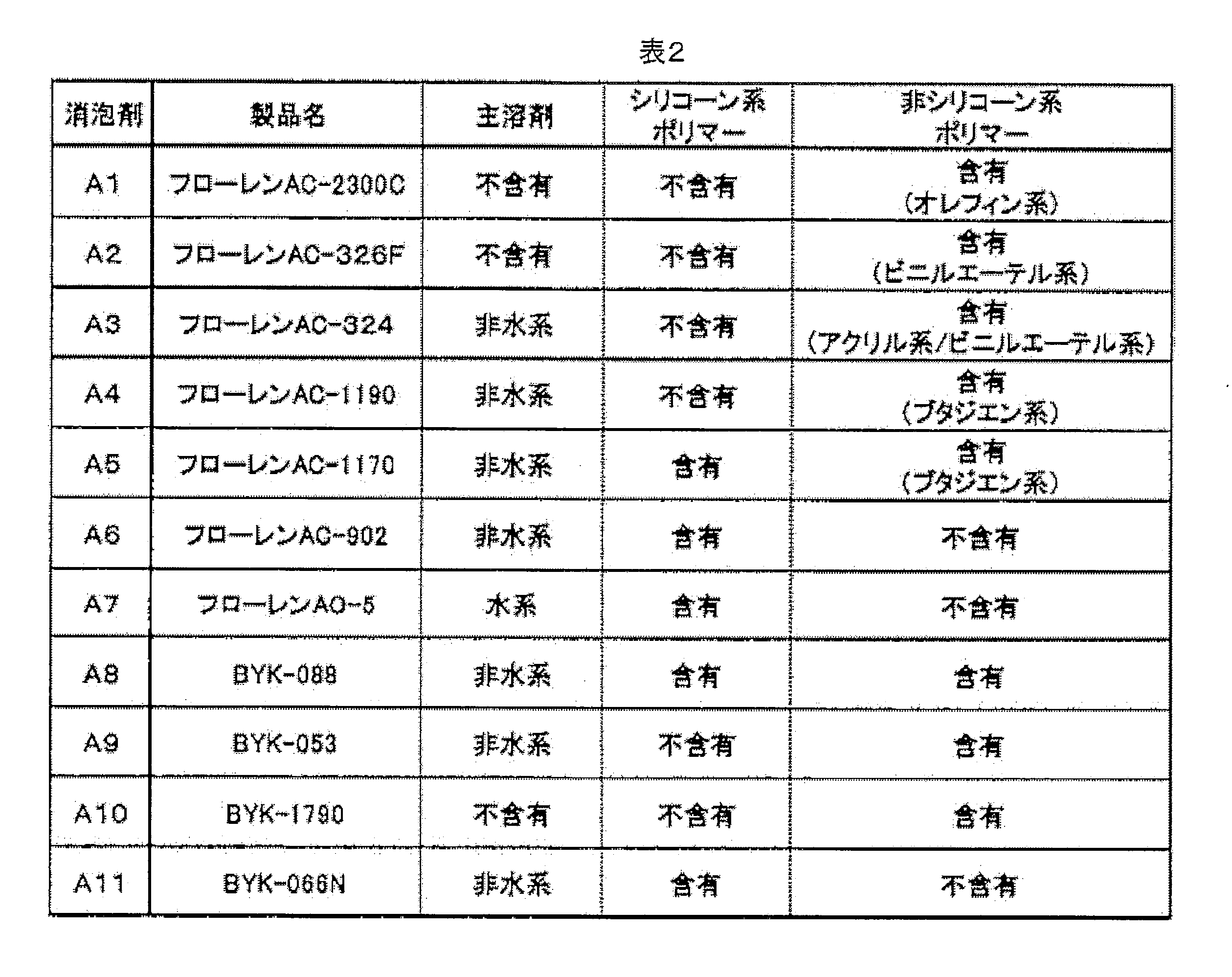
[規則26に基づく補充 27.09.2017]
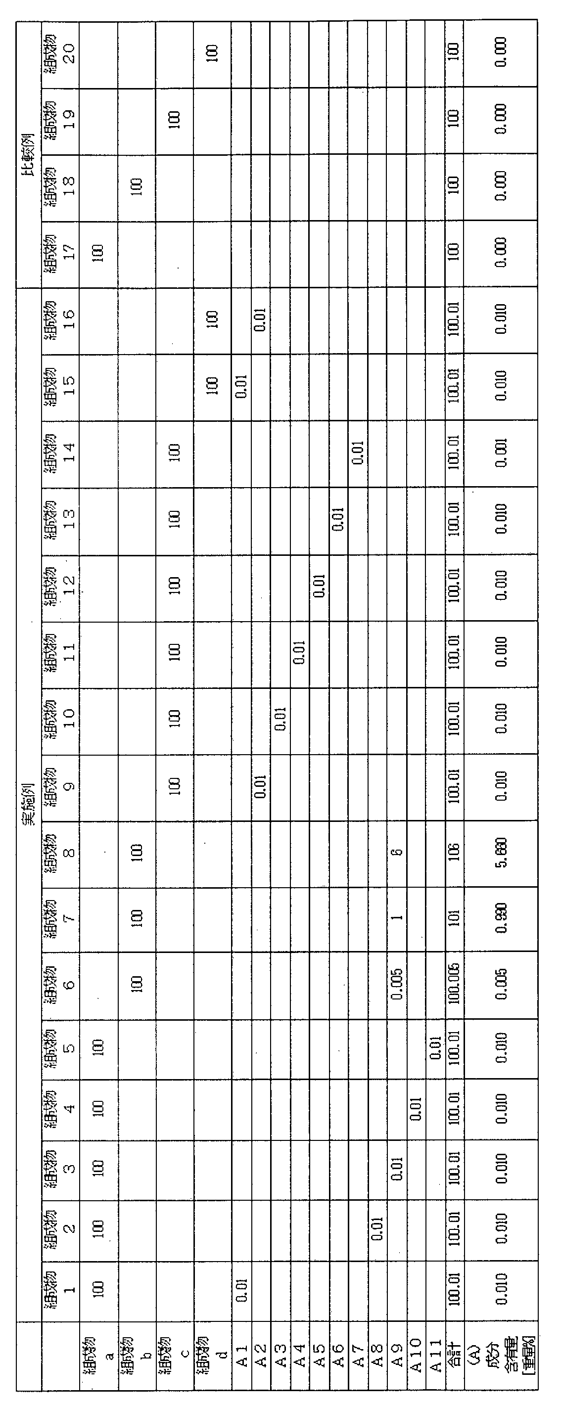
得られた本発明の組成物1~20を用いて以下評価を行った。
(表面張力測定)25℃/45%RH環境で、自動表面張力計CBVP-Z(協和界面科学製)を用いて測定した。測定結果を表4に示す。
(消泡性)表3の記載の組成物を配合し、配合後25℃環境で1週間保管した。保管後、樹脂組成物を保管場所から取り出し、ディスパー (攪拌機:新東化学(株)製 スリーワンモーター BL300、攪拌翼: 幅x横x縦 1cmx10cm x10cm)で200rpm、30分間撹拌させて組成物中に多量の気泡を混入させた。その後、内径78mmの300mLビーカーに上記にて得られた組成物を100g入れ、ビーカーを釣鐘式減圧脱泡器に入れ、内圧を500Paの減圧環境下で液内、液面の目視可能なすべての気泡が消失するまでの時間を測定した。結果を表4に示す。
◎:ビーカーから組成物があふれずに、減圧開始から5分以下に全ての気泡が消失した。
〇:ビーカーから組成物があふれずに、減圧開始から5分を超え、15分以下に全ての気泡が消失した。
△:ビーカーから組成物があふれずに、減圧開始から15分を超え、30分以下に全ての気泡が消失した。
×:ビーカーから組成物があふれた。又は、減圧開始から30分を超えて経過後も組成物内部に気泡が残存していた。
◎:ビーカーから組成物があふれずに、減圧開始から5分以下に全ての気泡が消失した。
〇:ビーカーから組成物があふれずに、減圧開始から5分を超え、15分以下に全ての気泡が消失した。
△:ビーカーから組成物があふれずに、減圧開始から15分を超え、30分以下に全ての気泡が消失した。
×:ビーカーから組成物があふれた。又は、減圧開始から30分を超えて経過後も組成物内部に気泡が残存していた。
(塗布性)10cm×10cmサイズのガラス基板に膜厚200μm、8cm×8cmの面積になるように組成物を塗布した。塗布後、平坦な場所に10分間静置し、塗布された組成物の状態を目視にて確認した。結果を表4に示す。
〇:組成物が塗布された面の各4辺が8.4cm未満。
△:組成物が塗布された面のいずれか1辺以上が8.4cm以上。
×:組成物が塗布された面のいずれか1辺以上が8.4cm以上であり、且つ、塗布面が凸凹状に荒れてしまった。
〇:組成物が塗布された面の各4辺が8.4cm未満。
△:組成物が塗布された面のいずれか1辺以上が8.4cm以上。
×:組成物が塗布された面のいずれか1辺以上が8.4cm以上であり、且つ、塗布面が凸凹状に荒れてしまった。
(硬化性)厚さ1mmのスライドガラスを用意し、膜厚が200μmとなるように組成物1~20を塗布し、その塗布面に高圧水銀灯(80W/cm、オゾンレス/IRカットフィルター付き)で積算光量100mJ/cm2の紫外線を該組成物に照射した後、該組成物の状態を確認した。評価結果を表4に示す。
〇:流動性がない
×:硬化が不十分で流動性がある
〇:流動性がない
×:硬化が不十分で流動性がある
[規則26に基づく補充 27.09.2017]

以上の結果より、本発明の紫外線硬化型接着剤組成物および製造方法は、樹脂内部に気泡が残りにくく、塗布性にも優れ、さらに硬化性が良好であることが分かる。
さらに、得られた本発明の組成物1、組成物9を用いて以下評価を行った。
(気泡混入検査)
組成物1~20について、ディスパーで200rpm、30分間撹拌させて組成物中に多量の気泡を混入させた。その後、内径78mmの300mLビーカーに上記にて得られた組成物を100g入れ、ビーカーを釣鐘式減圧脱泡器に入れ、内圧を500Paの減圧環境下で10分間静置し、減圧処理後の組成物を得た。フッ素系離型剤を塗布した厚さ1mmのスライドガラス2枚を用意し、そのうち1枚の離型剤塗布面に、減圧処理後の組成物を縦・横=30mm・30mmの面積に膜厚が200μmとなるよう塗布した。塗布後1分以内に、2枚のスライドガラスを、それぞれの離型剤塗布面が互いに向かい合うように貼り合わせた。ガラス越しに高圧水銀灯(80W/cm、オゾンレス)で積算光量2000mJ/cm2の紫外線を該樹脂組成物に照射し、該樹脂組成物を硬化させた。その後、2枚のスライドガラスを剥離し、膜比重測定用の硬化物を作製した。このように作成したサンプルを10枚作成し、10枚中の樹脂中に存在する気泡の混入割合を目視で検査した。組成物1~4、7~9、15~16については目視できる気泡混入は0枚であった。組成物6、10~12については目視できる気泡混入は1~3枚であった。組成物5、13、14については目視できる気泡混入は4~5枚であった。組成物17~20については目視できる気泡混入は5枚を超えていた。
組成物1~20について、ディスパーで200rpm、30分間撹拌させて組成物中に多量の気泡を混入させた。その後、内径78mmの300mLビーカーに上記にて得られた組成物を100g入れ、ビーカーを釣鐘式減圧脱泡器に入れ、内圧を500Paの減圧環境下で10分間静置し、減圧処理後の組成物を得た。フッ素系離型剤を塗布した厚さ1mmのスライドガラス2枚を用意し、そのうち1枚の離型剤塗布面に、減圧処理後の組成物を縦・横=30mm・30mmの面積に膜厚が200μmとなるよう塗布した。塗布後1分以内に、2枚のスライドガラスを、それぞれの離型剤塗布面が互いに向かい合うように貼り合わせた。ガラス越しに高圧水銀灯(80W/cm、オゾンレス)で積算光量2000mJ/cm2の紫外線を該樹脂組成物に照射し、該樹脂組成物を硬化させた。その後、2枚のスライドガラスを剥離し、膜比重測定用の硬化物を作製した。このように作成したサンプルを10枚作成し、10枚中の樹脂中に存在する気泡の混入割合を目視で検査した。組成物1~4、7~9、15~16については目視できる気泡混入は0枚であった。組成物6、10~12については目視できる気泡混入は1~3枚であった。組成物5、13、14については目視できる気泡混入は4~5枚であった。組成物17~20については目視できる気泡混入は5枚を超えていた。
(硬化収縮率)
フッ素系離型剤を塗布した厚さ1mmのスライドガラス2枚を用意し、そのうち1枚の離型剤塗布面に、組成物を膜厚が200μmとなるよう塗布した。その語、2枚のスライドガラスを、それぞれの離型剤塗布面が互いに向かい合うように貼り合わせた。ガラス越しに高圧水銀灯(80W/cm、オゾンレス)で積算光量2000mJ/cm2の紫外線を該樹脂組成物に照射し、該樹脂組成物を硬化させた。その後、2枚のスライドガラスを剥離し、膜比重測定用の硬化物を作製した。JIS K7112 B法に準拠し、硬化物の比重(DS)を測定した。また、25℃で樹脂組成物の液比重(DL)を測定した。DS及びDLの測定結果から、次式より硬化収縮率を算出したところ、5.0%未満であった。
硬化収縮率(%)=(DS-DL)÷DS×100
フッ素系離型剤を塗布した厚さ1mmのスライドガラス2枚を用意し、そのうち1枚の離型剤塗布面に、組成物を膜厚が200μmとなるよう塗布した。その語、2枚のスライドガラスを、それぞれの離型剤塗布面が互いに向かい合うように貼り合わせた。ガラス越しに高圧水銀灯(80W/cm、オゾンレス)で積算光量2000mJ/cm2の紫外線を該樹脂組成物に照射し、該樹脂組成物を硬化させた。その後、2枚のスライドガラスを剥離し、膜比重測定用の硬化物を作製した。JIS K7112 B法に準拠し、硬化物の比重(DS)を測定した。また、25℃で樹脂組成物の液比重(DL)を測定した。DS及びDLの測定結果から、次式より硬化収縮率を算出したところ、5.0%未満であった。
硬化収縮率(%)=(DS-DL)÷DS×100
(耐熱、耐湿接着性)
厚さ0.8mmのスライドガラスと厚さ0.8mmのアクリル板を用意し、一方に得られた組成物を膜厚が200μmとなるように塗布した後、その塗布面に他方を貼り合わせた。ガラス越しに、高圧水銀灯(80W/cm、オゾンレス)で積算光量2000mJ/cm2の紫外線を該樹脂組成物に照射し、該樹脂組成物を硬化させ、接着性評価用サンプルを作製した。これを、85℃、85%RH環境下、250時間放置した。その評価用サンプルにおいて、目視にてスライドガラス又はアクリル板の樹脂硬化物からの剥がれを確認したが、剥がれはなかった。
厚さ0.8mmのスライドガラスと厚さ0.8mmのアクリル板を用意し、一方に得られた組成物を膜厚が200μmとなるように塗布した後、その塗布面に他方を貼り合わせた。ガラス越しに、高圧水銀灯(80W/cm、オゾンレス)で積算光量2000mJ/cm2の紫外線を該樹脂組成物に照射し、該樹脂組成物を硬化させ、接着性評価用サンプルを作製した。これを、85℃、85%RH環境下、250時間放置した。その評価用サンプルにおいて、目視にてスライドガラス又はアクリル板の樹脂硬化物からの剥がれを確認したが、剥がれはなかった。
(透明性)
フッ素系離型剤を塗布した厚さ1mmのスライドガラス2枚を用意し、そのうちの1枚の離型剤塗布面に、得られた組成物を硬化後の膜厚が200μmとなるように塗布した。その後、2枚のスライドガラスを、それぞれの離型剤塗布面が互いに向かい合うように貼り合わせた。ガラス越しに高圧水銀灯(80W/cm、オゾンレス)で積算光量2000mJ/cm2の紫外線照射し、該樹脂組成物を硬化させた。その後、2枚のスライドガラスを剥離し、透明性測定用の硬化物を作製した。得られた硬化物の透明性については、分光光度計(U-3310、日立ハイテクノロジーズ(株))を用いて、400~800nm及び400~450nmの波長領域における透過率を測定した。その結果、400~800nmの透過率90%以上であり、かつ、400~450nmの透過率が90%以上であった。
フッ素系離型剤を塗布した厚さ1mmのスライドガラス2枚を用意し、そのうちの1枚の離型剤塗布面に、得られた組成物を硬化後の膜厚が200μmとなるように塗布した。その後、2枚のスライドガラスを、それぞれの離型剤塗布面が互いに向かい合うように貼り合わせた。ガラス越しに高圧水銀灯(80W/cm、オゾンレス)で積算光量2000mJ/cm2の紫外線照射し、該樹脂組成物を硬化させた。その後、2枚のスライドガラスを剥離し、透明性測定用の硬化物を作製した。得られた硬化物の透明性については、分光光度計(U-3310、日立ハイテクノロジーズ(株))を用いて、400~800nm及び400~450nmの波長領域における透過率を測定した。その結果、400~800nmの透過率90%以上であり、かつ、400~450nmの透過率が90%以上であった。
(遮光部下の樹脂の硬化性)
面積が3.5インチの液晶表示ユニットの表示面及び外周部に遮光部(幅5mm)を有する透明基板上の遮光部が形成されている面に、組成物をそれぞれの基板に膜厚が125μmとなるように塗布した。ついで、得られた塗布層に無電極紫外線ランプ(ヘレウス・ノーブルライト・フュージョン・ユーブイ社製、Dバルブ)を用いて、320nm以下の波長を遮る紫外線カットフィルター越しに、大気側から積算光量100mJ/cm2の紫外線照射を行い、硬化部分と大気側に存在する未硬化部分を有する硬化物層を形成した。尚、この時組成物に照射された紫外線は、320nm~450nmの範囲での最大照度を100とした時、200~320nmの範囲での最大照度の比率は3であった。
その後、未硬化部分が対向する形で液晶表示ユニットと遮光部を有する透明基板を貼り合せた。最後に、超高圧水銀ランプ(TOSCURE752、ハリソン東芝ライティング社製)で、遮光部を有するガラス基板側から積算光量2000mJ/cm2の紫外線を照射することにより樹脂硬化物層を硬化させ、光学部材を作製した。得られた光学部材から透明基板を外して遮光部分の樹脂硬化物層をヘプタンで洗い流した後、硬化状態を確認した。未硬化の樹脂組成物が除去された形跡は無く、遮光部の樹脂は十分硬化していた。
面積が3.5インチの液晶表示ユニットの表示面及び外周部に遮光部(幅5mm)を有する透明基板上の遮光部が形成されている面に、組成物をそれぞれの基板に膜厚が125μmとなるように塗布した。ついで、得られた塗布層に無電極紫外線ランプ(ヘレウス・ノーブルライト・フュージョン・ユーブイ社製、Dバルブ)を用いて、320nm以下の波長を遮る紫外線カットフィルター越しに、大気側から積算光量100mJ/cm2の紫外線照射を行い、硬化部分と大気側に存在する未硬化部分を有する硬化物層を形成した。尚、この時組成物に照射された紫外線は、320nm~450nmの範囲での最大照度を100とした時、200~320nmの範囲での最大照度の比率は3であった。
その後、未硬化部分が対向する形で液晶表示ユニットと遮光部を有する透明基板を貼り合せた。最後に、超高圧水銀ランプ(TOSCURE752、ハリソン東芝ライティング社製)で、遮光部を有するガラス基板側から積算光量2000mJ/cm2の紫外線を照射することにより樹脂硬化物層を硬化させ、光学部材を作製した。得られた光学部材から透明基板を外して遮光部分の樹脂硬化物層をヘプタンで洗い流した後、硬化状態を確認した。未硬化の樹脂組成物が除去された形跡は無く、遮光部の樹脂は十分硬化していた。
Claims (12)
- タッチパネル用樹脂組成物であって、25℃の環境下で樹脂組成物を容器に入れ、ディスパーで200rpm、30分間撹拌させて気泡を混入させた後、容器を減圧脱泡器に入れて内圧を500Paの減圧環境下で100μm以上の気泡が消失するまでの時間が30分以下であることを特徴とするタッチパネル用紫外線硬化型接着剤組成物。
- 少なくとも2つの光学基材を貼り合わせるために用いる樹脂組成物であって、消泡剤(A)、光重合性オリゴマー(B)、光重合性モノマー(C)、光重合開始剤(D)を含むことを特徴とする請求項1に記載のタッチパネル用紫外線硬化型接着剤組成物。
- 光重合性オリゴマー(B)が、ウレタン(メタ)アクリレート、ポリプロピレン、ポリブタジエン、水添ポリブタジエン、ポリイソプレン及び水添ポリイソプレンからなる群から選ばれる少なくとも1種の骨格をもつ(メタ)アクリレートであることを特徴とする請求項1又は2に記載のタッチパネル用紫外線硬化型接着剤組成物。
- 光重合性オリゴマー(B)が、ポリプロピレン、ポリブタジエン、水添ポリブタジエン、ポリイソプレン及び水添ポリイソプレンからなる群から選ばれる少なくとも1種の骨格をもつウレタン(メタ)アクリレートであることを特徴とする請求項1~3のいずれか一項に記載のタッチパネル用紫外線硬化型接着剤組成物。
- 消泡剤(A)の含有量が0.001~5重量%の範囲であることを特徴とする請求項1~4のいずれか一項に記載のタッチパネル用紫外線硬化型接着剤組成物。
- さらに、柔軟化成分(E)を含むことを特徴とする請求項1~5のいずれか一項に記載のタッチパネル用紫外線硬化型接着剤組成物。
- 柔軟化成分(E)として、ヒドロキシル基含有ポリマー、テルペン系樹脂、水添テルペン系樹脂、ロジン系樹脂及び水添ロジン系樹脂からなる群から選ばれる少なくとも1種を含有することを特徴とする請求項6に記載のタッチパネル用紫外線硬化型接着剤組成物。
- 樹脂組成物の表面張力が20mN/m以上であることを特徴とする請求項1~7のいずれか一項に記載のタッチパネル用紫外線硬化型接着剤組成物。
- 消泡剤(A)が非シリコン系ポリマーを含有することを特徴とする請求項1~8のいずれか一項に記載のタッチパネル用紫外線硬化型接着剤組成物。
- 下記工程1~2を有する少なくとも2つの光学基材が貼りあわされた光学部材の製造方法。
(工程1)少なくとも一つの光学基材に対して、請求項1~9のいずれか一項に記載のタッチパネル用紫外線硬化型接着剤組成物を塗布して、塗布層を形成し、該塗布層に紫外線を照射することにより硬化物層を有する光学基材を得る工程
(工程2)工程1で得られた光学基材の硬化物層に対して、他の光学基材を貼り合わせるか、又は、工程1により得られた他の光学基材の硬化物層を貼り合わせる工程 - 請求項1~9のいずれか一項に記載の紫外線硬化型接着剤組成物に活性エネルギー線を照射して得られる硬化物。
- 請求項1~9のいずれか一項に記載の紫外線硬化型接着剤組成物を用いてなることを特徴とするタッチパネル。
Priority Applications (1)
| Application Number | Priority Date | Filing Date | Title |
|---|---|---|---|
| PCT/JP2017/026561 WO2019016963A1 (ja) | 2017-07-21 | 2017-07-21 | 紫外線硬化型接着剤、それを用いた貼り合せ方法及び物品 |
Applications Claiming Priority (1)
| Application Number | Priority Date | Filing Date | Title |
|---|---|---|---|
| PCT/JP2017/026561 WO2019016963A1 (ja) | 2017-07-21 | 2017-07-21 | 紫外線硬化型接着剤、それを用いた貼り合せ方法及び物品 |
Publications (1)
| Publication Number | Publication Date |
|---|---|
| WO2019016963A1 true WO2019016963A1 (ja) | 2019-01-24 |
Family
ID=65015104
Family Applications (1)
| Application Number | Title | Priority Date | Filing Date |
|---|---|---|---|
| PCT/JP2017/026561 Ceased WO2019016963A1 (ja) | 2017-07-21 | 2017-07-21 | 紫外線硬化型接着剤、それを用いた貼り合せ方法及び物品 |
Country Status (1)
| Country | Link |
|---|---|
| WO (1) | WO2019016963A1 (ja) |
Cited By (3)
| Publication number | Priority date | Publication date | Assignee | Title |
|---|---|---|---|---|
| CN110534026A (zh) * | 2019-09-30 | 2019-12-03 | 京东方科技集团股份有限公司 | 用于3d曲面贴合脱泡的载具 |
| JP2023119086A (ja) * | 2022-02-16 | 2023-08-28 | アイカ工業株式会社 | 光硬化型接着剤組成物 |
| CN116855218A (zh) * | 2023-07-10 | 2023-10-10 | 上海森克电子科技有限公司 | 一种电容屏和液晶膜组零贴合的工艺 |
Citations (8)
| Publication number | Priority date | Publication date | Assignee | Title |
|---|---|---|---|---|
| JP2001187870A (ja) * | 1999-12-28 | 2001-07-10 | Toppan Forms Co Ltd | Uv硬化型感圧接着剤 |
| JP2005530024A (ja) * | 2002-06-19 | 2005-10-06 | スリーエム イノベイティブ プロパティズ カンパニー | 放射線硬化性、無溶剤型および印刷可能な感圧接着剤前駆物質 |
| JP2015520787A (ja) * | 2012-05-22 | 2015-07-23 | ヘンケル ユーエス アイピー エルエルシー | 光学的に透明な光硬化性液状接着剤 |
| WO2015119245A1 (ja) * | 2014-02-10 | 2015-08-13 | 日本化薬株式会社 | タッチパネル用紫外線硬化型接着剤組成物、それを用いた光学部材の製造方法、硬化物及びタッチパネル |
| JP2015165014A (ja) * | 2014-02-06 | 2015-09-17 | 荒川化学工業株式会社 | 光学用紫外線硬化型接着剤組成物、該硬化層および光学部材 |
| JP2015189961A (ja) * | 2014-03-29 | 2015-11-02 | 株式会社日本触媒 | 高エネルギー可視光線遮蔽性粘着剤 |
| JP2015209520A (ja) * | 2014-04-30 | 2015-11-24 | 荒川化学工業株式会社 | 光学用紫外線硬化型接着剤組成物、該硬化層および光学部材 |
| WO2016024492A1 (ja) * | 2014-08-12 | 2016-02-18 | 横浜ゴム株式会社 | 紫外線硬化性樹脂組成物及びこれを用いる積層体 |
-
2017
- 2017-07-21 WO PCT/JP2017/026561 patent/WO2019016963A1/ja not_active Ceased
Patent Citations (8)
| Publication number | Priority date | Publication date | Assignee | Title |
|---|---|---|---|---|
| JP2001187870A (ja) * | 1999-12-28 | 2001-07-10 | Toppan Forms Co Ltd | Uv硬化型感圧接着剤 |
| JP2005530024A (ja) * | 2002-06-19 | 2005-10-06 | スリーエム イノベイティブ プロパティズ カンパニー | 放射線硬化性、無溶剤型および印刷可能な感圧接着剤前駆物質 |
| JP2015520787A (ja) * | 2012-05-22 | 2015-07-23 | ヘンケル ユーエス アイピー エルエルシー | 光学的に透明な光硬化性液状接着剤 |
| JP2015165014A (ja) * | 2014-02-06 | 2015-09-17 | 荒川化学工業株式会社 | 光学用紫外線硬化型接着剤組成物、該硬化層および光学部材 |
| WO2015119245A1 (ja) * | 2014-02-10 | 2015-08-13 | 日本化薬株式会社 | タッチパネル用紫外線硬化型接着剤組成物、それを用いた光学部材の製造方法、硬化物及びタッチパネル |
| JP2015189961A (ja) * | 2014-03-29 | 2015-11-02 | 株式会社日本触媒 | 高エネルギー可視光線遮蔽性粘着剤 |
| JP2015209520A (ja) * | 2014-04-30 | 2015-11-24 | 荒川化学工業株式会社 | 光学用紫外線硬化型接着剤組成物、該硬化層および光学部材 |
| WO2016024492A1 (ja) * | 2014-08-12 | 2016-02-18 | 横浜ゴム株式会社 | 紫外線硬化性樹脂組成物及びこれを用いる積層体 |
Cited By (5)
| Publication number | Priority date | Publication date | Assignee | Title |
|---|---|---|---|---|
| CN110534026A (zh) * | 2019-09-30 | 2019-12-03 | 京东方科技集团股份有限公司 | 用于3d曲面贴合脱泡的载具 |
| JP2023119086A (ja) * | 2022-02-16 | 2023-08-28 | アイカ工業株式会社 | 光硬化型接着剤組成物 |
| JP7851142B2 (ja) | 2022-02-16 | 2026-04-24 | アイカ工業株式会社 | 光硬化型接着剤組成物 |
| CN116855218A (zh) * | 2023-07-10 | 2023-10-10 | 上海森克电子科技有限公司 | 一种电容屏和液晶膜组零贴合的工艺 |
| CN116855218B (zh) * | 2023-07-10 | 2024-01-30 | 上海森克电子科技有限公司 | 一种电容屏和液晶膜组零贴合的工艺 |
Similar Documents
| Publication | Publication Date | Title |
|---|---|---|
| JP6568567B2 (ja) | 紫外線硬化型樹脂組成物 | |
| JP5331271B1 (ja) | 光学部材の製造方法及びそのための紫外線硬化型樹脂組成物の使用 | |
| WO2015119245A1 (ja) | タッチパネル用紫外線硬化型接着剤組成物、それを用いた光学部材の製造方法、硬化物及びタッチパネル | |
| JP6778106B2 (ja) | タッチパネル用紫外線硬化型樹脂組成物、それを用いた貼り合せ方法及び物品 | |
| JP6620092B2 (ja) | タッチパネル用紫外線硬化型樹脂組成物、それを用いた貼り合せ方法及び物品 | |
| WO2019069872A1 (ja) | 紫外線硬化型接着剤組成物、その硬化物および紫外線硬化型接着剤組成物を用いた光学部材の製造方法 | |
| JPWO2015190561A1 (ja) | タッチパネル用紫外線硬化型樹脂組成物、それを用いた貼り合せ方法及び物品 | |
| WO2015199156A1 (ja) | 光学部材の製造方法及びそれに用いる紫外線硬化型樹脂組成物 | |
| JP6378184B2 (ja) | 光学部材の製造方法及びそれに用いる紫外線硬化型樹脂組成物 | |
| WO2016117526A1 (ja) | 画像表示装置の製造方法、それに用いる硬化性樹脂組成物、タッチパネル及び画像表示装置 | |
| WO2015190571A1 (ja) | タッチパネル用紫外線硬化型樹脂組成物、それを用いた貼り合せ方法及び物品 | |
| WO2016021517A1 (ja) | 光学部材の製造方法及びそれに用いる硬化性樹脂組成物 | |
| WO2019093157A1 (ja) | 紫外線硬化型接着剤組成物、その硬化物および紫外線硬化型接着剤組成物を用いた光学部材の製造方法 | |
| JP2018012750A (ja) | 紫外線硬化型接着剤、それを用いた貼り合せ方法及び物品 | |
| WO2017073584A1 (ja) | タッチパネル用紫外線硬化型樹脂組成物、それを用いた硬化物及びタッチパネル |
Legal Events
| Date | Code | Title | Description |
|---|---|---|---|
| 121 | Ep: the epo has been informed by wipo that ep was designated in this application |
Ref document number: 17918302 Country of ref document: EP Kind code of ref document: A1 |
|
| NENP | Non-entry into the national phase |
Ref country code: DE |
|
| 122 | Ep: pct application non-entry in european phase |
Ref document number: 17918302 Country of ref document: EP Kind code of ref document: A1 |
|
| NENP | Non-entry into the national phase |
Ref country code: JP |