WO2019016933A1 - 対基板作業システム - Google Patents
対基板作業システム Download PDFInfo
- Publication number
- WO2019016933A1 WO2019016933A1 PCT/JP2017/026416 JP2017026416W WO2019016933A1 WO 2019016933 A1 WO2019016933 A1 WO 2019016933A1 JP 2017026416 W JP2017026416 W JP 2017026416W WO 2019016933 A1 WO2019016933 A1 WO 2019016933A1
- Authority
- WO
- WIPO (PCT)
- Prior art keywords
- substrate
- cover
- opening
- slide cover
- board
- Prior art date
- Legal status (The legal status is an assumption and is not a legal conclusion. Google has not performed a legal analysis and makes no representation as to the accuracy of the status listed.)
- Ceased
Links
Images



Classifications
-
- H—ELECTRICITY
- H05—ELECTRIC TECHNIQUES NOT OTHERWISE PROVIDED FOR
- H05K—PRINTED CIRCUITS; CASINGS OR CONSTRUCTIONAL DETAILS OF ELECTRIC APPARATUS; MANUFACTURE OF ASSEMBLAGES OF ELECTRICAL COMPONENTS
- H05K13/00—Apparatus or processes specially adapted for manufacturing or adjusting assemblages of electric components
- H05K13/04—Mounting of components, e.g. of leadless components
Definitions
- the present invention relates to a substrate handling system.
- Patent Document 1 a plurality of substrate-to-substrate working modules provided with an opening on the side surface are arranged on the upper surface of the base, and each substrate-to-substrate working module is drawably installed relative to the base A working system is disclosed.
- the operator pulls out one of the two adjacent substrate working modules to the front, and shifts the front and back positions of the two substrate operating modules, when performing maintenance and the like of the substrate working module. . Thereby, the worker can expose the opening and can access the inside of the substrate working module from the opening.
- the present specification aims to provide a substrate handling system in which the inside of a substrate handling module can be easily accessed while securing safety.
- the present specification is arranged on one or more bases and the upper surface of the base, and is provided so as to be extractable in a direction perpendicular to the arrangement direction with respect to the base, and carries in and out the substrate in the arrangement direction.
- the substrate-to-board operation system of the present disclosure includes the slide cover capable of opening and closing the opening, closing the opening allows the opening to be exposed while securing safety when performing production on a substrate. Easy access to the inside of the board work module.
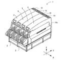
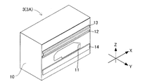
- FIG. 1 is a perspective view of a substrate handling system in accordance with an embodiment of the present specification. It is a figure which shows the internal structure of a board
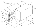
- FIG. 18 is a perspective view of two base-to-board working modules arranged on the top of one base and one base as viewed from the rear side, wherein one of the two base-to-board working modules is front The opening part of the other board
- substrate working module is drawn out by FIG. It is the perspective view which looked at two base-to-board working modules arranged on the upper surface of one base and one base seen from the front side, and one of the two base-to-board working modules is the front. The state drawn out is schematically shown. It is a perspective view of a slide cover.
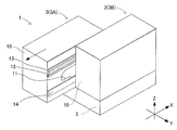
- FIG. 18 is a perspective view of two base-to-board working modules arranged on the upper surface of one base and one base as viewed from the rear side, one of the two board-to-board working modules being fronted And the slide cover is slid forward.
- the left-right direction of the substrate working system 1 is defined as the X direction, the front-rear direction orthogonal to the X direction as the Y direction, and the vertical direction as the Z direction.
- the substrate processing system 1 mainly includes a base 2 and a plurality of substrate processing modules 3. On the upper surface of the base 2, a plurality of substrate-to-substrate working modules 3 are arranged in the left-right direction, and each substrate-to-substrate working module 3 is provided to be able to be pulled forward with respect to the base 2.
- the substrate working system 1 may be configured by one unit capable of installing four unit-to-substrate work modules 3 or may be configured by arranging four bases 2 on which one unit-to-substrate operation module 3 can be arranged.
- the substrate-to-substrate working module 3 mainly includes a housing 10, a substrate transfer device 20, a component supply device 30, a component transfer device 40, and a control device 50.
- the housing 10 is formed in a box shape that can accommodate the substrate transfer device 20 and the component transfer device 40.
- substrate K is formed in the both sides
- the outer shape of the opening 11 is set to a size larger than the outer size required for carrying in and out the substrate K. For example, when the operator performs maintenance of the substrate working module 3, the opening The inside of the housing 10 can be accessed from the unit 11.
- the side surfaces of the four substrate-to-substrate work modules 3 constituting the substrate-to-substrate work system 1 shown in FIG. 1 the side surfaces not facing the other substrate-to-substrate work modules 3 (side surfaces facing outward in the arrangement direction)
- the opening 11 formed in the opening 11 is closed by the cover member 10 a except for a portion required to carry the substrate K in and out.
- the substrate transfer apparatus 20 is configured by a belt conveyor or the like, and sequentially transfers the substrate K carried into the housing 10 from the opening 11 in the X direction.
- the substrate transfer apparatus 20 positions the substrate K at a predetermined position inside the housing 10. Then, when the mounting process of the component on the positioned substrate K is completed, the substrate transfer apparatus 20 carries the substrate K out of the opening 11 to the outside of the housing 10.
- the component supply device 30 supplies components to be mounted on the substrate K.
- the component supply device 30 includes a plurality of slots arranged in the X direction, and a feeder 31 is detachably set in each of the plurality of slots.
- the component feeding device 30 feeds and moves the carrier tape by the feeder 31 and feeds components to the tip end side (upper side in FIG. 1) of the feeder 31.
- the component transfer device 40 holds the component supplied by the component supply device 30, and mounts the held component on the positioned substrate K.
- the component transfer device 40 mainly includes a head drive device 41, a moving table 42, and a mounting head 43.
- the head drive device 41 is configured to be able to move the movable table 42 in the X direction and the Y direction by a linear movement mechanism.
- the mounting head 43 is a holding device that holds components, and is configured to be removable from the moving table 42. Further, in the nozzle holder 44 provided in the mounting head 43, a plurality of suction nozzles (not shown) capable of holding components are detachably provided.
- the control device 50 mainly includes a CPU, various memories, and a control circuit.
- the control device 50 performs a control program for operating the substrate work module 3 and a control for performing a process of mounting components on the substrate K.
- the substrate-to-substrate operation system 1 further includes a slide cover 70 and a cover fixing portion 80.
- the slide cover 70 is a plate-like member disposed between two adjacent pair of substrate working modules 3 and is provided slidably with respect to each of the two pair of substrate working modules 3.
- the cover fixing portion 80 is a columnar member fixed to the rear end of the base 2.
- the slide cover 70 is configured such that the rear side of the slide cover 70 can be connected to the cover fixing portion 80 by a bolt.
- the slide cover 70 is coupled to the cover fixing portion 80 to restrict the slide with respect to the base 2.
- the slide cover 70 can be slid relative to the base 2 by releasing the connection with the cover fixing portion 80 by a bolt and removing it from the cover fixing portion 80.
- the slide cover 70 may be releasably connected to the cover fixing portion 80, and may be connected to the cover fixing portion 80 by a method other than bolt connection.
- the slide cover 70 includes a cover main body 71, a substrate transfer port 72, a pair of extending portions 73, and a cutout portion 74.
- the cover main body 71 is formed in an outer shape larger than the opening 11, and the opening 11 is closed by arranging the cover main body 71 at a position corresponding to the opening 11.
- the substrate transfer port 72 is an opening provided for carrying in / out the substrate K with respect to the housing 10 when the opening 11 is closed by the cover main body 71.
- the substrate K transported from the adjacent substrate work module 3 adjacent on the upstream side (upper left side in FIG. 1) in the transport direction of the substrate K (arrangement direction of the substrate work module 3) faces the upstream side in the transport direction of the substrate K It is carried into the inside of the housing 10 from the substrate transfer port 72. Further, the substrate K carried into the inside of the housing 10 from the substrate conveyance port 72 facing the downstream side (the lower right side in FIG. 1) in the conveyance direction of the substrate K after the component mounting operation is completed. It is carried out outside.
- the pair of extending portions 73 includes an upper extending portion 73 a extending rearward from the upper end portion of the cover main body 71 and a lower extending portion 73 b extending rearward from the lower end portion of the cover main body 71.
- the cover main body 71 is disposed at a position corresponding to the opening 11, and the pair of extending portions 73 and the notches 74 are positioned rearward of the opening 11.
- the worker has limited access to the inside of the housing 10 from the opening 11.
- the notch 74 is formed to be able to be disposed at a position corresponding to the opening 11 by sliding the slide cover 70. That is, the opening portion 11 is exposed from the cutout portion 74 by arranging the cutout portion 74 at a position corresponding to the opening portion 11, and the operator accesses the inside of the housing 10 from the cutout portion 74 and the opening portion 11. It is possible to do
- the slide cover 70 also includes four rolling elements 90.
- the rolling element 90 slidably supports the slide cover 70 with respect to two adjacent substrate working modules 3.
- the plurality of rolling elements 90 are provided on the upper end portion of the cover main body 71 or the upper end portion of the upper extension portion 73 a with a space in the front-rear direction.
- the rolling element 90 includes a pair of rollers 91 and a rolling shaft portion 92.
- the pair of rollers 91 is disposed on both sides of the cover main body 71 or the upper extension portion 73a.
- the rolling shaft portion 92 is penetrated through the cover main body 71 or the upper extending portion 73 a, and rotatably supports the pair of rollers 91 with respect to the cover main body 71 or the extending portion 73.
- the to-be-rolled member 12 is a long member extending in the front-rear direction, and supports the roller 91 rollably in the front-rear direction with respect to the housing 10.
- the to-be-rolled member 12 is provided with the lower fixing
- the lower fixing portion 12 a is a portion fixed to the housing 10.
- the rolling support portion 12 b is a portion extending outward in the X direction from the upper end of the lower fixing portion 12 a with respect to the housing 10, and the roller 91 rolls on the upper surface of the rolling support portion 12 b.
- a guide member 13 for guiding the roller 91 is fixed to an upper portion of a portion to which the rolled member 12 is fixed on the side surface of the housing 10.
- the guide member 13 prevents the roller 91 from coming off the roller 12.
- the guide member 13 includes an upper fixing portion 13a, an extending portion 13b, and a restricting portion 13c.
- the upper fixing portion 13 a is a portion fixed to the side surface of the housing 10.
- the extending portion 13b is a portion extending outward in the X direction from the lower end of the fixing portion 13a with respect to the housing 10, and is disposed above the roller 90 rolling on the rolling support portion 12b.
- the restricting portion 13 c is a portion extending downward from the leading end portion of the extending portion 13 b in the extending direction, and restricts the rollable range of the roller 91 rolling the member to be rolled 12.
- each of the two pair-to-substrate working modules 3 is a side surface of the housing 10 facing each other, and protrudes from the side surface of the housing 10 at a lower portion of a portion where the respective opening 11 is formed.
- a protrusion 14 is provided.
- the protruding portion 14 extends in the front-rear direction, and the lower end portion of the cover main body 71 and the lower extending portion 73 b are disposed between the facing protruding portions 14. Therefore, the substrate handling system 1 can reduce the swinging of the slide cover 70 in the left-right direction by bringing the lower end portion of the slide cover 70 swinging in the left-right direction into contact with the projecting portion 14. Further, the projecting portion 14 is embossed on the surface portion in contact with the slide cover 70.
- the slide cover 70 is provided to be able to open and close the opening 11 by sliding relative to the housing 10. Furthermore, the substrate handling system 1 arranges one slide cover 70 between the two substrate handling modules 3. Then, one slide cover 70 is slidably supported by both of the pair of substrate work modules 3 via the plurality of rolling elements 90. That is, in the substrate handling system 1, one slide cover 70 is configured to open and close the facing openings 11 of the two substrate handling modules 3. As a result, since the substrate-to-substrate working system 1 can reduce the gap required between the two substrate-to-substrate working modules 3, the installation space required for the substrate-to-substrate working system 1 can be reduced. Can.
- the slide cover 70 may be supported so as to be slidable with respect to the substrate working module 3, and the support mode of the slide cover 70 with respect to the substrate working module 3 is a plurality of rolling elements as in the present embodiment. It is not limited to the aspect slidably supported by the substrate working module 3 via 90.
- the arrangement position of the substrate working module 3 that is, the arrangement position of the substrate working module 3 in a state where it is not pulled forward with respect to the base 2
- All rolling elements 90 provided on the slide cover 70 are supported so as to be able to roll on the rolling members 12 of the substrate working module 3 in the state where the substrate working module 3 is arranged at the reference position. .
- cover main body 71 is arranged at a position corresponding to opening 11 of board-to-substrate working module 3 arranged at the reference position. It will be in the state closed by 71.
- the gap formed between the two adjacent substrate-to-board operation modules 3 is reduced to save the installation space. Therefore, the operator can not access the inside of the housing 10 from the opening 11 with the adjacent board-to-board working modules 3 arranged at the same position in the front-rear direction. Therefore, when accessing the inside of the housing 10, the worker pulls out one of the two adjacent substrate working modules 3 to the front. As a result, the operator can shift the front and back positions of the two adjacent substrate working modules 3.
- first pair of substrate working modules 3A one of the two adjacent substrate working modules 3 to be drawn forward is referred to as a "first pair of substrate working modules 3A", and the other one located behind is hereinafter described.
- the substrate-to-substrate working module 3 is referred to as a "second substrate-to-substrate working module 3B".
- the slide cover 70 is connected to the cover fixing portion 80, the slide cover 70 is restricted from sliding relative to the base 2.
- the slide cover 70 slides relative to the first pair of substrate working modules 3A.
- the second pair substrate working module 3B fixes the cover The slide cover 70 fixed to the portion 80 can keep the opening 11 covered.
- substrate working system 1 can aim at the improvement of safety.
- the substrate handling system 1 can stably support the slide cover 70 even in a state where the first pair substrate handling module 3A is pulled forward.
- the operator can slide slide cover 70 forward with respect to second substrate working module 3 B by releasing connection of slide cover 70 to cover fixing portion 80. . Then, the operator slides the slide cover 70 forward with respect to the second substrate working module 3B from the state in which the first substrate working module 3A is pulled forward, so that the operator of the second substrate working module 3B is The notch 74 can be moved to a position corresponding to the opening 11.
- the operator when the operator tries to access the inside back of the case 10 of the second substrate-to-board operation module 3B, the operator moves the slide cover 70 forward with the first pair of substrate operation module 3A pulled forward. By sliding, it is possible to easily access the inside rear of the housing 10 from the opening 11 of the exposed second substrate working module 3B.
- the rolling elements 90 moved forward of the to-be-rolled member 12 and the guide member 13 of the second board-to-board working module 3B are the first pair board working modules 3A.
- the rollable member 12 and the guide member 13 support the roll. Therefore, the substrate-to-substrate operation system 1 can stably support the slide cover 70 even in a state in which the slide cover 70 is slid forward while the first pair of substrate operation modules 3A is pulled forward. .
- the slide cover 70 is formed with an extending portion 73 extending rearward from the cover main body 71, and the plurality of rolling elements 90 are spaced in the front-rear direction with respect to the upper end portion of the cover main body 71 and the upper end portion of the upper extending portion 73a. It is provided while leaving In this case, even if the slide cover 70 is slid forward with the front and back positions of the two pair of board operation modules 3 largely shifted, the state in which the slide cover 70 is supported by the first pair of board operation modules 3A is maintained. It can be easy to do.
- the slide cover 70 is formed with a cutaway portion 74 formed by cutting out from the rear side to the front side.
- the slide amount to the front of the slide cover 70 can be made small. Therefore, even if the substrate processing module 3 is in a state in which the opening 11 of the second substrate processing module 3B is exposed, the slide cover 70 is supported on both of the two substrate processing modules 3 It can be made easy to maintain.
- the substrate-to-substrate operation system 1 includes the slide cover 70 capable of opening and closing the opening 11 formed in the housing 10 of the substrate-to-substrate operation module 3. Therefore, the substrate-to-substrate operation system 1 can easily perform access to the inside by opening the opening 11 while securing safety when performing the production for the substrate K by closing the opening 11. it can.
- each substrate-to-substrate working module 3 is independently provided with two slide covers 70, and each slide cover 70 is supported so as to be able to open and close the opening 11 for each side surface facing the arrangement direction of the housing 10. It may be
- the slide cover 70 includes the pair of extending portions 73 and the notches 74, and the notches 74 are formed between the upper extending portion 73a and the lower extending portion 73b.
- the extension portion 73 may be configured by only the upper extension portion 73a or only the lower extension portion 73b, and the extension portion 73 extends rearward from the central portion of the cover main body 71 and the extension portion
- the notch 74 may be formed above and below the portion 73.
- the slide cover 70 may be formed in a rectangular plate shape which does not include the pair of extension portions 73 and the cutout portion 74.
- the rear end portion of the cover main body 71 is detachably coupled to the cover fixing portion 80, and the cover main body 71 is formed in a size capable of closing the opening 11 in a state fixed to the cover fixing portion 80. Be done.
- the case of preventing the roller 91 from disengaging from the rolled member 12 by the guide member 13 provided above the rolled member 12 has been described. Not limited to this.
- the to-be-substrates working system 1 may be provided with a restricting portion 12 c extending upward with respect to the rolling support portion 12 b of the rolled member 12. In this case, since the guide member work system 1 can omit the guide member 13, the weight reduction of the housing 10 can be achieved.
- Substrate-to-board working system 2 Base: 3: Substrate-to-board working module: 11: Opening, 70: Slide cover, 71: Cover body, 73: Extension, 74: Notch, 80: Cover fixing, K: Substrate
Landscapes
- Engineering & Computer Science (AREA)
- Manufacturing & Machinery (AREA)
- Microelectronics & Electronic Packaging (AREA)
- Supply And Installment Of Electrical Components (AREA)
Abstract
1又は複数のベースと、ベースの上面に配列されると共に、ベースに対し配列方向に直交する方向へ引き出し可能に設けられ、且つ、配列方向に基板を搬入出するための開口部をそれぞれ備えた複数の対基板作業モジュールと、隣接する二台の対基板作業モジュールの間に、隣接する二台の対基板作業モジュールの各々に対してスライド可能に設けられ、且つ、スライドすることにより前記開口部を開閉可能なスライドカバーと、を備える対基板作業システム。
Description
本発明は、対基板作業システムに関する。
特許文献1には、側面に開口部が設けられた複数の対基板作業モジュールが、ベースの上面に配列されると共に、各々の対基板作業モジュールがベースに対して引き出し可能に設置された対基板作業システムが開示されている。作業者は、対基板作業モジュールのメンテナンス等を行う際に、隣接する二台の対基板作業モジュールのうち一方の対基板作業モジュールを前方へ引き出し、二台の対基板作業モジュールの前後位置をずらす。これにより、作業者は、開口部を露出させることができ、開口部から対基板作業モジュールの内部にアクセスすることができる。
隣接する二台の対基板作業モジュールの前後位置をずらすと、二台の対基板作業モジュールのうち前方に引き出された一方の対基板作業モジュールは、開口部の前方側が露出するのに対し、後方に位置する他方の対基板作業モジュールは、開口部の後方側が露出する。そのため、対基板作業モジュールの内部前方側へアクセスする際には、アクセスしようとする対基板作業モジュールを前方へ引き出し、対基板作業モジュールの内部後方側へアクセスする際には、アクセスしようとする対基板作業モジュールに隣接する対基板作業モジュールを前方へ引き出すことが、作業効率の点において望ましい。
この点に関して、隣接する二台の対基板作業モジュールのうち、一方の対基板作業モジュールを前方へ引き出した状態であっても、後方に位置する他方の対基板作業モジュールは、基板に対する作業を行うことができる。従って、後方に位置する対基板作業モジュールの開口部を覆うカバー等を設け、作業者の手や所持品等が開口部から対基板作業モジュールの内部に進入することを防止することが、安全を確保する観点において望ましい。
しかしながら、開口部を覆うカバーをベースに固定した場合、後方に位置する対基板作業モジュールの開口部が常に塞がれるため、作業者は、後方に位置する対基板作業モジュールの内部にアクセスすることができなくなる。よってこの場合、対基板作業モジュールの内部後方へアクセスする際に、アクセスしようとする対基板作業モジュールを前方へ引き出し、開口部の前方から手を入れて内部後方へアクセスしたり、アクセスしようとする対基板作業モジュールをベースから一旦取り外す等の作業が必要となり、対基板作業モジュールの内部にアクセスする作業が繁雑となる。
本明細書は、安全性を確保しつつ、対基板作業モジュールの内部に容易にアクセスできる対基板作業システムを提供することを目的とする。
本明細書は、1又は複数のベースと、前記ベースの上面に配列されると共に、前記ベースに対し配列方向に直交する方向へ引き出し可能に設けられ、且つ、前記配列方向に基板を搬入出するための開口部をそれぞれ備えた複数の対基板作業モジュールと、隣接する二台の前記対基板作業モジュールの間に、前記隣接する二台の前記対基板作業モジュールの各々に対してスライド可能に設けられ、且つ、スライドすることにより前記開口部を開閉可能なスライドカバーと、を備えた対基板作業システムを開示する。
本開示の対基板作業システムは、開口部を開閉可能なスライドカバーを備えているので、開口部を閉塞することにより基板に対する生産を行う際の安全性を確保しつつ、開口部を露出させることで対基板作業モジュールの内部に容易にアクセスできる。
以下、本明細書に開示する対基板作業システムを適用した実施形態について、図面を参照しながら説明する。まず、図1及び図2を参照して、一実施形態における対基板作業システム1の構成を説明する。なお、以下において、対基板作業システム1の左右方向をX方向、X方向に直交する前後方向をY方向、鉛直方向をZ方向と定義する。
図1に示すように、対基板作業システム1は、ベース2と、複数の対基板作業モジュール3とを主に備える。ベース2の上面には、複数の対基板作業モジュール3が左右方向に配列され、各々の対基板作業モジュール3は、ベース2に対して前方へ引き出し可能に設けられる。なお、本実施形態では、対基板作業システム1が、2台の対基板作業モジュール3を設置可能なベース2を2台並べて構成される場合を例に挙げて説明するが、対基板作業システム1は、4台の対基板作業モジュール3を設置可能な1台で構成されるものでもよく、1台の対基板作業モジュール3を配置可能なベース2を4台並べて構成されるものでもよい。
次に、図2を参照して、対基板作業モジュール3の概略構成を説明する。図2に示すように、対基板作業モジュール3は、筐体10と、基板搬送装置20と、部品供給装置30と、部品移載装置40と、制御装置50と、を主に備える。筐体10は、基板搬送装置20及び部品移載装置40を収容可能な箱状に形成される。また、筐体10の配列方向(左右方向)を向く両側面には、基板Kを搬入出するための開口部11が形成される。なお、開口部11の外形は、基板Kの搬入出に必要とされる外形寸法よりも大きな寸法に設定されており、作業者は、例えば、対基板作業モジュール3のメンテナンスを行う際に、開口部11から筐体10の内部へアクセスすることができる。
なお、図1に示す対基板作業システム1を構成する4台の対基板作業モジュール3の各側面のうち、他の対基板作業モジュール3に対向していない側面(配列方向における外側を向く側面)に形成される開口部11は、基板Kを搬入出するために必要とされる部分を除き、カバー部材10aにより閉塞されている。
基板搬送装置20は、ベルトコンベア等により構成され、開口部11から筐体10に搬入された基板KをX方向へ順次搬送する。基板搬送装置20は、筐体10の内部における所定位置に基板Kを位置決めする。そして、位置決めされた基板Kに対する部品の装着処理が終了すると、基板搬送装置20は、基板Kを開口部11から筐体10の外部へ搬出する。
部品供給装置30は、基板Kに装着する部品を供給する。部品供給装置30は、X方向に配列された複数のスロットを備え、それら複数のスロットの各々には、フィーダ31が着脱可能にセットされる。部品供給装置30は、フィーダ31によってキャリアテープを送り移動させ、フィーダ31の先端側(図1上側)に部品を供給する。
部品移載装置40は、部品供給装置30によって供給された部品を保持し、保持した部品を位置決めされた基板Kに装着する。部品移載装置40は、ヘッド駆動装置41と、移動台42と、装着ヘッド43とを主に備える。ヘッド駆動装置41は、直動機構により移動台42をX方向及びY方向へ移動可能に構成される。装着ヘッド43は、部品を保持する保持装置であり、移動台42に対して着脱可能に構成される。また、装着ヘッド43に設けられたノズルホルダ44には、部品を保持可能な複数の吸着ノズル(図示せず)が着脱可能に設けられる。
制御装置50は、主に、CPUや各種メモリ、制御回路により構成される。制御装置50は、対基板作業モジュール3を動作させるための制御プログラム、基板Kに対する部品の装着処理を行うための制御を行う。
また、図3及び図4に示すように、対基板作業システム1は、スライドカバー70と、カバー固定部80と、を更に備える。スライドカバー70は、隣接する二台の対基板作業モジュール3の間に配置された板状の部材であって、二台の対基板作業モジュール3の各々に対してスライド可能に設けられる。
カバー固定部80は、ベース2の後方側端部に固定された柱状の部材である。スライドカバー70は、カバー固定部80に対してスライドカバー70の後方側をボルトにより連結可能に構成される。スライドカバー70は、カバー固定部80に連結されることで、ベース2に対するスライドが規制される。一方、スライドカバー70は、ボルトによるカバー固定部80との連結を解除し、カバー固定部80から取り外されることで、ベース2に対してスライド可能となる。なお、スライドカバー70は、カバー固定部80に対して取り外し可能に連結されていればよく、ボルトによる連結以外の方法でカバー固定部80に連結されていてもよい。
次に、図5を参照して、スライドカバー70について説明する。図5に示すように、スライドカバー70は、カバー本体71と、基板搬送口72と、一対の延在部73と、切欠部74と、を備える。
カバー本体71は、開口部11よりも大きな外形に形成され、開口部11は、カバー本体71が開口部11と対応する位置に配置されることで閉塞される。基板搬送口72は、カバー本体71による開口部11の閉塞時において、筐体10に対する基板Kの搬入出を行うために設けられた開口である。基板Kの搬送方向(対基板作業モジュール3の配列方向)において上流側(図1左上側)で隣接する対基板作業モジュール3から搬送された基板Kは、基板Kの搬送方向における上流側を向く基板搬送口72から筐体10の内部に搬入される。また、筐体10の内部に搬入された基板Kは、部品の装着作業が終了した後、基板Kの搬送方向において下流側(図1右下側)を向く基板搬送口72から筐体10の外部に搬出される。
一対の延在部73は、カバー本体71の上端部分から後方へ延びる上延在部73aと、カバー本体71の下端部分から後方へ延びる下延在部73bと、を備える。スライドカバー70は、上延在部73a及び下延在部73bの少なくとも一方の後端部分をカバー固定部80に連結することにより、ベース2に対するスライドカバー70のスライドが規制される。切欠部74は、上延在部73aの下方、且つ、下延在部73bの上方に設けられ、スライドカバー70の後端部分から前方へ向けて切欠き形成される。
スライドカバー70による開口部11の閉塞時において、カバー本体71は、開口部11と対応する位置に配置され、一対の延在部73及び切欠部74は、開口部11よりも後方に位置する。このとき、作業者は、開口部11から筐体10の内部へのアクセスが制限される。一方、切欠部74は、スライドカバー70をスライドさせることにより、開口部11と対応する位置に配置可能に形成される。即ち、開口部11は、切欠部74が開口部11に対応する位置に配置されることで切欠部74から露出し、作業者は、切欠部74及び開口部11から筐体10の内部へアクセスすることが可能な状態となる。
また、スライドカバー70は、4つの転動体90を備える。転動体90は、スライドカバー70を二台の隣接する対基板作業モジュール3に対してスライド可能に支持する。複数の転動体90は、カバー本体71の上端部分又は上延在部73aの上端部分に、前後方向に間隔を空けつつ設けられる。
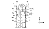
ここで、図6及び図7を参照して、転動体90について説明する。図6に示すように、転動体90は、一対のローラ91と、転動軸部92とを備える。一対のローラ91は、カバー本体71又は上延在部73aを挟んだ両側に配置される。転動軸部92は、カバー本体71又は上延在部73aに貫設され、一対のローラ91をカバー本体71又は延在部73に対して回転可能に支持する。
図7に示すように、隣接する二台の対基板作業モジュール3の各々には、筐体10の互いに対向する側面であって開口部11が形成される部位の上方部分に、被転動部材12が固定される。被転動部材12は、前後方向に延びる長尺の部材であり、筐体10に対してローラ91を前後方向へ転動可能に支持する。被転動部材12は、下固定部12aと、転動支持部12bとを備える。下固定部12aは、筐体10に固定される部位である。転動支持部12bは、筐体10に対して下固定部12aの上端からX方向外方へ延びる部位であり、ローラ91は、転動支持部12bの上面を転動する。
また、筐体10の側面には、被転動部材12が固定される部位の上方部分に、ローラ91を案内するガイド部材13が固定される。ガイド部材13は、ローラ91が被転動部材12から脱輪することを防止する。ガイド部材13は、上固定部13aと、延設部13bと、規制部13cとを備える。上固定部13aは、筐体10の側面に固定される部位である。延設部13bは、筐体10に対して固定部13aの下端からX方向外方に延設される部位であり、転動支持部12bを転動するローラ90の上方に配置される。規制部13cは、延設部13bの延設方向先端部分から下方へ延びる部位であり、被転動部材12を転動するローラ91の転動可能範囲を規制する。
また、二台の対基板作業モジュール3の各々には、互いに対向する筐体10の側面であって、各々の開口部11が形成される部位の下方部分に、筐体10の側面から突出する突出部14が設けられる。突出部14は、前後方向に延在し、カバー本体71の下端部分及び下延在部73bは、対向する突出部14の間に配置される。従って、対基板作業システム1は、左右方向に揺れるスライドカバー70の下端部分を突出部14に接触させることにより、スライドカバー70の左右方向への揺れを軽減することができる。また、突出部14には、スライドカバー70に接触する表面部分にエンボス加工が施されている。
このように、スライドカバー70は、筐体10に対してスライドすることにより、開口部11を開閉可能に設けられる。さらに、対基板作業システム1は、二台の対基板作業モジュール3の間に1枚のスライドカバー70を配置する。そして、1枚のスライドカバー70は、複数の転動体90を介して二台の対基板作業モジュール3の双方に対してスライド可能に支持される。即ち、対基板作業システム1は、1枚のスライドカバー70が二台の対基板作業モジュール3の対向する開口部11を開閉する構成となっている。これにより、対基板作業システム1は、二台の対基板作業モジュール3の間に必要とされる隙間を小さくすることができるので、対基板作業システム1に必要とされる設置スペースを小さくすることができる。
なお、スライドカバー70は、対基板作業モジュール3に対してスライド可能に支持されていればよく、対基板作業モジュール3に対するスライドカバー70の支持態様は、本実施形態のような、複数の転動体90を介して対基板作業モジュール3にスライド可能に支持される態様に限定されるものではない。
ここで、基板Kに対する部品の装着作業を行う際における対基板作業モジュール3の配置位置、即ち、ベース2に対して前方に引き出されていない状態における対基板作業モジュール3の配置位置を「基準位置」と定義する。
対基板作業モジュール3が基準位置に配置された状態において、スライドカバー70に設けられた全ての転動体90は、対基板作業モジュール3の被転動部材12に対して転動可能に支持される。スライドカバー70がカバー固定部80に連結された状態において、カバー本体71は、基準位置に配置された対基板作業モジュール3の開口部11と対応する位置に配置され、開口部11は、カバー本体71によって閉塞された状態となる。
一方、対基板作業モジュール3に対してスライドカバー70を前方へスライドさせることにより、切欠部74は、開口部11に対応する位置へ移動する。これにより、カバー本体71に塞がれていた開口部11の一部が露出するので、作業者は、露出した開口部11から筐体10の内部へアクセスすることができる。
次に、開口部11から対基板作業モジュール3の筐体10の内部にアクセスする手順を説明する。対基板作業システム1は、隣接する二台の対基板作業モジュール3の間に形成される隙間を小さくし、設置スペースの省スペース化を図っている。従って、作業者は、隣接する対基板作業モジュール3が前後方向において同じ位置に配置された状態で、開口部11から筐体10の内部にアクセスすることができない。そのため、筐体10の内部へアクセスする際、作業者は、隣接する二台の対基板作業モジュール3のうち一方の対基板作業モジュール3を前方へ引き出す。これにより、作業者は、隣接する二台の対基板作業モジュール3の前後位置をずらすことができる。
なお、説明の便宜上、以下において、隣接する二台の対基板作業モジュール3のうち前方に引き出す一方の対基板作業モジュール3を「第一対基板作業モジュール3A」と称し、後方に位置する他方の対基板作業モジュール3を「第二対基板作業モジュール3B」と称す。
このとき、図3及び図4に示すように、スライドカバー70がカバー固定部80に連結されていれば、スライドカバー70は、ベース2に対するスライドが規制される。このとき、第一対基板作業モジュール3Aを前方へ引き出すと、スライドカバー70は、第一対基板作業モジュール3Aに対してスライドする。その結果、第一対基板作業モジュール3Aは、第二対基板作業モジュール3Bの前端部分よりも前方へ移動した開口部11の一部が露出する一方、第二対基板作業モジュール3Bは、カバー固定部80に固定されたスライドカバー70によって開口部11が覆われた状態を維持できる。
従って、作業者は、第一対基板作業モジュール3Aの筐体10の内部前方へアクセスしようとする場合に、第一対基板作業モジュール3Aを前方へ引き出すことにより、露出した第一対基板作業モジュール3Aの開口部11から筐体10の内部前方へ容易にアクセスすることができる。その一方、第二対基板作業モジュール3Bは、スライドカバー70により開口部11が塞がれているので、作業者の手や所持品等が誤って第二対基板作業モジュール3Bの筐体10の内部に進入することを防止できる。よって、対基板作業システム1は、安全性の向上を図ることができる。
またこのとき、スライドカバー70は、全ての転動体90が第二対基板作業モジュール3Bの被転動部材12及びガイド部材13に支持されている。よって、対基板作業システム1は、第一対基板作業モジュール3Aが前方へ引き出された状態であっても、スライドカバー70を安定的に支持することができる。
さらに、図8に示すように、作業者は、カバー固定部80に対するスライドカバー70の連結を解除することにより、スライドカバー70を第二対基板作業モジュール3Bに対して前方へスライドさせることができる。そして、作業者は、第一対基板作業モジュール3Aを前方に引き出した状態から、スライドカバー70を第二対基板作業モジュール3Bに対して前方へスライドさせることにより、第二対基板作業モジュール3Bの開口部11に対応する位置に切欠部74を移動させることができる。
このように、作業者は、第二対基板作業モジュール3Bの筐体10の内部後方へアクセスしようとする場合に、第一対基板作業モジュール3Aを前方へ引き出した状態でスライドカバー70を前方へスライドさせることにより、露出した第二対基板作業モジュール3Bの開口部11から筐体10の内部後方へ容易にアクセスすることができる。
またこの場合、スライドカバー70の複数の転動体90のうち第二対基板作業モジュール3Bの被転動部材12及びガイド部材13よりも前方へ移動した転動体90は、第一対基板作業モジュール3Aの被転動部材12及びガイド部材13により転動可能に支持される。従って、対基板作業システム1は、第一対基板作業モジュール3Aを前方へ引き出した状態でスライドカバー70を前方へスライドさせた状態であっても、スライドカバー70を安定的に支持することができる。
スライドカバー70には、カバー本体71から後方へ延びる延在部73が形成され、複数の転動体90は、カバー本体71の上端部分及び上延在部73aの上端部分に対し、前後方向に間隔を空けつつ設けられている。この場合、二台の対基板作業モジュール3の前後位置を大きくずらした状態でスライドカバー70を前方へスライドさせたとしても、スライドカバー70が第一対基板作業モジュール3Aに支持された状態を維持しやすくすることができる。その一方、スライドカバー70には、後方側から前方側へ向けて切欠き形成された切欠部74が形成されている。よって、第二対基板作業モジュール3Bの開口部11を露出させようとした場合に、スライドカバー70の前方へのスライド量を小さくすることができる。よって、対基板作業モジュール3は、第二対基板作業モジュール3Bの開口部11を露出させた状態であっても、二台の対基板作業モジュール3の双方にスライドカバー70が支持された状態を維持しやすくすることができる。
以上説明したように、対基板作業システム1は、対基板作業モジュール3の筐体10に形成された開口部11を開閉可能なスライドカバー70を備えている。よって、対基板作業システム1は、開口部11を閉塞することにより基板Kに対する生産を行う際の安全性を確保しつつ、開口部11を開放することにより内部へのアクセスを容易に行うことができる。
以上、上記実施形態に基づいて本明細書に開示する対基板作業システムについて説明したが、上記形態に何ら限定されるものではなく、本開示の趣旨を逸脱しない範囲内で種々の変形改良が可能であることは容易に推察できるものである。
例えば、上記実施形態では、二台の対基板作業モジュール3の間に1枚のスライドカバー70がスライド可能に支持される場合について説明したが、これに限られるものではない。即ち、各々の対基板作業モジュール3が単独で2枚のスライドカバー70を備え、筐体10の配列方向を向く各側面に対し、各スライドカバー70が開口部11を開閉可能に支持される構成であってもよい。
上記実施形態では、スライドカバー70が一対の延在部73及び切欠部74を備え、上延在部73aと下延在部73bとの間に切欠部74を形成する場合について説明したが、必ずしもこれに限られるものではない。例えば、延在部73は、上延在部73aのみ又は下延在部73bのみで構成されていてもよく、延在部73がカバー本体71の中央部分から後方へ延在すると共に延在部73の上方及び下方に切欠部74が形成される構成であってもよい。
また、スライドカバー70は、一対の延在部73及び切欠部74を備えていない矩形板状に形成されたものであってもよい。この場合、カバー本体71の後端部分がカバー固定部80に対して取り外し可能に連結され、カバー本体71は、カバー固定部80に固定された状態で、開口部11を閉塞可能な寸法に形成される。
また、上記実施形態では、カバー本体71の上端部分及び上延在部73aの上端部分に複数の転動体90を設ける場合について説明したが、カバー本体71の下端部分及び下延在部73bの下端部分に複数の転動体90を設けてもよい。また、本実施形態では、対基板作業システム1は、被転動部材12の上方に設けたガイド部材13により、ローラ91が被転動部材12から脱輪することを防止する場合について説明したが、これに限られるものではない。例えば、対基板作業システム1は、被転動部材12の転動支持部12bに対し、上方へ延びる規制部12cを設けてもよい。この場合、対基板作業システム1は、ガイド部材13を省略できるので、筐体10の軽量化を図ることができる。
1:対基板作業システム、 2:ベース、 3:対基板作業モジュール、 11:開口部、 70:スライドカバー、 71:カバー本体、 73:延在部、 74:切欠部、 80:カバー固定部、 K:基板
Claims (5)
- 1又は複数のベースと、
前記ベースの上面に配列されると共に、前記ベースに対し配列方向に直交する方向へ引き出し可能に設けられ、且つ、前記配列方向に基板を搬入出するための開口部をそれぞれ備えた複数の対基板作業モジュールと、
隣接する二台の前記対基板作業モジュールの間に、前記隣接する二台の前記対基板作業モジュールの各々に対してスライド可能に設けられ、且つ、スライドすることにより前記開口部を開閉可能なスライドカバーと、
を備える対基板作業システム。 - 前記スライドカバーは、前記隣接する二台の前記対基板作業モジュールの側面の間に1つ設けられると共に、前記隣接する二台の前記対基板作業モジュールの双方に対してスライド可能に支持される、請求項1に記載の対基板作業システム。
- 前記対基板作業モジュールは、前記ベースに固定され、前記スライドカバーの後方側を連結可能なカバー固定部を備える、請求項2に記載の対基板作業システム。
- 前記スライドカバーは、
前記スライドカバーによる前記開口部の閉塞時において前記開口部と対応する位置に配置されるカバー本体と、
前記カバー本体から後方へ延びる部位であって、前記スライドカバーによる前記開口部の閉塞時において前記開口部よりも後方に配置されると共に、前記カバー固定部に連結可能な延在部と、
前記延在部の上方又は下方に切欠き形成された部位であって、前記スライドカバーをスライドさせることにより前記開口部と対応する位置に配置可能な切欠部と、
を備える、請求項3に記載の対基板作業システム。 - 前記延在部は、前記カバー本体の上端部分又は下端部分から後方へ延び、
前記スライドカバーは、前記カバー本体及び前記カバー本体の上端部分から延びる前記延在部の上端部分、又は、前記カバー本体及び前記カバー本体の下端部分から延びる前記延在部の下端部分を、前記隣接する二台の前記対基板作業モジュールの各々に対してスライド可能に支持される、請求項4に記載の対基板作業システム。
Priority Applications (2)
| Application Number | Priority Date | Filing Date | Title |
|---|---|---|---|
| JP2019530321A JP6817442B2 (ja) | 2017-07-21 | 2017-07-21 | 対基板作業システム |
| PCT/JP2017/026416 WO2019016933A1 (ja) | 2017-07-21 | 2017-07-21 | 対基板作業システム |
Applications Claiming Priority (1)
| Application Number | Priority Date | Filing Date | Title |
|---|---|---|---|
| PCT/JP2017/026416 WO2019016933A1 (ja) | 2017-07-21 | 2017-07-21 | 対基板作業システム |
Publications (1)
| Publication Number | Publication Date |
|---|---|
| WO2019016933A1 true WO2019016933A1 (ja) | 2019-01-24 |
Family
ID=65015915
Family Applications (1)
| Application Number | Title | Priority Date | Filing Date |
|---|---|---|---|
| PCT/JP2017/026416 Ceased WO2019016933A1 (ja) | 2017-07-21 | 2017-07-21 | 対基板作業システム |
Country Status (2)
| Country | Link |
|---|---|
| JP (1) | JP6817442B2 (ja) |
| WO (1) | WO2019016933A1 (ja) |
Cited By (1)
| Publication number | Priority date | Publication date | Assignee | Title |
|---|---|---|---|---|
| WO2024079911A1 (ja) * | 2022-10-14 | 2024-04-18 | 株式会社Fuji | 部品実装機 |
Citations (2)
| Publication number | Priority date | Publication date | Assignee | Title |
|---|---|---|---|---|
| JP2014099555A (ja) * | 2012-11-15 | 2014-05-29 | Yamaha Motor Co Ltd | 基板作業システム、基板搬送装置および基板作業装置 |
| JP2015065484A (ja) * | 2002-07-19 | 2015-04-09 | 富士機械製造株式会社 | 対基板作業システム |
-
2017
- 2017-07-21 WO PCT/JP2017/026416 patent/WO2019016933A1/ja not_active Ceased
- 2017-07-21 JP JP2019530321A patent/JP6817442B2/ja active Active
Patent Citations (2)
| Publication number | Priority date | Publication date | Assignee | Title |
|---|---|---|---|---|
| JP2015065484A (ja) * | 2002-07-19 | 2015-04-09 | 富士機械製造株式会社 | 対基板作業システム |
| JP2014099555A (ja) * | 2012-11-15 | 2014-05-29 | Yamaha Motor Co Ltd | 基板作業システム、基板搬送装置および基板作業装置 |
Cited By (1)
| Publication number | Priority date | Publication date | Assignee | Title |
|---|---|---|---|---|
| WO2024079911A1 (ja) * | 2022-10-14 | 2024-04-18 | 株式会社Fuji | 部品実装機 |
Also Published As
| Publication number | Publication date |
|---|---|
| JP6817442B2 (ja) | 2021-01-20 |
| JPWO2019016933A1 (ja) | 2020-03-19 |
Similar Documents
| Publication | Publication Date | Title |
|---|---|---|
| US20220234157A1 (en) | Gantry type conveying device and processing line | |
| CN103703876B (zh) | 元件供给装置 | |
| CN110583106B (zh) | 元件供给台车及元件安装装置 | |
| JP5975508B2 (ja) | 実装ヘッドユニット、部品実装装置及び基板の製造方法 | |
| WO2011077880A1 (ja) | 電子回路部品供給装置 | |
| CN107950085A (zh) | 另置式带盘保持装置 | |
| JP2001021457A (ja) | 試料交換機を有する分析システム | |
| JP6074436B2 (ja) | 部品供給装置 | |
| JP6817442B2 (ja) | 対基板作業システム | |
| US5575058A (en) | Connector housing supplying device | |
| JP2009278935A (ja) | 食品処理システム | |
| JP6040255B2 (ja) | 部品供給装置 | |
| JP2016013600A (ja) | 工作機械 | |
| JP2012028413A (ja) | 連続拡散処理装置 | |
| JP2022077857A (ja) | テープフィーダおよび部品搭載装置 | |
| JP5771487B2 (ja) | 電線供給装置 | |
| KR20170016616A (ko) | 저압화학기상증착 장치 | |
| JP2009032964A (ja) | 供給装置、及び表面実装機 | |
| JP5885856B2 (ja) | 部品供給装置 | |
| JP7396890B2 (ja) | 部品供給装置及び部品実装装置 | |
| KR100534747B1 (ko) | 차량 도어 행거장치 | |
| JP2022077858A (ja) | テープフィーダおよび部品搭載装置 | |
| JP4661711B2 (ja) | 電子部品供給装置 | |
| KR20150139293A (ko) | 기판처리장치 및 이를 포함하는 기판처리 시스템 | |
| JP2008288454A (ja) | 表面実装装置 |
Legal Events
| Date | Code | Title | Description |
|---|---|---|---|
| 121 | Ep: the epo has been informed by wipo that ep was designated in this application |
Ref document number: 17918241 Country of ref document: EP Kind code of ref document: A1 |
|
| ENP | Entry into the national phase |
Ref document number: 2019530321 Country of ref document: JP Kind code of ref document: A |
|
| NENP | Non-entry into the national phase |
Ref country code: DE |
|
| 122 | Ep: pct application non-entry in european phase |
Ref document number: 17918241 Country of ref document: EP Kind code of ref document: A1 |