WO2019013334A1 - Powder for ceramic shaping, ceramic shaped article, and method for manufacturing same - Google Patents
Powder for ceramic shaping, ceramic shaped article, and method for manufacturing same Download PDFInfo
- Publication number
- WO2019013334A1 WO2019013334A1 PCT/JP2018/026539 JP2018026539W WO2019013334A1 WO 2019013334 A1 WO2019013334 A1 WO 2019013334A1 JP 2018026539 W JP2018026539 W JP 2018026539W WO 2019013334 A1 WO2019013334 A1 WO 2019013334A1
- Authority
- WO
- WIPO (PCT)
- Prior art keywords
- powder
- ceramic
- absorber
- composition
- particles
- Prior art date
Links
Images


Classifications
-
- B—PERFORMING OPERATIONS; TRANSPORTING
- B28—WORKING CEMENT, CLAY, OR STONE
- B28B—SHAPING CLAY OR OTHER CERAMIC COMPOSITIONS; SHAPING SLAG; SHAPING MIXTURES CONTAINING CEMENTITIOUS MATERIAL, e.g. PLASTER
- B28B1/00—Producing shaped prefabricated articles from the material
- B28B1/30—Producing shaped prefabricated articles from the material by applying the material on to a core or other moulding surface to form a layer thereon
-
- B—PERFORMING OPERATIONS; TRANSPORTING
- B28—WORKING CEMENT, CLAY, OR STONE
- B28B—SHAPING CLAY OR OTHER CERAMIC COMPOSITIONS; SHAPING SLAG; SHAPING MIXTURES CONTAINING CEMENTITIOUS MATERIAL, e.g. PLASTER
- B28B1/00—Producing shaped prefabricated articles from the material
- B28B1/001—Rapid manufacturing of 3D objects by additive depositing, agglomerating or laminating of material
-
- B—PERFORMING OPERATIONS; TRANSPORTING
- B29—WORKING OF PLASTICS; WORKING OF SUBSTANCES IN A PLASTIC STATE IN GENERAL
- B29C—SHAPING OR JOINING OF PLASTICS; SHAPING OF MATERIAL IN A PLASTIC STATE, NOT OTHERWISE PROVIDED FOR; AFTER-TREATMENT OF THE SHAPED PRODUCTS, e.g. REPAIRING
- B29C64/00—Additive manufacturing, i.e. manufacturing of three-dimensional [3D] objects by additive deposition, additive agglomeration or additive layering, e.g. by 3D printing, stereolithography or selective laser sintering
- B29C64/10—Processes of additive manufacturing
- B29C64/141—Processes of additive manufacturing using only solid materials
- B29C64/153—Processes of additive manufacturing using only solid materials using layers of powder being selectively joined, e.g. by selective laser sintering or melting
-
- B—PERFORMING OPERATIONS; TRANSPORTING
- B32—LAYERED PRODUCTS
- B32B—LAYERED PRODUCTS, i.e. PRODUCTS BUILT-UP OF STRATA OF FLAT OR NON-FLAT, e.g. CELLULAR OR HONEYCOMB, FORM
- B32B18/00—Layered products essentially comprising ceramics, e.g. refractory products
-
- B—PERFORMING OPERATIONS; TRANSPORTING
- B33—ADDITIVE MANUFACTURING TECHNOLOGY
- B33Y—ADDITIVE MANUFACTURING, i.e. MANUFACTURING OF THREE-DIMENSIONAL [3-D] OBJECTS BY ADDITIVE DEPOSITION, ADDITIVE AGGLOMERATION OR ADDITIVE LAYERING, e.g. BY 3-D PRINTING, STEREOLITHOGRAPHY OR SELECTIVE LASER SINTERING
- B33Y10/00—Processes of additive manufacturing
-
- B—PERFORMING OPERATIONS; TRANSPORTING
- B33—ADDITIVE MANUFACTURING TECHNOLOGY
- B33Y—ADDITIVE MANUFACTURING, i.e. MANUFACTURING OF THREE-DIMENSIONAL [3-D] OBJECTS BY ADDITIVE DEPOSITION, ADDITIVE AGGLOMERATION OR ADDITIVE LAYERING, e.g. BY 3-D PRINTING, STEREOLITHOGRAPHY OR SELECTIVE LASER SINTERING
- B33Y70/00—Materials specially adapted for additive manufacturing
- B33Y70/10—Composites of different types of material, e.g. mixtures of ceramics and polymers or mixtures of metals and biomaterials
-
- C—CHEMISTRY; METALLURGY
- C04—CEMENTS; CONCRETE; ARTIFICIAL STONE; CERAMICS; REFRACTORIES
- C04B—LIME, MAGNESIA; SLAG; CEMENTS; COMPOSITIONS THEREOF, e.g. MORTARS, CONCRETE OR LIKE BUILDING MATERIALS; ARTIFICIAL STONE; CERAMICS; REFRACTORIES; TREATMENT OF NATURAL STONE
- C04B35/00—Shaped ceramic products characterised by their composition; Ceramics compositions; Processing powders of inorganic compounds preparatory to the manufacturing of ceramic products
- C04B35/01—Shaped ceramic products characterised by their composition; Ceramics compositions; Processing powders of inorganic compounds preparatory to the manufacturing of ceramic products based on oxide ceramics
- C04B35/10—Shaped ceramic products characterised by their composition; Ceramics compositions; Processing powders of inorganic compounds preparatory to the manufacturing of ceramic products based on oxide ceramics based on aluminium oxide
- C04B35/101—Refractories from grain sized mixtures
- C04B35/106—Refractories from grain sized mixtures containing zirconium oxide or zircon (ZrSiO4)
-
- C—CHEMISTRY; METALLURGY
- C04—CEMENTS; CONCRETE; ARTIFICIAL STONE; CERAMICS; REFRACTORIES
- C04B—LIME, MAGNESIA; SLAG; CEMENTS; COMPOSITIONS THEREOF, e.g. MORTARS, CONCRETE OR LIKE BUILDING MATERIALS; ARTIFICIAL STONE; CERAMICS; REFRACTORIES; TREATMENT OF NATURAL STONE
- C04B35/00—Shaped ceramic products characterised by their composition; Ceramics compositions; Processing powders of inorganic compounds preparatory to the manufacturing of ceramic products
- C04B35/01—Shaped ceramic products characterised by their composition; Ceramics compositions; Processing powders of inorganic compounds preparatory to the manufacturing of ceramic products based on oxide ceramics
- C04B35/10—Shaped ceramic products characterised by their composition; Ceramics compositions; Processing powders of inorganic compounds preparatory to the manufacturing of ceramic products based on oxide ceramics based on aluminium oxide
- C04B35/111—Fine ceramics
- C04B35/117—Composites
- C04B35/119—Composites with zirconium oxide
-
- C—CHEMISTRY; METALLURGY
- C04—CEMENTS; CONCRETE; ARTIFICIAL STONE; CERAMICS; REFRACTORIES
- C04B—LIME, MAGNESIA; SLAG; CEMENTS; COMPOSITIONS THEREOF, e.g. MORTARS, CONCRETE OR LIKE BUILDING MATERIALS; ARTIFICIAL STONE; CERAMICS; REFRACTORIES; TREATMENT OF NATURAL STONE
- C04B35/00—Shaped ceramic products characterised by their composition; Ceramics compositions; Processing powders of inorganic compounds preparatory to the manufacturing of ceramic products
- C04B35/01—Shaped ceramic products characterised by their composition; Ceramics compositions; Processing powders of inorganic compounds preparatory to the manufacturing of ceramic products based on oxide ceramics
- C04B35/14—Shaped ceramic products characterised by their composition; Ceramics compositions; Processing powders of inorganic compounds preparatory to the manufacturing of ceramic products based on oxide ceramics based on silica
-
- C—CHEMISTRY; METALLURGY
- C04—CEMENTS; CONCRETE; ARTIFICIAL STONE; CERAMICS; REFRACTORIES
- C04B—LIME, MAGNESIA; SLAG; CEMENTS; COMPOSITIONS THEREOF, e.g. MORTARS, CONCRETE OR LIKE BUILDING MATERIALS; ARTIFICIAL STONE; CERAMICS; REFRACTORIES; TREATMENT OF NATURAL STONE
- C04B35/00—Shaped ceramic products characterised by their composition; Ceramics compositions; Processing powders of inorganic compounds preparatory to the manufacturing of ceramic products
- C04B35/01—Shaped ceramic products characterised by their composition; Ceramics compositions; Processing powders of inorganic compounds preparatory to the manufacturing of ceramic products based on oxide ceramics
- C04B35/16—Shaped ceramic products characterised by their composition; Ceramics compositions; Processing powders of inorganic compounds preparatory to the manufacturing of ceramic products based on oxide ceramics based on silicates other than clay
- C04B35/18—Shaped ceramic products characterised by their composition; Ceramics compositions; Processing powders of inorganic compounds preparatory to the manufacturing of ceramic products based on oxide ceramics based on silicates other than clay rich in aluminium oxide
- C04B35/195—Alkaline earth aluminosilicates, e.g. cordierite or anorthite
-
- C—CHEMISTRY; METALLURGY
- C04—CEMENTS; CONCRETE; ARTIFICIAL STONE; CERAMICS; REFRACTORIES
- C04B—LIME, MAGNESIA; SLAG; CEMENTS; COMPOSITIONS THEREOF, e.g. MORTARS, CONCRETE OR LIKE BUILDING MATERIALS; ARTIFICIAL STONE; CERAMICS; REFRACTORIES; TREATMENT OF NATURAL STONE
- C04B35/00—Shaped ceramic products characterised by their composition; Ceramics compositions; Processing powders of inorganic compounds preparatory to the manufacturing of ceramic products
- C04B35/01—Shaped ceramic products characterised by their composition; Ceramics compositions; Processing powders of inorganic compounds preparatory to the manufacturing of ceramic products based on oxide ceramics
- C04B35/44—Shaped ceramic products characterised by their composition; Ceramics compositions; Processing powders of inorganic compounds preparatory to the manufacturing of ceramic products based on oxide ceramics based on aluminates
-
- C—CHEMISTRY; METALLURGY
- C04—CEMENTS; CONCRETE; ARTIFICIAL STONE; CERAMICS; REFRACTORIES
- C04B—LIME, MAGNESIA; SLAG; CEMENTS; COMPOSITIONS THEREOF, e.g. MORTARS, CONCRETE OR LIKE BUILDING MATERIALS; ARTIFICIAL STONE; CERAMICS; REFRACTORIES; TREATMENT OF NATURAL STONE
- C04B35/00—Shaped ceramic products characterised by their composition; Ceramics compositions; Processing powders of inorganic compounds preparatory to the manufacturing of ceramic products
- C04B35/01—Shaped ceramic products characterised by their composition; Ceramics compositions; Processing powders of inorganic compounds preparatory to the manufacturing of ceramic products based on oxide ceramics
- C04B35/48—Shaped ceramic products characterised by their composition; Ceramics compositions; Processing powders of inorganic compounds preparatory to the manufacturing of ceramic products based on oxide ceramics based on zirconium or hafnium oxides, zirconates, zircon or hafnates
- C04B35/486—Fine ceramics
- C04B35/488—Composites
-
- C—CHEMISTRY; METALLURGY
- C04—CEMENTS; CONCRETE; ARTIFICIAL STONE; CERAMICS; REFRACTORIES
- C04B—LIME, MAGNESIA; SLAG; CEMENTS; COMPOSITIONS THEREOF, e.g. MORTARS, CONCRETE OR LIKE BUILDING MATERIALS; ARTIFICIAL STONE; CERAMICS; REFRACTORIES; TREATMENT OF NATURAL STONE
- C04B35/00—Shaped ceramic products characterised by their composition; Ceramics compositions; Processing powders of inorganic compounds preparatory to the manufacturing of ceramic products
- C04B35/50—Shaped ceramic products characterised by their composition; Ceramics compositions; Processing powders of inorganic compounds preparatory to the manufacturing of ceramic products based on rare-earth compounds
-
- C—CHEMISTRY; METALLURGY
- C04—CEMENTS; CONCRETE; ARTIFICIAL STONE; CERAMICS; REFRACTORIES
- C04B—LIME, MAGNESIA; SLAG; CEMENTS; COMPOSITIONS THEREOF, e.g. MORTARS, CONCRETE OR LIKE BUILDING MATERIALS; ARTIFICIAL STONE; CERAMICS; REFRACTORIES; TREATMENT OF NATURAL STONE
- C04B35/00—Shaped ceramic products characterised by their composition; Ceramics compositions; Processing powders of inorganic compounds preparatory to the manufacturing of ceramic products
- C04B35/622—Forming processes; Processing powders of inorganic compounds preparatory to the manufacturing of ceramic products
- C04B35/64—Burning or sintering processes
-
- C—CHEMISTRY; METALLURGY
- C04—CEMENTS; CONCRETE; ARTIFICIAL STONE; CERAMICS; REFRACTORIES
- C04B—LIME, MAGNESIA; SLAG; CEMENTS; COMPOSITIONS THEREOF, e.g. MORTARS, CONCRETE OR LIKE BUILDING MATERIALS; ARTIFICIAL STONE; CERAMICS; REFRACTORIES; TREATMENT OF NATURAL STONE
- C04B35/00—Shaped ceramic products characterised by their composition; Ceramics compositions; Processing powders of inorganic compounds preparatory to the manufacturing of ceramic products
- C04B35/622—Forming processes; Processing powders of inorganic compounds preparatory to the manufacturing of ceramic products
- C04B35/653—Processes involving a melting step
-
- C—CHEMISTRY; METALLURGY
- C04—CEMENTS; CONCRETE; ARTIFICIAL STONE; CERAMICS; REFRACTORIES
- C04B—LIME, MAGNESIA; SLAG; CEMENTS; COMPOSITIONS THEREOF, e.g. MORTARS, CONCRETE OR LIKE BUILDING MATERIALS; ARTIFICIAL STONE; CERAMICS; REFRACTORIES; TREATMENT OF NATURAL STONE
- C04B2235/00—Aspects relating to ceramic starting mixtures or sintered ceramic products
- C04B2235/02—Composition of constituents of the starting material or of secondary phases of the final product
- C04B2235/30—Constituents and secondary phases not being of a fibrous nature
- C04B2235/32—Metal oxides, mixed metal oxides, or oxide-forming salts thereof, e.g. carbonates, nitrates, (oxy)hydroxides, chlorides
- C04B2235/3224—Rare earth oxide or oxide forming salts thereof, e.g. scandium oxide
- C04B2235/3225—Yttrium oxide or oxide-forming salts thereof
-
- C—CHEMISTRY; METALLURGY
- C04—CEMENTS; CONCRETE; ARTIFICIAL STONE; CERAMICS; REFRACTORIES
- C04B—LIME, MAGNESIA; SLAG; CEMENTS; COMPOSITIONS THEREOF, e.g. MORTARS, CONCRETE OR LIKE BUILDING MATERIALS; ARTIFICIAL STONE; CERAMICS; REFRACTORIES; TREATMENT OF NATURAL STONE
- C04B2235/00—Aspects relating to ceramic starting mixtures or sintered ceramic products
- C04B2235/02—Composition of constituents of the starting material or of secondary phases of the final product
- C04B2235/30—Constituents and secondary phases not being of a fibrous nature
- C04B2235/34—Non-metal oxides, non-metal mixed oxides, or salts thereof that form the non-metal oxides upon heating, e.g. carbonates, nitrates, (oxy)hydroxides, chlorides
- C04B2235/3418—Silicon oxide, silicic acids, or oxide forming salts thereof, e.g. silica sol, fused silica, silica fume, cristobalite, quartz or flint
-
- C—CHEMISTRY; METALLURGY
- C04—CEMENTS; CONCRETE; ARTIFICIAL STONE; CERAMICS; REFRACTORIES
- C04B—LIME, MAGNESIA; SLAG; CEMENTS; COMPOSITIONS THEREOF, e.g. MORTARS, CONCRETE OR LIKE BUILDING MATERIALS; ARTIFICIAL STONE; CERAMICS; REFRACTORIES; TREATMENT OF NATURAL STONE
- C04B2235/00—Aspects relating to ceramic starting mixtures or sintered ceramic products
- C04B2235/02—Composition of constituents of the starting material or of secondary phases of the final product
- C04B2235/50—Constituents or additives of the starting mixture chosen for their shape or used because of their shape or their physical appearance
- C04B2235/54—Particle size related information
- C04B2235/5418—Particle size related information expressed by the size of the particles or aggregates thereof
- C04B2235/5436—Particle size related information expressed by the size of the particles or aggregates thereof micrometer sized, i.e. from 1 to 100 micron
-
- C—CHEMISTRY; METALLURGY
- C04—CEMENTS; CONCRETE; ARTIFICIAL STONE; CERAMICS; REFRACTORIES
- C04B—LIME, MAGNESIA; SLAG; CEMENTS; COMPOSITIONS THEREOF, e.g. MORTARS, CONCRETE OR LIKE BUILDING MATERIALS; ARTIFICIAL STONE; CERAMICS; REFRACTORIES; TREATMENT OF NATURAL STONE
- C04B2235/00—Aspects relating to ceramic starting mixtures or sintered ceramic products
- C04B2235/02—Composition of constituents of the starting material or of secondary phases of the final product
- C04B2235/50—Constituents or additives of the starting mixture chosen for their shape or used because of their shape or their physical appearance
- C04B2235/54—Particle size related information
- C04B2235/5418—Particle size related information expressed by the size of the particles or aggregates thereof
- C04B2235/5445—Particle size related information expressed by the size of the particles or aggregates thereof submicron sized, i.e. from 0,1 to 1 micron
-
- C—CHEMISTRY; METALLURGY
- C04—CEMENTS; CONCRETE; ARTIFICIAL STONE; CERAMICS; REFRACTORIES
- C04B—LIME, MAGNESIA; SLAG; CEMENTS; COMPOSITIONS THEREOF, e.g. MORTARS, CONCRETE OR LIKE BUILDING MATERIALS; ARTIFICIAL STONE; CERAMICS; REFRACTORIES; TREATMENT OF NATURAL STONE
- C04B2235/00—Aspects relating to ceramic starting mixtures or sintered ceramic products
- C04B2235/60—Aspects relating to the preparation, properties or mechanical treatment of green bodies or pre-forms
- C04B2235/602—Making the green bodies or pre-forms by moulding
- C04B2235/6026—Computer aided shaping, e.g. rapid prototyping
-
- C—CHEMISTRY; METALLURGY
- C04—CEMENTS; CONCRETE; ARTIFICIAL STONE; CERAMICS; REFRACTORIES
- C04B—LIME, MAGNESIA; SLAG; CEMENTS; COMPOSITIONS THEREOF, e.g. MORTARS, CONCRETE OR LIKE BUILDING MATERIALS; ARTIFICIAL STONE; CERAMICS; REFRACTORIES; TREATMENT OF NATURAL STONE
- C04B2235/00—Aspects relating to ceramic starting mixtures or sintered ceramic products
- C04B2235/65—Aspects relating to heat treatments of ceramic bodies such as green ceramics or pre-sintered ceramics, e.g. burning, sintering or melting processes
- C04B2235/66—Specific sintering techniques, e.g. centrifugal sintering
- C04B2235/665—Local sintering, e.g. laser sintering
-
- C—CHEMISTRY; METALLURGY
- C04—CEMENTS; CONCRETE; ARTIFICIAL STONE; CERAMICS; REFRACTORIES
- C04B—LIME, MAGNESIA; SLAG; CEMENTS; COMPOSITIONS THEREOF, e.g. MORTARS, CONCRETE OR LIKE BUILDING MATERIALS; ARTIFICIAL STONE; CERAMICS; REFRACTORIES; TREATMENT OF NATURAL STONE
- C04B2235/00—Aspects relating to ceramic starting mixtures or sintered ceramic products
- C04B2235/65—Aspects relating to heat treatments of ceramic bodies such as green ceramics or pre-sintered ceramics, e.g. burning, sintering or melting processes
- C04B2235/66—Specific sintering techniques, e.g. centrifugal sintering
- C04B2235/667—Sintering using wave energy, e.g. microwave sintering
-
- C—CHEMISTRY; METALLURGY
- C04—CEMENTS; CONCRETE; ARTIFICIAL STONE; CERAMICS; REFRACTORIES
- C04B—LIME, MAGNESIA; SLAG; CEMENTS; COMPOSITIONS THEREOF, e.g. MORTARS, CONCRETE OR LIKE BUILDING MATERIALS; ARTIFICIAL STONE; CERAMICS; REFRACTORIES; TREATMENT OF NATURAL STONE
- C04B2235/00—Aspects relating to ceramic starting mixtures or sintered ceramic products
- C04B2235/70—Aspects relating to sintered or melt-casted ceramic products
- C04B2235/74—Physical characteristics
- C04B2235/76—Crystal structural characteristics, e.g. symmetry
- C04B2235/762—Cubic symmetry, e.g. beta-SiC
- C04B2235/764—Garnet structure A3B2(CO4)3
-
- C—CHEMISTRY; METALLURGY
- C04—CEMENTS; CONCRETE; ARTIFICIAL STONE; CERAMICS; REFRACTORIES
- C04B—LIME, MAGNESIA; SLAG; CEMENTS; COMPOSITIONS THEREOF, e.g. MORTARS, CONCRETE OR LIKE BUILDING MATERIALS; ARTIFICIAL STONE; CERAMICS; REFRACTORIES; TREATMENT OF NATURAL STONE
- C04B2235/00—Aspects relating to ceramic starting mixtures or sintered ceramic products
- C04B2235/70—Aspects relating to sintered or melt-casted ceramic products
- C04B2235/74—Physical characteristics
- C04B2235/77—Density
-
- C—CHEMISTRY; METALLURGY
- C04—CEMENTS; CONCRETE; ARTIFICIAL STONE; CERAMICS; REFRACTORIES
- C04B—LIME, MAGNESIA; SLAG; CEMENTS; COMPOSITIONS THEREOF, e.g. MORTARS, CONCRETE OR LIKE BUILDING MATERIALS; ARTIFICIAL STONE; CERAMICS; REFRACTORIES; TREATMENT OF NATURAL STONE
- C04B2235/00—Aspects relating to ceramic starting mixtures or sintered ceramic products
- C04B2235/70—Aspects relating to sintered or melt-casted ceramic products
- C04B2235/96—Properties of ceramic products, e.g. mechanical properties such as strength, toughness, wear resistance
-
- Y—GENERAL TAGGING OF NEW TECHNOLOGICAL DEVELOPMENTS; GENERAL TAGGING OF CROSS-SECTIONAL TECHNOLOGIES SPANNING OVER SEVERAL SECTIONS OF THE IPC; TECHNICAL SUBJECTS COVERED BY FORMER USPC CROSS-REFERENCE ART COLLECTIONS [XRACs] AND DIGESTS
- Y02—TECHNOLOGIES OR APPLICATIONS FOR MITIGATION OR ADAPTATION AGAINST CLIMATE CHANGE
- Y02P—CLIMATE CHANGE MITIGATION TECHNOLOGIES IN THE PRODUCTION OR PROCESSING OF GOODS
- Y02P10/00—Technologies related to metal processing
- Y02P10/25—Process efficiency
Definitions
- the present invention relates to a powder used when forming a ceramic shaped article by laser irradiation and a manufacturing method using the powder.
- Non-Patent Document 1 the melting point is lowered by using an Al 2 O 3 -ZrO 2 eutectic system, and when it is melted and solidified, a microstructure unique to the eutectic system is formed to be high.
- Methods have also been proposed to realize mechanical strength.
- it has succeeded in satisfying the point of improving the compactness of a shaped object, a large number of projections are generated on the surface of the shaped object, and the situation has not reached a sufficient modeling accuracy.
- the wavelength of the laser light is Nd: YAG (about 1 ⁇ m), and neither Al 2 O 3 nor ZrO 2 show clear absorption even if the melting point is lowered in the eutectic system, so the material system is melted and solidified. In order to do that, you need some energy. In such a system, there are problems such as nonuniform melting in a desired shaped portion and wide nonuniform sintering region around the desired shape, accompanied by light diffusion in powder.
- the powder for ceramic formation of the present invention is a powder for ceramic formation for obtaining a shaped article by repeatedly sintering or melting and solidifying the powder in a portion irradiated with a laser beam successively, Is an absorber comprising a plurality of compositions, at least one composition of said composition exhibiting an absorption relatively higher for said laser light than the other compositions, said absorption resulting from the irradiation of said laser light It is characterized in that at least a part of the body changes to another composition having relatively low absorption to the laser light.
- a ceramic shaped article in which a shaped article is obtained by repeating sintering or melting and solidifying powder sequentially in a portion irradiated with laser light to obtain a shaped article, (I) disposing the above-mentioned powder for ceramic formation in a laser irradiation part, (Ii) applying a laser to the powder for ceramic formation based on three-dimensional formation data to sinter or melt the powder for ceramic formation and then solidify; and (iii) the step (i) ) And (ii) to produce a shaped article, It is characterized by having.
- the powder for ceramic formation of the present invention When the powder for ceramic formation of the present invention is used, a region after sintering or melting is obtained by changing a part of the absorber to another composition having relatively low absorption with respect to the laser light by laser light irradiation. Is less susceptible to laser irradiation during subsequent shaping.
- the absorber can also reduce light diffusion because the absorption with respect to the laser light is relatively higher than that of the other composition constituting the powder. As a result, it is possible to realize production of a ceramic shaped article with high shaping accuracy.
- Powder is an aggregate of particles that can be recognized as isolated particles. Moreover, powder consists of several compositions.
- the composition is composed of a plurality of components (elements or compounds).
- powder is composed of a plurality of compositions, when many kinds of particles consisting of one kind of composition are mixed, or one kind or many kinds of particles consisting of plural kinds of composition are mixed I mean the case.
- the absorber is defined as a composition having a relatively high absorption capacity for the laser light used as compared to other compositions constituting the powder. In other words, the absorber has the highest ability to absorb laser light among the compositions contained in the powder.
- At least one composition constituting the powder of the present invention is an absorber capable of absorbing laser light.
- the absorptivity of the absorber is preferably an absorptivity of 10% or more for the laser light of the wavelength used.
- the absorption rate is more preferably 40% or more, and still more preferably 60% or more.
- a general spectrometer may be used, and an integrator alone is used to measure the assumed wavelength (near the laser wavelength used in manufacturing) to the absorber alone filled in the sample plate. Irradiate and measure.
- the absorptivity is calculated from the ratio using the case where there is no sample as reference data.
- the powder of the present invention is composed of a plurality of compositions of two or more types, and the plurality of compositions include at least one composition which is an absorber.
- Each particle constituting the powder may consist of a single composition, or one particle may consist of a plurality of compositions. The following will be described in order by case.
- the powder is composed of particles consisting of a single composition.
- a plurality of compositions are composed of three types of Al 2 O 3 , ZrO 2 , and Tb 4 O 7 (absorber), Al 2 O 3 particles, ZrO 2 particles, Tb 4 O 7 particles Are present, and the powder is constituted as a mixture of those particles.
- the powder contains particles composed of two or more kinds of compositions.
- the composition Al 2 O 3, ZrO 2 , Tb 4 O 7 when configured in three (absorbers), only particles made of Al 2 O 3 -ZrO 2 -Tb 4 O 7 and the condition being constituted, Al 2 O 3 -ZrO 2 particles, as saying that Tb 4 O 7 particles, a state such as Al 2 O 3 -ZrO 2 belong to the same particles.
- the Tb 4 O 7 which is an example of the absorber according to the present invention should be maintained in the Tb 4 O 7 state. Is preferred.
- the composition which is an absorber is preferable in the condition where it constitutes particles alone, regardless of how the other compositions are constituted.
- the flowability of the powder is important in the case where a powder bed layer is formed using a recoater by a powder bed fusion bonding method, and in the case where powder is sprayed from a nozzle in cladding method. It is.
- the powder it is preferable to use a powder that satisfies 40 [sec / 50 g] or less as a fluidity index.
- the particles are preferably spherical. However, spherical shape is not essential if the above liquidity index is satisfied.
- the particle size of the particles of the composition constituting the absorber (the particle size is not the single particle but the median value of the particles having the same composition, but not the single particle) It is preferable that it is 1/5 or less of the particle size of particle
- the powder of this invention does not contain the resin binder.
- a process of explosively burning away may be generated by laser irradiation, which may cause internal inclusion of pores and the like in the modeling region.
- carbon is contained, in addition to being combined with oxygen to form a gas, the volume occupied by the carbon component may be vacancies, so the amount is preferably small. Therefore, the content of carbon is preferably 1000 ppm or less in molar ratio with respect to the metal elements of the plurality of compositions constituting the powder.
- carbon is contained, it is oxidized by laser irradiation and oxidized to gasify and adversely affect the formation, so it is incorporated into a formed article with a change to a different composition by laser irradiation like the absorber of the present invention Is preferred.
- the absorber, the composition and the particles have been described, but the powder for ceramic formation in the present invention may be in a crystalline or amorphous state, or a mixture thereof.
- the composition it is not necessary for the composition to completely match between the powder and the shaped article, and in particular, there may be a difference such as an oxidation state or a nitriding state. Therefore, it is also preferable to control the atmosphere during the shaping process, and not only in the atmosphere, but also in an inactive state such as nitrogen or other rare gas atmosphere, a state where it is easily reduced due to partial hydrogen content or decompression, etc. Is also preferred. Such atmosphere control does not exclude the inclusion of a partially metallic composition as the raw material powder.
- the present invention is a powder for forming a ceramic, but the present invention is not limited to a state where the formed object is made of a ceramic consisting of 100% crystals, and a part of the object is obtained when desired physical property values are obtained. Alternatively, a region in an amorphous state, a region in a reduced metal state, or the like may be formed over half.
- the absorber suitable for the present invention absorbs laser light and sinters or melts the powder at the laser light irradiation site by its heat amount to convert it into a solidified body, which itself remains in the shaped object. At that time, a part of the absorber is converted to another composition having a relatively low ability to absorb the laser light, and is incorporated into the shaped article. Therefore, in the region converted to the solidified body, the absorption to the laser light is lower than that in the powder before the irradiation of the laser light.
- the action and effect of the absorber of the present invention will be described in detail.
- the first effect is that the laser light used at the time of production as an absorber is efficiently absorbed, and the temperature itself is increased, which also spreads to other compositions present in the region corresponding to the focal size of the laser light. Temperature rise. As a result, effective local heating is realized, the interface between the process area (the area irradiated with the laser beam) and the non-process area (the area not irradiated with the laser beam) can be clarified, and the modeling accuracy is improved.
- the second effect is that the area where the shaping process has been completed by reducing the absorption of the laser light is low absorption, so that the adjacent and lower areas in the layer of the portion where the process is to be carried out It is possible to suppress the deterioration by absorbing light.
- the process margin such as the laser irradiation condition can be broadened, and the adverse influence on the formation accuracy due to the fluctuation of the irradiation condition can be reduced.
- molding of high accuracy is realizable by the 1st effect mentioned above and a 2nd effect.
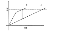
- FIG. 3 is a conceptual diagram.
- the horizontal axis is the laser irradiation time, and the vertical axis is the temperature of the laser irradiation area.
- the line A shows the characteristics of the powder containing no absorber.
- the laser irradiation starts to raise the temperature, and linearly melts above the melting point to reach the shaping temperature indicated by the broken line.
- line B shows the characteristics of the powder containing the absorber of the present invention.
- the laser irradiation causes a rapid temperature rise due to the light absorption effect of the absorber, and the effect as the absorber decreases from before the dissolution, and the temperature rise speed similar to that of the line A when the absorber is not included become.
- the powder exhibiting the characteristics of line A has poor heating efficiency, and a low density sintered part with a wide width is generated at the boundary between the solidified part and the powder in the area irradiated with laser light, and adjacent It affects the powder part in a wide range, and spatial modeling accuracy can not be obtained.
- the heating efficiency is good and the local heating can be realized. Therefore, when the laser irradiation area is formed, the temperature difference with the adjacent area can be sufficiently ensured, and only a narrow sintered part is generated at the boundary between the melted and solidified part and the powder. Modeling accuracy is obtained. Furthermore, since the formation end portion after laser irradiation does not show absorption and shows characteristics like line A, even if the process conditions fluctuate and the influence of the laser light on the existing formation area, the temperature rise by the laser light Is relatively small, and its effect can be avoided.
- the absorber of the present invention can be used without limitation as long as at least a part thereof changes to another composition having relatively low absorption by laser irradiation, but it is preferably selected from metal oxides .
- metal oxides the valence number of the metal element changes due to the release of oxygen as the temperature rises, and changes to other metal oxides with relatively low absorption to laser light (for example, Tb 4 This is because O 7 ⁇ Tb 2 O 3 and Tb 3+ tend to cause substitution of GdAlO 3 with Gd (gadolinium) site.
- the affinity with other compositions constituting the ceramic is also high, and it is possible to be incorporated into a shaped object.
- the metal oxides whose valence change functions as a change in absorptivity with respect to various laser wavelengths are Ti, V, Cr, Mn, Fe, Co, Ni, Cu, Zn, Zr, Nb, Mo, Hf, Ta It is preferable to use an oxide of a metal selected from W, In, Sn, Bi, Ce, Pr, Sm, Eu, Tb and Yb.
- YAG laser (1070 nm) which is a typical laser used for shaping, the use of oxides of Tb and Pr is preferable, and the oxidation state is Tb 4 O 7 or Pr 6 O 11 Is more preferred.
- Terbium oxide most preferable as the composition of the absorber of the present invention will be described in detail by way of example.
- Terbium oxide has various states, typically, a state called Tb 4 O 7 and a state called Tb 2 O 3 .
- Tb 4 O 7 is a substance composed of half each of Tb 4 + and Tb 3 +, but is composed of only Tb 3 + in Tb 2 O 3 .
- This high infrared absorptivity of Tb 4 O 7 is remarkable around 1070 nm of the Nd: YAG laser, and may reach over 60% and reach 70%.
- Tb 4+ decreases gradually, the absorptivity decreases, and it becomes about 7% in the Tb 2 O 3 state constituted only by Tb 3+ . Therefore, it is clear that the absorptivity decreases due to the decrease in Tb 4+ , so terbium oxide (Tb 4 O 7 ) containing tetravalent terbium in the absorber is suitable as one composition for realizing the present invention .
- Tb 4+ may be present at about 10% with respect to the total amount of Tb 3+ and Tb 4+ .
- XAFS X-ray absorption fine structure analysis
- XPS X-ray photoelectron spectroscopy
- ESR electron spin resonance
- the metal element in the case of an oxide in which the ratio of metal element to oxygen is 2: 3, the metal element is stabilized at a valence of 3+, and thus after conversion to a solidified body, another composition (for example, Y 2 O 3 or Gd 2 O 3 and others R 2 O 3 (R: metal element) exists as a solid solution. Therefore, the area converted to the solidified body after shaping does not show large absorption. Further, in a compound in which R 3 + is stable also in multi-element oxides and the like, the same state can be realized by substituting Tb at the R site. In addition, ZrO 2 forms a solid solution to contribute to the stabilization of the fluorite structure, and also in this case, the valence number is 3+. Thus, the absorber of the present invention also functions as a material constituting a shaped article.
- the absorptivity preferably has a difference of 1.2 times or more, and more preferably 2 times or more before and after performing the process by laser light irradiation.
- the absorption rate is preferably 50% or more before the process and 40% or less after the process.
- the absorption rate is preferably 60% or more before the process and 20% or less after the process.
- Tb 4 O 7 which is an example of an absorber, as a composition is preferable for achieving this situation.
- the absorptivity is that of the absorber alone.
- the absorber is contained in a plurality of compositions, the effect can be obtained, but it is more preferable that the composition which is the absorber is contained in the powder at 0.5 vol% or more and 53 vol% or less .
- vol% it is important how much area the absorber occupies with respect to the irradiation size (focus size) of the laser light, and if the composition that constitutes the powder changes, It is because it can not respond by mol% notation.
- the lower limit value of the content of the absorber is determined from the need to include at least one particle of the absorber within the laser focal size.
- the upper limit is determined from the influence on the main composition constituting the object.
- the laser focal spot size is 10 ⁇ m
- the melted area of the laser can be regarded as a hemispherical shape with a diameter of 10 ⁇ m, and one 0.5 ⁇ m diameter particle of the absorber exists in that area.
- the lower limit of the composition is preferably 0.5 vol% or more.
- Tb 3 Al 5 O 12 is formed when Tb 4 O 7 is added to Al 2 O 3 generally used as a structural ceramic.
- Tb 4 O 7 53 vol% or less, and in this case Tb 3 Al 5 O
- the upper limit value is preferably 53 vol% because a situation in which a small amount of Al 2 O 3 is dispersed in grain boundaries in the 12 main phases is realized.
- the particle size of the absorber is also important, preferably 10 ⁇ m or less, more preferably 1 ⁇ m to 10 ⁇ m, and most preferably 1 ⁇ m to 5 ⁇ m.
- the particle size in the present invention defines the range of the median value of the particle size distribution of particles composed of the same composition, and means that the particle size outside the range is not included. Absent. Further, the measurement of the grain size is applied not only to grains in a single crystal state but also to a polycrystal state and an aggregation state.
- the composition which is an absorber may constitute particles alone.
- the composition which is an absorber constitutes particles alone
- the particle size is 1 ⁇ m
- the bulk density of the powder layer is 50% of the true density
- the particle size is 10 ⁇ m
- the laser focal spot size of 100 ⁇ m corresponds to a state in which one particle is contained in the heating area, so the particle size selection of the absorber matched to the laser focal spot size is important.
- the particle spacing of each absorber is preferably 100 ⁇ m or less, more preferably 50 ⁇ m or less. It is also preferable to adjust the laser focus size so that such a situation can be realized. As described above, it is preferable that the particle diameter of the absorber is 1 ⁇ m or more and 10 ⁇ m or less as described above, assuming that the laser focal spot size is the upper limit 100 ⁇ m from the viewpoint of the shaping accuracy. However, the laser focal spot size may be 100 ⁇ m or more in accordance with the desired formation accuracy.
- the median and the shape of the particle size distribution of the particles of the composition which is a base material of the shaped object and not an absorber be spherical with 5 ⁇ m or more.
- the particle size of the absorber is in the range of 1 ⁇ m to 10 ⁇ m, the particle size is preferably as fine as possible. The reason is from the viewpoint of the dispersibility of the absorber in the powder and the high packing density.
- the particle size of the absorber is preferably 1 ⁇ 5 or less of the particle size of the composition other than the absorber.
- composition other than absorber includes a composition which is a main component as a ceramic structure. Since such a composition greatly contributes to properties such as strength in the final shaped article, it should be selected appropriately for the application. Therefore, it is preferable to select a composition which is one or more main components from metal oxides having a relatively low absorption effect by determining an absorber for the wavelength of laser light used in production. It is also preferred to select a compound or mixture.
- a composition which is one or more main components from metal oxides having a relatively low absorption effect by determining an absorber for the wavelength of laser light used in production It is also preferred to select a compound or mixture.
- aluminum oxide and zirconium oxide stabilization and metastabilization
- silicon oxide, silicon nitride and aluminum nitride can also be used.
- silicon nitride exhibits a laser absorption effect, it does not function as the absorber of the present invention because the absorptivity does not change before and after the process.
- select ceramic materials such as cordierite (2MgO ⁇ 2Al 2 O 3 ⁇ 5SiO 2 ), zircon (ZrO 2 ⁇ SiO 2 ), mullite (3Al 2 O 3 ⁇ 2SiO 2 ), yttrium oxide, aluminum titanate, etc. You can also.
- the mixture of each said material may be sufficient.
- composition as the main component may further contain small-diameter silicon oxide particles having a particle size of less than 5 ⁇ m.
- small-diameter silicon oxide particles having a particle size of less than 5 ⁇ m. The function of the silicon oxide particles is described in detail below.
- the absorber in the irradiated part absorbs energy and generates heat. Since the small diameter silicon oxide has a small particle size of less than 5 ⁇ m and is easy to melt, the heat of the absorber first melts the small diameter silicon oxide particles present around the absorber. Then, the melted small-diameter silicon oxide particles transfer heat to other relatively large particles, and the particles melt. The small-diameter silicon oxide particles melted in the laser light irradiation area soften and deform, and contact with other relatively large particles in a large area to efficiently transmit heat to the surface of the particles.
- the particle diameter of the small-diameter silicon oxide particles be smaller than the particle diameter of particles made of other compositions, and the diameter be less than 5 ⁇ m.
- the particle diameter of the small diameter silicon oxide particles is smaller than the particle diameter of each of the plural types of particles. This is because the small particle size facilitates melting along with the absorber, and the softened small-diameter silicon oxide particles are more evenly distributed than other particles, so the temperature distribution in the powder for ceramic shaping during melting Can be further reduced.
- the small-diameter silicon oxide particles are preferably spherical from the viewpoint of fluidity, but may be anisotropic shapes such as indeterminate, plate-like and needle-like.
- the small diameter silicon oxide particles preferably have a narrow particle size distribution.
- the particles can be homogeneously dispersed in the powder for ceramic formation, and when softened, they can be more uniformly distributed to the surface of particles composed of other compositions.
- the mass of the small-diameter silicon oxide particles contained in the powder for forming a ceramic is preferably 0.04% or more and 5.0% or less with respect to the mass of the particles of the absorber.
- the inclusion of 0.04% or more of SiO 2 particles is desirable because the water absorption can be made to be 1.0% or less.
- the mass of the small diameter silicon oxide particles is 5.0% or less with respect to the mass of the particles of the absorber, almost all of the small diameter silicon oxide particles existing between particles of the composition as the main component melts . It is more desirable because it does not cause melting residue that may lower the mechanical strength of the ceramic shaped article.
- the small-diameter silicon oxide particles are melted by irradiation of laser light and play a role of a heat medium, and a part thereof becomes glass and is distributed on the surface and inside of the ceramic shaped article.
- the mass of the small diameter silicon oxide particles is more preferably 1.0% or less with respect to the mass of the particles composed of the composition as the main component.
- the powder of the present invention is composed of a plurality of compositions, and preferably contains at least one component by an absorber, and at least one component of aluminum oxide, zirconium oxide and silicon oxide as main components forming a ceramic structure.
- Aluminum oxide, zirconium oxide, and silicon oxide are preferable because they have lower absorption capacity than the absorber, and they constitute a eutectic system with many material systems, and maintain high strength by the expression of their microstructure, and low
- the effect of melting can also be obtained.
- aluminum oxide when it is a mixture of two types with Tb 4 O 7 which is an absorber, it is related to Tb 3 Al 5 O 12 or TbAlO 3 with a change from Tb 4 O 7 at the time of modeling A composition is generated.
- zirconium oxide it plays a role of stabilizing zirconium oxide into tetragonal crystals in the state of Tb 3+ .
- silicon oxide be configured as a shaped object without asking for amorphous or crystal.
- silicon oxide contains not only two types of compositions with the absorber but also zirconium oxide, aluminum oxide and the like, and be composed of three components and four components. Furthermore, zircon, mullite, silicate with an absorber, etc. may be contained in the silicon oxide-containing shaped article.
- a plurality of compositions be contained in a relation of forming a eutectic composition.
- the eutectic composition is the composition at the eutectic point shown in the eutectic phase diagram, but since the shaping process using the laser light of the present invention is repeatedly heated and cooled at a very high speed, from the equilibrium state It's extremely different. Therefore, it is preferable to define the eutectic composition as the composition range in which the eutectic structure is formed, and the range of ⁇ 10 mol% from the eutectic composition in the eutectic phase diagram is acceptable.
- At least one or more rare earth oxides that are not absorbers are included.
- the metal element of the rare earth oxide is preferably selected from Sc, Y, La, Ce, Nd, Sm, Eu, Gd, Dy, Ho, Er, Tm, Yb, Lu.
- RAlO 3 or R 3 Al 5 O 12 or the like may be formed with respect to R 2 O 3 (or RO 2 in some cases) depending on the composition, and a new composition is formed between the compositions. Where possible, it is also preferred to use the composition. In some cases, it is also preferred that the composition be a eutectic composition.
- material systems consisting of Tb 3+ and Pr 3+ are also applicable.
- molding of this invention is used in the manufacturing process (manufacturing method) of the molded article by irradiation of a laser beam.
- the manufacturing process includes (i) disposing the above-described powder for ceramic formation of the present invention in a portion irradiated with laser light, and (ii) irradiating the powder for ceramic formation on the basis of three-dimensional formation data.
- the ceramic powder has a step of sintering or melting and then solidifying it, and (iii) a step of repeating the steps (i) and (ii) to form a shaped object.
- sintering or melting and solidification in the present invention is not unique as sintering when the powder is not melted at all, and melting when there is no unmelted powder.
- liquid phase sintering and the area of each term is obscured. Therefore, from the degree of sintering that bonds the powders, liquid phase sintering in which the melt is present so as to surround the powder, and also dissolution in which the powder that is partially melted remains is also interpreted The above is not excluded.
- the heating means is not limited, and can be selected and used according to the purpose, such as a resistance heating method, an induction heating method, an infrared lamp method, a laser method, and an electron beam method.
- the heat treatment is also suitable for adjusting the crystal grain size of the shaped object for the purpose of improving the density and strength of the shaped object.
- the steps (i) and (ii) may be performed by irradiating a laser beam after the powder of the present invention is spread. Further, the steps (i) and (ii) may be performed by ejecting the powder of the present invention to a predetermined location and irradiating the predetermined position with a laser beam.
- a so-called powder bed fusion bonding method or a cladding method corresponds to a method of obtaining a shaped object by repeating sintering or melting and solidifying successively in a portion irradiated with a laser beam.
- a lens or a fiber adjusted to a desired focal point size such as 10 ⁇ m to 2 mm.
- the focal point size is one of the parameters that affect the formation accuracy, and in order to satisfy the formation accuracy of 0.1 mm, although depending on the situation, the line width is preferably the same degree, and the focal point size is 100 ⁇ m or less Is preferred.
- Irradiation of the laser light may be continuous or pulsed.
- One example is an Nd: YAG laser, and the wavelength is around 1070 nm.
- the powder bed fusion bonding process is described with reference to FIG.
- the apparatus used for this method includes a powder crucible 11, a shaping stage unit 12, a recoater unit 13, a scanner unit 14, a laser light source 15, and the like.
- the powder is operated by the recoater unit 13 while the powder crucible 11 and the shaping stage unit 12 move up and down appropriately, and the powder is spread evenly in a region wider than the assumed modeled object.
- the powder layer is directly drawn by the laser light generated from the laser light source 15 and the scanner unit 14 in one cross-sectional shape of the shaped object.
- the drawn area is sintered or melted to cause solidification, and in this repetition, the cross sections of the shaped object are laminated to form the final shaped object.
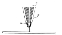
- the cladding method is described with reference to FIG. A method in which powder is ejected from a plurality of powder supply holes 22 in the cladding nozzle 21 and laser light 23 is irradiated to a region where the powder is focused to sequentially form a three-dimensional object at a desired location. It is characterized in that it can be shaped on a curved surface or the like.
- Example 1 A present Example is related with the improvement of the modeling precision by containing the absorber of this invention.
- the powder bed of 1.5 mm in thickness was melted and solidified by irradiation of a laser beam, and the state observation of the irradiated part of the laser beam and the non-irradiated part was performed.
- Sample 1 is a mixed powder of Al 2 O 3 powder, Gd 2 O 3 powder, and Tb 4 O 7 powder (composition ratio: Al 2 O 3 : 64.40 vol%, Gd 2 O 3 : 32.73 vol%, Tb 4 O 7 : 2.87 vol%) is configured as a powder bed of 1.5 mm thickness, Nd: YAG laser (1070 nm) focal diameter 100 ⁇ m, laser power 30 W, laser beam irradiation speed 100 mm / sec, 250 mm / sec The lines of 10 mm in length were irradiated at 40 ⁇ m at a pitch of 50 ⁇ m at two different speeds.
- Tb 4 O 7 An example of the absorber adopted here, Tb 4 O 7 , is in a state of including not only Tb 3+ but also Tb 4+ . Moreover, in volume composition calculation, Al 2 O 3 : 3.96 [g / cm 3 ], Gd 2 O 3 : 7.40 [g / cm 3 ], Tb 4 O 7 : 7.60 [true density]. g / cm 3 ] was used. Even if this true density is a somewhat different value, it does not affect the essence of the present invention.
- Comparative sample 1 contains no absorber, and comparative sample 2 is present in a form in which Tb is substituted for the Gd 3+ site of GdAlO 3 , and Tb 4+ hardly exists and the absorption effect disappears .
- these two comparative samples having no absorber effect they were almost in the powdery state under the irradiation condition of laser light of 250 mm / sec, and a tissue solidified at 100 mm / sec and then solidified was clearly obtained.
- the in-plane nonuniformity in the heated state is large, and a shaped object of a two-dimensional surface can not be obtained even as a solidified body, and locally melted and solidified grains are rolled. .
- Sample 1 showed sufficient dissolution from 250 mm / sec, and it could be confirmed that a two-dimensional structure was formed in a planar shape.
- the Tb 4 O 7 is taken into the Gd site of GdAlO 3 as Tb 3 + , and the shaped object in the irradiated portion reaches a state where the absorption effect similar to Comparative Sample 2 is low.
- the sample 1 is mixed with the powder in the state of 60% or more of the absorptivity, and after irradiation of the laser light, the absorption is less than 30% because almost no tetravalent exists from fluorescence observation.
- the absorptivity was 30% or less from the powder state before shaping from fluorescence observation, and there was no change even after the irradiation of the laser light, and it was 30% or less.
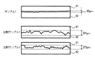
- FIG. 4 shows the result of calculating the swing width of the outline of the boundary portion by cutting out an image with a width of 3.83 mm from the micrograph of the boundary between the irradiated region 42 and the non-irradiated region 41 of the laser light.
- Comparative sample 1 was 391 ⁇ m wide
- comparative sample 2 was 273 ⁇ m wide
- sample 1 was 85 ⁇ m wide.
- sample 1 since the area after shaping of sample 1 and the powder of comparative sample 2 are in the same state in terms of the effect of the absorber, sample 1 has a 250 mm / mm with respect to the powder area where the absorber functions. It became clear that it could form by sec and the area after formation hardly functions at 250 mm / sec.
- the sample of the present invention is excellent in modeling accuracy relative to the comparative sample, and a shaped object can be obtained without disturbing the area where the process is completed again.
- Tb 4 O 7 of the metal oxide which is an example of the absorber contains 4+ in valence
- the absorption characteristics are changed due to the valence reduction to 3+ in the region after formation.
- the irradiation conditions of the laser light are not limited to only the values described in the present embodiment because they are changed according to the surrounding environment, the material configuration, the thickness of the powder layer, and the like.
- Example 2 The present example relates to the addition effect of Tb 4 O 7 which is a candidate of an absorber.
- Tb 4 O 7 has a value of 60% or more as an absorptivity at around 1070 nm, and when it is only a Tb 3+ state such as Tb 2 O 3 , the absorptivity is 30% or less.
- a mixed powder of Al 2 O 3 powder, Gd 2 O 3 powder, and Tb 4 O 7 powder as the sample 1 composition ratio is Al 2 O 3 : 64.40 vol%, Gd 2 O 3 : 32 .73vol%, Tb 4 O 7: 2.87vol%) and was used, the samples 2, 3, 4, 5, and Comparative sample 3 was formulated as in table 1 was added thereto. At this time, the particle diameter of the Tb 4 O 7 powder was about 2 ⁇ m.
- These powders were spread on an Al 2 O 3 substrate to a thickness of about 20 ⁇ m and then irradiated with a Nd: YAG laser.
- the conditions were 12 lines with a focal length of 20 ⁇ m, 10 W, 50 mm / sec, and 4.5 mm length at 50 ⁇ m pitch.
- the width of the boundary between the irradiated area of the laser beam and the unirradiated area was observed in the range of 2 mm in width.
- the results are shown in Table 1.
- the blending amount (vol%) of each composition, the width ( ⁇ m) of the boundary portion, and the effect of Tb 4 O 7 addition are represented as excellent ⁇ , good ⁇ , and ⁇ .
- the width (swinging width) of the boundary is an index substantially equivalent to the surface roughness of the side surface of the shaped object, and the larger the width, the rougher the surface of the manufactured shaped object.
- the standard surface roughness of a shaped article manufactured using metal powder is said to be about ten and several ⁇ m. Therefore, the equivalent case is evaluated as ⁇ .
- the same criteria are used in the other examples.
- Example 3 This example relates to the addition effect of Pr 6 O 11 (praseodymium oxide), which is a candidate of an absorber. It has an absorption of 80% or more at around 1070 nm in the state of valence near Pr 6 O 11 or 10 10 nm, and has an absorption of 50% or less when there are many Pr 3+ states such as Pr 2 O 3 .
- Sample 6 is a mixed powder of Al 2 O 3 powder, Gd 2 O 3 powder, and Pr 6 O 11 powder (composition ratio: Al 2 O 3 : 63.85 vol%, Gd 2 O 3 : 33.29 vol%, Pr 6 O 11 : 2.86 vol%) was used. At this time, the particle diameter of the Pr 6 O 11 powder was about 2 ⁇ m.
- these powders were spread on an Al 2 O 3 substrate to a thickness of about 20 ⁇ m and then irradiated with an Nd: YAG laser.
- the conditions were 12 lines with a focal length of 20 ⁇ m, 10 W, 50 mm / sec, and 4.5 mm length at 50 ⁇ m pitch.
- the width of the boundary between the irradiated area of the laser beam and the unirradiated area was observed in the range of 2 mm in width.
- the results are shown in Table 2.
- the compounding amount (vol%) of each composition was as described above, the width of the boundary was 42.7 ⁇ m, and the effect of Pr 6 O 11 addition was good ⁇ .
- the width of the boundary is shown to be narrower than that of Comparative Sample 3 of Example 2, and when Pr 6 O 11 which is an example of the absorber of the present invention is added, the judgment result shown in Table 2 is obtained. It turned out that the effect that modeling accuracy improves with respect to the case of addition is acquired.
- Example 4 The present example relates to the effect of the absorber on compositions other than the absorber.
- the compositions investigated are shown in Table 3.
- Al 2 O 3 3.96 [g / cm 3 ], ZrO 2 : 5.68, Y 2 O 3 : 5.01 [g / cm 3 ], Tb 4 O 7 as true density. : 7.60 [g / cm ⁇ 3 >] was used. Even if this true density is a somewhat different value, it does not affect the essence of the present invention. Powders containing these compositions were spread on an Al 2 O 3 substrate to a thickness of about 20 ⁇ m and then irradiated with laser light.
- the conditions were as follows: The focus size was 100 ⁇ m, 30 W, and a 4.5 mm long line was drawn at a 50 ⁇ m pitch at a scanning speed of 50, 100, 200, 500 mm / sec for comparison of the molten states.
- the pure Al 2 O 3 of Comparative Sample 4 could be melted and solidified in a line to 100 mm / sec, but could be up to 500 mm / sec for Sample 7 to which the absorber was added.
- the pure ZrO 2 of Comparative Sample 5 was in a state where it could be melted and solidified in a line shape up to 100 mm / sec, but with Sample 8 to which the absorber was added, it could be up to 500 mm / sec.
- comparative sample 6 in the vicinity of the eutectic composition Al 2 O 3 -ZrO 2 system has been in a state which can be solidified by melting in a line to 200 mm / sec, the sample 9 were added to the absorber, 500 mm / It was possible to sec.
- Comparative Sample 7 near the eutectic composition of the Al 2 O 3 -Y 2 O 3 system was in a state where it could be melted and solidified in a line shape up to 200 mm / sec, but in Sample 10 to which an absorber was added, Up to 500 mm / sec was possible.
- Example 5 The present example relates to 3D formability when the absorber is contained.
- Each particle diameter of the composition which comprises the powder used by a present Example is shown to Table 4, 5.
- the particles of these compositions used were spherical except for Tb 4 O 7 and Pr 6 O 11 which function as absorbers.
- Tables 6 and 7 show the volume compositions of the implemented material systems.
- ProX (trade name) series DMP 100 of 3D systems was used as a modeling apparatus.
- a shaped product of 6 ⁇ 6 ⁇ 6 mm was produced under the forming conditions shown in Table 8 for Comparative Sample 8 not containing an absorber, and Samples 11 to 24 composed of a plurality of compositions containing an absorber.
- the thickness of the powder layer was 20 micrometers and the base material used the alumina board. The thickness of the powder layer is a value for lowering the shaping stage portion 12 of FIG.
- the apparent thickness of the powder layer is As the lamination is repeated, the thickness gradually increases and converges in the range of 67 to 133 ⁇ m. Therefore, although the average particle diameter of the composition of Tables 4 and 5 is larger than 20 micrometers of powder layers at the time of shaping
- the surface roughness Ra was measured using Alpha-step (trade name) manufactured by KLA Tencor Co., Ltd., and the modeling accuracy was confirmed. Because the roughness is relatively greater on the side than on the surface of the object, the evaluation was made on the side.
- the scan width at the time of calculation is 1 mm.
- Comparative Sample 8 which does not contain the absorber of the present invention, although it is partially dissolved as in Comparative Sample 1 of Example 1, the shape as a shaped object is maintained as a result of additive manufacturing. could not.
- the other samples 11 to 24 were densely formed as layered products, and it was possible to measure the surface roughness of the side surface. It has been shown that the absorber of the present invention can improve the surface roughness, in particular, obtain a shaped object suppressed to about several tens of ⁇ m, and can be shaped with high accuracy.
- Example 6 This example relates to the case where the composition other than the absorber is an individual particle and the case where the composition is the same particle. Comparison of sample 13 of Example 5 with a sample in which Al 2 O 3 and Gd 2 O 3 are eutectic powder (mixed state of Al 2 O 3 and GdAlO 3 ) and mixed with Tb 4 O 7 , and the sample 15 and Al 2 O 3 and Y 2 O 3 were eutectic powders (a mixed state of Al 2 O 3 and Y 3 Al 5 O 12 ), and a comparison was made with a sample in which Tb 4 O 7 was mixed.
- Example 5 As in Example 5, a ProX (trade name) DMP 100 manufactured by 3D systems was used as a modeling apparatus. Under the modeling conditions of Table 11, a 6x6x6 mm shaped article was produced. The following judgment was made about the formability. No shape: Bad x, roughening on the surface or side: Slightly bad ⁇ A shaped object according to the specified dimensions can be obtained: Good ⁇ . Moreover, in all, the thickness of the powder layer was 20 micrometers and the base material used the alumina board.
- Example 7 This embodiment relates to an example of the tolerance to the change of the irradiation condition of the laser beam when the absorber of the present invention is used.
- a mixed powder of Al 2 O 3 powder, Gd 2 O 3 powder, Tb 4 O 7 powder, which is the powder composition of sample 13 of Example 5 (composition ratio is Al 2 O 3 : 64.40 vol%, Gd 2 O 3 : 32.73 vol%, Tb 4 O 7 : 2.87 vol%) was used, and ProX (trade name) DMP 200 manufactured by 3D systems was used as a modeling apparatus.
- the laser light irradiation speed was 500 mm / s
- the laser light irradiation line pitch was fixed at 130 ⁇ m
- the laser power was changed
- the energy density at the time of modeling was increased or decreased.
- the thickness of the powder layer was 25 ⁇ m
- an alumina plate was used as a substrate.
- a 6x6x6 mm shaped object was produced with the laser power shown in Table 12, and the following determination was made regarding its formability. No shape: Bad x, roughening on the surface or side: Slightly bad ⁇
- a shaped object according to the specified dimensions can be obtained: Good ⁇ .
- Example 8 The present example is an example in which SiO 2 particles are added.
- molding of a present Example was manufactured in the following procedures.
- the main components are mixed Al 2 O 3 powder (purity 99.99% or more, particle size 20 ⁇ m) and Gd 2 O 3 powder (purity 99.99% or more, particle size 20 ⁇ m) in a mass ratio of 1: 1. I used what I did.
- Tb 4 O 7 powder purity 99.9% or more, particle diameter 4 ⁇ m
- the SiO 2 particles used had a purity of 99.9% or more and a particle diameter of 4 ⁇ m.
- Example 27 Each powder was weighed so that the particles forming the main component, the particles forming the absorber, and the SiO 2 particles had a mass ratio of 96.4: 3.5: 0.14.
- the weighed powder was mixed in a dry ball mill for 30 minutes to obtain a mixed powder (powder for forming a ceramic) (Sample 27).
- the powder for ceramic formation was dissolved by heating with dilute sulfuric acid, and composition analysis was performed by ICP emission spectrometry.
- the mass ratio of Al 2 O 3 , Gd 2 O 3 , Tb 4 O 7 and SiO 2 was 48.2: 48.2: 3.5: 0.14, which was the same as the feed composition ratio.
- the content of the other components was less than 0.2% by mass with respect to the powder for ceramic formation.
- Example 9 to 25 In the same manner as in Example 8 except that the raw material type and the compounding ratio were changed according to Table 13, powders for shaping a ceramic of Samples 28 to 44 were manufactured as Examples 9 to 25.
- zirconium oxide ZrO 2 powder (purity 99.9% or more, particle diameter 15 ⁇ m) was used.
- Praseodymium oxide Pr 6 O 11 powder (purity 99.9% or more, particle diameter 4 ⁇ m) was used.
- the compositions of the powders for ceramic formation of Samples 28 to 44 were analyzed in the same manner as in Example 8.
- a powder for ceramic formation for comparison was manufactured in the same manner as Example 8.
- the powder for forming a ceramic for comparison is configured only with Al 2 O 3 and Gd 2 O 3 and Tb 4 O 7 which is particles serving as an absorber without using SiO 2 particles.
- the mass ratio of Al 2 O 3 , Gd 2 O 3 , and Tb 4 O 7 was the same as the preparation composition ratio.
- SiO 2 was less than 50 ppm based on the powder for ceramic formation for comparison.
- the content of the other components was less than 0.2% by mass with respect to the powder for ceramic formation.
- Ceramic shaped articles were formed using the powders for ceramic shaping in Examples 8 to 25 and Comparative Example.
- ProD (trade name) series DMP 100 of 3D SYSTEMS in which a 50 W Nd: YAG laser (beam diameter 65 ⁇ m) is mounted, was used.
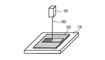
- the powder for ceramic formation is spread on the laser irradiation portion on the base 130 made of alumina, and the first powder layer 102 having a thickness of 20 ⁇ m is obtained. Formed.
- the powder layer was irradiated with a laser beam 180 of 30 W from a laser source 181 to melt and solidify the powder in a 5 mm ⁇ 42 mm rectangular area.
- the drawing speed was 100 mm / s to 140 mm / s, and the drawing pitch was 100 ⁇ m.
- the drawing line was made to be 45 degrees diagonal to the side of the rectangle.
- a powder layer having a thickness of 20 ⁇ m was newly spread to cover the melted and solidified portion.
- the powder layer immediately above the rectangular area was irradiated with a laser beam so as to be orthogonal to the drawing line of the first layer, and the area of 5 mm ⁇ 42 mm was melted and solidified.
- Such a lamination molding process was repeated to form a prismatic shaped object having a bottom surface of 5 mm ⁇ 42 mm and a height of 6 mm for use in the three-point bending strength test.
- a square column shaped body with a square of 22 mm square and a height of 12 mm was also formed for the water absorption test.
- the irregularities on the surface of the model are 30 ⁇ m or less, the sample 40, and the sample 41 for the samples 27 to 39 and samples 42 to 44. And 40 ⁇ m or less in the shaped article of Comparative Sample 9.
- the shaped object is separated from the base made of alumina, and by grinding, a ceramic shaped object of W40 mm ⁇ D4 mm ⁇ H3 mm (FIG. 6A) for a three-point bending strength test, and W20 mm ⁇ D20 mm ⁇ H10 mm ceramic shaping for a water absorption test
- the thing (FIG. 6B) was obtained.
- a compression tester manufactured by Instron was used for the three-point bending test. Table 15 shows the three-point bending strengths of the ceramic shaped articles of the examples and the comparative example 1.
- the mass w1 [g] of the absolutely dried ceramic shaped article dried at 80 ° C. for 4 hours was measured.
- the ceramic shaped article was submerged under the water surface of the boiling tank and boiled for 30 minutes, then water was added and the mixture was cooled to room temperature to obtain a saturated sample.
- the water sample was taken out of the water, and the surface was quickly wiped with wet gauze to remove water droplets, and the mass w2 [g] of the ceramic shaped article in a surface-dried and water-saturated state was measured.
- the ceramic shaped article produced from the powder for ceramic shaping in Examples 8 to 25 had a high 3-point bending strength of 20 MPa or more in 3-point bending strength, and the water absorption rate was as small as 1.0% or less.
- ceramic shaped articles of samples 27, 28, 30 to 36, 38, 39, 42 to 44 satisfying ⁇ ⁇ 1.0, 0.04 ⁇ ⁇ ⁇ 5, ⁇ ⁇ 20 have a high three-point bending of 25 MPa or more It had strength.
- the powder for ceramic shaping of the present invention can obtain a ceramic shaped article with high shaping accuracy by addition of an absorber in the powder bed fusion bonding method or cladding method, and in the ceramic component field requiring a complicated shape It is available.
Abstract
Provided are: a powder for laser shaping that is capable of stable shaping and makes it possible to obtain a three-dimensional shaped article with ensured shaping precision; and a method for using the powder for laser shaping. A powder for ceramic shaping is for obtaining a shaped article by repetition of successive sintering or melting and solidification of the powder by a laser light irradiation unit, wherein: the powder includes a plurality of compositions; at least one type of composition from among the compositions is an absorbent body that shows relatively higher absorption of the laser light than the other compositions; and at least part of the absorbent body is changed in response to irradiation with the laser light into another composition with a relatively lower rate of absorption of the laser light.
Description
本発明は、レーザー照射によりセラミックス造形物を形成する際に使用する粉体およびその粉体を使用した製造方法に関する。
The present invention relates to a powder used when forming a ceramic shaped article by laser irradiation and a manufacturing method using the powder.
近年、付加造形技術が伸展し、特に金属分野では、粉末床溶融結合法(powder bed fusion)において緻密で多様性のある造形物が実現されている。その緻密性は、効果的に溶融させて凝固組織群として造形物が得られることに起因する。このような状況において、セラミックス造形への展開性も議論され、多くの取り組みが報告されている。セラミックスを金属同様に溶融させるためには、相応のエネルギーを投入する必要があるが、金属とは異なり粉体内での光拡散も伴って均一な溶融が達成できず、造形精度を得ることが難しい状況にあった。そのため、溶融させず焼結に留めることで、造形精度を確保する方向で造形物が形成されたが、緻密さに欠けていた。
In recent years, additive fabrication techniques have been developed, and in the metal field in particular, compact and versatile shaped objects have been realized in powder bed fusion. The compactness results from the fact that they are effectively melted to obtain a shaped article as a solidified tissue group. Under such circumstances, the applicability to ceramic molding has also been discussed, and many approaches have been reported. In order to melt ceramics in the same way as metals, it is necessary to apply appropriate energy, but unlike metals, it is difficult to achieve uniform melting with light diffusion in powder, and it is difficult to obtain modeling accuracy I was in a situation. Therefore, although a shaped article was formed in the direction for securing the shaping accuracy by fixing it to sintering without melting, it was lacking in compactness.
このような状況において、例えば、非特許文献1では、Al2O3―ZrO2共晶系を用いることで融点を下げ、かつ溶融して凝固した時に共晶系特有の微細構造を形成させ高い機械強度も実現する手法が提案されている。しかし、造形物の緻密さを向上させる点は満たすことに成功しているが、造形物の表面に多数の突起物が発生しており、十分な造形精度に達している状況ではなかった。
Under such circumstances, for example, in Non-Patent Document 1, the melting point is lowered by using an Al 2 O 3 -ZrO 2 eutectic system, and when it is melted and solidified, a microstructure unique to the eutectic system is formed to be high. Methods have also been proposed to realize mechanical strength. However, although it has succeeded in satisfying the point of improving the compactness of a shaped object, a large number of projections are generated on the surface of the shaped object, and the situation has not reached a sufficient modeling accuracy.
レーザー光の波長はNd:YAG(約1μm)であり、共晶系で低融点化したとしてもAl2O3もZrO2も明瞭な吸収を示さないため、当該材料系を溶融して凝固させるためには、相応のエネルギーを必要とする。このような系では、粉体中の光拡散も伴い、所望の造形部分での不均一な溶融や、その周辺での不均一な焼結領域が幅広く生じるなどの課題があった。
The wavelength of the laser light is Nd: YAG (about 1 μm), and neither Al 2 O 3 nor ZrO 2 show clear absorption even if the melting point is lowered in the eutectic system, so the material system is melted and solidified. In order to do that, you need some energy. In such a system, there are problems such as nonuniform melting in a desired shaped portion and wide nonuniform sintering region around the desired shape, accompanied by light diffusion in powder.
さらに、レーザースキャン中の近接領域や積層方向など、既にプロセス完了済みの箇所が再度のレーザー光の吸収で加工されてしまうこともあり造形精度に悪影響を与えるという課題があった。
Furthermore, there is also a problem that the processing accuracy is adversely affected because the processing completed area is processed by absorption of the laser beam again, such as the proximity region during the laser scan and the stacking direction.
したがって、造形精度向上のためには、粉体における光拡散を抑制できる、レーザー波長の吸収を示すとともに、レーザー光を再吸収して影響を受けないように、一度造形した箇所の吸収効果が低減ないし消失する材料が求められていた。
Therefore, to improve the shaping accuracy, it is possible to suppress light diffusion in the powder, show absorption of the laser wavelength, and reduce the absorption effect of the once formed portion so as not to be affected by re-absorption of the laser light. There was a need for a material that would disappear.
本発明のセラミックス造形用粉体は、レーザー光の照射部における粉体を逐次焼結または溶融して凝固させることを繰り返して造形物を得るためのセラミックス造形用粉体であって、前記粉体は複数の組成物を含み、前記組成物の少なくとも1種類の組成物が、前記レーザー光に対し他の組成物より相対的に高い吸収を示す吸収体であり、前記レーザー光の照射により前記吸収体の少なくとも一部が、前記レーザー光に対する吸収が相対的に低い他の組成物に変化することを特徴とする。
The powder for ceramic formation of the present invention is a powder for ceramic formation for obtaining a shaped article by repeatedly sintering or melting and solidifying the powder in a portion irradiated with a laser beam successively, Is an absorber comprising a plurality of compositions, at least one composition of said composition exhibiting an absorption relatively higher for said laser light than the other compositions, said absorption resulting from the irradiation of said laser light It is characterized in that at least a part of the body changes to another composition having relatively low absorption to the laser light.
また、レーザー光の照射部における粉体を逐次焼結または溶融して凝固させることを繰り返して造形物を得るセラミックス造形物の製造において、
(i)上記のセラミックス造形用粉体をレーザー照射部に配置する工程、
(ii)前記セラミックス造形用粉体に3次元造形データに基づいてレーザーを照射することにより、前記セラミックス造形用粉体を焼結または溶融させた後に凝固させる工程、および
(iii)前記工程(i)と(ii)を繰り返して造形物を製造する工程、
を有することを特徴とする。 Further, in the production of a ceramic shaped article in which a shaped article is obtained by repeating sintering or melting and solidifying powder sequentially in a portion irradiated with laser light to obtain a shaped article,
(I) disposing the above-mentioned powder for ceramic formation in a laser irradiation part,
(Ii) applying a laser to the powder for ceramic formation based on three-dimensional formation data to sinter or melt the powder for ceramic formation and then solidify; and (iii) the step (i) ) And (ii) to produce a shaped article,
It is characterized by having.
本発明のセラミックス造形用粉体を用いれば、レーザー光の照射により吸収体の一部が前記レーザー光に対する吸収が相対的に低い他の組成物に変化することにより、焼結或いは溶融後の領域は以後の造形時におけるレーザー照射の影響を受け難くなる。また、その吸収体は、前記レーザー光に対する吸収が、粉体を構成する他の組成物より相対的に高いため光拡散も低減できる。結果、造形精度の高いセラミックス造形物の製造を実現することができる。
When the powder for ceramic formation of the present invention is used, a region after sintering or melting is obtained by changing a part of the absorber to another composition having relatively low absorption with respect to the laser light by laser light irradiation. Is less susceptible to laser irradiation during subsequent shaping. In addition, the absorber can also reduce light diffusion because the absorption with respect to the laser light is relatively higher than that of the other composition constituting the powder. As a result, it is possible to realize production of a ceramic shaped article with high shaping accuracy.
以下、図面を参照して本発明を実施するための形態を説明する。まず、本発明における粉体と組成物、吸収体について説明する。粉体とは、孤立した粒と認識できる粒子の集合体である。また、粉体は複数の組成物からなる。なお、組成物とは、複数の成分(元素或いは化合物)から構成されたものである。また、粉体が複数の組成物からなるとは、1種類の組成物からなる粒子が多種類混在している場合、或いは複数種の組成物からなる粒子が1種類、或いは多種類混在している場合を意味する。吸収体は、使用されるレーザー光に対し粉体を構成するほかの組成物に比べ相対的に高い吸収能を有する組成物として規定される。言い換えると、吸収体は、粉体に含まれる組成物の中でレーザー光に対する吸収能が最も高い。本発明の粉体を構成する少なくとも1種類の組成物が、レーザー光の吸収能がある吸収体である。吸収体の吸収能は使用される波長のレーザー光に対し、10%以上の吸収率であることが好ましい。また、吸収率が40%以上である場合はより好ましく、さらに60%以上である場合が最も好ましい。吸収体単体の吸収率の測定方法としては、一般的な分光計を用いればよく、積分球を用いて、試料皿に充填した吸収体単体に想定波長(製造で使用されるレーザー波長近傍)を照射して計測する。試料の無い場合を参照データとして、その比率から吸収率を算出するものである。
Hereinafter, embodiments of the present invention will be described with reference to the drawings. First, the powder, the composition, and the absorber in the present invention will be described. Powder is an aggregate of particles that can be recognized as isolated particles. Moreover, powder consists of several compositions. The composition is composed of a plurality of components (elements or compounds). In addition, powder is composed of a plurality of compositions, when many kinds of particles consisting of one kind of composition are mixed, or one kind or many kinds of particles consisting of plural kinds of composition are mixed I mean the case. The absorber is defined as a composition having a relatively high absorption capacity for the laser light used as compared to other compositions constituting the powder. In other words, the absorber has the highest ability to absorb laser light among the compositions contained in the powder. At least one composition constituting the powder of the present invention is an absorber capable of absorbing laser light. The absorptivity of the absorber is preferably an absorptivity of 10% or more for the laser light of the wavelength used. The absorption rate is more preferably 40% or more, and still more preferably 60% or more. As a method of measuring the absorptivity of an absorber alone, a general spectrometer may be used, and an integrator alone is used to measure the assumed wavelength (near the laser wavelength used in manufacturing) to the absorber alone filled in the sample plate. Irradiate and measure. The absorptivity is calculated from the ratio using the case where there is no sample as reference data.
(粉体)
本発明の粉体は、2種類以上からなる複数の組成物で構成され、複数の組成物は吸収体である組成物を少なくとも1種類含む。粉体を構成する各粒子は単一の組成物からなっていても良いし、一つの粒子が複数の組成物からなっていても良い。以下に場合分けをして、順に説明する。 (powder)
The powder of the present invention is composed of a plurality of compositions of two or more types, and the plurality of compositions include at least one composition which is an absorber. Each particle constituting the powder may consist of a single composition, or one particle may consist of a plurality of compositions. The following will be described in order by case.
まず、粉体が単一の組成物からなる粒子で構成されている状態の場合である。一例として、複数の組成物が、Al2O3、ZrO2、Tb4O7(吸収体)の3種類で構成されている場合、Al2O3粒子、ZrO2粒子、Tb4O7粒子がそれぞれ存在し、それらの粒子の混合物として粉体が構成されている状態が挙げられる。
First, it is the case where the powder is composed of particles consisting of a single composition. As an example, when a plurality of compositions are composed of three types of Al 2 O 3 , ZrO 2 , and Tb 4 O 7 (absorber), Al 2 O 3 particles, ZrO 2 particles, Tb 4 O 7 particles Are present, and the powder is constituted as a mixture of those particles.
次に、粉体が2種類以上の組成物から構成される粒子を含んでいる状態の場合である。一例として、組成物が、Al2O3、ZrO2、Tb4O7(吸収体)の3種類で構成されている場合、Al2O3-ZrO2-Tb4O7からなる粒子のみで構成されている状態や、Al2O3-ZrO2粒子、Tb4O7粒子と言うように、Al2O3-ZrO2が同一粒子を構成しているような状態である。特に、吸収体を他の組成物と同じ粒子に含有させて構成する場合には、本発明の吸収体の一例であるTb4O7においては、Tb4O7状態を維持して構成することが好ましい。さらに、吸収体である組成物は、その他の組成物がどのように構成されていようとも、単独で粒子を構成している状況が好ましい。
Next, it is a case where the powder contains particles composed of two or more kinds of compositions. As an example, the composition, Al 2 O 3, ZrO 2 , Tb 4 O 7 when configured in three (absorbers), only particles made of Al 2 O 3 -ZrO 2 -Tb 4 O 7 and the condition being constituted, Al 2 O 3 -ZrO 2 particles, as saying that Tb 4 O 7 particles, a state such as Al 2 O 3 -ZrO 2 belong to the same particles. In particular, when the absorber is contained in the same particles as other compositions, the Tb 4 O 7 which is an example of the absorber according to the present invention should be maintained in the Tb 4 O 7 state. Is preferred. Furthermore, the composition which is an absorber is preferable in the condition where it constitutes particles alone, regardless of how the other compositions are constituted.
また、本発明の粉体においては、粉末床溶融結合法でリコーターを用いて粉末ベッド層を構成する場面や、クラッディング法におけるノズルからの粉体噴射をする場面における粉体の流動性が重要である。粉体は、流動性指標として40[sec/50g]以下を満たすような粉体を用いることが好ましい。流動性を確保するためには、粒子は球形であることが好ましい。ただし、上記流動性指標を満たせば、球形であることは必須ではない。
Moreover, in the powder of the present invention, the flowability of the powder is important in the case where a powder bed layer is formed using a recoater by a powder bed fusion bonding method, and in the case where powder is sprayed from a nozzle in cladding method. It is. As the powder, it is preferable to use a powder that satisfies 40 [sec / 50 g] or less as a fluidity index. In order to ensure fluidity, the particles are preferably spherical. However, spherical shape is not essential if the above liquidity index is satisfied.
さらに、吸収体を構成する組成物の粒子の粒径(粒径とは、単一粒子のものではなく同一組成を成している粒子群の中央値とする)が、吸収体でない組成物の粒子の粒径の1/5以下であることが好ましい。よって、吸収体を構成する粒子の粒径が1μm以上10μm以下であることが好ましいから、吸収体以外の組成物の粒径は5μm以上で上記条件を満たすことが重要である。
Furthermore, the particle size of the particles of the composition constituting the absorber (the particle size is not the single particle but the median value of the particles having the same composition, but not the single particle) It is preferable that it is 1/5 or less of the particle size of particle | grains. Therefore, since it is preferable that the particle size of the particle which comprises an absorber is 1 micrometer or more and 10 micrometers or less, it is important for the particle diameter of compositions other than an absorber to be 5 micrometers or more, and the said conditions satisfy | fill.
また、本発明の粉体は、樹脂バインダーを含有していないことが好ましい。樹脂バインダーを含有する場合には、レーザー照射で爆発的に焼失する過程が発生する場合があり、造形領域に空孔等を内在させる原因となる可能性があるためである。さらに、炭素が含有されていると酸素と結合し気体となる上に、炭素成分が占めていた体積が空孔となるおそれがあるため、少ないことが好ましい。従って、炭素の含有は、粉体を構成する複数の組成物の金属元素に対してモル比で1000ppm以下であることが好ましい。
また、炭素が含有されているとレーザー照射により酸化し、ガス化して造形に悪影響を与えるため、本発明の吸収体のようにレーザー照射により異なる組成物への変化を伴い造形物中に取り込まれることが好ましい。 Moreover, it is preferable that the powder of this invention does not contain the resin binder. When the resin binder is contained, a process of explosively burning away may be generated by laser irradiation, which may cause internal inclusion of pores and the like in the modeling region. Furthermore, if carbon is contained, in addition to being combined with oxygen to form a gas, the volume occupied by the carbon component may be vacancies, so the amount is preferably small. Therefore, the content of carbon is preferably 1000 ppm or less in molar ratio with respect to the metal elements of the plurality of compositions constituting the powder.
In addition, if carbon is contained, it is oxidized by laser irradiation and oxidized to gasify and adversely affect the formation, so it is incorporated into a formed article with a change to a different composition by laser irradiation like the absorber of the present invention Is preferred.
ここまで吸収体と組成物と粒子について記述してきたが、本発明におけるセラミックス造形用粉体は結晶や非晶質状態であるか、それらの混合物であるかなどを一切問わない。また、粉体と造形物の間で組成が完全に一致する必要もなく、特に酸化状態や窒化状態などの違いがあってもよい。したがって、造形プロセス中の雰囲気を制御することも好ましく、大気雰囲気状態のみならず、窒素やその他希ガス雰囲気という不活性状態や、一部水素含有や減圧等で還元しやすい状態、さらに酸素雰囲気とすることも好ましい。このような雰囲気制御によって、原料の粉体として一部金属状態の組成物を含むことも排除しない。
So far, the absorber, the composition and the particles have been described, but the powder for ceramic formation in the present invention may be in a crystalline or amorphous state, or a mixture thereof. In addition, it is not necessary for the composition to completely match between the powder and the shaped article, and in particular, there may be a difference such as an oxidation state or a nitriding state. Therefore, it is also preferable to control the atmosphere during the shaping process, and not only in the atmosphere, but also in an inactive state such as nitrogen or other rare gas atmosphere, a state where it is easily reduced due to partial hydrogen content or decompression, etc. Is also preferred. Such atmosphere control does not exclude the inclusion of a partially metallic composition as the raw material powder.
本発明はセラミックス造形用粉体であるが、造形物が100%結晶からなるセラミックスで構成されている状態に限定するものではなく、所望の物性値が得られる場合には、造形物の一部または過半にアモルファス状態の領域や、還元され金属状態に近い領域等が形成されていてもよい。
The present invention is a powder for forming a ceramic, but the present invention is not limited to a state where the formed object is made of a ceramic consisting of 100% crystals, and a part of the object is obtained when desired physical property values are obtained. Alternatively, a region in an amorphous state, a region in a reduced metal state, or the like may be formed over half.
(吸収体)
本発明に好適な吸収体は、レーザー光を吸収して、その熱量によってレーザー光の照射部位における粉体を焼結または溶融させることで凝固体に転化させ、自身も造形物中に残る。その際、吸収体の一部は、前記レーザー光に対する吸収能が相対的に低い他の組成物へ変化し、造形物中に取り込まれる。そのため、前記凝固体に転化した領域は、レーザー光に対する吸収が、レーザー光の照射前の粉体時より低いものとなっている。 (Absorber)
The absorber suitable for the present invention absorbs laser light and sinters or melts the powder at the laser light irradiation site by its heat amount to convert it into a solidified body, which itself remains in the shaped object. At that time, a part of the absorber is converted to another composition having a relatively low ability to absorb the laser light, and is incorporated into the shaped article. Therefore, in the region converted to the solidified body, the absorption to the laser light is lower than that in the powder before the irradiation of the laser light.
本発明の吸収体の作用と効果について詳述する。
第一の作用効果は、吸収体として製造時に使用するレーザー光を効率よく吸収し、自身が高温化することによって、レーザー光の焦点サイズ相当の領域内に存在する他の組成物にも波及して温度上昇をもたらす。これにより効果的な局所加熱が実現し、プロセス領域(レーザー光を照射した領域)と非プロセス領域(レーザー光を照射していない領域)の界面部の明瞭化を図れ、造形精度が向上する。 The action and effect of the absorber of the present invention will be described in detail.
The first effect is that the laser light used at the time of production as an absorber is efficiently absorbed, and the temperature itself is increased, which also spreads to other compositions present in the region corresponding to the focal size of the laser light. Temperature rise. As a result, effective local heating is realized, the interface between the process area (the area irradiated with the laser beam) and the non-process area (the area not irradiated with the laser beam) can be clarified, and the modeling accuracy is improved.
第二の作用効果は、レーザー光を照射して造形プロセスが完了した領域は低吸収化しているため、まさにプロセスを実行しようとする部分の層内で隣接する領域や下層の領域が、再度レーザー光を吸収して変質するのを抑えることができる。また、造形が済んでいる隣接する領域や下層の領域への影響が抑えられるため、レーザー照射条件などのプロセスマージンを広く取れ、照射条件の変動による造形精度への悪影響も低減できる。
The second effect is that the area where the shaping process has been completed by reducing the absorption of the laser light is low absorption, so that the adjacent and lower areas in the layer of the portion where the process is to be carried out It is possible to suppress the deterioration by absorbing light. In addition, since the influence on the adjacent area or the area in the lower layer where the formation has been completed can be suppressed, the process margin such as the laser irradiation condition can be broadened, and the adverse influence on the formation accuracy due to the fluctuation of the irradiation condition can be reduced.
本発明のセラミックス造形用粉体を用いてレーザー光の選択照射により造形を行った場合、上述した第一の作用効果、第二の作用効果により高い精度の造形が実現できる。
When modeling is performed by selective irradiation of a laser beam using the powder for ceramic shaping | molding of this invention, shaping | molding of high accuracy is realizable by the 1st effect mentioned above and a 2nd effect.
このような状況を概念図である図3を参照して説明する。横軸は、レーザー照射時間、縦軸は、レーザー照射領域の温度である。図3中のラインA、Bにおいて、ラインAは吸収体を含まない粉体の特性を示す。ラインAでは、レーザー照射により温度上昇が始まり、線形的に融点を超えて溶解し、破線で示した造形温度に至る。一方、ラインBは本発明の吸収体を含む粉体の特性を示す。ラインBでは、レーザー照射により吸収体の光吸収効果で急激な温度上昇が始まり、溶解する手前から吸収体としての効果が低下し、吸収体を含まない場合のラインAと類似の温度上昇速度となる。
Such a situation will be described with reference to FIG. 3 which is a conceptual diagram. The horizontal axis is the laser irradiation time, and the vertical axis is the temperature of the laser irradiation area. In the lines A and B in FIG. 3, the line A shows the characteristics of the powder containing no absorber. In line A, the laser irradiation starts to raise the temperature, and linearly melts above the melting point to reach the shaping temperature indicated by the broken line. On the other hand, line B shows the characteristics of the powder containing the absorber of the present invention. In the line B, the laser irradiation causes a rapid temperature rise due to the light absorption effect of the absorber, and the effect as the absorber decreases from before the dissolution, and the temperature rise speed similar to that of the line A when the absorber is not included Become.
ラインAの特性を示す粉体では加熱効率が悪く、レーザー光が照射された領域内に溶融して凝固した部分と粉体との境目に幅の広い低密度の焼結部が生じ、隣接する粉体部にまで幅広く影響をもたらし、空間的な造形精度が得られない。
The powder exhibiting the characteristics of line A has poor heating efficiency, and a low density sintered part with a wide width is generated at the boundary between the solidified part and the powder in the area irradiated with laser light, and adjacent It affects the powder part in a wide range, and spatial modeling accuracy can not be obtained.
一方、ラインBの特性を示す粉体では加熱効率が良く局所加熱が実現できている。そのため、レーザー照射領域を形成すると、隣接領域との温度差が十分に確保できているため、溶融して凝固した部分と粉体との境目には幅の狭い焼結部が生じるのみで、良好な造形精度が得られる。さらに、レーザー照射後の造形終了部分は吸収を示さずラインAのような特性を示すことから、プロセス条件が変動して既存の造形領域にレーザー光の影響が及んでも、レーザー光による温度上昇が相対的に小さく、その影響を回避することができる。なお、レーザー照射中の領域と照射済みの領域とは、両領域間での熱伝導による融着で結合されるので、レーザー描画ライン間の境界部の接続や強度は維持される。こうして、本発明のラインBの特性を有する場合には、前述の二つの効果を得ることができる。
On the other hand, in the powder showing the characteristics of line B, the heating efficiency is good and the local heating can be realized. Therefore, when the laser irradiation area is formed, the temperature difference with the adjacent area can be sufficiently ensured, and only a narrow sintered part is generated at the boundary between the melted and solidified part and the powder. Modeling accuracy is obtained. Furthermore, since the formation end portion after laser irradiation does not show absorption and shows characteristics like line A, even if the process conditions fluctuate and the influence of the laser light on the existing formation area, the temperature rise by the laser light Is relatively small, and its effect can be avoided. Since the area under laser irradiation and the area after irradiation are bonded by heat conduction between the two areas, the connection and strength of the boundary between the laser drawing lines are maintained. Thus, in the case of having the characteristics of the line B of the present invention, the above two effects can be obtained.
本発明の吸収体としては、レーザー照射により少なくとも一部が相対的に吸収の低い他の組成物に変化するものであれば、制限なく利用できるが、金属酸化物の中から選ばれることが好ましい。何故ならば、金属酸化物の中には、昇温に伴う酸素の離脱により金属元素の価数が変化し、レーザー光に対する吸収の相対的に低い他の金属酸化物への変化(たとえばTb4O7→Tb2O3、Tb3+がGdAlO3のGd(ガドリニウム)サイトへの置換等)を生じ易いものが存在するためである。また、セラミックスを構成するほかの組成物との親和性も高く、造形物中に取り込まれることが可能となるためである。
The absorber of the present invention can be used without limitation as long as at least a part thereof changes to another composition having relatively low absorption by laser irradiation, but it is preferably selected from metal oxides . This is because, in some metal oxides, the valence number of the metal element changes due to the release of oxygen as the temperature rises, and changes to other metal oxides with relatively low absorption to laser light (for example, Tb 4 This is because O 7 → Tb 2 O 3 and Tb 3+ tend to cause substitution of GdAlO 3 with Gd (gadolinium) site. In addition, the affinity with other compositions constituting the ceramic is also high, and it is possible to be incorporated into a shaped object.
各種のレーザー波長に対して価数変化が吸収率の変化として機能する金属酸化物は、Ti、V、Cr、Mn、Fe、Co、Ni、Cu、Zn、Zr、Nb、Mo、Hf、Ta、W、In、Sn、Bi、Ce、Pr、Sm、Eu、Tb、Ybから選択される金属の酸化物を用いることが好ましい。造形に用いられる代表的なレーザーである、Nd:YAGレーザー(1070nm)に対しては、Tb、Prの酸化物の利用が好ましく、その酸化状態はTb4O7やPr6O11であることがより好ましい。ただし、上記分子式の比率(組成比)の場合に制限されず、所望の吸収効果が得られれば、その他の比率やそれらとの混合状態であっても利用可能である。
The metal oxides whose valence change functions as a change in absorptivity with respect to various laser wavelengths are Ti, V, Cr, Mn, Fe, Co, Ni, Cu, Zn, Zr, Nb, Mo, Hf, Ta It is preferable to use an oxide of a metal selected from W, In, Sn, Bi, Ce, Pr, Sm, Eu, Tb and Yb. For Nd: YAG laser (1070 nm), which is a typical laser used for shaping, the use of oxides of Tb and Pr is preferable, and the oxidation state is Tb 4 O 7 or Pr 6 O 11 Is more preferred. However, it is not limited in the case of the ratio (compositional ratio) of the above molecular formula, and as long as a desired absorption effect can be obtained, it is possible to use even other ratios or a mixed state with them.
次に、本発明の吸収体の組成物として最も好ましいテルビウム酸化物を一例に詳細に説明する。テルビウム酸化物は多様な状態をとり、代表的にはTb4O7と言う状態とTb2O3と言う状態がある。分子式では、Tb4O7という表記であるが、厳密に4:7であることに限定されない。このとき、Tb4O7はTb4+とTb3+が半数ずつで構成される物質であるが、Tb2O3ではTb3+のみから構成される。このTb4O7の高い赤外吸収率は、Nd:YAGレーザーの1070nm付近で顕著であり、60%を超え70%に達する場合もある。一方で、Tb4+が少しずつ減少していくと吸収率は低下していき、Tb3+のみで構成されるTb2O3状態では7%程度となる。よって、Tb4+の減少により吸収率が低下することが明らかであるので、吸収体が4価のテルビウムを含む酸化テルビウム(Tb4O7)は本発明を実現する一つの組成物として好適である。
Next, terbium oxide most preferable as the composition of the absorber of the present invention will be described in detail by way of example. Terbium oxide has various states, typically, a state called Tb 4 O 7 and a state called Tb 2 O 3 . In the molecular formula, although it is described as Tb 4 O 7 , it is not limited to strictly 4: 7. At this time, Tb 4 O 7 is a substance composed of half each of Tb 4 + and Tb 3 +, but is composed of only Tb 3 + in Tb 2 O 3 . This high infrared absorptivity of Tb 4 O 7 is remarkable around 1070 nm of the Nd: YAG laser, and may reach over 60% and reach 70%. On the other hand, when Tb 4+ decreases gradually, the absorptivity decreases, and it becomes about 7% in the Tb 2 O 3 state constituted only by Tb 3+ . Therefore, it is clear that the absorptivity decreases due to the decrease in Tb 4+ , so terbium oxide (Tb 4 O 7 ) containing tetravalent terbium in the absorber is suitable as one composition for realizing the present invention .
また、吸収率10%(吸収体単体で計測時)を得るにはTb4+がTb3+とTb4+の全量に対して約10%存在していればよい。ここで、価数を評価する手法としては、X線吸収微細構造解析(X-ray Absorption Fine Structure:XAFS)を適用することができる。吸収端の立ち上がりエネルギーが価数毎に異なることから、その比率から評価可能である。その他にも、一般的な評価法であるX線光電分光法(XPS:X-ray Photoelectron SpectroscopyまたはESCA:Electron Spectroscopy for Chemical Analysis)や電子スピン共鳴(ESR)等を駆使して評価することができる。
Further, in order to obtain an absorptance of 10% (at the time of measurement with an absorber alone), Tb 4+ may be present at about 10% with respect to the total amount of Tb 3+ and Tb 4+ . Here, X-ray absorption fine structure analysis (XAFS) can be applied as a method of evaluating the valence. Since the rising energy at the absorption end differs for each valence, it can be evaluated from the ratio. In addition, evaluations can be made using X-ray photoelectron spectroscopy (XPS) or electron spectroscopy for chemical analysis (ESCA), electron spin resonance (ESR), etc., which are general evaluation methods. .
なお、金属元素と酸素の比が2:3の酸化物では、金属元素は価数3+で安定化するため、凝固体に転化後は他の組成物(たとえば、Y2O3やGd2O3、その他R2O3(R:金属元素))中に固溶した状態で存在する。そのため、造形後の凝固体に転化した領域は、大きな吸収を示さない。また、多元素酸化物等においてもR3+が安定である化合物では、RサイトにTbが置換することで、同様の状態が実現できる。また、ZrO2では、固溶して蛍石構造が安定化するのに寄与し、このときも価数3+となる。このように、本発明の吸収体は造形物を構成する材料としても機能する。
Note that, in the case of an oxide in which the ratio of metal element to oxygen is 2: 3, the metal element is stabilized at a valence of 3+, and thus after conversion to a solidified body, another composition (for example, Y 2 O 3 or Gd 2 O 3 and others R 2 O 3 (R: metal element) exists as a solid solution. Therefore, the area converted to the solidified body after shaping does not show large absorption. Further, in a compound in which R 3 + is stable also in multi-element oxides and the like, the same state can be realized by substituting Tb at the R site. In addition, ZrO 2 forms a solid solution to contribute to the stabilization of the fluorite structure, and also in this case, the valence number is 3+. Thus, the absorber of the present invention also functions as a material constituting a shaped article.
また、本発明の効果を得るためには、レーザー光の照射でプロセスを行う前後で吸収率に1.2倍以上の差異があることが好ましく、さらには2倍以上あることが好ましい。または、プロセスを行う前では50%以上、プロセスを行った後では40%以下の吸収率であることが好ましい。または、プロセスを行う前では60%以上、プロセスを行った後では20%以下の吸収率であることが好ましい。吸収体の一例であるTb4O7を組成物として用いれば、この状況の達成に好ましい。なお、この吸収率は、吸収体単体時のものである。
Further, in order to obtain the effects of the present invention, the absorptivity preferably has a difference of 1.2 times or more, and more preferably 2 times or more before and after performing the process by laser light irradiation. Alternatively, the absorption rate is preferably 50% or more before the process and 40% or less after the process. Alternatively, the absorption rate is preferably 60% or more before the process and 20% or less after the process. The use of Tb 4 O 7 , which is an example of an absorber, as a composition is preferable for achieving this situation. The absorptivity is that of the absorber alone.
吸収体は複数の組成物に含有されていればその効果を得ることができるが、吸収体である組成物は、粉体において0.5vol%以上53vol%以下で含有されていることがより好ましい。ここで、vol%を用いるのは、レーザー光の照射サイズ(焦点サイズ)に対してどの程度のエリアを吸収体が占めるかが重要であるためで、粉体を構成する組成物が変わると、mol%表記では対応できないからである。
If the absorber is contained in a plurality of compositions, the effect can be obtained, but it is more preferable that the composition which is the absorber is contained in the powder at 0.5 vol% or more and 53 vol% or less . Here, the reason for using vol% is that it is important how much area the absorber occupies with respect to the irradiation size (focus size) of the laser light, and if the composition that constitutes the powder changes, It is because it can not respond by mol% notation.
吸収体の含有量の上記下限値は、レーザー焦点サイズ内にすくなくとも吸収体の粒子が1つ以上含まれている必要性から決まっている。上限値は造形物を構成する主たる組成物への影響から決まっている。レーザー焦点サイズが10μmである時、レーザーの溶融領域は直径10μmの半球状とみなせ、その領域に吸収体の直径1μmのものが一粒存在する状態が約0.5Vol%であるから、吸収体組成の下限値は、0.5vol%以上とすることが好ましい。
The lower limit value of the content of the absorber is determined from the need to include at least one particle of the absorber within the laser focal size. The upper limit is determined from the influence on the main composition constituting the object. When the laser focal spot size is 10 μm, the melted area of the laser can be regarded as a hemispherical shape with a diameter of 10 μm, and one 0.5 μm diameter particle of the absorber exists in that area. The lower limit of the composition is preferably 0.5 vol% or more.
また、上限値については、構造用セラミックスとして汎用的なAl2O3に対して、Tb4O7を添加するとTb3Al5O12が形成される。Al2O3セラミックスとしての特性を活用し、Tb3Al5O12との複合系を構成するためには、Tb4O7として53vol%以下とする必要があり、この場合Tb3Al5O12の主相にわずかなAl2O3が粒界に分散している状況が実現されるから、上限値は53vol%であることが好ましい。
In addition, with regard to the upper limit value, Tb 3 Al 5 O 12 is formed when Tb 4 O 7 is added to Al 2 O 3 generally used as a structural ceramic. In order to make use of the characteristics as Al 2 O 3 ceramics and to form a complex system with Tb 3 Al 5 O 12 , it is necessary to make Tb 4 O 7 53 vol% or less, and in this case Tb 3 Al 5 O The upper limit value is preferably 53 vol% because a situation in which a small amount of Al 2 O 3 is dispersed in grain boundaries in the 12 main phases is realized.
また、吸収体の粒径も重要であり、10μm以下であることが好ましく、1μm以上10μm以下であることがより好ましく、1μm以上5μm以下であることが最も好ましい。ここで、本発明における粒径とは、同一の組成物からなる粒子の粒径分布の中央値の範囲を規定するもので、範囲外の粒径のものが含まれないことを意味するものではない。また、粒径の計測は、単結晶状態の粒に対してだけでなく、多結晶状態や、凝集状態にも適用される。吸収体である組成物は、単体で粒子を構成していても良い。
The particle size of the absorber is also important, preferably 10 μm or less, more preferably 1 μm to 10 μm, and most preferably 1 μm to 5 μm. Here, the particle size in the present invention defines the range of the median value of the particle size distribution of particles composed of the same composition, and means that the particle size outside the range is not included. Absent. Further, the measurement of the grain size is applied not only to grains in a single crystal state but also to a polycrystal state and an aggregation state. The composition which is an absorber may constitute particles alone.
吸収体である組成物が単体で粒子を構成する場合は、吸収体が0.5vol%含有され、粒径が1μmで、粉体層の重装嵩密度が真密度の50%であるとき、レーザー焦点サイズ10μmが加熱する領域(焦点サイズ径からなる半球状の体積)内に、粒子が1つ含まれる状態に相当し、吸収体効果が得られる。また、粒径が10μmの場合には、レーザー焦点サイズ100μmが加熱する領域内に粒子が1つ含まれる状態に相当するため、レーザー焦点サイズに合わせた吸収体の粒径選択が重要となる。
When the composition which is an absorber constitutes particles alone, when the absorber contains 0.5 vol%, the particle size is 1 μm, and the bulk density of the powder layer is 50% of the true density, This corresponds to a state in which one particle is contained in a region (hemispherical volume consisting of focal spot diameter) where the laser focal spot size is 10 μm and an absorber effect is obtained. When the particle size is 10 μm, the laser focal spot size of 100 μm corresponds to a state in which one particle is contained in the heating area, so the particle size selection of the absorber matched to the laser focal spot size is important.
均一性の観点からは、レーザー焦点サイズ内に少なくとも吸収体粒子が2つ以上含まれる状態がより好ましい。各々の吸収体の粒子間隔は100μm以下であることが好ましく、50μm以下であることがより好ましい。また、このような状況が実現できるように、レーザー焦点サイズを調整することも好ましい。以上のように、造形精度の観点でレーザー焦点サイズが上限100μmであることを想定すると、前記の通り吸収体の粒径は、1μm以上10μm以下であることが好ましい。ただし、所望の造形精度に合わせて、レーザー焦点サイズは、100μm以上であっても良い。
From the viewpoint of uniformity, it is more preferable that at least two absorber particles be included in the laser focal spot size. The particle spacing of each absorber is preferably 100 μm or less, more preferably 50 μm or less. It is also preferable to adjust the laser focus size so that such a situation can be realized. As described above, it is preferable that the particle diameter of the absorber is 1 μm or more and 10 μm or less as described above, assuming that the laser focal spot size is the upper limit 100 μm from the viewpoint of the shaping accuracy. However, the laser focal spot size may be 100 μm or more in accordance with the desired formation accuracy.
一方で、粉体の流動性確保の観点からは、造形物の母材であり、吸収体ではない組成物の粒子の粒径分布の中央値と形状は5μm以上の球形であることが望ましい。また、吸収体の粒径は1μm以上10μm以下の範囲であるが、出来る限り細かい粒径であることが好ましい。その理由は、粉体中の吸収体の分散性や、高充填密度の観点からである。また、本発明においては、吸収体の粒径は、吸収体以外の組成物の粒径の1/5以下であることが好ましい。
On the other hand, from the viewpoint of securing the flowability of the powder, it is desirable that the median and the shape of the particle size distribution of the particles of the composition which is a base material of the shaped object and not an absorber be spherical with 5 μm or more. Moreover, although the particle size of the absorber is in the range of 1 μm to 10 μm, the particle size is preferably as fine as possible. The reason is from the viewpoint of the dispersibility of the absorber in the powder and the high packing density. In the present invention, the particle size of the absorber is preferably 1⁄5 or less of the particle size of the composition other than the absorber.
(吸収体以外の組成物)
吸収体以外の組成物は、セラミックス構造体としての主成分をなす組成物があげられる。このような組成物は、最終造形物における強度等の特性に大きく寄与するため、適宜用途に対応した選択がなされるべきである。従って、製造時に使用されるレーザー光の波長に対する吸収体を決めることにより、相対的に吸収効果が低い金属酸化物から、一つ以上の主成分である組成物を選択することが好ましく、それらの化合物や混合物を選択することも好ましい。特に、汎用的な構造用セラミックスとしては、酸化アルミニウムや酸化ジルコニウム(安定化・準安定化)を使用することができる。さらに、酸化シリコン、窒化シリコン、窒化アルミニウムを使用することもできる。なお、窒化シリコンはレーザーの吸収効果を示すが、吸収率がプロセスの前後で変化しないため、本発明の吸収体としては機能しない。さらに、コージライト(2MgO・2Al2O3・5SiO2)、ジルコン(ZrO2・SiO2)、ムライト(3Al2O3・2SiO2)、酸化イットリウム、チタン酸アルミニウム等のセラミックス材料も選択することもできる。また、上記の各材料の混合物であっても良い。 (Composition other than absorber)
The composition other than the absorber includes a composition which is a main component as a ceramic structure. Since such a composition greatly contributes to properties such as strength in the final shaped article, it should be selected appropriately for the application. Therefore, it is preferable to select a composition which is one or more main components from metal oxides having a relatively low absorption effect by determining an absorber for the wavelength of laser light used in production. It is also preferred to select a compound or mixture. In particular, aluminum oxide and zirconium oxide (stabilization and metastabilization) can be used as general-purpose structural ceramics. Furthermore, silicon oxide, silicon nitride and aluminum nitride can also be used. Although silicon nitride exhibits a laser absorption effect, it does not function as the absorber of the present invention because the absorptivity does not change before and after the process. Furthermore, select ceramic materials such as cordierite (2MgO · 2Al 2 O 3 · 5SiO 2 ), zircon (ZrO 2 · SiO 2 ), mullite (3Al 2 O 3 · 2SiO 2 ), yttrium oxide, aluminum titanate, etc. You can also. Moreover, the mixture of each said material may be sufficient.
また、上記主成分たる組成物は更に粒径が5μm未満の小径酸化シリコン粒子を含んでいてもよい。この酸化シリコン粒子の機能について以下に詳述する。
The composition as the main component may further contain small-diameter silicon oxide particles having a particle size of less than 5 μm. The function of the silicon oxide particles is described in detail below.
セラミックス造形用粉体にレーザー光を照射すると、照射部分にある吸収体がエネルギーを吸収し、発熱する。小径酸化シリコンは、粒径が5μm未満と小さく、溶融しやすいため、吸収体の熱が、まず吸収体の周辺に存在する小径酸化シリコン粒子を溶融する。そして、溶融した小径酸化シリコン粒子が他の相対的に粒径の大きな粒子に熱を伝え、その粒子が溶融する。レーザー光の照射領域で溶融した小径酸化シリコン粒子は軟化して変形し、他の相対的に粒径の大きな粒子と広い面積で接触して粒子の表面に効率よく熱を伝える。これにより、小径酸化シリコン粒子を含まない場合と比べて他の相対的に粒径の大きな粒子に、より均等に熱を伝えることができる。その結果、溶融時のセラミックス造形用粉体内の温度分布が小さくなり、凝固時の冷却速度が場所によって均等になる。そのため、熱応力が低減して凝固時のマイクロクラックの発生が抑制され、マイクロクラックの少ないセラミックス造形物が得られる。また、別の効果として、凝固時に酸化シリコン成分が、粉体に含有される、または主成分たる他の組成物との間で化合物を形成する場合には、熱伝導率が相対的に低くなり、凝固時の急冷が緩和され、マイクロクラックの発生が抑制される。マイクロクラックの少ないセラミックス造形物は、機械的強度が高く、吸水率が低いため、真空装置部品のように強度が必要で低い吸水率を要求される部材への適用が可能となる。
When the powder for ceramic formation is irradiated with laser light, the absorber in the irradiated part absorbs energy and generates heat. Since the small diameter silicon oxide has a small particle size of less than 5 μm and is easy to melt, the heat of the absorber first melts the small diameter silicon oxide particles present around the absorber. Then, the melted small-diameter silicon oxide particles transfer heat to other relatively large particles, and the particles melt. The small-diameter silicon oxide particles melted in the laser light irradiation area soften and deform, and contact with other relatively large particles in a large area to efficiently transmit heat to the surface of the particles. As a result, heat can be more uniformly transmitted to other relatively large particles, as compared to the case where the small diameter silicon oxide particles are not contained. As a result, the temperature distribution in the powder for ceramic formation at the time of melting becomes small, and the cooling rate at the time of solidification becomes uniform depending on the place. Therefore, the thermal stress is reduced to suppress the occurrence of micro cracks during solidification, and a ceramic shaped article with few micro cracks can be obtained. As another effect, when the silicon oxide component forms a compound with other components contained in the powder or as the main component during solidification, the thermal conductivity becomes relatively low. The quenching during solidification is alleviated, and the occurrence of micro cracks is suppressed. A ceramic shaped article with few microcracks has high mechanical strength and low water absorption, so that it can be applied to members that require strength and require low water absorption, such as vacuum apparatus parts.
前述したように、小径酸化シリコン粒子の粒径は他の組成物からなる粒子の粒径より小さく、径が5μm未満であることが好ましい。粉体が複数種の粒子で構成される場合は、小径酸化シリコン粒子の粒径が複数種のそれぞれの粒子の粒径より小さいことが好ましい。何故ならば、粒径が小さいことにより、吸収体と共に溶融を先導しやすく、かつ軟化した小径酸化シリコン粒子が他の粒子よりも均等に分布するため、溶融時のセラミックス造形用粉体内の温度分布をさらに小さくすることができるためである。小径酸化シリコン粒子は、流動性の観点から球形であることが好ましいが、不定形、板状、針状等の異方性のある形状であっても良い。小径酸化シリコン粒子は狭い粒度分布を有することが好ましい。粒度が揃っていることで、セラミックス造形用粉体中に均質に分散し、軟化した際に他の組成物からなる粒子の表面により均質に分布できるからである。
As described above, it is preferable that the particle diameter of the small-diameter silicon oxide particles be smaller than the particle diameter of particles made of other compositions, and the diameter be less than 5 μm. When the powder is composed of plural types of particles, it is preferable that the particle diameter of the small diameter silicon oxide particles is smaller than the particle diameter of each of the plural types of particles. This is because the small particle size facilitates melting along with the absorber, and the softened small-diameter silicon oxide particles are more evenly distributed than other particles, so the temperature distribution in the powder for ceramic shaping during melting Can be further reduced. The small-diameter silicon oxide particles are preferably spherical from the viewpoint of fluidity, but may be anisotropic shapes such as indeterminate, plate-like and needle-like. The small diameter silicon oxide particles preferably have a narrow particle size distribution. When the particle size is uniform, the particles can be homogeneously dispersed in the powder for ceramic formation, and when softened, they can be more uniformly distributed to the surface of particles composed of other compositions.
セラミックス造形用粉体に含まれる小径酸化シリコン粒子の質量は、吸収体の粒子の質量に対して0.04%以上5.0%以下であることが好ましい。0.04%以上のSiO2粒子が含まることにより吸水率を1.0%以下にできるので望ましい。
The mass of the small-diameter silicon oxide particles contained in the powder for forming a ceramic is preferably 0.04% or more and 5.0% or less with respect to the mass of the particles of the absorber. The inclusion of 0.04% or more of SiO 2 particles is desirable because the water absorption can be made to be 1.0% or less.
また、小径酸化シリコン粒子の質量が、吸収体の粒子の質量に対して5.0%以下であると、主成分たる組成物等の粒子間に存在する小径酸化シリコン粒子のほぼすべてが溶融する。セラミックス造形物の機械的強度を低下させる恐れのある溶け残りが発生しないため、より望ましい。また、小径酸化シリコン粒子は、レーザー光の照射によって溶融して熱媒体の役割を果たした後、その一部はガラスとなってセラミックス造形物の表面および内部に分布する。セラミックス造形用粉体が凝固する際に粉体中に多量の小径酸化シリコン粒子が含まれていると、セラミックス造形物中に小径酸化シリコン粒子由来のガラス領域が多数形成され、セラミックス造形物の機械的強度を低下させる可能性がある。したがって、小径酸化シリコン粒子の質量は、主成分である組成物からなる粒子の質量に対して1.0%以下であることがより好ましい。
In addition, when the mass of the small diameter silicon oxide particles is 5.0% or less with respect to the mass of the particles of the absorber, almost all of the small diameter silicon oxide particles existing between particles of the composition as the main component melts . It is more desirable because it does not cause melting residue that may lower the mechanical strength of the ceramic shaped article. In addition, the small-diameter silicon oxide particles are melted by irradiation of laser light and play a role of a heat medium, and a part thereof becomes glass and is distributed on the surface and inside of the ceramic shaped article. When a large amount of small diameter silicon oxide particles are contained in the powder when the powder for ceramic formation is solidified, a large number of glass regions derived from the small diameter silicon oxide particles are formed in the ceramic formed object, and the machine of the ceramic formed object May reduce the target strength. Therefore, the mass of the small diameter silicon oxide particles is more preferably 1.0% or less with respect to the mass of the particles composed of the composition as the main component.
本発明の粉体は複数の組成物からなり、少なくとも吸収体で1成分と、セラミックス構造体を成す主成分としての酸化アルミニウム、酸化ジルコニウム、酸化シリコンの少なくともいずれか1成分を含むことが好ましい。酸化アルミニウム、酸化ジルコニウム、酸化シリコンは、吸収体よりも低い吸収能に留まっているので好ましく、また多くの材料系と共晶系を構成し、その微細構造の発現により高強度を維持し、低融点化の効果をも得ることができる。例えば、酸化アルミニウムにおいては、吸収体であるTb4O7との2種類の混合である場合には、造形時にTb4O7から変化を伴ってTb3Al5O12やTbAlO3に関連した組成物が発生する。一方で、酸化ジルコニウムでは、Tb3+の状態で酸化ジルコニウムを正方晶に安定化する役割を担う状況となる。また、酸化アルミニウムと酸化ジルコニウムが同時に組成物として含まれ、吸収体と合わせて3成分で構成されることも好ましい。共晶組成のみならず、Al2O3:ZrO2=85:15wt%や、70:30wt%なども選択することが可能である。また、酸化シリコンは、非晶質・結晶質問わず造形物として構成されることが好ましい。さらに、酸化シリコンは、吸収体との2種の組成物のみならず、酸化ジルコニウム、酸化アルミニウム等を含み、3成分、4成分で構成されることも好ましい。さらに、酸化シリコン含有の造形物には、ジルコンや、ムライト、吸収体とのシリケート等が含まれていても良い。
The powder of the present invention is composed of a plurality of compositions, and preferably contains at least one component by an absorber, and at least one component of aluminum oxide, zirconium oxide and silicon oxide as main components forming a ceramic structure. Aluminum oxide, zirconium oxide, and silicon oxide are preferable because they have lower absorption capacity than the absorber, and they constitute a eutectic system with many material systems, and maintain high strength by the expression of their microstructure, and low The effect of melting can also be obtained. For example, in the case of aluminum oxide, when it is a mixture of two types with Tb 4 O 7 which is an absorber, it is related to Tb 3 Al 5 O 12 or TbAlO 3 with a change from Tb 4 O 7 at the time of modeling A composition is generated. On the other hand, in the case of zirconium oxide, it plays a role of stabilizing zirconium oxide into tetragonal crystals in the state of Tb 3+ . It is also preferable that aluminum oxide and zirconium oxide be simultaneously contained as a composition, and that it be composed of three components in combination with the absorber. Not only the eutectic composition but also Al 2 O 3 : ZrO 2 = 85: 15 wt%, 70:30 wt%, etc. can be selected. In addition, it is preferable that silicon oxide be configured as a shaped object without asking for amorphous or crystal. Furthermore, it is preferable that silicon oxide contains not only two types of compositions with the absorber but also zirconium oxide, aluminum oxide and the like, and be composed of three components and four components. Furthermore, zircon, mullite, silicate with an absorber, etc. may be contained in the silicon oxide-containing shaped article.
本発明では制限するものではないが、複数の組成物は共晶組成を成す関係で含有されていることが好ましい。共晶組成とは、共晶状態図で示される共晶点における組成であるが、本発明のレーザー光を用いる造形プロセスは、非常に高速に加熱・冷却状態が繰り返されるため、平衡状態からは著しく掛け離れている。そのため、共晶組成を共晶組織が形成される組成範囲と定義したほうが好ましく、共晶状態図で言うところの共晶組成から±10mol%の範囲までは許容される。
Although not limiting in the present invention, it is preferable that a plurality of compositions be contained in a relation of forming a eutectic composition. The eutectic composition is the composition at the eutectic point shown in the eutectic phase diagram, but since the shaping process using the laser light of the present invention is repeatedly heated and cooled at a very high speed, from the equilibrium state It's extremely different. Therefore, it is preferable to define the eutectic composition as the composition range in which the eutectic structure is formed, and the range of ± 10 mol% from the eutectic composition in the eutectic phase diagram is acceptable.
次に、好ましくは、吸収体ではない希土類酸化物が少なくとも1つ以上含まれる。希土類酸化物の金属元素としては、Sc、Y、La、Ce、Nd、Sm、Eu、Gd、Dy、Ho、Er、Tm、Yb、Luから選択されることが好ましい。この場合には、組成によってはR2O3(場合によってRO2)に対して、RAlO3やR3Al5O12等が形成されていてもよく、組成物同士で新たな組成物を形成することが可能な場合は、その組成物を用いることも好ましい。場合によっては、組成物は、共晶組成であることも好ましい。また、Tb3+、Pr3+からなる材料系も適用可能である。
Next, preferably, at least one or more rare earth oxides that are not absorbers are included. The metal element of the rare earth oxide is preferably selected from Sc, Y, La, Ce, Nd, Sm, Eu, Gd, Dy, Ho, Er, Tm, Yb, Lu. In this case, RAlO 3 or R 3 Al 5 O 12 or the like may be formed with respect to R 2 O 3 (or RO 2 in some cases) depending on the composition, and a new composition is formed between the compositions. Where possible, it is also preferred to use the composition. In some cases, it is also preferred that the composition be a eutectic composition. In addition, material systems consisting of Tb 3+ and Pr 3+ are also applicable.
(本発明のセラミックス造形用粉体の使用)
本発明のセラミックス造形用粉体は、レーザー光の照射による造形物の製造プロセス(製造方法)において使用される。その製造プロセスは、(i)上述した本発明のセラミックス造形用粉体をレーザー光の照射部に配置する工程、(ii)前記セラミックス造形用粉体に3次元造形データに基づきレーザー光を照射することにより、前記セラミックス造形用粉体を焼結または溶融させた後に凝固させる工程、および(iii)前記工程(i)と(ii)を繰り返して造形物を形成する工程、を有する。 (Use of the powder for ceramic shaping of the present invention)
The powder for ceramic shaping | molding of this invention is used in the manufacturing process (manufacturing method) of the molded article by irradiation of a laser beam. The manufacturing process includes (i) disposing the above-described powder for ceramic formation of the present invention in a portion irradiated with laser light, and (ii) irradiating the powder for ceramic formation on the basis of three-dimensional formation data. Thus, the ceramic powder has a step of sintering or melting and then solidifying it, and (iii) a step of repeating the steps (i) and (ii) to form a shaped object.
本発明での焼結または溶融して凝固という文言は、粉体が一切溶融していない場合を焼結、粉体の溶け残りがない場合を溶融という一義的なものではない。昨今液相焼結という言葉もあり、各々の言葉の領域が不明瞭化している。したがって、粉体間を結合させている程度の焼結から、粉体を取り囲むように溶解物が存在している液相焼結、さらに一部溶け残りの粉体が存在している溶解も解釈上は排除しない。
The term "sintering or melting and solidification" in the present invention is not unique as sintering when the powder is not melted at all, and melting when there is no unmelted powder. Nowadays, there is also the term liquid phase sintering, and the area of each term is obscured. Therefore, from the degree of sintering that bonds the powders, liquid phase sintering in which the melt is present so as to surround the powder, and also dissolution in which the powder that is partially melted remains is also interpreted The above is not excluded.
また、本発明の製造プロセスにおいては、必要であれば、造形物を形成する工程の後、熱処理を行うことも好ましい。この場合、加熱手段に制限はなく、抵抗加熱方式、誘導加熱方式、赤外線ランプ方式、レーザー方式、電子線方式など目的に応じて選択、利用することが可能である。熱処理は、造形物の緻密さや強度の向上などを目的として、造形物の結晶粒径の調整にも適している。また、熱処理に際し釉薬として、有機材料、無機材料問わず含浸、塗布などを行うことも好ましい。
In the production process of the present invention, if necessary, it is also preferable to carry out heat treatment after the step of forming a shaped article. In this case, the heating means is not limited, and can be selected and used according to the purpose, such as a resistance heating method, an induction heating method, an infrared lamp method, a laser method, and an electron beam method. The heat treatment is also suitable for adjusting the crystal grain size of the shaped object for the purpose of improving the density and strength of the shaped object. Moreover, it is also preferable to perform impregnation, application | coating, etc. regardless of organic material and inorganic material as a glaze at the time of heat processing.
上記本発明の使用方法において、前記工程(i)と(ii)は、本発明の粉体を敷き均した後にレーザー光を照射することで行われてもよい。また、前記工程(i)と(ii)が、本発明の粉体を所定の箇所に噴出させ、レーザー光を前記所定の箇所に照射することで行われてもよい。
In the use method of the present invention, the steps (i) and (ii) may be performed by irradiating a laser beam after the powder of the present invention is spread. Further, the steps (i) and (ii) may be performed by ejecting the powder of the present invention to a predetermined location and irradiating the predetermined position with a laser beam.
具体的には、レーザー光の照射部で逐次焼結または溶融して凝固させることを繰り返し、造形物を得るという手法は、いわゆる粉末床溶融結合法や、クラッディング方式が該当する。使用するレーザー光の波長には制限はないが、レンズやファイバーにおいて10μm~2mmなど所望の焦点サイズに調整したものを用いることが好ましい。焦点サイズは、造形精度に影響するパラメータの一つであり、0.1mmの造形精度を満たすためには、状況によるが、線幅が同程度であることが好ましく、100μm以下の焦点サイズであることが好ましい。なお、レーザー光の照射は連続であるかパルス状であるかは問わない。一例としては、Nd:YAGレーザーであり、波長は1070nm付近である。
Specifically, a so-called powder bed fusion bonding method or a cladding method corresponds to a method of obtaining a shaped object by repeating sintering or melting and solidifying successively in a portion irradiated with a laser beam. There is no limitation on the wavelength of the laser beam to be used, but it is preferable to use a lens or a fiber adjusted to a desired focal point size such as 10 μm to 2 mm. The focal point size is one of the parameters that affect the formation accuracy, and in order to satisfy the formation accuracy of 0.1 mm, although depending on the situation, the line width is preferably the same degree, and the focal point size is 100 μm or less Is preferred. Irradiation of the laser light may be continuous or pulsed. One example is an Nd: YAG laser, and the wavelength is around 1070 nm.
粉末床溶融結合法について、図1を参照して説明する。この方式に使用する装置は、粉体升11、造形ステージ部12、リコーター部13、スキャナ部14、レーザー光源15等を備えている。動作としては、粉体升11と造形ステージ部12が適宜上下しながらリコーター部13で粉体を操作し、想定している造形物よりも広い領域に粉体を薄く敷き均す。さらに造形物の一断面形状を、レーザー光源15から発生したレーザー光とスキャナ部14により粉体層に直接描画を施す。描画された領域は焼結または溶融して凝固が生じ、この繰り返しで造形物の断面が積層され最終造形物が形成される。
The powder bed fusion bonding process is described with reference to FIG. The apparatus used for this method includes a powder crucible 11, a shaping stage unit 12, a recoater unit 13, a scanner unit 14, a laser light source 15, and the like. In operation, the powder is operated by the recoater unit 13 while the powder crucible 11 and the shaping stage unit 12 move up and down appropriately, and the powder is spread evenly in a region wider than the assumed modeled object. Furthermore, the powder layer is directly drawn by the laser light generated from the laser light source 15 and the scanner unit 14 in one cross-sectional shape of the shaped object. The drawn area is sintered or melted to cause solidification, and in this repetition, the cross sections of the shaped object are laminated to form the final shaped object.
クラッディング方式について、図2を用いて説明する。クラッディングノズル21にある複数の粉体供給孔22から粉体を噴出させ、それら粉体が焦点を結ぶ領域にレーザー光23を照射して、所望の場所に造形物を逐次形成していく手法であり、曲面等への造形も可能な点が特徴となる。
The cladding method is described with reference to FIG. A method in which powder is ejected from a plurality of powder supply holes 22 in the cladding nozzle 21 and laser light 23 is irradiated to a region where the powder is focused to sequentially form a three-dimensional object at a desired location. It is characterized in that it can be shaped on a curved surface or the like.
上述したような本発明の製造プロセスにより、安定化した造形が可能で、かつ、造形精度が確保された三次元造形物を得ることができる。
According to the manufacturing process of the present invention as described above, it is possible to obtain a three-dimensional structure capable of being stabilized and having a high modeling accuracy.
[実施例1]
本実施例は、本発明の吸収体を含有することによる造形精度の向上に関する。造形精度に関する違いを明確にするために、厚み1.5mmの粉体ベッドをレーザー光の照射により溶融して凝固させ、そのレーザー光の照射部と未照射部境界の状態観察を行った。サンプル1として、Al2O3粉、Gd2O3粉、Tb4O7粉の混合粉(組成比は、Al2O3:64.40vol%、Gd2O3:32.73vol%、Tb4O7:2.87vol%)を1.5mm厚の粉体ベッドとして構成し、Nd:YAGレーザー(1070nm)焦点径100μm、レーザーパワー30Wで、レーザー光の照射速度100mm/sec、250mm/secの2種類の速度で、10mm長さのラインを50μmピッチで40ライン照射した。 Example 1
A present Example is related with the improvement of the modeling precision by containing the absorber of this invention. In order to clarify the difference regarding modeling accuracy, the powder bed of 1.5 mm in thickness was melted and solidified by irradiation of a laser beam, and the state observation of the irradiated part of the laser beam and the non-irradiated part was performed. Sample 1 is a mixed powder of Al 2 O 3 powder, Gd 2 O 3 powder, and Tb 4 O 7 powder (composition ratio: Al 2 O 3 : 64.40 vol%, Gd 2 O 3 : 32.73 vol%, Tb 4 O 7 : 2.87 vol%) is configured as a powder bed of 1.5 mm thickness, Nd: YAG laser (1070 nm) focal diameter 100 μm, laser power 30 W, laser beam irradiation speed 100 mm / sec, 250 mm / sec The lines of 10 mm in length were irradiated at 40 μm at a pitch of 50 μm at two different speeds.
また、比較サンプル1としてAl2O3粉のみを、比較サンプル2として(GdTb)AlO3-Al2O3共晶体からなる単一の粉砕粉(共晶体を構成するための原料組成比は、Al2O3:64.40vol%、Gd2O3:32.73vol%、Tb4O7:2.87vol%)を使用し、サンプル1と同様にしてレーザー光を照射した。
In addition, a single pulverized powder composed of only Al 2 O 3 powder as comparative sample 1 and a (GdTb) AlO 3 -Al 2 O 3 eutectic as comparison sample 2 (the raw material composition ratio for forming the eutectic is Laser light was irradiated in the same manner as in sample 1 using Al 2 O 3 : 64.40 vol%, Gd 2 O 3 : 32.73 vol%, Tb 4 O 7 : 2.87 vol%).
ここで採用した吸収体の一例Tb4O7は、Tb3+のみならずTb4+も含んでいる状態にある。また、体積組成算出には、真密度としてAl2O3:3.96[g/cm3]、Gd2O3:7.40[g/cm3]、Tb4O7:7.60[g/cm3]を用いた。この真密度が多少異なる値であったとしても、本発明の本質には影響しない。
An example of the absorber adopted here, Tb 4 O 7 , is in a state of including not only Tb 3+ but also Tb 4+ . Moreover, in volume composition calculation, Al 2 O 3 : 3.96 [g / cm 3 ], Gd 2 O 3 : 7.40 [g / cm 3 ], Tb 4 O 7 : 7.60 [true density]. g / cm 3 ] was used. Even if this true density is a somewhat different value, it does not affect the essence of the present invention.
比較サンプル1は吸収体を含まず、比較サンプル2はTbがGdAlO3のGd3+サイトに置換される形で存在しており、Tb4+はほとんど存在せず吸収効果が消失している状態にある。これら吸収体効果のない二つの比較サンプルでは250mm/secのレーザー光の照射条件ではほぼ粉体状態のままであり、100mm/secで溶解、その後に凝固した組織が明瞭に得られた。しかしながら、吸収効果がないため、加熱状態の面内不均一が大きく、凝固体としても2次元面の造形物が得られず、局所的に溶融して凝固した粒が転がっている状態となった。
Comparative sample 1 contains no absorber, and comparative sample 2 is present in a form in which Tb is substituted for the Gd 3+ site of GdAlO 3 , and Tb 4+ hardly exists and the absorption effect disappears . In these two comparative samples having no absorber effect, they were almost in the powdery state under the irradiation condition of laser light of 250 mm / sec, and a tissue solidified at 100 mm / sec and then solidified was clearly obtained. However, since there is no absorption effect, the in-plane nonuniformity in the heated state is large, and a shaped object of a two-dimensional surface can not be obtained even as a solidified body, and locally melted and solidified grains are rolled. .
一方で、サンプル1では250mm/secから十分な溶解を示し、2次元造形物が面状に形成されていることが確認できた。また、照射部の造形物はTb4O7がGdAlO3のGdサイトにTb3+として取り込まれていることが紫外線励起の蛍光観察から確認され、比較サンプル2と同様の吸収効果が低い状態に達していた。吸収体の価数状態からサンプル1では、吸収率60%以上の状態で粉体に混合され、レーザー光の照射後は蛍光観察から4価がほとんど存在しないことから30%以下の吸収率となった。また、比較サンプル2では、蛍光観察から造形前の粉体状態から吸収率が30%以下であり、レーザー光の照射後にも変化はなく、30%以下であった。
On the other hand, Sample 1 showed sufficient dissolution from 250 mm / sec, and it could be confirmed that a two-dimensional structure was formed in a planar shape. In addition, it is confirmed from the fluorescence observation of the ultraviolet excitation that the Tb 4 O 7 is taken into the Gd site of GdAlO 3 as Tb 3 + , and the shaped object in the irradiated portion reaches a state where the absorption effect similar to Comparative Sample 2 is low. It was From the valence state of the absorber, the sample 1 is mixed with the powder in the state of 60% or more of the absorptivity, and after irradiation of the laser light, the absorption is less than 30% because almost no tetravalent exists from fluorescence observation. The Moreover, in the comparative sample 2, the absorptivity was 30% or less from the powder state before shaping from fluorescence observation, and there was no change even after the irradiation of the laser light, and it was 30% or less.
図4は、レーザー光の照射領域42と未照射領域41の境界の顕微鏡写真から幅3.83mmで画像を切り出し、境界部の輪郭の振れ幅を算出した結果を示す。比較サンプル1は391μm幅、比較サンプル2は273μm幅、サンプル1は85μm幅であった。また、サンプル1の造形後の領域と比較サンプル2の粉体は吸収体の効果の点で同等の状態であるから、サンプル1では、吸収体が機能している粉体領域に対して250mm/secで造形でき、造形後の領域は250mm/secではほとんど作用しないことが明らかになった。
FIG. 4 shows the result of calculating the swing width of the outline of the boundary portion by cutting out an image with a width of 3.83 mm from the micrograph of the boundary between the irradiated region 42 and the non-irradiated region 41 of the laser light. Comparative sample 1 was 391 μm wide, comparative sample 2 was 273 μm wide, and sample 1 was 85 μm wide. In addition, since the area after shaping of sample 1 and the powder of comparative sample 2 are in the same state in terms of the effect of the absorber, sample 1 has a 250 mm / mm with respect to the powder area where the absorber functions. It became clear that it could form by sec and the area after formation hardly functions at 250 mm / sec.
以上の結果から、本発明のサンプルは、比較サンプルに対して造形精度に優れ、プロセス完了した領域を再度乱すことなく、造形物を得ることができることが分かった。また、吸収体の一例である金属酸化物のTb4O7は価数に4+を含むが、造形後の領域では3+への価数減少によって吸収特性が変化していた。レーザー光の照射条件は、周囲環境、材料構成、粉体層の厚み等々により変化させるものであるため、本実施例に記述の値のみに制限されることはない。
From the above results, it was found that the sample of the present invention is excellent in modeling accuracy relative to the comparative sample, and a shaped object can be obtained without disturbing the area where the process is completed again. In addition, although Tb 4 O 7 of the metal oxide which is an example of the absorber contains 4+ in valence, the absorption characteristics are changed due to the valence reduction to 3+ in the region after formation. The irradiation conditions of the laser light are not limited to only the values described in the present embodiment because they are changed according to the surrounding environment, the material configuration, the thickness of the powder layer, and the like.
[実施例2]
本実施例は、吸収体の一候補であるTb4O7の添加効果に関する。Tb4O7は1070nm近傍で吸収率として60%以上の値を有し、Tb2O3等のTb3+状態のみとなると30%以下の吸収率となる。実施例1では、サンプル1として、Al2O3粉、Gd2O3粉、Tb4O7粉の混合粉(組成比は、Al2O3:64.40vol%、Gd2O3:32.73vol%、Tb4O7:2.87vol%)を用いたが、これに追加してサンプル2、3、4、5、および比較サンプル3を下記表1のように調合した。このとき、Tb4O7粉体の粒径は約2μmのものを用いた。 Example 2
The present example relates to the addition effect of Tb 4 O 7 which is a candidate of an absorber. Tb 4 O 7 has a value of 60% or more as an absorptivity at around 1070 nm, and when it is only a Tb 3+ state such as Tb 2 O 3 , the absorptivity is 30% or less. In Example 1, a mixed powder of Al 2 O 3 powder, Gd 2 O 3 powder, and Tb 4 O 7 powder as the sample 1 (composition ratio is Al 2 O 3 : 64.40 vol%, Gd 2 O 3 : 32 .73vol%, Tb 4 O 7: 2.87vol%) and was used, the samples 2, 3, 4, 5, and Comparative sample 3 was formulated as in table 1 was added thereto. At this time, the particle diameter of the Tb 4 O 7 powder was about 2 μm.
これらの粉体をAl2O3基材上に厚み約20μmに敷き均してから、Nd:YAGレーザーで照射を行った。条件は、焦点サイズ20μm、10W、50mm/sec、4.5mm長さのラインを50μmピッチで12本であった。
These powders were spread on an Al 2 O 3 substrate to a thickness of about 20 μm and then irradiated with a Nd: YAG laser. The conditions were 12 lines with a focal length of 20 μm, 10 W, 50 mm / sec, and 4.5 mm length at 50 μm pitch.

各サンプルに対して、レーザー光の照射領域と未照射領域の境界部の幅を幅2mmの範囲で観察した。結果を表1に示す。表中には各組成物の配合量(vol%)と境界部の幅(μm)と、Tb4O7添加の効果を、優◎、良○、不可×として表す。なお、境界部の幅(揺れ幅)は造形物側面の表面粗さと実質等価な指標であり、幅が大きくなるほど製造された造形物の表面が荒れていることになる。金属粉末を用いて製造された造形物の標準的な表面粗さは十数μm程度と言われている。そのため、それと同等の場合を◎と評価している。他の実施例においても同様の基準で評価する。
For each sample, the width of the boundary between the irradiated area of the laser beam and the unirradiated area was observed in the range of 2 mm in width. The results are shown in Table 1. In the table, the blending amount (vol%) of each composition, the width (μm) of the boundary portion, and the effect of Tb 4 O 7 addition are represented as excellent 良, good 、, and ×. The width (swinging width) of the boundary is an index substantially equivalent to the surface roughness of the side surface of the shaped object, and the larger the width, the rougher the surface of the manufactured shaped object. The standard surface roughness of a shaped article manufactured using metal powder is said to be about ten and several μm. Therefore, the equivalent case is evaluated as ◎. The same criteria are used in the other examples.
吸収体を含まない比較サンプル3では境界部に溶解物の粒状のものが多数発生しており、境界部の幅が一番広かった。一方で、吸収体を添加(サンプル1~5)することにより境界部の幅が狭くなることが判明した。即ち、本発明の吸収体を含むことにより効果が得られていることが分かる。特に、サンプル1~3ではより幅が狭くなっていることが確認された。したがって、本発明の吸収体の一例であるTb4O7を添加すると、表1に示した判定結果が得られ、無添加の場合に対して幅広い組成範囲で造形精度が向上するという効果が得られることが判明した。
In Comparative Sample 3 containing no absorber, a large number of granular particles of the melt were generated at the boundary, and the width of the boundary was the widest. On the other hand, it was found that the width of the boundary becomes narrow by adding the absorber (samples 1 to 5). That is, it is understood that the effect is obtained by including the absorber of the present invention. In particular, it was confirmed that the width was narrower in Samples 1 to 3. Therefore, when Tb 4 O 7 which is an example of the absorber of the present invention is added, the judgment results shown in Table 1 are obtained, and the effect that molding accuracy is improved in a wide composition range compared to the case of no addition is obtained. Was found to be
[実施例3]
本実施例は、吸収体の一候補であるPr6O11(酸化プラセオジム)の添加効果に関する。Pr6O11、またそれに近い価数状態のときには1070nm近傍で吸収率として80%以上の値を有し、Pr2O3等のPr3+状態が多いときには50%以下の吸収率となる。サンプル6として、Al2O3粉、Gd2O3粉、Pr6O11粉の混合粉(組成比は、Al2O3:63.85vol%、Gd2O3:33.29vol%、Pr6O11:2.86vol%)を用いた。このとき、Pr6O11粉体の粒径は約2μmのものを用いた。体積組成算出には、真密度としてAl2O3:3.96[g/cm3]、Gd2O3:7.40[g/cm3]、Pr6O11:7.20[g/cm3]を用いた。この真密度が多少異なる値であったとしても、本発明の本質には影響しない。 [Example 3]
This example relates to the addition effect of Pr 6 O 11 (praseodymium oxide), which is a candidate of an absorber. It has an absorption of 80% or more at around 1070 nm in the state of valence near Pr 6 O 11 or 10 10 nm, and has an absorption of 50% or less when there are many Pr 3+ states such as Pr 2 O 3 . Sample 6 is a mixed powder of Al 2 O 3 powder, Gd 2 O 3 powder, and Pr 6 O 11 powder (composition ratio: Al 2 O 3 : 63.85 vol%, Gd 2 O 3 : 33.29 vol%, Pr 6 O 11 : 2.86 vol%) was used. At this time, the particle diameter of the Pr 6 O 11 powder was about 2 μm. For calculation of the volume composition, Al 2 O 3 : 3.96 [g / cm 3 ], Gd 2 O 3 : 7.40 [g / cm 3 ], Pr 6 O 11 : 7.20 [g /] as true density. cm 3 ] was used. Even if this true density is a somewhat different value, it does not affect the essence of the present invention.
実施例2同様に、これらの粉体をAl2O3基材上に厚み約20μmに敷き均してから、Nd:YAGレーザーで照射を行った。条件は、焦点サイズ20μm、10W、50mm/sec、4.5mm長さのラインを50μmピッチで12本であった。
In the same manner as in Example 2, these powders were spread on an Al 2 O 3 substrate to a thickness of about 20 μm and then irradiated with an Nd: YAG laser. The conditions were 12 lines with a focal length of 20 μm, 10 W, 50 mm / sec, and 4.5 mm length at 50 μm pitch.

レーザー光の照射領域と未照射領域の境界部の幅を幅2mmの範囲で観察した。結果を表2に示す。表2に示すように、各組成物の配合量(vol%)は上記のとおりであり、境界部の幅は42.7μm、Pr6O11添加の効果は、良○であった。
The width of the boundary between the irradiated area of the laser beam and the unirradiated area was observed in the range of 2 mm in width. The results are shown in Table 2. As shown in Table 2, the compounding amount (vol%) of each composition was as described above, the width of the boundary was 42.7 μm, and the effect of Pr 6 O 11 addition was good ○.
実施例2の比較サンプル3に比べ、境界部の幅が狭いことが示され、本発明の吸収体の一例であるPr6O11を添加すると、表2に示した判定結果が得られ、無添加の場合に対して造形精度が向上するという効果が得られることが判明した。
The width of the boundary is shown to be narrower than that of Comparative Sample 3 of Example 2, and when Pr 6 O 11 which is an example of the absorber of the present invention is added, the judgment result shown in Table 2 is obtained. It turned out that the effect that modeling accuracy improves with respect to the case of addition is acquired.
[実施例4]
本実施例は、吸収体以外の組成物に対する吸収体の効果に関する。検討した組成物を表3に示す。体積組成算出には、真密度としてAl2O3:3.96[g/cm3]、ZrO2:5.68、Y2O3:5.01[g/cm3]、Tb4O7:7.60[g/cm3]を用いた。 この真密度が多少異なる値であったとしても、本発明の本質には影響しない。
これらの組成物を含む粉体をAl2O3基材上に厚み約20μmに敷き均してから、レーザー光の照射を行った。条件は、焦点サイズ100μm、30W、長さ4.5mmのラインを50μmピッチで2本を50、100、200、500mm/secのスキャン速度で描画し、溶融状態の比較を行った。 Example 4
The present example relates to the effect of the absorber on compositions other than the absorber. The compositions investigated are shown in Table 3. For calculation of the volume composition, Al 2 O 3 : 3.96 [g / cm 3 ], ZrO 2 : 5.68, Y 2 O 3 : 5.01 [g / cm 3 ], Tb 4 O 7 as true density. : 7.60 [g / cm < 3 >] was used. Even if this true density is a somewhat different value, it does not affect the essence of the present invention.
Powders containing these compositions were spread on an Al 2 O 3 substrate to a thickness of about 20 μm and then irradiated with laser light. The conditions were as follows: The focus size was 100 μm, 30 W, and a 4.5 mm long line was drawn at a 50 μm pitch at a scanning speed of 50, 100, 200, 500 mm / sec for comparison of the molten states.

比較サンプル4の純粋なAl2O3は100mm/secまでライン状に溶融して凝固出来る状態であったが、吸収体を添加したサンプル7では、500mm/secまで可能であった。比較サンプル5の純粋なZrO2は100mm/secまでライン状に溶融して凝固出来る状態であったが、吸収体を添加したサンプル8では、500mm/secまで可能であった。また、Al2O3-ZrO2系の共晶組成近傍の比較サンプル6は、200mm/secまでライン状に溶融して凝固できる状態であったが、吸収体を添加したサンプル9では、500mm/secまで可能であった。さらに、Al2O3-Y2O3系の共晶組成近傍の比較サンプル7は、200mm/secまでライン状に溶融して凝固出来る状態であったが、吸収体を添加したサンプル10では、500mm/secまで可能であった。
The pure Al 2 O 3 of Comparative Sample 4 could be melted and solidified in a line to 100 mm / sec, but could be up to 500 mm / sec for Sample 7 to which the absorber was added. The pure ZrO 2 of Comparative Sample 5 was in a state where it could be melted and solidified in a line shape up to 100 mm / sec, but with Sample 8 to which the absorber was added, it could be up to 500 mm / sec. Further, comparative sample 6 in the vicinity of the eutectic composition Al 2 O 3 -ZrO 2 system has been in a state which can be solidified by melting in a line to 200 mm / sec, the sample 9 were added to the absorber, 500 mm / It was possible to sec. Furthermore, Comparative Sample 7 near the eutectic composition of the Al 2 O 3 -Y 2 O 3 system was in a state where it could be melted and solidified in a line shape up to 200 mm / sec, but in Sample 10 to which an absorber was added, Up to 500 mm / sec was possible.
以上の結果から、様々な系に対して、吸収体の一例であるTb4O7を添加した結果、より高速スキャンで溶融して凝固させることができることが確認できた。よって、この吸収体は材料系を選ばず、造形物の造形精度の改善に寄与するものである。
From the above results, it has been confirmed that as a result of adding Tb 4 O 7 which is an example of an absorber to various systems, it is possible to melt and solidify in a higher speed scan. Therefore, this absorber does not choose a material system, but contributes to the improvement of the modeling accuracy of a modeling thing.
[実施例5]
本実施例は、吸収体を含有させた場合の3D造形性に関する。本実施例で用いる粉体を構成する組成物の各粒径を、表4、5に示す。また、これら組成物の粒子は、吸収体として機能させるTb4O7、Pr6O11以外は球形のものを用いた。 [Example 5]
The present example relates to 3D formability when the absorber is contained. Each particle diameter of the composition which comprises the powder used by a present Example is shown to Table 4, 5. The particles of these compositions used were spherical except for Tb 4 O 7 and Pr 6 O 11 which function as absorbers.


実施した材料系について、表6、7に体積組成を示す。
Tables 6 and 7 show the volume compositions of the implemented material systems.


体積組成算出には、真密度としてAl2O3:3.96[g/cm3]、ZrO2・Y2O3:6.05[g/cm3]、Gd2O3:7.40[g/cm3]、Y2O3:5.01[g/cm3]、SiO2:2.20[g/cm3]、Tb4O7:7.60[g/cm3]、Pr6O11:7.20[g/cm3]、Al2O3・ZrO2(85:15wt%):4.13[g/cm3]、Al2O3・ZrO2(70:30wt%):4.46[g/cm3]、2MgO・2Al2O3・5SiO2:2.60[g/cm3]を用いた。この真密度が多少異なる値であったとしても、本発明の本質には影響しない。
For calculating the volume composition, Al 2 O 3 : 3.96 [g / cm 3 ], ZrO 2 · Y 2 O 3 : 6.05 [g / cm 3 ], Gd 2 O 3 : 7.40 as true density. [g / cm 3 ], Y 2 O 3 : 5.01 [g / cm 3 ], SiO 2 : 2.20 [g / cm 3 ], Tb 4 O 7 : 7.60 [g / cm 3 ], Pr 6 O 11 : 7.20 [g / cm 3 ], Al 2 O 3 .ZrO 2 (85:15 wt%): 4.13 [g / cm 3 ], Al 2 O 3 · ZrO 2 (70:30 wt. %): 4.46 [g / cm 3], 2MgO · 2Al 2 O 3 · 5SiO 2: using 2.60 [g / cm 3]. Even if this true density is a somewhat different value, it does not affect the essence of the present invention.
本実施例の検討には、造形装置として3D systems社のProX(商品名)シリーズ DMP100を用いた。吸収体を含まない比較サンプル8、吸収体を含む複数の組成物から構成されるサンプル11から24までを表8に示す造形条件にて6x6x6mmの造形物を作製した。その造形性について、次のような判定を行った。形状を為していない:不良×、表面や側面に荒れが生じる:やや不良〇、指定寸法通りの造形物が得られる:良好◎。また、すべてにおいて、粉体層の厚みを20μmとし、基材はアルミナ板を使用した。粉体層の厚みは、図1の造形ステージ部12を下降させる値のことであり、レーザー光の照射により粉体層は溶融して厚み方向に縮むため、見かけ上の粉体層の厚みは積層を繰り返すうちに次第に厚みを増し、67~133μmの範囲に収束する。したがって、表4、5に記載の組成物の平均粒径が、造形時の粉体層20μmよりも大きいが、使用上問題とならない。造形可能であった造形物は、KLA Tencor社製のAlpha-step(商品名)を用いて、表面粗さRaを計測し、造形精度の確認を行った。造形物の表面よりも側面の方で、相対的に荒れが大きいため、側面で評価を行った。また、算出時のスキャン幅は、1mmである。
For the examination of this example, ProX (trade name) series DMP 100 of 3D systems was used as a modeling apparatus. A shaped product of 6 × 6 × 6 mm was produced under the forming conditions shown in Table 8 for Comparative Sample 8 not containing an absorber, and Samples 11 to 24 composed of a plurality of compositions containing an absorber. The following judgment was made about the formability. No shape: Bad x, roughening on the surface or side: Some bad ○, a shaped object according to the specified dimensions can be obtained: Good ◎. Moreover, in all, the thickness of the powder layer was 20 micrometers and the base material used the alumina board. The thickness of the powder layer is a value for lowering the shaping stage portion 12 of FIG. 1, and since the powder layer is melted and shrunk in the thickness direction by the irradiation of the laser light, the apparent thickness of the powder layer is As the lamination is repeated, the thickness gradually increases and converges in the range of 67 to 133 μm. Therefore, although the average particle diameter of the composition of Tables 4 and 5 is larger than 20 micrometers of powder layers at the time of shaping | molding, it does not become a problem on use. The surface roughness Ra was measured using Alpha-step (trade name) manufactured by KLA Tencor Co., Ltd., and the modeling accuracy was confirmed. Because the roughness is relatively greater on the side than on the surface of the object, the evaluation was made on the side. The scan width at the time of calculation is 1 mm.

表8に示すように、本発明の吸収体を含有しない比較サンプル8では、実施例1の比較サンプル1のように、一部溶解するものの、積層造形の結果としては造形物としての形状を維持できなかった。
その他のサンプル11~24は、積層造形物として緻密に形成できており、側面の表面粗さの計測が可能であった。本発明の吸収体により、表面粗さが改善し、特に十数μm程度までに抑制された造形物が得られ、精度よく造形できることを示した。 As shown in Table 8, in Comparative Sample 8 which does not contain the absorber of the present invention, although it is partially dissolved as in Comparative Sample 1 of Example 1, the shape as a shaped object is maintained as a result of additive manufacturing. could not.
Theother samples 11 to 24 were densely formed as layered products, and it was possible to measure the surface roughness of the side surface. It has been shown that the absorber of the present invention can improve the surface roughness, in particular, obtain a shaped object suppressed to about several tens of μm, and can be shaped with high accuracy.
その他のサンプル11~24は、積層造形物として緻密に形成できており、側面の表面粗さの計測が可能であった。本発明の吸収体により、表面粗さが改善し、特に十数μm程度までに抑制された造形物が得られ、精度よく造形できることを示した。 As shown in Table 8, in Comparative Sample 8 which does not contain the absorber of the present invention, although it is partially dissolved as in Comparative Sample 1 of Example 1, the shape as a shaped object is maintained as a result of additive manufacturing. could not.
The
[実施例6]
本実施例は、吸収体以外の組成物が個別粒子である場合と、同一粒子である場合に関する。実施例5のサンプル13とAl2O3とGd2O3が共晶粉(Al2O3とGdAlO3の混合状態)で、Tb4O7が混合されたサンプルとの比較、さらに、サンプル15とAl2O3とY2O3が共晶粉(Al2O3とY3Al5O12の混合状態)で、Tb4O7が混合されたサンプルとの比較を行った。 [Example 6]
This example relates to the case where the composition other than the absorber is an individual particle and the case where the composition is the same particle. Comparison ofsample 13 of Example 5 with a sample in which Al 2 O 3 and Gd 2 O 3 are eutectic powder (mixed state of Al 2 O 3 and GdAlO 3 ) and mixed with Tb 4 O 7 , and the sample 15 and Al 2 O 3 and Y 2 O 3 were eutectic powders (a mixed state of Al 2 O 3 and Y 3 Al 5 O 12 ), and a comparison was made with a sample in which Tb 4 O 7 was mixed.
本実施例は、吸収体以外の組成物が個別粒子である場合と、同一粒子である場合に関する。実施例5のサンプル13とAl2O3とGd2O3が共晶粉(Al2O3とGdAlO3の混合状態)で、Tb4O7が混合されたサンプルとの比較、さらに、サンプル15とAl2O3とY2O3が共晶粉(Al2O3とY3Al5O12の混合状態)で、Tb4O7が混合されたサンプルとの比較を行った。 [Example 6]
This example relates to the case where the composition other than the absorber is an individual particle and the case where the composition is the same particle. Comparison of
実施例5と同様に、造形装置として3D systems社のProX(商品名) DMP100を用いた。表11の造形条件において6x6x6mmの造形物を作製した。その造形性について、次のような判定を行った。形状を為していない:不良×、表面や側面に荒れが生じる:やや不良〇、指定寸法の通りの造形物が得られる:良好◎。また、すべてにおいて、粉体層の厚みを20μmとし、基材はアルミナ板を使用した。
As in Example 5, a ProX (trade name) DMP 100 manufactured by 3D systems was used as a modeling apparatus. Under the modeling conditions of Table 11, a 6x6x6 mm shaped article was produced. The following judgment was made about the formability. No shape: Bad x, roughening on the surface or side: Slightly bad 、 A shaped object according to the specified dimensions can be obtained: Good ◎. Moreover, in all, the thickness of the powder layer was 20 micrometers and the base material used the alumina board.


表11に示すように、サンプル25、26のいずれも、良好な造形性の◎であり、面粗さも十数μm程度であった。このように、サンプル13に対してサンプル25、サンプル15に対してサンプル26というように、組成物が個々の粒子を構成した粉体を用いた場合と、本実施例のように吸収体以外の組成物が同一粒子内に包含される粉体を用いた場合で、造形性では双方良好であることが確認できた。よって、本発明の吸収体の効果は、吸収体以外の粉体の構成によらないことが示された。
As shown in Table 11, all of the samples 25 and 26 were ◎ with good formability, and the surface roughness was also about ten and several μm. As described above, the case where the composition uses the powder in which individual particles are formed, such as the sample 25 for the sample 13 and the sample 26 for the sample 15, and the non-absorber as in this embodiment In the case of using a powder in which the composition is contained in the same particle, it has been confirmed that both are good in formability. Therefore, it was shown that the effect of the absorber of the present invention does not depend on the configuration of powder other than the absorber.
[実施例7]
本実施例は、本発明の吸収体を用いた場合のレーザー光の照射条件の変化に対する許容度の一例に関する。実施例5のサンプル13の粉体構成である、Al2O3粉、Gd2O3粉、Tb4O7粉の混合粉(組成比は、Al2O3:64.40vol%、Gd2O3:32.73vol%、Tb4O7:2.87vol%)を用い、造形装置として3D systems社のProX(商品名) DMP200を用いた。 [Example 7]
This embodiment relates to an example of the tolerance to the change of the irradiation condition of the laser beam when the absorber of the present invention is used. A mixed powder of Al 2 O 3 powder, Gd 2 O 3 powder, Tb 4 O 7 powder, which is the powder composition ofsample 13 of Example 5 (composition ratio is Al 2 O 3 : 64.40 vol%, Gd 2 O 3 : 32.73 vol%, Tb 4 O 7 : 2.87 vol%) was used, and ProX (trade name) DMP 200 manufactured by 3D systems was used as a modeling apparatus.
本実施例は、本発明の吸収体を用いた場合のレーザー光の照射条件の変化に対する許容度の一例に関する。実施例5のサンプル13の粉体構成である、Al2O3粉、Gd2O3粉、Tb4O7粉の混合粉(組成比は、Al2O3:64.40vol%、Gd2O3:32.73vol%、Tb4O7:2.87vol%)を用い、造形装置として3D systems社のProX(商品名) DMP200を用いた。 [Example 7]
This embodiment relates to an example of the tolerance to the change of the irradiation condition of the laser beam when the absorber of the present invention is used. A mixed powder of Al 2 O 3 powder, Gd 2 O 3 powder, Tb 4 O 7 powder, which is the powder composition of
レーザー光の照射速度500mm/sで、レーザー光の照射ラインピッチ130μmで固定し、レーザーパワーを変化させて、造形時のエネルギー密度を増減させた。粉体層の厚みは25μmとし、基材はアルミナ板を使用した。表12に示すレーザーパワーにおいて6x6x6mmの造形物を作製し、その造形性について、次のような判定を行った。形状を為していない:不良×、表面や側面に荒れが生じる:やや不良〇、指定寸法の通りの造形物が得られる:良好◎。
The laser light irradiation speed was 500 mm / s, the laser light irradiation line pitch was fixed at 130 μm, the laser power was changed, and the energy density at the time of modeling was increased or decreased. The thickness of the powder layer was 25 μm, and an alumina plate was used as a substrate. A 6x6x6 mm shaped object was produced with the laser power shown in Table 12, and the following determination was made regarding its formability. No shape: Bad x, roughening on the surface or side: Slightly bad 、 A shaped object according to the specified dimensions can be obtained: Good ◎.

レーザーパワーが、65Wの時は溶融がほとんど生じず造形物の形が崩れており、不良で×であった。75Wと84Wの時は溶解に必要なエネルギーが不足気味であり、造形物の表面が粉っぽくなり、やや不良の〇であった。95Wから140Wの範囲では造形物の表面は平坦で、良好の◎であった。さらに、146Wから154Wの範囲では、エネルギー投入量が大きく表面がうねり、平坦ではなくなる傾向が表れたため、やや不良の〇であった。160Wでは、エネルギー投入量が大き過ぎて造形物の形が崩れており、不良で×であった。
When the laser power was 65 W, almost no melting occurred and the shape of the shaped article was broken, and it was not good. At the time of 75 W and 84 W, the energy required for melting was apt to be insufficient, the surface of the shaped object became powdery, and it was somewhat poor. In the range of 95 W to 140 W, the surface of the shaped article was flat and good ◎. Furthermore, in the range of 146 W to 154 W, the energy input amount was large, and the surface tended to be wavy and flat, so it was somewhat poor. At 160 W, the amount of energy input was too large, and the shape of the shaped article was broken, which was poor.
以上から、少なくとも75W~154Wの範囲では、約2.0倍のエネルギー密度の増加まで許容して、安定に造形できることが確認できた。これは、本発明の粉体が粉体時のみ吸収能を有し、造形物に取り込まれた後には低吸収率でレーザー光の照射の影響を受け難いためレーザー光のパワーが変動しても造形に影響を与えにくいことを反映している。
From the above, it has been confirmed that stable shaping can be performed while permitting an increase in energy density of about 2.0 times at least in the range of 75 W to 154 W. This is because the powder of the present invention has an absorbing ability only when it is powder, and after being incorporated into a shaped object, it has a low absorptivity and is hardly affected by the irradiation of the laser light, so the power of the laser light fluctuates It reflects that it is difficult to affect the formation.
[実施例8]
本実施例はSiO2粒子を添加した例である。本実施例のセラミックス造形用粉体を、以下の手順で製造した。主成分としてAl2O3粉(純度99.99%以上、粒径20μm)とGd2O3粉(純度99.99%以上、粒径20μm)を質量比で1:1となるように混合したものを使用した。吸収体としては、Tb4O7粉(純度99.9%以上、粒径4μm)を使用した。SiO2粒子は、純度99.9%以上、粒径4μmのものを使用した。
主成分を成す粒子と吸収体を成す粒子とSiO2粒子が質量比で96.4:3.5:0.14となるように各粉末を秤量した。秤量粉末を乾式ボールミルで30分間混合して混合粉末(セラミックス造形用粉体)を得た(サンプル27)。 [Example 8]
The present example is an example in which SiO 2 particles are added. The powder for ceramic shaping | molding of a present Example was manufactured in the following procedures. The main components are mixed Al 2 O 3 powder (purity 99.99% or more, particle size 20 μm) and Gd 2 O 3 powder (purity 99.99% or more, particle size 20 μm) in a mass ratio of 1: 1. I used what I did. As the absorber, Tb 4 O 7 powder (purity 99.9% or more, particle diameter 4 μm) was used. The SiO 2 particles used had a purity of 99.9% or more and a particle diameter of 4 μm.
Each powder was weighed so that the particles forming the main component, the particles forming the absorber, and the SiO 2 particles had a mass ratio of 96.4: 3.5: 0.14. The weighed powder was mixed in a dry ball mill for 30 minutes to obtain a mixed powder (powder for forming a ceramic) (Sample 27).
上記セラミックス造形用粉体を希硫酸で加温溶解し、ICP発光分光分析法で組成分析を実施した。Al2O3、Gd2O3、Tb4O7およびSiO2の質量比は、48.2:48.2:3.5:0.14で、仕込み組成比と同じであった。それ以外の成分の含有量はセラミックス造形用粉体に対して、0.2質量%未満であった。分析により得られた組成比から、サンプル27のセラミックス造形用粉体に含まれる吸収体以外の組成物(セラミックス構造体を成す主成分)からなる粒子の質量に対するSiO2粒子の質量α[%]、即ち、α=SiO2/(Al2O3+Gd2O3+ZrO2)を算出したところ、α=0.146[%]となった。吸収体を成す組成物からなる粒子の質量に対するSiO2粒子の質量β[%]、即ち、β=SiO2/(Tb4O7+Pr6O11)を算出したところ、β=4.03[%]となった。主成分を成す粒子と吸収体を成す粒子の質量γ[%]、即ち、γ=(Tb4O7+Pr6O11)/(Al2O3+Gd2O3+ZrO2)を算出したところ、γ=3.61[%]となった。セラミックス造形用粉体の一部をSEM-EDX(走査電子顕微鏡―エネルギー分散型X線分光法)により分析したところ、数μmの粒径のSiO2粒子が粉体内に分散している様子を確認できた。
The powder for ceramic formation was dissolved by heating with dilute sulfuric acid, and composition analysis was performed by ICP emission spectrometry. The mass ratio of Al 2 O 3 , Gd 2 O 3 , Tb 4 O 7 and SiO 2 was 48.2: 48.2: 3.5: 0.14, which was the same as the feed composition ratio. The content of the other components was less than 0.2% by mass with respect to the powder for ceramic formation. From the composition ratio obtained by the analysis, the mass α [%] of the SiO 2 particles with respect to the mass of the particles composed of the composition (main component forming the ceramic structure) other than the absorber contained in the powder for ceramic formation of sample 27 That is, when α = SiO 2 / (Al 2 O 3 + Gd 2 O 3 + ZrO 2 ) was calculated, it was α = 0.146 [%]. The mass β [%] of the SiO 2 particles, ie, β = SiO 2 / (Tb 4 O 7 + Pr 6 O 11 ) relative to the mass of the particles of the composition forming the absorber, is calculated as β = 4.03 [ %]. The mass γ [%] of the particles forming the main component and the particles forming the absorber, ie, γ = (Tb 4 O 7 + Pr 6 O 11 ) / (Al 2 O 3 + Gd 2 O 3 + ZrO 2 ), was calculated. It became (gamma) = 3.61 [%]. When a part of the powder for ceramic formation was analyzed by SEM-EDX (scanning electron microscope-energy dispersive X-ray spectroscopy), it was confirmed that SiO 2 particles having a particle diameter of several μm were dispersed in the powder. did it.
[実施例9~25]
原料種と配合比を表13に従って変化させたこと以外は、実施例8と同様にして実施例9~25としてサンプル28~44のセラミックス造形用粉体を製造した。酸化ジルコニウムとしては、ZrO2粉(純度99.9%以上、粒径15μm)を使用した。酸化プラセオジムとしては、Pr6O11粉(純度99.9%以上、粒径4μm)を用いた。実施例8と同様にしてサンプル28~44のセラミックス造形用粉体の組成を分析したところ、Al2O3、Gd2O3、ZrO2、Tb4O7、Pr6O11およびSiO2の質量比は、仕込み組成比と同じであった。それ以外の成分の含有量はセラミックス造形用粉体に対して、0.5質量%未満であった。分析により得られた組成比から、実施例8と同様にしてα、βおよびγを算出し、結果を表14にまとめた。作製したセラミックス造形用粉体の一部をSEM-EDXにより分析したところ、数μmの粒径のSiO2粒子が粉体内に分散している様子を確認できた。 [Examples 9 to 25]
In the same manner as in Example 8 except that the raw material type and the compounding ratio were changed according to Table 13, powders for shaping a ceramic of Samples 28 to 44 were manufactured as Examples 9 to 25. As the zirconium oxide, ZrO 2 powder (purity 99.9% or more,particle diameter 15 μm) was used. As Praseodymium oxide, Pr 6 O 11 powder (purity 99.9% or more, particle diameter 4 μm) was used. The compositions of the powders for ceramic formation of Samples 28 to 44 were analyzed in the same manner as in Example 8. As a result, it was found that Al 2 O 3 , Gd 2 O 3 , ZrO 2 , Tb 4 O 7 , Pr 6 O 11 and SiO 2 The mass ratio was the same as the feed composition ratio. The content of the other components was less than 0.5% by mass with respect to the powder for ceramic formation. From the composition ratio obtained by analysis, α, β and γ were calculated in the same manner as in Example 8, and the results are summarized in Table 14. When a part of the produced powder for ceramic formation was analyzed by SEM-EDX, it could be confirmed that SiO 2 particles having a particle diameter of several μm were dispersed in the powder.
原料種と配合比を表13に従って変化させたこと以外は、実施例8と同様にして実施例9~25としてサンプル28~44のセラミックス造形用粉体を製造した。酸化ジルコニウムとしては、ZrO2粉(純度99.9%以上、粒径15μm)を使用した。酸化プラセオジムとしては、Pr6O11粉(純度99.9%以上、粒径4μm)を用いた。実施例8と同様にしてサンプル28~44のセラミックス造形用粉体の組成を分析したところ、Al2O3、Gd2O3、ZrO2、Tb4O7、Pr6O11およびSiO2の質量比は、仕込み組成比と同じであった。それ以外の成分の含有量はセラミックス造形用粉体に対して、0.5質量%未満であった。分析により得られた組成比から、実施例8と同様にしてα、βおよびγを算出し、結果を表14にまとめた。作製したセラミックス造形用粉体の一部をSEM-EDXにより分析したところ、数μmの粒径のSiO2粒子が粉体内に分散している様子を確認できた。 [Examples 9 to 25]
In the same manner as in Example 8 except that the raw material type and the compounding ratio were changed according to Table 13, powders for shaping a ceramic of Samples 28 to 44 were manufactured as Examples 9 to 25. As the zirconium oxide, ZrO 2 powder (purity 99.9% or more,
[比較例]
表13に示した配合比に従って、実施例8と同様にして比較用のセラミックス造形用粉体を製造した。ただし、本比較例においては、SiO2粒子を使用せず、Al2O3とGd2O3、および吸収体をなす粒子であるTb4O7のみで比較用のセラミックス造形用粉体を構成した。実施例8と同様にして比較例のセラミックス造形用粉体の組成を分析したところ、Al2O3、Gd2O3、Tb4O7の質量比は、仕込み組成比と同じであった。SiO2は比較用のセラミックス造形用粉体に対して50ppm未満であった。それ以外の成分の含有量はセラミックス造形用粉体に対して、0.2質量%未満であった。 [Comparative example]
According to the compounding ratio shown in Table 13, a powder for ceramic formation for comparison was manufactured in the same manner as Example 8. However, in the present comparative example, the powder for forming a ceramic for comparison is configured only with Al 2 O 3 and Gd 2 O 3 and Tb 4 O 7 which is particles serving as an absorber without using SiO 2 particles. did. When the composition of the powder for ceramic shaping of the comparative example was analyzed in the same manner as in Example 8, the mass ratio of Al 2 O 3 , Gd 2 O 3 , and Tb 4 O 7 was the same as the preparation composition ratio. SiO 2 was less than 50 ppm based on the powder for ceramic formation for comparison. The content of the other components was less than 0.2% by mass with respect to the powder for ceramic formation.


実施例8~25および比較例のセラミックス造形用粉体を用いてセラミックス造形物を形成した。
造形物の形成には、50WのNd:YAGレーザー(ビーム径65μm)が搭載されている3D SYSTEMS社のProX(商品名)シリーズ DMP100を用いた。図5Aおよび図5Bに要部の概略を示すように、最初に、アルミナ製の基台130上のレーザー照射部にセラミックス造形用粉体を敷き均し、20μm厚の一層目の粉体層102を形成した。次いで、レーザー源181から30Wのレーザー光180を粉体層に照射し、5mm×42mmの長方形の領域にある粉体を溶融および凝固させた。描画速度は100mm/sから140mm/s、描画ピッチは100μmとした。また、図5Aに示すように、描画ラインは長方形の辺に対して斜め45度となるようにした。次に、前記溶融および凝固部を覆うように20μm厚の粉体層を新たに敷き均した。図5Bに示すように、一層目の描画ラインと直交するような形で前記長方形の領域の真上にある粉体層にレーザー光を照射し、5mm×42mmの領域を溶融および凝固させた。このような積層造形工程を繰り返して、3点曲げ強度試験に用いるための底面が5mm×42mmで高さが6mmの角柱状の造形物を形成した。同様の工程を経て、吸水性試験用に底面が22mm角の正方形で高さが12mmの角柱状の造形物も形成した。光学顕微鏡でサンプルサンプル27~44および比較サンプル9の造形物の表面を観察したところ、造形物表面の凹凸は、サンプル27~39およびサンプル42~44の造形物で30μm以下、サンプル40、サンプル41および比較サンプル9の造形物で40μm以下であった。前記造形物をアルミナ製の基台から切り離し、研磨によって、3点曲げ強度試験用にW40mm×D4mm×H3mmのセラミックス造形物(図6A)を、吸水率試験用にW20mm×D20mm×H10mmのセラミックス造形物(図6B)を得た。3点曲げ試験には、インストロン社製の圧縮試験機を用いた。各実施例および比較例1のセラミックス造形物の3点曲げ強度を表15に示す。 Ceramic shaped articles were formed using the powders for ceramic shaping in Examples 8 to 25 and Comparative Example.
For the formation of a shaped object, ProD (trade name) series DMP 100 of 3D SYSTEMS, in which a 50 W Nd: YAG laser (beam diameter 65 μm) is mounted, was used. As schematically shown in FIGS. 5A and 5B, first, the powder for ceramic formation is spread on the laser irradiation portion on the base 130 made of alumina, and thefirst powder layer 102 having a thickness of 20 μm is obtained. Formed. Next, the powder layer was irradiated with a laser beam 180 of 30 W from a laser source 181 to melt and solidify the powder in a 5 mm × 42 mm rectangular area. The drawing speed was 100 mm / s to 140 mm / s, and the drawing pitch was 100 μm. Further, as shown in FIG. 5A, the drawing line was made to be 45 degrees diagonal to the side of the rectangle. Next, a powder layer having a thickness of 20 μm was newly spread to cover the melted and solidified portion. As shown in FIG. 5B, the powder layer immediately above the rectangular area was irradiated with a laser beam so as to be orthogonal to the drawing line of the first layer, and the area of 5 mm × 42 mm was melted and solidified. Such a lamination molding process was repeated to form a prismatic shaped object having a bottom surface of 5 mm × 42 mm and a height of 6 mm for use in the three-point bending strength test. Through the same process, a square column shaped body with a square of 22 mm square and a height of 12 mm was also formed for the water absorption test. When the surfaces of the sample samples 27 to 44 and the comparative sample 9 are observed with an optical microscope, the irregularities on the surface of the model are 30 μm or less, the sample 40, and the sample 41 for the samples 27 to 39 and samples 42 to 44. And 40 μm or less in the shaped article of Comparative Sample 9. The shaped object is separated from the base made of alumina, and by grinding, a ceramic shaped object of W40 mm × D4 mm × H3 mm (FIG. 6A) for a three-point bending strength test, and W20 mm × D20 mm × H10 mm ceramic shaping for a water absorption test The thing (FIG. 6B) was obtained. For the three-point bending test, a compression tester manufactured by Instron was used. Table 15 shows the three-point bending strengths of the ceramic shaped articles of the examples and the comparative example 1.
造形物の形成には、50WのNd:YAGレーザー(ビーム径65μm)が搭載されている3D SYSTEMS社のProX(商品名)シリーズ DMP100を用いた。図5Aおよび図5Bに要部の概略を示すように、最初に、アルミナ製の基台130上のレーザー照射部にセラミックス造形用粉体を敷き均し、20μm厚の一層目の粉体層102を形成した。次いで、レーザー源181から30Wのレーザー光180を粉体層に照射し、5mm×42mmの長方形の領域にある粉体を溶融および凝固させた。描画速度は100mm/sから140mm/s、描画ピッチは100μmとした。また、図5Aに示すように、描画ラインは長方形の辺に対して斜め45度となるようにした。次に、前記溶融および凝固部を覆うように20μm厚の粉体層を新たに敷き均した。図5Bに示すように、一層目の描画ラインと直交するような形で前記長方形の領域の真上にある粉体層にレーザー光を照射し、5mm×42mmの領域を溶融および凝固させた。このような積層造形工程を繰り返して、3点曲げ強度試験に用いるための底面が5mm×42mmで高さが6mmの角柱状の造形物を形成した。同様の工程を経て、吸水性試験用に底面が22mm角の正方形で高さが12mmの角柱状の造形物も形成した。光学顕微鏡でサンプルサンプル27~44および比較サンプル9の造形物の表面を観察したところ、造形物表面の凹凸は、サンプル27~39およびサンプル42~44の造形物で30μm以下、サンプル40、サンプル41および比較サンプル9の造形物で40μm以下であった。前記造形物をアルミナ製の基台から切り離し、研磨によって、3点曲げ強度試験用にW40mm×D4mm×H3mmのセラミックス造形物(図6A)を、吸水率試験用にW20mm×D20mm×H10mmのセラミックス造形物(図6B)を得た。3点曲げ試験には、インストロン社製の圧縮試験機を用いた。各実施例および比較例1のセラミックス造形物の3点曲げ強度を表15に示す。 Ceramic shaped articles were formed using the powders for ceramic shaping in Examples 8 to 25 and Comparative Example.
For the formation of a shaped object, ProD (trade name) series DMP 100 of 3D SYSTEMS, in which a 50 W Nd: YAG laser (beam diameter 65 μm) is mounted, was used. As schematically shown in FIGS. 5A and 5B, first, the powder for ceramic formation is spread on the laser irradiation portion on the base 130 made of alumina, and the
吸水率は、表面乾燥飽水状態のセラミックス造形物に含まれている全水量の、絶対乾燥状態のセラミックス造形物質量に対する百分率で表す。絶対乾燥状態のセラミックス造形物の質量をw1、表面乾燥飽水状態のセラミックス造形物の質量をw2とすると、吸水率w[%]は、w=(w2-w1)/w1×100により算出できる。
The water absorption rate is expressed as a percentage of the total amount of water contained in the ceramic shaped article in the surface dried and saturated state with respect to the mass of the ceramic shaped article in the absolutely dried state. Assuming that the mass of the ceramic shaped article in the absolutely dry state is w1 and the mass of the ceramic shaped article in the surface dried and saturated state is w2, the water absorption w [%] can be calculated by w = (w2-w1) / w1 × 100 .
まず、80℃で4時間乾燥させた絶対乾燥状態のセラミックス造形物の質量w1[g]を測定した。次に、セラミックス造形物を煮沸槽の水面下に沈め、30分煮沸したあと、水を加えて室温まで冷却して飽水試料を得た。前記放水試料を水中から取り出し、湿ったガーゼで手早く表面をぬぐって水滴を除去した表面乾燥飽水状態のセラミックス造形物の質量w2[g]を測定した。w=(w2-w1)/w1×100により吸水率w[%]を算出し、表15にまとめた。
First, the mass w1 [g] of the absolutely dried ceramic shaped article dried at 80 ° C. for 4 hours was measured. Next, the ceramic shaped article was submerged under the water surface of the boiling tank and boiled for 30 minutes, then water was added and the mixture was cooled to room temperature to obtain a saturated sample. The water sample was taken out of the water, and the surface was quickly wiped with wet gauze to remove water droplets, and the mass w2 [g] of the ceramic shaped article in a surface-dried and water-saturated state was measured. The water absorption w [%] was calculated by w = (w2-w1) / w1 × 100 and summarized in Table 15.

実施例8~25のセラミックス造形用粉体により作製したセラミックス造形物は、3点曲げ強度が20MPa以上の高い3点曲げ強度を有し、吸水率も1.0%以下と小さかった。特に、α≦1.0、0.04≦β≦5、γ≦20を満たすサンプル27、28、30~36、38、39、42~44のセラミックス造形物は、25MPa以上の高い3点曲げ強度を有していた。
The ceramic shaped article produced from the powder for ceramic shaping in Examples 8 to 25 had a high 3-point bending strength of 20 MPa or more in 3-point bending strength, and the water absorption rate was as small as 1.0% or less. In particular, ceramic shaped articles of samples 27, 28, 30 to 36, 38, 39, 42 to 44 satisfying α ≦ 1.0, 0.04 ≦ β ≦ 5, γ ≦ 20 have a high three-point bending of 25 MPa or more It had strength.
本発明のセラミック造形用粉体は、粉末床溶融結合法や、クラッディング方式において、吸収体の添加により造形精度の高いセラミック造形物を得ることができ、複雑形状を必要とするセラミックス部品分野において利用可能である。
The powder for ceramic shaping of the present invention can obtain a ceramic shaped article with high shaping accuracy by addition of an absorber in the powder bed fusion bonding method or cladding method, and in the ceramic component field requiring a complicated shape It is available.
この出願は2017年7月14日に出願された日本国特許出願番号2017-138505、および2018年7月10日に出願された日本国特許出願番号2018-130952の優先権を主張するものであり、それらの内容を引用してこの出願の一部とするものである。
This application claims the priority of Japanese Patent Application No. 2017-138505 filed on July 14, 2017, and Japanese Patent Application No. 2018-130952 filed on July 10, 2018. , The contents of which are incorporated herein by reference.
11 粉体升
12 造形ステージ部
13 リコーター部
14 スキャナ部
15、181 レーザー源
21 クラッディングノズル
22 粉体供給孔
23、180 レーザー光
41 未照射領域
42 レーザー光の照射領域
102 粉体層
130 基台
11 powder 升 12shaping stage unit 13 recoater unit 14 scanner unit 15, 181 laser source 21 cladding nozzle 22 powder supply hole 23, 180 laser light 41 unirradiated area 42 irradiated area of laser light 102 powder layer 130 base
12 造形ステージ部
13 リコーター部
14 スキャナ部
15、181 レーザー源
21 クラッディングノズル
22 粉体供給孔
23、180 レーザー光
41 未照射領域
42 レーザー光の照射領域
102 粉体層
130 基台
11 powder 升 12
Claims (22)
- レーザー光の照射部における粉体を逐次焼結または溶融して凝固させることを繰り返して造形物を得るためのセラミックス造形用粉体であって、
前記粉体は複数の組成物を含み、前記組成物の少なくとも1種類の組成物が、前記レーザー光に対し、他の組成物より相対的に高い吸収を示す吸収体であり、前記レーザー光の照射により前記吸収体の少なくとも一部が、前記レーザー光に対する吸収が相対的に低い他の組成物に変化することを特徴とする、セラミックス造形用粉体。 It is a powder for ceramic shaping | molding for obtaining a shaped article repeatedly by repeating sintering or melting and solidifying powder sequentially in the irradiation part of a laser beam repeatedly,
The powder comprises a plurality of compositions, and at least one composition of the composition is an absorber exhibiting relatively higher absorption with respect to the laser light than the other compositions, wherein A powder for forming a ceramic, wherein at least a part of the absorber is changed to another composition having relatively low absorption to the laser light by irradiation. - 前記吸収体が金属酸化物であり、前記他の組成物は前記金属酸化物とは異なる他の金属酸化物であることを特徴とする、請求項1に記載のセラミックス造形用粉体。 The powder for ceramic formation according to claim 1, wherein the absorber is a metal oxide, and the other composition is another metal oxide different from the metal oxide.
- 前記吸収体が、4価のテルビウムを含む酸化テルビウム、または、4価のプラセオジムを含む酸化プラセオジムであることを特徴とする、請求項1に記載のセラミックス造形用粉体。 The powder for shaping a ceramic according to claim 1, wherein the absorber is terbium oxide containing tetravalent terbium or praseodymium oxide containing tetravalent praseodymium.
- 前記吸収体である組成物は、0.5vol%以上53vol%以下の量で含有されていることを特徴とする、請求項3に記載のセラミックス造形用粉体。 The powder for ceramic formation according to claim 3, wherein the composition which is the absorber is contained in an amount of 0.5 vol% or more and 53 vol% or less.
- 前記複数の組成物の主たる組成物が、少なくとも酸化シリコン、酸化アルミニウム、酸化ジルコニウムのいずれかであることを特徴とする、請求項1~4のいずれか一項に記載のセラミックス造形用粉体。 The powder for molding a ceramic according to any one of claims 1 to 4, wherein the main composition of the plurality of compositions is at least one of silicon oxide, aluminum oxide and zirconium oxide.
- さらに、複数の組成物の少なくとも1種類の組成物は希土類酸化物またはその化合物を含むことを特徴とする、請求項5に記載のセラミックス造形用粉体。 Furthermore, the powder for ceramic shaping | molding of Claim 5 characterized by the rare earth oxide or its compound containing at least 1 composition of several compositions.
- 前記粉体の組成は共晶組成であることを特徴とする、請求項5または6に記載のセラミックス造形用粉体。 The powder for ceramic formation according to claim 5, wherein a composition of the powder is a eutectic composition.
- 前記粉体は、粒径が5μm以下の酸化シリコン粒子を含むことを特徴とする請求項1~7のいずれか一項に記載のセラミックス造形用粉体。 The powder for ceramic formation according to any one of claims 1 to 7, wherein the powder contains silicon oxide particles having a particle diameter of 5 μm or less.
- 前記粒径が5μm以下の酸化シリコン粒子の質量が、前記吸収体の質量に対し、0.04%以上、5.0%以下であることを特徴とする請求項8に記載のセラミックス造形用粉体。 The powder for forming a ceramic according to claim 8, wherein the mass of the silicon oxide particles having a particle diameter of 5 μm or less is 0.04% or more and 5.0% or less with respect to the mass of the absorber. body.
- 各組成物の単体からなる粒子を含むことを特徴とする、請求項1~9のいずれか一項に記載のセラミックス造形用粉体。 The powder for ceramic formation according to any one of claims 1 to 9, wherein the powder comprises particles consisting of a single substance of each composition.
- 2種類以上の組成物から構成される粒子を含むことを特徴とする、請求項1~9のいずれか一項に記載のセラミックス造形用粉体。 The powder for ceramic formation according to any one of claims 1 to 9, wherein the powder comprises particles composed of two or more kinds of compositions.
- 前記吸収体である組成物が単体で粒子を構成していることを特徴とする、請求項11に記載のセラミックス造形用粉体。 The powder for ceramic formation according to claim 11, wherein the composition which is the absorber constitutes particles alone.
- 前記吸収体を構成する粒子の粒径が、吸収体でない組成物の粒子の粒径の1/5以下であることを特徴とする、請求項10~12のいずれか一項に記載のセラミックス造形用粉体。 The ceramic molding according to any one of claims 10 to 12, characterized in that the particle size of the particles constituting the absorber is not more than 1/5 of the particle diameter of the particles of the non-absorbent composition. Powder.
- 前記吸収体を構成する粒子の粒径は、10μm以下であることを特徴とする、請求項13に記載のセラミックス造形用粉体。 The powder for ceramic formation according to claim 13, wherein a particle diameter of particles constituting the absorber is 10 μm or less.
- 樹脂を含有していないことを特徴とする、請求項10~12のいずれか一項に記載のセラミックス造形用粉体。 The powder for ceramic formation according to any one of claims 10 to 12, characterized in that it contains no resin.
- 流動性指標として40[sec/50g]以下を満たしていることを特徴とする、請求項10~15のいずれか一項に記載のセラミックス造形用粉体。 The powder for forming a ceramic according to any one of claims 10 to 15, characterized in that 40 [sec / 50g] or less is satisfied as a flowability index.
- レーザー光の照射部における粉体を逐次焼結または溶融して凝固させることを繰り返して造形物を得るセラミックス造形物の製造方法であって、
(i)請求項1~16のいずれか一項に記載のセラミックス造形用粉体をレーザー照射部に配置する工程、
(ii)前記セラミックス造形用粉体にレーザーを照射することにより、前記セラミックス造形用粉体を焼結または溶融させた後に凝固させる工程、および
(iii)前記工程(i)と(ii)を繰り返して造形物を製造する工程、
を有することを特徴とする、製造方法。 A method for producing a ceramic shaped article, wherein a shaped article is obtained by repeating sintering or melting and solidifying powder sequentially in a portion irradiated with laser light to obtain a shaped article,
(I) disposing the powder for ceramic formation according to any one of claims 1 to 16 in a laser irradiation part,
(Ii) a step of sintering or melting the powder for ceramic formation and then solidifying the powder for ceramic formation by irradiating the powder for laser formation, and (iii) repeating the steps (i) and (ii) Manufacturing a model object,
A manufacturing method characterized by having. - 前記工程(i)と(ii)を、前記粉体を敷き均した後にレーザーを照射することにより行うことを特徴とする、請求項17に記載の製造方法。 18. The method according to claim 17, wherein the steps (i) and (ii) are performed by irradiating the laser after spreading the powder.
- 前記工程(i)と(ii)を、前記粉体を所定の箇所に噴出させ、レーザーを前記所定の箇所に照射することで行うことを特徴とする、請求項17に記載の製造方法。 The method according to claim 17, wherein the steps (i) and (ii) are performed by ejecting the powder to a predetermined location and irradiating a laser to the predetermined location.
- アルミニウムと、ガドリニウムと、テルビウムまたはプラセオジムと、を含む酸化物からなるセラミックス造形物。 A ceramic shaped article comprising an oxide containing aluminum, gadolinium, terbium or praseodymium.
- 更に、SiO2粒子を含むことを特徴とする請求項20に記載のセラミックス造形物。 21. The ceramic shaped article according to claim 20, further comprising SiO 2 particles.
- レーザー光の照射部における粉体を逐次焼結または溶融して凝固させることを繰り返して造形物を得るためのセラミックス造形用粉体であって、
酸化アルミニウム、酸化ジルコニウム、および酸化シリコンからなる群より選択される少なくともいずれか1成分と、酸化テルビウムまたは酸化プラセオジムと、酸化テルビウムおよび酸化プラセオジムを除く希土類酸化物の中から選択される少なくとも1成分と、を含むセラミックス造形用粉体。
It is a powder for ceramic shaping | molding for obtaining a shaped article repeatedly by repeating sintering or melting and solidifying powder sequentially in the irradiation part of a laser beam repeatedly,
At least one component selected from the group consisting of aluminum oxide, zirconium oxide, and silicon oxide; at least one component selected from terbium oxide or praseodymium oxide and rare earth oxides other than terbium oxide and praseodymium oxide And powders for forming ceramics.
Priority Applications (5)
| Application Number | Priority Date | Filing Date | Title |
|---|---|---|---|
| CN201880048475.4A CN110944814B (en) | 2017-07-14 | 2018-07-13 | Powder for ceramic production, ceramic product, and method for producing same |
| EP18832882.7A EP3636403A4 (en) | 2017-07-14 | 2018-07-13 | Powder for ceramic shaping, ceramic shaped article, and method for manufacturing same |
| CN202210310657.2A CN114633344A (en) | 2017-07-14 | 2018-07-13 | Powder for ceramic production, ceramic product, and method for producing same |
| US16/736,067 US11718567B2 (en) | 2017-07-14 | 2020-01-07 | Powder for ceramic manufacturing, ceramic manufactured object, and manufacturing method thereof |
| US17/932,823 US20230021311A1 (en) | 2017-07-14 | 2022-09-16 | Powder for ceramic manufacturing, ceramic manufactured object, and manufacturing method thereof |
Applications Claiming Priority (4)
| Application Number | Priority Date | Filing Date | Title |
|---|---|---|---|
| JP2017138505 | 2017-07-14 | ||
| JP2017-138505 | 2017-07-14 | ||
| JP2018-130952 | 2018-07-10 | ||
| JP2018130952A JP7011548B2 (en) | 2017-07-14 | 2018-07-10 | Powder for ceramic molding, ceramic molding, and its manufacturing method |
Related Child Applications (1)
| Application Number | Title | Priority Date | Filing Date |
|---|---|---|---|
| US16/736,067 Continuation US11718567B2 (en) | 2017-07-14 | 2020-01-07 | Powder for ceramic manufacturing, ceramic manufactured object, and manufacturing method thereof |
Publications (1)
| Publication Number | Publication Date |
|---|---|
| WO2019013334A1 true WO2019013334A1 (en) | 2019-01-17 |
Family
ID=65001308
Family Applications (1)
| Application Number | Title | Priority Date | Filing Date |
|---|---|---|---|
| PCT/JP2018/026539 WO2019013334A1 (en) | 2017-07-14 | 2018-07-13 | Powder for ceramic shaping, ceramic shaped article, and method for manufacturing same |
Country Status (4)
| Country | Link |
|---|---|
| US (1) | US20230021311A1 (en) |
| JP (2) | JP7383738B2 (en) |
| CN (2) | CN114633344A (en) |
| WO (1) | WO2019013334A1 (en) |
Cited By (6)
| Publication number | Priority date | Publication date | Assignee | Title |
|---|---|---|---|---|
| WO2021079909A1 (en) * | 2019-10-23 | 2021-04-29 | キヤノン株式会社 | Ceramic article production method and ceramic article |
| WO2021079907A1 (en) * | 2019-10-23 | 2021-04-29 | キヤノン株式会社 | Method for manufacturing ceramic article, metal-component-containing liquid, ceramic-article manufacturing kit, and ceramic article |
| WO2023022051A1 (en) * | 2021-08-20 | 2023-02-23 | 住友化学株式会社 | Method for producing alumina sintered body |
| WO2023085385A1 (en) * | 2021-11-12 | 2023-05-19 | キヤノン株式会社 | Ceramics structure and method for manufacturing same |
| US11718567B2 (en) | 2017-07-14 | 2023-08-08 | Canon Kabushiki Kaisha | Powder for ceramic manufacturing, ceramic manufactured object, and manufacturing method thereof |
| JP7474845B2 (en) | 2019-11-07 | 2024-04-25 | ヴァンドヴィル・スウェーデン・アクチエボラグ | Tufting tool with insert |
Families Citing this family (1)
| Publication number | Priority date | Publication date | Assignee | Title |
|---|---|---|---|---|
| CN111925213B (en) * | 2020-06-16 | 2021-09-03 | 季华实验室 | Tungsten carbide powder with surface coated with metal oxide layer and forming method thereof |
Citations (5)
| Publication number | Priority date | Publication date | Assignee | Title |
|---|---|---|---|---|
| JPS59102865A (en) * | 1982-12-03 | 1984-06-14 | 日本特殊陶業株式会社 | Manufacture of ceramic cutting tool |
| CN105832563A (en) * | 2016-05-05 | 2016-08-10 | 东莞市爱嘉义齿有限公司 | 3D printing false tooth material |
| WO2017110829A1 (en) * | 2015-12-22 | 2017-06-29 | 株式会社フジミインコーポレーテッド | Molding material for use in powder laminate molding |
| JP2017138505A (en) | 2016-02-04 | 2017-08-10 | 富士ゼロックス株式会社 | Developing device and image forming apparatus |
| JP2018130952A (en) | 2017-02-13 | 2018-08-23 | ザ・ボーイング・カンパニーThe Boeing Company | Method for preparing thermoplastic composite structure and prepreg tape used for the same |
Family Cites Families (13)
| Publication number | Priority date | Publication date | Assignee | Title |
|---|---|---|---|---|
| JPS59102865U (en) * | 1982-12-28 | 1984-07-11 | ワイケイケイ株式会社 | Pulling device for folding fittings |
| JPH0730362B2 (en) * | 1987-03-20 | 1995-04-05 | 株式会社日立製作所 | Electronic component and manufacturing method thereof |
| JP3743462B2 (en) * | 1996-07-01 | 2006-02-08 | 宇部興産株式会社 | Ceramic composite material |
| CN1211312C (en) * | 1996-07-01 | 2005-07-20 | 宇部兴产株式会社 | Ceramic composite material and porous ceramic material |
| JP2001123165A (en) * | 1999-10-27 | 2001-05-08 | Sumitomo Chem Co Ltd | Phosphor for vacuum ultraviolet-excitable luminous element |
| DE102004012682A1 (en) * | 2004-03-16 | 2005-10-06 | Degussa Ag | Process for the production of three-dimensional objects by means of laser technology and application of an absorber by inkjet method |
| US20060008677A1 (en) * | 2004-07-12 | 2006-01-12 | General Electric Company | Ceramic bonding composition, method of making, and article of manufacture incorporating the same |
| US8283843B2 (en) * | 2010-02-04 | 2012-10-09 | Nitto Denko Corporation | Light emissive ceramic laminate and method of making same |
| CN103193486B (en) * | 2013-03-18 | 2014-06-11 | 大连理工大学 | Method for laser engineered net shaping of Al2O3-ZrO2 eutectic ceramic structure |
| CN104341622A (en) * | 2014-10-23 | 2015-02-11 | 中国印刷科学技术研究院 | Rare-earth/rubber composite material easily subjected to laser engraving |
| CN105732092B (en) * | 2014-12-08 | 2018-06-15 | 辽宁爱尔创医疗服务有限公司 | A kind of post-processing approach of colored zirconium oxide ceramics |
| CN104609867B (en) * | 2015-02-15 | 2016-10-26 | 上海材料研究所 | A kind of method for densifying of selective laser sintering ceramic member |
| WO2017104234A1 (en) * | 2015-12-14 | 2017-06-22 | コニカミノルタ株式会社 | Powdery material, method for producing three-dimensionally shaped product, and three-dimensionally shaping device |
-
2018
- 2018-07-13 CN CN202210310657.2A patent/CN114633344A/en active Pending
- 2018-07-13 CN CN201880048475.4A patent/CN110944814B/en active Active
- 2018-07-13 WO PCT/JP2018/026539 patent/WO2019013334A1/en unknown
-
2022
- 2022-01-14 JP JP2022004360A patent/JP7383738B2/en active Active
- 2022-09-16 US US17/932,823 patent/US20230021311A1/en active Pending
-
2023
- 2023-11-08 JP JP2023190897A patent/JP2024020323A/en active Pending
Patent Citations (5)
| Publication number | Priority date | Publication date | Assignee | Title |
|---|---|---|---|---|
| JPS59102865A (en) * | 1982-12-03 | 1984-06-14 | 日本特殊陶業株式会社 | Manufacture of ceramic cutting tool |
| WO2017110829A1 (en) * | 2015-12-22 | 2017-06-29 | 株式会社フジミインコーポレーテッド | Molding material for use in powder laminate molding |
| JP2017138505A (en) | 2016-02-04 | 2017-08-10 | 富士ゼロックス株式会社 | Developing device and image forming apparatus |
| CN105832563A (en) * | 2016-05-05 | 2016-08-10 | 东莞市爱嘉义齿有限公司 | 3D printing false tooth material |
| JP2018130952A (en) | 2017-02-13 | 2018-08-23 | ザ・ボーイング・カンパニーThe Boeing Company | Method for preparing thermoplastic composite structure and prepreg tape used for the same |
Non-Patent Citations (1)
| Title |
|---|
| PHYSICS PROCEDIA, vol. 5, 2010, pages 587 - 594 |
Cited By (8)
| Publication number | Priority date | Publication date | Assignee | Title |
|---|---|---|---|---|
| US11718567B2 (en) | 2017-07-14 | 2023-08-08 | Canon Kabushiki Kaisha | Powder for ceramic manufacturing, ceramic manufactured object, and manufacturing method thereof |
| WO2021079909A1 (en) * | 2019-10-23 | 2021-04-29 | キヤノン株式会社 | Ceramic article production method and ceramic article |
| WO2021079907A1 (en) * | 2019-10-23 | 2021-04-29 | キヤノン株式会社 | Method for manufacturing ceramic article, metal-component-containing liquid, ceramic-article manufacturing kit, and ceramic article |
| CN114585597A (en) * | 2019-10-23 | 2022-06-03 | 佳能株式会社 | Method for manufacturing ceramic product and ceramic product |
| EP4049989A4 (en) * | 2019-10-23 | 2023-11-29 | Canon Kabushiki Kaisha | Ceramic article production method and ceramic article |
| JP7474845B2 (en) | 2019-11-07 | 2024-04-25 | ヴァンドヴィル・スウェーデン・アクチエボラグ | Tufting tool with insert |
| WO2023022051A1 (en) * | 2021-08-20 | 2023-02-23 | 住友化学株式会社 | Method for producing alumina sintered body |
| WO2023085385A1 (en) * | 2021-11-12 | 2023-05-19 | キヤノン株式会社 | Ceramics structure and method for manufacturing same |
Also Published As
| Publication number | Publication date |
|---|---|
| JP2022040270A (en) | 2022-03-10 |
| CN110944814A (en) | 2020-03-31 |
| JP2024020323A (en) | 2024-02-14 |
| JP7383738B2 (en) | 2023-11-20 |
| US20230021311A1 (en) | 2023-01-26 |
| CN114633344A (en) | 2022-06-17 |
| CN110944814B (en) | 2022-04-12 |
Similar Documents
| Publication | Publication Date | Title |
|---|---|---|
| JP7383738B2 (en) | Powder for ceramic modeling, ceramic modeling, and manufacturing method thereof | |
| JP7011548B2 (en) | Powder for ceramic molding, ceramic molding, and its manufacturing method | |
| JP7277103B2 (en) | Manufacturing method of ceramic model | |
| CN113195184B (en) | Inorganic material powder and method for producing structure | |
| US11440850B2 (en) | Powder for additive modeling, structure, semiconductor production device component, and semiconductor production device | |
| JP2023168446A (en) | Ceramic powder, ceramic powder production method and production method of ceramic structure using ceramic powder | |
| JP2023086845A (en) | Method for producing ceramic article, and ceramic article | |
| CN113165207B (en) | Method for manufacturing ceramic product and ceramic product | |
| JP7191644B2 (en) | Material powders for additive manufacturing, structures, semiconductor manufacturing equipment parts, and semiconductor manufacturing equipment | |
| WO2020116568A1 (en) | Ceramic article production method and ceramic article | |
| JP2019181930A (en) | Ceramic powder, ceramic powder production method and production method of ceramic structure using ceramic powder | |
| US20210031403A1 (en) | Ceramics product manufacturing method and ceramics product | |
| JP2021066653A (en) | Ceramic article manufacturing method, metal component-containing liquid, ceramic article manufacturing kit, and ceramic article | |
| CN114585596B (en) | Method for manufacturing ceramic article, liquid containing metal component, kit for manufacturing ceramic article and ceramic article | |
| WO2022220193A1 (en) | Powder for use in additive manufacturing and production method for ceramic article using same | |
| WO2022080318A1 (en) | Method for producing ceramic article, metal ion-containing liquid used therein, and kit for producing ceramic article | |
| WO2023085384A1 (en) | Powder for producing ceramic structure | |
| JP2022162538A (en) | Powder used for additional production method and ceramic article production method using the same |
Legal Events
| Date | Code | Title | Description |
|---|---|---|---|
| 121 | Ep: the epo has been informed by wipo that ep was designated in this application |
Ref document number: 18832882 Country of ref document: EP Kind code of ref document: A1 |
|
| NENP | Non-entry into the national phase |
Ref country code: DE |
|
| ENP | Entry into the national phase |
Ref document number: 2018832882 Country of ref document: EP Effective date: 20200109 |