WO2019012791A1 - 制御装置及び自走式内視鏡システム - Google Patents
制御装置及び自走式内視鏡システム Download PDFInfo
- Publication number
- WO2019012791A1 WO2019012791A1 PCT/JP2018/018098 JP2018018098W WO2019012791A1 WO 2019012791 A1 WO2019012791 A1 WO 2019012791A1 JP 2018018098 W JP2018018098 W JP 2018018098W WO 2019012791 A1 WO2019012791 A1 WO 2019012791A1
- Authority
- WO
- WIPO (PCT)
- Prior art keywords
- motor
- limit value
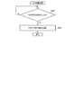
- cpu
- control
- fpga
- Prior art date
- Legal status (The legal status is an assumption and is not a legal conclusion. Google has not performed a legal analysis and makes no representation as to the accuracy of the status listed.)
- Ceased
Links
Images



Classifications
-
- A—HUMAN NECESSITIES
- A61—MEDICAL OR VETERINARY SCIENCE; HYGIENE
- A61B—DIAGNOSIS; SURGERY; IDENTIFICATION
- A61B1/00—Instruments for performing medical examinations of the interior of cavities or tubes of the body by visual or photographical inspection, e.g. endoscopes; Illuminating arrangements therefor
- A61B1/00147—Holding or positioning arrangements
- A61B1/0016—Holding or positioning arrangements using motor drive units
-
- A—HUMAN NECESSITIES
- A61—MEDICAL OR VETERINARY SCIENCE; HYGIENE
- A61B—DIAGNOSIS; SURGERY; IDENTIFICATION
- A61B1/00—Instruments for performing medical examinations of the interior of cavities or tubes of the body by visual or photographical inspection, e.g. endoscopes; Illuminating arrangements therefor
- A61B1/00002—Operational features of endoscopes
- A61B1/00004—Operational features of endoscopes characterised by electronic signal processing
- A61B1/00006—Operational features of endoscopes characterised by electronic signal processing of control signals
-
- A—HUMAN NECESSITIES
- A61—MEDICAL OR VETERINARY SCIENCE; HYGIENE
- A61B—DIAGNOSIS; SURGERY; IDENTIFICATION
- A61B1/00—Instruments for performing medical examinations of the interior of cavities or tubes of the body by visual or photographical inspection, e.g. endoscopes; Illuminating arrangements therefor
- A61B1/00002—Operational features of endoscopes
- A61B1/00039—Operational features of endoscopes provided with input arrangements for the user
- A61B1/00042—Operational features of endoscopes provided with input arrangements for the user for mechanical operation
-
- A—HUMAN NECESSITIES
- A61—MEDICAL OR VETERINARY SCIENCE; HYGIENE
- A61B—DIAGNOSIS; SURGERY; IDENTIFICATION
- A61B1/00—Instruments for performing medical examinations of the interior of cavities or tubes of the body by visual or photographical inspection, e.g. endoscopes; Illuminating arrangements therefor
- A61B1/00002—Operational features of endoscopes
- A61B1/00057—Operational features of endoscopes provided with means for testing or calibration
-
- A—HUMAN NECESSITIES
- A61—MEDICAL OR VETERINARY SCIENCE; HYGIENE
- A61B—DIAGNOSIS; SURGERY; IDENTIFICATION
- A61B1/00—Instruments for performing medical examinations of the interior of cavities or tubes of the body by visual or photographical inspection, e.g. endoscopes; Illuminating arrangements therefor
- A61B1/00131—Accessories for endoscopes
- A61B1/00133—Drive units for endoscopic tools inserted through or with the endoscope
-
- A—HUMAN NECESSITIES
- A61—MEDICAL OR VETERINARY SCIENCE; HYGIENE
- A61B—DIAGNOSIS; SURGERY; IDENTIFICATION
- A61B1/00—Instruments for performing medical examinations of the interior of cavities or tubes of the body by visual or photographical inspection, e.g. endoscopes; Illuminating arrangements therefor
- A61B1/00147—Holding or positioning arrangements
- A61B1/00148—Holding or positioning arrangements using anchoring means
-
- G—PHYSICS
- G02—OPTICS
- G02B—OPTICAL ELEMENTS, SYSTEMS OR APPARATUS
- G02B23/00—Telescopes, e.g. binoculars; Periscopes; Instruments for viewing the inside of hollow bodies; Viewfinders; Optical aiming or sighting devices
- G02B23/24—Instruments or systems for viewing the inside of hollow bodies, e.g. fibrescopes
- G02B23/2407—Optical details
- G02B23/2423—Optical details of the distal end
- G02B23/243—Objectives for endoscopes
-
- G—PHYSICS
- G02—OPTICS
- G02B—OPTICAL ELEMENTS, SYSTEMS OR APPARATUS
- G02B23/00—Telescopes, e.g. binoculars; Periscopes; Instruments for viewing the inside of hollow bodies; Viewfinders; Optical aiming or sighting devices
- G02B23/24—Instruments or systems for viewing the inside of hollow bodies, e.g. fibrescopes
- G02B23/2407—Optical details
- G02B23/2461—Illumination
- G02B23/2469—Illumination using optical fibres
-
- G—PHYSICS
- G02—OPTICS
- G02B—OPTICAL ELEMENTS, SYSTEMS OR APPARATUS
- G02B23/00—Telescopes, e.g. binoculars; Periscopes; Instruments for viewing the inside of hollow bodies; Viewfinders; Optical aiming or sighting devices
- G02B23/24—Instruments or systems for viewing the inside of hollow bodies, e.g. fibrescopes
- G02B23/2476—Non-optical details, e.g. housings, mountings, supports
-
- G—PHYSICS
- G02—OPTICS
- G02B—OPTICAL ELEMENTS, SYSTEMS OR APPARATUS
- G02B23/00—Telescopes, e.g. binoculars; Periscopes; Instruments for viewing the inside of hollow bodies; Viewfinders; Optical aiming or sighting devices
- G02B23/24—Instruments or systems for viewing the inside of hollow bodies, e.g. fibrescopes
- G02B23/2476—Non-optical details, e.g. housings, mountings, supports
- G02B23/2484—Arrangements in relation to a camera or imaging device
-
- G—PHYSICS
- G02—OPTICS
- G02B—OPTICAL ELEMENTS, SYSTEMS OR APPARATUS
- G02B23/00—Telescopes, e.g. binoculars; Periscopes; Instruments for viewing the inside of hollow bodies; Viewfinders; Optical aiming or sighting devices
- G02B23/24—Instruments or systems for viewing the inside of hollow bodies, e.g. fibrescopes
- G02B23/26—Instruments or systems for viewing the inside of hollow bodies, e.g. fibrescopes using light guides
Definitions
- the present invention relates to a control device that controls the operation of a self-propelled mechanism of an endoscope, and a self-propelled endoscope system.
- an endoscope apparatus called a self-propelled type or the like is known.
- the endoscope apparatus described in International Publication WO2016 / 159127 is a rotary self-propelled endoscope apparatus.
- a rotation self-propelled endoscope apparatus for example, a rotary cylinder called a power spiral tube or the like in which a spiral fin is formed on the outer peripheral surface of the insertion portion is provided.
- fins formed on the rotary cylinder contact the wall of the lumen to generate a propulsive force.
- the insertion portion is self-propelled in the insertion direction or the removal direction.
- WO 2016/159127 discloses that the load acting on the rotary cylinder is detected, and the rotation of the rotary cylinder is temporarily stopped when the load becomes larger than a predetermined value. .
- the present invention is a control device for controlling the operation of a self-propelled mechanism of an endoscope in which the rotation of a motor for operating the self-propelled mechanism is reliably stopped when the load acting on the self-propelled mechanism increases. It is an object of the present invention to provide an endoscope system.
- the control device controls the operation of the self-propelled mechanism of an endoscope having a self-propelled mechanism that advances or retracts the insertion portion using a motor as a power source,
- a drive circuit that outputs a motor current for driving a motor, a motor current detection circuit that acquires a value related to the magnitude of the motor current as a detected value, and a storage circuit that stores a limit value related to the detected value
- the drive circuit is controlled so as to stop the motor when the software compares the detected value with the limit value and determines that the detected value exceeds the value related to the limit value, and the hardware
- the drive circuit is controlled to stop the motor when it is determined that the detected value exceeds the value related to the limit value by comparing the detected value and the limit value.
- a control circuit that outputs a motor current for driving a motor, a motor current detection circuit that acquires a value related to the magnitude of the motor current as a detected value, and a storage circuit that stores a limit value related to the detected value
- a self-propelled endoscope system includes the control device described above and the endoscope having the self-propelled mechanism.
- a control device for controlling the operation of the self-propelled mechanism of the endoscope in which the rotation of the motor for operating the self-propelled mechanism is reliably stopped It is possible to provide a self-propelled endoscope system.
- FIG. 1 is a diagram showing an outline of an endoscope system configuration example according to an embodiment.
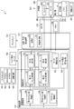
- FIG. 2 is a block diagram showing an outline of a configuration example of an endoscope system according to an embodiment.
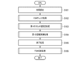
- FIG. 3 is a flowchart showing an example of an outline of main processing performed by the CPU of the control device according to an embodiment.
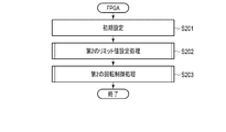
- FIG. 4 is a flowchart showing an example of an outline of main processing performed by the FPGA of the control device according to an embodiment.
- FIG. 5 is a flowchart showing an example of an outline of the FSW check process performed by the CPU of the control device according to one embodiment.
- FIG. 6 is a flowchart showing an example of an outline of a first limit value setting process performed by the CPU of the control device according to one embodiment.
- FIG. 7 is a flowchart showing an example of an outline of a second limit value setting process performed by the FPGA of the control device according to one embodiment.
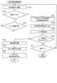
- FIG. 8 is a flowchart showing an example of an outline of a first rotation control process performed by the CPU of the control device according to one embodiment.
- FIG. 9 is a flowchart showing an example of an outline of a second rotation control process performed by the FPGA of the control device according to one embodiment.
- FIG. 10 is a flowchart showing an example of an outline of the FSW disconnection process performed by the CPU of the control device according to one embodiment.
- the present embodiment relates to an endoscope system provided with a self-propelled mechanism that generates a propulsive force for advancing or retracting the insertion portion of the endoscope.
- FIG. 1 is a view schematically showing the configuration of an endoscope system 1 as an example of an insertion device according to an embodiment of the present invention.
- the endoscope system 1 includes an endoscope 200, a light source / image processing device 310, a display 320, a control device 100, a foot switch (FSW) 180, and a torque display unit 190. Equipped with
- the endoscope 200 is a rotary self-propelled endoscope.
- the endoscope 200 has an insertion portion 210.
- the insertion portion 210 has an elongated shape and is configured to be inserted into a living body.
- the endoscope 200 also has a control unit 260 for performing various operations of the endoscope 200.
- the control unit 260 is held by the user.
- the tip side of the insertion portion 210 is referred to as the tip side.
- the side on which the control unit 260 of the insertion portion 210 is provided is referred to as a base end side.
- the direction along the proximal end side from the distal end side of the insertion portion 210 is taken as a longitudinal direction.
- the control unit 260 of the endoscope 200 and the light source / image processing device 310 are connected by a universal cable 290.
- a connector 292 is provided at the end of the universal cable 290, and the connection between the light source / image processing device 310 and the universal cable 290 is made using the connector 292.
- the light source / image processing device 310 and the control device 100 are connected, and the endoscope 200 and the control device 100 are connected via the light source / image processing device 310.
- the insertion portion 210 has a distal end rigid portion 212, a bending portion 214, and a flexible tube portion 216.
- the distal end rigid portion 212 is a distal end portion of the insertion portion 210 and is configured not to bend.
- the bending portion 214 is a portion formed on the proximal end side of the distal end rigid portion 212, and is configured to actively bend in response to the operation of the operation portion 261 provided in the control unit 260.
- the flexible tube portion 216 is a portion formed on the proximal end side of the bending portion 214, and is configured to passively bend by an external force.
- the distal end rigid portion 212 has an imaging element 220 and an illumination lens 221.
- the imaging element 220 generates, for example, an image signal based on a subject image on the distal end side of the insertion unit 210.
- the image signal generated by the imaging element 220 is transmitted to the light source / image processing device 310 via an image signal signal line (not shown) passing through the insertion unit 210 and the universal cable 290.
- the illumination lens 221 diffuses and emits the light guided from the light source / image processing device 310 through an optical fiber (not shown) passing through the insertion portion 210 and the universal cable 290.
- the endoscope system 1 includes a self-propelled mechanism 201. That is, on the flexible tube portion 216 of the insertion portion 210, a rotating portion 230 for transmitting the driving force of the motor 252 as a power source built in the control unit 260 is attached. Further, a power spiral tube 232, which is a rotating cylinder, is attached to the tip end side of the rotating portion 230.
- the power spiral tube 232 is formed in a cylindrical shape, for example, by a flexible material such as rubber or resin, and is mounted rotatably around the longitudinal axis of the flexible tube portion 216.
- a spiral-shaped fin 234 is provided on the outer peripheral surface of the power spiral tube 232 along the longitudinal axis of the power spiral tube 232.
- the power spiral tube 232 may be configured to be removable from the rotating unit 230.
- the power spiral tube 232 is connected to a motor 252 as an actuator provided in the control unit 260.
- the motor 252 is connected to the control device 100 via an actuator current signal signal line (not shown) passing through the control unit 260 and the universal cable 290.
- the motor 252 operates by an operation using the foot switch 180.
- the rotational force of the motor 252 is transmitted to the rotating unit 230.
- the fins 234 provided on the power spiral tube 232 rotate around the longitudinal axis.
- a propulsive force that causes the insertion portion 210 to be self-propelled is generated.
- the propelling force acts on the insertion portion 210 by the fins 234 hand-rolling the wrinkles present on the inner wall of the small intestine and the large intestine.
- the insertion portion 210 is self-propelled by this propulsive force.
- the self-traveling of the insertion unit 210 assists the user in inserting and removing the insertion unit 210.
- the rotation direction of the motor 252 that causes the insertion portion 210 to self-travel to the distal end is the normal rotation direction (insertion direction), and the rotation direction of the motor 252 that causes the insertion portion 210 to self-progress It is in the reverse direction (extraction direction).
- the self-propelled mechanism 201 is configured to temporarily stop the rotation of the motor 252 and temporarily interrupt the insertion of the insertion portion 210 when the torque generated by the motor 252 exceeds a predetermined limit value. .
- Such a temporary stop of the rotation of the motor 252 contributes to preventing damage to the inner wall, avoiding failure of the self-propelled mechanism 201, and the like.
- an encoder 254 is provided in the vicinity of the motor 252.
- the encoder 254 generates a pulse signal (rotational speed signal) according to the rotational speed of the motor 252.
- the rotational speed signal is transmitted to control device 100 via a rotational speed signal line (not shown) passing through universal cable 290.
- the rotation of the motor 252 is controlled using the rotational speed as a feedback value.
- the display 320 has a general display element such as a liquid crystal display.
- the display 320 displays an endoscopic image based on an image signal obtained by the imaging device 220, for example.
- the display 320 may display the state of the self-propelled mechanism 201.
- the information displayed on the display 320 may include an error display for notifying the user of the abnormality of the self-propelled mechanism 201.
- Foot switch 180 includes a forward (FORWARD, F) pedal 182 and a backward (BACKWARD, B) pedal 184.
- the F pedal 182 is a pedal that is stepped on when the user wants to rotate the motor 252 forward.
- the B pedal 184 is a pedal that is stepped on when the user wants to reverse the motor 252.
- Each of the F pedal 182 and the B pedal 184 is configured such that the amount of depression is detected as an input state.
- the foot switch 180 also includes a diagnostic circuit 186 that diagnoses the state of the foot switch 180.
- the diagnosis circuit 186 operates with the power supplied from the control device 100 and transmits the diagnosis result to the control device 100.
- the torque display unit 190 is a display device configured using a display element such as an LED, for example, and displays a value related to the torque generated by the motor 252.
- the torque display unit 190 has a display area in which, for example, the magnitude of the torque on the forward rotation side and the magnitude of the torque on the reverse rotation side are indicated by the number of lighted display elements.
- the torque display unit 190 may be configured to perform an error display for notifying the user of the abnormality of the self-propelled mechanism 201.
- FIG. 2 is a block diagram showing an outline of a configuration example of the endoscope system 1.
- the light source / image processing apparatus 310 includes a light source unit 312 and an image processing unit 314.
- the light source unit 312 includes, for example, a white LED or a xenon lamp, and inputs light to an optical fiber (not shown) in the universal cable 290. This light is guided to the tip of the insertion portion 210 and emitted from the illumination lens 221.
- the image processing unit 314 acquires an image signal from the imaging element 220 via the insertion unit 210 and the universal cable 290.
- the image processing unit 314 performs image processing on the acquired image signal.
- the image processing unit 314 transmits the processed image signal to the display 320, and causes the display 320 to display an endoscopic image.
- Control device 100 controls the operation of the self-propelled mechanism 201.
- Control device 100 includes a control circuit 110, a storage circuit 140, a motor drive circuit 152, and a motor current detection circuit 154.
- the control circuit 110 controls the operation of the self-propelled mechanism 201, the display of the torque display unit 190, and the like.
- the control circuit 110 includes a central processing unit (CPU) 120 and a field programmable gate array (FPGA) 130.
- the CPU 120 functions as a software control unit that performs various processes based on software.
- the processing content of the FPGA 130 is set by hardware, and functions as a hardware control unit that performs various types of processing by the hardware.
- the CPU 120 and the FPGA 130 exchange data.
- a circuit programmed by hardware such as an application specific integrated circuit (ASIC) may be used.
- ASIC application specific integrated circuit
- the motor drive circuit 152 includes, for example, a driver amplifier circuit.
- the motor drive circuit 152 outputs a motor current based on the command value received from the control circuit 110 to drive the motor 252.
- the motor 252 rotates in the forward direction at a rotational speed corresponding to the degree of depression of the F pedal 182.
- the motor 252 reverses at a rotational speed corresponding to the degree of depression of the B pedal 184.
- the motor current detection circuit 154 detects a value related to the current output from the motor drive circuit 152 to the motor 252.
- the motor current detection circuit 154 transmits a signal related to the detected output current to the control circuit 110.
- the storage circuit 140 is a recording medium, such as a FLASH memory, whose contents are stored even after the power is turned off.
- the storage circuit 140 includes, for example, a program storage unit 142 in which a program used by the CPU 120 of the control circuit 110 is recorded.
- the storage circuit 140 also includes a first limit value storage unit 144 for recording a first limit value described later and a second limit value storage unit 146 for recording a second limit value.
- the memory circuit 140 is not limited to a semiconductor memory, and may be a medium using magnetism or light. That is, various recording media can bear the function of the storage circuit 140 as a recording unit.
- the CPU 120 of the control circuit 110 implements functions as the first control unit 122 and the first limit determination unit 124.
- the FPGA 130 implements functions as the second control unit 132 and the second limit determination unit 134.
- the first control unit 122 detects that the user depresses the F pedal 182 or the B pedal 184 and detects the amount of depression. In addition, the first control unit 122 takes in the rotational speed signal input from the encoder 254 every predetermined sampling period. The first control unit 122 creates a command value related to the motor current output from the motor drive circuit 152. The command value is calculated as a value that causes the motor 252 to rotate at a rotational speed corresponding to the amount of depression of the F pedal 182 and the B pedal 184, using the rotational speed signal as a feedback signal. That is, the first control unit 122 calculates the command value based on the difference between the current motor speed and the target motor speed. The control signal including the command value is output to the motor drive circuit 152 via the second control unit 132 of the FPGA 130.
- the first limit determination unit 124 determines whether the torque of the motor 252 exceeds a first limit value, and stops the rotation of the motor 252 when it exceeds.
- the torque of the motor 252 is expressed based on the motor current supplied to the motor 252. Therefore, the first limit value is a value related to the motor current.
- the first limit determination unit 124 reads the first limit value from the first limit value storage unit 144 of the storage circuit 140.
- the first limit determination unit 124 acquires, from the motor current detection circuit 154, a signal related to the magnitude of the motor current output from the motor drive circuit 152.
- the first limit determination unit 124 determines whether the motor current has exceeded a first limit value.
- the first limit determination unit 124 determines that the torque limit is to be applied.
- the torque limit is to stop the output of the motor current from the motor drive circuit 152 to the motor 252.
- the first limit determination unit 124 transmits that effect to the first control unit 122.
- the first control unit 122 stops the motor 252. That is, the first control unit 122 stops the output of the control signal to the motor drive circuit 152.
- the first control unit 122 acquires information related to the magnitude of the motor current detected by the motor current detection circuit 154 via the first limit determination unit 124.
- the first control unit 122 causes the torque display unit 190 to display a value related to the torque generated by the motor 252 based on the magnitude of the motor current.
- the second control unit 132 of the FPGA 130 transmits the control signal output from the first control unit 122 to the motor drive circuit 152, and operates the motor drive circuit 152 based on the control signal. At this time, the second control unit 132 monitors the presence or absence of depression of the F pedal 182 and the B pedal 184 of the foot switch 180. When the second control unit 132 detects that a command to rotate the motor 252 is being issued from the first control unit 122 despite that the foot switch is not depressed, the second control unit 132 causes the motor to be transmitted from the second control unit 132. The control signal to drive circuit 152 is cut off to stop the operation of motor 252.
- the second limit determination unit 134 determines whether or not the torque of the motor 252 exceeds a second limit value, and stops the rotation of the motor 252 when it exceeds. Since the torque of the motor 252 is expressed based on the motor current supplied to the motor 252, the second limit value is also a value related to the motor current.
- the second limit determination unit 134 reads the second limit value from the second limit value storage unit 146 of the storage circuit 140.
- the second limit value may be larger than, for example, the first limit value used by the first limit determination unit 124.
- the second limit determination unit 134 acquires, from the motor current detection circuit 154, a signal related to the magnitude of the motor current output from the motor drive circuit 152.
- the second limit determination unit 134 determines whether the motor current has exceeded a second limit value. When the second limit determination unit 134 determines that the motor current has exceeded the second limit value, it determines that the torque limit is to be applied. When it is determined that the torque limit is to be applied, the second limit determination unit 134 transmits that effect to the second control unit 132. At this time, the second control unit 132 shuts off the control signal from the second control unit 132 to the motor drive circuit 152, and stops the operation of the motor 252.
- the connector 294 of the endoscope 200 is provided with the memory 294.
- the memory 294 stores values relating to the first limit value and the second limit value. Since the limit value may be set differently for each endoscope 200, it is preferable that an appropriate limit value be recorded in the memory 294 for each endoscope 200.
- the control device 100 preferably reads out the limit value stored in the memory 294 to realize the above-described torque limit function. That is, the control circuit 110 reads out the limit value stored in the memory 294, and the first limit value storage unit 144 and the second limit value storage unit 146 of the storage circuit 140 read the first limit value and the second limit value. Store the limit value of.
- FIG. 3 shows an outline of an example of processing performed by the CPU 120 included in the control circuit 110.
- FIG. 4 shows an outline of an example of processing performed by the FPGA 130 included in the control circuit 110.
- the operation of the CPU 120 shown in FIG. 3 is performed according to the program stored in the program storage unit 142 when the power of the endoscope system 1 is turned on.
- the operation of the FPGA 130 shown in FIG. 4 is performed according to the mounted hardware when the endoscope system 1 is powered on.
- the light source / image processing device 310 a process of displaying an endoscopic image based on the image signal obtained by the imaging device 220 on the display 320 is performed.
- step S101 the CPU 120 performs various initial settings relating to the control device 100.
- step S102 the CPU 120 performs an FSW check process to initialize the foot switch (FSW) 180.
- FSW check process it is determined whether the foot switch 180 is normal. The FSW check process will be described in detail later.
- step S103 the CPU 120 performs a first limit value setting process.
- the first limit value setting process setting of a first limit value used by the first limit determination unit 124 is performed.
- the first limit value setting process will be described in detail later. After the above-described various settings, the process proceeds to step S104.
- step S104 the CPU 120 performs a first rotation control process.
- the CPU 120 In the first rotation control process, the CPU 120 generates a control signal such that the motor 252 rotates in response to the input to the foot switch 180. Further, the CPU 120 performs limit determination so that the output torque of the motor 252 does not become equal to or more than the limit value.
- the first rotation control process is a process performed when the endoscope system 1 is used. The first rotation control process will be described in detail later. When the use of the endoscope system 1 is finished and the power is turned off, the process proceeds to step S105.
- step S105 the CPU 120 performs various ending processes. That is, the end process of an unnecessary program etc. is performed and the power supply to an unnecessary part is interrupted
- step S106 the CPU 120 performs FSW disconnection processing. In the FSW disconnection process, the CPU 120 shuts off the power supply to the foot switch 180. Thus, the processing by the CPU 120 ends.
- step S201 the FPGA 130 performs various initial settings related to the operation of the FPGA 130.
- step S202 the FPGA 130 performs a second limit value setting process.
- the second limit value setting process setting of a second limit value used by the second limit determination unit 134 is performed.
- the second limit value setting process will be described in detail later.
- step S203 the FPGA 130 performs a second rotation control process.
- the FPGA 130 outputs the control signal generated by the CPU 120 to the motor drive circuit 152.
- the FPGA 130 performs limit determination so that the output torque of the motor 252 does not become equal to or more than the limit value.
- the second rotation control process is a process performed when the endoscope system 1 is used. The second rotation control process will be described in detail later. When the use of the endoscope system 1 ends and the power is turned off, the processing of the FPGA 130 ends.
- the FSW check process performed by the CPU 120 in step S102 will be described with reference to the flowchart shown in FIG.
- the FSW check process is a process related to the self-diagnosis function performed in the foot switch 180.
- the foot switch 180 itself does not have a power supply, and uses the power supplied from the control device 100 to execute a self-diagnosis. For this reason, in the FSW check process, the timing of supply of power to the foot switch and the timing of acquisition of the self-diagnosis result are adjusted.
- step S301 the CPU 120 determines whether the foot switch 180 is connected to the control device 100. When the foot switch 180 is not connected, the process repeats step S301 and stands by. On the other hand, when the foot switch is connected, the process proceeds to step S302.
- step S302 the CPU 120 starts power supply from the control device 100 to the foot switch 180.
- the diagnostic circuit 186 of the foot switch 180 supplied with power performs self-diagnosis of the inside of the foot switch 180 as to whether the foot switch 180 is normal.
- the diagnosis circuit 186 transmits the diagnosis result to the control circuit 110 in response to a request from the CPU 120.
- step S303 the CPU 120 acquires the result of the internal diagnosis from the foot switch 180.
- the CPU 120 acquires the result of the internal diagnosis at a timing in which the time from when the power supply to the foot switch 180 is started to the time when the result of the self-diagnosis is obtained is taken into consideration.
- step S304 the CPU 120 determines whether the foot switch 180 is normal based on the diagnosis result of the foot switch 180.
- the FSW check process ends, the process returns to the main process of the CPU 120, and proceeds to the first limit value setting process of step S103.
- step S304 When it is determined in step S304 that the foot switch 180 is not normal, the process proceeds to step S305.
- step S305 the CPU 120 performs an error notification process. For example, the CPU 120 causes the display 320 or the torque display unit 190 to display that the foot switch 180 is abnormal. Thereafter, the CPU 120 ends the series of processes. Control device 100 may notify the user of an error by voice.
- the foot switch 180 can accurately perform self-diagnosis, and the CPU 120 can accurately acquire the result. Assuming that the connection of the foot switch 180 is not confirmed as in the FSW check process, for example, the CPU 120 performs self-diagnosis from the foot switch 180 which is late to be connected to the control device 100 and is not subjected to self-diagnosis. There is a possibility of trying to get the result. In such a case, although there is no abnormality in the foot switch 180, the CPU 120 may determine that there is an abnormality in the foot switch 180, and the process may end. According to the FSW check process, the CPU 120 can prevent such a malfunction.
- step S401 the CPU 120 reads the limit value used by the CPU 120 from the memory 294 provided in the connector 292 of the endoscope 200, and stores the limit value in the first limit value storage unit 144 of the storage circuit 140.
- step S402 the CPU 120 outputs an instruction to read the limit value from the memory 294 to the FPGA 130.
- the FPGA 130 reads the limit value used by the FPGA 130 from the memory 294.
- step S403 the CPU 120 determines whether or not the information indicating that the reading of the limit value is completed is received from the FPGA 130.
- the CPU 120 waits until it receives information from the FPGA 130 that reading of the limit value is completed.
- the process proceeds to step S404.
- step S404 the CPU 120 transmits the limit value read by the CPU 120 to the FPGA 130.
- the FPGA 130 which has received the limit value transmitted from the CPU 120 compares the received limit value with the read limit value and transmits the comparison result to the CPU 120, as described later.
- step S405 the CPU 120 receives the comparison result of the limit value from the FPGA 130.
- step S406 the CPU 120 determines whether or not the limit value read by the CPU 120 and the limit value read by the FPGA 130 correspond to each other, for example, within a predetermined range, in the comparison result. . If it is determined that the two limit values correspond to each other, the first limit value setting process ends, the process returns to the main process of the CPU 120, and proceeds to the first rotation control process of step S104. If it is determined that the two limit values do not correspond to each other, the process proceeds to step S407.
- step S407 the CPU 120 gives an error notification. That is, the control device 100 notifies the user that the occurrence of an error has been detected.
- various methods such as display on the torque display unit 190 or the display 320 and output of sound may be used. Thereafter, the CPU 120 ends the series of processes.
- step S501 the FPGA 130 determines whether an instruction to read a limit value has been received.
- the instruction for reading the limit value is the instruction output in step S402 of the first limit value setting process by the CPU 120.
- the FPGA 130 waits for an instruction to read the limit value.
- the process proceeds to step S502.
- step S 502 the FPGA 130 reads the limit value from the memory 294 of the endoscope 200.
- the FPGA 130 stores the read limit value in the second limit value storage unit 146.
- step S503 the FPGA 130 sends the CPU 120 a message indicating that the reading of the limit value has been completed.
- the CPU 120 transmits the limit value read by the CPU in step S404 to the FPGA 130.
- step S504 the FPGA 130 receives the limit value transmitted from the CPU 120.
- step S505 the FPGA 130 compares the limit value read by the FPGA 130 with the limit value read by the CPU 120 from the CPU 120, and determines whether or not they correspond.
- step S506 the FPGA 130 transmits the comparison result of the limit value to the CPU 120. The comparison result is received by the CPU 120 in step S405.
- step S507 the FPGA 130 determines whether the comparison result of the limit value read by the FPGA 130 and the limit value read by the CPU 120 corresponds to each other.
- the comparison result corresponds, the second limit value setting process ends, the process returns to the main process of the FPGA 130, and proceeds to the second rotation control process of step S203.
- step S507 If it is determined in step S507 that the comparison result does not correspond, the process proceeds to step S508.
- step S ⁇ b> 508 the FPGA 130 stops receiving a request for operating the motor 252 from the CPU 120.
- the CPU 120 gives an error notification as described above, and terminates the series of processing. Therefore, if the control circuit 110 is operating normally, the control signal for operating the motor 252 is not transmitted from the CPU 120 to the FPGA 130.
- a control signal for operating the motor 252 may be transmitted from the CPU 120 to the FPGA 130, for example, due to an operation abnormality of the CPU 120.
- the FPGA 130 stops receiving a request for operating the motor 252 from the CPU 120.
- the control signal for rotating the motor 252 from the FPGA 130 to the motor drive circuit 152 is not output.
- the limit value recorded in the memory 294 of the endoscope 200 is stored in the first limit value storage unit 144 and the second limit value storage unit 146.
- the determination as to whether the torque has exceeded the limit value is made by both the CPU 120 and the FPGA 130.
- the control device 100 is configured to make the determination that the torque of the CPU 120 exceeds the limit value earlier than that of the FPGA 130. That is, the conditions under which the CPU 120 causes the software to stop the motor 252 are conditions under which the FPGA 130 is satisfied prior to the conditions under which the hardware causes the motor 252 to stop. Therefore, for example, the first limit value stored in the first limit value storage unit 144 and used by the CPU 120 is based on the second limit value stored in the second limit value storage unit 146 and used by the FPGA 130. It may be a small value.
- the first limit value stored in the first limit value storage unit 144 and used by the CPU 120 is the same as the second limit value stored in the second limit value storage unit 146 and used by the FPGA 130.
- the determination performed by the CPU 120 and the determination performed by the FPGA 130 may be appropriately adjusted.
- the comparison performed in step S505 is appropriately adjusted according to these circumstances.
- the first rotation control process performed by the CPU 120 in step S104 will be described with reference to the flowchart shown in FIG.
- the first rotation control process is an operation when an essential function of the self-propelled mechanism 201 is used.
- step S601 the CPU 120 acquires information related to the depression of the foot switch 180 depressed by the user.
- step S602 the CPU 120 determines whether the foot switch 180 is depressed based on the acquired information. If it is determined that the foot switch 180 is not depressed, the process proceeds to step S603.
- step S603 the CPU 120 stops the rotation of the motor 252.
- the CPU 120 stops the output of the control signal output to the motor drive circuit 152 via the FPGA 130.
- step S 604 the CPU 120 obtains, from the motor current detection circuit 154, the value of the motor current output from the motor drive circuit 152 to the motor 252.
- step S605 the CPU 120 determines whether the motor current is equal to or more than a predetermined value.
- the predetermined value used here may be the first limit value or another value. If the motor current is less than the predetermined value, the process proceeds to step S606.
- step S606 the CPU 120 acquires information related to the rotation of the motor 252 measured using the encoder 254, and determines whether the motor is rotating. If the motor is not rotating, the process returns to step S601. When the foot switch 180 is not depressed, the motor current is not output and the motor 252 should not rotate. When the foot switch 180 is not depressed, the motor current is less than the predetermined value and the motor is not rotating, which is normal. When it is normal, the above process is repeated.
- step S605 If it is determined in step S605 that the motor current is greater than or equal to the predetermined value, the process proceeds to step S607.
- step S606 CPU 120 outputs a signal to stop motor 252.
- the FPGA 130 receiving the stop signal shuts off the output of the control signal to the motor drive circuit 152.
- step S ⁇ b> 608 the CPU 120 gives an error notification notifying the user that there is an abnormality in the operation of the system including the self-propelled mechanism 201.
- the first rotation control process is ended. That is, the operation of the self-propelled mechanism 201 is stopped.
- step S602 If it is determined in step S602 that the foot switch 180 is depressed, the process proceeds to step S609.
- step S ⁇ b> 609 CPU 120 outputs a control signal related to an instruction for rotating motor 252 in accordance with the amount of depression of foot switch 180. That is, the CPU 120 sets the control signal output to the motor drive circuit 152 via the FPGA 130 as a signal corresponding to the stepping amount of the foot switch 180. The motor drive circuit 152 that has received this signal outputs, to the motor 252, power corresponding to the amount of depression of the foot switch 180.
- step S610 the CPU 120 obtains, from the motor current detection circuit 154, a value related to the motor current output from the motor drive circuit 152 to the motor 252.
- step S611 CPU 120 causes torque display unit 190 to display the acquired current value as the torque generated by motor 252.
- step S612 CPU 120 determines whether or not the motor current acquired in step S610 is larger than the first limit value stored in first limit value storage unit 144. If it is determined that the difference is not larger than the first limit value, the process proceeds to step S613.
- step S613 the CPU 120 acquires, from the FPGA 130, information indicating whether the system including the self-running mechanism 201 is operating normally.
- step S614 the CPU 120 determines whether the FPGA 130 has detected an abnormality based on the acquired information. If it is determined that an abnormality is detected, the process proceeds to step S607. That is, a signal for stopping the motor 252 is output, an error notification is performed, and the first rotation control process is ended.
- step S614 If it is determined in step S614 that the FPGA 130 has not detected an abnormality, the process proceeds to step S615.
- step S615 CPU 120 determines whether or not the power of self-propelled mechanism 201 is turned off. When the power is not turned off, the process returns to step S601. On the other hand, when the power is turned off, the first rotation control process ends, the process returns to the main process, and proceeds to step S105.
- step S612 If it is determined in step S612 that the motor current is larger than the first limit value, the process proceeds to step S616.
- step S616 CPU 120 outputs a signal to stop motor 252.
- the motor current has exceeded the first limit value, that is, the torque generated by the motor 252 has exceeded the limit value.
- the CPU 120 causes the torque display unit 190 to display that the torque has exceeded the limit value.
- step S618 the CPU 120 waits for the foot switch 180 to be repressed. That is, it waits for the depression of the foot switch 180 being released to be released.
- step S615. That is, the operation related to the rotation of the motor 252 according to the depression of the foot switch 180 is repeated until the power is turned off or until an abnormality is detected.
- the user depresses the foot switch 180 to perform an insertion operation of the insertion portion 210 of the endoscope 200. Since the torque limit function of the CPU 120 does not generate torque higher than necessary, the user can operate with confidence.
- step S 701 the FPGA 130 acquires information related to the depression of the foot switch 180.
- step S702 the FPGA 130 determines whether the foot switch 180 is depressed based on the acquired information. If it is determined that the foot switch 180 is not depressed, the process proceeds to step S703.
- step S703 the FPGA 130 monitors the control signal output from the CPU 120 to the motor drive circuit 152, and determines whether or not the motor control state for rotating the motor 252 is established. If it is determined that the state is not the motor control state, the process returns to step S701 because the state is normal.
- step S704 determines whether the motor control state is established. If it is determined in step S703 that the motor control state is established, the process proceeds to step S704. The process proceeds to step S704 when the motor control state in which the motor 252 is rotated despite the fact that the foot switch 180 is not depressed is in the abnormal state.
- step S704 the FPGA 130 cuts off the control signal output to the motor drive circuit 152.
- step S 705 the FPGA 130 notifies the CPU 120 that an abnormality has occurred.
- step S706 the FPGA 130 stops receiving a request for operating the motor 252 from the CPU 120. That is, thereafter, the output of the control signal to the motor drive circuit 152 for rotating the motor 252 is stopped. Thereafter, the second rotation control process ends.
- step S702 If it is determined in step S702 that the foot switch 180 is depressed, the process proceeds to step S707.
- step S 707 the FPGA 130 receives the control signal related to the command to rotate the motor 252 output from the CPU 120.
- step S 708 the FPGA 130 outputs the received control signal for rotating the motor 252 to the motor drive circuit 152.
- step S 709 the FPGA 130 obtains, from the motor current detection circuit 154, the value of the motor current output from the motor drive circuit 152 to the motor 252.
- step S710 the FPGA 130 determines whether the motor current is larger than the second limit value. If the motor current is larger than the second limit value, the process proceeds to step S704. If the system is normal, the CPU 120 should first determine that the torque has exceeded the first limit value, and the motor should be stopped. The process proceeds to step S704 when the FPGA 130 determines that the torque has exceeded the second limit value without stopping the motor. That is, this is a case where an abnormality occurs in any part of the system.
- the FPGA 130 cuts off the control signal to the motor drive circuit 152 in step S704, transmits the occurrence of abnormality to the CPU 120 in step S705, stops accepting the operation request from the CPU 120 in step S706, and performs the second rotation control. End the process.
- step S710 If it is determined in step S710 that the motor current is not larger than the second limit value, the process proceeds to step S711.
- step S711 the FPGA 130 determines whether the power of the control device 100 is turned off. When the power is not turned off, the process returns to step S701. On the other hand, when the power is turned off, the second rotation control process ends. As described above, the FPGA 130 monitors the operation of the self-running mechanism in a system different from the CPU 120, and stops the operation when an abnormality is detected.
- step S801 the CPU 120 determines whether the communication between the foot switch 180 and the control device 100 has been disconnected. The process waits until disconnection of the foot switch 180 is detected. If disconnection of the foot switch 180 is detected, the process proceeds to step S802. In step S802, the CPU 120 cuts off the power supply to the foot switch 180. Thus, the control device according to the present embodiment shuts off the power supply to the foot switch 180 when the connection of the foot switch 180 is disconnected.
- the control device 100 even if the torque limit does not work properly in the CPU 120, the torque limit can reliably operate in the FPGA 130.
- software may perform an abnormal operation. Since the FPGA 130 independently performs processing by hardware without the influence of software, the control device 100 according to the present embodiment is more reliable in the operation related to the torque limit than when only the CPU 120 performs the torque limit function. Sex is high.
- the FPGA 130 monitors the relationship between the amount of depression of the foot switch 180 and the control signal output from the CPU 120, and supplies power to the motor 252 when a mismatch is detected regarding these relationships. Stop. Such a function of the FPGA 130 can prevent the motor 252 from rotating due to a malfunction in the operation of the CPU 120 even though the user does not step on the foot switch 180, for example.
- the motor current and the rotation of the motor 252 are monitored even when the foot switch 180 is not depressed.
- the FPGA 130 stops the power supply to the motor 252.
- Such a function of the FPGA 130 can prevent the motor 252 from rotating due to a malfunction in the operation of the CPU 120 even though the user does not step on the foot switch 180, for example.
- the configuration of the self-propelled mechanism 201 shown in the present embodiment is an example.
- the self-propelled mechanism may have any configuration.
- a belt that rotates in the longitudinal direction of the insertion portion 210 may be provided on the outer periphery of the insertion portion 210.
- the torque limit function is carried by two systems of the CPU 120 and the FPGA 130 has been described as an example, but the present invention is not limited to this.
- the torque limit function may be carried by each of the two CPUs.
- Some of the processes described in the above embodiments may be omitted, replaced, or other processes may be added.
- the FSW check process of step S102 or the FSW disconnection process of step S106 may be omitted.
- the limit value is set in advance in the storage circuit 140
- the first limit value setting process of step S103 and the second limit value setting process of step S202 may be omitted.
- the order of processing described in the embodiment may be changed as appropriate. Further, whether each process is performed by the CPU 120 or the FPGA 130 may be changed as appropriate. However, it is preferable to take into consideration that the processing of the FPGA 130 not based on software may have higher certainty.
Landscapes
- Health & Medical Sciences (AREA)
- Life Sciences & Earth Sciences (AREA)
- Physics & Mathematics (AREA)
- Surgery (AREA)
- Engineering & Computer Science (AREA)
- Optics & Photonics (AREA)
- Biomedical Technology (AREA)
- Veterinary Medicine (AREA)
- Pathology (AREA)
- Radiology & Medical Imaging (AREA)
- Biophysics (AREA)
- Nuclear Medicine, Radiotherapy & Molecular Imaging (AREA)
- Public Health (AREA)
- Heart & Thoracic Surgery (AREA)
- Medical Informatics (AREA)
- Molecular Biology (AREA)
- Animal Behavior & Ethology (AREA)
- General Health & Medical Sciences (AREA)
- Astronomy & Astrophysics (AREA)
- General Physics & Mathematics (AREA)
- Signal Processing (AREA)
- Mechanical Engineering (AREA)
- Multimedia (AREA)
- Endoscopes (AREA)
- Instruments For Viewing The Inside Of Hollow Bodies (AREA)
Abstract
制御装置は、モータを動力源として挿入部を前進又は後退させる自走機構を有する内視鏡の前記自走機構の動作を制御する制御装置である。制御装置は、モータを駆動するためのモータ電流を出力するモータ駆動回路と、モータ電流の大きさに係る値を検出値として取得するモータ電流検出回路と、検出値に係るリミット値を格納する記憶回路と、ソフトウェア及びハードウェアのそれぞれにより、検出値とリミット値とを比較して検出値がリミット値に係る値を超えたと判断したときにモータを停止させるように制御する制御回路とを備える。
Description
本発明は、内視鏡の自走機構の動作を制御する制御装置、及び自走式内視鏡システムに関する。
一般に、内視鏡等は、その挿入部が例えば管腔内に挿入される。管腔内に挿入される内視鏡のうち、自走式等と呼ばれる内視鏡装置が知られている。
例えば国際公開第2016/159127号に記載の内視鏡装置は、回転自走式の内視鏡装置である。このような回転自走式の内視鏡装置では、例えば挿入部の外周面に螺旋形状のフィンが形成されたパワースパイラルチューブ等と呼ばれる回転筒体が設けられている。回転筒体が回転すると、回転筒体に形成されたフィンが管腔内壁に接触して推進力を発生させる。この推進力により、挿入部は、挿入方向又は抜去方向に自走する。国際公開第2016/159127号には、回転筒体に作用する負荷を検知して、負荷が所定値よりも大きくなったとき回転筒体の回転が一時的に停止させられることが開示されている。
本発明は、自走機構に作用する負荷が大きくなったときに、自走機構を動作させるモータの回転が確実に止められる内視鏡の自走機構の動作を制御する制御装置、及び自走式内視鏡システムを提供することを目的とする。
本発明の一態様によれば、制御装置は、モータを動力源として挿入部を前進又は後退させる自走機構を有する内視鏡の前記自走機構の動作を制御する制御装置であって、前記モータを駆動するためのモータ電流を出力する駆動回路と、前記モータ電流の大きさに係る値を検出値として取得するモータ電流検出回路と、前記検出値に係るリミット値を格納する記憶回路と、ソフトウェアにより、前記検出値と前記リミット値とを比較して前記検出値が前記リミット値に係る値を超えたと判断したときに前記モータを停止させるように前記駆動回路を制御し、ハードウェアにより、前記検出値と前記リミット値とを比較して前記検出値が前記リミット値に係る値を超えたと判断したときに前記モータを停止させるように前記駆動回路を制御する制御回路とを備える。
本発明の一態様によれば、自走式内視鏡システムは、上述の制御装置と、前記自走機構を有する前記内視鏡とを備える。
本発明によれば、自走機構に作用する負荷が大きくなったときに、自走機構を動作させるモータの回転が確実に止められる内視鏡の自走機構の動作を制御する制御装置、及び自走式内視鏡システムを提供できる。
本発明の一実施形態について図面を参照して説明する。本実施形態は、内視鏡の挿入部を前進又は後退させる推進力を発生する自走機構を備えた内視鏡システムに係る。
[内視鏡システムの構成]
図1は、本発明の一実施形態に係る挿入装置の一例としての内視鏡システム1の構成の概略を示す図である。この図に示すように、内視鏡システム1は、内視鏡200と、光源・画像処理装置310と、ディスプレイ320と、制御装置100と、フットスイッチ(FSW)180と、トルク表示ユニット190とを備える。
図1は、本発明の一実施形態に係る挿入装置の一例としての内視鏡システム1の構成の概略を示す図である。この図に示すように、内視鏡システム1は、内視鏡200と、光源・画像処理装置310と、ディスプレイ320と、制御装置100と、フットスイッチ(FSW)180と、トルク表示ユニット190とを備える。
内視鏡200は、回転自走式の内視鏡である。内視鏡200は、挿入部210を有している。挿入部210は、細長形状であり、生体内に挿入されるように構成されている。また内視鏡200は、内視鏡200の各種操作を行うためのコントロールユニット260を有している。コントロールユニット260は、使用者によって保持される。ここでは挿入部210の先端の側を先端側と称する。また挿入部210のコントロールユニット260が設けられている側を基端側と称する。挿入部210の先端側から基端側に沿った方向を長手方向とする。内視鏡200のコントロールユニット260と光源・画像処理装置310とは、ユニバーサルケーブル290によって接続されている。ユニバーサルケーブル290の端部には、コネクタ292が設けられており、光源・画像処理装置310とユニバーサルケーブル290との接続は、コネクタ292を用いて行われる。光源・画像処理装置310と制御装置100とは接続されており、内視鏡200と制御装置100とは、光源・画像処理装置310を介して接続されている。
挿入部210は、先端硬性部212と、湾曲部214と、蛇管部216とを有する。先端硬性部212は、挿入部210の最先端の部分であり、湾曲しないように構成されている。湾曲部214は、先端硬性部212の基端側に形成されている部分であり、コントロールユニット260に設けられた操作部261の操作に応じて能動的に湾曲するように構成されている。蛇管部216は、湾曲部214の基端側に形成されている部分であり、外力によって受動的に湾曲するように構成されている。
先端硬性部212は、撮像素子220と照明レンズ221とを有している。撮像素子220は、例えば挿入部210の先端側の被写体像に基づく画像信号を生成する。撮像素子220で生成された画像信号は、挿入部210及びユニバーサルケーブル290を通る図示しない画像信号用信号線を介して光源・画像処理装置310に伝送される。照明レンズ221は、挿入部210及びユニバーサルケーブル290を通る図示しない光ファイバを介して光源・画像処理装置310から導かれた光を拡散して放射する。
本実施形態に係る内視鏡システム1は、自走機構201を備える。すなわち、挿入部210の蛇管部216には、コントロールユニット260に内蔵された動力源としてのモータ252の駆動力を伝達するための回転部230が取り付けられている。また、回転部230の先端側には、回転筒体であるパワースパイラルチューブ232が取り付けられている。パワースパイラルチューブ232は、例えばゴムや樹脂等の軟性材料により筒形状に形成され、蛇管部216の長手軸周りに回転可能に装着されている。パワースパイラルチューブ232の外周面には、パワースパイラルチューブ232の長手軸に沿って螺旋形状のフィン234が設けられている。なお、パワースパイラルチューブ232は、回転部230から取り外し可能に構成されていてもよい。
また、パワースパイラルチューブ232は、コントロールユニット260に設けられたアクチュエータとしてのモータ252に接続されている。モータ252は、コントロールユニット260及びユニバーサルケーブル290を通る図示しないアクチュエータ電流信号用信号線を介して制御装置100に接続されている。
モータ252は、フットスイッチ180を用いた操作によって動作する。モータ252の回転力は、回転部230に伝達される。その結果、パワースパイラルチューブ232に設けられたフィン234は、長手軸周りに回転する。
フィン234が例えば管腔内壁といった壁部に接した状態で回転すると、挿入部210を自走させるような推進力が発生する。例えば小腸や大腸においては、小腸や大腸の内壁に存在する襞をフィン234が手繰りよせることによって挿入部210に推進力が作用する。この推進力によって挿入部210が自走する。挿入部210が自走することにより、使用者による挿入部210の挿入作業及び抜去作業が補助される。なお、以下の説明においては、挿入部210を先端側に自走させるモータ252の回転方向を正転方向(挿入方向)とし、挿入部210を基端側に自走させるモータ252の回転方向を逆転方向(抜去方向)とする。
本実施形態に係る自走機構201は、モータ252で発生するトルクが所定のリミット値を超えるとき、モータ252の回転が一時停止し、挿入部210の挿入が一時中断するように構成されている。このようなモータ252の回転の一時停止は、管腔内壁を傷つけないようにすること、自走機構201の故障を回避すること等に貢献する。
モータ252近傍には、エンコーダ254が設けられている。エンコーダ254は、モータ252の回転速度に応じたパルス信号(回転速度信号)を生成する。回転速度信号は、ユニバーサルケーブル290を通る図示しない回転速度用信号線を介して制御装置100に伝達される。自走機構201では、回転速度をフィードバック値として、モータ252の回転が制御される。
ディスプレイ320は、例えば液晶ディスプレイといった一般的な表示素子を有する。ディスプレイ320は、例えば撮像素子220で得られた画像信号に基づく内視鏡画像を表示する。ディスプレイ320は、自走機構201の状態について表示してもよい。ディスプレイ320に表示される情報には、自走機構201の異常をユーザに報知するエラー表示が含まれてもよい。
フットスイッチ180は、前進(FORWARD、F)ペダル182と後退(BACKWARD、B)ペダル184とを含む。Fペダル182は、使用者がモータ252を正転させたいときに踏まれるペダルである。Bペダル184は、使用者がモータ252を逆転させたいときに踏まれるペダルである。Fペダル182及びBペダル184は、それぞれ、踏み込み量が入力状態として検出されるように構成されている。また、フットスイッチ180は、フットスイッチ180の状態を診断する診断回路186を備える。診断回路186は、制御装置100から供給された電力で動作して、診断結果を制御装置100へと伝達する。
トルク表示ユニット190は、例えばLED等の表示素子を用いて構成された表示装置であり、モータ252が発生するトルクに係る値を表示する。トルク表示ユニット190は、例えば正転側のトルクの大きさと逆転側のトルクの大きさとを、それぞれの表示素子の点灯数で示すような表示領域を有している。また、トルク表示ユニット190は、自走機構201の異常をユーザに報知するエラー表示を行えるように構成されていてもよい。
図2は、内視鏡システム1の構成例の概略を示すブロック図である。図2に示すように、光源・画像処理装置310は、光源部312と、画像処理部314とを有する。光源部312は、例えば白色LED又はキセノンランプ等を含み、ユニバーサルケーブル290内の図示しない光ファイバに光を入力する。この光は、挿入部210の先端まで導かれ、照明レンズ221から放射される。画像処理部314は、挿入部210及びユニバーサルケーブル290を介して撮像素子220から画像信号を取得する。画像処理部314は、取得した画像信号に対して画像処理を施す。また、画像処理部314は、処理した画像信号をディスプレイ320に伝達し、ディスプレイ320に内視鏡画像を表示させる。
制御装置100は、自走機構201の動作を制御する。制御装置100は、制御回路110と、記憶回路140と、モータ駆動回路152と、モータ電流検出回路154とを備える。
制御回路110は、自走機構201の動作、トルク表示ユニット190の表示等を制御する。制御回路110は、Central Processing Unit(CPU)120と、Field Programmable Gate Array(FPGA)130とを含む。CPU120は、ソフトウェアに基づいて、各種処理を行うソフトウェア制御部として機能する。FPGA130は、その処理内容がハードウェアによって設定されており、当該ハードウェアによって各種処理を行うハードウェア制御部として機能する。CPU120とFPGA130とは、データのやり取りを行う。FPGAに代えてApplication Specific Integrated Circuit(ASIC)等のハードウェアによってプログラムされている回路が用いられてもよい。なお、ここでは、制御回路110は、CPU120とFPGA130とが1つの集積回路として設けられている例を説明するが、CPU120とFPGA130とは、複数の集積回路として設けられてもよい。
モータ駆動回路152は、例えばドライバアンプ回路含む。モータ駆動回路152は、制御回路110から受け取った指令値に基づいて、モータ電流を出力しモータ252を駆動させる。その結果、モータ252は、Fペダル182の踏み込みの強さに応じた回転速度で正転する。また、モータ252は、Bペダル184の踏み込みの強さに応じた回転速度で逆転する。
モータ電流検出回路154は、モータ駆動回路152からモータ252へと出力される電流に係る値を検出する。モータ電流検出回路154は、検出した出力電流に係る信号を制御回路110へと伝達する。
記憶回路140は、電源を切っても内容が保存される記録媒体、例えばFLASHメモリである。記憶回路140は、例えば、制御回路110のCPU120が用いるプログラムが記録されたプログラム格納部142を含む。また、記憶回路140は、後述する第1のリミット値を記録する第1のリミット値格納部144及び第2のリミット値を記録する第2のリミット値格納部146を含む。記憶回路140は、半導体メモリに限らず、磁気又は光等を用いた媒体でもよい。すなわち、各種記録媒体が記録部として記憶回路140の機能を担い得る。
制御回路110のCPU120は、第1の制御部122及び第1のリミット判断部124としての機能を実現する。FPGA130は、第2の制御部132及び第2のリミット判断部134としての機能を実現する。
第1の制御部122は、使用者によってFペダル182又はBペダル184が踏まれたこと、及びその踏み込み量を検出する。また、第1の制御部122は、エンコーダ254から入力される回転速度信号を所定のサンプリング期間毎に取り込む。第1の制御部122は、モータ駆動回路152から出力されるモータ電流に係る指令値を作成する。指令値は、回転速度信号をフィードバック信号として、Fペダル182及びBペダル184の踏み込み量に応じた回転速度でモータ252が回転するような値として算出される。すなわち、第1の制御部122は、現在のモータ速度と目標のモータ速度との差分に基づいて指令値を算出する。指令値を含む制御信号は、FPGA130の第2の制御部132を介して、モータ駆動回路152へと出力される。
第1のリミット判断部124は、モータ252のトルクが第1のリミット値を超えたか否かを判定し、超えているときにはモータ252の回転を停止させる。ここで、モータ252のトルクはモータ252に供給されるモータ電流に基づいて表される。したがって、第1のリミット値は、モータ電流に係る値である。第1のリミット判断部124は、記憶回路140の第1のリミット値格納部144から第1のリミット値を読み出す。第1のリミット判断部124は、モータ電流検出回路154から、モータ駆動回路152から出力されたモータ電流の大きさに係る信号を取得する。第1のリミット判断部124は、モータ電流が第1のリミット値を超えたか否かを判定する。第1のリミット判断部124は、モータ電流が第1のリミット値を超えたと判定したとき、トルクリミットをかけると判断する。ここで、トルクリミットとは、モータ駆動回路152からモータ252へのモータ電流の出力を停止させることである。第1のリミット判断部124は、トルクリミットをかけると判断したとき、その旨を第1の制御部122へと伝達する。このとき、第1の制御部122は、モータ252を停止させる。すなわち、第1の制御部122は、モータ駆動回路152への制御信号の出力を停止する。
第1の制御部122は、第1のリミット判断部124を介して、モータ電流検出回路154で検出されたモータ電流の大きさに係る情報を取得する。第1の制御部122は、モータ電流の大きさに基づいて、トルク表示ユニット190に、モータ252が発生するトルクに係る値を表示させる。
FPGA130の第2の制御部132は、第1の制御部122から出力された制御信号をモータ駆動回路152へと伝達し、モータ駆動回路152を制御信号に基づいて動作させる。この際、第2の制御部132は、フットスイッチ180のFペダル182及びBペダル184の踏み込みの有無を監視する。第2の制御部132は、フットスイッチが踏み込まれていないにも関わらず第1の制御部122からモータ252を回転させる指令がされていることを検出したときには、第2の制御部132からモータ駆動回路152への制御信号を遮断し、モータ252の動作を停止させる。
第2のリミット判断部134は、モータ252のトルクが第2のリミット値を超えたか否かを判定し、超えているときにはモータ252の回転を停止させる。モータ252のトルクはモータ252に供給されるモータ電流に基づいて表されるので、第2のリミット値も、モータ電流に係る値である。第2のリミット判断部134は、記憶回路140の第2のリミット値格納部146から第2のリミット値を読み出す。ここで、第2のリミット値は、例えば第1のリミット判断部124で用いられる第1のリミット値よりも大きくてもよい。第2のリミット判断部134は、モータ電流検出回路154から、モータ駆動回路152から出力されたモータ電流の大きさに係る信号を取得する。第2のリミット判断部134は、モータ電流が第2のリミット値を超えたか否かを判定する。第2のリミット判断部134は、モータ電流が第2のリミット値を超えたと判定したとき、トルクリミットをかけると判断する。第2のリミット判断部134は、トルクリミットをかけると判断したとき、その旨を第2の制御部132へと伝達する。このとき、第2の制御部132は、第2の制御部132からモータ駆動回路152への制御信号を遮断し、モータ252の動作を停止させる。
なお、本実施形態では、例えば内視鏡200のコネクタ292には、メモリ294が設けられている。メモリ294には、第1のリミット値及び第2のリミット値に係る値が記録されている。リミット値は、内視鏡200毎に異なるように設定された方がいいこともあるので、内視鏡200毎に適切なリミット値がメモリ294に記録されていることが好ましい。制御装置100は、メモリ294に記録されたリミット値を読み出して、上述のトルクリミット機能を実現することが好ましい。すなわち、制御回路110は、メモリ294に記録されたリミット値を読み出して、記憶回路140の第1のリミット値格納部144及び第2のリミット値格納部146に、第1のリミット値及び第2のリミット値をそれぞれ格納する。
[内視鏡システムの動作]
内視鏡システム1の動作について説明する。図3は、制御回路110に含まれるCPU120で行われる処理の一例の概要を示す。図4は、制御回路110に含まれるFPGA130で行われる処理の一例の概要を示す。図3に示すCPU120の動作は、内視鏡システム1の電源がオンにされたときに、プログラム格納部142に格納されたプログラムに従って行われる。図4に示すFPGA130の動作は、内視鏡システム1の電源がオンにされたときに、実装されたハードウェアに応じて行われる。これらの動作と並行して、光源・画像処理装置310では、撮像素子220で得られた画像信号に基づく内視鏡画像をディスプレイ320に表示させる処理等が行われる。
内視鏡システム1の動作について説明する。図3は、制御回路110に含まれるCPU120で行われる処理の一例の概要を示す。図4は、制御回路110に含まれるFPGA130で行われる処理の一例の概要を示す。図3に示すCPU120の動作は、内視鏡システム1の電源がオンにされたときに、プログラム格納部142に格納されたプログラムに従って行われる。図4に示すFPGA130の動作は、内視鏡システム1の電源がオンにされたときに、実装されたハードウェアに応じて行われる。これらの動作と並行して、光源・画像処理装置310では、撮像素子220で得られた画像信号に基づく内視鏡画像をディスプレイ320に表示させる処理等が行われる。
〈CPUのメイン処理〉
CPU120で行われる処理の概要について、図3に示すフローチャートを参照して説明する。
CPU120で行われる処理の概要について、図3に示すフローチャートを参照して説明する。
ステップS101において、CPU120は、制御装置100に係る各種初期設定を行う。ステップS102において、CPU120は、フットスイッチ(FSW)180に関する初期設定を行うFSWチェック処理を行う。FSWチェック処理では、フットスイッチ180が正常であるか否かが判断される。FSWチェック処理については後に詳述する。
ステップS103において、CPU120は、第1のリミット値設定処理を行う。第1のリミット値設定処理では、第1のリミット判断部124で用いられる第1のリミット値の設定が行われる。第1のリミット値設定処理については後に詳述する。以上の各種設定の後、処理はステップS104に進む。
ステップS104において、CPU120は、第1の回転制御処理を行う。第1の回転制御処理では、CPU120は、フットスイッチ180への入力に応じてモータ252が回転するような制御信号を作成する。また、CPU120は、モータ252の出力トルクがリミット値以上にならないように、リミット判断を行う。このように、第1の回転制御処理は、内視鏡システム1が使用されているときに行われる処理である。第1の回転制御処理については、後に詳述する。内視鏡システム1の使用が終了し、電源がオフにされたとき、処理はステップS105に進む。
ステップS105において、CPU120は、各種の終了処理を行う。すなわち、不要なプログラム等の終了処理を行い、不要な部分への電力供給は遮断される。ステップS106において、CPU120は、FSW切断処理を行う。FSW切断処理において、CPU120は、フットスイッチ180への電力供給を遮断する。以上で、CPU120による処理は終了する。
〈FPGAのメイン処理〉
FPGA130で行われる処理の概要について、図4に示すフローチャートを参照して説明する。
FPGA130で行われる処理の概要について、図4に示すフローチャートを参照して説明する。
ステップS201において、FPGA130は、FPGA130の動作に関連する各種初期設定を行う。ステップS202において、FPGA130は、第2のリミット値設定処理を行う。第2のリミット値設定処理では、第2のリミット判断部134で用いられる第2のリミット値の設定が行われる。第2のリミット値設定処理については後に詳述する。以上の各種設定の後、処理はステップS203に進む。
ステップS203において、FPGA130は、第2の回転制御処理を行う。第2の回転制御処理では、FPGA130は、CPU120で作成された制御信号をモータ駆動回路152へと出力する。このとき、FPGA130は、モータ252の出力トルクがリミット値以上にならないように、リミット判断を行う。このように、第2の回転制御処理は、内視鏡システム1が使用されているときに行われる処理である。第2の回転制御処理については、後に詳述する。内視鏡システム1の使用が終了し、電源がオフにされたとき、FPGA130の処理は終了する。
〈CPUのFSWチェック処理〉
CPU120によってステップS102において行われるFSWチェック処理について、図5に示すフローチャートを参照して説明する。FSWチェック処理は、フットスイッチ180において行われる自己診断機能に係る処理である。フットスイッチ180は、自らは電源を持たず、制御装置100から供給される電力を用いて自己診断を実行する。このため、FSWチェック処理では、フットスイッチへの電力の供給のタイミングと自己診断結果の取得のタイミングとが調整されている。
CPU120によってステップS102において行われるFSWチェック処理について、図5に示すフローチャートを参照して説明する。FSWチェック処理は、フットスイッチ180において行われる自己診断機能に係る処理である。フットスイッチ180は、自らは電源を持たず、制御装置100から供給される電力を用いて自己診断を実行する。このため、FSWチェック処理では、フットスイッチへの電力の供給のタイミングと自己診断結果の取得のタイミングとが調整されている。
ステップS301において、CPU120は、制御装置100にフットスイッチ180が接続されたか否かを判定する。フットスイッチ180が接続されていないとき、処理はステップS301を繰り返して待機する。一方、フットスイッチが接続されたとき、処理はステップS302に進む。
ステップS302において、CPU120は、制御装置100からフットスイッチ180への電力供給を開始する。電力が供給されたフットスイッチ180の診断回路186は、フットスイッチ180に異常がないかといったフットスイッチ180の内部の自己診断を行う。診断回路186は、CPU120からの要求に応じて診断結果を制御回路110へと伝達する。
ステップS303において、CPU120は、フットスイッチ180から内部診断の結果を取得する。この際、フットスイッチ180への電力供給を開始してから自己診断の結果が得られるまでの時間が考慮されたタイミングで、CPU120は、内部診断の結果を取得する。
ステップS304において、CPU120は、フットスイッチ180の診断結果に基づいて、フットスイッチ180は正常であるか否かを判定する。フットスイッチ180が正常であるとき、FSWチェック処理は終了し、処理はCPU120のメイン処理に戻り、ステップS103の第1のリミット値設定処理に進む。
ステップS304において、フットスイッチ180は正常でないと判定されたとき、処理はステップS305に進む。ステップS305において、CPU120は、エラー報知処理を行う。例えば、CPU120は、ディスプレイ320又はトルク表示ユニット190に、フットスイッチ180に異常がある旨を表示させる。その後、CPU120は、一連の処理を終了させる。制御装置100は、音声でユーザにエラーを報知してもよい。
FSWチェック処理によって、フットスイッチ180は自己診断を正確に行うことができ、CPU120はその結果を正確に取得することができる。仮に、FSWチェック処理のようにフットスイッチ180の接続の確認が行われないとすると、CPU120は、例えば制御装置100に接続されるのが遅くて自己診断が行われていないフットスイッチ180から自己診断結果を取得しようとしてしまう可能性がある。このような場合、フットスイッチ180に異常がないにも関わらず、CPU120は、フットスイッチ180に異常があると判定し、処理を終了する可能性がある。FSWチェック処理によれば、CPU120は、このような誤動作を防止することができる。
〈CPUの第1のリミット値設定処理〉
CPU120によってステップS103において行われる第1のリミット値設定処理について、図6に示すフローチャートを参照して説明する。
CPU120によってステップS103において行われる第1のリミット値設定処理について、図6に示すフローチャートを参照して説明する。
ステップS401において、CPU120は、内視鏡200のコネクタ292に設けられたメモリ294から、CPU120で用いられるリミット値を読み込み、記憶回路140の第1のリミット値格納部144に格納させる。ステップS402において、CPU120は、FPGA130に対して、メモリ294からリミット値を読み込むよう指示を出力する。この指示を受けたFPGA130は、メモリ294からFPGA130で用いられるリミット値を読み込む。
ステップS403において、CPU120は、FPGA130からリミット値の読み込みが完了した旨の情報を受けたか否かを判定する。CPU120は、FPGA130からリミット値の読み込みが完了した旨の情報を受けるまで、待機する。CPU120がFPGA130からリミット値の読み込みが完了した旨の情報を受けたとき、処理はステップS404に進む。
ステップS404において、CPU120は、FPGA130宛に、CPU120が読み込んだリミット値を送信する。CPU120から送信されたリミット値を受信したFPGA130は、後述するように、受信したリミット値と読み込んだリミット値とを比較して比較結果をCPU120宛に送信する。
ステップS405において、CPU120は、FPGA130からリミット値の比較結果を受信する。ステップS406において、CPU120は、比較結果において、CPU120が読み込んだリミット値とFPGA130が読み込んだリミット値とが、例えばそれらの差が所定の範囲である等、対応するものであるか否かを判定する。両リミット値が対応するものであると判定されたとき、第1のリミット値設定処理は終了し、処理はCPU120のメイン処理に戻り、ステップS104の第1の回転制御処理に進む。一方、両リミット値が対応するものでないと判定されたとき、処理はステップS407に進む。
ステップS407において、CPU120は、エラー報知を行う。すなわち、制御装置100においてエラーの発生を検出した旨を、ユーザに向けて通知する。エラー報知には、トルク表示ユニット190又はディスプレイ320への表示、音声の出力など、種々の方法が用いられ得る。その後、CPU120は、一連の処理を終了させる。
〈FPGAの第2のリミット値設定処理〉
第1のリミット値設定処理が行われている間にFPGA130によってステップS202において行われる第2のリミット値設定処理について、図7に示すフローチャートを参照して説明する。
第1のリミット値設定処理が行われている間にFPGA130によってステップS202において行われる第2のリミット値設定処理について、図7に示すフローチャートを参照して説明する。
ステップS501において、FPGA130は、リミット値読み込みの指示を受けたか否かを判定する。ここで、リミット値読み込みの指示は、CPU120による第1のリミット値設定処理のステップS402で出力された指示のことである。FPGA130は、リミット値読み込みの指示があるまで待機する。リミット値読み込みの指示を受けたとき、処理はステップS502に進む。
ステップS502において、FPGA130は、内視鏡200のメモリ294からリミット値を読み込む。FPGA130は、読み込んだリミット値を第2のリミット値格納部146に格納する。ステップS503において、FPGA130は、CPU120宛にリミット値の読み込みが完了した旨を送信する。この信号に応じて、CPU120は、ステップS404においてCPUで読み込んだリミット値をFPGA130宛に送信する。ステップS504において、FPGA130は、CPU120から送信されたリミット値を受信する。
ステップS505において、FPGA130は、FPGA130が読み込んだリミット値と、CPU120から受信したCPU120が読み込んだリミット値とを比較し、対応しているか否かを判定する。ステップS506において、FPGA130は、リミット値の比較結果をCPU120宛に送信する。この比較結果は、ステップS405においてCPU120で受信される。
ステップS507において、FPGA130は、FPGA130が読み込んだリミット値とCPU120が読み込んだリミット値との比較結果が対応しているか否かを判定する。比較結果が対応しているとき、第2のリミット値設定処理は終了し、処理はFPGA130のメイン処理に戻り、ステップS203の第2の回転制御処理に進む。
ステップS507において比較結果が対応していないと判定されたとき、処理はステップS508に進む。ステップS508において、FPGA130は、CPU120からモータ252を動作させる要求の受付を停止する。比較結果が対応していないとき、上述のとおりCPU120はエラー報知を行い一連の処理を終了させる。したがって、制御回路110が正常に動作していれば、CPU120からFPGA130へモータ252を動作させる制御信号が伝達されることはない。しかしながら、例えばCPU120の動作異常のため、CPU120からFPGA130へモータ252を動作させる制御信号が伝達されることもあり得る。本実施形態では、このような場合にも、FPGA130がCPU120からモータ252を動作させる要求の受付を停止する。その結果、比較結果が対応していないとき、FPGA130からモータ駆動回路152へモータ252を回転させるための制御信号が出力されることはない。ステップS508の処理の後、FPGA130は、一連の処理を終了させる。
以上のようにして、内視鏡200のメモリ294に記録されたリミット値は、第1のリミット値格納部144及び第2のリミット値格納部146に格納される。
トルクがリミット値を超えたか否かの判定は、CPU120とFPGA130との両方で行われる。ここで、CPU120の方がFPGA130よりもトルクがリミット値を超えたという判定を先に下すように制御装置100は構成されている。すなわち、CPU120がソフトウェアによりモータ252を停止させる条件は、FPGA130がハードウェアによりモータ252を停止させる条件よりも先に満たされる条件である。このため、例えば、第1のリミット値格納部144に格納されてCPU120で用いられる第1のリミット値は、第2のリミット値格納部146に格納されてFPGA130で用いられる第2のリミット値よりも小さな値としてもよい。また、第1のリミット値格納部144に格納されてCPU120で用いられる第1のリミット値と、第2のリミット値格納部146に格納されてFPGA130で用いられる第2のリミット値とは同一であり、CPU120で行われる判定とFPGA130で行われる判定とが適切に調整されてもよい。ステップS505で行われる比較は、これらの事情に応じて適宜に調整される。
〈CPUの第1の回転制御処理〉
CPU120によってステップS104において行われる第1の回転制御処理について、図8に示すフローチャートを参照して説明する。第1の回転制御処理は、自走機構201が備える本質的な機能が使用される際の動作である。
CPU120によってステップS104において行われる第1の回転制御処理について、図8に示すフローチャートを参照して説明する。第1の回転制御処理は、自走機構201が備える本質的な機能が使用される際の動作である。
ステップS601において、CPU120は、ユーザによって踏み込まれるフットスイッチ180の踏み込みに係る情報を取得する。ステップS602において、CPU120は、取得した情報に基づいて、フットスイッチ180が踏み込まれているか否かを判定する。フットスイッチ180が踏み込まれていないと判定されたとき、処理はステップS603に進む。
ステップS603において、CPU120は、モータ252の回転を停止させる。例えば、CPU120は、FPGA130を介してモータ駆動回路152へと出力される制御信号の出力を停止する。ステップS604において、CPU120は、モータ電流検出回路154から、モータ駆動回路152からモータ252へと出力されるモータ電流の値を取得する。
ステップS605において、CPU120は、モータ電流が所定値以上であるか否かを判定する。ここで用いられる所定値は、第1のリミット値であってもよいし、その他の値であってもよい。モータ電流が所定値未満であるとき、処理はステップS606に進む。ステップS606において、CPU120は、エンコーダ254を用いて測定されたモータ252の回転に係る情報を取得し、モータが回転しているか否かを判定する。モータが回転していないとき、処理はステップS601に戻る。フットスイッチ180が踏まれていないとき、モータ電流は出力されずモータ252が回転しないはずである。フットスイッチ180が踏まれていないとき、モータ電流が所定値未満でありモータが回転していない状態が正常であるので、正常であるとき上述の処理が繰り返される。
ステップS605において、モータ電流が所定値以上であると判定されたとき処理はステップS607に進む。また、ステップS606において、モータが回転していると判定されたとき、処理はステップS607に進む。ステップS607において、CPU120は、モータ252を停止させる信号を出力する。例えば、この停止信号を受信したFPGA130はモータ駆動回路152への制御信号の出力を遮断する。ステップS608において、CPU120は、自走機構201を含むシステムの動作に異常がある旨をユーザに伝えるエラー報知を行う。その後、第1の回転制御処理を終了する。すなわち、自走機構201の動作を停止させる。
ステップS602の判定においてフットスイッチ180が踏み込まれていると判定されたとき、処理はステップS609に進む。ステップS609において、CPU120は、フットスイッチ180の踏み込み量に応じてモータ252を回転させるための指令に係る制御信号を出力する。すなわち、CPU120は、FPGA130を介してモータ駆動回路152へと出力される制御信号を、フットスイッチ180の踏み込み量に応じた信号とする。この信号を受信したモータ駆動回路152は、フットスイッチ180の踏み込み量に応じた電力をモータ252へと出力する。
ステップS610において、CPU120は、モータ電流検出回路154から、モータ駆動回路152からモータ252へと出力されるモータ電流に係る値を取得する。ステップS611において、CPU120は、取得した電流値をトルク表示ユニット190にモータ252で発生しているトルクとして表示させる。
ステップS612において、CPU120は、ステップS610で取得したモータ電流が第1のリミット値格納部144に格納された第1のリミット値よりも大きいか否かを判定する。第1のリミット値よりも大きくないと判定されたとき、処理はステップS613に進む。
ステップS613において、CPU120は、FPGA130から自走機構201を含むシステムが正常に動作しているか否かを表す情報を取得する。ステップS614において、CPU120は、取得した情報に基づいて、FPGA130が異常を検知したか否かを判定する。異常を検知したと判定されたとき、処理はステップS607に進む。すなわち、モータ252を停止させる信号を出力し、エラー報知を行って、第1の回転制御処理を終了させる。
ステップS614において、FPGA130が異常を検知していないと判定されたとき、処理はステップS615に進む。ステップS615において、CPU120は、自走機構201に係る電源がオフにされたか否かを判定する。電源がオフにされていないとき、処理はステップS601に戻る。一方、電源がオフにされたとき、第1の回転制御処理は終了し、処理はメイン処理に戻り、ステップS105に進む。
ステップS612において、モータ電流が第1のリミット値よりも大きいと判定されたとき、処理はステップS616に進む。ステップS616において、CPU120は、モータ252を停止させる信号を出力する。このようにして、モータ252が発生するトルクが第1のリミット値を超えたとき、モータ252の回転を一時停止させる。ステップS617において、CPU120は、モータ電流が第1のリミット値を超えたこと、すなわち、モータ252が発生するトルクがリミット値を超えたことをユーザに報知する。例えば、CPU120は、トルクがリミット値を超えたことをトルク表示ユニット190に表示させる。その後、ステップS618において、CPU120は、フットスイッチ180の踏み直しを待つ。すなわち、踏まれているフットスイッチ180の踏み込みが解放されるのを待つ。フットスイッチ180の踏み込みが解放されたとき、処理はステップS615に進む。すなわち、電源がオフになるまで、又は異常が検知されるまで、フットスイッチ180の踏み込みに応じたモータ252の回転に係る動作が繰り返される。ユーザはフットスイッチ180の踏み込みを操作して、内視鏡200の挿入部210の挿入操作を行う。CPU120のトルクリミット機能によって必要以上に高いトルクが発生しないので、ユーザは安心して操作を行うことができる。
〈FPGAの第2の回転制御処理〉
第1の回転制御処理が行われている間に、FPGA130で行われる第2の回転制御処理について、図9に示すフローチャートを参照して説明する。
第1の回転制御処理が行われている間に、FPGA130で行われる第2の回転制御処理について、図9に示すフローチャートを参照して説明する。
ステップS701において、FPGA130は、フットスイッチ180の踏み込みに係る情報を取得する。ステップS702において、FPGA130は、取得した情報に基づいて、フットスイッチ180が踏み込まれているか否かを判定する。フットスイッチ180が踏み込まれていないと判定されたとき、処理はステップS703に進む。
ステップS703において、FPGA130は、CPU120からモータ駆動回路152へと出力される制御信号を監視し、モータ252を回転させるモータ制御状態であるか否かを判定する。モータ制御状態ではないと判定されたとき、正常な状態であるので、処理はステップS701に戻る。
ステップS703において、モータ制御状態であると判定されたとき、処理はステップS704に進む。処理がステップS704に進むのは、フットスイッチ180が踏まれていないにも関わらずモータ252を回転させるモータ制御状態となっているときであり、異常が発生しているときである。ステップS704において、FPGA130は、モータ駆動回路152へと出力される制御信号を遮断する。ステップS705において、FPGA130は、CPU120宛に異常が発生した旨を伝達する。さらにステップS706において、FPGA130は、CPU120からモータ252を動作させる要求の受付を停止する。すなわち、これ以降、モータ252を回転させるためのモータ駆動回路152への制御信号の出力を停止する。その後、第2の回転制御処理は終了する。
ステップS702においてフットスイッチ180が踏まれていると判定されたとき、処理はステップS707に進む。ステップS707において、FPGA130は、CPU120から出力されたモータ252を回転させる指令に係る制御信号を受信する。ステップS708において、FPGA130は、受信したモータ252を回転させるための制御信号を、モータ駆動回路152へ出力する。
ステップS709において、FPGA130は、モータ電流検出回路154から、モータ駆動回路152からモータ252へと出力されるモータ電流の値を取得する。ステップS710において、FPGA130は、モータ電流が第2のリミット値よりも大きいか否かを判定する。モータ電流が第2のリミット値よりも大きいとき、処理はステップS704に進む。システムが正常であれば先にトルクが第1のリミット値を超えたとCPU120によって判定されてモータが停止させられているはずである。ステップS704に進むのは、それにも関わらず、モータが停止させられずにトルクが第2のリミット値を超えたとFPGA130によって判定される場合である。すなわち、システムの何れかの箇所に異常が発生している場合である。そこで、FPGA130は、ステップS704においてモータ駆動回路152への制御信号を遮断し、ステップS705においてCPU120へ異常発生を伝達し、ステップS706でCPU120からの動作要求の受付を停止し、第2の回転制御処理を終了する。
ステップS710においてモータ電流が第2のリミット値よりも大きくないと判定されたとき、処理はステップS711に進む。ステップS711において、FPGA130は、制御装置100の電源がオフにされたか否かを判定する。電源がオフにされていないとき、処理はステップS701に戻る。一方、電源がオフにされたとき、第2の回転制御処理は終了する。このように、CPU120とは別系統でFPGA130は自走機構の動作を監視して、異常を検知したときにはその動作を停止させる。
〈CPUのFSW切断処理〉
CPU120は、ステップS104の第1の回転制御処理を終了したとき、ステップS105の終了処理を行い、ステップS106のFSW切断処理を行う。FSW切断処理について、図10に示すフローチャートを参照して説明する。ステップS801において、CPU120は、フットスイッチ180と制御装置100との間の通信が切断されたか否かを判定する。フットスイッチ180の切断が検知されるまで処理は待機する。フットスイッチ180の切断が検知されたとき、処理はステップS802に進む。ステップS802において、CPU120は、フットスイッチ180への電力供給を遮断する。このように、本実施形態に係る制御装置は、フットスイッチ180の接続が切断されたとき、フットスイッチ180への電力供給を遮断する。
CPU120は、ステップS104の第1の回転制御処理を終了したとき、ステップS105の終了処理を行い、ステップS106のFSW切断処理を行う。FSW切断処理について、図10に示すフローチャートを参照して説明する。ステップS801において、CPU120は、フットスイッチ180と制御装置100との間の通信が切断されたか否かを判定する。フットスイッチ180の切断が検知されるまで処理は待機する。フットスイッチ180の切断が検知されたとき、処理はステップS802に進む。ステップS802において、CPU120は、フットスイッチ180への電力供給を遮断する。このように、本実施形態に係る制御装置は、フットスイッチ180の接続が切断されたとき、フットスイッチ180への電力供給を遮断する。
本実施形態に係る制御装置100によれば、CPU120でトルクリミットが適切に働かなくても、FPGA130で確実にトルクリミットが動作し得る。CPU120では、ソフトウェアが異常な動作を行う可能性もある。FPGA130は、ソフトウェアの影響を受けずに、独立してハードウェアで処理を行うので、本実施形態に係る制御装置100は、CPU120のみがトルクリミット機能を担う場合よりもトルクリミットに係る動作の確実性が高い。
さらに、本実施形態では、FPGA130は、フットスイッチ180の踏み込み量とCPU120が出力する制御信号との関係を監視しており、これらの関係について不整合が検知されたとき、モータ252への電力供給を停止させる。FPGA130のこのような機能により、例えばユーザがフットスイッチ180を踏んでいないにも関わらず、CPU120の動作の不具合によってモータ252が回転してしまうことを防止できる。
また、本実施形態では、フットスイッチ180が踏み込まれていないときにも、モータ電流及びモータ252の回転が監視される。フットスイッチ180が踏み込まれていないにも関わらずモータ電流が流れたりモータ252が回転したりする場合には、FPGA130はモータ252への電力供給を停止させる。FPGA130のこのような機能により、例えばユーザがフットスイッチ180を踏んでいないにも関わらず、CPU120の動作の不具合によってモータ252が回転してしまうことを防止できる。
[変形例]
本実施形態で示した自走機構201の構成は一例である。自走機構は、どのような構成でもよい。例えば挿入部210の長手方向に回転するベルトが挿入部210の外周に設けられている構成でもよい。
本実施形態で示した自走機構201の構成は一例である。自走機構は、どのような構成でもよい。例えば挿入部210の長手方向に回転するベルトが挿入部210の外周に設けられている構成でもよい。
本実施形態では、トルクリミット機能がCPU120とFPGA130との2系統で担われる場合を例に挙げて説明したが、これに限らない。例えばトルクリミット機能が2系統のCPUの各々によって担われてもよい。
上述の実施形態で説明した処理は、その一部が省略されたり、置換されたり、他の処理が追加されたりしてもよい。例えば、ステップS102のFSWチェック処理又はステップS106のFSW切断処理は省略され得る。リミット値が予め記憶回路140に設定されている場合には、ステップS103の第1のリミット値設定処理及びステップS202の第2のリミット値設定処理は省略され得る。また、実施形態で示した処理の順序は適宜に変更されてもよい。また、各々の処理がCPU120で行われるかFPGA130で行われるかは、適宜に変更されてもよい。ただし、ソフトウェアによらないFPGA130の処理の方が確実性が高いこともあることも考慮されることが好ましい。
Claims (7)
- モータを動力源として挿入部を前進又は後退させる自走機構を有する内視鏡の前記自走機構の動作を制御する制御装置であって、
前記モータを駆動するためのモータ電流を出力する駆動回路と、
前記モータ電流の大きさに係る値を検出値として取得するモータ電流検出回路と、
前記検出値に係るリミット値を格納する記憶回路と、
ソフトウェアにより、前記検出値と前記リミット値とを比較して前記検出値が前記リミット値に係る値を超えたと判断したときに前記モータを停止させるように前記駆動回路を制御し、
ハードウェアにより、前記検出値と前記リミット値とを比較して前記検出値が前記リミット値に係る値を超えたと判断したときに前記モータを停止させるように前記駆動回路を制御する
制御回路と
を備える制御装置。 - 前記ソフトウェアによる前記モータを停止させる条件は、前記ハードウェアによる前記モータを停止させる条件よりも先に満たされる条件である、請求項1に記載の制御装置。
- 前記制御回路は、前記ハードウェアによる前記モータを停止させるという判断がされたとき、前記ソフトウェアによる判断に関わらず、前記モータを停止させるように前記駆動回路を制御する、請求項1に記載の制御装置。
- 前記内視鏡は、ユーザによる前記モータを駆動させるか否かの指示が入力されるスイッチを有しており、
前記制御回路は、
前記ソフトウェアにより、前記スイッチへの入力状態を取得し、前記入力状態に応じて前記駆動回路の出力を制御し、
前記ハードウェアにより、前記スイッチへの入力状態を監視し、前記スイッチに前記モータを駆動させる指示が入力されていないにも関わらず、前記ソフトウェアにより前記モータを動作させるための制御を行っているとき、前記モータを停止させるように前記駆動回路を制御する、
請求項1に記載の制御装置。 - 前記内視鏡は、当該内視鏡の特性としての前記リミット値を記録するメモリを備え、
前記制御回路は、前記メモリに記録された前記リミット値を読み出して、前記記憶回路に前記リミット値を格納する、
請求項1に記載の制御装置。 - 前記制御回路は、前記ソフトウェアにより、前記駆動回路の出力を制御するための制御信号を生成し、
前記制御信号は、前記ハードウェアを介して前記制御回路から前記駆動回路へと出力される、
請求項1に記載の制御装置。 - 請求項1に記載の制御装置と、
前記自走機構を有する前記内視鏡と
を備える自走式内視鏡システム。
Priority Applications (2)
| Application Number | Priority Date | Filing Date | Title |
|---|---|---|---|
| JP2019528948A JP6840851B2 (ja) | 2017-07-12 | 2018-05-10 | 制御装置、自走式内視鏡システム及び制御方法 |
| US16/737,368 US11478123B2 (en) | 2017-07-12 | 2020-01-08 | Control apparatus and self-propelled type endoscope system |
Applications Claiming Priority (2)
| Application Number | Priority Date | Filing Date | Title |
|---|---|---|---|
| JP2017136236 | 2017-07-12 | ||
| JP2017-136236 | 2017-07-12 |
Related Child Applications (1)
| Application Number | Title | Priority Date | Filing Date |
|---|---|---|---|
| US16/737,368 Continuation US11478123B2 (en) | 2017-07-12 | 2020-01-08 | Control apparatus and self-propelled type endoscope system |
Publications (1)
| Publication Number | Publication Date |
|---|---|
| WO2019012791A1 true WO2019012791A1 (ja) | 2019-01-17 |
Family
ID=65001869
Family Applications (1)
| Application Number | Title | Priority Date | Filing Date |
|---|---|---|---|
| PCT/JP2018/018098 Ceased WO2019012791A1 (ja) | 2017-07-12 | 2018-05-10 | 制御装置及び自走式内視鏡システム |
Country Status (3)
| Country | Link |
|---|---|
| US (1) | US11478123B2 (ja) |
| JP (1) | JP6840851B2 (ja) |
| WO (1) | WO2019012791A1 (ja) |
Families Citing this family (8)
| Publication number | Priority date | Publication date | Assignee | Title |
|---|---|---|---|---|
| CN110325098A (zh) | 2016-11-28 | 2019-10-11 | 适内有限责任公司 | 具有可分离一次性轴的内窥镜 |
| JP6498856B1 (ja) * | 2017-07-07 | 2019-04-10 | オリンパス株式会社 | 自走式内視鏡装置及びその制御装置 |
| USD1018844S1 (en) | 2020-01-09 | 2024-03-19 | Adaptivendo Llc | Endoscope handle |
| USD1051380S1 (en) | 2020-11-17 | 2024-11-12 | Adaptivendo Llc | Endoscope handle |
| USD1031035S1 (en) | 2021-04-29 | 2024-06-11 | Adaptivendo Llc | Endoscope handle |
| USD1070082S1 (en) | 2021-04-29 | 2025-04-08 | Adaptivendo Llc | Endoscope handle |
| WO2023275177A1 (en) * | 2021-06-30 | 2023-01-05 | Ambu A/S | Video processing apparatus with noise effect mitigation |
| USD1066659S1 (en) | 2021-09-24 | 2025-03-11 | Adaptivendo Llc | Endoscope handle |
Citations (5)
| Publication number | Priority date | Publication date | Assignee | Title |
|---|---|---|---|---|
| JP2007185390A (ja) * | 2006-01-13 | 2007-07-26 | Olympus Medical Systems Corp | 回転自走式内視鏡システム、プログラム |
| JP2007306993A (ja) * | 2006-05-16 | 2007-11-29 | Olympus Medical Systems Corp | 回転自走式内視鏡システム |
| JP2008093029A (ja) * | 2006-10-06 | 2008-04-24 | Olympus Medical Systems Corp | 回転自走式内視鏡システム |
| US20130158353A1 (en) * | 2011-12-16 | 2013-06-20 | Fujifilm Corporation | Propulsion assembly for endoscope |
| JP2014004268A (ja) * | 2012-06-27 | 2014-01-16 | Fujifilm Corp | 内視鏡挿入補助具、リミット値設定方法 |
Family Cites Families (4)
| Publication number | Priority date | Publication date | Assignee | Title |
|---|---|---|---|---|
| JP4668643B2 (ja) * | 2005-02-23 | 2011-04-13 | オリンパスメディカルシステムズ株式会社 | 内視鏡装置 |
| US20090156897A1 (en) * | 2005-09-30 | 2009-06-18 | Olympus Medical Systems Corp. | Rotating self-propelled endoscope device |
| WO2007080783A1 (ja) * | 2006-01-13 | 2007-07-19 | Olympus Medical Systems Corp. | 回転自走式内視鏡システム、プログラム、回転自走式内視鏡システムの駆動方法 |
| JP6091725B1 (ja) | 2015-04-01 | 2017-03-08 | オリンパス株式会社 | 挿入装置 |
-
2018
- 2018-05-10 WO PCT/JP2018/018098 patent/WO2019012791A1/ja not_active Ceased
- 2018-05-10 JP JP2019528948A patent/JP6840851B2/ja active Active
-
2020
- 2020-01-08 US US16/737,368 patent/US11478123B2/en active Active
Patent Citations (5)
| Publication number | Priority date | Publication date | Assignee | Title |
|---|---|---|---|---|
| JP2007185390A (ja) * | 2006-01-13 | 2007-07-26 | Olympus Medical Systems Corp | 回転自走式内視鏡システム、プログラム |
| JP2007306993A (ja) * | 2006-05-16 | 2007-11-29 | Olympus Medical Systems Corp | 回転自走式内視鏡システム |
| JP2008093029A (ja) * | 2006-10-06 | 2008-04-24 | Olympus Medical Systems Corp | 回転自走式内視鏡システム |
| US20130158353A1 (en) * | 2011-12-16 | 2013-06-20 | Fujifilm Corporation | Propulsion assembly for endoscope |
| JP2014004268A (ja) * | 2012-06-27 | 2014-01-16 | Fujifilm Corp | 内視鏡挿入補助具、リミット値設定方法 |
Also Published As
| Publication number | Publication date |
|---|---|
| JP6840851B2 (ja) | 2021-03-10 |
| US20200138266A1 (en) | 2020-05-07 |
| US11478123B2 (en) | 2022-10-25 |
| JPWO2019012791A1 (ja) | 2020-04-30 |
Similar Documents
| Publication | Publication Date | Title |
|---|---|---|
| JP6840851B2 (ja) | 制御装置、自走式内視鏡システム及び制御方法 | |
| US10588488B2 (en) | Controller and insertion apparatus | |
| EP2289591A2 (en) | Endoscope treatment instrument and treatment instrument apparatus for endoscope | |
| US11154184B2 (en) | Control apparatus for endoscope apparatus and endoscope apparatus | |
| JP6188787B2 (ja) | マニピュレータ | |
| US20130158349A1 (en) | Insertion and extraction assisting device and endoscope system | |
| CN107105984B (zh) | 插入装置 | |
| US10314464B2 (en) | Insertion apparatus | |
| JP6289787B1 (ja) | 挿入装置の制御装置及び挿入装置 | |
| JP6728493B2 (ja) | 装置、制御装置及び制御方法 | |
| JP6091725B1 (ja) | 挿入装置 | |
| JP6238861B2 (ja) | 内視鏡用制御装置及び内視鏡システム | |
| JP6343732B1 (ja) | 制御装置及び挿入装置 | |
| CN107427185A (zh) | 插入装置 | |
| WO2016009819A1 (ja) | 挿入装置 |
Legal Events
| Date | Code | Title | Description |
|---|---|---|---|
| 121 | Ep: the epo has been informed by wipo that ep was designated in this application |
Ref document number: 18831867 Country of ref document: EP Kind code of ref document: A1 |
|
| ENP | Entry into the national phase |
Ref document number: 2019528948 Country of ref document: JP Kind code of ref document: A |
|
| NENP | Non-entry into the national phase |
Ref country code: DE |
|
| 122 | Ep: pct application non-entry in european phase |
Ref document number: 18831867 Country of ref document: EP Kind code of ref document: A1 |