WO2019011307A1 - Procédé et dispositif de communication - Google Patents
Procédé et dispositif de communication Download PDFInfo
- Publication number
- WO2019011307A1 WO2019011307A1 PCT/CN2018/095535 CN2018095535W WO2019011307A1 WO 2019011307 A1 WO2019011307 A1 WO 2019011307A1 CN 2018095535 W CN2018095535 W CN 2018095535W WO 2019011307 A1 WO2019011307 A1 WO 2019011307A1
- Authority
- WO
- WIPO (PCT)
- Prior art keywords
- control channel
- transmission
- channel
- data
- control
- Prior art date
Links
Images


Classifications
-
- H—ELECTRICITY
- H04—ELECTRIC COMMUNICATION TECHNIQUE
- H04W—WIRELESS COMMUNICATION NETWORKS
- H04W72/00—Local resource management
- H04W72/20—Control channels or signalling for resource management
- H04W72/23—Control channels or signalling for resource management in the downlink direction of a wireless link, i.e. towards a terminal
-
- H—ELECTRICITY
- H04—ELECTRIC COMMUNICATION TECHNIQUE
- H04L—TRANSMISSION OF DIGITAL INFORMATION, e.g. TELEGRAPHIC COMMUNICATION
- H04L1/00—Arrangements for detecting or preventing errors in the information received
- H04L1/12—Arrangements for detecting or preventing errors in the information received by using return channel
- H04L1/16—Arrangements for detecting or preventing errors in the information received by using return channel in which the return channel carries supervisory signals, e.g. repetition request signals
- H04L1/18—Automatic repetition systems, e.g. Van Duuren systems
- H04L1/1867—Arrangements specially adapted for the transmitter end
- H04L1/189—Transmission or retransmission of more than one copy of a message
-
- H—ELECTRICITY
- H04—ELECTRIC COMMUNICATION TECHNIQUE
- H04L—TRANSMISSION OF DIGITAL INFORMATION, e.g. TELEGRAPHIC COMMUNICATION
- H04L5/00—Arrangements affording multiple use of the transmission path
- H04L5/003—Arrangements for allocating sub-channels of the transmission path
- H04L5/0053—Allocation of signaling, i.e. of overhead other than pilot signals
-
- H—ELECTRICITY
- H04—ELECTRIC COMMUNICATION TECHNIQUE
- H04L—TRANSMISSION OF DIGITAL INFORMATION, e.g. TELEGRAPHIC COMMUNICATION
- H04L1/00—Arrangements for detecting or preventing errors in the information received
- H04L1/0001—Systems modifying transmission characteristics according to link quality, e.g. power backoff
- H04L1/0002—Systems modifying transmission characteristics according to link quality, e.g. power backoff by adapting the transmission rate
- H04L1/0003—Systems modifying transmission characteristics according to link quality, e.g. power backoff by adapting the transmission rate by switching between different modulation schemes
-
- H—ELECTRICITY
- H04—ELECTRIC COMMUNICATION TECHNIQUE
- H04L—TRANSMISSION OF DIGITAL INFORMATION, e.g. TELEGRAPHIC COMMUNICATION
- H04L1/00—Arrangements for detecting or preventing errors in the information received
- H04L1/0001—Systems modifying transmission characteristics according to link quality, e.g. power backoff
- H04L1/0009—Systems modifying transmission characteristics according to link quality, e.g. power backoff by adapting the channel coding
-
- H—ELECTRICITY
- H04—ELECTRIC COMMUNICATION TECHNIQUE
- H04L—TRANSMISSION OF DIGITAL INFORMATION, e.g. TELEGRAPHIC COMMUNICATION
- H04L1/00—Arrangements for detecting or preventing errors in the information received
- H04L1/0001—Systems modifying transmission characteristics according to link quality, e.g. power backoff
- H04L1/0023—Systems modifying transmission characteristics according to link quality, e.g. power backoff characterised by the signalling
- H04L1/0027—Scheduling of signalling, e.g. occurrence thereof
-
- H—ELECTRICITY
- H04—ELECTRIC COMMUNICATION TECHNIQUE
- H04L—TRANSMISSION OF DIGITAL INFORMATION, e.g. TELEGRAPHIC COMMUNICATION
- H04L1/00—Arrangements for detecting or preventing errors in the information received
- H04L1/08—Arrangements for detecting or preventing errors in the information received by repeating transmission, e.g. Verdan system
-
- H—ELECTRICITY
- H04—ELECTRIC COMMUNICATION TECHNIQUE
- H04L—TRANSMISSION OF DIGITAL INFORMATION, e.g. TELEGRAPHIC COMMUNICATION
- H04L1/00—Arrangements for detecting or preventing errors in the information received
- H04L1/12—Arrangements for detecting or preventing errors in the information received by using return channel
- H04L1/16—Arrangements for detecting or preventing errors in the information received by using return channel in which the return channel carries supervisory signals, e.g. repetition request signals
- H04L1/18—Automatic repetition systems, e.g. Van Duuren systems
- H04L1/1812—Hybrid protocols; Hybrid automatic repeat request [HARQ]
-
- H—ELECTRICITY
- H04—ELECTRIC COMMUNICATION TECHNIQUE
- H04L—TRANSMISSION OF DIGITAL INFORMATION, e.g. TELEGRAPHIC COMMUNICATION
- H04L1/00—Arrangements for detecting or preventing errors in the information received
- H04L1/12—Arrangements for detecting or preventing errors in the information received by using return channel
- H04L1/16—Arrangements for detecting or preventing errors in the information received by using return channel in which the return channel carries supervisory signals, e.g. repetition request signals
- H04L1/18—Automatic repetition systems, e.g. Van Duuren systems
- H04L1/1825—Adaptation of specific ARQ protocol parameters according to transmission conditions
-
- H—ELECTRICITY
- H04—ELECTRIC COMMUNICATION TECHNIQUE
- H04L—TRANSMISSION OF DIGITAL INFORMATION, e.g. TELEGRAPHIC COMMUNICATION
- H04L1/00—Arrangements for detecting or preventing errors in the information received
- H04L1/12—Arrangements for detecting or preventing errors in the information received by using return channel
- H04L1/16—Arrangements for detecting or preventing errors in the information received by using return channel in which the return channel carries supervisory signals, e.g. repetition request signals
- H04L1/18—Automatic repetition systems, e.g. Van Duuren systems
- H04L1/1829—Arrangements specially adapted for the receiver end
- H04L1/1861—Physical mapping arrangements
-
- H—ELECTRICITY
- H04—ELECTRIC COMMUNICATION TECHNIQUE
- H04L—TRANSMISSION OF DIGITAL INFORMATION, e.g. TELEGRAPHIC COMMUNICATION
- H04L1/00—Arrangements for detecting or preventing errors in the information received
- H04L1/12—Arrangements for detecting or preventing errors in the information received by using return channel
- H04L1/16—Arrangements for detecting or preventing errors in the information received by using return channel in which the return channel carries supervisory signals, e.g. repetition request signals
- H04L1/18—Automatic repetition systems, e.g. Van Duuren systems
- H04L1/1867—Arrangements specially adapted for the transmitter end
- H04L1/1896—ARQ related signaling
-
- H—ELECTRICITY
- H04—ELECTRIC COMMUNICATION TECHNIQUE
- H04L—TRANSMISSION OF DIGITAL INFORMATION, e.g. TELEGRAPHIC COMMUNICATION
- H04L5/00—Arrangements affording multiple use of the transmission path
- H04L5/003—Arrangements for allocating sub-channels of the transmission path
- H04L5/0044—Arrangements for allocating sub-channels of the transmission path allocation of payload
-
- H—ELECTRICITY
- H04—ELECTRIC COMMUNICATION TECHNIQUE
- H04L—TRANSMISSION OF DIGITAL INFORMATION, e.g. TELEGRAPHIC COMMUNICATION
- H04L5/00—Arrangements affording multiple use of the transmission path
- H04L5/0091—Signaling for the administration of the divided path
- H04L5/0094—Indication of how sub-channels of the path are allocated
-
- H—ELECTRICITY
- H04—ELECTRIC COMMUNICATION TECHNIQUE
- H04W—WIRELESS COMMUNICATION NETWORKS
- H04W28/00—Network traffic management; Network resource management
- H04W28/02—Traffic management, e.g. flow control or congestion control
- H04W28/0252—Traffic management, e.g. flow control or congestion control per individual bearer or channel
- H04W28/0263—Traffic management, e.g. flow control or congestion control per individual bearer or channel involving mapping traffic to individual bearers or channels, e.g. traffic flow template [TFT]
-
- H—ELECTRICITY
- H04—ELECTRIC COMMUNICATION TECHNIQUE
- H04W—WIRELESS COMMUNICATION NETWORKS
- H04W72/00—Local resource management
- H04W72/04—Wireless resource allocation
- H04W72/044—Wireless resource allocation based on the type of the allocated resource
- H04W72/0453—Resources in frequency domain, e.g. a carrier in FDMA
-
- H—ELECTRICITY
- H04—ELECTRIC COMMUNICATION TECHNIQUE
- H04W—WIRELESS COMMUNICATION NETWORKS
- H04W72/00—Local resource management
- H04W72/20—Control channels or signalling for resource management
-
- H—ELECTRICITY
- H04—ELECTRIC COMMUNICATION TECHNIQUE
- H04L—TRANSMISSION OF DIGITAL INFORMATION, e.g. TELEGRAPHIC COMMUNICATION
- H04L1/00—Arrangements for detecting or preventing errors in the information received
- H04L1/0001—Systems modifying transmission characteristics according to link quality, e.g. power backoff
- H04L1/0015—Systems modifying transmission characteristics according to link quality, e.g. power backoff characterised by the adaptation strategy
- H04L1/0016—Systems modifying transmission characteristics according to link quality, e.g. power backoff characterised by the adaptation strategy involving special memory structures, e.g. look-up tables
-
- H—ELECTRICITY
- H04—ELECTRIC COMMUNICATION TECHNIQUE
- H04L—TRANSMISSION OF DIGITAL INFORMATION, e.g. TELEGRAPHIC COMMUNICATION
- H04L5/00—Arrangements affording multiple use of the transmission path
- H04L5/0001—Arrangements for dividing the transmission path
- H04L5/0003—Two-dimensional division
- H04L5/0005—Time-frequency
- H04L5/0007—Time-frequency the frequencies being orthogonal, e.g. OFDM(A), DMT
-
- H—ELECTRICITY
- H04—ELECTRIC COMMUNICATION TECHNIQUE
- H04L—TRANSMISSION OF DIGITAL INFORMATION, e.g. TELEGRAPHIC COMMUNICATION
- H04L5/00—Arrangements affording multiple use of the transmission path
- H04L5/003—Arrangements for allocating sub-channels of the transmission path
- H04L5/0048—Allocation of pilot signals, i.e. of signals known to the receiver
Definitions
- Embodiments of the present invention relate to the field of wireless communications, and in particular, to a communication method and apparatus in a wireless communication system.
- the international telecommunication union defines three types of application scenarios for 5G and future mobile communication systems: enhanced mobile broadband (eMBB), high reliable low latency communication (ultra reliable and low latency). Communications, URLLC) and massive machine type communications (mMTC).
- eMBB enhanced mobile broadband
- URLLC high reliable low latency communication
- mMTC massive machine type communications
- Typical eMBB services include: ultra high definition video, augmented reality (AR), virtual reality (VR), etc.
- the main features of these services are large amount of transmitted data and high transmission rate.
- Typical URLLC services include: wireless control in industrial manufacturing or production processes, motion control of driverless cars and drones, and tactile interaction applications such as remote repair and remote surgery.
- the main features of these services are ultra-reliable. Sex, low latency, less data transfer and burstiness.
- Typical mMTC services include: smart grid distribution automation, smart city, etc. The main features are huge number of networked devices, small amount of transmitted data, and insensitive data transmission delay. These mMTC terminals need to meet low cost and very long standby. The demand for time.
- URLLC service data requires extremely high reliability and delay. Under the premise of 99.999% reliability, the transmission delay is required to be within 1 ms. In order to improve the reliability of the URLLC service data, it is necessary to improve the reliability of the control channel corresponding to the data channel transmitting the URLLC service data.
- the present application provides a communication method for improving the transmission reliability of a control channel by reducing the load size of a control channel.
- a communication method including: determining, by a network device, a resource size of a transmission control channel, where the control channel carries a first parameter, where the first parameter is used to control transmission of data on a data channel, and a resource size of the control channel is transmitted.
- the first mapping relationship is a predefined or the network device notifies the first mapping relationship to the terminal device by using the RRC message.
- the resource size of the transmission control channel is the number of control channel units used for transmitting the control channel or the number of repeated transmissions of the control channel or the control channel unit used by the transmission control channel. The product of the number of repeated transmissions of the control channel.
- the control channel unit belongs to at least one control resource set.
- the number of repeated transmissions of the control channel is the number of repeated transmissions of the control channel in the time domain, or the number of repeated transmissions of the control channel in the frequency domain.
- a second aspect provides a communication method, including: determining, by a network device, a resource size of a transmission control channel, where the control channel carries a first parameter, where the first parameter is used to control transmission of data on the data channel, and the resource size of the control channel is transmitted.
- the second mapping relationship is that the predefined or network device notifies the terminal device of the second mapping relationship by using the RRC message.
- the resource size of the transmission control channel is the number of control channel units used for transmitting the control channel or the number of repeated transmissions of the control channel or the control channel unit used for transmitting the control channel. The product of the number of repeated transmissions of the control channel.
- the control channel unit belongs to at least one control resource set.
- the number of repeated transmissions of the control channel is the number of repeated transmissions of the control channel in the time domain, or the number of repeated transmissions of the control channel in the frequency domain.
- a third aspect provides a communication method, including: determining, by a network device, first control information, where the first control information is used to control transmission of data on a data channel; and the network device determines a resource size of the transmission control channel, where the control channel is used for Carrying the second control information; the network device determines the second control information according to the resource size and the first control information; and the network device sends the second control information on the control channel.
- the resource size of the transmission control channel reflects the transmission quality of the data channel to some extent
- the resource size of the transmission control channel can be reduced to reduce the number of bits used to indicate the first control information, that is, the second control information in the control channel is reduced.
- the method for transmitting control information determines the second control information according to the resource size of the transmission control channel and the first control information, and can effectively reduce the number of bits of the second control information.
- the transmission reliability of the control channel can be improved.
- the transmission resources of the control channel can be reduced and the transmission efficiency can be improved.
- the first control information includes a first modulation and coding scheme (MCS) index
- the second control information includes first indication information
- the first indication information is used to indicate The second MCS index
- the network device determines the second MCS index according to the resource size of the foregoing transmission control channel and the first MCS index.
- MCS modulation and coding scheme
- the range of the value of the first MCS index is determined according to the resource size of the transmission control channel, where the second MCS index is an index of the first MCS index. Since the resource size of the transmission control channel may reflect the value range of the first MCS index, the number of bits required for the second MCS index may be smaller than the first modulation coding scheme index.
- the network device determines, according to a resource size of the transmission control channel, a reference value of an MCS index, where the second MCS index is based on a reference value of the MCS index of the first MCS index. Offset. It can be understood that the number of bits used to indicate the offset of the first MCS index, that is, the second MCS index, may be smaller than the number of bits used to indicate the first MCS index value.
- the first control information includes a number of time units of the data channel transmission
- the second control information includes second indication information
- the second indication information is used to indicate a time of the data channel transmission.
- An index of the number of units the network device determining, according to the resource size of the control channel and the number of time units of the data channel transmission in the first control information, the number of time units of the data channel transmission in the second control information index.
- the reference value of the number of time units of the data channel transmission is determined according to the resource size of the transmission control channel, and the number of time units of the data channel transmission in the second control information
- the index is the offset of the number of time units of the data channel transmission based on the reference value.
- determining, by the resource size of the transmission control channel, a range of the number of time units of the data channel transmission, and an index of the number of time units of the data channel transmission in the second control information An index within the range of the number of time units.
- the first control information includes a repetition quantity of the data channel
- the second control information includes third indication information
- the third indication information is used to indicate an index of the number of repetitions of the data channel
- the network The device determines an index of the number of repetitions of the data channel in the second control information according to the resource size of the transmission control channel and the number of repetitions of the data channel in the first control information.
- the network device determines, according to the resource size of the transmission control channel, a reference value of the number of repetitions of the data channel, where the index of the number of repetitions of the data channel in the second control information is the data channel
- the number of repetitions is an offset based on the reference value of the number of repetitions.
- the network device determines, according to a resource size of the transmission control channel, a range of the number of repetitions of the data channel, where the index of the number of repetitions of the data channel in the second control information is a range of the repetition number The index inside.
- the resource size of the transmission control channel is the number of control channel units used for transmitting the control channel or the number of repeated transmissions of the control channel.
- the number of repeated transmissions of the control channel may be the number of repeated transmissions in the time domain, the number of repeated transmissions in the frequency domain, or the number of repeated transmissions in the time-frequency domain.
- the control channel unit belongs to at least one control resource set.
- the second control information includes a field for indicating at least one of a second MCS index, an index of a number of time units of the data channel transmission, and a repetition quantity of the data channel. content.
- a fourth aspect provides a communication method, including: receiving, by a terminal device, a control channel, and detecting a control channel, determining a resource size of the transmission control channel, where the control channel carries a first parameter, where the first parameter is used to control data in the data channel.
- the uplink device determines the number of repeated transmissions of the data channel according to the first mapping relationship and the resource size of the transmission control channel, where the first mapping relationship is a mapping relationship between the resource size of the transmission control channel and the repeated transmission times of the data channel;
- the terminal device receives the data channel according to the number of repeated transmissions of the data channel.
- the first mapping relationship is predefined or the terminal device obtains by receiving a radio resource control message from the network device.
- the resource size of the transmission control channel is the number of control channel units used for transmitting the control channel or the number of repeated transmissions of the control channel or the control channel unit used for transmitting the control channel. The product of the number of repeated transmissions of the control channel.
- the control channel unit belongs to at least one control resource set.
- the number of repeated transmissions of the control channel is the number of repeated transmissions of the control channel in the time domain, or the number of repeated transmissions of the control channel in the frequency domain.
- a fifth aspect provides a communication method, including: receiving, by a terminal device, a control channel, and detecting a control channel, determining a resource size of the transmission control channel, where the control channel carries a first parameter, where the first parameter is used to control data in the data channel.
- the transmission is performed by the terminal device according to the second mapping relationship and the resource size of the transmission control channel, where the second mapping relationship is the resource size of the transmission control channel and the number of time units of the data channel transmission.
- a mapping relationship between the terminals; the terminal device receives the data channel according to the number of time units transmitted by the data channel.
- the second mapping relationship is predefined or the terminal device obtains by receiving a radio resource control message from the network device.
- the resource size of the transmission control channel is the number of control channel units used for transmitting the control channel or the number of repeated transmissions of the control channel or the control channel unit used for transmitting the control channel. The product of the number of repeated transmissions of the control channel.
- the control channel unit belongs to at least one control resource set.
- the number of repeated transmissions of the control channel is the number of repeated transmissions of the control channel in the time domain, or the number of repeated transmissions of the control channel in the frequency domain.
- the sixth aspect provides a communication method, including: receiving, by a terminal device, a control channel, and detecting a control channel, determining a resource size of the transmission control channel, where the control channel is used to carry the second control information; and the terminal device passes the control channel. Obtaining the second control information, and determining first control information according to the second control information and a resource size of the transmission control channel, where the first control information is used to control transmission of data on the data channel.
- the resource size of the transmission control channel reflects the transmission quality of the data channel to some extent
- the resource size of the transmission control channel can be reduced to reduce the number of bits used to indicate the first control information, that is, the second control information in the control channel is reduced.
- the method for transmitting control information determines the second control information according to the resource size of the transmission control channel and the first control information, and can effectively reduce the number of bits of the second control information.
- the transmission reliability of the control channel can be improved.
- the transmission resources of the control channel can be reduced and the transmission efficiency can be improved.
- the first control information includes a first modulation and coding scheme (MCS) index
- the second control information includes first indication information
- the first indication information is used to indicate The second MCS index
- the terminal device determines the first MCS index according to the resource size and the second MCS index.
- MCS modulation and coding scheme
- the range of the value of the first MCS index is determined according to the resource size of the transmission control channel, where the second MCS index is an index of the first MCS index. Since the resource size of the transmission control channel may reflect the value range of the first MCS index, the number of bits required for the second MCS index may be smaller than the first modulation coding scheme index.
- the network device determines a reference value of the MCS index according to the resource size of the transmission control channel, where the second MCS index is based on the reference value of the MCS index of the first MCS index. Offset. It can be understood that the number of bits used to indicate the offset of the first MCS index, that is, the second MCS index, may be smaller than the number of bits used to indicate the first MCS index value.
- the first control information includes a number of time units of the data channel transmission
- the second control information includes second indication information
- the second indication information is used to indicate a time of the data channel transmission.
- An index of the number of units the terminal device determines, according to an index of a resource size of the control channel and a number of time units of the data channel transmission in the second control information, a time unit of the data channel transmission in the first control information number.
- the reference value of the number of time units of the data channel transmission is determined according to the resource size of the transmission control channel, and the number of time units of the data channel transmission in the second control information
- the index is an offset of the number of time units of the data channel transmission based on the reference value of the number of time units.
- determining, by the resource size of the transmission control channel, a range of the number of time units of the data channel transmission, and an index of the number of time units of the data channel transmission in the second control information An index within the range of the number of time units.
- the first control information includes a repetition quantity of the data channel
- the second control information includes third indication information
- the third indication information is used to indicate an index of the number of repetitions of the data channel
- the terminal The device determines the number of repetitions of the data channel in the first control information according to an index of the resource size of the control channel and the number of repetitions of the data channel in the second control information.
- the terminal device determines a reference value of the number of repetitions of the data channel according to the resource size of the transmission control channel, where the index of the number of repetitions of the data channel in the second control information is the data channel The number of repetitions is an offset based on the reference value.
- the terminal device determines, according to the resource size of the transmission control channel, a range of the number of repetitions of the data channel, where the index of the number of repetitions of the data channel in the second control information is an index in the range. .
- the resource size of the transmission control channel is the number of control channel units used for transmitting the control channel or the number of repeated transmissions of the control channel.
- the control channel unit belongs to at least one control resource set.
- the second control information includes a field for indicating at least one of a second MCS index, an index of a number of time units of the data channel transmission, and a repetition quantity of the data channel. content.
- a communication device comprising a processing unit, a transmitting unit, to perform the method of the first aspect or any possible implementation of the first aspect, or to perform any of the second aspect or the second aspect A method in an implementation, or a method in any of the possible implementations of the third aspect or the third aspect.
- a communication device comprising a processor, a memory and a transceiver to perform the method of the first aspect or any possible implementation of the first aspect, or to perform any of the second aspect or the second aspect A method in a possible implementation, or a method in any of the possible implementations of the third aspect or the third aspect.
- a ninth aspect a communication device comprising a processing unit, a receiving unit, to perform the method in any of the possible implementations of the fourth aspect or the fourth aspect, or to perform any of the fifth or fifth aspect A method in an implementation, or a method in any of the possible implementations of the sixth or sixth aspect.
- a tenth aspect a communication device comprising a processor, a memory and a transceiver to perform the method of any of the fourth or fourth aspects, or to perform the fifth or fifth aspect A method in a possible implementation, or a method in any of the possible implementations of the sixth or sixth aspect.
- a computer readable storage medium is provided, the instructions being stored in the computer readable storage medium, when executed on a computer, causing the computer to perform any of the first aspect or the first aspect A method in an implementation, or a method in any of the possible implementations of the second or second aspect, or a method in any of the possible implementations of the third or third aspect.
- a computer readable storage medium having instructions stored therein that, when run on a computer, cause the computer to perform any of the fourth or fourth aspects A method in an implementation, or a method in any of the possible implementations of the fifth or fifth aspect, or a method in any of the possible implementations of the sixth or sixth aspect.
- a thirteenth aspect a computer program product comprising instructions, which when executed on a computer, cause the computer to perform the method of the first aspect or any of the possible implementations of the first aspect, or perform the second aspect or The method of any of the possible implementations of the second aspect, or the method of any of the possible implementations of the third aspect or the third aspect.
- a fourteenth aspect a computer program product comprising instructions for causing a computer to perform a method of any of the possible implementations of the fourth aspect or the fourth aspect, or to perform the fifth aspect or The method of any of the possible implementations of the fifth aspect, or the method of any of the sixth or sixth possible implementations.
- a chip product of a network device is provided to perform the method of the first aspect or any possible implementation of the first aspect, or to perform the second aspect or any possible implementation of the second aspect Method, or method of any of the possible implementations of the third aspect or the third aspect.
- a chip product of a terminal device is provided to perform the method in any of the possible implementations of the fourth aspect or the fourth aspect, or to perform the fifth aspect or any possible implementation manner of the fifth aspect Method, or method of any of the possible implementations of the sixth aspect or the sixth aspect.
- FIG. 1 is a schematic structural diagram of a mobile communication system to which an embodiment of the present application is applied;
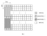
- FIG. 2 is a schematic diagram of a control resource set provided by an embodiment of the present application.
- FIG. 3 is a schematic diagram of a logical mapping relationship between a search space and a PDCCH candidate according to an embodiment of the present application
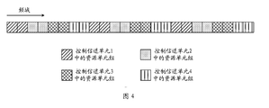
- FIG. 4 is a schematic diagram of discrete resource mapping of a CCE according to an embodiment of the present application.
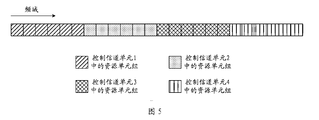
- FIG. 5 is a schematic diagram of centralized resource mapping of a CCE according to an embodiment of the present application.
- FIG. 6 is a schematic diagram of a method for transmitting control information according to an embodiment of the present application.
- FIG. 6A is a schematic diagram of a communication method according to an embodiment of the present application.
- FIG. 7 is a schematic structural diagram of a communication apparatus according to an embodiment of the present application.
- FIG. 8 is a schematic structural diagram of another communication apparatus according to an embodiment of the present application.
- FIG. 9 is a schematic structural diagram of another communication apparatus according to an embodiment of the present application.
- FIG. 10 is a schematic structural diagram of another communication apparatus according to an embodiment of the present application.
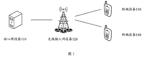
- FIG. 1 is a schematic structural diagram of a mobile communication system to which an embodiment of the present application is applied.
- the mobile communication system includes a core network device 110, a radio access network device 120, and at least one terminal device (such as the terminal device 130 and the terminal device 140 in FIG. 1).
- the terminal device is connected to the radio access network device by means of a wireless connection, and the radio access network device is connected to the core network device by wireless or wired.
- the core network device and the wireless access network device may be independent physical devices, or may integrate the functions of the core network device with the logical functions of the wireless access network device on the same physical device, or may be a physical device.
- the functions of some core network devices and the functions of some wireless access network devices are integrated.
- the terminal device can be fixed or mobile.
- FIG. 1 is only a schematic diagram, and the communication system may further include other network devices, such as a wireless relay device and a wireless backhaul device, which are not shown in FIG. 1.
- the embodiment of the present application does not limit the number of core network devices, radio access network devices, and terminal devices included in the mobile communication system.
- the radio access network device is an access device that the terminal device accesses to the mobile communication system by using a wireless device, and may be a base station NodeB, an evolved base station eNodeB, a 5G mobile communication system, or a new radio (NR) communication system.
- a radio access network device is referred to as a network device.
- a network device refers to a radio access network device.
- 5G and NR may be equivalent.
- the terminal device may also be referred to as a terminal terminal, a user equipment (UE), a mobile station (MS), a mobile terminal (MT), and the like.
- the terminal device can be a mobile phone, a tablet, a computer with wireless transceiver function, a virtual reality (VR) terminal device, an augmented reality (AR) terminal device, and an industrial control (industrial control).
- Wireless terminal wireless terminal in self driving, wireless terminal in remote medical surgery, wireless terminal in smart grid, wireless in transport safety A terminal, a wireless terminal in a smart city, a wireless terminal in a smart home, and the like.
- Radio access network equipment and terminal equipment can be deployed on land, including indoors or outdoors, handheld or on-board; they can also be deployed on the water; they can also be deployed on aircraft, balloons and satellites in the air.
- the application scenarios of the radio access network device and the terminal device are not limited.
- the embodiments of the present application can be applied to downlink signal transmission, and can also be applied to uplink signal transmission, and can also be applied to device to device (D2D) signal transmission.
- the transmitting device is a radio access network device, and the corresponding receiving device is a terminal device.
- the transmitting device is a terminal device, and the corresponding receiving device is a wireless access network device.
- the transmitting device is a terminal device, and the corresponding receiving device is also a terminal device.
- the embodiment of the present application does not limit the transmission direction of the signal.
- the radio access network device and the terminal device and the terminal device and the terminal device and the terminal device can communicate through a licensed spectrum, or can communicate through an unlicensed spectrum, or can simultaneously pass the licensed spectrum and Authorize the spectrum for communication.
- the radio access network device and the terminal device and the terminal device and the terminal device can communicate through the spectrum below 6G, or can communicate through the spectrum of 6G or higher, and can simultaneously use the spectrum below 6G and the spectrum above 6G. Communicate.
- the embodiment of the present application does not limit the spectrum resources used between the radio access network device and the terminal device.
- the following describes an example of a downlink transmission in which the device is a network device and the receiving device is a terminal device.
- the method in the present application can also be applied to an uplink transmission in which the transmission device is a terminal device, the reception device is a network device, and a D2D transmission to which the transmission device is a terminal device, and the reception device is also a terminal device.
- the network device can send data to the terminal device through the data channel.
- the parameters may include a modulation and coding scheme (MCS), a transport block size (TBS), a redundancy version (RV), and a hybrid automatic repeat request (hybrid automatic repeat request).
- MCS modulation and coding scheme
- TBS transport block size
- RV redundancy version
- HARQ hybrid automatic repeat request
- RA resource block assignment
- PCI precoding information
- PCI precoding indicator
- These transmission parameters may be predefined by a protocol, or may be sent by the network device to the terminal device through signaling.
- the signaling may include at least one of radio resource control (RRC) signaling, medium access control (MAC) layer signaling, and physical layer signaling, unless otherwise specified.
- RRC radio resource control
- MAC medium access control
- the terminal device can receive the data of the data channel and demodulate and decode the received data.
- the data channel may be a physical downlink shared channel (PDSCH), and the control parameters of the control data transmitted on the PDSCH are transmitted through a physical downlink control channel (PDCCH);
- the data channel may be a physical uplink shared channel (PUSCH), and control parameters for controlling the data transmission on the PUSCH are transmitted from the network device to the terminal device through the PDCCH.
- PDSCH physical downlink shared channel
- PUSCH physical uplink shared channel
- control channel is a PDCCH as an example
- data channel is described by taking a PDSCH as an example.
- control channel and the PDCCH may be equivalent, but the specific names of the control channel and the data channel are not limited in this application.
- PDCCH carries downlink control information (DCI)
- the scheduling information and other control information are carried on the PDCCH, and the information carried on the PDCCH may be collectively referred to as DCI.
- the above transmission parameters may be part of the DCI.
- the DCI payloads in different scenarios may be different in size, which may result in different DCI formats, and the resource size used to transmit the PDCCH may be different.
- the load size of the DCI for scheduling uplink data transmission and scheduling downlink data transmission may be different, and the load size of DCI for scheduling single stream downlink data transmission and scheduling multi-stream downlink data transmission may also be different.
- the aggregation level refers to the number of control channel elements (CCEs) used to carry one PDCCH.
- CCE is the basic unit of the physical resources of the control channel.
- a CCE is composed of multiple resource element groups (REGs): in a long term evolution (LTE) communication system, 9 REGs form a CCE; in an NR system, 6 REGs form a CCE.
- An REG is composed of a plurality of resource elements (REs): in an LTE system, four REs form one REG; in an NR system, one resource block (RB) in one OFDM symbol constitutes one REG.
- the RE consists of one subcarrier within one OFDM symbol and is the smallest physical time-frequency resource in the LTE system and the NR system.
- the symbols and the time domain symbols are equivalently interchangeable.
- An OFDM symbol is an example of a time domain symbol, but a time domain symbol is not limited to an OFDM symbol.
- aggregation levels 16 and 32 may also be used.
- the network side determines the aggregation level of the PDCCH according to factors such as the size of the DCI payload and the quality of the radio channel.
- the larger the DCI load the larger the aggregation level of the corresponding PDCCH.
- the possible format of the PDCCH is as shown in Table 1.
- PDCCH format Number of CCEs Number of REG Number of information bits in the PDCCH 0 1 9 72 1 2 18 144 2 4 36 288 3 8 72 576
- the number of CCEs per PDCCH is changed and there is no signaling, so the terminal device has to perform blind check on all possible aggregation levels of PDCCH candidates.
- the system can pre-define the aggregation level set. For example, a set of aggregation levels ⁇ 1, 2, 4, 8 ⁇ may be defined, that is, a network device may use one, two, four, or eight CCEs to transmit a PDCCH.
- the terminal equipment needs to separately aggregate levels.
- a blind check is performed on the PDCCHs 1, 2, 4, and 8 to confirm whether there is a PDCCH addressed to itself.
- the system defines a series of possible locations of PDCCHs in the control resource region for each aggregation level. These locations are called PDCCH candidates.
- the PDCCH candidate set that the terminal needs to monitor is called the search space.
- the PDCCH candidate set corresponding to a certain aggregation level is called the search space under the aggregation level.
- FIG. 2 exemplarily shows a control resource set (CORESET) related to the present application.
- a CORESET is a time-frequency resource in the control region.
- One CORESET corresponds to a group of user equipment (UE), for example, CORESET 1 corresponds to UE1, UE2, UE3 and UE4, and CORESET2 corresponds to UE4, UE5, UE6 and UE7.
- the PDCCHs of UE1, UE2, UE3, and UE4 may be transmitted on CORESET 1
- the PDCCHs of UE4, UE5, UE6, and UE7 may be transmitted on CORESET2.
- Each user has a search space on a CORESET whose resources are less than or equal to the resources of the CORESET.
- a user can correspond to multiple CORESETs, and the numerology on these CORESETs can be the same or different.
- the numerology here includes subcarrier spacing and cyclic prefix (CP) length.
- FIG. 3 exemplarily shows a logical mapping relationship between search space and PDCCH candidate.
- one UE has multiple search spaces of different aggregation levels.
- U2 in Figure 3 also has 4 search spaces of different aggregation levels.
- UE2's search space may overlap with UE1's search space, such as aggregation level 8 and aggregation level 2; UE2's search space and UE1
- the search space may also have no overlapping parts, such as aggregation level 4 and aggregation level 1.
- FIG. 3 also exemplarily shows a logical mapping relationship between PDCCH candidate and CCE.
- the system serially numbers the CCEs in the control area.
- the CCE number is a logical number used to uniquely determine the physical resource location of the CCE.
- the numbers of the CCEs constituting the PDCCH candidate are continuous and do not mean that the CCEs constituting the PDCCH candidate are contiguous in physical resources.
- CCE1, CCE2, CCE3, and CCE4 are respectively composed of six REGs that are discrete in the frequency domain.
- This resource mapping manner in which a plurality of discrete REGs form a CCE is called discrete resource mapping or distributed.
- Resource mapping For distributed resource mapping, the physical resources carrying one PDCCH are relatively dispersed in the frequency domain, so that the frequency diversity gain can be utilized to improve the robustness and transmission efficiency of the PDCCH transmission.
- CCE1, CCE2, CCE3, and CCE4 are respectively composed of six REGs in a frequency domain.
- This method of resource mapping in which a plurality of consecutive REGs form a CCE is called a localized resource mapping.
- the physical resources carrying one PDCCH are concentrated in the frequency domain, and the network device selects the frequency resource with better channel quality to carry the PDCCH through scheduling, so that the frequency selectivity of the wireless channel can be utilized to improve the transmission efficiency of the PDCCH. And transmission reliability.
- the time unit may be one of a time domain symbol, a mini-slot, a time slot, a subframe or a frame.
- resource concepts involved in the present application may refer to existing definitions (such as the existing provisions in the LTE standard and the NR communication system), but are not limited to the existing definitions.
- the definitions of these resource concepts in future communication standards may differ and do not affect the implementation of this application.
- the network device notifies the terminal device of the modulation order and the TBS information by the MCS index value in the MCS field in the DCI.
- the MCS field in DCI format 0 can be used to indicate the modulation order in the PUSCH and the TBS
- the MCS field in DCI format 1A can be used to indicate the modulation order in the PDSCH and the TBS.
- Table 2 shows the relationship between a possible MCS index value and the modulation order and TBS in the LTE system.
- the modulation order value of 2 indicates that the modulation mode is quadrature phase shift keying (QPSK), and the value of 4 indicates 16 quadrature amplitude modulation (QAM).
- QPSK quadrature phase shift keying
- QAM quadrature amplitude modulation
- a value of 6 indicates 64QAM.
- the TBS index combined with the allocated resource size determines the size of the transport block.
- the MCS field herein can be used to indicate that the PDSCH channel can also be used to indicate the PUSCH channel.
- the network device indicates the number of repetitions of the PDSCH or PUSCH by a repetition number field.
- a repetition number field For example, one possible indication method is to indicate the repetition times 1, 4, 8, 16, 32, 64, 128, and 192 by a repetition number field of 3 bits in length.
- the number of repetitions of a data channel or a control channel can also be understood as the number of repeated transmissions of a data channel or a control channel.
- the above indication method for indicating the MCS/TBS and the number of repetitions has certain information redundancy, which increases the transmission overhead of the PDCCH, and reduces the transmission reliability of the PDCCH when the transmission resources are constant.
- the transmission reliability requirements of the PDCCH and the PDSCH are the same.
- the transmission code rate of the PDCCH reflects the code rate required for PDSCH transmission to some extent.
- the code rate here refers to the number of information bits before channel coding divided by the number of bits that physical resources can carry.
- the modulation mode of the PDCCH is fixed to QPSK.
- the code rate of the PDCCH is determined by the number of CCEs transmitting the PDCCH.
- the code rate of the PDSCH is determined by the TBS, the modulation method, and the number of repetitions.
- the number of CCEs transmitting the PDCCH may reflect the TBS, the modulation scheme, and the number of repetitions of the PDSCH to a certain extent, so that the number of bits used to indicate the TBS, the modulation scheme, and the number of repetitions can be reduced by using the aggregation level information of the PDCCH.
- the transmission reliability of the PDCCH can be improved on the premise that the transmission resource of the PDCCH is constant. On the premise that the transmission reliability is constant, the transmission resource of the PDCCH can be reduced, and the transmission efficiency is improved.
- the present application provides a method for transmitting control information, which uses the aggregation level information of the PDCCH to reduce the payload size of the PDCCH, thereby effectively improving the transmission reliability of the PDCCH under the premise of a certain transmission resource.
- the network device determines first control information, where the first control information is used to control transmission of data on the data channel.
- the network device can schedule the data to be transmitted at intervals of, for example, every millisecond (millisecond, ms) or 0.1 ms, thereby determining the scheduling result: which terminal device is allocated resources, how large data blocks are transmitted, and which modulation is used.
- the mode is transmitted, which HARQ process is used for transmission, which rate matching parameter is used, the duration of data transmission, and the number of times data is repeatedly transmitted.
- the first control information includes transmission parameters for controlling data transmission on the PDSCH. After the terminal device obtains the transmission parameters, the terminal device can receive data on the PDSCH and perform data on the received data. Demodulation and decoding. For the uplink data transmission, the first control information includes a transmission parameter for controlling the transmission of the data on the PUSCH. After the terminal device obtains the parameters, the data can be transmitted through the PUSCH, and the network device can receive the PUSCH according to the parameters. Data, and demodulate and decode the received data.
- the first control information may include at least one of a first MCS index, a number of time units of data channel transmission, a number of repetitions of the data channel, a modulation order, a transport block size, and a code rate of the data channel.
- the first MCS index may be used to indicate the modulation order of the PDSCH and the TBS transmitted on the PDSCH.
- the number of repetitions of the data channel may be the frequency domain repetition number or the time domain repetition number, or may be the sum of the time domain and the frequency domain repetition number.
- the network device determines a resource size of the transmission control channel, where the control channel is used to carry the second control information.
- the control channel may be a PDCCH
- the resource size of the transmission control channel may be the number of CCEs that transmit the PDCCH.
- the network device needs to determine how many CCEs are used to transmit the PDCCH.
- the resource size herein may also be understood as an aggregation level, that is, the number of CCEs transmitting the PDCCH; when one PDCCH passes through two or more CORESETs.
- the resource size of the transmission control channel can be understood as the sum of the aggregation levels on each CORESET, that is, the total number of CCEs transmitting the PDCCH.
- the resource size of the transmission control channel may also be the number of repeated transmissions of the control channel; or may be a value obtained by mathematically processing the number of CCEs transmitting the control channel and the number of repeated transmissions of the control channel, for example, transmission.
- the resource size of the control channel is equal to the product of the number of CCEs transmitting the control channel and the number of repeated transmissions of the control channel. When the number of CCEs transmitting the control channel is 4, and the number of repeated transmissions of the control channel is 2, Then, the resource size of the transmission control channel is 8.
- the number of repeated transmissions of the control channel may be the number of repeated transmissions in the time domain, the number of repeated transmissions in the frequency domain, or the number of repeated transmissions in the time-frequency domain.
- the network device may determine the resource size of the transmission control channel according to at least one of a payload size of the control channel and a quality of the radio channel.
- the resource size of the transmission control channel is equal to the number of CCEs transmitting the PDCCH as an example.
- the network device determines second control information according to a resource size of the transmission control channel and first control information.
- the number of CCEs transmitting the PDCCH may also reflect the TBS, the modulation mode, and the number of repetitions of the PDSCH to a certain extent, so that the bits for indicating the TBS, the modulation mode, and the repetition number may be reduced by using the aggregation level information of the PDCCH. number.
- the MCS index in the first control information uses 5 bits to indicate the modulation order and TBS.
- the number of CCEs transmitting the PDCCH also reflects the range of channel quality, it can also indirectly reflect the modulation order of the PDSCH and the range of the TBS.
- the larger the number of CCEs transmitting the PDCCH the worse the channel quality at this time, the smaller the TBS that the PDSCH can transmit, and the lower the modulation order that can be used.
- the larger the number of transmission time units required the larger the number of repetitions required for the PDSCH. Therefore, with the number of CCEs transmitting the PDCCH, a smaller number of bits can be used to indicate the modulation order of the PDSCH and the TBS.
- the PDCCH carries the second control information, where the second control information may include the first indication information, where the first indication information is used to indicate the second MCS index.
- the first indication information may directly indicate the second MCS index by using the first field, where the first field is only used to indicate the second MCS index, and the first indication information may also be used to indicate the second MCS index by using the second field.
- the two fields are jointly encoded by the second MCS index and other information.
- the present application does not limit how to specifically indicate the second MCS index.
- the second MCS index is determined according to the number of CCEs transmitting the PDCCH and the first MCS index. There are at least two methods for determining the second MCS index according to the number of CCEs that transmit the PDCCH and the first MCS index:
- the reference value of one MCS index is determined according to the number of CCEs transmitting the PDCCH, and the second MCS index is an offset of the first MCS index based on the reference value of the MCS index.
- the reference value of the MCS index is 15. In this case, if the value of the second MCS index is 2, the corresponding first MCS index is 17 .
- the terminal device may determine the modulation order of the PDSCH and the TBS according to the first MCS index value.
- the determination of the reference value of the MCS index is related to the load size of the DCI in the PDCCH.
- the reference values of different MCS indexes can be set by using the same number of CCEs to transmit PDCCHs with different payload sizes. For example, if a 4-bit CCE is used to transmit a 200-bit PDCCH, the reference value of the MCS index may be set to 15; and using 4 CCEs to transmit a 400-bit PDCCH, the reference value of the MCS index may be set to 20. Because if the transmission quality of 400 bits using 4 CCEs is the same as the transmission quality of 200 bits using 4 CCEs, it means that the channel quality of a scenario using 4 CCEs for transmitting 400 bits is better than that of a scenario using 4 CCEs for transmitting 200 bits.
- the reference value of the MCS index of the scene using 4 CCEs for transmitting 400 bits can be set larger.
- the reference value of the MCS index corresponding to the number of different CCEs may be predefined by the protocol, or may be notified by the network device to the terminal device through signaling. It can be understood that Table 3 is only a schematic diagram of the mapping relationship between the resource size of the transmission control channel and the MCS index, and is not limited to the embodiment of the present application.
- the range of the value of the first MCS index is determined according to the number of CCEs that transmit the PDCCH, and the second MCS index is an index of the first MCS index. Since the number of CCEs can reflect the value range of the first MCS index, the number of bits required for the second MCS index is smaller than the first MCS index.
- Table 4 illustrates a method of renumbering the first MCS index to obtain a second MCS index. The correspondence between the second MCS index and the first MCS index may be predefined by a protocol, or notified to the terminal device by the network device by using signaling.
- Table 4 is only a schematic diagram of the mapping relationship between the resource size of the transmission control channel, the first MCS index, and the second MCS index, and is not limited to the embodiment of the present application.
- the mapping relationship may be in the form of a table in a specific implementation, or may be implemented by a branch selection or a judgment statement such as if else or switch case in a similar programming language C language.
- the mapping relationship is implemented in the form of a table, the present application does not limit the order of the columns in the table: as shown in Table 4, the first column is the resource size of the transmission control channel, and the second column is the first MCS index. The third column is the second MCS index.
- the first column may be the resource size of the transmission control channel, the second column is the second MCS index, and the third column is the first MCS index.
- mapping the first MCS index to the second MCS index may cause the number of bits in the PDCCH for indicating the MCS index to be effectively reduced, for example, from 5 bits to 3 bits or even 2 bits.
- the second control information may include second indication information, the second indication information being used to indicate an index of the number of time units of the data channel transmission.
- the second indication information may directly indicate, by using the third field, an index of the number of time units of the data channel transmission, where the third field is only used to indicate an index of the number of time units of the data channel transmission; the second indication information may also be
- the fourth field indicates an index of the number of time units of the data channel transmission, and the fourth field is jointly encoded by the index of the number of time units transmitted by the data channel and other information.
- the method for specifying how to index the number of time units of data channel transmission is not limited in this application.
- the network device determines an index of the number of time units of the data channel transmission in the second control information according to the number of CCEs transmitting the PDCCH and the number of time units of the data channel transmission in the first control information. Similar to the method for determining the second MCS index, the method for determining the index information of the number of time units of the data channel transmission in the second control information is at least the following two types:
- the reference value of the number of time units of the data channel transmission is determined according to the number of CCEs transmitting the PDCCH, and the index of the number of time units of the data channel transmission in the second control information is the time of the data channel transmission.
- the number of units is the offset based on the reference value of the number of units of the time.
- Table 5 when the number of CCEs transmitting the PDCCH is equal to 4, the reference value of the number of time units for data channel transmission is 4, and at this time, if the time unit of the data channel transmission in the first control information If the number is 6, the index of the number of time units of the data channel transmission in the corresponding second control information is 2. It can be understood that Table 5 is only a schematic diagram of the mapping relationship between the resource size of the transmission control channel and the reference value of the number of time units of the data channel transmission, and is not limited to the embodiment of the present application.
- the range of the number of time units of the data channel transmission is determined according to the number of CCEs transmitting the PDCCH, and the index of the number of time units of the data channel transmission in the second control information is an index within the range.
- Table 6 illustrates a method of obtaining an index of the number of time units of data channel transmission.
- the correspondence between the number of time units of the data channel transmission and the index may be predefined by a protocol, or notified to the terminal device by the network device by using signaling. It can be understood that Table 6 is only a schematic diagram of the mapping relationship between the resource size of the transmission control channel, the number of time units of the data channel transmission, and the index of the number of time units of the data channel transmission. The definition of the embodiment of the present application.
- the above process of mapping the number of time units of the data channel transmission to the index of the number of time units of the data channel transmission can effectively reduce the number of bits of the number of time units in the PDCCH for indicating the data channel transmission, For example, from bits to 2 bits.
- the second control information may include third indication information, and the third indication information is used to indicate an index of the number of repetitions of the data channel.
- the third indication information may directly indicate an index of the number of repetitions of the data channel by using the fifth field, where the fifth field is only used to indicate an index of the number of repetitions of the data channel; and the third indication information may also indicate the data by using the sixth field.
- An index of the number of repetitions of the channel obtained by jointly encoding the index of the number of repetitions of the data channel with other information.
- the method of the present application does not limit how to specifically indicate the index of the number of repetitions of the data channel.
- the network device determines index information of the number of repetitions of the data channel in the second control information according to the number of CCEs transmitting the PDCCH and the number of repetitions of the data channel in the first control information. Similar to the above method for determining the second MCS index, there are at least two methods for specifically determining the index information of the number of repetitions of the data channel in the second control information:
- the first type determines a reference value of the number of repetitions of the data channel according to the number of CCEs that transmit the PDCCH, and the index of the number of repetitions of the data channel in the second control information is that the number of repetitions of the data channel is based on the reference value.
- An offset As shown in Table 7, when the number of CCEs transmitting the PDCCH is equal to 4, the reference value of the number of repetitions of the data channel is 4, and if the number of repetitions of the data channel in the first control information is 6, the corresponding The index of the number of repetitions of the data channel in the second control information is 2. It can be understood that Table 7 is only a schematic diagram of the mapping relationship between the resource size of the transmission control channel and the reference value of the number of repetitions of the data channel, and is not limited to the embodiment of the present application.
- Resource size of the transmission control channel Reference value of the number of repetitions of the data channel 1 1 2 2 4 4 8 8 16 16 32 32
- the range of the number of repetitions of the data channel is determined according to the number of CCEs transmitting the PDCCH, and the index of the number of repetitions of the data channel in the second control information is an index within the range.
- Table 8 illustrates a method of obtaining an index of the number of repetitions of a data channel. The correspondence between the number of repetitions of the data channel and the index may be predefined by a protocol, or notified to the terminal device by the network device by using signaling. It can be understood that Table 8 is only a schematic diagram of the mapping relationship between the resource size of the transmission control channel, the number of repetitions of the data channel, and the index of the number of repetitions of the data channel, and is not limited to the embodiment of the present application.
- the above-described process of mapping the number of repetitions of the data channel to the index of the number of repetitions of the data channel can effectively reduce the number of bits in the PDCCH for indicating the number of repetitions of the data channel, for example, from 3 bits to 2 bits.
- the second control information includes information indicating the second MCS index, index information indicating the number of time units of the data channel transmission, and index information indicating the number of repetitions of the data channel may be independent fields. That is, the second control information includes a second MCS index value field, an index value field of the number of time units of the data channel transmission, and a repetition number index field of the data channel. At this time, it can also be understood that the second control information includes the second.
- the second control information may also include a field for indicating at least two items of the second MCS index, the number of time units of the data channel transmission, and the number of repetitions of the data channel, for example, the second MCS may be used.
- the index, the index of the number of time units of the data channel transmission, and at least two of the number of repetitions of the data channel are jointly coded or jointly mapped.
- the second control information may also include index information of the modulation order, index information of the transport block size, and index information of the code rate of the data channel.
- the network device determines, according to the number of CCEs that transmit the PDCCH, the modulation order in the first control information, the transport block size, and the code rate of the data channel, the index information of the modulation order in the second control information, and the index information of the transport block size. Index information of the code rate of the data channel. Similar to the method of determining the information of the second MCS index, the details are not described herein.
- the network device may further determine the second control information according to the resource mapping manner of the CCE, that is, determine the second control information according to the resource size of the transmission control channel, the resource mapping manner of the CCE, and the first control information.
- the resource mapping manner of the CCE herein includes a discrete resource mapping manner as shown in FIG. 4 and a centralized resource mapping manner as shown in FIG. 5.
- two sets of independent mapping relationships as shown in Tables 3 to 8 can be defined for the discrete resource mapping mode and the centralized resource mapping mode, so that the network device and the terminal device can be based on the resource size of the transmission control channel.
- the resource mapping manner of the CCE and the first control information determine the second control information.
- the resource mapping mode of the CCE may be a protocol pre-defined, or the network device may notify the terminal device by signaling.
- the network device sends a control channel, where the control channel carries the second control information.
- the second control information is sent to the terminal device through the control channel.
- the network device encodes and modulates the data according to the first control information, and then transmits the coded modulated data to the terminal device through the data channel.
- the terminal device receives the control channel and detects the control channel, and determines a resource size of the transmission control channel.
- the terminal device receives the control channel, performs blind detection on the PDCCH in a search space on different aggregation levels, and determines whether there is a PDCCH sent to itself, and determines a resource size for transmitting the PDCCH.
- the aggregation level supported by the terminal device is configured by the network device to the terminal device by protocol agreement or by signaling.
- the terminal device After the terminal device blindly detects the PDCCH in the search space, the terminal device demodulates and decodes the PDCCH, acquires second control information, and determines the first control information according to the second control information and the resource size.
- the terminal device may use the resource size of the transmission control channel, the resource mapping manner of the CCE, and The second control information determines the first control information.
- the terminal device specifically determines the first control information, which can be directly obtained by referring to step S630, which is specifically described as follows.
- the terminal device may determine the first MCS index according to the resource size of the transmission control channel and the second MCS index.
- the second MCS index may be an offset of the first MCS index based on the MCS index reference value, and the reference value of the MCS index is determined according to the resource size of the transmission control channel.
- Table 3 shows the mapping relationship between the reference value of one possible MCS index and the resource size of the transmission control channel.
- the second MCS index may also be an index of the first MCS index.
- Table 4 shows the mapping relationship between the resource size of the possible transmission control channel, the first MCS index, and the second MCS index.
- the terminal device may determine, according to the resource size of the transmission control channel and the index of the number of time units of the data channel transmission. The number of time units transmitted by the data channel.
- the index of the number of time units of the data channel transmission may be an offset of the number of time units of the data channel transmission based on the reference value of the number of time units, and the reference value of the number of time units is according to the transmission control channel.
- the size of the resource is determined. Table 5 is a mapping relationship between a resource size of a possible transmission control channel and a reference value of the number of time units of data channel transmission. After obtaining the resource size of the transmission control channel, the terminal device determines the number of time units of the data channel transmission according to the mapping relationship between the resource size of the transmission control channel and the reference value of the number of time units of the data channel transmission. The reference value can then determine the number of time units of the data channel transmission based on the reference value of the number of time units of the data channel transmission and the index of the number of time units of the data channel transmission.
- the index of the number of time units of the data channel transmission may also have a mapping relationship as shown in Table 6 between the resource size of the transmission control channel and the number of time units of the data channel transmission.
- the terminal device After obtaining the resource size of the transmission control channel, the terminal device performs a mapping relationship between the resource size of the transmission control channel, the number of time units of the data channel transmission, and the index of the number of time units of the data channel transmission. And the resource size of the transmission control channel and the number index of the time unit of the data channel transmission can determine the number of time units of the data channel transmission.
- the terminal device may determine the number of repetitions of the data channel according to the resource size of the transmission control channel and the repetition number index of the data channel.
- the repetition number index of the data channel may be an offset of the number of repetitions of the data channel based on the reference value of the number of repetitions, and the reference value of the number of repetitions is determined according to the resource size of the transmission control channel.
- Table 7 shows the mapping relationship between the resource size of a possible transmission control channel and the reference value of the number of repetitions.
- the index of the number of repetitions of the data channel may also have a mapping relationship as shown in Table 8 between the resource size of the transmission control channel and the number of repetitions of the data channel.
- the terminal device maps the relationship between the resource size of the transmission control channel, the number of repetitions of the data channel, and the number of repetitions of the data channel, and the resource size of the transmission control channel.
- the index of the number of repetitions of the data channel can determine the number of repetitions of the data channel.
- the terminal device may demodulate and decode the data on the data channel according to the first control information.
- the present application further provides a communication method for implicitly indicating the number of time units of data channel transmission and the number of repeated transmissions of data channels by the size of resources of the transmission control channel.
- the number of repeated transmissions of the data channel and the number of repetitions of the data channel can be interchangeably equivalent.
- the network device determines a resource size of the transmission control channel, the control channel carries a first parameter, and the first parameter is used to control transmission of data on the data channel.
- the first parameter may include information such as MCS and TBS.
- the size of the resource of the transmission control channel reflects the quality of the radio channel to some extent
- the number of time units of the data channel transmission and the number of repeated transmissions of the data channel also reflect the quality of the radio channel to some extent.
- a possible solution is to establish a first mapping relationship between the size of the resource of the transmission control channel and the number of repeated transmissions of the data channel, and establish a second between the size of the resource of the transmission control channel and the number of time units of the data channel transmission.
- the mapping relationship, the first mapping relationship and/or the second mapping relationship may be predefined or semi-statically configured to the terminal device by using RRC signaling, so that the number of bits of the first parameter may be reduced.
- Resource size of the transmission control channel Number of time units transmitted by the data channel 1 1 2 2 4 4 8 8 16 16 32 32
- the network device sends a control channel and a data channel. Specifically, the network device transmits the control channel according to the determined resource size of the transmission control channel, and transmits the data channel according to the determined time unit of the data channel transmission and/or the repeated transmission times of the data channel.
- S6A-3 The terminal device receives the control channel and detects the control channel, and determines the resource size of the transmission control channel. A more specific description can be referred to S650.
- the terminal device determines a number of time units for data channel transmission according to a mapping relationship between a resource size of the transmission control channel and a number of time units of the data channel transmission, and a resource size of the transmission control channel; and/or ,
- the terminal device determines the number of repeated transmissions of the data channel according to the mapping relationship between the resource size of the transmission control channel and the number of repeated transmissions of the data channel, and the resource size of the transmission control channel.
- the number of time units of the data channel transmission and/or the number of repeated transmissions of the data channel need not be indicated to the terminal device through the first parameter in the control channel, thereby effectively reducing the payload size of the control channel. Improve the transmission efficiency and reliability of the control channel.
- the communication method provided by the embodiment of the present application is introduced from the perspective of the interaction between the network device as the transmitting device, the terminal device as the receiving device, and the sending device and the receiving device.
- various devices such as a transmitting device and a receiving device, etc., in order to implement the above functions, include hardware structures and/or software modules corresponding to the respective functions.
- the present application can be implemented in a combination of hardware or hardware and computer software in combination with the elements and method steps of the various examples described in the embodiments disclosed herein. Whether a function is implemented in hardware or computer software to drive hardware depends on the specific application and design constraints of the solution. A person skilled in the art can use different methods to implement the described functions for each particular application, but such implementation should not be considered to be beyond the scope of the present application.
- the communication device implements the functions of the network device as the transmitting device in the foregoing method embodiments of FIG. 6 and FIG. 6A, and thus can also achieve the beneficial effects of the foregoing method embodiments.
- the communication device may be the radio access network device 120 as shown in FIG.
- the communication device 700 includes a processing unit 710 and a transmitting unit 720.
- the processing unit 710 is configured to determine first control information, where the first control information is used to control transmission of data on the data channel.
- the processing unit 710 is further configured to determine a resource size of the transmission control channel, where the control channel is used to carry the second control information.
- the processing unit 710 is further configured to determine second control information according to the resource size and the first control information;
- the sending unit 720 is configured to send the second control information on the control channel.
- the processing unit 710 is further configured to: according to the resource size of the transmission control channel and the first modulation and coding scheme index
- the second modulation coding scheme index is determined.
- the second modulation and coding scheme index may be an index of the first modulation and coding scheme index.
- the processing unit 710 is further configured to: according to the resource size And determining, by the number of time units of the data channel transmission in the first control information, index information of the number of time units of the data channel transmission in the second control information.
- the resource size of the transmission control channel is the number of control channel units used for transmitting the control channel or the number of repeated transmissions of the control channel.
- the control channel unit belongs to at least one control resource set.
- the processing unit 710 is configured to determine a resource size of the transmission control channel, where the control channel carries a first parameter, and the first parameter is used to control transmission of data on the data channel. There is a first mapping relationship between the resource size of the transmission control channel and the number of repeated transmissions of the data channel; and/or there is a second mapping relationship between the resource size of the transmission control channel and the number of time units of the data channel transmission.
- the transmitting unit 720 is configured to send a control channel and a data channel.
- the first mapping relationship is predefined, or the sending unit 720 is further configured to notify the terminal device of the first mapping relationship by using the RRC message.
- the second mapping relationship is predefined, or the sending unit 720 is further configured to notify the terminal device of the first mapping relationship by using the RRC message.
- the resource size of the transmission control channel is the product of the number of control channel elements used for the transmission control channel or the number of repeated transmissions of the control channel or the number of control channel elements used for transmitting the control channel and the number of repeated transmissions of the control channel.
- the control channel unit belongs to at least one control resource set.
- the number of repeated transmissions of the control channel is the number of repeated transmissions of the control channel in the time domain, or the number of repeated transmissions of the control channel in the frequency domain.
- communication device 800 includes a processor 810, a transceiver 820, and a memory 830, wherein memory 830 can be used to store code executed by processor 810.
- the various components in communication device 800 communicate with one another via internal connection paths, such as by control and/or data signals over the bus.
- the processor 810 is configured to perform the functions of the processing unit 710
- the transceiver 820 is configured to perform the functions of the transmitting unit 720.
- processing unit 710 the processor 810, the transmitting unit 720, and the transceiver 820 may be directly obtained by referring to the method embodiments shown in FIG. 6 and FIG. 6A above.
- the information sending function in the foregoing method embodiment is completed by the sending unit 720 or the transceiver 820, and the remaining data processing functions are all completed by the processing unit 710 or the processor 810, and no further details are provided herein.
- FIG. 9 and 10 are schematic structural diagrams of two other possible communication devices according to an embodiment of the present application.
- the communication device implements the functions of the terminal device as the receiving device in the method embodiment shown in FIG. 6 and FIG. 6A described above, and thus the advantageous effects of the above method embodiments can also be achieved.
- the communication device may be the terminal device 130 or the terminal device 140 as shown in FIG. 1.
- the communication device 900 includes a receiving unit 910 and a processing unit 920.
- the receiving unit 910 is configured to receive a control channel, where the control channel is configured to carry second control information;
- the processing unit 920 is configured to detect the control channel, determine a resource size for transmitting the control channel,
- the processing unit 920 is further configured to acquire the second control information by using the control channel, and determine the first control information according to the second control information and the resource size, where the first control information is used to control data. Transmission on the data channel.
- the processing unit 920 is further configured to: according to the resource size of the transmission control channel and the second modulation and coding scheme index A first modulation coding scheme index is determined.
- the second modulation and coding scheme index may be an index of the first modulation and coding scheme index.
- the processing unit 920 is further configured to: according to the resource size and location The index information of the number of time units of the data channel transmission in the second control information determines the number of time units of the data channel transmission in the first control information.
- the resource size of the transmission control channel is the number of control channel units used for transmitting the control channel or the number of repeated transmissions of the control channel.
- the control channel unit belongs to at least one control resource set.
- the receiving unit 910 is configured to receive a control channel, where the control channel carries a first parameter, where the first parameter is used to control transmission of data on the data channel.
- the processing unit 920 is configured to detect a control channel and determine a resource size of the transmission control channel.
- the processing unit 920 is further configured to determine, according to the first mapping relationship and the resource size of the transmission control channel, the number of repeated transmissions of the data channel, where the first mapping relationship is a mapping relationship between a resource size of the transmission control channel and a repeated transmission number of the data channel; and / or,
- the processing unit 920 is further configured to determine, according to the second mapping relationship and the resource size of the transmission control channel, the number of time units of the data channel transmission, where the second mapping relationship is a resource size of the transmission control channel and a number of time units of the data channel transmission. The mapping relationship between them.
- the receiving unit 910 is further configured to receive the data channel according to the number of repeated transmissions of the data channel and/or the number of time units of the data channel transmission.
- the first mapping relationship is predefined, or the receiving unit 910 is further configured to acquire the first mapping relationship by receiving a radio resource control message from the network device.
- the second mapping relationship is predefined, or the receiving unit 910 is further configured to obtain the first mapping relationship by receiving a radio resource control message from the network device.
- the resource size of the transmission control channel is the product of the number of control channel elements used for the transmission control channel or the number of repeated transmissions of the control channel or the number of control channel elements used for transmitting the control channel and the number of repeated transmissions of the control channel.
- the control channel unit belongs to at least one control resource set.
- the number of repeated transmissions of the control channel is the number of repeated transmissions of the control channel in the time domain, or the number of repeated transmissions of the control channel in the frequency domain.
- the communication device 1000 includes a processor 1020, a transceiver 1010, and a memory 1030, wherein the memory 1030 can be used to store code executed by the processor 1020.
- the various components in the communication device 1000 communicate with one another via internal connection paths, such as by control and/or data signals over the bus.
- the processor 1020 is configured to perform the functions of the processing unit 920
- the transceiver 1010 is configured to perform the functions of the receiving unit 910.
- receiving unit 910 the transceiver 1010, the processing unit 920, and the processor 1020 described above can be directly obtained by referring to the method embodiments shown in FIG. 6 and FIG. 6A above.
- the information receiving function in the foregoing method embodiment is completed by the receiving unit 910 or the transceiver 1010, and the remaining data processing functions are all completed by the processing unit 920 or the processor 1020, and are not described herein.
- Figures 8 and 10 only show one design of the communication device.
- the communication device can include any number of receivers and processors, and all communication devices that can implement embodiments of the present application are within the scope of the present application.
- FIGS. 7 to 10 are obtained by referring to the partial method embodiments shown in FIG. 6 and FIG. 6A above. It is to be understood that, with reference to other method embodiments of the present application and the device embodiments shown in FIG. 7 to FIG. 10, device embodiments corresponding to other method embodiments of the present application may be obtained, and are not described herein.
- the network device chip implements the functions of the network device in the foregoing method embodiment.
- the network device chip sends the second control information to other modules in the network device, such as a radio frequency module or an antenna.
- the second control information is sent to the terminal device via other modules of the network device.
- the terminal device chip When the embodiment of the present application is applied to a terminal device chip, the terminal device chip implements the function of the terminal device in the foregoing method embodiment.
- the terminal device chip receives the second control information from other modules (such as a radio frequency module or an antenna) in the terminal device, where the second control information is sent by the network device to the terminal device.
- the method and apparatus in the embodiments of the present application are applicable to the transmission of control information of a URLLC service, but this is also a limitation of the scope of application of the present application.
- the method and apparatus in the embodiments of the present application are also applicable to the transmission of control information of the mMTC service and the eMBB service.
- processors in the embodiment of the present application may be a central processing unit (CPU), and may be other general-purpose processors, digital signal processors (DSPs), and application specific integrated circuits. (Application Specific Integrated Circuit, ASIC), Field Programmable Gate Array (FPGA) or other programmable logic device, transistor logic device, hardware component, or any combination thereof.
- a general purpose processor can be a microprocessor or any conventional processor.
- the method steps in the embodiments of the present application may be implemented by means of hardware, or may be implemented by a processor executing software instructions.
- the software instructions can be composed of corresponding software modules, which can be stored in random access memory (RAM), flash memory, read-only memory (ROM), programmable read-only memory (Programmable ROM). , PROM), Erasable PROM (EPROM), Electrically Erasable Programmable Read Only Memory (EEPROM), Register, Hard Disk, Mobile Hard Disk, CD-ROM, or well known in the art Any other form of storage medium.
- An exemplary storage medium is coupled to the processor to enable the processor to read information from, and write information to, the storage medium.
- the storage medium can also be an integral part of the processor.
- the processor and the storage medium can be located in an ASIC. Additionally, the ASIC can be located in a transmitting device or a receiving device. Of course, the processor and the storage medium can also exist as discrete components in the transmitting device or the receiving device.
- the computer program product includes one or more computer instructions.
- the computer can be a general purpose computer, a special purpose computer, a computer network, or other programmable device.
- the computer instructions can be stored in or transmitted by a computer readable storage medium.
- the computer instructions can be from a website site, computer, server or data center to another website site by wire (eg, coaxial cable, fiber optic, digital subscriber line (DSL)) or wireless (eg, infrared, wireless, microwave, etc.) Transfer from a computer, server, or data center.
- the computer readable storage medium can be any available media that can be accessed by a computer or a data storage device such as a server, data center, or the like that includes one or more available media.
- the usable medium may be a magnetic medium (eg, a floppy disk, a hard disk, a magnetic tape), an optical medium (eg, a DVD), or a semiconductor medium (eg, a Solid State Disk (SSD)) or the like.
- plural refers to two or more.
- the term “and/or” in this context is merely an association describing the associated object, indicating that there may be three relationships, for example, A and/or B, which may indicate that A exists separately, and both A and B exist, respectively. B these three situations.
- the character “/” in this article generally indicates that the contextual object is an “or” relationship; in the formula, the character “/” indicates that the contextual object is a "divide” relationship.
Landscapes
- Engineering & Computer Science (AREA)
- Signal Processing (AREA)
- Computer Networks & Wireless Communication (AREA)
- Quality & Reliability (AREA)
- Mobile Radio Communication Systems (AREA)
Abstract
Priority Applications (3)
| Application Number | Priority Date | Filing Date | Title |
|---|---|---|---|
| BR112019028136-3A BR112019028136A2 (pt) | 2017-07-14 | 2018-07-13 | método e dispositivo de comunicação |
| EP18831937.0A EP3627940B1 (fr) | 2017-07-14 | 2018-07-13 | Procédé et dispositif de communication |
| US16/719,413 US11444737B2 (en) | 2017-07-14 | 2019-12-18 | Communication method and device |
Applications Claiming Priority (2)
| Application Number | Priority Date | Filing Date | Title |
|---|---|---|---|
| CN201710575692.6 | 2017-07-14 | ||
| CN201710575692.6A CN109257820B (zh) | 2017-07-14 | 2017-07-14 | 通信方法和设备 |
Related Child Applications (1)
| Application Number | Title | Priority Date | Filing Date |
|---|---|---|---|
| US16/719,413 Continuation US11444737B2 (en) | 2017-07-14 | 2019-12-18 | Communication method and device |
Publications (1)
| Publication Number | Publication Date |
|---|---|
| WO2019011307A1 true WO2019011307A1 (fr) | 2019-01-17 |
Family
ID=65001932
Family Applications (1)
| Application Number | Title | Priority Date | Filing Date |
|---|---|---|---|
| PCT/CN2018/095535 WO2019011307A1 (fr) | 2017-07-14 | 2018-07-13 | Procédé et dispositif de communication |
Country Status (5)
| Country | Link |
|---|---|
| US (1) | US11444737B2 (fr) |
| EP (1) | EP3627940B1 (fr) |
| CN (1) | CN109257820B (fr) |
| BR (1) | BR112019028136A2 (fr) |
| WO (1) | WO2019011307A1 (fr) |
Cited By (1)
| Publication number | Priority date | Publication date | Assignee | Title |
|---|---|---|---|---|
| WO2021196119A1 (fr) * | 2020-04-02 | 2021-10-07 | 华为技术有限公司 | Procédé et appareil de transmission de données |
Families Citing this family (10)
| Publication number | Priority date | Publication date | Assignee | Title |
|---|---|---|---|---|
| JP2019075609A (ja) * | 2017-10-12 | 2019-05-16 | シャープ株式会社 | 端末装置、基地局装置、および、通信方法 |
| US11425702B2 (en) * | 2018-08-06 | 2022-08-23 | Qualcomm Incorporated | Repetition configuration determination |
| US10892858B2 (en) * | 2018-09-28 | 2021-01-12 | At&T Intellectual Property I, L.P. | Chain broadcasting in vehicle-to-everything (V2X) communications |
| WO2020164140A1 (fr) * | 2019-02-15 | 2020-08-20 | 华为技术有限公司 | Procédé de communication et appareil |
| CN111601382B (zh) * | 2019-02-20 | 2022-12-13 | 华为技术有限公司 | 一种数据传输方法及通信装置 |
| CN111866920B (zh) * | 2019-04-30 | 2022-03-29 | 中国信息通信研究院 | 一种物理上行共享信道发送方法和设备 |
| CN111867066B (zh) * | 2019-04-30 | 2023-04-07 | 大唐移动通信设备有限公司 | 一种信息指示和确定指示信息的方法及设备 |
| US11888674B2 (en) * | 2020-02-14 | 2024-01-30 | Qualcomm Incorporated | 16-quadrature amplitude modulation (16-QAM) downlink configuration |
| US10972958B1 (en) | 2020-03-05 | 2021-04-06 | At&T Intellectual Property I, L.P. | Location-based route management for vehicle-to-everything relay communications |
| CN113660648B (zh) * | 2021-08-13 | 2024-04-05 | Oppo广东移动通信有限公司 | 多媒体数据的传输方法、装置、电子设备及存储介质 |
Citations (4)
| Publication number | Priority date | Publication date | Assignee | Title |
|---|---|---|---|---|
| CN101500259A (zh) * | 2008-01-30 | 2009-08-05 | 大唐移动通信设备有限公司 | 在高速共享数据信道上重传数据的方法、系统及装置 |
| CN104518843A (zh) * | 2013-09-27 | 2015-04-15 | 中兴通讯股份有限公司 | 公有消息发送、接收方法、装置及系统 |
| CN106717030A (zh) * | 2014-09-26 | 2017-05-24 | 阿尔卡特朗讯 | 用于防止消息冲突的方法和装置 |
| WO2017119467A1 (fr) * | 2016-01-08 | 2017-07-13 | 株式会社Nttドコモ | Dispositif d'utilisateur, station de base, procédé de réception de signal et procédé d'émission de signal |
Family Cites Families (19)
| Publication number | Priority date | Publication date | Assignee | Title |
|---|---|---|---|---|
| US8842628B2 (en) * | 2011-09-12 | 2014-09-23 | Blackberry Limited | Enhanced PDCCH with transmit diversity in LTE systems |
| WO2013180405A1 (fr) * | 2012-05-29 | 2013-12-05 | 엘지전자 주식회사 | Procédé pour la transmission et la réception de canaux de commande sur la liaison descendante dans des systèmes de communication sans fil, et appareil pour la mise en œuvre d'un tel procédé |
| EP2693677A1 (fr) * | 2012-08-02 | 2014-02-05 | Fujitsu Limited | E-PDCCH pour LTE Advanced communication sans fil |
| US9635644B2 (en) * | 2012-08-10 | 2017-04-25 | Qualcomm Incorporated | Downlink coverage enhancements |
| CN103929266B (zh) * | 2013-01-15 | 2019-08-09 | 中兴通讯股份有限公司 | 控制信道传输、传输处理方法及装置、网络侧设备、终端 |
| US9420576B2 (en) * | 2013-04-23 | 2016-08-16 | Qualcomm Incorporated | PDSCH transmission schemes with compact downlink control information (DCI) format in new carrier type (NCT) in LTE |
| CN109982444B (zh) * | 2013-07-26 | 2022-10-21 | Lg 电子株式会社 | 发送用于mtc的信号的方法及其设备 |
| WO2015046830A1 (fr) * | 2013-09-30 | 2015-04-02 | 주식회사 케이티 | Procédé d'émission-réception d'un canal de données de liaison descendante et appareil associé |
| US9667386B2 (en) * | 2013-11-13 | 2017-05-30 | Samsung Electronics Co., Ltd | Transmission of control channel and data channels for coverage enhancements |
| US9973303B2 (en) * | 2013-12-20 | 2018-05-15 | Samsung Electronics Co., Ltd. | Determining timing for transmission or reception of signaling in a coverage enhanced operating mode |
| CN108076432B (zh) * | 2013-12-27 | 2020-05-08 | 华为技术有限公司 | 广播控制带宽分配和数据收发方法及装置 |
| US9955465B2 (en) * | 2014-10-03 | 2018-04-24 | Intel IP Corporation | Downlink control information (DCI) design for LTE devices |
| US20160219587A1 (en) * | 2015-01-28 | 2016-07-28 | Mediatek Inc. | Control Channel and Data Channel Design for User Equipment |
| WO2016119232A1 (fr) * | 2015-01-30 | 2016-08-04 | Mediatek Singapore Pte. Ltd. | Procédés de détermination du nombre de répétitions d'un canal de données physique |
| EP3051728A1 (fr) * | 2015-01-30 | 2016-08-03 | Alcatel Lucent | Procédé pour fournir un taux de répétition |
| US20180198650A1 (en) * | 2017-01-06 | 2018-07-12 | Sharp Laboratories Of America, Inc. | User equipments, base stations and methods |
| US11006425B2 (en) * | 2017-02-03 | 2021-05-11 | Apple Inc. | Mechanisms to handle DL (downlink) control and data channels with different numerologies in NR (new radio) |
| KR102373791B1 (ko) * | 2017-05-04 | 2022-03-14 | 삼성전자주식회사 | 통신 시스템에서 제어 정보 탐색 및 데이터 정보 전송을 위한 방법 및 장치 |
| US20210377951A1 (en) * | 2020-05-29 | 2021-12-02 | Qualcomm Incorporated | Facilitating multi-cluster control resource sets for downlink control channel repetition |
-
2017
- 2017-07-14 CN CN201710575692.6A patent/CN109257820B/zh active Active
-
2018
- 2018-07-13 WO PCT/CN2018/095535 patent/WO2019011307A1/fr unknown
- 2018-07-13 EP EP18831937.0A patent/EP3627940B1/fr active Active
- 2018-07-13 BR BR112019028136-3A patent/BR112019028136A2/pt not_active IP Right Cessation
-
2019
- 2019-12-18 US US16/719,413 patent/US11444737B2/en active Active
Patent Citations (4)
| Publication number | Priority date | Publication date | Assignee | Title |
|---|---|---|---|---|
| CN101500259A (zh) * | 2008-01-30 | 2009-08-05 | 大唐移动通信设备有限公司 | 在高速共享数据信道上重传数据的方法、系统及装置 |
| CN104518843A (zh) * | 2013-09-27 | 2015-04-15 | 中兴通讯股份有限公司 | 公有消息发送、接收方法、装置及系统 |
| CN106717030A (zh) * | 2014-09-26 | 2017-05-24 | 阿尔卡特朗讯 | 用于防止消息冲突的方法和装置 |
| WO2017119467A1 (fr) * | 2016-01-08 | 2017-07-13 | 株式会社Nttドコモ | Dispositif d'utilisateur, station de base, procédé de réception de signal et procédé d'émission de signal |
Non-Patent Citations (2)
| Title |
|---|
| "Cellular System Support for Ultra-Low Complexity and Low Throughput Internet of Things (CIoT) (Release 13", 3 GPP; TECHNICAL SPECIFICATION GROUP GSM/EDGE RADIO ACCESS NETWORK, vol. GERAN WG1, 18 December 2015 (2015-12-18), pages 1 - 495, XP051047128 * |
| See also references of EP3627940A4 |
Cited By (1)
| Publication number | Priority date | Publication date | Assignee | Title |
|---|---|---|---|---|
| WO2021196119A1 (fr) * | 2020-04-02 | 2021-10-07 | 华为技术有限公司 | Procédé et appareil de transmission de données |
Also Published As
| Publication number | Publication date |
|---|---|
| US20200145165A1 (en) | 2020-05-07 |
| EP3627940A4 (fr) | 2020-05-20 |
| CN109257820B (zh) | 2021-12-03 |
| US11444737B2 (en) | 2022-09-13 |
| EP3627940A1 (fr) | 2020-03-25 |
| BR112019028136A2 (pt) | 2020-07-28 |
| CN109257820A (zh) | 2019-01-22 |
| EP3627940B1 (fr) | 2022-02-23 |
Similar Documents
| Publication | Publication Date | Title |
|---|---|---|
| US11444737B2 (en) | Communication method and device | |
| AU2022224872B2 (en) | Method and apparatus for partial retransmission in wireless cellular communication system | |
| CN109600836B (zh) | 信息传输方法和装置 | |
| CN113796142B (zh) | 在无线通信系统中发送和接收旁路控制信息的方法和装置 | |
| US11870566B2 (en) | Method and device for transmitting and receiving control information in wireless cellular communication system | |
| EP2947806B1 (fr) | Procédé de transmission/réception de données et appareil terminal à faible coût dans un système de communication mobile | |
| US11310779B2 (en) | Method and apparatus for transmitting/receiving control information in wireless communication system | |
| US11039430B2 (en) | Method and device for setting control and data channel transmission time in wireless communication system | |
| US20210250159A1 (en) | Resource configuration method and apparatus | |
| US11337188B2 (en) | Method and device for transmitting/receiving uplink control information in wireless communication system | |
| CN111989963A (zh) | 用于在无线通信系统中发送或接收同步信号的方法和装置 | |
| US11864188B2 (en) | Method and apparatus for scheduling and transmitting data in wireless cellular communication system | |
| WO2021032015A1 (fr) | Procédé de transmission d'informations de rétroaction et appareil de communication | |
| WO2020169063A1 (fr) | Procédé de transmission de données, et appareil de communication | |
| CN113517946A (zh) | 一种通信方法及装置 | |
| WO2021031948A1 (fr) | Procédé de traitement de données et appareil de communication | |
| WO2021032003A1 (fr) | Procédé de transmission d'informations de commande de liaison montante et appareil de communication | |
| WO2021000937A1 (fr) | Procédé de transmission à multiples unités de temps et appareil associé | |
| WO2022110086A1 (fr) | Procédé et appareil de communication, et support d'enregistrement lisible par ordinateur | |
| CN111669251B (zh) | 传输块大小的确定方法及通信装置 | |
| CN114390698A (zh) | 一种数据传输的方法、装置、介质以及程序产品 | |
| WO2023051173A1 (fr) | Procédé de transmission de données et appareil associé | |
| WO2024059984A1 (fr) | Procédé et appareil de détermination de taille de bloc de transport, dispositif et support de stockage | |
| US20210410006A1 (en) | Method for determining transport block size and communications apparatus | |
| WO2023284647A1 (fr) | Procédé et appareil de transmission d'informations |
Legal Events
| Date | Code | Title | Description |
|---|---|---|---|
| 121 | Ep: the epo has been informed by wipo that ep was designated in this application |
Ref document number: 18831937 Country of ref document: EP Kind code of ref document: A1 |
|
| REG | Reference to national code |
Ref country code: BR Ref legal event code: B01A Ref document number: 112019028136 Country of ref document: BR |
|
| ENP | Entry into the national phase |
Ref document number: 2018831937 Country of ref document: EP Effective date: 20191220 |
|
| NENP | Non-entry into the national phase |
Ref country code: DE |
|
| ENP | Entry into the national phase |
Ref document number: 112019028136 Country of ref document: BR Kind code of ref document: A2 Effective date: 20191227 |