WO2018235672A1 - 保持装置 - Google Patents
保持装置 Download PDFInfo
- Publication number
- WO2018235672A1 WO2018235672A1 PCT/JP2018/022387 JP2018022387W WO2018235672A1 WO 2018235672 A1 WO2018235672 A1 WO 2018235672A1 JP 2018022387 W JP2018022387 W JP 2018022387W WO 2018235672 A1 WO2018235672 A1 WO 2018235672A1
- Authority
- WO
- WIPO (PCT)
- Prior art keywords
- holding
- held
- tilt
- slide
- smartphone
- Prior art date
- Legal status (The legal status is an assumption and is not a legal conclusion. Google has not performed a legal analysis and makes no representation as to the accuracy of the status listed.)
- Ceased
Links
Images


Classifications
-
- B—PERFORMING OPERATIONS; TRANSPORTING
- B60—VEHICLES IN GENERAL
- B60R—VEHICLES, VEHICLE FITTINGS, OR VEHICLE PARTS, NOT OTHERWISE PROVIDED FOR
- B60R7/00—Stowing or holding appliances inside vehicle primarily intended for personal property smaller than suit-cases, e.g. travelling articles, or maps
- B60R7/04—Stowing or holding appliances inside vehicle primarily intended for personal property smaller than suit-cases, e.g. travelling articles, or maps in driver or passenger space, e.g. using racks
-
- H—ELECTRICITY
- H04—ELECTRIC COMMUNICATION TECHNIQUE
- H04M—TELEPHONIC COMMUNICATION
- H04M1/00—Substation equipment, e.g. for use by subscribers
- H04M1/02—Constructional features of telephone sets
- H04M1/11—Supports for sets, e.g. incorporating armrests
Definitions
- the present invention relates to a holding device.
- Patent Document 1 Conventionally, there has been proposed an electronic device in which a display is configured to be slideable and tiltable (see, for example, Patent Document 1).
- the display when the display is not in use, the display is stored in the main body, and in use, the display slides toward the outside of the main body and stands up, and the display screen is directed to the user. ing.
- plate-like things such as a smart phone
- the electronic device described in patent document 1 is replaced with a display
- the structure which uses the to-be-held object which has a screen is considered. That is, information may be transmitted to the user by holding an object separately from the electronic device and displaying an appropriate image or the like on the screen.
- the mechanism for holding the object to be held be stored in the main body when not in use, if the same slide mechanism as the electronic device of Patent Document 1 is provided. Good.
- the subject of this invention is mentioned as an example to provide the holding
- the holding device of the present invention comprises a holding mechanism for holding the object to be held, and an apparatus body for attaching the holding mechanism to a mounting object.
- the holding mechanism includes a slide portion supported so as to be slidable from the front of the device body, and a front display portion is provided on the front of the device body, and the width of the slide portion is provided. Is narrower than the width of the front display unit.
- the holding device is a holding device provided with a holding mechanism for holding an object to be held, and an apparatus main body for attaching the holding mechanism to an attachment object.
- the holding mechanism includes a slide portion which is slidably supported from the front of the apparatus body.
- a front display unit is provided on the front of the device body. The width of the slide portion is smaller than the width of the front display portion.
- the slide part is supported slidably from the front of the apparatus body, and the width of the slide part is smaller than that of the front display part, thereby maintaining a separate object to be held while securing the area of the front display part of the apparatus main body can do.
- the slide portion is preferably configured to be manually operated by the user. As a result, there is no need to provide a motorized mechanism for the slide operation, and the width of the slide portion can be easily narrowed.
- the holding mechanism includes the tilt portion as described later, it is preferable that the tilt portion is also manually operated by the user.
- the front display portion is formed with a concave notch in which the slide portion is disposed.
- interference between the front display unit and the slide unit can be suppressed.
- the holding mechanism includes a tilt portion supported by the slide portion so as to be able to change the erecting angle, and the tilt portion projects from the holding plate portion, which is a rectangular plate, positioned on the back surface of the object to be held
- the thickness of the tilt part in the holding part is larger than the depth of the notched part, and in the front display part, when the notched part is away from the apparatus main body, and the turning from the apparatus main body It is preferable that at least one of removal of and is configured to be possible.
- the protrusion dimension of the holding portion is enlarged to make it easy to hold the object, and by temporarily rotating or removing the front display portion when the holding portion passes the front display portion, Interference between the holding unit and the front display unit can be suppressed. Therefore, it is not necessary to make the front display unit into a shape that matches the holding unit, and the area of the front display unit can be increased.
- the holding mechanism is preferably configured to be capable of changing the orientation of the held object.
- the user can use the object to be held in an appropriate direction.
- the holding mechanism may hold the portable device as a held object, and the holding device may be provided on an instrument panel of the vehicle.
- a portable apparatus said here is an electronic device carried by a user, Comprising: A smart phone, a tablet terminal, a game device etc. are mentioned as an example.
- the holding device of the present embodiment is an on-vehicle device, and is mounted on an instrument panel in a driver's seat of a vehicle and used. Moreover, the holding
- the holding device 1 of the present embodiment includes a holding mechanism 10 of the smartphone 5 and a rectangular box-shaped device main body 20 mounted on an instrument panel.
- the holding mechanism 10 is held by the apparatus main body 20 so as to be able to protrude and retract. Further, the holding mechanism 10 includes a slide portion 11 supported in a sliding manner from the front to the apparatus body 20, and a tilt portion 12 pivotally supported by the slide portion 11 to hold the smartphone 5 .
- the slide portion 11 is pulled out from the device main body 20 in the projection direction D111 in the projection / retraction direction D11 shown in FIG. 3, and the tilt portion 12 is shown in FIG. It is erected in the rising direction D121 in the rotating direction D12.
- the tilt portion 12 has a base 3 and a holding portion 4 as described later, and is supported by the slide portion 11 so as to be able to change the rising angle of the holding portion 4.
- the smartphone 5 is configured to be held by the erected tilt unit 12.
- the device body 20 includes an upper chassis 21 forming an upper wall and a pair of side walls in the rectangular box-like device body 20, and a lower chassis 22 forming a lower wall.
- the slide portion 11 of the holding mechanism 10 described above is slidably supported by the upper wall of the upper chassis 21.
- On the back substrate 221 there are mounted various connectors for connection to an external device, an antenna for performing short distance communication conforming to, for example, Bluetooth (registered trademark) standard, and the like with the smartphone 5.
- an inner substrate 222 electrically connected to the back substrate 221 is attached to the inner surface of the lower chassis 22.
- the device main body 20 is a rectangular plate removable front panel portion 23 serving as a front display portion serving as a user interface by forming a front wall of the device main body 20 (that is, provided on the front). And a panel portion 24 for holding the front panel portion 23 detachably and rotatably.
- the panel portion 24 is fixed to the upper chassis 21 and the lower chassis 22.
- the panel portion 24 is formed in a shape provided with a notch so as not to interfere with the holding mechanism 10 supported by the upper chassis 21.
- a pair of axial protrusions 231 which make up a rotational axis are provided, and these pair of axial protrusions 231 are detachable and rotatable on a pair of holding arms 241 in the panel portion 24. It is held freely. That is, the front panel portion 23 can be rotated and removed with respect to the apparatus main body 20.
- the holding mechanism 10 supported by the upper chassis 21 and the panel portion 24 are electrically connected to the inner surface substrate 222 of the lower chassis 22 by the cables 223.
- display of map information on the screen of the smartphone 5 or display of on-vehicle audio equipment by touch operation on the smartphone 5 held as shown in FIG. 2 or button operation on the front panel unit 23 Can play music from the
- charging of the held smartphone 5 can be performed through the cable 223 connecting the holding mechanism 10 and the inner surface substrate 222 and the charging cable extended from the smartphone 5 and connected to the holding mechanism 10.
- the holding device 1 described above holds the smartphone 5 according to the following procedure.
- FIG. 4 is a schematic view showing an example procedure for holding the smartphone in the holding device shown in FIGS. 1 to 3.
- FIG. 4 only the upper chassis 21 is shown in the apparatus main body 20 in order to make the drawing easy to see. The procedure described below is performed manually by the user.
- the holding mechanism 10 is pulled out from the apparatus main body 20 in the projecting direction D111.
- the front panel portion 23 pivoted about the axial projection 231 shown in FIG. 3 as a pivot center so as not to disturb the movement of the holding mechanism 10? , Removed from the panel portion 24. That is, in the front panel portion 23, both the rotation in which the notched portion 232 described later moves away from the apparatus main body 20 and the removal from the apparatus main body 20 are possible.
- holding claws 421 and 431, which will be described later are opposed (ie, lined up) in the pull-out direction. That is, the holding mechanism 10 is housed in the apparatus main body 20 in a state where the holding direction of the holding mechanism 10 and the projecting and retracting sliding direction of the slide portion 11 coincide with each other.
- the tilt portion 12 is erected in the rising direction D121 with respect to the slide portion 11.
- the tilt portion 12 includes a base 3 pivotally supported by the slide portion 11 and a holding portion 4 rotatably supported by the base 3, and a total of three holding claws 421 in the holding portion 4. 431, the chucking mechanism 46 is configured.
- the chucking mechanism 46 in the state where the tilt portion 12 is erected in step S13, one holding claw 431 is positioned on the upper side, and two holding claws 421 are positioned on the lower side. It is a posture. Further, in the chucking mechanism 46, the one holding claw 431 on the upper side is biased toward the two holding claws 421 on the lower side.
- step S14 the holding claw 431 on the upper side is pulled up in the pulling direction D131 against the spring bias of the chucking mechanism 46.
- step S15 the smartphone 5 is disposed sideways with its longitudinal direction facing the horizontal direction between the holding claws 431 on the upper side and the holding claws 421 on the lower side, which are pulled up as described above. .
- the upper holding claw 431 is moved in the lowering direction D132 by the above-described spring biasing.
- the smartphone 5 is held between the holding claws 431 on the upper side and the holding claws 421 on the lower side.
- the holding unit 4 having the chucking mechanism 46 rotates in the rotation direction D14 around the rotation axis O1 along the surface perpendicular direction of the screen of the smartphone 5. It is attached freely.
- the smartphone 5 is held in the horizontal orientation (the longitudinal direction of the smartphone 5 is in the horizontal direction).
- the smartphone 5 can be oriented vertically at the next step S16. . That is, in step S16, the chucking mechanism 46 is rotated by 90 ° clockwise in the figure around the rotation axis O1 for each smartphone 5.
- the smartphone 5 is vertically oriented by this rotation.
- the chucking mechanism 46 is returned 90 ° counterclockwise in the figure, and the smartphone 5 is viewed sideways. Be done.
- the user returns the front panel portion 23 at an arbitrary timing after the holding mechanism 10 is pulled out.
- the appearance after holding the smartphone 5 is, for example, as shown in FIG.
- the smartphone 5 is removed and the holding mechanism 10 is stored in the apparatus main body 20, the holding mechanism 10 is stored according to a procedure reverse to the procedure shown in FIG.
- the longitudinal direction (traveling direction) of the vehicle is taken as the X direction
- the vehicle width direction (left and right direction) as the Y direction
- the up and down direction as the Z direction
- the holding device 1 faces the smartphone 5 backward in the X direction. It is assumed that the screen is held along the YZ plane.
- the short side direction of the rectangular shaped smart phone 5 be a width direction.
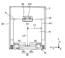
- the holding portion 4 is a rectangular plate-shaped holding plate portion 41 located on the back surface of the smartphone 5 and extending along the YZ plane, and a fixed holding portion 42 disposed on one side of the holding plate portion 41.
- the movable holding unit 43 has a holding claw 431 and is stacked on the rear surface of the holding plate unit 41, and urging means for urging the movable holding unit 43 closer to the fixed holding unit 42.
- FIG. 5 shows a state in which the smartphone 5 is not held (the state in step S13 above), and the dimensions and the positional relationship of each part are based on this state unless otherwise described.
- the fixed holding portion 42 is configured by two holding claws 421.
- the two holding claws 421 are arranged along the outer edge of the holding plate portion 41 and slidably provided, and slide along the edge of the smartphone 5 to function as an abutting portion.
- the two holding claws 421 are slidable in the ranges A1 and A2, respectively, and are spaced apart from each other in the closest state, and are positioned at the corners of the holding plate portion 41 in the most separated state. Further, in the state shown in FIG. 5, the fixed sandwiching portion 42 is disposed at substantially the same height (the same height or slightly above) as the lower end 31 of the base 3.
- a rotation axis (rotation center) O1 on which the holding portion 4 is pivotally supported by the base 3 is disposed at a Y-direction central portion of the rectangular plate-shaped base 3. Further, the rotation axis O1 is disposed closer to the moving sandwiching section 43 than the fixed sandwiching section 42 in the sandwiching direction (Z direction) by the sandwiching sections 42 and 43. Further, the rotation axis O1 is disposed at the central portion of the holding plate portion 41 in the direction (Y direction) perpendicular to the holding direction.
- one half of the dimension of the holding plate portion 41 in the orthogonal direction (that is, the distance from the rotation axis O1 to the end edge 411 of the holding plate portion 41 in the Y direction) is L1, and the rotation axis O1 in the Z direction
- the distance from the position to the fixed holding portion 42 is L2.
- the distance L2 is longer than the distance L1.
- the distance L2 is approximately half of the width of the smartphone 5 of a predetermined size (for example, 5 inches) and approximately half of the Y-direction size of the base 3. That is, the dimension in the Y direction of the base 3 is approximately equal to the width of the smartphone 5 having a predetermined dimension.
- the pivot axis O1 is positioned between the fixed holding unit 42 and the movable holding unit 43.
- the central portion in the width direction substantially agrees with the pivot axis O1.
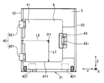
- FIG. 5 a state in which the holding unit 4 is rotated approximately 90 ° from the state shown in FIG. 5 (the state of the above step S16) is shown in FIG.
- the fixed gripping portion 42 overlaps the end edge 32 on one side in the Y direction of the base 3. Furthermore, since the distance L2 is longer than the distance L1, the end edge 411 of the holding plate portion 41 after pivoting is positioned above the fixed sandwiching portion 42 before pivoting in the Z direction.
- the distance L2 is approximately half the width of the smartphone 5
- the rotation axis O1 is disposed at the central portion of the base 3 in the Y direction
- the fixed sandwiching portion 42 overlaps the edge 32 of the base 3 Therefore, when the smartphone 5 having a predetermined size is held, the movable holding portion 43 overlaps the other end 33, and the Y-direction central portions of the smartphone 5 and the base 3 substantially coincide with each other. Further, the edges of the smartphone 5 and the base 3 on both sides in the Y direction of the predetermined size are aligned with each other.
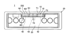
- a recessed notch 232 is formed on the upper end surface of the front panel portion 23.
- the notched portion 232 is disposed at the center in the width direction (horizontal direction) of the front panel portion 23 and is formed in a range of about 1/3 to 1/2 of the entire width of the front panel portion 23.
- the axial projection 231 is disposed in the vicinity of the lower end of the front panel portion 23, and the front panel portion 23 is configured such that the upper end portion formed with the notch portion 232 rotates around the lower end portion. .
- the depth D1 of the notch portion 232 is substantially equal to the thickness T1 of the slide portion 11 and the thickness T2 of the portion of the tilt portion 12 other than the sandwiching portions 42 and 43. Further, the depth D1 is smaller than the thickness T3 of the holding portions 42 and 43 of the tilt portion 12.
- the width W1 of the notched portion 232 is substantially equal to the width W2 of the slide portion 11 and the width W3 of the tilt portion 12. That is, the width of the slide portion 11 and the tilt portion 12 is smaller than the width of the entire front panel portion 23.
- the slide portion 11 and the tilt portion are all formed in a plate shape, and their “width” means the dimension in the width direction (Y direction). Further, when the slide portion is constituted by a pair of rail-shaped members extending along the projecting and sliding direction (X direction), the “width” of the slide portion is the opposing direction (Y direction) of the pair of rail-shaped members Means the dimensions.
- the tilt part 12 is positioned at the notch 232 and the slide part 11 and the tilt part 12 are pulled out from the apparatus body 20.
- the slide portion 11 is positioned at the notch 232.
- the smartphone 5 having a long side direction dimension larger than the width W1 of the notch 232 may be held, or a smartphone having a long side direction dimension smaller than the width W1 is held. May be
- the slide portion 11 and the tilt portion 12 are supported slidably from the front of the apparatus main body 20 and the width of the slide portion 11 is narrower than the width of the front panel portion 23.
- the separate smartphone 5 can be held while securing the area.
- the tilt portion 12 alone does not easily conceal the structure located on the back surface, but by holding the smartphone 5 in the tilt portion 12, the structure located on the back surface is obtained. It can be concealed and the design can be improved.
- the slide unit 11 and the tilt unit 12 are manually operated by the user, so that there is no need to provide an electric mechanism for the slide operation and the tilt operation, and the width of the slide unit 11 and the tilt unit 12 can be easily narrowed. be able to.
- the front panel portion 23 is configured to be rotatable and removable with respect to the apparatus main body 20, and the thickness T3 of the tilt portion 12 in the holding portions 42 and 43 is larger than the depth D1 of the notch portion 232. While making it easy to hold the smart phone 5, interference with the holding parts 42 and 43 and the front panel part 23 can be suppressed.
- the front panel portion 23 does not have to have a shape matching the holding portions 42 and 43, and the area of the front panel portion 23 can be increased.
- the tilt unit 12 includes the holding unit 4 and the base 3 and is configured to be capable of changing the direction of the held smartphone 5, so that the user can use the smartphone 5 in an appropriate direction.
- the present invention is not limited to the above-described embodiment, but includes other configurations and the like that can achieve the object of the present invention, and the following modifications and the like are also included in the present invention.
- the slide portion 11 and the tilt portion 12 are manually operated by the user, but an electric mechanism for slide operation or tilt operation may be provided.
- the notch portion 232 is formed in the front panel portion 23.
- a through hole is formed in the front panel portion, and the slide portion 11 or the tilt portion 12 is formed in the through hole. The interference may be suppressed by arranging the.
- thickness T3 of the tilt part 12 in the clamping parts 42 and 43 shall be larger than the depth D1 of the notch part 232, thickness T3 may be depth D1 or less . According to such a configuration, when the slide portion 11 is slid to pull out the tilt portion 12, there is no need to rotate or remove the front panel portion 23.
- the holding mechanism 10 includes the slide portion 11 and the tilt portion 12.
- the holding mechanism may include at least the slide portion, and the held portion may be placed on the slide portion pulled out. The held portion may be held by being held.
- maintenance apparatus 1 shall hold
- the to-be-held object which is holding object should just have a screen, for example, does not have a communication function but only a recording medium
- the reproduction apparatus may be a reproduction device that reproduces a video or the like stored in the.
- the portable device is not limited to the smartphone as in this embodiment, and may be, for example, a tablet terminal or a game device.
- the holding device is provided on the instrument panel of the vehicle in the above embodiment, the holding device may be provided on a moving object other than the vehicle, such as a ship or aircraft, or a wall or the like in a building It may be provided on furniture or the like.
Landscapes
- Engineering & Computer Science (AREA)
- Mechanical Engineering (AREA)
- Signal Processing (AREA)
- Fittings On The Vehicle Exterior For Carrying Loads, And Devices For Holding Or Mounting Articles (AREA)
- Telephone Set Structure (AREA)
- Instrument Panels (AREA)
- Casings For Electric Apparatus (AREA)
Abstract
装置本体の正面表示部の面積を確保しつつ別体の被保持物を保持することができる保持装置を提供する。保持装置(1)において、装置本体(20)の正面にフロントパネル部(23)が設けられ、スライド部(11)が装置本体(20)の正面から突没スライド自在に支持されるとともに、スライド部(11)及びチルト部(12)の幅がフロントパネル部(23)の幅よりも狭くなっている。これにより、フロントパネル部(23)の面積を確保しつつ別体のスマートフォン(5)を保持することができる。
Description
本発明は、保持装置に関する。
従来、ディスプレイがスライド移動及びチルト移動可能に構成された電子機器が提案されている(例えば、特許文献1参照)。特許文献1に記載された従来の電子機器では、不使用時にはディスプレイが本体に収納され、使用時にはディスプレイが本体の外側に向かってスライドするとともに起立し、表示画面が使用者に向けられるようになっている。
ところで、画面を有する機器として、スマートフォン等の板状のものが知られており、特許文献1に記載された電子機器において、ディスプレイに代えて、画面を有する被保持物を用いる構成が考えられる。即ち、電子機器とは別体の被保持物を保持し、この画面に適宜な映像等を表示させることにより、使用者に情報を伝達してもよい。このように別体の被保持物を用いる場合も同様に、不使用時には被保持物を保持する機構を本体に収納することが好ましく、特許文献1の電子機器と同様のスライド機構を設ければよい。
このような別体の機器を装置と連携して作動させたり、別体の機器を保持しない状態で装置自体を単独で使用したりする場合、装置本体の正面に、操作等のための表示部を設ける必要がある。このとき、装置本体の正面から保持機構を引き出そうとすると、正面表示部を設けるためのスペースが減少してしまう。
したがって、本発明の課題は、装置本体の正面表示部の面積を確保しつつ別体の被保持物を保持することができる保持装置を提供することが一例として挙げられる。
前述した課題を解決し目的を達成するために、請求項1に記載の本発明の保持装置は、被保持物を保持する保持機構と、該保持機構を取付対象に取り付ける装置本体と、を備えた保持装置であって、保持機構は、前記装置本体の正面から突没スライド自在に支持されるスライド部を備え、前記装置本体の正面には、正面表示部が設けられ、前記スライド部の幅が前記正面表示部の幅よりも狭いことを特徴としている。
以下、本発明の実施形態を説明する。本発明の実施形態に係る保持装置は、被保持物を保持する保持機構と、保持機構を取付対象に取り付ける装置本体と、を備えた保持装置である。保持機構は、装置本体の正面から突没スライド自在に支持されるスライド部を備える。装置本体の正面には、正面表示部が設けられる。スライド部の幅が正面表示部の幅よりも狭くなっている。
スライド部が装置本体の正面から突没スライド自在に支持され、スライド部の幅が正面表示部よりも狭いことで、装置本体の正面表示部の面積を確保しつつ別体の被保持物を保持することができる。
スライド部は、使用者に手動で操作される構成であることが好ましい。それにより、スライド動作のための電動機構を設ける必要がなく、スライド部の幅を容易に狭くすることができる。尚、後述のように保持機構がチルト部を備える場合、チルト部も使用者により手動で操作される構成であることが好ましい。
正面表示部には、スライド部が配置される凹状の切欠き部が形成されていることが好ましい。それにより、正面表示部とスライド部との干渉を抑制することができる。
保持機構は、起立角度を変更可能にスライド部に支持されるチルト部を備え、チルト部は、被保持物の背面に位置する矩形板状の保持板部と、保持板部から突出して被保持物を挟持する挟持部と、を有し、挟持部におけるチルト部の厚さが切欠き部の深さよりも大きく、正面表示部は、切欠き部側が装置本体から遠ざかる回動と、装置本体からの取り外しと、のうち少なくとも一方が可能に構成されていることが好ましい。それにより、挟持部の突出寸法を大きくして被保持物を挟持させやすくするとともに、挟持部が正面表示部を通過する際に、正面表示部を一時的に回動させるか又は取り外すことにより、挟持部と正面表示部との干渉を抑制することができる。従って、正面表示部を挟持部に合わせた形状とする必要がなく、正面表示部の面積を大きくすることができる。
保持機構は、保持した被保持物の向きを変更可能に構成されていることが好ましい。それにより、使用者は被保持物を適宜な向きで使用することができる。
保持機構は、被保持物として携帯機器を保持してもよいし、保持装置は、車両のインストルメントパネルに設けられてもよい。尚、ここにいう携帯機器とは、使用者によって携帯される電子機器であって、スマートフォンやタブレット端末やゲーム機器等が一例として挙げられる。
以下、本発明の実施例について図を参照して具体的に説明する。本実施例の保持装置は、車載機器であって、車両の運転席におけるインストルメントパネルに搭載されて使用される。また、本実施例の保持装置は、保持対象の被保持物として、携帯機器の一例であるスマートフォンを保持する。
本実施例の保持装置1は、図1~3に示すように、スマートフォン5の保持機構10と、インストルメントパネルに搭載される矩形箱状の装置本体20と、を備えている。
保持機構10は、装置本体20に突没自在に保持される。また、保持機構10は、装置本体20に、正面から突没スライド自在に支持されるスライド部11と、このスライド部11に軸支されてスマートフォン5を保持するチルト部12と、を備えている。保持機構10は、スマートフォン5を保持させる際には、装置本体20から図3に示されている突没方向D11における突出方向D111にスライド部11が引き出され、チルト部12が図2示されている回動方向D12における起立方向D121に立てられる。チルト部12は、後述するように基部3及び保持部4を有しており、保持部4の起立角度を変更可能なようにスライド部11に支持されている。そして、この立てられたチルト部12にスマートフォン5を保持させるように構成されている。
装置本体20は、矩形箱状の装置本体20における上壁と一対の側壁とをなす上シャーシ21と、下壁をなす下シャーシ22と、を備えている。上述の保持機構10のスライド部11は、上シャーシ21の上壁に突没スライド自在に支持されている。下シャーシ22には、矩形箱状の装置本体20における背面側の一端辺に、この装置本体20における背面壁をなす長方形状の背面基板221が立設されている。この背面基板221には、外部機器との各種接続コネクタや、スマートフォン5との間で、例えばブルートゥース(登録商標)規格等に則った短距離通信を行うためのアンテナ等が搭載されている。また、下シャーシ22の内面には、背面基板221と電気的に接続された内面基板222が取り付けられている。
また、装置本体20は、装置本体20における正面壁をなして(即ちその正面に設けられて)使用者インタフェースの役割を担う正面表示部としての長方形板状の脱着可能なフロントパネル部23と、このフロントパネル部23を着脱自在、かつ、回動自在に保持するパネル部24と、を備えている。パネル部24は、上シャーシ21及び下シャーシ22に固定される。このパネル部24は、上シャーシ21に支持される保持機構10と干渉しないように切欠きが設けられた形状に形成されている。フロントパネル部23の長手方向の両端には、回動軸をなす一対の軸突起231が設けられ、これら一対の軸突起231が、パネル部24における一対の保持アーム241に、着脱自在かつ回動自在に保持される。即ち、フロントパネル部23は、装置本体20に対し、回動操作及び取り外し操作が可能となっている。
本実施例の保持装置1では、上シャーシ21に支持される保持機構10と、パネル部24と、のそれぞれが、下シャーシ22の内面基板222に、ケーブル223で電気的に接続されている。本実施例では、図2に示されているように保持されたスマートフォン5に対するタッチ操作や、フロントパネル部23に対するボタン操作により、例えばスマートフォン5の画面上への地図情報の表示や、車載オーディオ機器からの音楽の再生等を行うことができる。また、保持したスマートフォン5に対する充電を、保持機構10と内面基板222とを繋ぐケーブル223と、スマートフォン5から延伸して保持機構10に接続した充電ケーブルと、を介して行うこともできる。
以上に説明した保持装置1は、次のような手順によってスマートフォン5を保持させる。
図4は、図1~図3に示されている保持装置にスマートフォンを保持させるための一例の手順を示す模式図である。尚、この図4では、図を見易くするために、装置本体20については、上シャーシ21のみが示されている。以下に説明する手順は、使用者の手作業(手動)によって行われる。
まず、ステップS11及びステップS12において、装置本体20から突出方向D111に保持機構10が引き出される。このとき、本実施例では、フロントパネル部23は、保持機構10の動きの邪魔とならないように、図3に示されている軸突起231を回動中心として回動されて前方に倒されるか、パネル部24から取り外される。即ち、フロントパネル部23は、後述する切欠き部232側が装置本体20から遠ざかる回動と、装置本体20からの取り外しと、の両方が可能となっている。またこのとき、保持機構10において、後述する保持爪421、431が引き出し方向に対向して(即ち並んで)いる。即ち、保持機構10の挟持方向と、スライド部11の突没スライド方向と、が一致した状態で保持機構10が装置本体20に収納されるようになっている。
続くステップS13では、保持機構10において、チルト部12がスライド部11に対して起立方向D121に立てられる。このとき、チルト部12は、スライド部11に軸支された基部3と、基部3によって回動自在に支持される保持部4と、を備え、保持部4において、計3本の保持爪421、431によってチャッキング機構46が構成されている。本実施例では、このステップS13でチルト部12が立てられた状態では、チャッキング機構46は、1本の保持爪431が上部側に位置し、2本の保持爪421が下部側に位置する姿勢となっている。また、チャッキング機構46では、上部側となる1本の保持爪431が、下部側となる2本の保持爪421に向かってバネ付勢されている。
ステップS14では、このチャッキング機構46におけるバネ付勢に抗して上部側の保持爪431が引上げ方向D131に引き上げられる。
そして、ステップS15において、上記のように引き上げられた上部側の保持爪431と、下部側の保持爪421と、の間に、スマートフォン5が、その長手方向が水平方向を向く横向きで配置される。使用者が上部側の保持爪431を離すと、上記のバネ付勢により上部側の保持爪431が下降方向D132に動く。これにより、上部側の保持爪431と、下部側の保持爪421と、でスマートフォン5が挟持される。
ここで、本実施例では、チルト部12において、チャッキング機構46を有する保持部4が、スマートフォン5の画面の面直方向に沿った回動軸O1を中心とした回動方向D14に回動自在に取り付けられている。上記のようにステップS15の段階では、スマートフォン5は横向き(その長手方向が水平方向を向いた状態)で保持されている。使用者が、このスマートフォン5を縦向き(その長手方向が上下方向を向いた状態)にして表示画面を見たいと考えた場合、次のステップS16によって、スマートフォン5を縦向きとすることができる。即ち、ステップS16では、スマートフォン5ごと、チャッキング機構46が、回動軸O1を中心として図中の時計回りに90°回動される。この回動によりスマートフォン5が縦向きとなる。また、この後、使用者が、スマートフォン5を横向きにして表示画面を見たいと考えた場合には、チャッキング機構46が図中の反時計回りに90°戻されて、スマートフォン5が横向きとされる。
また、本実施例では、使用者は、保持機構10を引き出した後の任意のタイミングでフロントパネル部23を戻す。その結果、スマートフォン5の保持を行なった後の外観が、例えば図2示されているような外観となる。スマートフォン5が外されて保持機構10が装置本体20に収納される際には、図4に示されている手順とは逆の手順によって、保持機構10の収納が行われる。
ここで、保持部4の詳細な形状について説明する。以下では、車両の前後方向(進行方向)をX方向とし、車幅方向(左右方向)をY方向とし、上下方向をZ方向とし、保持装置1は、スマートフォン5をX方向後方側に向けて(即ち画面がYZ平面に沿うように)保持するものとする。また、長方形状のスマートフォン5の短辺方向を幅方向とする。
保持部4は、図5に示すように、スマートフォン5の背面に位置してYZ平面に沿って延びる矩形板状の保持板部41と、保持板部41の一辺に配置された固定挟持部42と、保持板部41の背面に重ねられるとともに保持爪431を有する移動挟持部43と、移動挟持部43を固定挟持部42に近づけるように付勢する付勢手段と、を有する。尚、図5は、スマートフォン5を保持していない状態(上記のステップS13の状態)を示しており、各部の寸法および位置関係については、特に説明がない限りこの状態を基準とする。
固定挟持部42は、2つの保持爪421によって構成されている。2つの保持爪421は、保持板部41の外縁に沿って並ぶとともにスライド自在に設けられており、スマートフォン5の端縁に沿ってスライドして当接部として機能する。また、2つの保持爪421は、それぞれ範囲A1、A2においてスライド自在となっており、最接近状態において互いに所定の間隔をあけるとともに、最離隔状態において、保持板部41の隅部に位置する。また、固定挟持部42は、図5に示す状態において、基部3の下端31と略同一高さ(同程度の高さ又はやや上方)に配置されている。
保持部4が基部3によって軸支される回動軸(回動中心)O1は、矩形板状の基部3のY方向中央部に配置されている。また、回動軸O1は、挟持部42、43による挟持方向(Z方向)において、固定挟持部42よりも移動挟持部43の近くに配置されている。また、回動軸O1は、挟持方向との直交方向(Y方向)において、保持板部41の中央部に配置される。ここで、上記の直交方向における保持板部41の寸法の半分(即ち、回動軸O1からY方向における保持板部41の端縁411までの距離)をL1とし、Z方向における回動軸O1から固定挟持部42までの距離をL2とする。本実施例では、距離L2が距離L1よりも長い。また、距離L2は、所定寸法(例えば5インチ)のスマートフォン5の幅の略半分であるとともに、基部3のY方向寸法の略半分である。即ち、基部3のY方向寸法は、所定寸法のスマートフォン5の幅と略等しい。
このような保持部4によって所定寸法のスマートフォン5を挟持するために移動挟持部43を移動させると、固定挟持部42と移動挟持部43との中間に回動軸O1が位置し、スマートフォン5の幅方向中央部と、回動軸O1と、が略一致する。
ここで、図5に示す状態から、保持部4を略90°回動させた様子(上記のステップS16の状態)を図6に示す。このとき、固定挟持部42は、基部3のY方向一方側の端縁32に重なる。さらに、距離L2が距離L1よりも長いことから、回動後の保持板部41の端縁411は、回動前の固定挟持部42よりもZ方向において上方に位置する。
図6に示す状態において、距離L2がスマートフォン5の幅の略半分であり、回動軸O1がY方向において基部3の中央部に配置され、固定挟持部42が基部3の端縁32に重なっていることから、所定寸法のスマートフォン5を挟持した際、移動挟持部43が他方側の端縁33に重なり、スマートフォン5及び基部3のY方向中央部同士が略一致する。また、所定寸法のスマートフォン5及び基部3のY方向両側の端縁同士が揃う。
次に、フロントパネル部23及び保持機構10の詳細な形状及び寸法について、図1、2に基づいて説明する。
フロントパネル部23の上端面には、凹状の切欠き部232が形成されている。切欠き部232は、フロントパネル部23の幅方向(水平方向)中央部に配置され、フロントパネル部23の幅全体のうち1/3~1/2程度の範囲に形成されている。また、軸突起231はフロントパネル部23の下端近傍に配置されており、フロントパネル部23は、下端部を中心として、切欠き部232が形成された上端部が回動するようになっている。
切欠き部232の深さD1は、スライド部11の厚さT1、及び、チルト部12のうち挟持部42、43以外の部分の厚さT2と略等しい。また、深さD1は、チルト部12のうち挟持部42、43における厚さT3よりも小さい。切欠き部232の幅W1は、スライド部11の幅W2、及び、チルト部12の幅W3と略等しい。即ち、スライド部11及びチルト部12の幅が、フロントパネル部23全体の幅よりも狭くなっている。尚、本実施例では、スライド部11及びチルト部はいずれも全体が板状に形成されており、これらの「幅」とは、幅方向(Y方向)寸法を意味する。また、スライド部が突没スライド方向(X方向)に沿って延びる一対のレール状部材によって構成される場合には、スライド部の「幅」は、一対のレール状部材の対向方向(Y方向)寸法を意味する。
スライド部11及びチルト部12が装置本体20に収納された際、図1に示すように、チルト部12が切欠き部232に位置付けられ、スライド部11及びチルト部12が装置本体20から引き出されてスマートフォン5を保持する際、図2に示すように、スライド部11が切欠き部232に位置付けられる。尚、図2に示すように、切欠き部232の幅W1よりも大きい長辺方向寸法を有するスマートフォン5を保持してもよいし、幅W1よりも小さい長辺方向寸法を有するスマートフォンを保持してもよい。
上記の構成により、スライド部11及びチルト部12が装置本体20の正面から突没スライド自在に支持され、スライド部11の幅がフロントパネル部23の幅よりも狭いことで、フロントパネル部23の面積を確保しつつ別体のスマートフォン5を保持することができる。さらに、チルト部12の幅を狭くすると、チルト部12単体では、その背面に位置する構造物を隠しにくくなるものの、チルト部12にスマートフォン5を保持させることにより、その背面に位置する構造物を隠すことができ、意匠性を向上させることができる。
スライド部11及びチルト部12は、使用者により手動で操作されることで、スライド動作およびチルト動作のための電動機構を設ける必要がなく、スライド部11及びチルト部12の幅を容易に狭くすることができる。
フロントパネル部23に凹状の切欠き部232が形成されていることで、フロントパネル部23とスライド部11及びチルト部12との干渉を抑制することができる。
フロントパネル部23が、装置本体20に対して回動および取り外し可能に構成されるとともに、挟持部42、43におけるチルト部12の厚さT3が切欠き部232の深さD1よりも大きいことで、スマートフォン5を挟持させやすくするとともに、挟持部42、43とフロントパネル部23との干渉を抑制することができる。フロントパネル部23を挟持部42、43に合わせた形状とする必要がなく、フロントパネル部23の面積を大きくすることができる。
チルト部12が、保持部4と基部3とを備え、保持したスマートフォン5の向きを変更可能に構成されていることで、使用者はスマートフォン5を適宜な向きで使用することができる。
なお、本発明は、前記実施例に限定されるものではなく、本発明の目的が達成できる他の構成等を含み、以下に示すような変形等も本発明に含まれる。
例えば、前記実施例では、スライド部11及びチルト部12が使用者により手動で操作されるものとしたが、スライド動作やチルト動作のための電動機構が設けられてもよい。
また、前記実施例では、フロントパネル部23に凹状の切欠き部232が形成されるものとしたが、フロントパネル部に貫通孔が形成されるとともに、この貫通孔にスライド部11又はチルト部12が配置されることにより、干渉が抑制されていてもよい。
また、前記実施例では、挟持部42、43におけるチルト部12の厚さT3が切欠き部232の深さD1よりも大きいものとしたが、厚さT3が深さD1以下であってもよい。このような構成によれば、スライド部11をスライドさせてチルト部12を引き出す際に、フロントパネル部23を回動させたり取り外したりする必要がない。
また、前記実施例では、チルト部12が保持したスマートフォン5の向きを変更可能に構成されているものとしたが、保持装置は、スマートフォンを一定の向きで保持して使用するものであってもよい。
また、前記実施例では、保持機構10がスライド部11及びチルト部12を備えるものとしたが、保持機構は少なくともスライド部を備えていればよく、引き出されたスライド部に被保持部が載置されることにより、被保持部が保持される構成としてもよい。
また、前記実施例では、保持装置1がスマートフォンを保持するものとしたが、保持対象である被保持物は、画面を有するものであればよく、例えば通信機能を有しておらず単に記録媒体に記憶された映像等を再生する再生機器であってもよい。また、被保持物が携帯機器である場合、その携帯機器は、本実施例のようにスマートフォンに限るものでもなく、例えばタブレット端末やゲーム機器等であってもよい。
また、前記実施例では、保持装置が車両のインストルメントパネルに設けられるものとしたが、保持装置は、船舶や航空機等、車両以外の移動体に設けられてもよいし、建物内の壁や家具等に設けられてもよい。
その他、本発明を実施するための最良の構成、方法などは、以上の記載で開示されているが、本発明は、これに限定されるものではない。すなわち、本発明は、主に特定の実施形態に関して特に図示され、且つ、説明されているが、本発明の技術的思想および目的の範囲から逸脱することなく、以上述べた実施例に対し、形状、材質、数量、その他の詳細な構成において、当業者が様々な変形を加えることができるものである。従って、上記に開示した形状、材質などを限定した記載は、本発明の理解を容易にするために例示的に記載したものであり、本発明を限定するものではないから、それらの形状、材質などの限定の一部、もしくは全部の限定を外した部材の名称での記載は、本発明に含まれるものである。
1 保持装置
10 保持機構
11 スライド部
12 チルト部
20 装置本体
23 フロントパネル部(正面表示部)
232 凹部
3 基部
4 保持部
41 保持板部
42 固定挟持部
43 移動挟持部
5 スマートフォン(被保持物)
10 保持機構
11 スライド部
12 チルト部
20 装置本体
23 フロントパネル部(正面表示部)
232 凹部
3 基部
4 保持部
41 保持板部
42 固定挟持部
43 移動挟持部
5 スマートフォン(被保持物)
Claims (7)
- 被保持物を保持する保持機構と、該保持機構を取付対象に取り付ける装置本体と、を備えた保持装置であって、
前記保持機構は、前記装置本体の正面から突没スライド自在に支持されるスライド部を備え、
前記装置本体の正面には、正面表示部が設けられ、
前記スライド部の幅が前記正面表示部の幅よりも狭いことを特徴とする保持装置。 - 前記スライド部は、使用者に手動で操作される構成であることを特徴とする請求項1に記載の保持装置。
- 前記正面表示部には、前記スライド部が配置される凹状の切欠き部が形成されていることを特徴とする請求項1に記載の保持装置。
- 前記保持機構は、起立角度を変更可能に前記スライド部に支持されるチルト部を備え、
前記チルト部は、前記被保持物の背面に位置する矩形板状の保持板部と、該保持板部から突出して前記被保持物を挟持する挟持部と、を有し、
前記挟持部における前記チルト部の厚さが前記切欠き部の深さよりも大きく、
前記正面表示部は、前記切欠き部側が前記装置本体から遠ざかる回動と、前記装置本体からの取り外しと、のうち少なくとも一方が可能に構成されていることを特徴とする請求項3に記載の保持装置。 - 前記保持機構は、保持した前記被保持物の向きを変更可能に構成されていることを特徴とする請求項1に記載の保持装置。
- 前記保持機構は、前記被保持物として携帯機器を保持することを特徴とする請求項1に記載の保持装置。
- 車両のインストルメントパネルに設けられることを特徴とする請求項1に記載の保持装置。
Priority Applications (1)
| Application Number | Priority Date | Filing Date | Title |
|---|---|---|---|
| JP2019525450A JPWO2018235672A1 (ja) | 2017-06-19 | 2018-06-12 | 保持装置 |
Applications Claiming Priority (2)
| Application Number | Priority Date | Filing Date | Title |
|---|---|---|---|
| JP2017-119341 | 2017-06-19 | ||
| JP2017119341 | 2017-06-19 |
Publications (1)
| Publication Number | Publication Date |
|---|---|
| WO2018235672A1 true WO2018235672A1 (ja) | 2018-12-27 |
Family
ID=64735644
Family Applications (1)
| Application Number | Title | Priority Date | Filing Date |
|---|---|---|---|
| PCT/JP2018/022387 Ceased WO2018235672A1 (ja) | 2017-06-19 | 2018-06-12 | 保持装置 |
Country Status (2)
| Country | Link |
|---|---|
| JP (4) | JPWO2018235672A1 (ja) |
| WO (1) | WO2018235672A1 (ja) |
Citations (5)
| Publication number | Priority date | Publication date | Assignee | Title |
|---|---|---|---|---|
| JP2003095027A (ja) * | 2001-09-25 | 2003-04-03 | Clarion Co Ltd | 車載用音響機器の盗難防止装置 |
| JP2006306398A (ja) * | 2006-07-10 | 2006-11-09 | Alpine Electronics Inc | 車載用電子機器 |
| JP2012015574A (ja) * | 2010-06-29 | 2012-01-19 | Panasonic Corp | 電子機器 |
| WO2012067029A1 (ja) * | 2010-11-18 | 2012-05-24 | 株式会社ニフコ | 電子機器保持具 |
| US20130016850A1 (en) * | 2011-07-14 | 2013-01-17 | Byungmu Huh | Stationary apparatus for portable electronic device |
-
2018
- 2018-06-12 WO PCT/JP2018/022387 patent/WO2018235672A1/ja not_active Ceased
- 2018-06-12 JP JP2019525450A patent/JPWO2018235672A1/ja active Pending
-
2021
- 2021-04-27 JP JP2021074721A patent/JP2021141588A/ja active Pending
-
2023
- 2023-01-17 JP JP2023005024A patent/JP2023061930A/ja active Pending
-
2024
- 2024-11-21 JP JP2024202852A patent/JP2025024175A/ja active Pending
Patent Citations (5)
| Publication number | Priority date | Publication date | Assignee | Title |
|---|---|---|---|---|
| JP2003095027A (ja) * | 2001-09-25 | 2003-04-03 | Clarion Co Ltd | 車載用音響機器の盗難防止装置 |
| JP2006306398A (ja) * | 2006-07-10 | 2006-11-09 | Alpine Electronics Inc | 車載用電子機器 |
| JP2012015574A (ja) * | 2010-06-29 | 2012-01-19 | Panasonic Corp | 電子機器 |
| WO2012067029A1 (ja) * | 2010-11-18 | 2012-05-24 | 株式会社ニフコ | 電子機器保持具 |
| US20130016850A1 (en) * | 2011-07-14 | 2013-01-17 | Byungmu Huh | Stationary apparatus for portable electronic device |
Also Published As
| Publication number | Publication date |
|---|---|
| JP2023061930A (ja) | 2023-05-02 |
| JP2021141588A (ja) | 2021-09-16 |
| JPWO2018235672A1 (ja) | 2020-04-16 |
| JP2025024175A (ja) | 2025-02-19 |
Similar Documents
| Publication | Publication Date | Title |
|---|---|---|
| JP2024109974A (ja) | 保持装置 | |
| JP5609763B2 (ja) | コネクタ構造及び電子機器 | |
| CN103518365B (zh) | 电子设备 | |
| CN103262566A (zh) | 用于视听重现设备的支撑支架 | |
| JP2014107714A (ja) | 携帯端末装置 | |
| WO2018235672A1 (ja) | 保持装置 | |
| US20210088176A1 (en) | Ptz assembly and a clamping mechanism thereof | |
| JP2025010205A (ja) | 保持装置 | |
| JP6969906B2 (ja) | 保持装置 | |
| JP2022023927A (ja) | 保持装置 | |
| JP7025519B2 (ja) | 保持装置 | |
| JP2018202974A (ja) | 保持装置 | |
| CN216383486U (zh) | 移动设备固定支架 | |
| JP2026020199A (ja) | 保持装置 | |
| JPWO2019142756A1 (ja) | スタンド装置 | |
| JP2019007535A (ja) | 保持装置 | |
| JP2006135830A (ja) | 携帯端末 | |
| JP3162834U (ja) | 携帯電話スタンド | |
| JP2019009590A (ja) | 保持装置 |
Legal Events
| Date | Code | Title | Description |
|---|---|---|---|
| 121 | Ep: the epo has been informed by wipo that ep was designated in this application |
Ref document number: 18820422 Country of ref document: EP Kind code of ref document: A1 |
|
| ENP | Entry into the national phase |
Ref document number: 2019525450 Country of ref document: JP Kind code of ref document: A |
|
| NENP | Non-entry into the national phase |
Ref country code: DE |
|
| 122 | Ep: pct application non-entry in european phase |
Ref document number: 18820422 Country of ref document: EP Kind code of ref document: A1 |