WO2018235277A1 - 光ファイバ走査装置および内視鏡 - Google Patents
光ファイバ走査装置および内視鏡 Download PDFInfo
- Publication number
- WO2018235277A1 WO2018235277A1 PCT/JP2017/023250 JP2017023250W WO2018235277A1 WO 2018235277 A1 WO2018235277 A1 WO 2018235277A1 JP 2017023250 W JP2017023250 W JP 2017023250W WO 2018235277 A1 WO2018235277 A1 WO 2018235277A1
- Authority
- WO
- WIPO (PCT)
- Prior art keywords
- optical fiber
- coil
- opposing
- scanning device
- magnet
- Prior art date
- Legal status (The legal status is an assumption and is not a legal conclusion. Google has not performed a legal analysis and makes no representation as to the accuracy of the status listed.)
- Ceased
Links
Images




Classifications
-
- A—HUMAN NECESSITIES
- A61—MEDICAL OR VETERINARY SCIENCE; HYGIENE
- A61B—DIAGNOSIS; SURGERY; IDENTIFICATION
- A61B1/00—Instruments for performing medical examinations of the interior of cavities or tubes of the body by visual or photographical inspection, e.g. endoscopes; Illuminating arrangements therefor
-
- G—PHYSICS
- G02—OPTICS
- G02B—OPTICAL ELEMENTS, SYSTEMS OR APPARATUS
- G02B23/00—Telescopes, e.g. binoculars; Periscopes; Instruments for viewing the inside of hollow bodies; Viewfinders; Optical aiming or sighting devices
- G02B23/24—Instruments or systems for viewing the inside of hollow bodies, e.g. fibrescopes
- G02B23/26—Instruments or systems for viewing the inside of hollow bodies, e.g. fibrescopes using light guides
-
- G—PHYSICS
- G02—OPTICS
- G02B—OPTICAL ELEMENTS, SYSTEMS OR APPARATUS
- G02B26/00—Optical devices or arrangements for the control of light using movable or deformable optical elements
- G02B26/08—Optical devices or arrangements for the control of light using movable or deformable optical elements for controlling the direction of light
- G02B26/10—Scanning systems
Definitions
- the present invention comprises an optical fiber scanning device having an optical fiber whose tip vibrates in a first direction and a second direction orthogonal to the first direction, and comprising the optical fiber scanning device at the tip of the insertion portion Related to endoscopes.
- An image pickup apparatus using an image pickup element such as a CCD or a CMOS image sensor simultaneously receives reflected light from an object by an image pickup element unit including a large number of light receiving elements arranged in a matrix, and acquires an object image.
- an image pickup element such as a CCD or a CMOS image sensor
- the light scanning type imaging device while scanning and irradiating a subject with a light spot, the reflected light is sequentially received, and a subject image is created based on the received light data.
- the optical fiber scanning device guides the light from the light source, and scans and irradiates the light spot by two-dimensionally scanning the tip of the optical fiber held at one end at a fixed end by vibrating. Is done.
- the optical fiber vibrates when a magnetic field generated by a drive coil is applied to a permanent magnet disposed in the optical fiber.
- a magnetic field generated by a drive coil is applied to a permanent magnet disposed in the optical fiber.
- magnetic fields are applied in two orthogonal directions.
- Japanese Patent Application Laid-Open No. 2015-211761 discloses an optical fiber scanning device in which a magnetic field is applied in two orthogonal directions by two pairs of opposing coils.
- the optical fiber can be scanned more efficiently by arranging two pairs of opposing coils on the N pole side and the S pole side of the magnet, that is, using four pairs of opposing coils. Is described. Furthermore, it is described that higher order resonant frequencies allow for higher resonant frequency scanning.
- Japanese Patent Laid-Open Publication No. 2010-9035 discloses an optical fiber scanning device including a set of multilayer thin film coils which generate magnetic fields in orthogonal orthogonal directions disposed on the cylindrical surface of a cylindrical tube. .
- the coil for the X direction scan has the same configuration as the coil for the Y direction scan.
- An embodiment of the present invention aims to provide an endoscope equipped with an optical fiber scanning device that performs efficient scan irradiation, and an optical fiber scanning device that performs efficient scan irradiation.
- the optical fiber scanning device emits an illumination light from the tip, is an optical fiber cantilevered at a fixed end, and is magnetized in the direction of the optical axis of the optical fiber and disposed in the optical fiber
- a plurality of opposing coils for applying a magnetic field to the magnet the plurality of opposing coils applying a first magnetic field in a first direction orthogonal to the optical axis to the magnet
- a pair of second opposing coils for applying a second magnetic field in the first direction and in a second direction orthogonal to the optical axis to the magnet.
- the plurality of opposing pairs such that the first opposing coil applies the first magnetic field to the front of the magnet and the second opposing coil applies the second magnetic field to the rear of the magnet
- a coil is arranged.
- the endoscope of another embodiment comprises an optical fiber scanning device at the distal end of the insertion portion, and the optical fiber scanning device emits illumination light from the distal end and is cantilevered at the fixed end.
- a pair of first opposing coils for applying to the magnet a first magnetic field in a first direction orthogonal to the optical axis; and a second orthogonal coil orthogonal to the first direction and the optical axis
- a pair of second opposing coils for applying a second magnetic field in a direction to the magnet, the first opposing coil applying the first magnetic field to the front of the magnets, and The plurality of opposing coils so that the second magnetic field is applied to the back of the magnet.
- Opposing coils are disposed.
- an optical fiber scanning device that performs efficient scan irradiation
- an endoscope that provides an endoscope that performs efficient scan irradiation
- optical fiber scanning device 1 of the present embodiment will be described with reference to the drawings.
- the imaging system 90 including the optical fiber scanning device 1 includes the optical fiber scanning device 1, an optical fiber 19 for light reception, a light source unit 91, a detection unit 92, and a drive signal generation unit 93. , A control unit 94, a display unit 95, and an input unit 96.
- the optical fiber scanning device 1 includes an optical fiber 10 for illumination, a magnet 20 disposed in the optical fiber 10, and a plurality of pairs of opposed coils 30, 40.
- the plurality of sets of opposed coils consist of a set of first opposed coils 30 and a set of second opposed coils 40.
- the drive signal generation unit 93 generates and outputs a drive signal for driving the first opposing coil 30 and the second opposing coil 40.
- One set of first opposing coils 30 applies to the magnet 20 a first magnetic field M1 in a first direction (Y-axis direction) orthogonal to the optical axis O.
- One pair of second opposing coils 40 applies a second magnetic field M2 to the magnet 20 in a first direction (Y-axis direction) and a second direction (X-axis direction) orthogonal to the optical axis O.
- the optical fiber 10 is inserted into a through hole of a fiber holding member (ferrule) made of, for example, nickel, and from the fixed end 12 to the tip 11 is a vibrating portion that protrudes from the through hole. That is, in the optical fiber 10, the vibrating portion from the fixed end 12 to the tip 11 vibrates in a first direction (Y-axis direction) and a second direction (X-axis direction) orthogonal to the first direction. .
- the first direction and the second direction are orthogonal to the optical axis direction (Z-axis direction). Needless to say, the first direction may be the X-axis direction, and the second direction may be the Y-axis direction.
- the light source unit 91 combines lights from three laser light sources that emit CW (continuous wave) laser lights of three primary colors of red, green and blue, for example, and emits the combined light as white light.
- a laser light source for example, a DPSS laser (semiconductor-excited solid state laser) or a laser diode can be used.
- the configuration of the light source unit 91 is not limited to this, and one laser light source may be used, or a plurality of other light sources may be used.
- the vibrating portion of the optical fiber 10 cantilevered at the fixed end 12 is oscillated by the first magnetic field M1 and the second magnetic field M2 applied to the magnet 20, and is emitted from the tip 11 of the optical fiber 10
- the spot illumination light is two-dimensionally scanned to illuminate an object to be observed.
- the reflected light of the observed object illuminated by the illumination light enters the detection unit 92 through the optical fiber 19 for detection.
- the detection unit 92 separates the reflected light into spectral components and converts the light into electrical signals by photodiodes.
- the control unit 94 synchronously controls the light source unit 91, the detection unit 92, and the drive signal generation unit 93, processes the electric signal output from the detection unit 92, synthesizes an image, and displays it on the display unit 95.
- the user sets the imaging system 90 such as the scanning speed and the brightness of the display image via the input unit 96.
- the light source unit 91, the detection unit 92, the drive signal generation unit 93, and the control unit 94 may be housed in the same housing, or may be housed in separate housings.
- the optical fiber 10 guides the light from the light source unit 91 and emits illumination light from the tip 11 which is a free end.
- the optical fiber scanning device 1 may include an illumination optical system configured to condense illumination light emitted by the optical fiber 10 on the surface of the object to be observed.
- a condensing optical system may be disposed at the tip of the detection optical fiber 19.
- the optical fiber scanning device 1 has a plurality of optical fibers 19 in order to obtain a sufficient amount of detected light.
- the coil 31 and the coil 32 are disposed to face each other. Further, in the second opposing coil 40, the coil 41 and the coil 42 are disposed so as to face each other.
- coil 31 etc. are spirals in which a conductor pattern disposed on a base such as a silicon substrate is wound in a plane. It is a planar coil.
- the coil 31 or the like may be a multilayer planar coil in which two or more layers of spiral coils are connected via an insulating layer.
- the flexible base on which the coil 31 and the like are disposed may be deformed into a tubular shape.
- the coil 31 or the like may have a magnetic core made of a soft magnetic material.
- the tube type magnet 20 has a through hole at the center, and the optical fiber 10 is inserted into the through hole and fixed by an adhesive (not shown).
- the elongated magnet 20 is magnetized in the direction of the optical axis O of the optical fiber 10.
- the magnet 20 is magnetized such that the front (the tip side of the optical fiber 10) is N pole and the rear (the fixed end side of the optical fiber 10) is S pole.
- the first opposing coil 30 applies a first magnetic field M 1 to the front of the magnet 20.
- the second opposing coil 40 applies a second magnetic field M 2 to the rear of the magnet 20.
- the first opposing coil 30 is disposed closer to the tip end of the optical fiber 10 than the second opposing coil 40, and the distance between the centers of the two is substantially the same as the length of the magnet 20.
- the magnet may be configured of a first magnet to which the first magnetic field M1 is applied and a second magnet to which the second magnetic field M2 is applied.
- the first opposing coil 30 is disposed on the rear end side (fixed end side) of the second opposing coil 40, and the first opposing coil 30 is disposed on the rear side of the magnet 20 in the first magnetic field M1.
- the second opposing coil 40 may apply a second magnetic field M 2 to the front of the magnet 20.
- the combination of the vibration in the first direction and the vibration in the second direction causes the tip 11 of the optical fiber 10 to move in a predetermined scanning pattern in the XY plane.
- the combination of the vibration pattern in the first direction (Y-axis scan) and the vibration pattern in the second direction (X-axis scan) makes the scan system be a spiral scan, raster scan, Lissajous scan, or the like.
- FIG. 5 shows an example in which an image signal is acquired at the time of vibration to the positive side in the first direction (Y-axis direction), the image signal may be acquired at the time of vibration on the negative side or at both sides.
- the display unit 95 is a horizontally long screen, the amplitude AX in the second direction (X-axis direction) is larger than the amplitude AY in the first direction (Y-axis direction).
- the second magnetic field M2 generated by the second opposing coil 40 must be larger than the first magnetic field M1 generated by the first opposing coil 30.
- the first facing distance DY which is the distance between the coil 31 and the coil 32 of the first facing coil 30, and the distance between the coil 41 of the second facing coil 40 and the coil 42
- the facing distance DX of 2 is different. That is, the second facing distance DX is shorter than the first facing distance DY.
- the magnetic field strength M at the center of the opposing coil, ie, at the magnet position, is (1 / D 2 ) for the opposing distance D.
- the second opposing distance DX may be 80% of the first opposing distance DY.
- the second magnetic field M2 is 1.56 times the first magnetic field M1.
- the optical fiber scanning device 1 can easily generate the second magnetic field M2 larger than the first magnetic field M1, efficient scan irradiation can be performed.
- two sets of opposing coils are generated at the front and rear of the magnet 20, that is, the opposing coil generating the magnetic field in the first direction and the magnetic field in the second direction. Opposing coils were disposed.
- the coil 31 or the like which is a spiral flat coil, increases the magnetic field strength generated in proportion to the number of turns (the number of turns).
- the number of turns In the case of a flat coil, in the case of the same pitch (conductor width / space width), increasing the number of turns increases the size of the coil, that is, the size in plan view (outside size / area). For this reason, in a conventional fiber scanning device in which two pairs of opposing coils are disposed at the same position with respect to the direction of the optical axis, the size of the two pairs of opposing coils disposed orthogonally is limited by the opposing distance It had been.
- the optical fiber scanning device 1 only the first opposing coil 30 is provided with a coil for applying a magnetic field to the front of the magnet 20. Also, only the second opposing coil 40 is provided with a coil for applying a magnetic field to the rear of the magnet 20. That is, only one set of opposing coils is disposed at each position.
- each of the first opposing coil 30 and the second opposing coil 40 may have a plurality of multilayer coils.
- the first opposing coil 30 and the second opposing coil 40 may be a composite opposing coil composed of a plurality of pairs of opposing coils each applying a magnetic field in the same direction.
- the facing distance DX of the second facing coil 40 may be smaller than the width LY of the first facing coil 30, and the facing distance DY of the first facing coil 30 is , And may be smaller than the width LX of the second opposing coil 40.
- the first opposing coil 30 and the second opposing coil 40 partially cross each other. That is, the size of the two pairs of opposing coils 30 and 40 disposed orthogonally is not limited by the opposing distance.
- the optical fiber scanning device 1 can set the number of turns of the first opposing coil 30 and the number of turns of the second opposing coil 40 to be different. Since the number of turns of the second opposing coil 40 (coils 41 and 42) can be larger than the number of turns of the first opposing coil 30 (coils 31 and 32), the optical fiber scanning device 1 performs efficient scanning irradiation. It can be carried out.
- the optical fiber 10 vibrates primarily in the first direction (Y-axis direction).
- the optical fiber 10 vibrates in a third order in the second direction (X-axis direction).
- the first corresponding coil 30 (31, 32) applies a magnetic field to the front of the magnet 20.
- the second opposing coil 40 (41, 42) applies a magnetic field to the rear of the magnet 20.
- the optical fiber 10 that vibrates in a third order has, for example, the vibration node at three positions on the tip end side of the fixed end 12 and the position of the magnet 20 and the position of the first opposing coil 30 in plan view. That is, there is a point which does not vibrate. And, between the nodes of vibration, there is a vibration antinode with a large amplitude.
- the amplitude A1X at the antinode of the oscillation closest to the fixed end 12 is, for example, 0.2 AX as compared to the amplitude AX of the tip 11, which is very small. Therefore, even if the second facing distance DX of the second facing coil 40 is reduced, there is no possibility that the oscillated optical fiber comes in contact with the coil.
- the resonance frequency FRX in the second direction in which the third vibration occurs is, for example, 20 times the resonance frequency FRY in the first direction in which the first vibration vibrates, high-speed scanning is easy.
- the optical fiber scanning device 1 can perform raster scanning particularly efficiently.
- the optical fiber 10 may have a second-order vibration in which the second direction vibrates in a high-order vibration that facilitates high-speed scanning and easily increases the amplitude than the first direction in which the first-order vibration occurs. Furthermore, the optical fiber 10 may perform secondary vibration in the first direction and third vibration in the second direction, and of course may perform primary vibration in the first direction and the second direction. .
- optical fiber scanning device 1A according to the modification of the first embodiment is similar to the optical fiber scanning device 1 and has the same effect.
- the size of the first opposing coil 30 (31, 32) and the size of the second opposing coil 40A (41A, 42A) are different.
- the first opposing coil 30 (31, 32) is a three-turn coil.
- the second opposing coil 40A (41A, 42A) shown in FIG. 9B is a four-turn coil.
- the outer dimension LX of the second opposing coil 40A (41A, 42A) is about 20% larger than the outer dimension LY of the first opposing coil 30 (31, 32).
- the coils 31, 32, 41A and 42A have a square outer shape, they have the same outer size in the vertical direction and the outer size in the horizontal direction, LY or LX. However, it goes without saying that the coils 31, 32, 41A, 42A may have a rectangular outer shape.
- the two pairs of opposing coils 30 and 40A disposed orthogonal to each other have different arrangement positions, so their sizes ) Is not limited by the opposing distance.
- the second opposing coil 40A (41A, 42A) that generates a larger magnetic field is a large coil having a larger number of turns than the first opposing coil 30 (31, 32). More efficient scan irradiation can be performed than the fiber scanning device 1.
- the drive signal generation unit 93 may set the current value of the drive signal to flow to the first opposing coil 30 and the current value of the drive signal to flow to the second opposing coil 40 so as to be different.
- the upper limit of the current value of the drive signal allowed to flow through the planar coil is higher as the coil pattern width is wider.
- the coil pattern width WB of the second opposing coil 40A (41A, 42A) is wider than the coil pattern width WA of the first opposing coil 30 (31, 32), even if the number of turns is the same, The size (outside size) of is different. Since the second opposing coil 40A (41A, 42A) with a wider coil pattern width WB can flow a drive signal with a higher current than the first opposing coil 30 (31, 32), a larger magnetic field can be obtained. It can occur.
- the facing distance DX of the second facing coil 40A is smaller than the facing distance DY of the first facing coil 30.
- the outside dimension LX is larger than the outside dimension LY, it goes without saying that even if the facing distance DX is the same as the facing distance DY, more efficient scan irradiation can be performed than in the conventional optical fiber scanning device. There is not.
- more efficient raster scanning can be performed by causing the optical fiber 10 to perform primary vibration in the first direction and performing high-order vibration in the second direction.
- an endoscope system 8 including the endoscope 9 of the present embodiment includes an endoscope 9, a processor 80, a light source device 81, and a monitor 82.
- the processor 80 includes a light source unit 91, a detection unit 92, a drive signal generation unit 93, a control unit 94, and an input unit 96 of the imaging system 90 shown in FIG.
- the light source device 81 corresponds to the light source unit 91
- the monitor 82 corresponds to the display unit 95.
- the endoscope 9 has an insertion portion 83, an operation portion 84, and a universal cord 85.
- the insertion portion 83 is inserted into the body cavity of the subject, and the in-vivo image of the subject is captured and an image signal is output.
- the insertion portion 83 includes a distal end portion 83A, a bendable curved portion 83B connected to the proximal end side of the distal end portion 83A, and a flexible portion 83C connected to the proximal end side of the curved portion 83B.
- the endoscope 9 may be a rigid endoscope or may be industrial.
- an operation portion 84 provided with various buttons for operating the endoscope 9 is disposed on the proximal end side of the insertion portion 83 of the endoscope 9.
- the bending portion 83B is bent by the operation of the operation portion 84.
- the endoscope 9 is a scanning endoscope having the optical fiber scanning device 1 (1A) at the distal end portion 83A of the insertion portion 83.
- the diameter reduction of the distal end portion 83A is easier and less invasive than the endoscope including the imaging device portion.
- the optical fiber scanning device 1 is not significantly degraded by radiation. And since the optical fiber scanning device 1 (1A) can perform efficient scan irradiation especially, the endoscope 9 is efficient.
- optical fiber scanning device 8 endoscope system 9: endoscope 10: optical fiber 11: tip 12: fixed end 19: optical fiber 20: ⁇ ⁇ ⁇ Magnet 30, ... first opposing coil 31, 32 ... coil 40, 40A ... second opposing coil 41, 42 ... coil 80 ... processor 81 ... light source device 82 ... Monitor 83 ... Insertion part 83A ... Tip part 91 ... Light source part 92 ... Detection part 93 ... Drive signal generation part 94 ... Control part 95 ... Display part 96 ... .. Input section
Landscapes
- Physics & Mathematics (AREA)
- Health & Medical Sciences (AREA)
- Optics & Photonics (AREA)
- Life Sciences & Earth Sciences (AREA)
- Surgery (AREA)
- General Physics & Mathematics (AREA)
- Heart & Thoracic Surgery (AREA)
- Molecular Biology (AREA)
- Pathology (AREA)
- Radiology & Medical Imaging (AREA)
- Biophysics (AREA)
- Engineering & Computer Science (AREA)
- Biomedical Technology (AREA)
- Astronomy & Astrophysics (AREA)
- Nuclear Medicine, Radiotherapy & Molecular Imaging (AREA)
- Animal Behavior & Ethology (AREA)
- Medical Informatics (AREA)
- General Health & Medical Sciences (AREA)
- Public Health (AREA)
- Veterinary Medicine (AREA)
- Mechanical Optical Scanning Systems (AREA)
- Endoscopes (AREA)
- Instruments For Viewing The Inside Of Hollow Bodies (AREA)
Abstract
本発明は、効率的なスキャン照射を行う光ファイバ走査装置、および効率的なスキャン照射を行う光ファイバ走査装置を具備する内視鏡を提供することを目的とする。 本発明の光ファイバ走査装置(1)は、先端(11)から照明光を出射し固定端(12)で片持ち保持されている光ファイバ(10)と、光ファイバ(10)の光軸(O)の方向に磁化され、光ファイバ(10)に配設されている磁石(20)と、磁石(20)に磁界を印加する対向コイル(30、40)と、を具備し、対向コイル(30、40)が、第1の方向(Y軸方向)の第1の磁界(M1)を磁石(20)の前部に印加する1組の第1の対向コイル(30)と、第2の方向(X軸方向)の第2の磁界(M2)を磁石(20)の後部に印加する1組の第2の対向コイル(40)と、からなる。
Description
本発明は、先端が第1の方向および前記第1の方向と直交する第2の方向に振動する光ファイバを具備する光ファイバ走査装置、および前記光ファイバ走査装置を挿入部の先端部に具備する内視鏡に関する。
CCD、またはCMOSイメージセンサ等の撮像素子を用いた撮像装置は、被検体からの反射光をマトリックス状に配置された多数の受光素子からなる撮像素子部により同時に受光し、被写体画像を取得する。暗い体内を撮影する内視鏡の場合には、光源からの光により照明された範囲の画像が取得される。
光走査型撮像装置では、被写体を光スポットによりスキャン照射しながら、その反射光を順に受光し、その受光データをもとに被写体画像が作成される。
光走査型撮像装置では、光ファイバ走査装置が、光源からの光を導光する、固定端で片持ち保持されている光ファイバの先端を振動させ2次元走査することで、光スポットのスキャン照射が行われる。
光ファイバは、光ファイバに配設されている永久磁石に、駆動コイルの発生する磁界が印加されることで振動する。光スポットを2次元走査(X方向走査およびY方向走査)するためには、直交する2方向にそれぞれ磁界が印加される。
日本国特開2015-211761号公報には、2組の対向コイルにより、直交する2方向に磁界を印加する光ファイバ走査装置が開示されている。前記公報には、磁石のN極側とS極側とに、それぞれ2組の対向コイルを配設すること、すなわち、4組の対向コイルを用いること、でより効率的に光ファイバを走査できることが記載されている。さらに、高次モードの共振振動により、より高い共振周波数の走査が可能なことが記載されている。
また、日本国特開2010-9035号公報には円筒チューブの円筒面に配設されている直交する直交方向に磁界を発生する1組の多層薄膜コイルを含む光ファイバ走査装置が開示されている。
従来の光ファイバ走査装置では、X方向走査のためのコイルは、Y方向走査のためのコイルと、同じ構成であった。
しかし、X方向走査のためのコイルとY方向の走査のためのコイルとが同じ駆動能力だと、X方向およびY方向で、光ファイバの振幅や振動モードが異なる光ファイバ走査装置では、効率的なスキャン照射が難しかった。
本発明の実施形態は、効率的なスキャン照射を行う光ファイバ走査装置、および効率的なスキャン照射を行う光ファイバ走査装置を具備する内視鏡を提供することを目的とする。
実施形態の光ファイバ走査装置は、先端から照明光を出射する、固定端で片持ち保持されている光ファイバと、前記光ファイバの光軸の方向に磁化され、前記光ファイバに配設されている磁石と、前記磁石に磁界を印加する複数組の対向コイルと、を具備し、前記複数組の対向コイルが、前記光軸と直交する第1の方向の第1の磁界を前記磁石に印加する1組の第1の対向コイルと、前記第1の方向および前記光軸と直交する第2の方向の第2の磁界を前記磁石に印加する1組の第2の対向コイルと、からなり、前記第1の対向コイルが前記磁石の前部に前記第1の磁界を印加し、前記第2の対向コイルが前記磁石の後部に前記第2の磁界を印加するように前記複数組の対向コイルが配置されている。
また、別の実施形態の内視鏡は、挿入部の先端部に光ファイバ走査装置を具備し、前記光ファイバ走査装置は、先端から照明光を出射し、固定端で片持ち保持されている光ファイバと、前記光ファイバの光軸の方向に磁化され、前記光ファイバに配設されている磁石と、前記磁石に磁界を印加する複数組の対向コイルと、を具備し、前記複数組の対向コイルが、前記光軸と直交する第1の方向の第1の磁界を前記磁石に印加する1組の第1の対向コイルと、前記第1の方向および前記光軸と直交する第2の方向の第2の磁界を前記磁石に印加する1組の第2の対向コイルと、からなり、前記第1の対向コイルが前記磁石の前部に前記第1の磁界を印加し、前記第2の対向コイルが前記磁石の後部に前記第2の磁界を印加するように前記複数組の対向コイルが配置されている。
本発明の実施形態によれば、効率的なスキャン照射を行う光ファイバ走査装置、および効率的なスキャン照射を行う内視鏡を提供する内視鏡を提供できる。
<第1実施形態>
以下、本実施形態の光ファイバ走査装置1について、図面を参照して説明する。
以下、本実施形態の光ファイバ走査装置1について、図面を参照して説明する。
なお、以下の説明において、各実施形態に基づく図面は、模式的なものであり、各部分の厚みと幅との関係、夫々の部分の厚みの比率などは現実のものとは異なることに留意すべきであり、図面の相互間においても互いの寸法の関係や比率が異なる部分が含まれている場合がある。また、一部の構成要素の図示、符号の付与は省略する場合がある。
図1に示す様に、光ファイバ走査装置1を含む撮像システム90は、光ファイバ走査装置1と、受光用の光ファイバ19と、光源部91と、検出部92と、駆動信号生成部93と、制御部94と、表示部95と、入力部96と、を具備する。
光ファイバ走査装置1は、照明用の光ファイバ10と、光ファイバ10に配設されている磁石20と、複数組の対向コイル30、40と、を含む。複数組の対向コイルは、1組の第1の対向コイル30と、1組の第2の対向コイル40と、からなる。駆動信号生成部93は、第1の対向コイル30および第2の対向コイル40を駆動する駆動信号を生成し出力する。
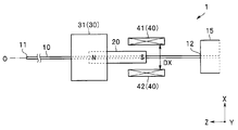
1組の第1の対向コイル30は、磁石20に光軸Oと直交する第1の方向(Y軸方向)の第1の磁界M1を印加する。1組の第2の対向コイル40は、磁石20に第1の方向(Y軸方向)および光軸Oと直交する第2の方向(X軸方向)の第2の磁界M2を印加する。
光ファイバ10は、例えばニッケルからなるファイバ保持部材(フェルール)の貫通孔に挿入され、固定端12から先端11までが、貫通孔から突出した振動部となっている。すなわち、光ファイバ10は、固定端12を起点とし先端11までの振動部が、第1の方向(Y軸方向)および第1の方向と直交する第2の方向(X軸方向)に振動する。第1の方向および第2の方向は光軸方向(Z軸方向)と直交している。なお、第1の方向がX軸方向で、第2の方向がY軸方向でも良いことは言うまでもない。
光源部91は、例えば赤、緑および青の三原色のCW(連続発振)レーザ光を射出する3つのレーザ光源からの光を合波して白色光として出射する。レーザ光源としては、例えばDPSSレーザ(半導体励起固体レーザ)やレーザダイオードを使用できる。もちろん、光源部91の構成はこれに限られず、一つのレーザ光源を用いるものであっても、他の複数の光源を用いるものであっても良い。
固定端12で片持ち保持されている光ファイバ10の振動部が、磁石20に印加された第1の磁界M1および第2の磁界M2によって振動することで、光ファイバ10の先端11から出射されるスポット照明光は、2次元走査され、被観察物を照明する。照明光により照明された被観察物の反射光は検出用の光ファイバ19を介して検出部92に入光する。検出部92は、反射光をスペクトル成分に分解し、フォトダイオードにより電気信号に変換する。制御部94は、光源部91、検出部92および駆動信号生成部93を同期制御するとともに、検出部92が出力する電気信号を処理して、画像を合成し、表示部95に表示する。使用者は、入力部96を介して、走査速度、表示画像の明るさ等の撮像システム90の設定を行う。
なお、光源部91、検出部92、駆動信号生成部93および制御部94は、同一の筐体に収納されていても良く、また、別々の筐体に収納されていても良い。
光ファイバ10は、光源部91からの光を導光し、自由端である先端11から照明光を出射する。なお、光ファイバ走査装置1は、光ファイバ10が出射する照明光を被観察物の表面で集光するように構成されている照明光学系を具備していてもよい。
検出用の光ファイバ19には、先端に集光用光学系が配設されていてもよい。なお、十分な検出光量を得るために光ファイバ走査装置1は複数の光ファイバ19を有する。
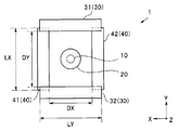
図2、図3および図4に示すように、第1の対向コイル30は、コイル31とコイル32とが対向配置されている。また、第2の対向コイル40は、コイル41とコイル42とが対向配置されている。
コイル31、コイル32、コイル41、およびコイル42(以下、「コイル31等」という。)は、シリコン基板等の基体の上に配設された導体パターンが平面内に巻回配置されているスパイラル平面コイルである。
なお、コイル31等は、絶縁層を介して2層以上のスパイラルコイルが接続されている多層平面コイルであってもよい。また、コイル31等が配設された可撓性基体が、筒状に変形していてもよい。さらにコイル31等が軟磁性体からなる磁気コアを有していてもよい。
チューブ型の磁石20は中心に貫通孔があり、貫通孔に光ファイバ10が挿入され接着剤(不図示)で固定されている。細長い磁石20は、光ファイバ10の光軸Oの方向に磁化されている。例えば、磁石20は前部(光ファイバ10の先端側)がN極に、後部(光ファイバ10の固定端側)がS極に着磁されている。第1の対向コイル30は、磁石20の前部に第1の磁界M1を印加する。第2の対向コイル40は、磁石20の後部に第2の磁界M2を印加する。すなわち、第1の対向コイル30は、第2の対向コイル40よりも、光ファイバ10の先端側に配置されており、両者の中心間の距離は磁石20の長さと略同じである。なお、磁石は、第1の磁界M1が印加される第1の磁石と、第2の磁界M2が印加される第2の磁石と、により構成されていてもよい。なお、第1の対向コイル30が、第2の対向コイル40よりも後端側(固定端側)に配置されており、第1の対向コイル30が、磁石20の後部に第1の磁界M1を印加し、第2の対向コイル40が磁石20の前部に第2の磁界M2を印加してもよい。
第1の方向への振動と第2の方向への振動との組み合わせにより、光ファイバ10の先端11は、XY平面内を所定の走査パターンで移動する。
第1の方向の振動パターン(Y軸走査)と第2の方向の振動パターン(X軸走査)との組み合わせにより、走査方式は、スパイラル走査、ラスター走査、またはリサージュ走査等となる。
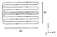
図5に示すラスター走査では第1の方向(Y軸方向)への低速走査と、第1の方向への走査中に行われる第2の方向(X軸方向)への高速走査とを組み合わせて行われる。図5では第1の方向(Y軸方向)のプラス側への振動時に画像信号を取得する例を示しているがマイナス側の振動時、または両側の振動時に画像信号を取得してもよい。また、表示部95が、横長画面の場合には、第1の方向(Y軸方向)の振幅AYよりも第2の方向(X軸方向)の振幅AXが大きい。
このため、第1の対向コイル30が発生する第1の磁界M1よりも、第2の対向コイル40が発生する第2の磁界M2を大きくしなければならない。
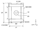
光ファイバ走査装置1では、第1の対向コイル30のコイル31とコイル32との間隔である第1の対向間隔DYと、第2の対向コイル40のコイル41とコイル42との間隔である第2の対向間隔DXとが、異なる。すなわち、第2の対向間隔DXが第1の対向間隔DYよりも短い。
対向コイルの中心、すなわち、磁石位置における磁界強度Mは、対向間隔Dの場合、(1/D2)である。例えば、第1の対向コイル30と第2の対向コイル40とに同じ電流値の駆動信号が流れた場合であっても、第2の対向間隔DXが第1の対向間隔DYの80%であれば、第2の磁界M2は第1の磁界M1の1.56倍となる。
光ファイバ走査装置1は、第1の磁界M1よりも大きい第2の磁界M2を発生することが容易であるため、効率的なスキャン照射を行うことができる。
なお、従来のファイバ走査装置では、例えば、磁石20の前部および後部に、それぞれ、2組の対向コイル、すなわち、第1の方向の磁界を発生する対向コイルおよび第2の方向の磁界を発生する対向コイル、が配設されていた。
スパイラル平面コイルであるコイル31等は、ターン数(巻回数)に比例して発生する磁界強度が大きくなる。平面コイルでは、同じピッチ(導体幅/スペース幅)の場合、ターン数を多くすると、コイルの大きさ、すなわち平面視寸法(外寸/面積)が大きくなる。このため、光軸の方向に対して同じ位置に2組の対向コイルが配置されている従来のファイバ走査装置では、直交配置されている2組の対向コイルの大きさは、その対向間隔により制限されていた。
これに対して、光ファイバ走査装置1では、磁石20の前部に磁界を印加するコイルは第1の対向コイル30だけしか配設されていない。また磁石20の後部に磁界を印加するコイルは第2の対向コイル40だけしか配設されていない。すなわち、それぞれの位置には1組の対向コイルだけしか配設されていない。
なお、すでに説明したように、第1の対向コイル30および第2の対向コイル40は、それぞれが複数の多層コイルを有していてもよい。また、第1の対向コイル30および第2の対向コイル40は、それぞれが同じ方向の磁界を印加する複数組の対向コイルからなる複合対向コイルであってもよい。
このため、図4に示すように、第2の対向コイル40の対向間隔DXが、第1の対向コイル30の幅LYよりも小さくてもよいし、第1の対向コイル30の対向間隔DYが、第2の対向コイル40の幅LXよりも小さくてもよい。言い替えれば、光軸方向から観察(透明視)したときに、第1の対向コイル30と第2の対向コイル40とは一部が交差している。すなわち、直交配置されている2組の対向コイル30、40の大きさは、対向間隔による制限がない。
また、光ファイバ走査装置1は、第1の対向コイル30のターン数と第2の対向コイル40のターン数とを、異なるように設定できる。光ファイバ走査装置1は、第2の対向コイル40(コイル41、42)のターン数を第1の対向コイル30(コイル31、32)のターン数よりも多くできるため、効率的なスキャン照射を行うことができる。
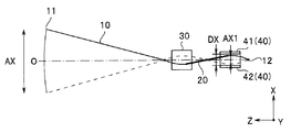
さらに、光ファイバ走査装置1では、図6に示すように、光ファイバ10は、第1の方向(Y軸方向)においては、1次振動する。これに対して、図7に示すように、光ファイバ10は第2の方向(X軸方向)においては、3次振動する。
すでに説明したように、第1の対応コイル30(31、32)は、磁石20の前部に磁界を印加する。第2の対向コイル40(41、42)は、磁石20の後部に磁界を印加する。
3次振動する光ファイバ10は、平面視すると、例えば、固定端12、磁石20の位置、および、第1の対向コイル30の位置よりも先端側の3箇所に振動の節(vibration node)、すなわち、振動していない点がある。そして、振動の節の間に、振幅が大きい振動の腹(vibration antinode)がある。
3次振動する光ファイバは、固定端12に最も近い振動の腹における振幅A1Xは、先端11の振幅AXに比べて、例えば、0.2AXであり、非常に小さい。このため、第2の対向コイル40の第2の対向間隔DXを小さくしても、振動した光ファイバがコイルと接触するおそれはない。
さらに、3次振動する第2の方向の共振周波数FRXは、1次振動する第1の方向の共振周波数FRYの、例えば、20倍となるため、高速走査が容易である。
このため、光ファイバ走査装置1は、特にラスター走査を効率的に行うことができる。もちろん、光ファイバ走査装置1が他の走査方式の場合であっても、3次振動する方向への走査が効率的であることは言うまでも無い。
なお、光ファイバ10は、第2の方向が、1次振動する第1の方向よりも高速走査が容易で振幅を大きくしやすい高次振動する2次振動してもよい。さらに、光ファイバ10は、第1の方向に2次振動し、第2の方向に3次振動してもよいし、もちろん、第1の方向および第2の方向に1次振動してもよい。
<第1実施形態の変形例>
第1実施形態の変形例の光ファイバ走査装置1Aは、光ファイバ走査装置1と類似し同じ効果を有しているため、同じ機能の構成要素には同じ符号を付し説明は省略する。
第1実施形態の変形例の光ファイバ走査装置1Aは、光ファイバ走査装置1と類似し同じ効果を有しているため、同じ機能の構成要素には同じ符号を付し説明は省略する。
図8に示すように、光ファイバ走査装置1Aでは、第1の対向コイル30(31、32)の大きさと第2の対向コイル40A(41A、42A)の大きさが異なる。図9Aに示すように第1の対向コイル30(31、32)は、3ターンコイルである。これに対して図9Bに示す第2の対向コイル40A(41A、42A)は4ターンコイルである。
このため、第2の対向コイル40A(41A、42A)の外寸LXは、第1の対向コイル30(31、32)の外寸LYよりも、約20%大きい。
なお、図9A、9Bに示すように、コイル31、32、41A、42Aは、外形が正方形のため、縦方向の外寸も横方向の外寸も同じ、LYまたはLXであった。しかし、コイル31、32、41A、42Aは、外形が長方形でもよいことは言うまでも無い。
また、すでに説明した光ファイバ走査装置1と同じように、光ファイバ走査装置1Aでも、直交配置されている2組の対向コイル30、40Aは、配設位置が異なるため、その大きさ(外寸)は、対向間隔による制限がない。
光ファイバ走査装置1Aでは、より大きな磁界を発生する第2の対向コイル40A(41A、42A)が、第1の対向コイル30(31、32)よりもターン数が多い大きなコイルであるため、光ファイバ走査装置1よりも更に効率的なスキャン照射を行うことができる。
なお、駆動信号生成部93が、第1の対向コイル30に流す駆動信号の電流値と第2の対向コイル40に流す駆動信号の電流値とを異なるように設定してもよい。
平面コイルに流せる駆動信号の電流値の上限は、コイルパターン厚さが同じ場合にはコイルパターン幅が広いほど高電流となる。例えば、第2の対向コイル40A(41A、42A)のコイルパターン幅WBが、第1の対向コイル30(31、32)のコイルパターン幅WAよりも広いと、同じターン数であっても、コイルの大きさ(外寸)が異なってくる。より広いコイルパターン幅WBの第2の対向コイル40A(41A、42A)は、第1の対向コイル30(31、32)よりも、高電流の駆動信号を流すことができるため、より大きな磁界を発生できる。
また、光ファイバ走査装置1Aは、光ファイバ走査装置1と同じように第2の対向コイル40Aの対向間隔DXが第1の対向コイル30の対向間隔DYよりも小さい。しかし、外寸LXが外寸LYよりも大きければ、対向間隔DXが対向間隔DYと同じであっても、従来の光ファイバ走査装置よりも効率的なスキャン照射を行うことができることは言うまでも無い。
また、光ファイバ走査装置1Aにおいても、光ファイバ10が第1の方向においては1次振動し、第2の方向においては高次振動することで、より効率的なラスター走査を行うことができる。
以上の説明のように、2組の対向コイルの対向間隔、大きさ(ターン数/コイルパターン幅)および駆動信号の電流値の少なくともいずれかを変えることで、2組の対向コイルの駆動能力(印加磁界強度)を変えることができる。
<第2実施形態>
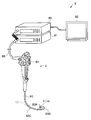
図10に示すように、本実施形態の内視鏡9を含む内視鏡システム8は、内視鏡9と、プロセッサ80と、光源装置81と、モニタ82と、を具備する。プロセッサ80は、図1に示した撮像システム90の、光源部91と検出部92と駆動信号生成部93と制御部94と入力部96とを含んでいる。光源装置81は光源部91に、モニタ82は表示部95に相当する。
図10に示すように、本実施形態の内視鏡9を含む内視鏡システム8は、内視鏡9と、プロセッサ80と、光源装置81と、モニタ82と、を具備する。プロセッサ80は、図1に示した撮像システム90の、光源部91と検出部92と駆動信号生成部93と制御部94と入力部96とを含んでいる。光源装置81は光源部91に、モニタ82は表示部95に相当する。
内視鏡9は、挿入部83と操作部84とユニバーサルコード85とを有する。内視鏡9は、挿入部83が被検体の体腔内に挿入されて、被検体の体内画像を撮影し画像信号を出力する。
挿入部83は、先端部83Aと、先端部83Aの基端側に連設された湾曲自在な湾曲部83Bと、湾曲部83Bの基端側に連設された軟性部83Cとによって構成される。なお、内視鏡9は硬性鏡であってもよいし、工業用であってもよい。
内視鏡9の挿入部83の基端側には、内視鏡9を操作する各種ボタン類が設けられた操作部84が配設されている。湾曲部83Bは、操作部84の操作によって湾曲する。
内視鏡9は、光ファイバ走査装置1(1A)を挿入部83の先端部83Aに有する走査型内視鏡である。走査型内視鏡は、撮像素子部を含む内視鏡よりも先端部83Aの細径化が容易で低侵襲である。さらに、光ファイバ走査装置1は、撮像素子部と異なり、放射線による劣化が顕著ではない。そして、光ファイバ走査装置1(1A)は、特に、効率的なスキャン照射を行うことができるため、内視鏡9は、効率的である。
本発明は、上述した各実施形態または変形例に限定されるものではなく、発明の趣旨を逸脱しない範囲内において種々の変更、組み合わせ、および応用が可能であることは勿論である。
1、1A・・・光ファイバ走査装置
8・・・内視鏡システム
9・・・内視鏡
10・・・光ファイバ
11・・・先端
12・・・固定端
19・・・光ファイバ
20・・・磁石
30、・・・第1の対向コイル
31、32・・・コイル
40、40A・・・第2の対向コイル
41、42・・・コイル
80・・・プロセッサ
81・・・光源装置
82・・・モニタ
83・・・挿入部
83A・・・先端部
91・・・光源部
92・・・検出部
93・・・駆動信号生成部
94・・・制御部
95・・・表示部
96・・・入力部
8・・・内視鏡システム
9・・・内視鏡
10・・・光ファイバ
11・・・先端
12・・・固定端
19・・・光ファイバ
20・・・磁石
30、・・・第1の対向コイル
31、32・・・コイル
40、40A・・・第2の対向コイル
41、42・・・コイル
80・・・プロセッサ
81・・・光源装置
82・・・モニタ
83・・・挿入部
83A・・・先端部
91・・・光源部
92・・・検出部
93・・・駆動信号生成部
94・・・制御部
95・・・表示部
96・・・入力部
Claims (9)
- 先端から照明光を出射し、固定端で片持ち保持されている光ファイバと、
前記光ファイバの光軸の方向に磁化され、前記光ファイバに配設されている磁石と、
前記磁石に磁界を印加する複数組の対向コイルと、を具備し、
前記複数組の対向コイルが、前記光軸と直交する第1の方向の第1の磁界を前記磁石に印加する1組の第1の対向コイルと、前記第1の方向および前記光軸と直交する第2の方向の第2の磁界を前記磁石に印加する1組の第2の対向コイルと、からなり、
前記第1の対向コイルが前記磁石の前部に前記第1の磁界を印加し、前記第2の対向コイルが前記磁石の後部に前記第2の磁界を印加するように、前記複数組の対向コイルが配置されていることを特徴とする光ファイバ走査装置。 - 前記第1の対向コイルの第1の対向間隔と、前記第2の対向コイルの第2の対向間隔とが、異なることを特徴とする請求項1に記載の光ファイバ走査装置。
- 前記第1の対向コイルの大きさと前記第2の対向コイルの大きさとが、異なることを特徴とする請求項1に記載の光ファイバ走査装置。
- 前記第1の対向コイルのターン数と前記第2の対向コイルのターン数とが、異なることを特徴とする請求項3に記載の光ファイバ走査装置。
- 前記第1の対向コイルのコイルパターン幅と前記第2の対向コイルのコイルパターン幅とが、異なることを特徴とする請求項3または請求項4に記載の光ファイバ走査装置。
- 前記第1の対向コイルに印加される駆動信号の電流値と前記第2の対向コイルに印加される駆動信号の電流値とが、異なることを特徴とする請求項1から請求項5のいずれか1項に記載の光ファイバ走査装置。
- 前記光ファイバが、前記第1の方向または前記第2の方向の少なくともいずれかの方向において、高次振動することを特徴とする請求項1から請求項6のいずれか1項に記載の光ファイバ走査装置。
- 前記光ファイバが、高次振動する方向と直交する方向において、1次振動することを特徴とする請求項7に記載の光ファイバ走査装置。
- 請求項1から請求項8のいずれか1項に記載の光ファイバ走査装置を、挿入部の先端部に具備することを特徴とする内視鏡。
Priority Applications (1)
| Application Number | Priority Date | Filing Date | Title |
|---|---|---|---|
| PCT/JP2017/023250 WO2018235277A1 (ja) | 2017-06-23 | 2017-06-23 | 光ファイバ走査装置および内視鏡 |
Applications Claiming Priority (1)
| Application Number | Priority Date | Filing Date | Title |
|---|---|---|---|
| PCT/JP2017/023250 WO2018235277A1 (ja) | 2017-06-23 | 2017-06-23 | 光ファイバ走査装置および内視鏡 |
Publications (1)
| Publication Number | Publication Date |
|---|---|
| WO2018235277A1 true WO2018235277A1 (ja) | 2018-12-27 |
Family
ID=64737756
Family Applications (1)
| Application Number | Title | Priority Date | Filing Date |
|---|---|---|---|
| PCT/JP2017/023250 Ceased WO2018235277A1 (ja) | 2017-06-23 | 2017-06-23 | 光ファイバ走査装置および内視鏡 |
Country Status (1)
| Country | Link |
|---|---|
| WO (1) | WO2018235277A1 (ja) |
Cited By (1)
| Publication number | Priority date | Publication date | Assignee | Title |
|---|---|---|---|---|
| CN110727072A (zh) * | 2019-11-20 | 2020-01-24 | 杭州昱华科技有限公司 | 一种用于通信工程的光纤交接箱 |
Citations (5)
| Publication number | Priority date | Publication date | Assignee | Title |
|---|---|---|---|---|
| US5727098A (en) * | 1994-09-07 | 1998-03-10 | Jacobson; Joseph M. | Oscillating fiber optic display and imager |
| JP2008116922A (ja) * | 2006-09-14 | 2008-05-22 | Optiscan Pty Ltd | 光ファイバ走査装置 |
| WO2013031824A1 (ja) * | 2011-09-02 | 2013-03-07 | オリンパス株式会社 | 光走査デバイス及びこれを備えた内視鏡、顕微鏡、プロジェクター |
| WO2015037231A1 (ja) * | 2013-09-11 | 2015-03-19 | オリンパス株式会社 | 光走査装置 |
| JP2015211761A (ja) * | 2014-05-02 | 2015-11-26 | オリンパス株式会社 | 光ファイバ走査装置、および光走査型内視鏡 |
-
2017
- 2017-06-23 WO PCT/JP2017/023250 patent/WO2018235277A1/ja not_active Ceased
Patent Citations (5)
| Publication number | Priority date | Publication date | Assignee | Title |
|---|---|---|---|---|
| US5727098A (en) * | 1994-09-07 | 1998-03-10 | Jacobson; Joseph M. | Oscillating fiber optic display and imager |
| JP2008116922A (ja) * | 2006-09-14 | 2008-05-22 | Optiscan Pty Ltd | 光ファイバ走査装置 |
| WO2013031824A1 (ja) * | 2011-09-02 | 2013-03-07 | オリンパス株式会社 | 光走査デバイス及びこれを備えた内視鏡、顕微鏡、プロジェクター |
| WO2015037231A1 (ja) * | 2013-09-11 | 2015-03-19 | オリンパス株式会社 | 光走査装置 |
| JP2015211761A (ja) * | 2014-05-02 | 2015-11-26 | オリンパス株式会社 | 光ファイバ走査装置、および光走査型内視鏡 |
Cited By (2)
| Publication number | Priority date | Publication date | Assignee | Title |
|---|---|---|---|---|
| CN110727072A (zh) * | 2019-11-20 | 2020-01-24 | 杭州昱华科技有限公司 | 一种用于通信工程的光纤交接箱 |
| CN110727072B (zh) * | 2019-11-20 | 2023-11-10 | 杭州昱华科技有限公司 | 一种用于通信工程的光纤交接箱 |
Similar Documents
| Publication | Publication Date | Title |
|---|---|---|
| JP6057743B2 (ja) | 光走査装置 | |
| JP6086674B2 (ja) | 光走査装置 | |
| US10502947B2 (en) | Optical fiber scanning apparatus and optical scanning type endoscope | |
| JP6021575B2 (ja) | 光ファイバ走査装置、光ファイバ走査装置の駆動方法および光走査型内視鏡 | |
| JP2014145941A (ja) | 光走査型内視鏡 | |
| JP6422872B2 (ja) | 光走査装置 | |
| WO2018235277A1 (ja) | 光ファイバ走査装置および内視鏡 | |
| JP2015139537A (ja) | 光走査型内視鏡 | |
| JP6006127B2 (ja) | 光走査装置 | |
| US11213188B2 (en) | Optical fiber scanning device, optical scanning type endoscope and endoscope system | |
| WO2016116963A1 (ja) | 光走査方法及び光走査装置 | |
| US20190317316A1 (en) | Optical fiber scanning apparatus and endoscope | |
| WO2016116962A1 (ja) | 光走査方法及び光走査装置 | |
| JP2015211760A (ja) | 光ファイバ走査装置、および光走査型内視鏡 | |
| JP6640221B2 (ja) | 光走査型内視鏡および光ファイバ走査装置 | |
| US11391942B2 (en) | Endoscope having optical fiber scanning apparatus | |
| JP6071590B2 (ja) | 光走査ユニット、光走査型観察装置、および光走査型表示装置 | |
| JP2018105970A (ja) | 光ファイバ走査装置、内視鏡および光ファイバ走査装置の製造方法 | |
| JP2015128548A (ja) | 光走査型内視鏡 | |
| JP6173035B2 (ja) | 光走査デバイス、光走査型観察装置および光走査型画像表示装置 | |
| JP2015128549A (ja) | 光走査型内視鏡 |
Legal Events
| Date | Code | Title | Description |
|---|---|---|---|
| 121 | Ep: the epo has been informed by wipo that ep was designated in this application |
Ref document number: 17914743 Country of ref document: EP Kind code of ref document: A1 |
|
| NENP | Non-entry into the national phase |
Ref country code: DE |
|
| 122 | Ep: pct application non-entry in european phase |
Ref document number: 17914743 Country of ref document: EP Kind code of ref document: A1 |
|
| NENP | Non-entry into the national phase |
Ref country code: JP |