WO2018230652A1 - Système de soupape - Google Patents
Système de soupape Download PDFInfo
- Publication number
- WO2018230652A1 WO2018230652A1 PCT/JP2018/022748 JP2018022748W WO2018230652A1 WO 2018230652 A1 WO2018230652 A1 WO 2018230652A1 JP 2018022748 W JP2018022748 W JP 2018022748W WO 2018230652 A1 WO2018230652 A1 WO 2018230652A1
- Authority
- WO
- WIPO (PCT)
- Prior art keywords
- housing
- valve
- valve body
- partition wall
- hole
- Prior art date
Links
Images


Classifications
-
- F—MECHANICAL ENGINEERING; LIGHTING; HEATING; WEAPONS; BLASTING
- F16—ENGINEERING ELEMENTS AND UNITS; GENERAL MEASURES FOR PRODUCING AND MAINTAINING EFFECTIVE FUNCTIONING OF MACHINES OR INSTALLATIONS; THERMAL INSULATION IN GENERAL
- F16K—VALVES; TAPS; COCKS; ACTUATING-FLOATS; DEVICES FOR VENTING OR AERATING
- F16K11/00—Multiple-way valves, e.g. mixing valves; Pipe fittings incorporating such valves
- F16K11/02—Multiple-way valves, e.g. mixing valves; Pipe fittings incorporating such valves with all movable sealing faces moving as one unit
- F16K11/06—Multiple-way valves, e.g. mixing valves; Pipe fittings incorporating such valves with all movable sealing faces moving as one unit comprising only sliding valves, i.e. sliding closure elements
- F16K11/072—Multiple-way valves, e.g. mixing valves; Pipe fittings incorporating such valves with all movable sealing faces moving as one unit comprising only sliding valves, i.e. sliding closure elements with pivoted closure members
- F16K11/076—Multiple-way valves, e.g. mixing valves; Pipe fittings incorporating such valves with all movable sealing faces moving as one unit comprising only sliding valves, i.e. sliding closure elements with pivoted closure members with sealing faces shaped as surfaces of solids of revolution
-
- F—MECHANICAL ENGINEERING; LIGHTING; HEATING; WEAPONS; BLASTING
- F16—ENGINEERING ELEMENTS AND UNITS; GENERAL MEASURES FOR PRODUCING AND MAINTAINING EFFECTIVE FUNCTIONING OF MACHINES OR INSTALLATIONS; THERMAL INSULATION IN GENERAL
- F16K—VALVES; TAPS; COCKS; ACTUATING-FLOATS; DEVICES FOR VENTING OR AERATING
- F16K27/00—Construction of housing; Use of materials therefor
-
- F—MECHANICAL ENGINEERING; LIGHTING; HEATING; WEAPONS; BLASTING
- F16—ENGINEERING ELEMENTS AND UNITS; GENERAL MEASURES FOR PRODUCING AND MAINTAINING EFFECTIVE FUNCTIONING OF MACHINES OR INSTALLATIONS; THERMAL INSULATION IN GENERAL
- F16K—VALVES; TAPS; COCKS; ACTUATING-FLOATS; DEVICES FOR VENTING OR AERATING
- F16K31/00—Actuating devices; Operating means; Releasing devices
- F16K31/02—Actuating devices; Operating means; Releasing devices electric; magnetic
- F16K31/04—Actuating devices; Operating means; Releasing devices electric; magnetic using a motor
Definitions
- This disclosure relates to a valve device.
- a partition wall is provided in the opening of the housing so as to separate the internal space of the housing from the outside of the housing.
- a drive unit for rotationally driving the valve is provided on the side opposite to the internal space with respect to the partition wall.
- the outer edge portion of the drive unit cover fixed to the housing protrudes outward from the end portion in the width direction of the housing. There is a risk. In this case, it may be difficult to mount the valve device in a narrow space in the engine room of the vehicle.
- An object of the present disclosure is to provide a valve device that can be mounted in a narrow space.
- the present disclosure is a valve device that can control cooling water of a heating element of a vehicle, and includes a housing, a valve, a partition wall, a drive unit cover, and a drive unit.
- the drive unit cover includes a cover main body that forms a drive unit space, and a cover fixing unit that is formed on the outer edge of the cover main body and is fixed to the housing main body.
- the cover fixing portion is formed so as not to protrude outward from at least one of both end portions in a direction perpendicular to the mounting surface of the housing body.
- valve device can be mounted in a narrow space of the vehicle.
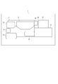
- FIG. 1 is a schematic diagram showing a cooling system to which the valve device of the first embodiment is applied.
- FIG. 2 is a schematic diagram showing an arrangement of the valve device of the first embodiment in a vehicle.
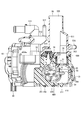
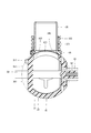
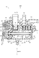
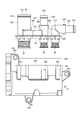
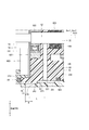
- FIG. 3 is a cross-sectional view showing the valve device of the first embodiment
- FIG. 4 is a cross-sectional view showing the vicinity of the seal unit of the valve device of the first embodiment
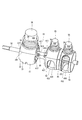
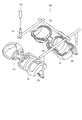
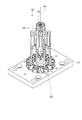
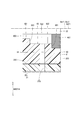
- FIG. 5 is a cross-sectional perspective view showing the valve device of the first embodiment
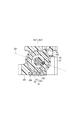
- 6 is a cross-sectional view taken along line VI-VI in FIG. FIG.
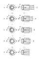
- FIG. 7 is a diagram showing the relationship between the rotational position of the valve body of the valve device of the first embodiment and the open / closed state of the valve body opening
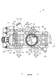
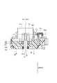
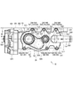
- FIG. 8 is a view of FIG. 3 as viewed from the direction of arrow VIII.
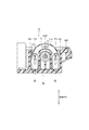
- FIG. 9 is a diagram of FIG. 3 viewed from the direction of the arrow IX.
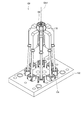
- FIG. 10 is a perspective view showing a part of the valve device of the first embodiment.
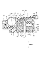
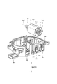
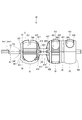
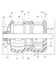
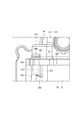
- FIG. 11 is a cross-sectional view showing the vicinity of the drive unit of the valve device of the first embodiment.
- FIG. 12 is a cross-sectional view showing the vicinity of the drive unit of the valve device of the first embodiment
- FIG. 13 is a cross-sectional view showing the vicinity of the drive unit of the valve device of the first embodiment, FIG.
- FIG. 14 is a cross-sectional view showing the vicinity of the drive unit of the valve device of the first embodiment
- FIG. 15 is a plan view showing a drive unit of the valve device of the first embodiment
- FIG. 16 is a cross-sectional view showing the vicinity of the drive unit of the valve device of the first embodiment
- FIG. 17 is an exploded perspective view showing a part of the drive unit cover and the drive unit of the valve device of the first embodiment
- FIG. 18 is an exploded perspective view showing a drive unit cover and a part of the drive unit of the valve device of the first embodiment.
- FIG. 19 is a diagram illustrating a drive unit of the valve device according to the second embodiment.
- FIG. 20 is a view showing a valve of the valve device of the third embodiment, FIG.
- FIG. 21 is a diagram showing a part of a valve of the valve device of the third embodiment
- FIG. 22 is a perspective view showing a valve of the valve device of the third embodiment
- FIG. 23 is a perspective view showing a valve of the valve device of the third embodiment
- FIG. 24 is a diagram showing a part of a valve of the valve device of the third embodiment
- FIG. 25 is a cross-sectional view showing a part of a valve and a seal unit of the valve device of the third embodiment
- FIG. 26 is a perspective view showing a valve and a seal unit of the valve device of the third embodiment
- FIG. 27 is a perspective view showing a part of a valve of the valve device of the third embodiment
- FIG. 22 is a perspective view showing a valve of the valve device of the third embodiment
- FIG. 23 is a perspective view showing a valve of the valve device of the third embodiment
- FIG. 24 is a diagram showing a part of a valve of the valve device of the third embodiment
- FIG. 25 is
- FIG. 28 is a cross-sectional view showing a part of a valve of the valve device of the third embodiment
- FIG. 29 is a diagram for explaining a manufacturing process of the valve of the valve device according to the third embodiment
- FIG. 30 is a view for explaining a manufacturing process of the valve of the valve device of the third embodiment
- FIG. 31 is a diagram for explaining a manufacturing process of the valve of the valve device of the third embodiment
- FIG. 32 is a diagram for explaining a manufacturing process of the valve of the valve device according to the third embodiment.
- FIG. 33 is a cross-sectional view showing a part of a valve and a seal unit of the valve device of the fourth embodiment
- FIG. 34 is a cross-sectional view showing a part of the valve of the valve device of the fifth embodiment
- FIG. 35 is a perspective view showing a mold apparatus used in the valve manufacturing process of the valve apparatus of the fifth embodiment
- FIG. 36 is a perspective view showing a part of a mold apparatus used in the valve manufacturing process of the valve apparatus of the fifth embodiment
- FIG. 37 is a perspective view showing a part of a mold apparatus used in the valve manufacturing process of the valve apparatus of the fifth embodiment
- FIG. 38 is a perspective view showing a part of a mold apparatus used in the valve manufacturing process of the valve apparatus of the fifth embodiment
- FIG. 39 is a diagram for explaining a manufacturing process of the valve of the valve device according to the fifth embodiment.
- FIG. 40 is a diagram for explaining a manufacturing process of the valve of the valve device according to the fifth embodiment.
- FIG. 40 is a diagram for explaining a manufacturing process of the valve of the valve device according to the fifth embodiment.
- FIG. 41 is a diagram for explaining a manufacturing process of the valve of the valve device according to the fifth embodiment.
- FIG. 42 is a cross-sectional view showing the valve device of the sixth embodiment
- FIG. 43 is a view showing the valve device of the sixth embodiment
- FIG. 44 is a schematic diagram showing an arrangement of the valve device of the sixth embodiment in a vehicle.
- FIG. 45 is a view showing a valve device of a sixth embodiment
- FIG. 46 is a perspective view showing the valve device of the sixth embodiment
- 47 is a diagram of FIG. 42 viewed from the direction of arrow XLVII.
- FIG. 48 is a perspective view showing the valve device of the sixth embodiment
- FIG. 49 is a diagram showing a part of the valve device of the sixth embodiment
- FIG. 50 is a cross-sectional view showing a pipe member, a seal unit, and a gasket of the valve device of the sixth embodiment.
- FIG. 51 is an exploded view showing a part of the valve device of the sixth embodiment
- FIG. 52 is a cross-sectional view showing the vicinity of the partition wall through-hole of the valve device of the sixth embodiment
- FIG. 53 is a cross-sectional view showing the vicinity of the partition wall through-hole of the valve device of the seventh embodiment
- FIG. 54 is a cross-sectional view showing the vicinity of the partition wall through-hole of the valve device of the eighth embodiment
- FIG. 55 is a cross-sectional view showing the vicinity of the partition wall through-hole of the valve device of the ninth embodiment, FIG.
- FIG. 56 is a view showing a partition wall through hole of the valve device of the tenth embodiment
- FIG. 57 is a view showing a partition wall through-hole of the valve device of the tenth embodiment
- FIG. 58 is a diagram showing a partition through hole of the valve device of the eleventh embodiment
- FIG. 59 is a cross-sectional view showing the vicinity of the partition wall through-hole of the valve device of the twelfth embodiment
- FIG. 60 is a view showing a partition wall through hole of the valve device according to the thirteenth embodiment.
- valve devices according to a plurality of embodiments will be described with reference to the drawings. Note that, in a plurality of embodiments, substantially the same components are denoted by the same reference numerals, and description thereof is omitted. In the plurality of embodiments, substantially the same constituent parts have the same or similar operational effects.
- FIG. 1 A valve device and a cooling system according to the first embodiment are shown in FIG.
- the valve device 10 is applied to the cooling system 9 of the vehicle 1.
- the vehicle 1 is equipped with an internal combustion engine (hereinafter referred to as “engine”) 2 as a heating element, a cooling system 9, a heater 6, a device 7, and the like.
- engine internal combustion engine
- the cooling system 9 includes a valve device 10, a water pump 4, a radiator 5, an electronic control unit (hereinafter referred to as “ECU”) 8, and the like.
- the water pump 4 pumps the cooling water toward the water jacket 3 of the engine 2.
- the valve device 10 is provided at the outlet of the water jacket 3, for example, and adjusts the flow rate of cooling water sent to the radiator 5, the heater 6, and the device 7.
- the radiator 5 is a heat exchanger, and performs heat exchange between the cooling water and air to lower the temperature of the cooling water.
- the heater 6 and the device 7 are provided between the valve device 10 and the water pump 4.
- the device 7 includes, for example, an oil cooler, an EGR cooler, an ATF (automatic transmission oil) cooler, and the like.
- the ECU 8 can control the operation of the valve device 10 and control the flow rate of the cooling water sent to the radiator 5, the heater 6, and the device 7.
- the valve device 10 includes a housing 20, a valve 30, a seal unit 35, a pipe member 50, a partition wall 60, a driving unit 70, a driving unit cover 80, and the like.
- the housing 20 has a housing body 21 and the like.
- the housing body 21 is made of, for example, resin, and forms an internal space 200 inside.
- a flat mounting surface 201 is formed on the outer wall of the housing body 21.
- a flat pipe mounting surface 202 is formed on the outer wall of the housing body 21 opposite to the mounting surface 201.
- the attachment surface 201 is formed so as to be substantially parallel to the pipe attachment surface 202.
- the housing body 21 has a housing opening 210 that connects the internal space 200 and the outside of the housing body 21.
- the housing body 21 has a cylindrical housing inner wall 211 having one end connected to the housing opening 210 to form the internal space 200.
- the housing inner wall 211 is formed so that the shaft is substantially parallel to the attachment surface 201 and the pipe attachment surface 202.
- the housing 20 has an inlet port 220 that opens to the mounting surface 201 and connects the internal space 200 and the outside of the housing body 21.
- the opening of the inlet port 220 in the mounting surface 201 is circular.
- the inlet port 220 corresponds to “port” and “first port”.
- the housing 20 has outlet ports 221, 222, and 223 that open to the pipe mounting surface 202 and connect the internal space 200 and the outside of the housing body 21.
- the exit ports 221, 222, and 223 correspond to “port” and “second port”.
- the housing 20 has a relief port 224 that opens in the pipe mounting surface 202 and connects the internal space 200 and the outside of the housing body 21.
- the outlet ports 221, 222, and 223 are formed so as to be arranged in this order from the end of the housing body 21 opposite to the housing opening 210 toward the housing opening 210.
- the inner diameter of the outlet port 221 is larger than the inner diameter of the outlet ports 222 and 223.
- the valve 30 has a valve body 31, a shaft 32, and the like.
- the valve body 31 is made of, for example, resin.
- the valve body 31 is provided in the internal space 200 so as to be rotatable around the rotation axis Axr1.
- the rotation axis Axr1 is set to be substantially parallel to the axis of the housing inner wall 211.
- the valve body 31 includes a first divided body 33 and a second divided body 34 that are divided into two by a virtual plane Vp1 including the rotation axis Axr1, and the first divided body 33 and the second divided body 34 are joined to each other. The surfaces are joined (see FIG. 6).
- the valve element 31 has ball valves 41, 42, 43, a cylindrical connection part 44, and a cylindrical valve connection part 45.
- the ball valves 41, 42, and 43 correspond to “first ball valve”, “second ball valve”, and “third ball valve”, respectively.
- the cylindrical connecting portion 44 and the cylindrical valve connecting portion 45 correspond to “cylindrical portions”.
- Each of the ball valves 41, 42, and 43 is formed in a substantially spherical shape, and forms a valve body passage 300 inside.
- the outer peripheral walls of the ball valves 41, 42, and 43 are formed in a spherical shape that protrudes outward in the diameter direction of the rotation axis Axr1.
- the inner peripheral walls of the ball valves 41, 42, 43 are formed in a spherical shape so as to be recessed outward of the diameter of the rotation axis Axr1.
- the cylindrical connecting portion 44 is formed in a cylindrical shape so as to connect the ball valve 41 and the ball valve 42.
- the cylindrical valve connecting portion 45 is formed in a cylindrical shape so as to connect the ball valve 42 and the ball valve 43.
- the cylindrical valve connection part 45 forms the valve body flow path 300 inside.
- the ball valve 41, the cylindrical connection portion 44, the ball valve 42, the cylindrical valve connection portion 45, and the ball valve 43 are integrally formed in this order.
- valve body openings 410, 420, and 430 that connect the valve body flow path 300 and the outside of the valve body 31 are formed.
- An inter-valve space 400 is formed between the ball valve 41 and the ball valve 42 on the radially outer side of the cylindrical connecting portion 44. The inter-valve space 400 communicates with the valve body flow paths 300 of the ball valves 41 and 42.
- valve body opening 410 corresponds to the position of the outlet port 221
- the inter-valve space 400 corresponds to the position of the inlet port 220
- the valve body opening 420 corresponds to the outlet port 222
- the valve body opening 430 is provided in the internal space 200 so as to correspond to the position of the outlet port 223.
- the shaft 32 is formed in a rod shape with, for example, metal, and is provided on the rotation axis Axr1.
- the shaft 32 is provided integrally with the valve body 31.
- the shaft 32 can rotate around the rotation axis Axr1 together with the valve body 31.
- the pipe member 50 is made of, for example, resin. As shown in FIGS. 3 and 8, the pipe member 50 includes pipe portions 511 to 517, a pipe connecting portion 52, and the like. Each of the pipe portions 511 to 517 is formed in a cylindrical shape.
- the pipe part 511 is provided so that one end is located inside the outlet port 221.
- the pipe portion 512 is provided so that one end is located inside the outlet port 222.
- the pipe portion 513 is provided so that one end is located inside the outlet port 223.
- the pipe portion 514 is provided so that one end thereof corresponds to the position of the relief port 224.
- the pipe part 515 is provided so that one end is connected to the pipe part 511 and the pipe part 514.
- the pipe part 516 is provided so that one end is connected to the pipe part 511.
- the pipe portion 517 is provided so that one end is connected to the pipe portion 512.
- the pipe connecting part 52 is formed to connect one end side of the pipe parts 511 to 515.
- the pipe member 50 is fixed to the housing main body 21 so that the pipe connecting portion 52 contacts the pipe mounting surface 202. Between the pipe connecting portion 52 and the pipe mounting surface 202, a gasket 509 is provided that can hold the pipe member 50 and the housing body 21 in a liquid-tight manner.
- the other end of the pipe parts 511, 514, 515 is connected to the radiator 5 via a hose or the like.
- the other end of the pipe part 512 is connected to the heater 6 via a hose or the like.
- the other end of the pipe part 513 is connected to the device 7 via a hose or the like.
- the other end of the pipe portion 516 is connected to a reservoir tank (not shown) via a hose or the like.
- the other end of the pipe part 517 is connected to a throttle (not shown) via a hose or the like.
- the seal unit 35 is provided in each of the outlet ports 221, 222, and 223. As shown in FIG. 4, the seal unit 35 includes a valve seal 36, a sleeve 371, a spring 372, and a seal member 373.
- the valve seal 36 is formed in a substantially annular shape with, for example, resin, and has a seal opening 360 inside.
- the valve seal 36 is provided so that one surface thereof is in contact with the outer peripheral wall of the valve body 31, and can be liquid-tightly maintained between the valve seal 36 and the outer peripheral wall of the valve body 31.
- the sleeve 371 is formed in a cylindrical shape from, for example, metal, and holds the valve seal 36 at one end. The other end of the sleeve 371 is located inside one end of the pipe portion 511.
- the spring 372 is provided between one end of the sleeve 371 and one end of the pipe portion 511, and urges the valve seal 36 together with the sleeve 371 toward the valve body 31.
- the seal member 373 is formed in an annular shape by rubber, for example, is provided between one end of the pipe portion 511 and the outer peripheral wall of the sleeve 371, and can hold the space between the pipe portion 511 and the sleeve 371 in a liquid-tight manner.
- seal units 35 provided at the outlet ports 222 and 223 are configured in the same manner as the seal unit 35 provided at the outlet port 221, description thereof will be omitted.
- the three seal units 35 are assembled to one ends of the pipe portions 511, 512, and 513, respectively.
- the partition wall 60 is made of, for example, resin.
- the partition wall 60 is formed separately from the housing body 21.
- the partition wall 60 has a partition wall body 61 and the like.
- the partition wall body 61 is formed in a substantially disk shape.
- the partition wall 60 is provided in the housing body 21 so that the partition wall body 61 closes the housing opening 210.
- the partition wall 60 has a shaft insertion hole 62 that penetrates the center of the partition wall body 61 in the thickness direction.
- the valve 30 is provided such that one end of the shaft 32 is inserted through the shaft insertion hole 62.
- One end of the shaft 32 is supported by the partition wall body 61 and the other end is supported by the housing body 21.
- the drive unit cover 80 is provided on the side opposite to the internal space 200 with respect to the partition wall 60, and forms a drive space 800 between the partition wall 60.
- the drive unit 70 is provided in the drive unit space 800 and can rotate the valve body 31 via one end of the shaft 32.
- the drive unit 70 includes a motor 71, a gear unit 72, and the like.
- the gear part 72 is connected to one end of the shaft 32.
- the relief port 224 is provided with a relief valve 39.
- the relief valve 39 is opened when a predetermined condition, for example, when the temperature of the cooling water is equal to or higher than a predetermined temperature, and is opened outside the internal space 200 and the housing body 21 via the relief port 224, that is, inside the pipe portion 515.
- the communication with the space is allowed, and when the temperature of the cooling water becomes lower than a predetermined temperature, the communication is cut off.
- the partition wall 60 is formed with a C-shaped regulating recess 63 that is recessed from the surface of the partition wall body 61 on the inner space 200 side to the drive unit 70 side.
- a regulating portion 631 is formed between the circumferential ends of the regulating recess 63.
- the valve body 31 includes a first restriction convex portion 332 that extends from the end surface on the drive portion 70 side to the restriction concave portion 63 and has a tip portion located in the restriction concave portion 63.
- a convex portion 342 is formed.
- the rotation of the valve body 31 is restricted when the first restriction convex part 332 comes into contact with the restriction part 631 and when the second restriction convex part 342 comes into contact with the restriction part 631. That is, the valve body 31 is rotatable in a range from a position where the first restriction convex part 332 contacts the restriction part 631 to a position where the second restriction convex part 342 contacts the restriction part 631.
- the valve device 10 is attached to the engine 2 so that the inlet port 220 is connected to the outlet of the water jacket 3. Therefore, the cooling water that has flowed into the internal space 200 from the inlet port 220 flows into the valve body flow path 300 via the inter-valve space 400. Further, when the valve body openings 430, 420, 410 and the respective seal openings 360 are overlapped by the rotation of the valve body 31, the cooling water flows from the valve body flow path 300 to the valve body opening according to the overlapping area. It flows to the device 7, the heater 6, and the radiator 5 through 430, 420, and 410.
- the ECU 8 controls the operation of the motor 71 and controls the rotational position of the valve body 31 so that cooling water can flow through the device 7 and heat exchange can be performed in the device 7. Therefore, the engine oil and EGR gas are cooled to improve fuel efficiency. It can be improved. Moreover, since cooling water can be flowed through the heater 6 and heat can be exchanged between the air in the vehicle 1 and the cooling water, the inside of the vehicle 1 can be warmed.
- valve body 7 shows the rotational position (horizontal axis) of the valve body 31 and the open / closed state (vertical axis) of the valve body openings 430, 420, 410, that is, the valve body openings 430, 420, 410 and the respective seal openings. It is a figure which shows the relationship with 360 and an overlapping area.
- the overlapping area of the valve body openings 430, 420, 410 and the respective seal openings 360 corresponds to the flow path area of the cooling water to the device 7, the heater 6, and the radiator 5.
- the ECU 8 selects a “normal mode” used when there is a request to flow cooling water through the heater 6 (heater request) and a “heater cut mode” used when there is no heater request, and the valve body 31. Rotate. In the “normal mode” and the “heater cut mode”, all the valve body openings 430, 420, and 410 are closed by the outer peripheral wall of the valve body 31 (fully closed state: see FIG. 3). A region (region d) where the flow rate of the cooling water to the radiator 5 is zero is separated. In the region d, the flow of cooling water to the device 7, the heater 6, and the radiator 5 is blocked.
- the water flow to the heater 6 has the highest priority.
- FIG. 7 when the valve body 31 is rotated in the direction proceeding to the right from the region d, the rotational position of the valve body 31 is shifted to a region (region c) adjacent to the region d. In the area c, the valve element opening 420 starts to open, and the cooling water starts to flow into the heater 6.
- the valve body opening 420 is completely opened, and the rotational position of the valve body 31 is shifted to a region (region b) adjacent to the region c. In the region b, the valve body opening 430 starts to open, and the cooling water starts to flow into the device 7.
- valve body opening 430 When the valve body 31 is further rotated, the valve body opening 430 is completely opened, and the rotational position of the valve body 31 shifts to a region (region a) adjacent to the region b. In the region a, the valve body opening 410 starts to open, and the cooling water starts to flow into the radiator 5. When the valve body 31 is further rotated, the valve body opening 410 is completely opened (fully opened state). Note that the rotational position of the valve body 31 at which the valve body opening 410 is completely opened corresponds to the rotation limit of the valve body 31, and at this time, the first restriction convex part 332 is in contact with the restriction part 631. (See FIG. 6).
- the rotational position of the valve body 31 shifts to a region (region g) adjacent to the region f.
- region g the valve body opening 410 starts to open, and the cooling water starts to flow into the radiator 5.
- the valve body opening 410 is completely opened.
- the ECU 8 can achieve both fuel efficiency and air conditioning performance by rotationally driving the valve body 31 based on the “normal mode” and the “heater cut mode” shown in FIG.
- the engine 2 is assembled with an intake manifold 11, an alternator 12, a water pump 4, a compressor 13, a starter 14, a transmission 15, and the like.
- the valve device 10 is attached to the engine 2 in a narrow space A1 between the alternator 12 and the intake manifold 11.
- the valve device 10 is attached to the engine 2 such that the drive unit 70 side faces downward in the vertical direction. Therefore, air such as vapor generated in the internal space 200 or the like moves upward in the vertical direction and is discharged to the reservoir tank via the pipe portion 516.
- the housing 20 includes fastening portions 231, 232, and 233 that are formed integrally with the housing body 21.
- the fastening portions 231, 232, and 233 are formed so as to protrude in the surface direction of the mounting surface 201 from the end of the housing body 21 on the mounting surface 201 side.
- the housing 20 has fastening holes 241, 242, 243 formed corresponding to the fastening portions 231, 232, 233, respectively.
- the fastening holes 241, 242, and 243 correspond to a “first fastening hole”, a “second fastening hole”, and a “third fastening hole”, respectively.
- the fastening member 240 is inserted into the fastening holes 241, 242, and 243 and fastened to the engine 2. Thereby, the valve device 10 is attached to the engine 2.
- An annular rubber port seal member 209 is provided on the outer side in the radial direction of the inlet port 220 of the mounting surface 201.
- the port seal member 209 is compressed by the axial force of the fastening member 240 when the valve device 10 is attached to the engine 2.
- the port seal member 209 can keep the mounting surface 201 and the engine 2 in a liquid-tight state, and can prevent the coolant from leaking from the inlet port 220 through the mounting surface 201 and the engine 2. .
- the fastening hole 241 is formed on the radially outer side of the opening of the inlet port 220 in the mounting surface 201.
- the fastening hole 242 is formed so as to sandwich the opening of the inlet port 220 between the fastening hole 241.
- the fastening hole 243 is formed on the drive unit 70 side with respect to the fastening holes 241 and 242.
- the present embodiment is a valve device 10 that can control the cooling water of the engine 2 of the vehicle 1, and includes the housing 20, the valve 30, the partition wall portion 60, and the drive portion 70.
- the housing 20 has a housing main body 21 that forms an internal space 200 on the inner side, an attachment surface 201 that faces the engine 2 when formed on the outer wall of the housing main body 21 and is attached to the engine 2, and opens to the mounting surface 201. And the outside of the housing main body 21, the plurality of fastening portions (231, 232, 233) formed integrally with the housing main body 21, and the plurality of fastening portions, respectively. It has a plurality of fastening holes (241, 242, 243).
- the valve 30 is provided in a valve body 31 that can rotate around the rotation axis Axr1 in the internal space 200, a valve body passage 300 that is formed inside the valve body 31 and that can communicate with the inlet port 220, and the rotation axis Axr1.
- a shaft 32 is provided in a valve body 31 that can rotate around the rotation axis Axr1 in the internal space 200, a valve body passage 300 that is formed inside the valve body 31 and that can communicate with the inlet port 220, and the rotation axis Axr1.
- the partition wall 60 separates the internal space 200 from the outside of the housing body 21.
- the drive unit 70 is provided on the side opposite to the internal space 200 with respect to the partition wall unit 60, and can rotate the valve body 31 via the shaft 32.
- the housing body 21 is fixed to the engine 2 by a fastening member 240 that is screwed into the engine 2 through the fastening holes (241, 242, 243).
- the fastening holes are a first fastening hole (241) formed radially outside the opening of the inlet port 220, and a second fastening hole (242) formed so as to sandwich the opening of the inlet port 220 between the first fastening hole. ), And a third fastening hole (243) formed on the drive unit 70 side with respect to the first fastening hole and the second fastening hole.
- the port seal member 209 made of an annular elastic member is provided around the inlet port 220, when the housing body 21 is fixed to the engine 2 by the fastening member 240 passing through the fastening hole 241 and the fastening hole 242, the port seal member 209 can be compressed in a balanced manner. Thereby, the sealing performance around the inlet port 220 can be effectively secured.
- the fastening portion 233 is fixed to the engine 2 by the fastening member 240 passing through the fastening hole 243, so that the influence of the vibration of the engine 2 on the driving portion 70 can be suppressed.
- the center Cp1 of the opening of the inlet port 220 is located on the first straight line Li1 that is a straight line connecting the fastening hole 241 and the fastening hole 242.
- the port seal member 209 can be compressed in a more balanced manner.
- the port seal member 209 can be compressed in a more balanced manner.
- the distance between the fastening hole 243 and the drive unit 70 is shorter than the distance between the fastening hole 243 and the center Cp1 of the opening of the inlet port 220.
- the fastening hole 243 is formed so that its center is located on the drive unit 70 side with respect to a virtual plane Vp2 that passes through the center of the outlet port 223 and is orthogonal to the rotation axis Axr1 (see FIG. 8).
- the motor 71 is provided such that the center of gravity Cg1 is located on the side of the fastening hole 243 with respect to the rotation axis Axr1 when viewed from the axial direction of the fastening hole 243 (see FIGS. 8 and 9).
- the fastening hole 241 and the fastening hole 242 are formed so as to be point-symmetric with respect to the center Cp1 of the opening of the inlet port 220.
- the port seal member 209 can be compressed in a more balanced manner.
- the fastening hole 241 and the fastening hole 242 that are point-symmetric with respect to the center Cp1 of the opening of the inlet port 220 are perpendicular to the opening surface of the inlet port 220, and a straight line passing through the center Cp1 of the opening of the inlet port 220 has a rotation axis Axr1. It is formed to pass through.
- the port seal member 209 can be compressed in a more balanced manner.
- the housing 20 has positioning portions 205 and 206 formed on the mounting surface 201 and capable of positioning the housing main body 21 by engaging with other members.
- the positioning portions 205 and 206 are formed so as to be recessed from the mounting surface 201 in a circular shape.
- the positioning units 205 and 206 correspond to a “first positioning unit” and a “second positioning unit”, respectively.
- the other member corresponds to, for example, a pallet used in the manufacturing process of the valve device 10 or the engine 2 as an attachment target of the valve device 10.
- the housing main body 21 can be positioned with respect to the pallet or the engine 2 by engaging the positioning portions 205 and 206 with projections or the like formed on the pallet or the engine 2.
- the positioning portion 205 is formed on the radially outer side of the opening of the inlet port 220.
- the positioning unit 206 is formed so as to sandwich the opening of the inlet port 220 between the positioning unit 205 and the positioning unit 205.
- the housing body 21 can be positioned with high accuracy when attached to the engine 2, and the cooling water can be controlled with high accuracy by the valve device 10.
- the position of the housing body 21 with respect to the engine 2 is stabilized, and the sealing performance by the port seal member 209 can be improved.
- the positioning part 205 and the positioning part 206 are formed so that a second straight line Li2 that is a straight line connecting the positioning part 205 and the positioning part 206 is orthogonal to a first straight line Li1 that connects the fastening hole 241 and the fastening hole 242. Yes.
- the position of the housing body 21 relative to the engine 2 can be made more stable.
- the position of the housing body 21 relative to the engine 2 can be made more stable.
- the housing 20 has a mounting surface recess 207 that is recessed from the mounting surface 201 to the opposite side of the engine 2.
- the heat of the engine 2 is insulated by the mounting surface recess 207, and the influence of the heat from the engine 2 on the drive unit 70 can be suppressed.
- a plurality of attachment surface recesses 207 are formed, and inter-recess ribs 208 are formed between the plurality of attachment surface recesses 207.
- the contact area of the mounting surface 201 with the engine 2 can be secured while the heat of the engine 2 is insulated by the mounting surface recess 207.
- the housing body 21 is made of polyphenylene sulfide resin (PPS) containing a filler. More specifically, the housing body 21 is made of “PPS-GF50” (PPS: 50%, glass fiber: 50%). As the filler, carbon fiber, silica fiber, silica, talc, silicon or the like can be used in addition to glass fiber.
- PPS polyphenylene sulfide resin
- the heat resistance, water absorption resistance, strength, and dimensional accuracy of the housing body 21 can be improved.
- the partition wall 60 is provided in the housing opening 210 so as to separate the internal space 200 from the outside of the housing body 21, and can support the shaft 32.
- the drive unit cover 80 is provided on the opposite side of the partition wall 60 from the internal space 200, and forms a drive unit space 800 between the drive unit cover 80 and the partition wall 60.
- the drive unit 70 is provided in the drive unit space 800 and can rotate the valve body 31 via the shaft 32.
- the present embodiment is a valve device 10 that can control the cooling water of the engine 2 of the vehicle 1, and includes the housing 20, the valve 30, the partition wall portion 60, the drive portion cover 80, and the drive portion 70. .
- the housing 20 includes a housing main body 21 that forms an internal space 200 inside, ports (220, 221, 222, and 223) that connect the internal space 200 and the outside of the housing main body 21, and the internal space 200 and the housing main body 21. It has a housing opening 210 for connecting to the outside.
- the valve 30 connects the valve body 31 that can rotate around the rotation axis Axr1 in the internal space 200, the valve body channel 300 formed inside the valve body 31, and the valve body channel 300 and the outside of the valve body 31.
- Valve body openings (410, 420, 430) and a shaft 32 provided on the rotation axis Axr1, and the valve body flow path 300 and ports (via the valve body openings (410, 420, 430)) 220, 221, 222, 223) can be changed by the rotational position of the valve body 31.
- the partition wall 60 is provided in the housing opening 210 so as to separate the internal space 200 from the outside of the housing body 21 and can receive the shaft 32.
- the drive unit cover 80 is provided on the opposite side of the partition wall 60 from the internal space 200, and forms a drive unit space 800 between the partition wall 60.
- the drive unit 70 is provided in the drive unit space 800 and can rotate the valve body 31 via the shaft 32.
- a member such as a joint is not required between the drive unit 70 and the shaft 32. Therefore, the configuration around the drive unit 70 can be simplified.
- the partition wall 60 as a member for bearing the shaft 32 and a member for housing the drive unit 70, the coaxial accuracy between the drive unit 70 and the valve body 31 can be improved. Moreover, the number of members can be reduced.
- the valve device 10 further includes an annular seal member 600 that is provided between the housing opening 210 and the partition wall 60 and that can hold the space between the housing opening 210 and the partition wall 60 in a liquid-tight manner.
- the annular seal member 600 is formed in an annular shape by an elastic member such as rubber.
- the housing opening 210 has a cylindrical inner wall.
- the partition wall 60 includes a partition wall body 61 that is located inside the housing opening 210 and has an outer wall formed in a cylindrical shape.
- the annular seal member 600 is provided between the housing opening 210 and the partition wall body 61.
- the difference between the inner diameter of the housing opening 210 and the outer diameter of the partition wall main body 61 is smaller than the difference between the inner diameter and the outer diameter of the annular seal member 600 in the free state. Therefore, the annular seal member 600 is compressed in the radial direction between the housing opening 210 and the partition wall body 61.
- the shaft 32 is aligned by the annular seal member 600, and the positional accuracy of the valve body 31 and the detection accuracy of the rotation angle sensor 86 described later can be improved.
- the force applied in the axial direction of the fixing member 830 described later can be reduced, and the number of the fixing members 830 can be reduced.
- An axial gap SAx is formed between the annular seal member 600 and the housing body 21 in the axial direction.
- annular seal member 600 can be effectively compressed in the radial direction between the housing opening 210 and the partition wall 60.
- the valve device 10 further includes a fixing member 830 capable of fixing the housing main body 21 and the driving unit cover 80 in a state where the partition wall 60 is sandwiched between the housing main body 21 and the driving unit cover 80.
- the partition wall 60 and the drive unit cover 80 can be assembled to the housing body 21 at a time, and the assembly can be simplified. Moreover, the number of fixing members can be reduced.
- the fixing member 830 is, for example, a screw, passes through the cover fastening hole 831 formed in the drive unit cover 80, and is screwed into the fastening hole of the housing main body 21.
- the drive unit cover 80 is fixed to the housing body 21 with the partition wall 60 sandwiched between the drive body cover 80 and the housing body 21.
- a plurality of cover fastening holes are formed in the drive unit cover 80, and the fixing member 830 is inserted through each of them.
- a rubber annular cover seal member 809 is provided between the outer edge portion of the drive unit cover 80 and the partition wall portion 60. Thereby, the drive part space 800 is kept airtight and liquid tight.
- the partition wall 60 has a shaft insertion hole 62 through which one end of the shaft 32 can be inserted.
- the valve device 10 includes a metal ring 601 that is insert-molded in the partition wall 60 in the shaft insertion hole 62.
- the metal ring 601 is formed of a metal in an annular shape and is provided coaxially with the shaft insertion hole 62.
- the valve device 10 is provided inside the metal ring 601 and includes a bearing portion 602 that supports one end of the shaft 32.
- the bearing portion 602 is a ball bearing, for example, and is press-fitted inside the metal ring 601.
- the partition wall 60 has a partition wall recess 64 that is recessed from the surface 609 on the drive unit cover 80 side to the opposite side of the drive unit cover 80 on the radially outer side of the metal ring 601.
- the surface 609 is a planar part formed on the same plane as the end surface of the metal ring 601 on the drive unit cover 80 side on the drive unit cover 80 side of the partition wall 60.
- the drive unit 70 includes a motor 71 that can rotationally drive the shaft 32.
- the valve device 10 further includes an elastic member 74 provided in a compressed state between the motor 71 and the partition wall 60.
- the elastic member 74 is made of, for example, rubber.
- the vibration acting on the motor 71 can be attenuated, the contact failure can be suppressed, and the operating state of the motor 71 can be kept good.
- the assembly of the motor 71 can be simplified and the number of parts can be reduced.
- the motor 71 is provided such that the axis Axm ⁇ b> 1 is orthogonal to the axis Axs ⁇ b> 1 of the shaft 32. More precisely, the axis Axm1 and the axis Axs1 are perpendicular to each other in the torsional relationship.
- the size of the housing body 21 in the width direction can be reduced, and the valve device 10 can be mounted in a narrow space.
- the electrical components around the motor 71 can be kept away from the cooling water (internal space 200), and the possibility of short circuit due to water wetting can be reduced.
- the heat damage to the motor 71 can be suppressed by keeping the motor 71 away from the cooling water (internal space 200).
- the motor 71 includes a motor body 710, a motor shaft 711, a worm gear 712, a motor side terminal 713, and the like.
- the motor body 710 is formed in a substantially cylindrical shape, and has a stator, a coil, and a rotor (not shown) inside.
- the motor shaft 711 is provided integrally with the rotor on the rotation axis of the rotor, and one end protrudes from the end of the motor body 710 in the axial direction.
- the driving force of the motor 71 is output from the motor shaft 711.
- the axis Axm1 of the motor 71 coincides with the axis of the motor shaft 711.
- the motor 71 is provided such that the axis Axm1 is parallel to the surface 808 of the drive unit cover 80 facing the partition wall 60 side (see FIG. 16).
- the worm gear 712 is provided at one end of the motor shaft 711 and can rotate integrally with the motor shaft 711.
- the motor-side terminal 713 is formed in a long plate shape from metal, for example.
- Two motor side terminals 713 protrude from the end of the motor body 710 opposite to the worm gear 712, and are provided so as to sandwich the axis Axm1 of the motor 71 therebetween.
- the two motor side terminals 713 are provided so that the surface directions thereof are parallel to each other.
- the end of the motor side terminal 713 in the motor main body 710 is electrically connected to the coil.
- the valve device 10 further includes a power supply terminal 85.
- the power supply terminal 85 is formed into a U-shaped flat plate made of metal, for example, and is insert-molded in the drive unit cover 80 so that the end on the terminal opening 851 side faces the partition wall 60 side.
- Two power supply terminals 85 are provided so as to sandwich the axis Axm1 of the motor 71 therebetween.
- the two power supply terminals 85 are provided on the same plane.
- the two motor-side terminals 713 of the motor 71 are fitted into the terminal openings 851 of the two power supply terminals 85 and are electrically connected to the power supply terminals 85.
- the drive section cover 80 has a connector section 84.
- the connector part 84 has a terminal 841 inside.
- the terminal 841 is electrically connected to the power supply terminal 85.
- a wire harness (not shown) is connected to the connector portion 84. Thereby, electric power is supplied from the battery of the vehicle 1 via the wire harness, the terminal 841, the power supply terminal 85, and the motor side terminal 713.
- a rotation angle sensor 86 is provided on the rotation axis Axr1 of the drive unit cover 80.
- the rotation angle sensor 86 is electrically connected to the ECU 8 via a terminal 841 and a wire harness.
- the rotation angle sensor 86 outputs a signal corresponding to the rotation angle of the shaft 32 to the ECU 8.
- the ECU 8 can detect the rotational position of the valve body 31 and can control the operation of the motor 71 in accordance with the rotational position of the valve body 31.
- the valve device 10 is provided in the drive unit cover 80 so that the end on the opening (terminal opening 851) side faces the partition wall 60 side, and a U-shaped power supply terminal 85 through which current supplied to the motor 71 flows. It has.
- the motor 71 has a motor-side terminal 713 connected to the opening (terminal opening 851) of the power supply terminal 85 at the end in the axial direction, and the axis Axm 1 is parallel to the surface 808 facing the partition wall 60 side of the drive unit cover 80. It is provided to become.
- the motor 71 can be easily assembled to the drive unit cover 80 from one direction. Moreover, the number of parts can be reduced.
- the gear unit 72 includes a first gear 721, a second gear 722, and a third gear 723.
- the first gear 721 is provided to mesh with the worm gear 712 of the motor 71.
- the second gear 722 has an outer diameter larger than that of the first gear 721 and is provided so as to mesh with the first gear 721.
- the third gear 723 has an outer diameter larger than that of the second gear 722 and is provided at one end of the shaft 32 so as to mesh with the second gear 722.
- the third gear 723 is provided coaxially with the shaft 32 and can rotate integrally with the shaft 32.
- the first gear 721, the second gear 722, and the third gear 723 are provided so that their axes are parallel to the axis Axs1 of the shaft 32, that is, orthogonal to the axis Axm1 of the motor 71.
- the driving force of the motor 71 is transmitted to the shaft 32 via the worm gear 712, the first gear 721, the second gear 722, and the third gear 723.
- the valve device 10 further includes a holding member 73.
- the holding member 73 has a snap fit portion 731 that can be snap-fit coupled to the drive portion cover 80.
- the holding member 73 is snap-fit coupled to the drive unit cover 80 so as to hold the motor 71, the first gear 721 of the gear unit 72, and the second gear 722 between the drive unit cover 80.
- the elastic member 74 is provided in a compressed state between the motor main body 710 and the holding member 73.
- the driving unit 70 has the gear unit 72 that can transmit the driving force of the motor 71 to the shaft 32.
- the valve device 10 further includes a holding member 73 that has a snap-fit portion 731 that can be snap-fit coupled to the drive portion cover 80 and holds the motor 71 and the gear portion 72 between the drive portion cover 80. .
- the motor 71 and the gear part 72 can be assembled to the partition wall 60 side while being held by the drive part cover 80. Moreover, the number of parts can be reduced.
- the partition wall portion 60 has a partition wall through hole 65 that extends outward from the shaft insertion hole 62 and opens to the outer wall of the partition wall body 61.
- the housing 20 has a housing through hole 270 that extends outward from the inner wall of the housing opening 210 and opens in the outer wall of the housing body 21 and is formed so as to be able to communicate with the partition wall through hole 65.
- the cooling water flowing from the internal space 200 through the shaft insertion hole 62 toward the drive unit 70 can flow into the partition wall through hole 65. Thereby, it can suppress that the cooling water of the internal space 200 flows into the drive part 70 side.
- the cooling water that has flowed into the partition wall through hole 65 is discharged from the housing through hole 270 to the outside.
- the housing through hole 270 opens in the mounting surface 201. That is, when the valve device 10 is attached to the engine 2, the housing through hole 270 is covered with the engine 2.
- the motor 71 is provided in the drive unit space 800 such that the motor shaft 711 is perpendicular to the mounting surface 201 of the housing 20 and the worm gear 712 faces the side opposite to the mounting surface 201. ing.
- the motor 71 has the motor shaft 711 that outputs the driving force, and the worm gear 712 provided at the tip of the motor shaft 711, so that the motor shaft 711 is perpendicular to the mounting surface 201, and The worm gear 712 is provided so as to face the side opposite to the mounting surface 201.
- the gear height can be reduced and the physique of the drive unit 70 can be reduced.
- the motor main body 710 of the motor 71 can be disposed near the engine 2 (mounting surface 201), the vibration resistance of the motor 71 can be improved, the vibration acting on the motor 71 can be reduced, and the robustness against disconnection can be improved. .
- the width in the direction Dv1 perpendicular to the attachment surface 201 of the drive part 70 and the drive part cover 80 is set. Can be made smaller than the width in the direction Dp1 parallel to the direction Dp1.
- the ball valves 41, 42, and 43 of the valve body 31 are formed such that at least a part of the outer peripheral wall is formed in a spherical shape and at least a part of the inner peripheral wall is recessed outward.
- the present embodiment is a valve device 10 that can control the cooling water of the engine 2 of the vehicle 1, and includes the housing 20, the valve 30, and the valve seal 36.
- the housing 20 has ports (220, 221, 222, 223) for connecting the internal space 200 and the outside.
- the valve 30 connects the valve body 31 that can rotate around the rotation axis Axr1 in the internal space 200, the valve body channel 300 formed inside the valve body 31, and the valve body channel 300 and the outside of the valve body 31.
- Valve body openings (410, 420, 430) and a shaft 32 provided on the rotation axis Axr1, and the valve body flow path 300 and ports (via the valve body openings (410, 420, 430)) 220, 221, 222, 223) can be changed by the rotational position of the valve body 31.
- the valve seal 36 is formed in an annular shape and is provided at a position corresponding to the ports (220, 221, 222, 223) so as to be in contact with the outer peripheral wall of the valve body 31, and the valve body opening is determined by the rotational position of the valve body 31.
- the seal opening 360 that can communicate with the portions (410, 420, 430) is formed on the inner side, and the space between the outer peripheral wall of the valve body 31 can be maintained liquid-tight.
- the valve body 31 is formed such that at least a part of the outer peripheral wall is formed in a spherical shape and at least a part of the inner peripheral wall is recessed outward.
- the molding accuracy of the spherical surface of the outer peripheral wall of the valve body 31 can be improved. Thereby, the leakage of the cooling water in the outer peripheral wall of the valve body 31 can be suppressed.
- valve body flow passage 300 can be increased, and the water flow resistance can be reduced.
- the ball valves 41, 42, 43 of the valve body 31 have at least part of the inner peripheral wall formed in a spherical shape.
- valve body 31 can be brought close to the meat thickness. Thereby, the precision of the spherical surface of the outer peripheral wall of the valve body 31 can be further improved, and the flow passage area of the flow passage 300 can be increased.
- the ball valves 41, 42, and 43 of the valve body 31 have the same distance between the inner peripheral wall and the outer peripheral wall in at least a partial range in the direction of the rotation axis Axr1 and the circumferential direction. That is, the inner peripheral wall and the outer peripheral wall of the ball valves 41, 42, and 43 of the valve body 31 are formed in a spherical shape having the same curvature in the above range. That is, the valve body 31 is formed so that the thickness is uniform (equal thickness) at least in the above range.
- valve body 31 can be made uniform. Thereby, the precision of the spherical surface of the outer peripheral wall of the valve body 31 can be further improved, and the flow passage area of the flow passage 300 can be increased.
- the ball valves 41, 42, and 43 of the valve body 31 have the same distance between the inner peripheral wall and the outer peripheral wall in a range corresponding to at least the seal opening 360 in the rotation axis Axr1 direction and the circumferential direction.
- valve body 31 can be made uniform in the above range. Thereby, the precision of the spherical surface of the outer peripheral wall of the valve body 31 can be further improved, and the sealing performance of the valve seal 36 can be improved.
- the ball valves 41, 42, 43 of the valve body 31 are at least sealed openings 360 in the direction of the rotation axis Axr1 and in the circumferential direction when all of the seal openings 360 are closed by the outer peripheral wall of the valve body 31. In the range corresponding to, the distance between the inner peripheral wall and the outer peripheral wall is the same.
- the shaft 32 is formed integrally with the valve body 31 by insert molding.
- the assembly man-hour for the shaft 32 can be reduced.
- the valve body 31 includes a first divided body 33 and a second divided body 34 that are divided into two on a virtual plane Vp1 including the rotation axis Axr1, and the first divided body 33 and the second divided body 34 are respectively Are joined at the joining surfaces 331 and 341.
- valve body 31 can be accurately manufactured by die slide injection (DSI) described later.
- the first divided body 33 has a first restricting convex portion 332 that extends from the surface on the partition wall portion 60 side to the restricting recessed portion 63 and has a tip portion located in the restricting recessed portion 63. (Refer to FIG. 3 and FIG. 6 for the restriction recess 63).
- the second divided body 34 has a second restricting convex portion 342 that extends from the surface on the partition wall 60 side toward the restricting recess 63 and has a tip portion located in the restricting recess 63.
- the rotation of the valve body 31 can be restricted by the first restriction convex part 332 and the second restriction convex part 342 coming into contact with the restriction part 631 of the restriction concave part 63.
- the 1st control convex part 332 and the 2nd control convex part 342 are formed in the 1st division body 33 and the 2nd division body 34, respectively, the 1st control convex part 332 and the 2nd control convex part
- the first divided body 33 and the second divided body 34 can be prevented from separating (peeling) at the joint surfaces 331 and 341.
- the first restriction convex part 332 extends toward the restriction concave part 63 along the joint surface 331.
- the second restriction convex portion 342 extends toward the restriction concave portion 63 along the joint surface 331 while being in contact with the first restriction convex portion 332.
- the valve body 31 has a valve body opening rib 411 that connects the inner edge of the valve body opening 410.
- the valve body 31 has valve body opening ribs 421 and 422 that connect the inner edge of the valve body opening 420.
- the valve body 31 has valve body opening ribs 431 and 432 that connect the inner edge ends of the valve body opening 430. Therefore, the strength of the valve body openings 410, 420, and 430 can be improved.
- the valve body opening ribs 411, 421, 431 are formed on a virtual plane including the axis Axs1 (rotation axis Axr1) of the shaft 32, that is, a virtual plane Vp1 including the joint surfaces 331, 341. That is, the valve body opening ribs 411, 421, 431 are formed so as to sandwich the joint surfaces 331, 341.
- the valve body opening ribs 422 and 432 are formed on a virtual plane that includes the axis Axs1 (rotation axis Axr1) of the shaft 32 and is orthogonal to the virtual plane Vp1.
- valve body opening rib 411 is formed at a position away from the virtual spherical surface Vs1 along the outer peripheral wall of the ball valve 41 of the valve body 31 inward in the radial direction.
- valve body 31 when the valve body 31 is rotated, it is possible to suppress the valve seal 36 from being caught by the valve body opening rib 411 and increasing the sliding resistance.
- valve body opening rib 411 is formed in an arc shape with a predetermined distance from the phantom spherical surface Vs1.
- the valve body opening ribs 421 and 422 and the valve body opening ribs 431 and 432 are also formed in an arc shape with a predetermined distance from a virtual spherical surface along the outer peripheral wall of the ball valves 42 and 43.
- valve body 31 Therefore, an increase in sliding resistance during rotation of the valve body 31 can be suppressed, and the flow path area inside the valve body opening ribs 411, 421, 422, 431, and 432 can be increased.
- the valve body 31 has a specific shape portion 441 that is formed on the joint surfaces 331 and 341 in the cylindrical connection portion 44 and has an outer wall having a curvature different from the curvature of the outer peripheral wall of the cylindrical connection portion 44. is doing.
- the valve body 31 has a specific shape portion 451 having an outer wall that is formed on the joint surfaces 331 and 341 in the tubular valve connection portion 45 and has a curvature different from the curvature of the outer peripheral wall of the tubular valve connection portion 45.
- the specific shape portions 441 and 451 are formed so that the outer walls protrude outward from the outer peripheral walls of the tubular connection portion 44 and the tubular valve connection portion 45, respectively.
- the specific shape portions 441 and 451 may be formed such that the outer walls are recessed inward from the outer peripheral walls of the tubular connection portion 44 and the tubular valve connection portion 45, respectively.
- Each of the specific shape portions 441 and 451 may have a flat outer wall.
- the valve body 31 includes an inter-valve space 400 formed between the ball valve 41 and the ball valve 42 on the radially outer side of the cylindrical connection portion 44 and a valve body flow path 300 of the ball valve 41.
- the ball valve 42 so as to connect the end surface opening 415 formed on the end surface of the ball valve 41 in the direction of the rotation axis Axr1 and the inter-valve space 400 and the valve body flow passage 300 of the ball valve 42. It has an end face opening 425 formed on the end face in the direction of the axis Axr1.
- the end surface openings 415 and 425 correspond to a “first end surface opening” and a “second end surface opening”, respectively.
- the inlet port 220 (see FIG. 3) communicates with the inter-valve space 400. Therefore, the cooling water flowing into the internal space 200 from the inlet port 220 can flow into the valve body flow path 300 via the inter-valve space 400 and the end surface openings 415 and 425.
- the inter-valve space 400 is open over the entire circumferential direction. Therefore, the flow resistance of the cooling water flowing from the inlet port 220 into the internal space 200 and flowing toward the valve body flow path 300 can be reduced.
- the shaft 32 is formed integrally with the valve body 31 by insert molding at the cylindrical connecting portion 44. That is, the shaft 32 is welded to the cylindrical connection portion 44, but is not welded to a portion other than the cylindrical connection portion 44 of the valve body 31.
- the flow path area of the valve body flow path 300 may be reduced and the water flow resistance may be increased. Since the insert molding part with the shaft 32 is provided in the cylindrical connection part 44 outside 300, the water flow resistance can be reduced.
- the shaft 32 has a detent portion 321 that can restrict relative rotation with the cylindrical connection portion 44.
- the anti-rotation part 321 is formed so that the cross-sectional shape is a polygon.
- the cross-sectional shape is a hexagon.
- the rotation prevention part 321 is formed, for example, by cutting the outer peripheral wall of the columnar shaft 32 into a flat shape at six places in the circumferential direction. Therefore, the outer wall of the rotation preventing portion 321 is located on the radially inner side with respect to the outer peripheral wall of the shaft 32.
- the inner wall of the cylindrical connection portion 44 is formed to have a hexagonal cross section so as to correspond to the shape of the rotation preventing portion 321.
- valve body 31 is connected to the ball valve 42 on the side opposite to the cylindrical connecting portion 44 with respect to the ball valve 42, and the outer peripheral wall and the inner peripheral wall are formed in a cylindrical shape, and the valve body flow path is formed inside.
- a cylindrical valve connecting portion 45 that forms 300, and a ball valve 43 that is connected to the cylindrical valve connecting portion 45 on the opposite side of the cylindrical valve connecting portion 45 from the ball valve 42 and whose outer peripheral wall is formed in a spherical shape. have.
- the cylindrical valve connecting portion 45 has an outer peripheral wall and an inner peripheral wall formed in a cylindrical shape. Therefore, the flow path area of the inner valve body flow path 300 can be secured.
- the outer diameter of the outer peripheral wall of the ball valve 41 is the same as the outer diameter of the outer peripheral wall of the ball valve 43.
- the outer diameter of the outer peripheral wall of the ball valve 42 is also the same as the outer diameter of the outer peripheral wall of the ball valve 41 and the outer diameter of the outer peripheral wall of the ball valve 43.
- the area of the first outermost end surface 301 that is the end surface of the ball valve 41 opposite to the ball valve 43 in the direction of the rotation axis Axr1 is the end surface of the ball valve 43 opposite to the ball valve 41 in the direction of the rotation axis Axr1. It is different from the area of the second outermost end surface 302. Here, the area of the second outermost end surface 302 is larger than the area of the first outermost end surface 301. Therefore, the length of the ball valve 43 in the direction of the rotation axis Axr1 is shorter than the length of the ball valve 41.
- the size of the valve body 31 in the axial direction can be reduced, and the physique of the valve device 10 can be reduced.
- the valve body 31 includes a valve body opening rib 422 connecting the inner edge of the valve body opening 420 of the ball valve 42 and an inner edge of the valve body opening 430 of the ball valve 43.
- the valve body opening rib 432 is connected.
- the valve body opening rib 422 and the valve body opening rib 432 correspond to a “second valve body opening rib” and a “third valve body opening rib”, respectively.
- valve element opening rib 422 and the valve element opening rib 432 are formed at the same position in the circumferential direction of the valve element 31. That is, the valve body opening ribs 422 and 432 are formed to be aligned in a direction parallel to the rotation axis Axr1.
- the valve body opening rib 411 and the valve body opening rib 421 are formed at the same position in the circumferential direction of the valve body 31.
- the valve body 31 includes end surface opening ribs 416 and 417 that connect the cylindrical connection portion 44 and the ball valve 41 so as to straddle the end surface opening 415, and the end surface End face opening ribs 426 and 427 for connecting the cylindrical connecting portion 44 and the ball valve 42 so as to straddle the opening 425 are provided.
- the end face opening ribs 416 and 417 correspond to “first end face opening ribs”
- the end face opening ribs 426 and 427 correspond to “second end face opening ribs”.
- Two end face opening ribs 416 and 426 are formed so that the cylindrical connecting portion 44 is sandwiched therebetween.
- Two end face opening ribs 417 and 427 are formed so that the cylindrical connecting portion 44 is sandwiched therebetween.
- the end face opening ribs 416 and 426 are formed on the virtual plane Vp1. That is, the end surface opening ribs 416 and 426 are formed so as to sandwich the bonding surfaces 331 and 341. Therefore, the valve body opening ribs 411 and 421 and the end surface opening ribs 416 and 426 are formed at the same position in the circumferential direction of the valve body 31.
- the end surface opening rib 417, the end surface opening rib 427, the valve body opening rib 422, and the valve body opening rib 432 are formed at the same position in the circumferential direction of the valve body 31. That is, the end surface opening ribs 417 and 427 and the valve body opening ribs 422 and 432 are formed so as to be aligned in a direction parallel to the rotation axis Axr1.
- the end face opening ribs 417 and 427 and the valve body opening ribs 422 and 432 are formed on a virtual plane that includes the axis Axs1 (rotation axis Axr1) of the shaft 32 and is orthogonal to the virtual plane Vp1.
- the end face opening ribs 416 and 417 form a rib end face gap 418 between the end face of the ball valve 41 in the direction of the rotation axis Axr1.
- the end face opening ribs 426 and 427 form a rib end face gap 428 between the end face of the ball valve 42 in the direction of the rotation axis Axr1.
- the rib end face gap 418 corresponds to the “first rib end face gap”
- the rib end face gap 428 corresponds to the “second rib end face gap”.
- a rib end surface gap 428 is formed between the end surface opening ribs 426 and 427 and the end surface of the ball valve 42 in the rotation axis Axr1 direction. Visually visible.
- the end surface opening rib 417 is formed so that the surface on the ball valve 42 side is inclined with respect to the rotation axis Axr1.
- the end surface opening rib 427 is formed so that the surface on the ball valve 41 side is inclined with respect to the rotation axis Axr1.
- valve 30 is manufactured using so-called die slide injection (DSI).
- DSI die slide injection
- the mold apparatus 100 includes a first mold 110, a second mold 120, and the like.
- the first mold 110 has a first outer mold 111 and a first inner mold 112.
- the second mold 120 has a second outer mold 121 and a second inner mold 122.
- the first outer mold 111 has a first concave surface 113 that is recessed in a hemispherical shape from the end surface on the first inner mold 112 side.
- the first concave surface 113 is formed to correspond to the shape of the outer peripheral wall of the ball valves 41, 42, 43 among the outer peripheral wall of the first divided body 33.
- the first inner mold 112 has a first convex surface 114 projecting in a hemispherical shape from the end surface on the first outer mold 111 side.
- the first convex surface 114 is formed so as to correspond to the shape of the inner peripheral wall of the ball valves 41, 42, 43 among the outer peripheral wall of the first divided body 33.
- the first concave surface 113 and the first convex surface 114 are within at least a part of the rotation axis Axr1 direction and the circumferential direction of the valve body 31. And the distance is set to be the same.
- the second outer mold 121 has a second concave surface 123 that is recessed in a hemispherical shape from the end surface on the second inner mold 122 side.
- the second concave surface 123 is formed to correspond to the shape of the outer peripheral wall of the ball valves 41, 42, 43 among the outer peripheral wall of the second divided body 34.
- the second inner mold 122 has a second convex surface 124 projecting in a hemispherical shape from the end surface on the second outer mold 121 side.
- the second convex surface 124 is formed so as to correspond to the shape of the inner peripheral walls of the ball valves 41, 42, and 43 among the outer peripheral walls of the second divided body 34.
- the second concave surface 123 and the second convex surface 124 in at least a part of the rotation axis Axr1 direction and the circumferential direction of the valve body 31. And the distance is set to be the same.
- the manufacturing method of the valve 30 includes the following steps.
- the first divided body 33 and the second divided body 34 are resin-molded by the first mold 110 and the second mold 120, respectively.
- the first outer mold 111 and the first inner mold 112 are brought into contact with each other
- the second outer mold 121 and the second inner mold 122 are brought into contact with each other
- a molten resin is injected between the first concave surface 113 and the first convex surface 114 and between the second concave surface 123 and the second convex surface 171.
- the resin injected from the injection unit 130 of the mold apparatus 100 flows to the first mold 110 and the second mold 120 via the spool 131, the runner 132, and the gates 133 and 134.
- the primary molding process is completed.
- the distance between the second concave surface 123 and the second convex surface 171 is the same.
- valve body 31 can be made uniform. Thereby, the precision of the spherical surface of the outer peripheral wall of the valve body 31 can be further improved, and the flow passage area of the flow passage 300 can be increased.
- the first divided body 33 or the second divided body 34 is moved to the first divided body 33 or the second divided body 34 so that the joint surfaces 331 and 341 of the first divided body 33 and the second divided body 34 face each other.
- the valve 30 can be manufactured efficiently by the sliding process.
- the shaft 32 is arranged on the rotation axis Axr1 of the valve body 31. Specifically, as illustrated in FIG. 29C, the shaft 32 is disposed on the rotation axis Axr1 between the first divided body 33 and the second divided body 34.
- welded portions 311, 312, and 313 are formed on the joint surface 341 in the second divided body 34 after the primary molding step.
- the welded portion 311 is formed in a groove shape so as to be recessed from the joint surface 341 at a portion corresponding to the ball valve 41 of the second divided body 34.
- the welded portion 312 is formed in a groove shape so as to be recessed from the joint surface 341 corresponding to the cylindrical connecting portion 44 of the second divided body 34.
- the welded portion 313 is formed in a groove shape so as to be recessed from the joint surface 341 of the portion corresponding to the ball valve 42, the cylindrical valve connecting portion 45, and the ball valve 43 of the second divided body 34.
- welded parts 311, 312, and 313 are also formed in the first divided body 33.
- a gate inlet 141 of the mold apparatus 100 is disposed at one end of the welding part 311, and a gate outlet 145 is disposed at the other end of the welding part 311.
- a gate inlet 142 of the mold apparatus 100 is disposed at one end of the welding portion 312, and a gate outlet 146 is disposed at the other end of the welding portion 312.
- a gate inlet 143 of the mold apparatus 100 is disposed at the center of the welded portion 313, and gate outlets 147 are disposed at both ends of the welded portion 313.
- the gate inlet 142 and the gate outlet 146 are disposed in the center of the cylindrical connecting portion 44 in the axial direction.
- the gate inlet 143 is disposed at the center in the axial direction of the tubular valve connecting portion 45.
- the gate inlet 141 is disposed on the first outermost end surface 301 of the ball valve 41.
- the gate outlet 145 is disposed on the end surface of the ball valve 41 opposite to the first outermost end surface 301.
- the gate outlet 147 is disposed on the second outermost end surface 302 of the ball valve 43 and the end surface of the ball valve 42 on the ball valve 41 side.
- molten resin is injected from the injection unit 140 of the mold apparatus 100 to the welding units 311, 312, 313 through the gate inlets 141, 142, 143.
- Resin that has flowed into the welded portions 311, 312, and 313 from the gate inlets 141, 142, and 143 flows toward the gate outlets 145, 146, and 147, and flows out from the gate outlets 145, 146, and 147, respectively.
- the resin in the welded parts 311, 312, and 313 is cooled and hardened, the first divided body 33, the second divided body 34, and the shaft 32 are welded, and the secondary molding process is completed.
- the resin remaining at positions corresponding to the gate inlet 142 and the gate outlet 146 of the cylindrical connection portion 44 of the valve body 31 forms a specific shape portion 441. Further, the resin remaining at the position corresponding to the gate inlet 143 of the tubular valve connecting portion 45 of the valve body 31 forms a specific shape portion 451.
- the present embodiment is a method for manufacturing the valve 30 having the valve body 31 rotatable around the rotation axis Axr1 and the valve body flow passage 300 formed inside the valve body 31.
- a next forming step and a second forming step are included.
- the valve body 31 has a first division in which at least a part of the outer peripheral wall is formed into a spherical shape, and at least a part of the inner peripheral wall is formed to be recessed outward, and is divided into two on a virtual plane Vp1 including the rotation axis Axr1. It has the body 33 and the 2nd division body 34, and the 1st division body 33 and the 2nd division body 34 are joined by each joint surface 331,341.
- the first divided body 33 and the second divided body 34 are resin-molded by the first mold 110 and the second mold 120, respectively.
- a resin is formed between the welded portions (311, 312, 313) on the joint surface 331 of the first divided body 33 and the welded portions (311, 312, 313) on the joint surface 341 of the second divided body 34.
- the first divided body 33 and the second divided body 34 are welded.
- valve 30 By manufacturing the valve 30 by the above manufacturing method, the molding accuracy of the spherical surface of the outer peripheral wall of the valve body 31 can be improved. Thereby, the leakage of the cooling water in the outer peripheral wall of the valve body 31 can be suppressed.
- valve body flow passage 300 can be increased, and the water flow resistance can be reduced.
- valve body opening rib 411 is formed in a straight line with a predetermined distance from the phantom spherical surface Vs1.
- the valve body opening ribs 421 and 422 and the valve body opening ribs 431 and 432 are also formed in a straight line with a predetermined distance from a virtual spherical surface along the outer peripheral wall of the ball valves 42 and 43.
- valve body 31 rotates, it is possible to more effectively suppress the valve seal 36 from being caught by the valve body opening rib 411 and increasing the sliding resistance.
- the valve body 31 of the valve 30 has a ball valve 46.
- the shaft 32 is provided on the rotation axis Axr1 of the valve body 31.
- the ball valve 46 has an outer peripheral wall 461 and an inner peripheral wall 462.
- the outer peripheral wall 461 is formed in a spherical shape so as to swell outward in the radial direction of the ball valve 46.
- the inner peripheral wall 462 is formed in a spherical shape so as to be recessed outward in the radial direction of the ball valve 46.
- the valve body 31 has the same distance between the outer peripheral wall 461 and the inner peripheral wall 462 in at least a partial range in the direction of the rotation axis Axr1 and the circumferential direction. That is, the valve body 31 is formed so that the thickness is uniform (equal thickness) at least in the above range.
- valve 30 Next, a method for manufacturing the valve 30 will be described.
- the mold apparatus 150 includes an upper base 151, a lower base 152, an upper support pillar 153, a lower support pillar 154, a mold driver 155, a first inner mold 160, a second inner mold 170, and an outer mold 180. Etc.
- the upper base 151 is formed in a plate shape.
- the lower base 152 is formed in a plate shape and is provided so as to be parallel to the upper base 151.
- the upper support pillar 153 is formed in a rod shape, and one end thereof is connected to the side opposite to the lower base 152 of the upper base 151.
- Eight upper support columns 153 are provided so that one end of the upper support column 153 has an annular shape around the central axis CAx1 of the mold apparatus 150 in the upper base 151 (see FIG. 36).
- the upper support column 153 can swing toward the central axis CAx1 at the other end with one end as a fulcrum.
- the lower support pillar 154 is formed in a rod shape, and one end thereof is connected to the upper base 151 side of the lower base 152.
- the lower support column 154 is provided so that the other end passes through the hole of the upper base 151 and is located on the opposite side of the lower base 152 with respect to the upper base 151.
- Eight lower support pillars 154 are provided so that one end forms a ring around the central axis CAx1 in the lower base 152 (see FIG. 37).
- the lower support column 154 is swingable toward the central axis CAx1 at the other end with one end as a fulcrum.
- the first inner mold 160 is provided at the other end of each of the eight upper support columns 153. That is, a total of eight first inner molds 160 are provided.
- the second inner mold 170 is provided at the other end of each of the eight lower support columns 154. That is, a total of eight second inner molds 170 are provided.
- the first inner mold 160 has a first convex surface 161 on a part of the outer wall.
- the first convex surface 161 is formed in a spherical shape.
- the second inner mold 170 has a second convex surface 171 on a part of the outer wall.
- the second convex surface 171 is formed in a spherical shape.
- the first inner mold 160 and the second inner mold 170 are alternately arranged in the circumferential direction so that the first convex surface 161 and the second convex surface 171 face the side opposite to the central axis CAx1. .
- the 1st convex surface 161 and the 2nd convex surface 171 can form the spherical surface continuous in the circumferential direction.
- the outer mold 180 has a concave surface 181 on the inner wall (see FIG. 39).
- the concave surface 181 is formed in a spherical shape.
- the outer mold 180 is disposed outside the first inner mold 160 and the second inner mold 170 so that the concave surface 181 faces the first convex surface 161 and the second convex surface 171.
- the mold driver 155 is formed in a cylindrical shape.
- the mold driver 155 is disposed inside the first inner mold 160 and the second inner mold 170 coaxially with the central axis CAx1.
- An engagement groove 156 is formed on the outer peripheral wall of the mold driver 155.
- the engaging groove 156 is formed so as to extend from one end to the other end of the mold driver 155.
- Eight engaging groove portions 156 are formed at equal intervals in the circumferential direction of the mold driver 155.
- the first inner mold 160 has an engaging convex portion 162 on the side opposite to the first convex surface 161.
- the engaging convex portion 162 can be engaged with the engaging groove portion 156 of the mold driver 155.
- the mold driver 155 is movable in the direction of the central axis CAx1 in a state in which the engagement protrusion 162 is engaged with the engagement groove 156.
- the outer peripheral wall of the mold driver 155 is formed in a tapered shape. Therefore, when the mold driver 155 moves relative to the first inner mold 160 and the second inner mold 170 toward the upper base 151 in the direction of the central axis CAx1, the eight first inner molds 160 gather toward the central axis CAx1. In this way, it moves (see FIGS. 39 and 40).
- the inner diameter of the spherical surface formed by the first convex surface 161 is reduced.
- the eight second inner molds 170 can also move so as to gather toward the central axis CAx1. That is, when the first inner mold 160 and the second inner mold 170 move so as to gather toward the central axis CAx1, the inner diameter of the spherical surface formed by the first convex surface 161 and the second convex surface 171 is reduced.
- the manufacturing method of the valve 30 includes the following steps.
- the valve body 31 is resin-molded between the outer mold 180 and the first inner mold 160 and the second inner mold 170 disposed inside the outer mold 180. Specifically, as shown in FIGS. 35 and 39A, a space formed between the spherical surface formed by the first convex surface 161 and the second convex surface 171 and the concave surface 181 of the outer die 180. Then, the molten resin is injected. When the resin cools and hardens, the resin molding process is completed.
- the distance between the concave surface 181 and the first convex surface 161 and the second convex surface 171 is the same in at least a part of the rotational axis Axr1 direction and the circumferential direction (FIG. 39). (See (A)).
- valve body 31 can be made uniform. Thereby, the precision of the spherical surface of the outer peripheral wall of the valve body 31 can be further improved, and the flow passage area of the flow passage 300 can be increased.
- the first inner mold 160 and the second inner mold 170 are moved to the inside of the valve body 31. Specifically, as shown in FIGS. 39A and 39B and FIGS. 40A to 40E, the mold driver 155 is centered with respect to the first inner mold 160 and the second inner mold 170. The first inner mold 160 and the second inner mold 170 are moved relative to each other in the direction of the axis CAx1, and the first inner mold 160 and the second inner mold 170 are moved toward the central axis CAx1, thereby reducing the diameter of the spherical surface formed by the first convex surface 161 and the second convex surface 171.
- first inner mold 160 and the second inner mold 170 are extracted from the valve body 31 by moving the first inner mold 160 and the second inner mold 170 relative to the valve body 31 in the direction of the central axis CAx1.
- the protrusion height H1 of the first convex surface 161 and the second convex surface 171 is such that the first inner die 160 and the second inner die 170 can move in the die moving step. It is set smaller than the distance Dm1.
- the present embodiment is a method for manufacturing the valve 30 having the valve body 31 rotatable around the rotation axis Axr1 and the valve body flow passage 300 formed inside the valve body 31, and includes a resin.
- a molding process and a mold moving process are included.
- the valve body 31 is formed such that at least a part of the outer peripheral wall is formed in a spherical shape and at least a part of the inner peripheral wall is recessed outward.
- valve body 31 is resin-molded between the outer mold 180 and the inner molds (160, 170) disposed inside the outer mold 180.
- the inner mold (160, 170) is moved to the inside of the valve body 31 after the resin molding process.
- valve 30 By manufacturing the valve 30 by the above manufacturing method, the molding accuracy of the spherical surface of the outer peripheral wall of the valve body 31 can be improved. Thereby, the leakage of the cooling water in the outer peripheral wall of the valve body 31 can be suppressed.
- valve body flow passage 300 can be increased, and the water flow resistance can be reduced.
- FIG. 42 shows a valve device according to the sixth embodiment.
- the sixth embodiment differs from the first embodiment in the configuration of the valve 30 and the like.
- the ball valves 41 and 42, the cylindrical connection portion 44, and the ball valve 43 of the valve body 31 are integrally formed so as to be arranged in this order from the drive portion 70 side in the direction of the rotation axis Axr1 toward the opposite side of the drive portion 70.
- the valve body 31 is formed in a cylindrical shape, and the inner peripheral walls of the ball valves 41 and 42, the cylindrical connection portion 44, and the ball valve 43 are formed in a substantially cylindrical surface shape around the rotation axis Axr1.
- the inner peripheral wall of the valve body 31 is formed in a tapered shape so that the inner diameter increases from the drive unit 70 side in the direction of the rotation axis Axr1 toward the opposite side of the drive unit 70.
- the valve body 31 is formed so that the outer peripheral wall of the ball valves 41, 42, 43 is spherical.
- the shaft 32 is provided integrally with the valve body 31 on the rotation axis Axr1.
- the outlet ports 221, 222, 223 are formed at positions corresponding to the ball valves 41, 42, 43, respectively.
- the end of the pipe portion 511 opposite to the outlet port 221 is connected to the radiator 5 via a hose or the like.
- the end of the pipe portion 512 opposite to the outlet port 222 is connected to the heater 6 via a hose or the like.
- the end of the pipe portion 513 opposite to the outlet port 223 is connected to the device 7 via a hose or the like.
- the mounting surface 201 is formed so as to be orthogonal to the pipe mounting surface 202 (see FIG. 43).
- the inlet port 220 is formed to open to the mounting surface 201.
- the opening of the inlet port 220 in the mounting surface 201 is circular.
- valve device 10 is attached to the engine 2 in a narrow space A2 between the engine 2 and the inverter 16.
- the valve device 10 is attached to the engine 2 such that the pipe member 50 is positioned above the valve 30 in the vertical direction.
- the housing 20 has fastening portions 231, 232, and 233 formed integrally with the housing body 21.
- the fastening portions 231, 232, and 233 are formed so as to protrude in the surface direction of the mounting surface 201 from the end of the housing body 21 on the mounting surface 201 side.
- the housing 20 has fastening holes 241, 242, 243 formed corresponding to the fastening portions 231, 232, 233, respectively.
- the fastening member 240 is inserted into the fastening holes 241, 242, and 243 and fastened to the engine 2. Thereby, the valve device 10 is attached to the engine 2.
- a rubber-made port seal member 209 is provided on the outer side in the radial direction of the inlet port 220 of the mounting surface 201.
- the port seal member 209 is compressed by the axial force of the fastening member 240 when the valve device 10 is attached to the engine 2.
- the port seal member 209 can keep the mounting surface 201 and the engine 2 in a liquid-tight state, and can prevent the coolant from leaking from the inlet port 220 through the mounting surface 201 and the engine 2. .
- the opening of the inlet port 220 is formed inside a triangle Ti1 formed by connecting three fastening holes, that is, fastening holes 241, 242, and 243.
- the present embodiment is a valve device 10 that can control the cooling water of the engine 2 of the vehicle 1, and includes the housing 20 and the valve 30.
- the housing 20 has a housing main body 21 that forms an internal space 200 on the inside, an attachment surface 201 formed on the outer wall of the housing main body 21 so as to face the engine 2 when attached to the engine 2,
- An inlet port 220 that connects the space 200 and the outside of the housing body 21, a plurality of fastening portions (231, 232, 233) formed integrally with the housing body 21, and a plurality of fastening portions, respectively.
- the valve 30 includes a valve body 31 that can rotate around the rotation axis Axr1 in the internal space 200, and a valve body flow path 300 that is formed inside the valve body 31 and communicates with the inlet port 220.
- the housing body 21 is fixed to the engine 2 by a fastening member 240 that is screwed into the engine 2 through the fastening holes (241, 242, 243).
- the opening of the inlet port 220 is formed inside a triangle Ti1 formed by connecting three fastening holes (241, 242, 243).
- the port seal member 209 made of an annular elastic member is provided around the inlet port 220, the housing body 21 is fixed to the engine 2 by the fastening member 240 that passes through the three fastening holes (231, 232, 233).
- the port seal member 209 can be compressed with a good balance. Thereby, the sealing performance around the inlet port 220 can be effectively secured.
- the drive unit cover 80 includes a cover body 81 that forms the drive unit space 800, and cover fixing units 821 to 821 that are formed on the outer edge of the cover body 81 and are fixed to the housing body 21. 826.
- Cover fastening holes 831 to 836 are formed with cover fastening holes 831 to 836, respectively.
- a fixing member 830 is inserted into the cover fastening holes 831 to 836 and fastened to the housing body 21.
- cover fixing portions 823 and 824 are formed so as not to protrude outward from at least one of both end portions in the direction Dv1 perpendicular to the mounting surface 201 of the housing main body 21.
- the cover fixing portions 823 and 824 are outside the housing end 215 that is the end opposite to the mounting surface 201 in the direction Dv1 perpendicular to the mounting surface 201 of the housing body 21, that is, the mounting surface. It is formed so as not to protrude to the opposite side of 201.
- the 45 is a virtual plane that passes through the housing end 215 and is parallel to the mounting surface 201.
- the cover fixing portions 823 and 824 are located on the attachment surface 201 side with respect to the virtual plane Vp3.
- cover fixing portions 821 and 826 do not protrude outside the housing end portion 216 that is the end portion on the mounting surface 201 side in the direction Dv1 perpendicular to the mounting surface 201 of the housing body 21, that is, the mounting surface 201 side. Is formed. That is, the cover fixing portions 821 and 826 are located on the virtual plane Vp3 side with respect to the attachment surface 201.
- the present embodiment is a valve device 10 that can control the cooling water of the engine 2 of the vehicle 1, and includes the housing 20, the valve 30, the partition wall portion 60, the drive portion cover 80, and the drive portion 70. .
- the housing 20 includes a housing main body 21 that forms an internal space 200 inside, a mounting surface 201 that is formed on the outer wall of the housing main body 21 so as to face the engine 2 when mounted on the engine 2, and the internal space 200 and the housing. It has ports (220, 221, 222, 223) for connecting to the outside of the main body 21.
- the valve 30 connects the valve body 31 that can rotate around the rotation axis Axr1 in the internal space 200, the valve body channel 300 formed inside the valve body 31, and the valve body channel 300 and the outside of the valve body 31.
- Valve body openings (410, 420, 430) and a shaft 32 provided on the rotation axis Axr1, and the valve body flow path 300 and ports (via the valve body openings (410, 420, 430)) 220, 221, 222, 223) can be changed by the rotational position of the valve body 31.
- the partition wall portion 60 is provided so as to separate the internal space 200 from the outside of the housing body 21 and has a shaft insertion hole 62 formed so that one end of the shaft 32 can be inserted.
- the drive unit cover 80 is provided on the opposite side of the partition wall 60 from the internal space 200, and forms a drive unit space 800 between the partition wall 60.
- the drive unit 70 is provided in the drive unit space 800 and can rotate the valve body 31 via one end of the shaft 32.
- the drive unit cover 80 includes a cover main body 81 that forms the drive unit space 800, and cover fixing portions (821 to 826) that are formed on the outer edge of the cover main body 81 and are fixed to the housing main body 21.
- the cover fixing portions (821 to 826) are formed so as not to protrude outwardly from at least one of both end portions (215, 216) in the direction Dv1 perpendicular to the mounting surface 201 of the housing body 21.
- the size in the direction Dv1 perpendicular to the mounting surface 201 of the drive unit cover 80 can be reduced, and the size in the direction Dv1 perpendicular to the mounting surface 201 of the valve device 10 can be reduced.
- the valve device 10 can be mounted in the narrow space A ⁇ b> 2 of the vehicle 1.
- valve device 10 As shown in FIG. 44, various devices are mounted around the engine 2. Therefore, the space where the valve device 10 can be arranged is limited in the engine room. In the present embodiment, since the size of the valve device 10 can be reduced, the valve device 10 can be easily mounted in the narrow space A2 of the vehicle 1 (see FIG. 44).
- the cover fixing portions 821 to 826 are located on a virtual plane Vp4 perpendicular to the attachment surface 201.
- the virtual plane Vp4 is a plane that is also perpendicular to the rotation axis Axr1 and the axis Axs1 of the shaft 32.
- the height of the drive unit cover 80 can be reduced.
- the housing end 215 which is the end opposite to the mounting surface 201 of the housing main body 21 is more than the cover end 815 which is the end opposite to the mounting surface 201 of the cover main body 81. It is formed so as not to protrude outward.
- the cover end 815 is formed along the virtual plane Vp3.
- the physique in the direction Dv1 perpendicular to the mounting surface 201 of the housing body 21 can be reduced, and the physique in the direction Dv1 perpendicular to the mounting surface 201 of the valve device 10 can be further reduced.
- the housing body 21 has a notch 212 that exposes the partition wall 60 at the housing end 215 that is the end opposite to the mounting surface 201.
- the physique in the direction Dv1 perpendicular to the mounting surface 201 of the valve device 10 can be further reduced.
- the connector portion 84 is formed so as not to protrude outward from at least one of both end portions in the direction Dv1 perpendicular to the mounting surface 201 of the cover body 81.
- the connector portion 84 is outside the cover end 815 that is the end opposite to the mounting surface 201 in the direction Dv1 perpendicular to the mounting surface 201 of the cover body 81, that is, opposite to the mounting surface 201. It is formed so as not to protrude to the side. That is, the connector part 84 is located on the attachment surface 201 side with respect to the virtual plane Vp3.
- the connector portion 84 is formed so as not to protrude outward from the cover end portion 816 that is an end portion on the mounting surface 201 side in the direction Dv1 perpendicular to the mounting surface 201 of the cover body 81, that is, to the mounting surface 201 side. . That is, the connector portion 84 is located on the virtual plane Vp3 side with respect to the attachment surface 201.
- the connector portion 84 is formed so as to protrude in a direction other than the direction Dv ⁇ b> 1 perpendicular to the attachment surface 201 from the outer edge portion of the cover main body 81.
- the connector portion 84 is formed so as to protrude from the outer edge portion of the cover main body 81 in a direction Dp1 parallel to the attachment surface 201.
- the parallel direction Dp1 is a direction perpendicular to the rotation axis Axr1 and the axis Axs1 of the shaft 32.
- the size in the direction Dv1 perpendicular to the mounting surface 201 of the drive unit cover 80 can be made smaller, and the size in the direction Dv1 perpendicular to the mounting surface 201 of the valve device 10 can be made smaller.
- the housing 20 includes housing-side fixing portions 251 to 256 that are formed integrally with the housing main body 21.
- the housing-side fixing portions 251 to 253 are formed so as to be aligned in a direction parallel to the rotation axis Axr1 on the opposite side of the attachment surface 201 with respect to a virtual plane Vp5 including the rotation axis Axr1 and parallel to the attachment surface 201.
- the housing side fixing portions 254 to 256 are formed so as to be aligned in a direction parallel to the rotation axis Axr1 on the mounting surface 201 side with respect to the virtual plane Vp5. That is, the housing side fixing portions 251 to 253 and the housing side fixing portions 254 to 256 are formed so as to sandwich the virtual plane Vp5 therebetween.
- the distance between the housing side fixing portion 251 and the housing side fixing portion 252 is larger than the distance between the housing side fixing portion 252 and the housing side fixing portion 253.
- the distance between the housing side fixing portion 254 and the housing side fixing portion 255 is the same as the distance between the housing side fixing portion 255 and the housing side fixing portion 256.
- the distance between the housing side fixing portion 252 and the housing side fixing portion 253 is smaller than the distance between the housing side fixing portion 255 and the housing side fixing portion 256.
- the housing side fixing portion 251 is formed on the drive portion 70 side with respect to the housing side fixing portion 254 in the direction of the rotation axis Axr1.
- the housing side fixing portion 252 is formed on the housing side fixing portion 256 side with respect to the housing side fixing portion 255 in the direction of the rotation axis Axr1.
- the housing side fixing portion 253 is formed on the opposite side to the driving portion 70 with respect to the housing side fixing portion 256 in the direction of the rotation axis Axr1.
- Housing side fastening holes 261 to 266 are formed in the housing side fixing portions 251 to 256, respectively.
- the housing side fastening holes 261 to 266 are formed in a substantially cylindrical shape, and are formed so that the axes are parallel to the mounting surface 201, the virtual plane Vp5, and the vertical direction. Further, no thread groove is formed in advance on the inner peripheral wall of the housing side fastening holes 261 to 266.
- the pipe member 50 has pipe portions 511 to 514, a pipe connecting portion 52, pipe side fixing portions 531 to 536, and the like.
- the pipe portions 511 to 513 are provided so that the inner spaces communicate with the outlet ports 221 to 223, respectively.
- the pipe portion 514 is provided so that the inner space communicates with the relief port 224.
- the pipe part 511 and the pipe part 514 are integrally formed, and the inner spaces communicate with each other.
- the pipe part 512 and the pipe part 514 are integrally formed so that an outer wall may connect, the inner space is not mutually connected.
- the pipe connecting portion 52 is formed integrally with the pipe portions 511 to 514 so as to connect the end portions of the pipe portions 511 to 514 on the housing body 21 side.
- the pipe side fixing portions 531 to 536 are formed at positions corresponding to the housing side fixing portions 251 to 256 at the outer edge portion of the pipe connecting portion 52, respectively.
- Pipe side fastening holes 541 to 546 are formed in the pipe side fixing portions 531 to 536, respectively.
- the pipe side fastening holes 541 to 546 are formed in a substantially cylindrical shape, and are formed so that their respective axes substantially coincide with the axes of the housing side fastening holes 261 to 266.
- the valve device 10 includes a pipe fastening member 540.
- the pipe fastening member 540 passes through the pipe side fastening holes 541 to 546 and is screwed into the housing side fastening holes 261 to 266 to fix the pipe side fixing parts 531 to 536 and the housing side fixing parts 251 to 256.
- the housing side fixing portions 251 to 256 are formed in a substantially cylindrical shape.
- the housing-side fixing portions 251 to 256 are provided so that one end surface in the axial direction is located on the same plane as the pipe mounting surface 202.
- the housing 20 has a housing connection portion 259 that connects the outer peripheral wall on the other end side in the axial direction of the housing side fixing portions 251 to 256 and the outer wall of the housing body 21.
- the housing-side fixing portions 251 to 256 form an inter-housing gap Sh1 as a gap with the outer wall of the housing main body 21.
- the inter-housing gap Sh1 is formed between the housing connecting portion 259 and the pipe-side fixing portions 531 to 536.
- the housing side fastening holes 261 to 266 are formed to be coaxial with the housing side fixing portions 251 to 256, respectively. Further, the ends of the housing side fastening holes 261 to 266 opposite to the pipe member 50 are located closer to the pipe member 50 than the housing connecting portion 259.
- the present embodiment is a valve device 10 that can control the cooling water of the engine 2 of the vehicle 1, and includes the housing 20, the valve 30, the pipe member 50, and the pipe fastening member 540.
- the housing 20 includes a housing main body 21 that forms an internal space 200 on the inner side, a housing side fixing portion (251 to 256) that is formed integrally with the housing main body 21, and a housing side fastening hole (261 to that that is formed in the housing side fixing portion). 266) and ports (220, 221, 222, 223, 224) for connecting the internal space 200 and the outside of the housing body 21.
- the valve 30 includes a valve body 31 that can rotate around the rotation axis Axr1 in the internal space 200, a valve body channel 300 formed inside the valve body 31, and a valve body channel 300 and the outside of the valve body 31.
- the valve body opening portion (410, 420, 430) for connecting the valve body 31 and the communication state between the valve body flow path 300 and the port via the valve body opening portion can be changed by the rotational position of the valve body 31.
- the pipe member 50 has a cylindrical pipe portion (511, 512, 513, 514) whose inner space communicates with the ports (221, 222, 223, 224), and is integrally formed with the pipe portion and fixed to the housing side fixing portion.
- Pipe-side fixing portions (531 to 536) and pipe-side fastening holes (541 to 546) formed in the pipe-side fixing portion.
- the pipe fastening member 540 passes through the pipe side fastening holes (541 to 546) and is screwed into the housing side fastening holes (261 to 266), whereby the pipe side fixing parts (531 to 536) and the housing side fixing parts (251 to 256). ) And fix.
- the housing side fixing portion (251 to 256) forms a gap (Sh1) between the housing side fixing portion (251 to 256) and the outer wall of the housing main body 21.
- the housing main body 21 since the outlet port 221 is connected to the radiator 5 and has a large flow rate, the housing main body 21 has cracks from the housing side fixing portions 251 and 254 in the vicinity of the outlet port 221 among the housing side fixing portions (251 to 256). The leakage of cooling water can be effectively suppressed by suppressing the amount of the water from reaching the above.
- the housing 20 has outlet ports 221 to 223.
- the pipe member 50 has pipe portions 511 to 513 connected to each other.
- the valve device 10 is provided in each of the pipe portions 511 to 513, and includes a plurality of seal units 35 that can be liquid-tightly held between the outer peripheral wall of the valve body 31.
- the ends where the seal units 35 of the pipe portions 511 to 513 are provided are connected to each other by a pipe connecting portion 52.
- the ends of the pipe portions 511 to 513 where the seal unit 35 is provided are formed so that their axes are parallel to each other.
- the outlet ports 221 to 223 provided with the seal unit 35 are formed so that their axes are parallel and open to the pipe mounting surface 202. Yes.
- the outlet ports 221 to 223 are formed so as to be coaxial with the end portions of the pipe portions 511 to 513 where the seal units 35 are provided.
- the pipe member 50 assembled with the plurality of seal units 35 can be assembled to the housing body 21 from one direction.
- the valve device 10 includes a gasket 509.
- the gasket 509 is formed of, for example, an elastic member such as rubber, and is provided between the pipe member 50 and the pipe mounting surface 202 of the housing body 21 on the radially outer side of each of the pipe portions 511 to 513.
- the space between the main body 21 can be kept liquid-tight.
- the pipe member 50 can be assembled to the housing body 21 with the three seal units 35 held by the pipe portions 511 to 513.
- the gasket 509 is assembled to the housing main body 21 together with the pipe member 50 in a state of being fitted into the gasket groove 521 formed in the pipe connecting portion 52. That is, the pipe member 50 assembled with the plurality of seal units 35 and the gaskets 509 can be assembled to the housing main body 21 from one direction at a time.
- valve device 10 can be improved. This is important because the device mounted on the vehicle 1 is required to have high quality.
- the outlet ports 221 to 223 and the relief port 224 are arranged on a straight line connecting two housing side fastening holes among the plurality of housing side fastening holes (261 to 266) or by three housing fastening holes.
- the center is formed inside the triangle to be formed.
- the center of the outlet port 221 is located inside a triangle To1 formed by connecting the center of the housing side fastening hole 261, the center of the housing side fastening hole 262, and the center of the housing side fastening hole 264. Is formed.
- the outlet port 222 is formed so that the center is located on a straight line Lo1 that connects the center of the housing side fastening hole 262 and the center of the housing side fastening hole 265.
- the outlet port 223 is formed so that the center is located inside the triangle To2 formed by connecting the center of the housing side fastening hole 262, the center of the housing side fastening hole 263, and the center of the housing side fastening hole 266.
- the relief port 224 is formed so that the center is located inside the triangle To1.
- the seal load of the gasket 509 on the radially outer side of the outlet ports 221 to 223 and the relief port 224 can be dispersed and stabilized.
- the housing 20 has a pipe attachment surface 202 formed on the outer wall of the housing body 21 so as to face the pipe member 50 in a state where the pipe member 50 is attached to the housing body 21.
- the ports formed in the housing body 21 include three outlet ports (221 to 223) that open to the pipe mounting surface 202, and one relief port 224.
- the valve device 10 includes a relief valve 39.
- the relief valve 39 is provided in the relief port 224 and allows or blocks communication between the internal space 200 and the outside of the housing body 21 via the relief port 224 depending on conditions. Specifically, the relief valve 39 is opened when a predetermined condition, for example, the temperature of the cooling water becomes equal to or higher than a predetermined temperature, and the interior space 200 via the relief port 224 and the outside of the housing main body 21, that is, a pipe The communication with the space inside the portion 511 is allowed, and the communication is blocked when the temperature of the cooling water becomes lower than a predetermined temperature.
- At least two of the three outlet ports (221 to 223) (221 to 223) have a port arrangement line Lp1 in which the center of each opening is one straight line on the pipe mounting surface 202. It is formed so as to be located above.
- the port array straight line Lp1 is parallel to the attachment surface 201 and is located on the virtual plane Vp5.
- the relief port 224 is formed such that the center of the opening is located at a position away from the port arrangement line Lp1 to the side opposite to the mounting surface 201.
- the relief port 224 can be formed in the housing body 21 while reducing the size of the housing body 21 by arranging the three outlet ports (221 to 223) in a straight line.
- the relief port 224 is formed in the housing main body 21 so that a part thereof is located between the outlet port 221 and the outlet port 222.
- the size of the housing body 21 in which the relief port 224 is formed can be further reduced.
- the relief port 224 is formed so that the center of the opening is located on a relief arrangement line Lr1 that is a straight line on the pipe mounting surface 202 parallel to the port arrangement line Lp1.
- the relief arrangement line Lr1 is located on the opposite side of the mounting surface 201 with respect to the port arrangement line Lp1.
- the size of the housing body 21 in which the relief port 224 is formed can be further reduced.
- At least two (261 to 263) of the plurality of housing side fastening holes (261 to 266) are fastening hole arrangement straight lines which are straight lines located on the relief port 224 side with respect to the port arrangement straight line Lp1. It is formed on Lh1.
- the fastening hole arrangement line Lh1 is parallel to the port arrangement line Lp1 and the relief arrangement line Lr1, and is located on the opposite side of the port arrangement line Lp1 with respect to the relief arrangement line Lr1.
- the relief port 224 is formed so as to overlap a part of the fastening hole array straight line Lh1.
- the size of the housing body 21 in which the relief port 224 is formed can be further reduced.
- the pipe portions 511 to 513 are formed on the opposite side of the pipe portion main body 501 and the outlet ports 221 to 223 (pipe connecting portions 52) of the pipe portion main body 501, and have an inner diameter of the pipe portion main body 501.
- the pipe portion end 502 has an outer diameter larger than the outer diameter of the pipe portion main body 501.
- the mold when the pipe part end 502 is formed by, for example, forcibly removing, the mold can be pulled out while easily deforming the pipe part end 502 inward, and cracking of the pipe part end 502 can be suppressed. Thereby, the leakage of the cooling water from the pipe part edge part 502 can be suppressed.
- the outer diameter of the pipe part end part 502 is larger than the outer diameter of the pipe part main body 501, disconnection of the hose etc. which was connected to the pipe part end part 502 can be suppressed.
- the pipe portions 511 to 513 have pipe portion protrusions 503 that protrude outward from the outer wall of the pipe portion main body 501.
- the pipe portion protrusion 503 can easily determine the fixing position of the hose with respect to the pipe portions 511 to 513, and can prevent the hose from being deeply stuck in the pipe portions 511 to 513.
- the pipe protrusion 503 is formed on a virtual plane Vp5 parallel to the attachment surface 201.
- the size in the direction perpendicular to the mounting surface 201 of the pipe member 50 can be reduced, and the physique of the valve device 10 can be reduced.
- one pipe protrusion 503 is formed with respect to the pipe part 511.
- Two pipe part protrusions 503 are formed on the pipe part 512 so as to sandwich the pipe part 512 therebetween.
- Two pipe part protrusions 503 are formed on the pipe part 513 so as to sandwich the pipe part 513 (see FIG. 50).
- the pipe member 50 has a plurality of pipe portions (511 to 514) and a pipe connecting portion 52 for connecting the portions of the plurality of pipe portions (511 to 514) on the housing body 21 side. ing.
- the number of members can be reduced, and the sealing performance between the pipe member 50 and the housing main body 21 can be ensured by disposing the gasket 509 between the pipe connecting portion 52 and the housing main body 21.
- the housing 20 includes a housing opening 210 that connects the internal space 200 and the outside of the housing body 21, and a cylindrical housing that has one end connected to the housing opening 210 and forms the internal space 200. It has an inner wall 211.
- the valve 30 has a shaft 32 provided on the rotation axis Axr1.
- the valve device 10 is formed in the partition wall body 61 provided in the housing opening 210 so as to separate the internal space 200 and the outside of the housing body 21 and the partition wall body 61 so that one end of the shaft 32 can be inserted.
- a partition wall 60 having a shaft insertion hole 62 is provided.
- the inner diameter of the housing opening 210 is larger than the inner diameter of the end of the housing inner wall 211 opposite to the housing opening 210.
- the flow path area on the housing opening 210 side of the internal space 200 can be increased. Therefore, especially the flow volume of the cooling water sent to the outlet port 221 (radiator 5) side formed in the housing opening part 210 side can be increased.
- annular seal member 600 provided between the housing opening 210 and the partition wall body 61 of the partition wall 60 and capable of holding the space between the housing opening 210 and the partition wall 60 in a liquid-tight manner is provided. I have.
- the inner diameter of the housing opening 210 is formed to be constant, a standard-shaped annular seal member 600 having a constant inner diameter and outer diameter can be adopted, and the cost can be reduced.
- the housing inner wall 211 is formed in a tapered shape so that the inner diameter becomes smaller from the housing opening 210 side toward the opposite side of the housing opening 210.
- the flow area of the internal space 200 can be gradually increased toward the housing opening 210 side. Further, since no step is formed in the housing inner wall 211, the water flow resistance in the internal space 200 can be reduced.
- At least two of the plurality of ports (exit ports 221 to 223) formed in the housing main body 21 are formed to be aligned in a direction parallel to the mounting surface 201.
- the size in the direction perpendicular to the mounting surface 201 of the housing body 21 can be reduced, and the physique of the valve device 10 can be reduced.
- the pipe fastening member 540 is a tapping screw that can be screwed into the housing side fastening holes 261 to 266 while being tapped.
- the partition wall portion 60 has a partition wall through-hole 65 extending outward from the shaft insertion hole 62 and opening in the outer wall of the partition wall body 61.
- the present embodiment is a valve device 10 that can control the cooling water of the engine 2 of the vehicle 1, and includes the housing 20, the valve 30, the partition wall portion 60, and the drive portion 70.
- the housing 20 includes a housing main body 21 that forms an internal space 200 inside, ports (220, 221, 222, and 223) that connect the internal space 200 and the outside of the housing main body 21, and the internal space 200 and the housing main body 21. It has a housing opening 210 for connecting to the outside.
- the valve 30 connects the valve body 31 that can rotate around the rotation axis Axr1 in the internal space 200, the valve body channel 300 formed inside the valve body 31, and the valve body channel 300 and the outside of the valve body 31.
- Valve body openings (410, 420, 430) and a shaft 32 provided on the rotation axis Axr1 indicates the communication state between the valve body passage 300 and the port via the valve body opening. It can be changed depending on the rotation position.
- the partition wall 60 is formed in the partition wall body 61 provided in the housing opening 210 so as to separate the internal space 200 from the outside of the housing body 21 and the partition wall body 61 so that one end of the shaft 32 can be inserted.
- a shaft insertion hole 62 is provided.
- the drive unit 70 is provided on the side opposite to the internal space 200 with respect to the partition wall 60, and can rotate the valve body 31 via one end of the shaft 32.
- the partition wall portion 60 has a partition wall through hole 65 that extends outward from the shaft insertion hole 62 and opens in the outer wall of the partition wall body 61.
- the cooling water flowing from the internal space 200 through the shaft insertion hole 62 toward the drive unit 70 can flow into the partition wall through hole 65. Thereby, it can suppress that the cooling water of the internal space 200 flows into the drive part 70 side.
- the partition wall through-hole 65 is formed so that a cross-sectional shape perpendicular to the axis is an oval or a rectangle.
- the partition wall through-hole 65 is formed so that the short direction of the cross section is parallel to the axis Axh1 of the shaft insertion hole 62. Therefore, the size of the partition wall body 61 in the axis Axh1 direction can be reduced.
- the housing 20 has a housing through hole 270 that extends outward from the inner wall of the housing opening 210 and opens in the outer wall of the housing body 21, and is formed so as to communicate with the partition wall through hole 65. Yes.
- the housing through-hole 270 opens at the end surface of the housing body 21 opposite to the pipe mounting surface 202.
- the cooling water that has flowed into the partition wall through hole 65 can be discharged from the housing through hole 270 to the outside.
- the cooling water can be discharged to the outside via the partition wall through hole 65 and the housing through hole 270, and the cooling water in the shaft insertion hole 62 can be discharged. Leaks can be noticed by the user. Thereby, it is possible to make the user deal with a leak that needs to be dealt with.
- the cooling water can be retained in the partition wall through hole 65 and the housing through hole 270, and cooling water leaks in the shaft insertion hole 62. It is possible to prevent the user from noticing. Thereby, it can suppress making a user respond
- the housing through hole 270 is formed so that the cross-sectional shape perpendicular to the axis is an oval or a rectangle.
- the influence of the surface tension in the housing through hole 270 can be suppressed while the size of the housing main body 21 is reduced, and the cooling water can easily flow through the housing through hole 270.
- the housing through hole 270 is formed so that the short direction of the cross section is parallel to the axis Axh1 of the shaft insertion hole 62. Therefore, the size of the housing body 21 in the direction of the axis Axh1 can be reduced.
- the cooling water that has flowed into the partition wall through hole 65 can be easily discharged from the housing through hole 270 to the outside.
- the valve device 10 includes a shaft seal member 603 and an annular seal member 600.
- the shaft seal member 603 is formed in an annular shape mainly from an elastic member such as rubber, for example, and is provided between the shaft 32 and the shaft insertion hole 62 on the inner space 200 side with respect to the partition wall through hole 65.
- the space between the holes 62 can be kept liquid-tight.
- the annular seal member 600 is formed in an annular shape by an elastic member such as rubber, for example, and is provided between the partition wall body 61 and the inner wall of the housing opening 210 on the inner space 200 side with respect to the housing through hole 270. 61 and the inner wall of the housing opening 210 can be kept liquid-tight.
- the shaft seal member 603 and the annular seal member 600 correspond to a “first seal member” and a “second seal member”, respectively.
- the annular seal member 600 can suppress leakage of cooling water from the internal space 200 to the outside via the space between the partition wall body 61 and the housing opening 210.
- the shaft seal member 603 is provided at a position that is a predetermined distance away from the partition wall through hole 65 toward the inner space 200, a space can be formed between the partition wall through hole 65 and the shaft seal member 603. Therefore, when there is little leakage of cooling water, it is possible to keep the cooling water in the space so as not to be noticed by the user.
- annular seal member 600 is provided at a predetermined distance from the housing through hole 270 toward the internal space 200, a space can be formed between the housing through hole 270 and the annular seal member 600. Therefore, when there is little leakage of cooling water, it is possible to keep the cooling water in the space so as not to be noticed by the user.
- the distance Ds1 between the shaft seal member 603 and the partition wall through hole 65 is shorter than the distance Ds2 between the annular seal member 600 and the housing through hole 270.
- the space formed between the housing through hole 270 and the annular seal member 600 can be made larger than the space formed between the partition wall through hole 65 and the shaft seal member 603. As a result, more cooling water can be retained on the space side formed between the housing through hole 270 and the annular seal member 600.
- the partition wall portion 60 has a partition inner side step surface 661 that forms a step between the partition wall through hole 65 of the shaft insertion hole 62 and the shaft seal member 603.
- the partition inner step surface 661 is formed in an annular flat shape so as to face the inner space 200 side.
- the shaft seal member 603 is provided so as to be in contact with the partition inner surface step surface 661.
- the housing 20 has a housing step surface 281 that forms a step between the housing through hole 270 on the inner wall of the housing opening 210 and the annular seal member 600.
- the housing step surface 281 is formed in an annular shape so as to face the drive unit 70 side.
- the housing step surface 281 is formed in a tapered shape so that the inner diameter becomes larger from the inner space 200 side toward the drive unit 70 side.
- the housing 20 has a housing step surface 282 that forms a step on the driving portion 70 side of the housing through hole 270 on the inner wall of the housing opening 210.
- the housing step surface 282 is formed in an annular shape so as to face the drive unit 70 side.
- the partition wall 60 has a partition outside step surface 671 that forms a step on the drive unit 70 side of the partition wall through-hole 65 on the outer wall of the partition wall body 61.
- the partition outer side step surface 671 is formed in an annular shape so as to face the inner space 200 and the housing step surfaces 281 and 282.
- a substantially cylindrical tubular space St1 is formed between the housing step surface 281 and the partition outer step surface 671 between the outer wall of the partition wall main body 61 and the inner wall of the housing opening 210.
- the partition wall through hole 65 and the housing through hole 270 communicate with each other via the cylindrical space St1.
- the cooling water can be kept in the cylindrical space St1.
- the partition wall through hole 65 is located on the lower side in the vertical direction with respect to the shaft 32 in a state where the housing 20 is attached to the engine 2.
- the cooling water can be quickly flowed into the partition wall through hole 65.
- the housing through hole 270 is positioned on the lower side in the vertical direction with respect to the shaft 32 in a state where the housing 20 is attached to the engine 2.
- the cooling water can be quickly discharged from the housing through hole 270 to the outside.
- the partition wall through hole 65 and the housing through hole 270 have different cross-sectional areas in a cross section perpendicular to the axis.
- the sectional area of the housing through hole 270 is larger than the sectional area of the partition wall through hole 65.
- the communication between the partition wall through hole 65 and the housing through hole 270 can be secured. Further, since the cross-sectional area of the housing through-hole 270 is larger than the cross-sectional area of the partition wall through-hole 65, the cooling water can be quickly discharged from the housing through-hole 270 to the outside. Further, it is possible to prevent water and the like from entering the shaft insertion hole 62 side from the outside through the housing through hole 270 and the partition wall through hole 65.
- the partition wall 60 has a partition inner step surface 662 that forms a step between the partition through hole 65 of the shaft insertion hole 62 and the shaft seal member 603.
- the partition inner surface step surface 662 is formed in an annular flat shape so as to face the inner space 200 side.
- the partition inner step surface 662 is formed on the partition through hole 65 side with respect to the partition inner step surface 661.
- the housing step surface 281 is formed in an annular shape so as to face the inner space 200 side.
- the partition outer step surface 671 is formed in an annular shape so as to face the drive unit 70 and the housing step surface 281 side between the housing step surface 281 and the annular seal member 600.
- the partition outer surface step surface 671 and the housing step surface 281 are separated from each other by a predetermined distance while facing each other. Therefore, a labyrinth-shaped passage P ⁇ b> 1 is formed between the annular seal member 600 and the housing through hole 270 between the outer wall of the partition wall body 61 and the inner wall of the housing opening 210.
- FIG. 8 A part of the valve device according to the eighth embodiment is shown in FIG.
- the eighth embodiment differs from the sixth embodiment in the position of the housing through hole 270 and the like.
- the partition wall through-hole 65 and the housing through-hole 270 are different from each other in the position of the shaft in the shaft (Axh1) direction of the shaft insertion hole 62.
- the housing through hole 270 is formed on the drive unit 70 side with respect to the partition wall through hole 65.
- the partition wall portion 60 has a partition outside step surface 671 that forms a step between the partition wall through hole 65 on the outer wall of the partition wall body 61 and the housing through hole 270.
- the housing through hole 270 is formed on the drive unit 70 side with respect to the housing step surface 282 and the partition outer surface step surface 671.
- the partition outer surface step surface 671 and the housing step surface 282 are separated from each other by a predetermined distance while facing each other. Therefore, a labyrinth-shaped passage P ⁇ b> 2 is formed between the housing through hole 270 and the partition wall through hole 65 between the outer wall of the partition wall body 61 and the inner wall of the housing opening 210.
- the valve device 10 includes a bearing portion 602.
- the bearing portion 602 is provided on the drive portion 70 side with respect to the partition wall through hole 65 of the shaft insertion hole 62, and supports one end of the shaft 32.
- the shaft insertion hole 62 includes a small-diameter portion 621 in which a bearing portion 602 is provided inside, a large-diameter portion 622 having a larger inner diameter than the small-diameter portion 621 and opening the partition wall through-hole 65, and a small-diameter portion 621 It has a step surface 623 in the insertion hole formed between the large diameter portion 622.
- the step surface 623 in the insertion hole is formed in an annular shape so as to face the inner space 200 side.
- a substantially cylindrical tubular space St ⁇ b> 2 is formed between the shaft seal member 603 and the bearing portion 602 on the radially outer side of the shaft 32.
- the partition wall through hole 65 is connected to the cylindrical space St2.
- FIGS. 10th Embodiment A part of the valve device according to the tenth embodiment is shown in FIGS.
- the partition wall through hole 65 is formed with a partition wall through hole inner step surface 651 that forms a step between one end and the other end of the partition wall through hole 65.
- the step surface 651 in the partition wall through hole is formed so as to face the lower side in the vertical direction when the valve device 10 is attached to the engine 2. Therefore, the sectional area on the lower side in the vertical direction of the partition wall through hole 65 is larger than the sectional area on the upper side in the vertical direction.
- the partition through-hole inner step surface 651 is formed to face the upper side in the vertical direction when the valve device 10 is attached to the engine 2. Therefore, the sectional area on the upper side in the vertical direction of the partition wall through-hole 65 is larger than the sectional area on the lower side in the vertical direction.
- the partition wall through-hole 65 and the housing through-hole 270 are formed so that their axes are not orthogonal to the axis Axh1 of the shaft insertion hole 62.
- the partition wall through hole 65 and the housing through hole 270 are formed so that their axes intersect each other.
- FIG. 13 A part of the valve device according to the thirteenth embodiment is shown in FIG.
- the partition wall through hole 65 is formed so that its cross-sectional area gradually increases from the radially inner side to the radially outer side of the shaft insertion hole 62.
- the cooling water can be quickly discharged from the housing through hole 270 to the outside via the partition wall through hole 65.
- the first restriction convex part 332 may be formed at a position away from the second restriction convex part 342.
- the distance between the first restriction convex part 332 and the rotation axis Axr1 may be the same as or different from the distance between the second restriction convex part 342 and the rotation axis Axr1.
- the first restriction convex part 332 and the rotation axis Axr1 When the distance between the first restriction convex part 332 and the rotation axis Axr1 is the same as the distance between the second restriction convex part 342 and the rotation axis Axr1, the first restriction convex part 332 and the second restriction convex part 342 are restricted.
- the contact load when contacting the part 631 and the rotation of the valve body 31 is restricted can be made the same.
- the partition wall through hole 65 may be formed so that its cross-sectional area gradually increases from the radially outer side to the radially inner side of the shaft insertion hole 62.
- the housing main body 21 and the partition wall 60 are formed separately.
- the housing body 21 and the partition wall 60 may be integrally formed.
- the inlet port 220, the outlet ports 221 to 223, and the relief port 224 are formed in a direction orthogonal to the axis of the shaft 32 .
- the inlet port 220, the outlet ports 221 to 223, and the relief port 224 may be formed in the axial direction of the shaft 32.
- the valve device 10 may be used so that the cooling water flows in from the outlet ports 221 to 223 and the cooling water flows out from the inlet port 220.
- any number of inlet ports, outlet ports, and relief ports may be formed in the housing body 21.
- valve device 10 In the above-described embodiment, the example in which the valve device 10 is applied to the engine 2 as a heating element is shown. On the other hand, in other embodiments, it may be adopted as a valve device for controlling cooling water of a battery as a heating element mounted on a hybrid vehicle, an electric vehicle or the like.
- valve device 10 may be attached to the heating element in any posture.
- the present disclosure is not limited to the above embodiment, and can be implemented in various forms without departing from the gist thereof.
- the inlet port or the outlet port is connected to the internal combustion engine of the vehicle via a hose or the like.
- the seal between the inlet port or the outlet port and the internal combustion engine depends on the arrangement of the fastening portion between the valve device and the internal combustion engine. The cooling performance may be reduced and the cooling water may leak outside.
- An object of the present disclosure is to provide a valve device that can suppress leakage of cooling water from a vehicle heating element.
- a first aspect of the present disclosure is a valve device that can control cooling water of a heating element of a vehicle, and includes a housing and a valve.
- the housing body is fixed to the heating element by a fastening member that passes through the fastening hole and is screwed to the heating element.
- At least three fastening holes are formed.
- the port opening is formed inside a triangle formed by connecting three fastening holes.
- the seal member when a seal member made of an annular elastic member is provided around the port, the seal member can be compressed with a good balance when the housing body is fixed to the heating element by the fastening member passing through the three fastening holes. Thereby, the sealing performance around the port can be effectively secured.
- a 2nd mode of this indication is a valve device which can control cooling water of a heating element of vehicles, and is provided with a housing, a valve, a partition part, and a drive part.
- the housing body is fixed to the heating element by a fastening member that passes through the fastening hole and is screwed to the heating element.
- the fastening holes include a first fastening hole formed radially outside the opening of the port, a second fastening hole formed so as to sandwich the opening of the port between the first fastening hole, and the first fastening hole and the first fastening hole. 3rd fastening hole formed in the drive part side with respect to 2 fastening holes is included.
- the seal member when a seal member made of an annular elastic member is provided around the port, the seal member can be compressed in a balanced manner when the housing body is fixed to the heating element by the fastening member passing through the first fastening hole and the second fastening hole. . Thereby, the sealing performance around the port can be effectively secured.
- the fastening part is fixed to the heating element by the fastening member passing through the third fastening hole, so that the influence of the vibration of the heating element on the driving part can be suppressed.
- a valve device capable of controlling cooling water of a vehicle heating element, A housing body that forms an internal space on the inside, a mounting surface formed on the outer wall of the housing body so as to face the heating element when attached to the heating element, and an opening in the mounting surface that connects the internal space and the outside of the housing body A plurality of fastening portions formed integrally with the housing body, and a housing having a plurality of fastening holes formed corresponding to each of the plurality of fastening portions, A valve body rotatable around the rotation axis in the internal space, and a valve having a valve body flow passage formed inside the valve body and capable of communicating with the port, The housing body is fixed to the heating element by a fastening member that is screwed into the heating element through the fastening hole, At least three fastening holes are formed, A valve device in which an opening of a port is formed inside a triangle formed by connecting three fastening holes.
- a valve device capable of controlling cooling water of a vehicle heating element, A housing body that forms an internal space inside, a mounting surface that is formed on the outer wall of the housing body and faces the heating element when attached to the heating element, and a port that opens in the mounting surface and connects the internal space and the outside of the housing body
- a plurality of fastening portions formed integrally with the housing body, and a housing having a plurality of fastening holes formed corresponding to each of the plurality of fastening portions,
- a valve body rotatable around the rotation axis in the internal space, a valve body flow passage formed inside the valve body and capable of communicating with the port, and a valve having a shaft provided on the rotation axis;
- a partition that separates the internal space from the outside of the housing body; Provided on the opposite side of the internal space with respect to the partition wall, and comprising a drive unit capable of rotationally driving the valve body via a shaft,
- the housing body is fixed to the heating element by a fastening member that is screwe
- the housing has a positioning portion that is formed on the mounting surface and can be positioned by engaging the other member,
- the positioning part includes a first positioning part formed radially outside the opening of the port and a second positioning part formed so as to sandwich the opening of the port between the first positioning part [A02] or [ A03].
- the center of the opening of the port is the valve device according to [A02], which is located on a straight line connecting the first fastening hole and the second fastening hole.
- the third fastening hole is the valve device according to [A02], wherein the center is formed so that the center is positioned on the drive unit side with respect to a virtual plane that passes through the center of the outlet port and is orthogonal to the rotation axis.
- the first fastening hole and the second fastening hole that are symmetric with respect to the center of the port opening are formed so that a straight line that passes through the center of the port opening is perpendicular to the opening surface of the port and passes through the rotation axis.
- the first positioning portion and the second positioning portion are formed so that the second straight line connecting the first positioning portion and the second positioning portion is orthogonal to the first straight line connecting the first fastening hole and the second fastening hole.
- valve device according to any one of [A01] to [A13], wherein the housing body is made of polyphenylene sulfide resin containing a filler.
- a valve device capable of controlling cooling water of a vehicle heating element, A housing body that forms an internal space inside, a port that connects the internal space and the outside of the housing body, and a housing that has a housing opening that connects the internal space and the outside of the housing body; A valve body rotatable around the rotation axis in the internal space, a valve body flow passage formed inside the valve body, a valve body opening for connecting the flow passage in the valve body and the outside of the valve body, and a rotation shaft A valve having a shaft provided and capable of changing the state of communication between the valve body flow path and the port via the valve body opening according to the rotational position of the valve body; A partition provided in the housing opening so as to separate the internal space and the outside of the housing body, and capable of bearing the shaft; A drive unit cover provided on the opposite side to the internal space with respect to the partition wall, and forming a drive space between the partition wall, A drive unit provided in the drive unit space and capable of rotationally driving the valve body via a shaft; A valve device comprising
- valve device according to [B01] or [B02], further including a fixing member capable of fixing the housing main body and the driving unit cover in a state where the partition wall is sandwiched between the housing main body and the driving unit cover.
- the partition wall has a shaft insertion hole through which one end of the shaft can be inserted, A metal ring insert-molded in the partition wall in the shaft insertion hole; A bearing provided inside the metal ring and bearing one end of the shaft;
- the partition wall portion has a partition wall recess recessed from the surface on the drive unit cover side to the side opposite to the drive unit cover on the radially outer side of the metal ring [B04].
- valve device according to [B06], further including an elastic member provided in a compressed state between the motor and the partition wall.
- the motor is the valve device according to [B06] or [B07], in which a shaft is provided so as to be orthogonal to a shaft axis.
- the drive unit cover is further provided with a U-shaped power supply terminal through which a current supplied to the motor flows, so that the end on the opening side faces the partition wall side,
- the motor has a motor side terminal connected to the opening of the power supply terminal at the end in the axial direction, and is provided so that the shaft is parallel to the surface facing the partition wall side of the drive unit cover [B06] to [B06].
- the drive unit has a gear unit capable of transmitting the drive force of the motor to the shaft, [B06] to [B09], further including a holding member that has a snap-fit portion that can be snap-fit coupled to the drive portion cover and holds the motor and the gear portion between the drive portion cover and the drive portion cover.
- Valve device has a gear unit capable of transmitting the drive force of the motor to the shaft, [B06] to [B09], further including a holding member that has a snap-fit portion that can be snap-fit coupled to the drive portion cover and holds the motor and the gear portion between the drive portion cover and the drive portion cover.
- the housing has an attachment surface formed on the outer wall of the housing body so as to face the heating element in a state of being attached to the heating element,
- the motor has a motor shaft that outputs driving force and a worm gear provided at the tip of the motor shaft, the motor shaft is perpendicular to the mounting surface, and the worm gear faces away from the mounting surface.
- the valve device according to any one of [B06] to [B10] provided as described above.
- An annular seal member provided between the housing opening and the partition wall, and further capable of maintaining a liquid-tight relationship between the housing opening and the partition wall;
- the housing opening has a cylindrical inner wall
- the partition wall has a partition wall body that is positioned inside the housing opening and has an outer wall formed in a cylindrical shape.
- the annular seal member is provided between the housing opening and the partition wall body,
- the valve device according to [B01] wherein the difference between the inner diameter of the housing opening and the outer diameter of the partition wall main body is smaller than the difference between the inner diameter and the outer diameter of the annular seal member in a free state.
- a valve device capable of controlling cooling water of a vehicle heating element, A housing having a port connecting the internal space and the outside; A valve body rotatable around the rotation axis in the internal space, a valve body flow passage formed inside the valve body, a valve body opening for connecting the flow passage in the valve body and the outside of the valve body, and a rotation shaft A valve having a shaft provided and capable of changing the state of communication between the valve body flow path and the port via the valve body opening according to the rotational position of the valve body; A seal opening that can be communicated with the valve body opening according to the rotational position of the valve body is formed on the inside so that it can contact the outer wall of the valve body.
- the valve device is a valve device in which at least a part of an outer peripheral wall is formed in a spherical shape, and at least a part of an inner peripheral wall is recessed outward.
- valve device in which the valve body has the same distance between the inner peripheral wall and the outer peripheral wall in at least a part of the rotational axis direction and the circumferential direction.
- valve device according to [C03], wherein the valve body has the same distance between the inner peripheral wall and the outer peripheral wall in a range corresponding to at least the seal opening in the rotation axis direction and the circumferential direction.
- valve body is made of resin
- the valve device according to any one of [C01] to [C04], wherein the shaft is integrally formed with the valve body by insert molding.
- the valve body has a first divided body and a second divided body which are divided into two on a virtual plane including a rotation axis, and the first divided body and the second divided body are joined at their joint surfaces.
- the valve device according to any one of [C01] to [C05].
- the partition wall body that separates the internal space from the outside of the housing, the shaft insertion hole formed in the partition wall body so that one end of the shaft can be inserted, and the surface on the internal space side of the partition wall body opposite to the internal space Further comprising a partition wall having a regulating recess recessed into the
- the first divided body has a first restriction convex portion that extends from the surface on the partition wall side to the restriction concave portion and has a tip portion located in the restriction concave portion.
- the valve body according to [C06] in which the second divided body has a second restricting convex portion that extends from a surface on the partition wall side toward the restricting concave portion and has a tip portion positioned in the restricting concave portion.
- the first restricting convex portion extends toward the restricting concave portion along the surface direction of the joint surface
- the valve device according to [C07] wherein the second restriction convex portion extends toward the restriction concave portion along the surface direction of the joint surface while being in contact with the first restriction convex portion.
- valve body has a valve body opening rib connecting the inner edge of the valve body opening,
- valve device according to any one of [C06] to [C08], wherein the valve body opening rib is formed at a position separated radially inward from a virtual spherical surface along the outer peripheral wall of the valve body.
- valve body opening rib is the valve device according to [C09], which is formed in a straight line.
- the valve body is a ball valve having an outer peripheral wall formed in a spherical shape, a cylindrical portion that is positioned in the rotational axis direction with respect to the ball valve and has an outer peripheral wall formed in a cylindrical shape, and a cylindrical portion formed on a joint surface
- the valve device according to any one of [C06] to [C11], further including a specific shape portion having an outer wall having a curvature different from the curvature of the outer peripheral wall of the cylindrical portion.
- the valve body includes a first ball valve whose outer peripheral wall is formed in a spherical shape, a cylindrical connecting portion which is connected to the first ball valve in the direction of the rotation axis and whose outer peripheral wall is formed in a cylindrical shape, and is connected to the cylindrical connecting portion.
- a second ball valve having a spherical outer peripheral wall connected to the cylindrical connecting portion on the side opposite to the one-ball valve, and between the first ball valve and the second ball valve on the radially outer side of the cylindrical connecting portion.
- valve body is made of resin, The shaft according to [C13], wherein the shaft is integrally formed with the valve body by insert molding at the cylindrical connection portion.
- the shaft has a detent portion that can regulate relative rotation with the cylindrical connection portion,
- the rotation preventing portion is the valve device according to [C14], wherein the cross-sectional shape is formed to be a polygonal shape or a non-circular shape.
- the valve body is connected to the second ball valve on the side opposite to the cylindrical connection portion with respect to the second ball valve, and the outer peripheral wall and the inner peripheral wall are formed in a cylindrical shape, and the cylindrical valve connection is formed inside the valve body flow path And a third ball valve having a spherical outer peripheral wall connected to the cylindrical valve connecting portion on the opposite side of the second ball valve from the cylindrical valve connecting portion [C13] to The valve device according to any one of [C15].
- the outer diameter of the outer peripheral wall of the first ball valve is the same as the outer diameter of the outer peripheral wall of the third ball valve,
- the area of the first outermost end surface, which is the end surface opposite to the third ball valve in the rotation axis direction of the first ball valve, is the end surface opposite to the first ball valve in the rotation axis direction of the third ball valve.
- the valve device according to [C16] which is different from an area of a certain second outermost end surface.
- the valve body includes a second valve body opening rib that connects the inner edge of the valve body opening of the second ball valve, and a third valve body opening rib that connects the inner edge of the valve body opening of the third ball valve.
- a second valve body opening rib that connects the inner edge of the valve body opening of the second ball valve
- a third valve body opening rib that connects the inner edge of the valve body opening of the third ball valve.
- the valve body includes a first end surface opening rib that connects the cylindrical connection portion and the first ball valve so as to straddle the first end surface opening portion, and a cylindrical connection portion that straddles the second end surface opening portion.
- the valve device according to any one of [C13] to [C18], which includes a second end face opening rib that connects the second ball valve.
- the first end face opening rib forms a first rib end face gap with the end face in the rotation axis direction of the first ball valve
- the valve device according to [C19] in which the second end face opening rib forms a second rib end face gap between the second end face opening rib and the end face in the rotation axis direction of the second ball valve.
- the first end face opening rib is formed such that the surface on the second ball valve side is inclined with respect to the rotation axis
- a manufacturing method of a valve having a valve body rotatable around a rotation axis, and a valve body passage formed inside the valve body,
- the valve body is formed such that at least a part of the outer peripheral wall is formed in a spherical shape, and at least a part of the inner peripheral wall is formed to be recessed outward, and is divided into two on a virtual plane including the rotation axis, and the first divided body.
- the first divided body or the second divided body is set to the first mold or the second so that the joint surfaces of the first divided body and the second divided body face each other.
- the valve has a shaft provided on the rotating shaft,
- a manufacturing method of a valve having a valve body rotatable around a rotation axis, and a valve body passage formed inside the valve body,
- the valve body is formed such that at least a part of the outer peripheral wall is formed into a spherical shape, and at least a part of the inner peripheral wall is recessed outward,
- the inner mold has a convex surface corresponding to the shape of the inner peripheral wall of the valve body,
- the protrusion height of the convex surface is a valve manufacturing method according to [C25], wherein the protrusion height of the convex surface is set to be smaller than the distance that the inner die can move in the die moving step.
- valve body opening rib is the valve device according to [C09], wherein the valve body opening rib is formed in an arc shape with a predetermined distance from the phantom spherical surface.
- the specific shape portion is the valve device according to [C12], in which an outer wall is formed to protrude outward from an outer peripheral wall of the cylindrical portion.
- the specific shape portion is the valve device according to [C12], wherein the outer wall is formed to be recessed inward from the outer peripheral wall of the cylindrical portion.
- the specific shape portion is the valve device according to [C12], in which an outer wall is formed in a planar shape.
- a drive unit capable of rotationally driving the valve body via one end of the shaft;
- the valve is provided such that the second outermost end surface faces the drive unit side,
- the first mold was formed with a first outer mold formed with a first concave surface corresponding to the shape of the outer peripheral wall of the first divided body, and a first convex surface corresponding to the shape of the inner peripheral wall of the first divided body.
- the second mold has a second outer mold formed with a second concave surface corresponding to the shape of the outer peripheral wall of the second divided body, and a second convex surface corresponding to the shape of the inner peripheral wall of the second divided body.
- the outer mold has a concave surface corresponding to the shape of the outer peripheral wall of the valve body
- the inner mold has a convex surface corresponding to the shape of the inner peripheral wall of the valve body
- a valve device capable of controlling cooling water of a vehicle heating element, A housing body that forms an internal space inside; a mounting surface formed on an outer wall of the housing body so as to face the heat generating body when mounted on the heat generating body; and a port that connects the internal space and the outside of the housing main body.
- a housing having A valve body rotatable around the rotation axis in the internal space, a valve body flow passage formed inside the valve body, a valve body opening for connecting the flow passage in the valve body and the outside of the valve body, and a rotation shaft
- a valve having a shaft provided and capable of changing the state of communication between the valve body flow path and the port via the valve body opening according to the rotational position of the valve body;
- a partition having a shaft insertion hole provided so as to separate the internal space and the outside of the housing main body and capable of being inserted through one end of the shaft;
- a drive unit cover provided on the opposite side to the internal space with respect to the partition wall, and forming a drive space between the partition wall, A drive unit provided in the drive unit space, and capable of rotationally driving the valve body via one end of the shaft,
- the drive unit cover has a cover main body that forms a drive unit space, and a cover fixing unit that is formed on the outer edge of the cover main body and fixed to the housing main body.
- the cover fixing portion
- the drive unit cover has a connector portion that is formed on the outer edge portion of the cover body and has terminals that are electrically connected to the outside.
- a plurality of cover fixing portions are formed, The valve device according to [D01], wherein the plurality of cover fixing portions are located on a virtual plane perpendicular to the mounting surface.
- the partition wall is formed separately from the housing body,
- the housing main body has a notch part to the extent that the partition wall part is exposed at the end opposite to the mounting surface, according to [D02].
- the connector device is the valve device according to [D03], which is formed so as to protrude from an outer edge portion of the cover body in a direction parallel to the mounting surface.
- a valve device capable of controlling cooling water of a vehicle heating element, A housing body that forms an internal space inside, a housing-side fixing portion that is formed integrally with the housing body, a housing-side fastening hole that is formed in the housing-side fixing portion, and a port that connects the internal space and the outside of the housing body
- a housing having A valve body rotatable around a rotation axis in the internal space, a valve body passage formed inside the valve body, and a valve body opening for connecting the valve body passage and the outside of the valve body;
- a valve capable of changing the state of communication between the valve body flow path and the port via the valve element opening by the rotational position of the valve element;
- a cylindrical pipe part whose inner space communicates with the port, a pipe side fixing part formed integrally with the pipe part and fixed to the housing side fixing part, and a pipe side fastening hole formed in the pipe side fixing part
- a pipe member A pipe fastening member that passes through the pipe side fastening hole and is screwed into the housing side fast
- the housing has a plurality of ports;
- the pipe member has a plurality of pipe portions connected to each other,
- valve device including a gasket that is provided between the pipe member and the housing main body on the radially outer side of each of the plurality of pipe portions, and that can hold a liquid-tight seal between the pipe member and the housing main body.
- the housing has a plurality of housing side fastening holes,
- the port is formed such that the center of the port is located on a straight line connecting two housing side fastening holes among a plurality of housing side fastening holes or inside a triangle formed by connecting three housing fastening holes.
- the valve device according to any one of [E01] to [E03].
- the housing has a pipe attachment surface formed on the outer wall of the housing body so as to face the pipe member in a state where the pipe member is attached to the housing body,
- the port includes three outlet ports that open to the pipe mounting surface, and one relief port,
- the relief port is provided with a relief valve that allows or blocks communication between the internal space via the relief port and the outside of the housing body, depending on conditions, At least two of the three outlet ports are formed such that the center of each opening is located on a port array line that is one straight line on the pipe mounting surface;
- the valve device according to any one of [E01] to [E04], wherein the relief port is formed such that the center of the opening is located at a position away from the port arrangement line.
- the relief port is formed such that the center of the opening is located on a relief arrangement straight line that is a straight line on the pipe mounting surface parallel to the port arrangement straight line, When viewed from the direction of the port arrangement straight line, a portion on the relief arrangement straight line side with respect to at least two port arrangement straight lines of the three outlet ports and a portion on the port arrangement straight line side with respect to the relief arrangement straight line of the relief port are identical to each other.
- the housing has a plurality of housing side fastening holes, At least two of the plurality of housing side fastening holes are formed on a fastening hole array straight line that is a straight line located on the relief port side with respect to the port array straight line,
- the valve device according to any one of [E05] to [E07], wherein the relief port is formed to overlap a part of the fastening hole array straight line.
- the pipe part has a pipe part body and a pipe part end formed on the opposite side of the pipe part body port and having an inner diameter larger than the inner diameter of the pipe part body and an outer diameter larger than the outer diameter of the pipe part body.
- the valve device according to any one of [E01] to [E08].
- the housing has an attachment surface formed on the outer wall of the housing body so as to face the heating element in a state of being attached to the heating element,
- the pipe portion protrusion is the valve device according to [E10], which is formed on a virtual plane parallel to the mounting surface.
- the housing has a housing opening for connecting the internal space and the outside of the housing body, and a cylindrical housing inner wall having one end connected to the housing opening to form the internal space
- the valve has a shaft provided on the rotating shaft, A partition wall body provided in the housing opening so as to separate the internal space and the outside of the housing body, and a partition wall having a shaft insertion hole formed in the partition wall body so that one end of the shaft can be inserted,
- the valve device according to any one of [E01] to [E12], wherein an inner diameter of the housing opening is larger than an inner diameter of an end of the housing inner wall opposite to the housing opening.
- the housing has a plurality of ports and an attachment surface formed on the outer wall of the housing body so as to face the heating element when attached to the heating element,
- the valve device according to any one of [E01] to [E14], wherein at least two of the plurality of ports are formed to be aligned in a direction parallel to the mounting surface.
- valve device further including an annular seal member that is provided between the housing opening and the partition wall and is capable of maintaining a liquid-tight relationship between the housing opening and the partition wall.
- a valve device capable of controlling cooling water of a vehicle heating element, A housing body that forms an internal space inside, a port that connects the internal space and the outside of the housing body, and a housing that has a housing opening that connects the internal space and the outside of the housing body; A valve body rotatable around the rotation axis in the internal space, a valve body flow passage formed inside the valve body, a valve body opening for connecting the flow passage in the valve body and the outside of the valve body, and a rotation shaft A valve having a shaft provided and capable of changing the state of communication between the valve body flow path and the port via the valve body opening according to the rotational position of the valve body; A partition wall body provided in the housing opening so as to separate the internal space from the outside of the housing body, and a partition wall having a shaft insertion hole formed in the partition wall body so that one end of the shaft can be inserted; Provided on the opposite side to the internal space with respect to the partition wall, and provided with a drive unit capable of rotationally driving the valve body via one
- a first seal member provided on the inner space side with respect to the partition wall through-hole, and capable of maintaining a liquid-tight space between the shaft and the shaft insertion hole;
- a second seal member provided on the inner space side with respect to the housing through-hole, and capable of maintaining a liquid-tight relationship between the partition wall body and the inner wall of the housing opening;
- the partition part has a partition inner side step surface that forms a step between the partition through hole of the shaft insertion hole and the first seal member
- the housing according to [F03] or [F04], wherein the housing has a housing step surface that forms a step between the housing through hole in the inner wall of the housing opening and the second seal member.
- the housing has an attachment surface formed on the outer wall of the housing body so as to face the heating element in a state of being attached to the heating element,
- the valve device according to any one of [F02] to [F06], in which the housing through hole is opened in the mounting surface.
- the bulkhead portion has a bulkhead outer step surface that forms a step between the bulkhead through hole and the housing through hole in the outer wall of the bulkhead body. [F11].
- valve device according to any one of [F02] to [F12], further including a bearing portion that is provided on the drive unit side with respect to the partition wall through hole of the shaft insertion hole and that supports one end of the shaft.
- the shaft insertion hole has a small diameter portion provided with a bearing portion inside, a large diameter portion having an inner diameter larger than the small diameter portion and opening the partition wall through hole, and a step surface in the insertion hole formed between the small diameter portion and the large diameter portion.
- the partition wall through-hole is the valve device according to [F01], in which a cross-sectional shape is an oval or a rectangle.
- the partition wall through hole and the housing through hole are the valve device according to [F02], which is formed coaxially.
Landscapes
- Engineering & Computer Science (AREA)
- General Engineering & Computer Science (AREA)
- Mechanical Engineering (AREA)
- Valve Housings (AREA)
Abstract
Couvercle d'unité d'entraînement (80) comportant un corps de couvercle (81) qui forme un espace d'unité d'entraînement (800), et des parties de fixation de couvercle (821-826) qui sont fixées à un corps de boîtier (21) formé sur la partie de bord externe du corps de couvercle (81). Les parties de fixation de couvercle (821-826) sont formées dans une surface de fixation (201) du corps de boîtier (21) de façon à ne pas faire saillie vers l'extérieur à partir d'au moins une des parties d'extrémité (215, 216) dans la direction verticale (Dv1).
Applications Claiming Priority (20)
| Application Number | Priority Date | Filing Date | Title |
|---|---|---|---|
| JP2017116601A JP6729500B2 (ja) | 2017-06-14 | 2017-06-14 | バルブ装置 |
| JP2017-116601 | 2017-06-14 | ||
| JP2017130360A JP6911584B2 (ja) | 2017-07-03 | 2017-07-03 | 冷却水制御弁装置 |
| JP2017-130360 | 2017-07-03 | ||
| JP2017-142759 | 2017-07-24 | ||
| JP2017142808A JP6708178B2 (ja) | 2017-07-24 | 2017-07-24 | バルブ装置、および、冷却システム |
| JP2017142759A JP6724874B2 (ja) | 2017-07-24 | 2017-07-24 | バルブ装置、および、冷却システム |
| JP2017-142808 | 2017-07-24 | ||
| JP2017166230A JP6772991B2 (ja) | 2016-09-27 | 2017-08-30 | 弁装置および冷却システム |
| JP2017-166230 | 2017-08-30 | ||
| JP2017-237662 | 2017-12-12 | ||
| JP2017237663A JP7114890B2 (ja) | 2017-12-12 | 2017-12-12 | 冷却水制御弁装置 |
| JP2017237662A JP7114889B2 (ja) | 2017-12-12 | 2017-12-12 | 冷却水制御弁装置、および、それを用いたエンジン冷却システム |
| JP2017-237663 | 2017-12-12 | ||
| JP2017-246016 | 2017-12-22 | ||
| JP2017246016A JP6954095B2 (ja) | 2017-12-22 | 2017-12-22 | 弁装置の制御装置 |
| JP2018021003A JP7035586B2 (ja) | 2018-02-08 | 2018-02-08 | 冷却水制御弁装置 |
| JP2018-021003 | 2018-02-08 | ||
| JP2018105497 | 2018-05-31 | ||
| JP2018-105497 | 2018-05-31 |
Publications (1)
| Publication Number | Publication Date |
|---|---|
| WO2018230652A1 true WO2018230652A1 (fr) | 2018-12-20 |
Family
ID=64660208
Family Applications (1)
| Application Number | Title | Priority Date | Filing Date |
|---|---|---|---|
| PCT/JP2018/022748 WO2018230652A1 (fr) | 2017-06-14 | 2018-06-14 | Système de soupape |
Country Status (1)
| Country | Link |
|---|---|
| WO (1) | WO2018230652A1 (fr) |
Cited By (2)
| Publication number | Priority date | Publication date | Assignee | Title |
|---|---|---|---|---|
| WO2019230799A1 (fr) * | 2018-05-31 | 2019-12-05 | 株式会社デンソー | Dispositif de soupape |
| JP2019211072A (ja) * | 2018-05-31 | 2019-12-12 | 株式会社デンソー | バルブ装置 |
Citations (7)
| Publication number | Priority date | Publication date | Assignee | Title |
|---|---|---|---|---|
| JP2012211617A (ja) * | 2011-03-30 | 2012-11-01 | Keihin Corp | バルブ装置 |
| JP2016031139A (ja) * | 2014-07-30 | 2016-03-07 | アイシン精機株式会社 | 流体制御弁 |
| US20160273671A1 (en) * | 2014-07-31 | 2016-09-22 | Inzi Controls Co. Ltd. | Fail safety coolant control valve |
| US20160281585A1 (en) * | 2015-03-25 | 2016-09-29 | Magna Powertrain Inc. | Multiport valve with modular rotor |
| WO2016194502A1 (fr) * | 2015-06-05 | 2016-12-08 | 日立オートモティブシステムズ株式会社 | Vanne de régulation de débit |
| JP2017003064A (ja) * | 2015-06-15 | 2017-01-05 | 日立オートモティブシステムズ株式会社 | 流量制御弁 |
| WO2017203872A1 (fr) * | 2016-05-24 | 2017-11-30 | 株式会社デンソー | Dispositif de soupape |
-
2018
- 2018-06-14 WO PCT/JP2018/022748 patent/WO2018230652A1/fr active Application Filing
Patent Citations (7)
| Publication number | Priority date | Publication date | Assignee | Title |
|---|---|---|---|---|
| JP2012211617A (ja) * | 2011-03-30 | 2012-11-01 | Keihin Corp | バルブ装置 |
| JP2016031139A (ja) * | 2014-07-30 | 2016-03-07 | アイシン精機株式会社 | 流体制御弁 |
| US20160273671A1 (en) * | 2014-07-31 | 2016-09-22 | Inzi Controls Co. Ltd. | Fail safety coolant control valve |
| US20160281585A1 (en) * | 2015-03-25 | 2016-09-29 | Magna Powertrain Inc. | Multiport valve with modular rotor |
| WO2016194502A1 (fr) * | 2015-06-05 | 2016-12-08 | 日立オートモティブシステムズ株式会社 | Vanne de régulation de débit |
| JP2017003064A (ja) * | 2015-06-15 | 2017-01-05 | 日立オートモティブシステムズ株式会社 | 流量制御弁 |
| WO2017203872A1 (fr) * | 2016-05-24 | 2017-11-30 | 株式会社デンソー | Dispositif de soupape |
Cited By (3)
| Publication number | Priority date | Publication date | Assignee | Title |
|---|---|---|---|---|
| WO2019230799A1 (fr) * | 2018-05-31 | 2019-12-05 | 株式会社デンソー | Dispositif de soupape |
| JP2019211072A (ja) * | 2018-05-31 | 2019-12-12 | 株式会社デンソー | バルブ装置 |
| JP7163753B2 (ja) | 2018-05-31 | 2022-11-01 | 株式会社デンソー | バルブ装置 |
Similar Documents
| Publication | Publication Date | Title |
|---|---|---|
| WO2018230664A1 (fr) | Système de soupape | |
| US11285778B2 (en) | Valve device | |
| WO2018230658A1 (fr) | Dispositif de soupape | |
| WO2018230644A1 (fr) | Dispositif de vanne et son procédé de fabrication | |
| US11274753B2 (en) | Valve device | |
| WO2019230749A1 (fr) | Dispositif soupape | |
| JP7192467B2 (ja) | バルブ装置 | |
| WO2018230668A1 (fr) | Système de soupape | |
| JP7355193B2 (ja) | バルブ装置 | |
| WO2018230652A1 (fr) | Système de soupape | |
| WO2018230661A1 (fr) | Dispositif de soupape | |
| JP7435873B2 (ja) | バルブ装置 | |
| JP7163752B2 (ja) | バルブ装置 | |
| WO2019230793A1 (fr) | Système de soupape | |
| WO2019230799A1 (fr) | Dispositif de soupape | |
| WO2019230804A1 (fr) | Dispositif de soupape | |
| WO2019230817A1 (fr) | Dispositif soupape | |
| WO2019230825A1 (fr) | Dispositif soupape | |
| WO2019230819A1 (fr) | Dispositif de vanne et procédé de fabrication de vanne | |
| WO2019230800A1 (fr) | Système de soupape | |
| WO2019230746A1 (fr) | Système de soupape | |
| JP7124683B2 (ja) | バルブ装置 | |
| JP7163753B2 (ja) | バルブ装置 | |
| JP2019211064A (ja) | バルブ装置 | |
| JP7044046B2 (ja) | バルブ装置 |
Legal Events
| Date | Code | Title | Description |
|---|---|---|---|
| 121 | Ep: the epo has been informed by wipo that ep was designated in this application |
Ref document number: 18818158 Country of ref document: EP Kind code of ref document: A1 |
|
| NENP | Non-entry into the national phase |
Ref country code: DE |
|
| 122 | Ep: pct application non-entry in european phase |
Ref document number: 18818158 Country of ref document: EP Kind code of ref document: A1 |