WO2018230292A1 - 掃除具 - Google Patents
掃除具 Download PDFInfo
- Publication number
- WO2018230292A1 WO2018230292A1 PCT/JP2018/019927 JP2018019927W WO2018230292A1 WO 2018230292 A1 WO2018230292 A1 WO 2018230292A1 JP 2018019927 W JP2018019927 W JP 2018019927W WO 2018230292 A1 WO2018230292 A1 WO 2018230292A1
- Authority
- WO
- WIPO (PCT)
- Prior art keywords
- cleaning tool
- head
- axis direction
- cleaning
- view
- Prior art date
- Legal status (The legal status is an assumption and is not a legal conclusion. Google has not performed a legal analysis and makes no representation as to the accuracy of the status listed.)
- Ceased
Links
Images


Classifications
-
- A—HUMAN NECESSITIES
- A47—FURNITURE; DOMESTIC ARTICLES OR APPLIANCES; COFFEE MILLS; SPICE MILLS; SUCTION CLEANERS IN GENERAL
- A47L—DOMESTIC WASHING OR CLEANING; SUCTION CLEANERS IN GENERAL
- A47L13/00—Implements for cleaning floors, carpets, furniture, walls, or wall coverings
- A47L13/10—Scrubbing; Scouring; Cleaning; Polishing
- A47L13/16—Cloths; Pads; Sponges
-
- A—HUMAN NECESSITIES
- A47—FURNITURE; DOMESTIC ARTICLES OR APPLIANCES; COFFEE MILLS; SPICE MILLS; SUCTION CLEANERS IN GENERAL
- A47L—DOMESTIC WASHING OR CLEANING; SUCTION CLEANERS IN GENERAL
- A47L13/00—Implements for cleaning floors, carpets, furniture, walls, or wall coverings
- A47L13/10—Scrubbing; Scouring; Cleaning; Polishing
- A47L13/20—Mops
- A47L13/24—Frames for mops; Mop heads
- A47L13/254—Plate frames
Definitions
- the present invention relates to a cleaning tool.
- a cleaning tool for cleaning the floor surface a head part to which a cleaning member such as a cleaning sheet is attached, a handle part for a user to grip the cleaning tool, and a head part and the handle part are connected.
- a joint portion for connecting the head portion and the handle portion to each other through the joint portion.
- the device has been devised, for example, by providing a large number of elastic protrusions on the periphery of the head part, making it possible to perform the cleaning work while deforming the cleaning sheet according to the shape around the surface to be cleaned (For example, refer to Patent Document 1) Or, by forming the back surface of the head portion so as to have a corrugated cross-sectional shape in which peaks and valleys are alternately arranged, by providing convex ribs on the peaks, There is one that can efficiently clean the surface to be cleaned (for example, see Patent Document 2).
- the head portion of the cleaning tool is usually formed in a rectangular shape in plan view. Therefore, when cleaning around the corner of the room, it just fits into the corner of 90 ° and cannot move any more, so it is not possible to remove enough dust from the corner of the room. It was. This point was the same with the cleaning tool described in the above-mentioned patent document. Note that the corners of the room widely include the corners formed at approximately 90 ° in plan view by the walls of the room and furniture placed in the room, including the four corners of the rectangular room in plan view.
- An object of the present invention is to provide a cleaning tool that facilitates cleaning around the corner of a room.
- the invention according to claim 1 is a cleaning tool, A head part for attaching a cleaning member; and a handle part connected to the head part for gripping by a user;
- the head portion is formed in a rectangular shape in plan view, and is provided with end projections that project from the end portion of the head portion on two sides facing each other in plan view.
- the invention according to claim 2 is the cleaning tool according to claim 1,
- the end protrusion is provided at the center of the two opposing sides.
- ADVANTAGE OF THE INVENTION According to this invention, the cleaning tool which is easier to clean the vicinity of the corner of a room can be provided.
- Claim 3 Invention of Claim 3 is the cleaning tool of Claim 1, A plurality of the end protrusions are provided on each of the two opposing sides. ADVANTAGE OF THE INVENTION According to this invention, the cleaning tool which is easy to clean the vicinity of the corner of a room can be provided.
- Claim 4 is the cleaning tool as described in any one of Claim 1 to 3,
- the end protrusions are provided at both ends in the longitudinal direction of the head portion.
- ADVANTAGE OF THE INVENTION According to this invention, when moving a head part to a transversal direction and using it, the cleaning tool which is easy to clean the vicinity of the corner of a room can be provided.
- the invention according to claim 5 is the cleaning tool according to any one of claims 1 to 4,
- the end protrusions are provided at both ends of the head portion in the short direction.
- ADVANTAGE OF THE INVENTION According to this invention, when moving and using a head part to a longitudinal direction, the cleaning tool which is easy to clean the vicinity of the corner of a room can be provided.
- the invention according to claim 6 is the cleaning tool according to any one of claims 1 to 5, An end rib that protrudes downward in the vicinity of the end of the head portion is formed on the lower surface side of the head portion, and the end protrusion is connected to the end rib. .
- ADVANTAGE OF THE INVENTION According to this invention, the cleaning tool which can perform the cleaning of the vicinity of the corner of a room easily and can also clean the groove
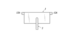
- FIG. 1 is a schematic view showing a cleaning tool according to Embodiment 1.
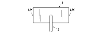
- FIG. 6 is a schematic view showing a cleaning tool according to Embodiment 2.
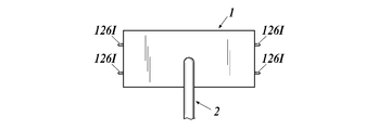
- FIG. 6 is a schematic view showing a cleaning tool according to Embodiment 3.
- FIG. It is the schematic which shows the cleaning tool which concerns on the comparative example 1. It is a figure which shows a part of cleaning sheet used by the Example and the comparative example.
- FIGS. 1-13 the specific aspect of the cleaning tool 100 which is embodiment of this invention is demonstrated based on FIGS. 1-13.
- the technical scope of the present invention is not limited to the illustrated examples.
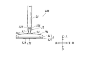
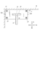
- the description will be given with the X axis, the Y axis, the Z axis, the front-rear direction, the left-right direction, and the up-down direction as shown in FIG.
- the top view in FIG. 1 is a plan view
- the bottom view is a bottom view
- the front view is a front view
- the right or left view is a side view. .
- the cleaning tool 100 includes a head part 1 to which the cleaning sheet P is attached, a handle part 2 for a user to hold the cleaning tool 100, and a joint part 3 that connects the head part 1 and the handle part 2 to each other. ing.
- the head portion 1 is composed of a top surface portion 11 and a bottom surface portion 12 made of different materials, and the joint portion 3 is formed at a substantially central portion of the top surface of the top surface portion 11.
- the handle 2 is attached via
- the top surface portion 11 is a member that has a size of 50 mm to 150 mm in the X axis direction, preferably 70 mm to 120 mm, 200 mm to 300 mm in the Y axis direction, preferably 220 mm to 270 mm, and is substantially rectangular in plan view and long in the Y axis direction.
- it is made of a hard material such as ABS resin (acrylonitrile, butadiene, styrene copolymer synthetic resin).
- ABS resin acrylonitrile, butadiene, styrene copolymer synthetic resin
- the top surface side of the top surface portion 11 is formed so that the vicinity of both ends in the Y-axis direction is high and the vicinity of the center portion in the Y-axis direction is low.
- a sedimentation portion 112 is formed near the center in the Y-axis direction.
- the lower surface side of the top surface portion 11 is formed to be a flat surface and is attached to the upper surface side of the
- the raised portion 111 is formed so as to rise upward in the vicinity of both ends in the Y-axis direction on the upper surface side of the top surface portion 11 in a front view. Further, as shown in FIG. 3, the raised portion 111 is highest in the vicinity of the central portion in the X-axis direction in a side view, and is formed so as to protrude gently from the front-rear direction to the vicinity of the central portion in the X-axis direction.
- the raised portion 111 is formed so that the thickness of the head portion 1 is 10 mm to 30 mm, preferably 15 mm to 25 mm, at the highest portion. If the thickness of the head portion 1 is lower than 10 mm, the finger may not be easily inserted when the sheet is attached to the mounting portion 13 described later, and the sheet may be easily removed. It becomes difficult to enter the lower side of furniture with low height.
- the specific arrangement position and shape of the raised portion 111 are not limited to those described above, and can be appropriately changed within a range in which the handle portion 2 can be lifted when getting over the first protruding portion 311. It is. Further, the raised portion 111 is preferably formed in the vicinity of both end portions in the longitudinal direction in the plan view of the head portion 1, but is not limited to this, and two first protrusion portions 311 of the first yoke portion 31 described later are provided. It suffices if it is formed in the vicinity of both ends in the same direction as the arrangement direction.
- the settling portion 112 is formed so as to gently sink from the raised portions 111 formed at both ends in the vicinity of the central portion in the Y-axis direction on the upper surface side of the top surface portion 11.
- the sinking portion 112 is formed so that the thickness of the head portion 1 is 15 mm or less, preferably 12 mm or less, in the central portion of the top surface portion 11 to which the handle portion 2 is attached via the joint portion 3.
- the bottom surface portion 12 is made of a material that is soft and elastically deformable compared to the top surface portion 11 such as TPE (thermoplastic elastomer). It is formed so as to have a congruent substantially rectangular shape.
- the thickness is 1 mm to 10 mm, preferably 3 mm to 4 mm in the Z-axis direction.
- the rubber hardness of the material used is preferably 60 to 100 (value measured by durometer type A (Shore A) defined by JIS K 6253) from the viewpoint of dust collection.
- the bottom surface portion 12 is formed so that the upper surface side and the lower surface side are substantially parallel to each other, and is attached to the top surface portion 11 on the upper surface side.
- a flat surface portion 121, a short-side concave portion 122, and a long-side concave portion 123 are formed on the bottom surface side of the bottom surface portion 12.
- the flat surface portion 121 is substantially flat except for a later-described linear rib 124 that constitutes a portion other than the short-side concave portion 122 and the long-side concave portion 123 on the lower surface side of the bottom surface portion 12. It is a formed part.
- the bottom surface portion 12 refers to the entire member formed of an elastically deformable material constituting the lower side of the head portion 1, and the flat surface portion 121 is formed on a substantially flat surface of the bottom surface of the bottom surface portion 12. Refers to the part.
- the short-side concave portion 122 is concave toward the upper side formed in the vicinity of both ends in the short-side direction (X-axis direction) on the lower surface side of the bottom surface portion 12. It is a formed part.
- the cleaning tool 100 when used, the vicinity of both ends in the short side direction (X-axis direction) on the lower surface side of the head portion 1 is not in close contact with the floor surface, and a gap is formed between the floor surface. Become.
- the short-side concave portion 122 is formed in any shape as long as a gap can be formed between the head portion 1 and the floor surface on the lower surface side in the vicinity of both ends in the short-side direction (X-axis direction). Although it is possible to do so, the lower surface side of the bottom surface portion 12 is formed to be the most recessed at the Y-axis direction central portion of the front or rear end of the head portion 1, and the dent becomes smaller as the distance from the portion decreases. It is desirable that it be formed so as to be gently connected to the flat portion 121.
- the short-side concave portion 122 is formed so as to be recessed upward in the most concave portion in comparison with the plane portion 121 of 0.1 mm to 5 mm, more preferably 0.5 mm to 3 mm.
- the floor surface is cleaned when the cleaning tool 100 is moved in the short-side direction (X-axis direction) of the head portion 1.
- the dust on the surface does not collect at the front and rear end portions of the head portion 1, but is attracted to the lower surface of the head portion 1, thereby improving the collection property of the dust.
- the longitudinal concave portion 123 is formed so as to be concave toward the upper side formed in the vicinity of both ends in the longitudinal direction (Y-axis direction) on the lower surface side of the bottom surface portion 12. Part.
- the cleaning tool 100 when used, the vicinity of both ends in the longitudinal direction (Y-axis direction) on the lower surface side of the head portion 1 does not adhere to the floor surface, and a gap is generated between the floor surface. .
- the longitudinal concave portion 123 is formed in an arbitrary shape as long as a gap can be generated between the head portion 1 and the floor surface on the lower surface side in the vicinity of both end portions in the longitudinal direction (Y-axis direction).
- the lower surface side of the bottom surface portion 12 is formed so as to be recessed most greatly in the X-axis direction central portion of the right or left end portion of the head portion 1, and the recess becomes smaller as the distance from the portion decreases, and the flat surface portion 121. It is desirable that it is formed so as to be connected smoothly.
- the longitudinal concave portion 123 is formed so as to be recessed upward in the most concave portion compared to the plane portion 121 of 0.1 mm to 5 mm, more preferably 0.5 mm to 3 mm.
- the longitudinal concave portion 123 is formed on the lower surface side of the bottom surface portion 12, when the cleaning tool 100 is moved in the longitudinal direction (Y-axis direction) of the head portion 1 to clean the floor surface, The dust is not collected at the left and right end portions of the head portion 1 but is attracted to the lower surface of the head portion 1, so that the collection property of the dust can be improved.
- a linear rib 124 that protrudes downward so as to be linear when viewed from the bottom is formed on the flat surface 121 on the lower surface side of the bottom surface portion 12.
- the linear ribs 124 are all formed so as to have the same height in the Z-axis direction, and specifically, formed so as to protrude downward from 0.1 mm to 2 mm, more preferably from 0.2 mm to 1 mm. Is done.
- Each linear rib is formed in a linear shape having a length of 1 mm to 100 mm, preferably 8 mm to 85 mm, and a width of 0.1 mm to 2 mm, preferably 0.2 mm to 1.2 mm.
- the linear rib 124 includes both a rib formed in a straight line shape in a bottom view and a rib formed in a curved line shape in a bottom view.
- the linear rib 124 includes a diagonal rib 1241 and a rhombus rib 1242, and a specific arrangement is as follows.
- the oblique ribs 1241 are formed on the entire surface of the flat portion 121 except for the portion where the rhombus ribs 1242 are formed. As shown in FIG. 4, the oblique rib 1241 has an X axis toward the Y axis direction central portion from the X axis direction central portion of the head portion 1 bottom surface toward the front or rear in the bottom view of the head portion 1. It is formed in the shape of a line inclined from a direction parallel to the.
- the oblique ribs 1241 are formed symmetrically in the front-rear direction with the center portion in the X-axis direction on the back surface of the head portion 1 as a symmetry axis, and are symmetrical in the left-right direction with the center portion in the Y-axis direction on the back surface in the head portion 1 as a reference axis. Is formed.
- the rhomboid rib 1242 is a portion in which a linear rib is disposed on a substantially rhombus in a bottom view, and among the plane portion 121, a central portion in the X-axis direction and the Y-axis direction, and X
- the center portion in the axial direction is formed at two locations that are intermediate between the center portion and the end portion in the Y-axis direction, and at four locations near the four corners of the lower surface of the head portion 1.
- End rib On the lower surface side in the vicinity of both ends in the longitudinal direction (Y-axis direction) on the lower surface side of the bottom surface portion 12, an end rib 125 formed linearly along the Y-axis direction is formed at the center portion in the X-axis direction. Yes.
- the end ribs 125 are formed so as to have a height of 1 mm to 5 mm in the downward direction when viewed from the plane part 121. If it is lower than 1 mm, the groove cannot be sufficiently cleaned, and if it is higher than 5 mm, there is a high possibility that it will become an obstacle when cleaning the flat portion of the floor surface. However, the end rib 125 needs to be formed so as to be higher than the linear rib 124 in the Z-axis direction.
- the end rib 125 is formed so as to have the above-mentioned height with respect to the plane portion 121. Need to be done. Further, the end rib 125 has a length in the Y axis direction of 10 mm to 50 mm, more preferably 20 mm to 30 mm, and a width in the X axis direction of 0.1 mm to 3 mm, more preferably 0.5 mm to 1.5 mm. It is formed.
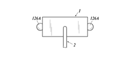
- End protrusion As shown in FIGS. 1, 2, and 4, the center portion in the X-axis direction of both end portions in the longitudinal direction (Y-axis direction) of the head portion 1 is continuous with the end rib 125, and thus in the Y-axis direction. An end protrusion 126 that protrudes toward the center is formed. The end protrusions 126 are formed so as to protrude rightward or leftward by 0.5 mm to 3 mm, more preferably 0.8 mm to 2 mm from both ends in the longitudinal direction (Y-axis direction) of the head portion 1. .
- the end protrusion 126 is made of the same material as that for forming the bottom surface portion 12. 1, 2, and 4, the case where the end protrusions 126 are formed on one side of each side of the head portion 1 is illustrated, but a larger number of end protrusions 126 are provided. It may be done.
- mounting portions 13 are provided in the vicinity of the four corners in plan view of the upper surface of the top surface portion 11.
- the attachment portion 13 is a hole formed on the raised portion 111 on the top surface portion 11 and provided with a claw portion 131 formed of EVA (ethylene vinyl acetate copolymer) or the like around it.
- EVA ethylene vinyl acetate copolymer
- the cleaning sheet P can be attached to the head portion 1 by being hooked on the pushing claw portion 131. Specifically, the cleaning sheet P is brought into close contact with the lower surface side of the bottom surface portion 12, and the portion of the cleaning sheet P protruding from the lower surface side of the bottom surface portion 12 is folded back to the upper surface side of the top surface portion 11.
- the cleaning sheet P is attached to the head portion 1 by being pushed into the provided attachment portion 13.
- the shape of the attachment part 13 should just be able to attach the cleaning sheet P to the head part 1, and is not restricted to said shape.
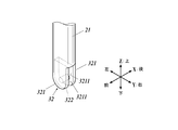
- the handle part 2 is a rod-shaped member used for a user to hold when using the cleaning tool 100, and includes a handle body 21 and a holding part 22 as shown in FIG. 1.
- the handle portion 2 is pivotally connected to the head portion 1 via the joint portion 3.
- the handle portion 2 stands vertically on the head portion 1 in the front-rear direction and the left-right direction. The description will be given with the vertical direction determined.
- the handle body 21 is a rod-shaped member formed of a hard material such as ABS resin (acrylonitrile, butadiene, styrene copolymer synthetic resin), and the top surface portion of the head portion 1 at the lower end. 11 is connected to a substantially central portion on the upper surface side via the joint portion 3 and is connected to the grip portion 22 at the upper end portion.
- the handle body 21 is formed in the vicinity of the lower end so that the thickness in the front-rear direction is thinner than the thickness in the left-right direction. As a result, the handle 2 can be easily lowered to a low state.
- the vicinity of the lower end of the handle body 21 may be formed to have the same thickness in the front-rear direction and the left-right direction. Further, for example, the strength of the second protrusion 321 described later may be emphasized, and the thickness in the front-rear direction may be greater than the thickness in the left-right direction.
- the grip portion 22 is a member that the user grips when using the cleaning tool 100, and is formed of a soft material as compared with the handle body 21 such as polypropylene or polyacetal, and has a lower end portion as shown in FIG. , Connected to the handle body 21.
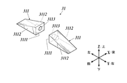
- the joint portion 3 is provided at a first yoke portion 31 provided at a substantially central portion on the upper surface side of the top surface portion 11 of the head portion 1 and a lower end portion of the handle portion 2.
- the second yoke portion 32, the first yoke portion 31, and the connecting portion 33 that connects the second yoke portion 32 are formed.
- the first yoke portion 31 is formed integrally with the top surface portion 11 in the central portion on the upper surface side of the top surface portion 11 of the head portion 1. It is formed by two symmetrical first protrusions 311 facing each other at the surface portion 3111. In the present embodiment, a portion formed by providing two symmetrical protrusions and used for connection with another member is referred to as a “yoke portion”.
- the first protruding portion 311 is gradually increased toward the first facing surface portion 3111 where the first protruding portions 311 face each other when viewed from the X-axis direction. Are formed so as to increase in height and are arranged along the Y axis.
- the first protrusion 311 is formed to be 5 mm to 20 mm in the X axis direction, preferably 8 mm to 15 mm, and 10 mm to 50 mm, preferably 15 mm to 30 mm in the Y axis direction. Further, in the vicinity of the highest first facing surface portion 3111, it is 5 mm to 15 mm, preferably 8 mm to 12 mm in the Z-axis direction, and is formed to be equal or higher than the raised portion 111.
- the first protrusions 311 are arranged so that the first facing surface portions 3111 have a distance of 10 mm to 25 mm, preferably 15 mm to 20 mm.
- the first facing surface portion 3111 is a surface where the first protrusions 311 face each other, and is formed in a substantially rectangular shape that stands substantially vertically from the upper surface side of the top surface portion 11.
- the first opposing surface portions 3111 are formed to be parallel to each other.
- a hole 3113 is formed in the first facing surface portion 3111.
- the hole 3113 is a cylindrical hole formed in the first facing surface portion 3111, and is used for connection with the first rotation axis portion 331 of the connecting portion 33 as described later.
- the side surface portion 3112 has an X-axis direction parallel to the YZ plane of the first projection portion 311 formed continuously from the front and rear sides of the first facing surface portion 3111.
- the head surface 1 is formed so as to stand substantially vertically from the upper surface side of the top surface portion 11 of the head portion 1.
- the second yoke portion 32 has two symmetrical second shapes extending in the axial direction at the lower end portion of the handle body 21 of the handle portion 2.
- the protrusion 321 and the second shaft member 322 spanned between the second opposing surface portions 3211 of the second protrusion 321 are formed.
- the second projecting portion 321 has second opposing surface portions 3211 facing each other in parallel at both ends in the X-axis direction in the state shown in FIG. Thus, it is formed integrally with the handle body 21.
- the second protrusion 321 has a thickness of 2 mm to 6 mm, preferably 3 mm to 5 mm in the X-axis direction, and substantially the same width as the handle body 21 in the Y-axis direction. If the thickness in the X-axis direction is too thin, it will be insufficient in strength when pressed during cleaning and will likely be damaged. If it is too thick, the handle will interfere with the top surface of the head when tilted in the X-axis direction and tilted to approximately parallel. It becomes difficult.
- the second opposing surface portions 3211 are formed so as to have an interval of 2 mm to 10 mm, preferably 3 mm to 7 mm.
- the second shaft member 322 is formed integrally with the second projecting portion 321 so as to bridge between the second facing surface portions 3211 along the X axis at the center portion in the Y axis direction. ing.
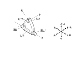
- the connecting portion 33 is provided between the first yoke portion 31 and the second yoke portion 32.
- a first rotation shaft center portion 331 and a second rotation shaft center portion 332 which are formed in a substantially triangular shape as viewed and are orthogonal to each other without intersecting the central axes in a three-dimensional crossing manner are provided.
- a polyacetate is used, for example.
- the first rotation shaft center portion 331 is a portion formed at the lower end portion of the coupling portion 33 and used for connection with the first yoke portion 31, and at both ends in the Y-axis direction, A cylindrical protrusion 3311 is provided.
- the width of the first rotating shaft center portion 331 in the Y-axis direction except for the protruding portion 3311 is substantially the same as the interval between the first opposing surface portions 3111 of the first protruding portion 311, and the protruding portion 3311 is
- the hole 3113 has substantially the same shape.
- the connecting portion 33 can be attached to the first yoke portion 31 so as to be rotatable around the Y axis.
- a central axis along the Y axis of the first rotation axis part 331 shown in FIG. 7 is defined as a first axis a.
- the second rotation axis part 332 is a part formed at the upper end part of the connecting part 33 and used for connection with the second yoke part 32, and a part of the upper end part is cut. It has a substantially cylindrical second mounting hole 3321 that is cut out and penetrates in the front-rear direction. The diameter of the cylindrical space formed inside the second mounting hole 3321 is substantially the same as the diameter of the second shaft member 322.
- the length in the X-axis direction is formed to be substantially the same as the length of the second shaft member 322, and the second shaft member 322 is fitted into the second mounting hole 3321 so that the connecting portion 33 can be fixed to the second yoke portion 32 so as to be rotatable around the X axis.
- the end protrusion does not necessarily have to be continuously provided with the end rib, and any shape and arrangement can be used as long as it protrudes from the end of the head portion in plan view. .
- the end protrusions may be formed on either the upper or lower side of the side surface of the head unit 1, and even if the end protrusions are formed so as to rise upward or downward, they protrude only in the horizontal direction from the side surface. You may do it. It is also possible to form a gap in the end protrusion.
- the end protrusions only have to be provided so as to be arranged on two opposing sides in the plan view of the rectangular head unit 1, and are not necessarily provided at both ends in the longitudinal direction in the plan view of the head unit 1. It is not necessary to be provided in the central part. For example, it may be arranged at a position deviated from the center of both ends in the longitudinal direction, and may be provided at both ends in the short direction. Moreover, you may provide in the both ends of both a longitudinal direction and a transversal direction. Further, the end protrusions are not limited to being provided at one position on each side in the plan view of the head unit 1, and more end protrusions may be provided. Moreover, about a structure other than an edge part projection part, a various change is possible in the range which can function as a cleaning tool.
- a spherical end protrusion 126 ⁇ / b> A can be provided in the central portion in plan view of the end of the head portion 1. At this time, it is desirable to determine the diameter of the spherical end protrusion 126A so that the end protrusion A protrudes 2 mm below the flat surface 121 on the bottom surface of the bottom surface 12. Further, as in the end protrusion 126B shown in FIG. 9C, a gap may be provided to provide cushioning properties.
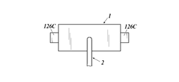
- a rectangular parallelepiped end protrusion 126 ⁇ / b> C can be provided below the center of the end of the head portion 1 in plan view.
- a rectangular parallelepiped end protrusion 126 ⁇ / b> D may be provided above the center of the end of the head portion 1 in plan view.
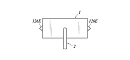
- a triangular pyramid-shaped end protrusion 126 ⁇ / b> E can be provided on the lower side of the center of the end of the head 1 in plan view.
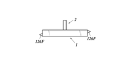
- a triangular pyramid-shaped end protrusion 126F can be provided in the central portion in plan view of the end of the head portion 1, one on the upper side and the other on the lower side.
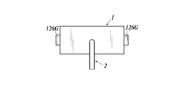
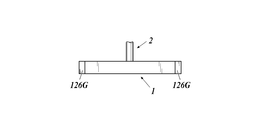
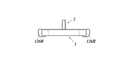
- an end protrusion 126G is provided at the center of the end of the head 1 so as to cover the entire height of the end of the head 1 in the vertical direction. Is also possible. Further, as shown in FIG. 12C, the end protrusion 126H may be formed so as to enter the lower surface side of the head portion 1 and protrude to the upper surface side.
- the end protrusions can be arranged as shown in FIGS. 13A to 13C, and can be arranged at arbitrary positions on two sides facing each other in plan view.
- the end protrusions can be formed in any shape and position as long as the above functions can be achieved.
- the top surface portion is formed in a rectangular shape in a plan view having a long side of 240 mm and a short side of 95 mm using ABS resin
- the bottom surface portion is formed in a plan view of a long side of 248 mm and a short side of 98 mm using an elastomer (TPE) having a hardness of 70 °. It was formed in a rectangular shape.
- the handle portion was formed so that the length from the connecting portion with the head portion to the upper end of the grip portion was 215 mm.
- the lower surface side of the bottom surface portion of the cleaning tool as described above was formed as shown in FIG. Specifically, it is as follows.
- the linear rib has a height of 0.3 mm and a width of 1 mm
- the oblique rib has a curved shape with a length of 10 mm to 80 mm
- the diamond-shaped rib has a large size of 50 mm in the X-axis direction and 28 mm in the Y-axis direction.
- the small size is 14 mm in the X-axis direction and 11 mm in the Y-axis direction.
- the diagonal ribs are arranged so that the arrangement interval is 6 mm at the narrowest position and 9 mm at the widest position, and the four rhombus ribs are arranged at a position 10 m diagonally from the four corners, one at the center and one at the center.
- the end protrusion 126 has a height of 2 mm downward from the flat surface of the bottom surface of the bottom surface at the center of the left and right short sides of the head portion. It was formed to protrude 1.5 mm to the left or to the left. The end protrusion 126 is formed so as to protrude left and right in parallel with the long side of the head portion.
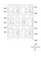
- a dry sheet formed into a rectangular shape having a long side of 300 mm and a short side of 200 mm and embossed with a basis weight of 100 gsm was used. Specifically, as shown in FIG.
- a convex emboss EM1 that is convex on the upper surface side of the sheet and a concave emboss EM2 that is convex on the lower surface side of the sheet are alternately arranged in the X-axis direction and the Y-axis direction. What was formed so that it might be arrange
- positioned was used. Specifically, the embossing was formed such that the long side direction was 8 mm, the short side direction was 3 mm, and the height was 0.8 mm. The direction in which the emboss becomes longer in plan view, that is, the X-axis direction in FIG.
- the nonwoven fabric which has a polyethylene terephthalate as a main component was used for the hydrophobic fiber of a cleaning sheet outer layer
- the fiber which has a polypropylene as a main component was used for the hydrophobic fiber of a cleaning sheet inner layer.
- chemical fibers mainly composed of polyethylene terephthalate, polypropylene, polyethylene or the like are applied.
- the outer layer is composed of 100% hydrophobic fiber, 80% polyethylene terephthalate is contained as the hydrophobic fiber, and 20% polypropylene-polyethylene core-sheath fiber is contained as the binder fiber.
- polyethylene terephthalate fibers having a fineness of 3.3 dtex and binder fibers having a fineness of 1.7 dtex were used.
- the inner layer is made of a 100% polypropylene spunbond nonwoven fabric. By the hydroentanglement, the inner layer and the outer layer are combined to form a spunlace nonwoven fabric having a three-layer structure. In the present embodiment, a dry sheet is used, but a wet sheet can also be used.
- the cleaning tool is provided with an end protrusion 126I.
- the end protrusion 126I has a height of 2 mm downward from the flat surface of the bottom surface of the bottom surface at two locations on each of the left and right short sides of the head portion. 1 mm so as to protrude 1 mm. Further, the end protrusion 126I was formed so as to protrude left and right in parallel with the long side of the head portion. Other configurations are the same as those of the first embodiment.
- the end protrusion 126J is a triangle in which one side is parallel to the long side of the head part in plan view and one side is at an angle of 45 ° with the long side of the head part in plan view in each of two left and right short sides of the head part.
- Two protrusions formed in a shape were formed so as to face each other at an angle of 45 °. Accordingly, protrusions are formed in a total of eight places.
- Each of the protrusions of the end protrusion 126J has a height of 2 mm downward from the flat surface of the bottom surface of the bottom surface, and a side having a 45 ° angle with the long side of the head portion in plan view is 1.0 mm. It was formed to be a length of. Other configurations are the same as those of the first embodiment.
- FIG. 14D it is a cleaning tool which is not provided with the edge part projection part.
- Other configurations are the same as those of the first embodiment.
- a cleaning sheet was attached to the cleaning tools of the above Examples and Comparative Examples, and the subjects were allowed to clean the flooring surface that had been sprinkled with trash, and the sensory evaluation was performed on the dust collection property near the corner of the room.
- the present invention can be suitably used in the field of manufacturing a cleaning tool.
Landscapes
- Cleaning Implements For Floors, Carpets, Furniture, Walls, And The Like (AREA)
Applications Claiming Priority (2)
| Application Number | Priority Date | Filing Date | Title |
|---|---|---|---|
| JP2017-117127 | 2017-06-14 | ||
| JP2017117127A JP6563980B2 (ja) | 2017-06-14 | 2017-06-14 | 掃除具 |
Publications (1)
| Publication Number | Publication Date |
|---|---|
| WO2018230292A1 true WO2018230292A1 (ja) | 2018-12-20 |
Family
ID=64659070
Family Applications (1)
| Application Number | Title | Priority Date | Filing Date |
|---|---|---|---|
| PCT/JP2018/019927 Ceased WO2018230292A1 (ja) | 2017-06-14 | 2018-05-24 | 掃除具 |
Country Status (2)
| Country | Link |
|---|---|
| JP (1) | JP6563980B2 (enExample) |
| WO (1) | WO2018230292A1 (enExample) |
Cited By (3)
| Publication number | Priority date | Publication date | Assignee | Title |
|---|---|---|---|---|
| CN113840563A (zh) * | 2019-05-17 | 2021-12-24 | 尤妮佳股份有限公司 | 清扫工具 |
| US11317781B2 (en) * | 2017-06-14 | 2022-05-03 | Daio Paper Corporation | Cleaning tool |
| WO2025163930A1 (ja) * | 2023-02-17 | 2025-08-07 | 株式会社コーワ | 清掃具 |
Citations (3)
| Publication number | Priority date | Publication date | Assignee | Title |
|---|---|---|---|---|
| JP3019135U (ja) * | 1995-06-09 | 1995-12-12 | アイリスオーヤマ株式会社 | 清掃用具 |
| JP2003111709A (ja) * | 2001-10-05 | 2003-04-15 | Yamazaki Corp | 清掃用器具 |
| JP2017042181A (ja) * | 2015-08-24 | 2017-03-02 | 株式会社無有 | 清掃用具 |
Family Cites Families (7)
| Publication number | Priority date | Publication date | Assignee | Title |
|---|---|---|---|---|
| JP2002010960A (ja) * | 2000-06-29 | 2002-01-15 | Koowa:Kk | 床用掃除具 |
| KR200340927Y1 (ko) * | 2003-10-15 | 2004-02-11 | 김하나 | 걸레 청소 도구 |
| US8464391B2 (en) * | 2007-04-03 | 2013-06-18 | Diversey, Inc. | Mop head fixation device and method |
| KR100802464B1 (ko) * | 2007-04-16 | 2008-02-13 | 주식회사 리빙휴 | 자루걸레 |
| JP5190314B2 (ja) * | 2008-07-25 | 2013-04-24 | 花王株式会社 | 清掃具 |
| US8640296B2 (en) * | 2010-01-11 | 2014-02-04 | Quickie Manufacturing Corporation | Adjustable cleaning head for a cleaning tool |
| KR200473432Y1 (ko) * | 2013-07-15 | 2014-07-04 | 주식회사 우일 | 대걸레용 밀대 |
-
2017
- 2017-06-14 JP JP2017117127A patent/JP6563980B2/ja active Active
-
2018
- 2018-05-24 WO PCT/JP2018/019927 patent/WO2018230292A1/ja not_active Ceased
Patent Citations (3)
| Publication number | Priority date | Publication date | Assignee | Title |
|---|---|---|---|---|
| JP3019135U (ja) * | 1995-06-09 | 1995-12-12 | アイリスオーヤマ株式会社 | 清掃用具 |
| JP2003111709A (ja) * | 2001-10-05 | 2003-04-15 | Yamazaki Corp | 清掃用器具 |
| JP2017042181A (ja) * | 2015-08-24 | 2017-03-02 | 株式会社無有 | 清掃用具 |
Cited By (3)
| Publication number | Priority date | Publication date | Assignee | Title |
|---|---|---|---|---|
| US11317781B2 (en) * | 2017-06-14 | 2022-05-03 | Daio Paper Corporation | Cleaning tool |
| CN113840563A (zh) * | 2019-05-17 | 2021-12-24 | 尤妮佳股份有限公司 | 清扫工具 |
| WO2025163930A1 (ja) * | 2023-02-17 | 2025-08-07 | 株式会社コーワ | 清掃具 |
Also Published As
| Publication number | Publication date |
|---|---|
| JP2019000333A (ja) | 2019-01-10 |
| JP6563980B2 (ja) | 2019-08-21 |
Similar Documents
| Publication | Publication Date | Title |
|---|---|---|
| US9408518B2 (en) | Retainers for a device having removable floor sheets | |
| JP6563980B2 (ja) | 掃除具 | |
| JP2981110B2 (ja) | 清掃用具 | |
| JP6271479B2 (ja) | 清掃用具 | |
| JP6571132B2 (ja) | 掃除具 | |
| JP6491695B2 (ja) | 掃除具 | |
| JP2018068780A5 (enExample) | ||
| EP3520669B1 (en) | Cleaning head and cleaning tool | |
| JP7407612B2 (ja) | 清掃用治具 | |
| WO2018235514A1 (ja) | 掃除具 | |
| JP6524168B2 (ja) | 掃除具 | |
| JP3129712U (ja) | 床面用モップ式清掃用具 | |
| JP2004033530A (ja) | 清掃用具 | |
| JP7185442B2 (ja) | 清掃用具 | |
| JP6297831B2 (ja) | 清掃シート及びこれを有する清掃用具 | |
| JP6526762B2 (ja) | 掃除具 | |
| JP7185443B2 (ja) | 清掃用具 | |
| EP3024373B1 (en) | Retainers for a device having removable floor sheets | |
| JP2020188823A (ja) | 清掃具 | |
| WO2025041529A1 (ja) | 清掃用部材、清掃用具 |
Legal Events
| Date | Code | Title | Description |
|---|---|---|---|
| 121 | Ep: the epo has been informed by wipo that ep was designated in this application |
Ref document number: 18817126 Country of ref document: EP Kind code of ref document: A1 |
|
| NENP | Non-entry into the national phase |
Ref country code: DE |
|
| 122 | Ep: pct application non-entry in european phase |
Ref document number: 18817126 Country of ref document: EP Kind code of ref document: A1 |