WO2018229902A1 - 筐体、電子機器、冷却方法 - Google Patents
筐体、電子機器、冷却方法 Download PDFInfo
- Publication number
- WO2018229902A1 WO2018229902A1 PCT/JP2017/021978 JP2017021978W WO2018229902A1 WO 2018229902 A1 WO2018229902 A1 WO 2018229902A1 JP 2017021978 W JP2017021978 W JP 2017021978W WO 2018229902 A1 WO2018229902 A1 WO 2018229902A1
- Authority
- WO
- WIPO (PCT)
- Prior art keywords
- partition wall
- top plate
- hole
- cylindrical body
- heating element
- Prior art date
- Legal status (The legal status is an assumption and is not a legal conclusion. Google has not performed a legal analysis and makes no representation as to the accuracy of the status listed.)
- Ceased
Links
Images





Classifications
-
- H—ELECTRICITY
- H05—ELECTRIC TECHNIQUES NOT OTHERWISE PROVIDED FOR
- H05K—PRINTED CIRCUITS; CASINGS OR CONSTRUCTIONAL DETAILS OF ELECTRIC APPARATUS; MANUFACTURE OF ASSEMBLAGES OF ELECTRICAL COMPONENTS
- H05K7/00—Constructional details common to different types of electric apparatus
- H05K7/20—Modifications to facilitate cooling, ventilating, or heating
- H05K7/20009—Modifications to facilitate cooling, ventilating, or heating using a gaseous coolant in electronic enclosures
- H05K7/20127—Natural convection
-
- H—ELECTRICITY
- H05—ELECTRIC TECHNIQUES NOT OTHERWISE PROVIDED FOR
- H05K—PRINTED CIRCUITS; CASINGS OR CONSTRUCTIONAL DETAILS OF ELECTRIC APPARATUS; MANUFACTURE OF ASSEMBLAGES OF ELECTRICAL COMPONENTS
- H05K5/00—Casings, cabinets or drawers for electric apparatus
- H05K5/02—Details
- H05K5/0213—Venting apertures; Constructional details thereof
-
- H—ELECTRICITY
- H05—ELECTRIC TECHNIQUES NOT OTHERWISE PROVIDED FOR
- H05K—PRINTED CIRCUITS; CASINGS OR CONSTRUCTIONAL DETAILS OF ELECTRIC APPARATUS; MANUFACTURE OF ASSEMBLAGES OF ELECTRICAL COMPONENTS
- H05K7/00—Constructional details common to different types of electric apparatus
- H05K7/20—Modifications to facilitate cooling, ventilating, or heating
- H05K7/2089—Modifications to facilitate cooling, ventilating, or heating for power electronics, e.g. for inverters for controlling motor
- H05K7/20909—Forced ventilation, e.g. on heat dissipaters coupled to components
Definitions
- the present invention relates to a housing, an electronic device, and a cooling method.
- Patent Document 1 discloses a technique related to heat dissipation measures for a housing in which a heating element such as a power IC is accommodated. Specifically, an upper ventilation hole and a lower ventilation hole are formed in each of the top plate portion and the bottom plate portion of the housing. With this configuration, an air flow is formed from the lower side to the upper side facing the space in the vicinity of the heating element.
- the top plate portion of the housing may locally become hot.
- an object of the present invention is to provide a technique for suppressing the top plate from locally becoming high temperature in a configuration in which the top plate of the housing has a vent hole.
- a casing that includes a cylindrical body that extends vertically and a top plate that is disposed at an upper end of the cylindrical body and can accommodate a heating element.
- the top plate is formed with a vent hole for discharging the air heated by the heating element to the outside. Between the vent hole and the cylindrical body, the vent plate is formed downward from the top plate.
- a housing provided with a protruding partition wall, in which an air reservoir part surrounded by the cylindrical body, the top plate, and the partition wall is formed.
- the present invention provides a cooling method for a housing that includes, as a second aspect, a vertically extending cylindrical body, and a top plate disposed at an upper end of the cylindrical body, and is capable of accommodating a heating element, A vent hole for discharging the air heated by the heating element to the outside is formed in the top plate, and a partition wall protruding downward from the top plate is provided between the vent hole and the cylindrical body, Provided is a cooling method for forming an air reservoir surrounded by a cylinder, the top plate, and the partition.
- the present invention in the configuration in which the top plate of the housing has the vent holes, it is possible to suppress the top plate from being locally heated.
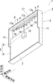
- FIG. 1 is a perspective view of the electronic device 1. 2 to FIG. 4 are partially cutaway perspective views of the electronic device 1.
- FIG. 5 shows a front sectional view of the electronic device 1.
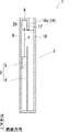
- FIG. 6 shows a side cross-sectional view of the electronic apparatus 1.
- the electronic device 1 includes a housing 2 and an electronic device body 3.
- the electronic device main body 3 includes a wiring board 4 and a heating element 5.
- the housing 2 is formed in a rectangular box shape. That is, the casing 2 includes a rectangular tubular body 6 extending vertically, a rectangular bottom plate 7 disposed at the lower end of the tubular body 6, and a rectangular top plate 8 disposed at the upper end of the tubular body 6. And having.
- the rectangular tubular cylinder 6 has four side plates. That is, the rectangular tubular body 6 includes a front panel 9 (front side plate), a back panel 10 (back side plate), and two side panels 11 (side plate) facing each other. .
- a direction in which the front panel 9 and the rear panel 10 face each other is referred to as a “front-rear direction”.
- a direction in which the front panel 9 is viewed from the rear panel 10 in the front-rear direction is referred to as “front”
- a direction in which the rear panel 10 is viewed from the front panel 9 is referred to as “rear”.
- a direction in which the two side panels 11 face each other is referred to as a “width direction”.
- the direction in which the bottom plate 7 and the top plate 8 face each other is referred to as “vertical direction”.
- a direction in which the top plate 8 is viewed from the bottom plate 7 in the vertical direction is referred to as “upward”, and a direction in which the bottom plate 7 is viewed from the top plate 8 is referred to as “downward”.
- “Front end” and “rear end” mean “front end” and “rear end”, respectively.
- “Upper end” and “lower end” mean “upper end” and “lower end”, respectively.
- the front-rear direction, the width direction, and the up-down direction are orthogonal to each other.
- the housing 2 is configured to be flat in the front-rear direction. That is, the dimension of the casing 2 in the front-rear direction is smaller than the dimension of the casing 2 in the width direction.
- the housing 2 accommodates the electronic device main body 3.
- the wiring board 4 is configured in a thin plate shape in which the plate thickness direction is parallel to the front-rear direction.
- the wiring board 4 is disposed so as to contact the bottom plate 7 and the two side panels 11.
- the wiring board 4 is arranged away from the top plate 8. That is, there is a gap between the wiring board 4 and the top plate 8.
- the heating element 5 is mounted on the component mounting surface 4 a of the wiring board 4.
- the heating element 5 is disposed at the center in the width direction of the wiring board 4.
- the component mounting surface 4a is a surface facing forward. Examples of the heating element 5 include a power semiconductor that generates a large amount of heat.
- the side vent hole 15 is formed in the two side panels 11, respectively.
- the side air holes 15 are formed in front of the component mounting surface 4 a of the wiring board 4. Therefore, the outside air taken in from the side vent hole 15 can be directly supplied to the heating element 5.
- the housing 2 further includes an upper ventilation hole 16 (a ventilation hole), a partition wall 17, and a plurality of reinforcing ribs 18.
- the upper vent 16 is a vent for discharging the air heated by the heating element 5 to the outside, and is formed in the top plate 8.
- the upper ventilation hole 16 penetrates the top plate 8 in the vertical direction.
- the upper vent 16 is formed closer to the back panel 10.
- the upper vent 16 is constituted by a plurality of upper through holes 16a arranged at equal intervals in the width direction. That is, the upper ventilation hole 16 is divided by a plurality of reinforcing ribs 18.
- the plurality of reinforcing ribs 18 can be omitted. When the plurality of reinforcing ribs 18 are omitted, the upper ventilation hole 16 is formed so as to be elongated in the width direction.
- the partition wall 17 and the plurality of reinforcing ribs 18 are disposed inside the cylindrical body 6.
- the partition wall 17 is formed so as to protrude downward from the top plate 8.
- the partition wall 17 is configured in a flat plate shape whose plate thickness direction is parallel to the front-rear direction.
- the partition wall 17 is disposed between the upper ventilation hole 16 and the front panel 9.
- the partition wall 17 is arranged rearward from the front panel 9.
- the partition wall 17 is disposed away from the back panel 10 in the forward direction.
- the partition wall 17 when the partition wall 17 is viewed in the plate thickness direction, the lower end 19 of the partition wall 17 is inclined in a V shape so that it is the lowest at the center in the width direction and becomes higher as the distance from the center in the width direction increases.
- the partition wall 17 includes a partition wall low portion 17a (first partition wall portion) in which the distance from the top plate 8 to the lower end 19 of the partition wall 17 is the first distance D1, and the top plate 8 to the lower end 19 of the partition wall 17.
- a partition height portion 17b (second partition portion) whose distance is the second distance D2.
- the second distance D2 is longer than the first distance D1.
- the partition high portion 17b is a central portion in the width direction of the partition wall 17, the partition high portion 17b is different from the heat generating element 5 arranged in the center in the width direction of the wiring substrate 4 in the partition low portion 17a. Is located closer than. That is, when the partition wall 17 is viewed in the thickness direction, the partition wall height portion 17 b is located immediately above the heating element 5.
- the partition wall 17 is disposed between the two side panels 11 and extends in the width direction.
- both ends of the partition wall 17 in the width direction are slightly separated from the two side panels 11. This is because the ease of assembling of the housing 2 is considered, and both ends in the width direction of the partition wall 17 may be in contact with the two side panels 11 or may be continuous.
- the plurality of reinforcing ribs 18 are formed from the partition wall 17 to the back panel 10 so as to straddle the upper ventilation hole 16 in the front-rear direction.
- the plurality of reinforcing ribs 18 are arranged at equal intervals in the width direction.
- Each reinforcing rib 18 is disposed so that the plate thickness direction is parallel to the width direction.
- the plurality of reinforcing ribs 18 finely divide the upper air holes 16 in the width direction. Therefore, as described above, the upper vent hole 16 is divided into a plurality of upper through holes 16 a by the plurality of reinforcing ribs 18.
- the heating element 5 when the heating element 5 is energized, as shown in FIG. 6, the air heated by the heating element 5 (hereinafter referred to as heated air P) rises, and the heated air P passes through the front panel. 9, the air reservoir 20 surrounded by the top plate 8 and the partition wall 17. As shown in FIG. 5, the heated air P reaching the air reservoir 20 is separated into two in the width direction by colliding with the top plate 8 and proceeds toward the two side panels 11. The heated air P is cooled by heat exchange with the outside air via the top plate 8 by temporarily staying in the air reservoir 20.
- heated air P the air heated by the heating element 5
- the heating air P is a position sufficiently away from the partition high portion 17b as shown in FIG. As shown in FIG. 2, the partition wall 17 is passed over and discharged from the upper through hole 16a to the outside.
- the heated air P heated by the heating element 5 since the heated air P heated by the heating element 5 once stays in the air reservoir 20, the heat is diffused in the width direction in the air reservoir 20 and the heated air P is diffused after being diffused. Since it discharges
- the first embodiment has been described above, the first embodiment has the following features.
- the housing 2 includes a cylindrical body 6 that extends vertically and a top plate 8 that is disposed at the upper end of the cylindrical body 6, and can accommodate the heating element 5. .
- the top plate 8 is formed with an upper vent hole 16 (vent hole) for discharging heated air P as air heated by the heating element 5 to the outside.
- a partition wall 17 protruding downward from the top plate 8 is provided between the upper ventilation hole 16 and the cylinder body 6.
- An air reservoir 20 surrounded by the cylindrical body 6, the top plate 8 and the partition wall 17 is formed.
- the heated air P stays in the air reservoir 20 and then passes over the partition wall 17 and is discharged from the upper vent hole 16, it is compared with the case where the heated air P is directly discharged from the upper vent hole 16. And it can suppress that the top plate 8 becomes high temperature locally by the effect of thermal diffusion.
- the cylindrical body 6 is formed in a rectangular cylindrical shape.
- the cylinder 6 may be configured in a cylindrical shape.
- the partition 17 is comprised by flat form.
- the partition wall 17 may be configured in a curved shape.
- the partition wall 17 may be configured in a cylindrical shape surrounding the upper vent hole 16.
- the housing 2 is provided with a plurality of reinforcing ribs 18 extending from the partition wall 17 to the cylinder body 6 so as to straddle the upper ventilation hole 16.
- a plurality of reinforcing ribs 18 instead of providing a plurality of reinforcing ribs 18, only one may be provided, two or three may be provided, and at least one is preferably provided.
- the reinforcing ribs 18 can be omitted.
- the partition wall 17 includes a partition wall low portion 17 a (first partition wall portion) having a first distance D 1 from the top plate 8 to the lower end 19 of the partition wall 17, and the top plate 8.
- a partition height portion 17b (second partition portion) having a second distance D2 that is longer than the first distance D1 by a distance to the lower end 19 of the partition wall 17 is provided.
- the lower end 19 of the partition wall 17 is linearly inclined from the partition high part 17b to the partition low part 17a. According to the above configuration, the flow rate of the heated air P discharged from the upper ventilation hole 16 can be made uniform in the width direction. However, instead of this, the lower end 19 of the partition wall 17 may be curvedly inclined from the partition high part 17b to the partition low part 17a.
- the electronic apparatus 1 includes a housing 2 and a heating element 5. As shown in FIG. 5, the partition high portion 17b is located closer to the heating element 5 than the partition low portion 17a. According to the above configuration, it is possible to prevent the heated air P from getting over the partition wall 17 immediately after entering the air reservoir 20, so that the top plate 8 can be more effectively prevented from becoming locally hot. Can be suppressed.
- the cooling method of the casing 2 that includes the cylindrical body 6 that extends vertically and the top plate 8 that is disposed at the upper end of the cylindrical body 6 and that can accommodate the heating element 5 includes heating air P to the top plate 8.
- FIG. 7 is a partially cutaway perspective view of the electronic device 1.
- FIG. 8 shows a side sectional view of the electronic apparatus 1.
- the partition wall 17 is formed with a plurality of partition wall through holes 22 penetrating the partition wall 17 in the front-rear direction.
- the plurality of partition wall through holes 22 are formed at the upper end of the partition wall 17 so as to be aligned at a constant interval in the width direction.
- one partition wall through hole 22 is formed between two reinforcing ribs 18 adjacent in the width direction.
- the opening areas of the plurality of partition wall through-holes 22 differ depending on the distance from each side panel 11. That is, the plurality of partition wall through holes 22 include a partition wall through small hole 22a (second through hole) and a partition wall through large hole 22b (first through hole).
- the opening area of the partition wall through hole 22b is larger than the opening area of the partition wall hole 22a.
- the partition wall 17 has a partition wall through hole 22b and a partition wall through hole 22a having an opening area smaller than the opening area of the partition wall through hole 22b.
- the plurality of partition wall through holes 22 are formed at different positions in the longitudinal direction of the upper end of the partition wall 17. That is, the partition wall through hole 22a and the partition wall through hole 22b are formed at different positions in the width direction.
- the opening area of each partition wall through-hole 22 is set to increase as it approaches each side panel 11.
- the opening area of each partition wall through-hole 22 is set so as to decrease as it approaches the center in the width direction.
- the partition wall through-holes 22a are located closer to the heating element 5 than the partition wall through-holes 22b.
- the route for the heated air P that once stays in the air reservoir 20 to be discharged from the upper vent 16 is in addition to the route over the partition wall 17 to the upper vent 16.
- a route is provided through the partition wall through hole 22 and through the partition wall 17 to the upper vent hole 16. Then, by making the opening areas of the plurality of partition wall through holes 22 different from each other, the flow rate of the route through which the heated air P passes through the partition wall 17 through each partition wall through hole 22 can be adjusted for each partition wall through hole 22. it can. Therefore, the route through which the heated air P once stored in the air reservoir 20 is discharged from the upper vent hole 16 can be diversified, so that the heat diffusion of the heated air P can be realized at a high level.
- the second embodiment has been described above, the second embodiment has the following features.
- the partition wall 17 has a partition wall through hole 22b (first through hole) and a partition wall through hole 22a (first hole) having an opening area smaller than the opening area of the partition wall through hole 22b. 2 through-holes).
- the partition wall through hole 22 b and the partition wall through hole 22 a are formed at different positions in the longitudinal direction of the upper end of the partition wall 17. According to the above configuration, it is easier for the heated air P to pass through the large partition wall through hole 22b than through the small partition wall through hole 22a. Therefore, it becomes possible to freely control the flow of air when the heated air P travels from the air reservoir 20 to the upper vent hole 16.
- the electronic apparatus 1 includes a housing 2 and a heating element 5.
- the partition wall through hole 22a is located closer to the heating element 5 than the partition wall through hole 22b.
- the cylindrical body 6 may be formed in a cylindrical shape
- the upper ventilation hole 16 may be formed at the radial center of the top plate 8
- the partition wall 17 may be formed in an annular shape so as to surround the upper ventilation hole 16.
Landscapes
- Engineering & Computer Science (AREA)
- Microelectronics & Electronic Packaging (AREA)
- Physics & Mathematics (AREA)
- Thermal Sciences (AREA)
- Cooling Or The Like Of Electrical Apparatus (AREA)
Abstract
筐体(2)は、上下に延びる筒体(6)と、筒体(6)の上端に配置された天板(8)と、を備え、発熱素子(5)を収容可能なものである。天板(8)には、発熱素子(5)によって加熱された空気としての加熱空気(P)を外部に排出するための上方通気孔(16)が形成されている。上方通気孔(16)と筒体(6)の間には、天板(8)から下方に突出する隔壁(17)が設けらている。筒体(6)と天板(8)と隔壁(17)によって囲まれた空気溜まり部(20)が形成されている。
Description
本発明は、筐体、電子機器、冷却方法に関する。
特許文献1は、パワーICなどの発熱素子が収容された筐体の放熱対策に関する技術を開示している。具体的には、筐体の天板部及び底板部のそれぞれに、上部通気孔及び下部通気孔が形成されている。この構成により、発熱素子の近傍の空間に対向して下方から上方へ向かう空気流が形成されている。
しかしながら、上記特許文献1の構成では、筐体の天板部が局所的に高温となる虞がある。
そこで、本発明の目的は、筐体の天板に通気孔を有する構成において、天板が局所的に高温となることを抑制する技術を提供することにある。
上記目的を達成するために、本発明は、第1の態様として、上下に延びる筒体と、前記筒体の上端に配置された天板と、を備え、発熱素子を収容可能な筐体であって、前記天板には、前記発熱素子によって加熱された空気を外部に排出するための通気孔が形成されており、前記通気孔と前記筒体の間には、前記天板から下方に突出する隔壁が設けらており、前記筒体と前記天板と前記隔壁によって囲まれた空気溜まり部が形成されている、筐体を提供する。
また、本発明は、第2の態様として、上下に延びる筒体と、前記筒体の上端に配置された天板と、を備え、発熱素子を収容可能な筐体の冷却方法であって、前記天板に、前記発熱素子によって加熱された空気を外部に排出するための通気孔を形成し、前記通気孔と前記筒体の間に、前記天板から下方に突出する隔壁を設け、前記筒体と前記天板と前記隔壁によって囲まれた空気溜まり部を形成する、冷却方法を提供する。
本願発明によれば、筐体の天板に通気孔を有する構成において、天板が局所的に高温となることを抑制することができる。
(第1実施形態)
以下、図面を参照して本発明の第1実施形態について説明する。
以下、図面を参照して本発明の第1実施形態について説明する。
図1には、電子機器1の斜視図を示している。図2から図4には、電子機器1の一部切り欠き斜視図を示している。図5には、電子機器1の正面断面図を示している。図6には、電子機器1の側面断面図を示している。
図1から図4に示すように、電子機器1は、筐体2と、電子機器本体3と、を備えている。図2に示すように、電子機器本体3は、配線基板4と、発熱素子5と、を備えている。
図1から図4に示すように、筐体2は、矩形箱型に構成されている。即ち、筐体2は、上下に延びる角筒状の筒体6と、筒体6の下端に配置された矩形状の底板7と、筒体6の上端に配置された矩形状の天板8と、を有する。角筒状の筒体6は、4つの側板を有する。即ち、角筒状の筒体6は、正面パネル9(正面側の側板)と、背面パネル10(背面側の側板)、互いに対向する2つの側面パネル11(側面側の側板)と、を有する。
以下、本明細書において、正面パネル9と背面パネル10が対向する方向を「前後方向」と称する。前後方向のうち背面パネル10から正面パネル9を見る方向を「前方」と称し、正面パネル9から背面パネル10を見る方向を「後方」と称する。2つの側面パネル11が対向する方向を「幅方向」と称する。そして、底板7と天板8が対向する方向を「上下方向」と称する。上下方向のうち底板7から天板8を見る方向を「上方」と称し、天板8から底板7を見る方向を「下方」と称する。「前端」「後端」はそれぞれ、「前方の端」「後方の端」を意味する。「上端」「下端」はそれぞれ、「上方の端」「下方の端」を意味する。本実施形態において、前後方向と幅方向、上下方向は互いに直交している。
図1に示すように、本実施形態において筐体2は、前後方向に扁平となるように構成されている。即ち、筐体2の前後方向の寸法は、筐体2の幅方向の寸法よりも小さい。
図2に示すように、筐体2は電子機器本体3を収容している。配線基板4は、板厚方向が前後方向に対して平行となる薄板状に構成されている。配線基板4は、底板7及び2つの側面パネル11に対して接するように配置されている。配線基板4は、天板8から離れて配置されている。即ち、配線基板4と天板8の間には隙間がある。
発熱素子5は、配線基板4の部品搭載面4aに搭載されている。発熱素子5は、配線基板4の幅方向における中央に配置されている。部品搭載面4aは、前方を向く面である。発熱素子5としては、例えば、発熱量の多いパワー半導体が挙げられる。
そして、図1及び図2に示すように、2つの側面パネル11にはそれぞれ、側方通気孔15が形成されている。側方通気孔15は、配線基板4の部品搭載面4aよりも前方に形成されている。従って、側方通気孔15から取り入れた外気を直接発熱素子5に供給することができる。
次に、筐体2の天板8周辺の構造に関して詳細に説明する。
図3及び図4に示すように、筐体2は、上方通気孔16(通気孔)と、隔壁17と、複数の補強リブ18と、を更に有する。
図3に示すように、上方通気孔16は、発熱素子5によって加熱された空気を外部に排出するための通気孔であって、天板8に形成されている。上方通気孔16は、天板8を上下方向に貫通している。上方通気孔16は、背面パネル10寄りに形成されている。上方通気孔16は、幅方向において等間隔に並んだ複数の上方貫通孔16aによって構成されている。即ち、上方通気孔16は、複数の補強リブ18によって区切られている。複数の補強リブ18は省略することができる。複数の補強リブ18を省略した場合、上方通気孔16は、幅方向において細長く延びるように形成される。
図3及び図4に示すように、隔壁17及び複数の補強リブ18は、筒体6の内部に配置されている。
隔壁17は、天板8から下方に突出して形成されている。隔壁17は、板厚方向が前後方向に対して平行となる平板状に構成されている。隔壁17は、上方通気孔16と正面パネル9の間に配置されている。隔壁17は、正面パネル9から後方に離れて配置されている。隔壁17は、背面パネル10から前方に離れて配置されている。
図5に示すように、隔壁17をその板厚方向で見ると、隔壁17の下端19は、幅方向中央において最も低く、幅方向中央から離れるにつれて高くなるように、V字状に傾斜している。即ち、隔壁17は、天板8から隔壁17の下端19までの距離が第1の距離D1である隔壁低部17a(第1の隔壁部分)と、天板8から隔壁17の下端19までの距離が第2の距離D2である隔壁高部17b(第2の隔壁部分)と、を有する。ここで、第2の距離D2は、第1の距離D1よりも長い。そして、隔壁17の下端19は、隔壁高部17bから隔壁低部17aに至るまで直線的に傾斜している。本実施形態では、隔壁高部17bが隔壁17の幅方向中央の部分であるから、配線基板4の幅方向中央に配置されている発熱素子5に対して、隔壁高部17bは隔壁低部17aよりも近くに配置されている。即ち、隔壁17をその板厚方向で見ると、隔壁高部17bは、発熱素子5の直上に位置している。隔壁17は、2つの側面パネル11の間に配置されており、幅方向に延びて形成されている。しかしながら、本実施形態では、隔壁17の幅方向における両端のそれぞれは、2つの側面パネル11から若干離れている。これは、筐体2の組み立てのし易さを考慮したものであり、隔壁17の幅方向における両端のそれぞれは、2つの側面パネル11に接していてもよいし、連なっていてもよい。
図3及び図4に示すように、複数の補強リブ18は、上方通気孔16を前後方向で跨ぐように隔壁17から背面パネル10に至るように形成されている。複数の補強リブ18が設けられることで、筐体2の前後方向における剛性が確保されている。複数の補強リブ18は、幅方向で等間隔に配置されている。各補強リブ18は、板厚方向が幅方向に対して平行となるように配置されている。複数の補強リブ18は上方通気孔16を幅方向で細かく区分けしている。従って、前述したように上方通気孔16は、複数の補強リブ18によって複数の上方貫通孔16aに区分けされている。
以上の構成で、発熱素子5が通電されると、図6に示すように、発熱素子5によって加熱された空気(以下、加熱空気Pと称する。)が上昇し、加熱空気Pは、正面パネル9と天板8と隔壁17によって囲まれた空気溜まり部20に至る。空気溜まり部20に至った加熱空気Pは、図5に示すように天板8に衝突することで幅方向に二手に別れ、2つの側面パネル11に向かって進むことになる。加熱空気Pは、空気溜まり部20に一時的に留まることで、天板8を介した外気との熱交換により冷却される。
そして、隔壁17の下端19は2つの側面パネル11に近づくにつれて天板8に近づくように傾斜しているので、加熱空気Pは、図4に示すように、隔壁高部17bから十分離れた位置で隔壁17を乗り越え、図2に示すように上方貫通孔16aから外部へと排出されることになる。
このように、本実施形態では、発熱素子5によって加熱された加熱空気Pが一旦空気溜まり部20に留まるので、空気溜まり部20において熱が幅方向において拡散され、拡散された後に加熱空気Pが上方通気孔16から排出されるので、天板8が局所的に高温となることを抑制することができる。また、天板8の下端19の高低差により、空気溜まり部20における加熱空気Pの幅方向の流れが促進されるので、上記の熱拡散が促進され、もって、天板8が局所的に高温となることを一層効果的に抑制することができる。
以上に、第1実施形態を説明したが、上記第1実施形態は、以下の特徴を有する。
図1から図4に示すように、筐体2は、上下に延びる筒体6と、筒体6の上端に配置された天板8と、を備え、発熱素子5を収容可能なものである。天板8には、発熱素子5によって加熱された空気としての加熱空気Pを外部に排出するための上方通気孔16(通気孔)が形成されている。上方通気孔16と筒体6の間には、天板8から下方に突出する隔壁17が設けらている。筒体6と天板8と隔壁17によって囲まれた空気溜まり部20が形成されている。以上の構成によれば、加熱空気Pが空気溜まり部20に留まってから隔壁17を乗り越えて上方通気孔16から排出されるので、加熱空気Pが直接上方通気孔16から排出される場合と比較して、熱拡散の効果により、天板8が局所的に高温となることを抑制することができる。
また、図1から図4に示すように、筒体6は、角筒状に構成されている。しかしながら、筒体6は、円筒状に構成されていてもよい。
また、図3及び図4に示すように、隔壁17は、平板状に構成されている。しかしながら、隔壁17は、湾曲状に構成されていてもよい。また、上方通気孔16が筒体6から離れて配置されている場合は、隔壁17は、上方通気孔16を取り囲む円筒状に構成されていてもよい。
また、図3及び図4に示すように、筐体2には、上方通気孔16を跨ぐように隔壁17から筒体6に至る補強リブ18が複数設けられている。以上の構成によれば、筐体2の前後方向における剛性を確保することができる。ただし、補強リブ18は複数設けることに代えて、1つのみ設けるようにしてもよく、2つ、又は、3つでもよく、少なくとも1つ設けることが好ましい。しかしながら、補強リブ18は省略することもできる。
また、図5に示すように、隔壁17は、天板8から隔壁17の下端19までの距離が第1の距離D1である隔壁低部17a(第1の隔壁部分)と、天板8から隔壁17の下端19までの距離が第1の距離D1よりも長い第2の距離D2である隔壁高部17b(第2の隔壁部分)と、を有する。以上の構成によれば、加熱空気Pにとって隔壁高部17bよりも隔壁低部17aの方が乗り越え易い。従って、加熱空気Pが空気溜まり部20から上方通気孔16に向かって隔壁17を乗り越える際の空気の流れを自在に制御することができるようになる。
また、図5に示すように、隔壁17の下端19は、隔壁高部17bから隔壁低部17aに至るまで直線的に傾斜している。以上の構成によれば、上方通気孔16から排出される加熱空気Pの流量を幅方向において均一にすることができる。しかしながら、これに代えて、隔壁17の下端19は、隔壁高部17bから隔壁低部17aに至るまで湾曲的に傾斜していてもよい。
また、図2から図4に示すように、電子機器1は、筐体2と、発熱素子5と、を備える。図5に示すように、隔壁高部17bは、発熱素子5に対して隔壁低部17aよりも近くに位置している。以上の構成によれば、加熱空気Pが空気溜まり部20に入った後、すぐに隔壁17を乗り越えてしまうことを抑制できるので、天板8が局所的に高温となることを一層効果的に抑制することができる。
また、上下に延びる筒体6と、筒体6の上端に配置された天板8と、を備え、発熱素子5を収容可能な筐体2の冷却方法は、天板8に加熱空気Pを外部に排出するための上方通気孔16を形成するステップと、上方通気孔16と筒体6の間に天板8から下方に突出する隔壁17を設けるステップと、筒体6と天板8と隔壁17によって囲まれた空気溜まり部20を形成するステップと、を含む。
(第2実施形態)
以下、図7及び図8を参照して、第2実施形態を説明する。以下、本実施形態が上記第1実施形態と相違する点を説明し、重複する説明は省略する。
以下、図7及び図8を参照して、第2実施形態を説明する。以下、本実施形態が上記第1実施形態と相違する点を説明し、重複する説明は省略する。
図7には、電子機器1の一部切り欠き斜視図を示している。図8には、電子機器1の側面断面図を示している。
図7に示すように、本実施形態において、隔壁17には、隔壁17を前後方向に貫通する複数の隔壁貫通孔22が形成されている。複数の隔壁貫通孔22は、隔壁17の上端において幅方向に一定の間隔で整列するように形成されている。本実施形態では、幅方向において隣り合う2つの補強リブ18の間に1つの隔壁貫通孔22が形成されている。そして、複数の隔壁貫通孔22の開孔面積は、各側面パネル11との距離に応じて異なっている。即ち、複数の隔壁貫通孔22は、隔壁貫通小孔22a(第2の貫通孔)と、隔壁貫通大孔22b(第1の貫通孔)と、を含む。隔壁貫通大孔22bの開孔面積は、隔壁貫通小孔22aの開孔面積よりも大きい。換言すれば、隔壁17には、隔壁貫通大孔22bと、隔壁貫通大孔22bの開孔面積よりも小さい開孔面積を有する隔壁貫通小孔22aと、が形成されている。そして、複数の隔壁貫通孔22は、隔壁17の上端の長手方向において異なる位置に形成されている。即ち、隔壁貫通小孔22aと隔壁貫通大孔22bは、幅方向において異なる位置に形成されている。各隔壁貫通孔22の開孔面積は、各側面パネル11に近づくにつれて大きくなるように設定されている。各隔壁貫通孔22の開孔面積は、幅方向の中央に近づくにつれて小さくなるように設定されている。そして、隔壁貫通小孔22aは、発熱素子5に対して隔壁貫通大孔22bよりも近くに位置している。
以上の構成で、図8に示すように、空気溜まり部20に一旦留まる加熱空気Pが上方通気孔16から排出されるルートとしては、隔壁17を乗り越えて上方通気孔16に至るルートに加えて、隔壁貫通孔22を介して隔壁17を通り抜けて上方通気孔16に至るルートが設けられる。そして、複数の隔壁貫通孔22の開孔面積を互いに異ならせることで、加熱空気Pが各隔壁貫通孔22を介して隔壁17を通り抜けるルートの流量を各隔壁貫通孔22毎に調整することができる。従って、空気溜まり部20に一旦貯まる加熱空気Pが上方通気孔16から排出されるルートを多様化することができ、もって、加熱空気Pの熱拡散を高いレベルで実現することができる。
以上に、第2実施形態を説明したが、上記第2実施形態は、以下の特徴を有する。
図7に示すように、隔壁17には、隔壁貫通大孔22b(第1の貫通孔)と、隔壁貫通大孔22bの開孔面積よりも小さい開孔面積を有する隔壁貫通小孔22a(第2の貫通孔)と、が形成されている。隔壁貫通大孔22bと隔壁貫通小孔22aは、隔壁17の上端の長手方向において異なる位置に形成されている。以上の構成によれば、加熱空気Pにとって隔壁貫通小孔22aよりも隔壁貫通大孔22bの方が通り抜け易い。従って、加熱空気Pが空気溜まり部20から上方通気孔16に向かう際の空気の流れを自在に制御することができるようになる。
また、図7に示すように、電子機器1は、筐体2と、発熱素子5と、を備える。隔壁貫通小孔22aは、発熱素子5に対して隔壁貫通大孔22bよりも近くに位置している。以上の構成によれば、加熱空気Pが空気溜まり部20に入った後、すぐに隔壁17を通り抜けてしまうことを抑制できるので、天板8が局所的に高温となることを一層効果的に抑制することができる。
なお、本発明は上記実施の形態に限られたものではなく、趣旨を逸脱しない範囲で適宜変更することが可能である。例えば、筒体6を円筒状に構成し、天板8の径方向中央に上方通気孔16を形成し、上方通気孔16を囲うように隔壁17を環状に形成してもよい。
1 電子機器
2 筐体
3 電子機器本体
4 配線基板
4a 部品搭載面
5 発熱素子
6 筒体
7 底板
8 天板
9 正面パネル
10 背面パネル
11 側面パネル
15 側方通気孔
16 上方通気孔
16a 上方貫通孔
17 隔壁
17a 隔壁低部
17b 隔壁高部
18 補強リブ
19 下端
20 空気溜まり部
22 隔壁貫通孔
22a 隔壁貫通小孔
22b 隔壁貫通大孔
D1 第1の距離
D2 第2の距離
P 加熱空気
2 筐体
3 電子機器本体
4 配線基板
4a 部品搭載面
5 発熱素子
6 筒体
7 底板
8 天板
9 正面パネル
10 背面パネル
11 側面パネル
15 側方通気孔
16 上方通気孔
16a 上方貫通孔
17 隔壁
17a 隔壁低部
17b 隔壁高部
18 補強リブ
19 下端
20 空気溜まり部
22 隔壁貫通孔
22a 隔壁貫通小孔
22b 隔壁貫通大孔
D1 第1の距離
D2 第2の距離
P 加熱空気
Claims (10)
- 上下に延びる筒体と、
前記筒体の上端に配置された天板と、
を備え、
発熱素子を収容可能な筐体であって、
前記天板には、前記発熱素子によって加熱された空気を外部に排出するための通気孔が形成されており、
前記通気孔と前記筒体の間には、前記天板から下方に突出する隔壁が設けらており、
前記筒体と前記天板と前記隔壁によって囲まれた空気溜まり部が形成されている、
筐体。 - 請求項1に記載の筐体であって、
前記筒体は、角筒状又は円筒状に構成されている、
筐体。 - 請求項1又は2に記載の筐体であって、
前記隔壁は、平板状、又は、湾曲状、又は、前記通気孔を取り囲む円筒状に構成されている、
筐体。 - 請求項1から請求項3までの何れかに記載の筐体であって、
前記通気孔を跨ぐように前記隔壁から前記筒体に至る補強リブが少なくとも1つ設けられている、
筐体。 - 請求項1から請求項4までの何れかに記載の筐体であって、
前記隔壁は、
前記天板から前記隔壁の下端までの距離が第1の距離である第1の隔壁部分と、
前記天板から前記隔壁の下端までの距離が前記第1の距離よりも長い第2の距離である第2の隔壁部分と、
を有する、
筐体。 - 請求項5に記載の筐体であって、
前記隔壁の下端は、前記第2の隔壁部分から前記第1の隔壁部分に至るまで直線的又は曲線的に傾斜している、
筐体。 - 請求項5又は6に記載の筐体と、
前記発熱素子と、
を備えた電子機器であって、
前記第2の隔壁部分は、前記発熱素子に対して前記第1の隔壁部分よりも近くに位置している、
電子機器。 - 請求項1から請求項4までの何れかに記載の筐体であって、
前記隔壁には、
第1の開孔面積を有する第1の貫通孔と、
前記第1の開孔面積よりも小さい第2の開孔面積を有する第2の貫通孔と、
が形成されており、
前記第1の貫通孔と前記第2の貫通孔は、前記隔壁の上端の長手方向において異なる位置に形成されている、
筐体。 - 請求項8に記載の筐体と、
前記発熱素子と、
を備えた電子機器であって、
前記第2の貫通孔は、前記発熱素子に対して前記第1の貫通孔よりも近くに位置している、
電子機器。 - 上下に延びる筒体と、前記筒体の上端に配置された天板と、を備え、発熱素子を収容可能な筐体の冷却方法であって、
前記天板に、前記発熱素子によって加熱された空気を外部に排出するための通気孔を形成し、
前記通気孔と前記筒体の間に、前記天板から下方に突出する隔壁を設け、
前記筒体と前記天板と前記隔壁によって囲まれた空気溜まり部を形成する、
冷却方法。
Priority Applications (4)
| Application Number | Priority Date | Filing Date | Title |
|---|---|---|---|
| CN201780092077.8A CN110754142B (zh) | 2017-06-14 | 2017-06-14 | 壳体和包括该壳体的电子设备 |
| PCT/JP2017/021978 WO2018229902A1 (ja) | 2017-06-14 | 2017-06-14 | 筐体、電子機器、冷却方法 |
| US16/620,568 US11224148B2 (en) | 2017-06-14 | 2017-06-14 | Case, electronic device, and cooling method |
| JP2019524628A JP6954678B2 (ja) | 2017-06-14 | 2017-06-14 | 筐体、電子機器 |
Applications Claiming Priority (1)
| Application Number | Priority Date | Filing Date | Title |
|---|---|---|---|
| PCT/JP2017/021978 WO2018229902A1 (ja) | 2017-06-14 | 2017-06-14 | 筐体、電子機器、冷却方法 |
Publications (1)
| Publication Number | Publication Date |
|---|---|
| WO2018229902A1 true WO2018229902A1 (ja) | 2018-12-20 |
Family
ID=64660175
Family Applications (1)
| Application Number | Title | Priority Date | Filing Date |
|---|---|---|---|
| PCT/JP2017/021978 Ceased WO2018229902A1 (ja) | 2017-06-14 | 2017-06-14 | 筐体、電子機器、冷却方法 |
Country Status (4)
| Country | Link |
|---|---|
| US (1) | US11224148B2 (ja) |
| JP (1) | JP6954678B2 (ja) |
| CN (1) | CN110754142B (ja) |
| WO (1) | WO2018229902A1 (ja) |
Families Citing this family (3)
| Publication number | Priority date | Publication date | Assignee | Title |
|---|---|---|---|---|
| JP7521519B2 (ja) * | 2021-12-21 | 2024-07-24 | カシオ計算機株式会社 | 収納システム |
| US20250151225A1 (en) * | 2023-11-02 | 2025-05-08 | Channell Commercial Corporation | Vented pedestal housing |
| TWI884577B (zh) * | 2023-11-06 | 2025-05-21 | 光寶科技股份有限公司 | 殼體 |
Citations (2)
| Publication number | Priority date | Publication date | Assignee | Title |
|---|---|---|---|---|
| JP2002189207A (ja) * | 2000-12-19 | 2002-07-05 | Sharp Corp | 液晶ユニットおよび液晶表示装置 |
| WO2014118900A1 (ja) * | 2013-01-29 | 2014-08-07 | 三菱電機株式会社 | 電子機器 |
Family Cites Families (9)
| Publication number | Priority date | Publication date | Assignee | Title |
|---|---|---|---|---|
| JPS60147907U (ja) | 1984-03-13 | 1985-10-01 | 株式会社 富士電機総合研究所 | 閉鎖配電盤の通風構造 |
| JPH11112177A (ja) | 1997-10-02 | 1999-04-23 | Nippon Columbia Co Ltd | 電子機器の冷却装置 |
| JP2000173259A (ja) | 1998-12-02 | 2000-06-23 | Furukawa Electric Co Ltd:The | ディスク媒体読み取り装置の電子部品冷却構造 |
| JP4002425B2 (ja) | 2001-11-19 | 2007-10-31 | アルパイン株式会社 | 音響機器の筐体構造 |
| JP2005259787A (ja) | 2004-03-09 | 2005-09-22 | Nissan Motor Co Ltd | 半導体装置 |
| JP5611076B2 (ja) | 2011-02-02 | 2014-10-22 | 三菱電機株式会社 | 電子機器 |
| KR20150025755A (ko) * | 2013-08-30 | 2015-03-11 | 엘에스산전 주식회사 | 인버터 냉각장치 |
| CN103648257A (zh) | 2013-11-28 | 2014-03-19 | 四川长虹空调有限公司 | 变频模块散热风道装置 |
| US10937464B2 (en) * | 2017-03-17 | 2021-03-02 | Intel Corporation | Solid state memory case with enhanced cooling |
-
2017
- 2017-06-14 US US16/620,568 patent/US11224148B2/en active Active
- 2017-06-14 CN CN201780092077.8A patent/CN110754142B/zh active Active
- 2017-06-14 WO PCT/JP2017/021978 patent/WO2018229902A1/ja not_active Ceased
- 2017-06-14 JP JP2019524628A patent/JP6954678B2/ja active Active
Patent Citations (2)
| Publication number | Priority date | Publication date | Assignee | Title |
|---|---|---|---|---|
| JP2002189207A (ja) * | 2000-12-19 | 2002-07-05 | Sharp Corp | 液晶ユニットおよび液晶表示装置 |
| WO2014118900A1 (ja) * | 2013-01-29 | 2014-08-07 | 三菱電機株式会社 | 電子機器 |
Also Published As
| Publication number | Publication date |
|---|---|
| US20210153393A1 (en) | 2021-05-20 |
| JPWO2018229902A1 (ja) | 2020-04-02 |
| CN110754142A (zh) | 2020-02-04 |
| CN110754142B (zh) | 2021-03-12 |
| JP6954678B2 (ja) | 2021-10-27 |
| US11224148B2 (en) | 2022-01-11 |
Similar Documents
| Publication | Publication Date | Title |
|---|---|---|
| US20070258211A1 (en) | Communication apparatus and rack structure | |
| US8743540B1 (en) | Electronic apparatus | |
| JP6954678B2 (ja) | 筐体、電子機器 | |
| JPWO2020174934A1 (ja) | 電子制御装置 | |
| JP2022110640A (ja) | 放熱構造 | |
| KR20160053948A (ko) | 수치 제어 공작 기계용 제어 콘솔 | |
| JP2007267478A (ja) | 制御盤 | |
| JP5546689B2 (ja) | 電子機器 | |
| JP6941005B2 (ja) | 電気機器 | |
| JP2596682B2 (ja) | 電子機器冷却装置 | |
| WO2022259610A1 (ja) | 電子制御装置 | |
| JP6632879B2 (ja) | 液冷式冷却装置 | |
| JP2017147318A (ja) | 電気機器 | |
| KR102792718B1 (ko) | 유로 모듈 및 이를 포함하는 전력 기기 | |
| JP2010258263A (ja) | 電子機器の放熱機構 | |
| WO2009157080A1 (ja) | 電源ユニット | |
| JP6301903B2 (ja) | 外気によりヒートシンクを冷却するモータ駆動装置 | |
| JP2007329253A (ja) | 電子機器の冷却構造 | |
| JP6271265B2 (ja) | モータ駆動装置 | |
| TWI925375B (zh) | 散熱結構及相關的電子裝置 | |
| KR101996616B1 (ko) | 방열 장치를 구비하는 전자기기 | |
| JP7002339B2 (ja) | 電気機器 | |
| RU2674521C1 (ru) | Радиоэлектронное устройство | |
| JP2015011045A (ja) | ディスプレイ装置の冷却構造 | |
| JP4094598B2 (ja) | 電子機器 |
Legal Events
| Date | Code | Title | Description |
|---|---|---|---|
| 121 | Ep: the epo has been informed by wipo that ep was designated in this application |
Ref document number: 17913349 Country of ref document: EP Kind code of ref document: A1 |
|
| ENP | Entry into the national phase |
Ref document number: 2019524628 Country of ref document: JP Kind code of ref document: A |
|
| NENP | Non-entry into the national phase |
Ref country code: DE |
|
| 122 | Ep: pct application non-entry in european phase |
Ref document number: 17913349 Country of ref document: EP Kind code of ref document: A1 |