WO2018221137A1 - Vehicular air conditioning device - Google Patents
Vehicular air conditioning device Download PDFInfo
- Publication number
- WO2018221137A1 WO2018221137A1 PCT/JP2018/017892 JP2018017892W WO2018221137A1 WO 2018221137 A1 WO2018221137 A1 WO 2018221137A1 JP 2018017892 W JP2018017892 W JP 2018017892W WO 2018221137 A1 WO2018221137 A1 WO 2018221137A1
- Authority
- WO
- WIPO (PCT)
- Prior art keywords
- air
- temperature
- heat exchanger
- vehicle
- conditioning
- Prior art date
Links
Images


Classifications
-
- B—PERFORMING OPERATIONS; TRANSPORTING
- B60—VEHICLES IN GENERAL
- B60H—ARRANGEMENTS OF HEATING, COOLING, VENTILATING OR OTHER AIR-TREATING DEVICES SPECIALLY ADAPTED FOR PASSENGER OR GOODS SPACES OF VEHICLES
- B60H1/00—Heating, cooling or ventilating [HVAC] devices
- B60H1/00642—Control systems or circuits; Control members or indication devices for heating, cooling or ventilating devices
- B60H1/00814—Control systems or circuits characterised by their output, for controlling particular components of the heating, cooling or ventilating installation
- B60H1/00878—Control systems or circuits characterised by their output, for controlling particular components of the heating, cooling or ventilating installation the components being temperature regulating devices
- B60H1/00899—Controlling the flow of liquid in a heat pump system
- B60H1/00921—Controlling the flow of liquid in a heat pump system where the flow direction of the refrigerant does not change and there is an extra subcondenser, e.g. in an air duct
-
- B—PERFORMING OPERATIONS; TRANSPORTING
- B60—VEHICLES IN GENERAL
- B60H—ARRANGEMENTS OF HEATING, COOLING, VENTILATING OR OTHER AIR-TREATING DEVICES SPECIALLY ADAPTED FOR PASSENGER OR GOODS SPACES OF VEHICLES
- B60H1/00—Heating, cooling or ventilating [HVAC] devices
- B60H1/00642—Control systems or circuits; Control members or indication devices for heating, cooling or ventilating devices
- B60H1/00814—Control systems or circuits characterised by their output, for controlling particular components of the heating, cooling or ventilating installation
- B60H1/00878—Control systems or circuits characterised by their output, for controlling particular components of the heating, cooling or ventilating installation the components being temperature regulating devices
- B60H1/00899—Controlling the flow of liquid in a heat pump system
- B60H1/00907—Controlling the flow of liquid in a heat pump system where the flow direction of the refrigerant changes and an evaporator becomes condenser
-
- B—PERFORMING OPERATIONS; TRANSPORTING
- B60—VEHICLES IN GENERAL
- B60H—ARRANGEMENTS OF HEATING, COOLING, VENTILATING OR OTHER AIR-TREATING DEVICES SPECIALLY ADAPTED FOR PASSENGER OR GOODS SPACES OF VEHICLES
- B60H1/00—Heating, cooling or ventilating [HVAC] devices
-
- B—PERFORMING OPERATIONS; TRANSPORTING
- B60—VEHICLES IN GENERAL
- B60H—ARRANGEMENTS OF HEATING, COOLING, VENTILATING OR OTHER AIR-TREATING DEVICES SPECIALLY ADAPTED FOR PASSENGER OR GOODS SPACES OF VEHICLES
- B60H1/00—Heating, cooling or ventilating [HVAC] devices
- B60H1/00421—Driving arrangements for parts of a vehicle air-conditioning
- B60H1/00428—Driving arrangements for parts of a vehicle air-conditioning electric
-
- B—PERFORMING OPERATIONS; TRANSPORTING
- B60—VEHICLES IN GENERAL
- B60H—ARRANGEMENTS OF HEATING, COOLING, VENTILATING OR OTHER AIR-TREATING DEVICES SPECIALLY ADAPTED FOR PASSENGER OR GOODS SPACES OF VEHICLES
- B60H1/00—Heating, cooling or ventilating [HVAC] devices
- B60H1/00642—Control systems or circuits; Control members or indication devices for heating, cooling or ventilating devices
- B60H1/00735—Control systems or circuits characterised by their input, i.e. by the detection, measurement or calculation of particular conditions, e.g. signal treatment, dynamic models
- B60H1/00785—Control systems or circuits characterised by their input, i.e. by the detection, measurement or calculation of particular conditions, e.g. signal treatment, dynamic models by the detection of humidity or frost
-
- B—PERFORMING OPERATIONS; TRANSPORTING
- B60—VEHICLES IN GENERAL
- B60H—ARRANGEMENTS OF HEATING, COOLING, VENTILATING OR OTHER AIR-TREATING DEVICES SPECIALLY ADAPTED FOR PASSENGER OR GOODS SPACES OF VEHICLES
- B60H1/00—Heating, cooling or ventilating [HVAC] devices
- B60H1/00642—Control systems or circuits; Control members or indication devices for heating, cooling or ventilating devices
- B60H1/00814—Control systems or circuits characterised by their output, for controlling particular components of the heating, cooling or ventilating installation
- B60H1/00878—Control systems or circuits characterised by their output, for controlling particular components of the heating, cooling or ventilating installation the components being temperature regulating devices
- B60H1/00899—Controlling the flow of liquid in a heat pump system
- B60H1/00914—Controlling the flow of liquid in a heat pump system where the flow direction of the refrigerant does not change and there is a bypass of the condenser
-
- B—PERFORMING OPERATIONS; TRANSPORTING
- B60—VEHICLES IN GENERAL
- B60H—ARRANGEMENTS OF HEATING, COOLING, VENTILATING OR OTHER AIR-TREATING DEVICES SPECIALLY ADAPTED FOR PASSENGER OR GOODS SPACES OF VEHICLES
- B60H1/00—Heating, cooling or ventilating [HVAC] devices
- B60H1/22—Heating, cooling or ventilating [HVAC] devices the heat being derived otherwise than from the propulsion plant
-
- B—PERFORMING OPERATIONS; TRANSPORTING
- B60—VEHICLES IN GENERAL
- B60H—ARRANGEMENTS OF HEATING, COOLING, VENTILATING OR OTHER AIR-TREATING DEVICES SPECIALLY ADAPTED FOR PASSENGER OR GOODS SPACES OF VEHICLES
- B60H1/00—Heating, cooling or ventilating [HVAC] devices
- B60H1/32—Cooling devices
- B60H1/3204—Cooling devices using compression
- B60H1/3205—Control means therefor
- B60H1/3213—Control means therefor for increasing the efficiency in a vehicle heat pump
-
- B—PERFORMING OPERATIONS; TRANSPORTING
- B60—VEHICLES IN GENERAL
- B60H—ARRANGEMENTS OF HEATING, COOLING, VENTILATING OR OTHER AIR-TREATING DEVICES SPECIALLY ADAPTED FOR PASSENGER OR GOODS SPACES OF VEHICLES
- B60H3/00—Other air-treating devices
- B60H3/02—Moistening ; Devices influencing humidity levels, i.e. humidity control
- B60H3/024—Moistening ; Devices influencing humidity levels, i.e. humidity control for only dehumidifying the air
-
- F—MECHANICAL ENGINEERING; LIGHTING; HEATING; WEAPONS; BLASTING
- F25—REFRIGERATION OR COOLING; COMBINED HEATING AND REFRIGERATION SYSTEMS; HEAT PUMP SYSTEMS; MANUFACTURE OR STORAGE OF ICE; LIQUEFACTION SOLIDIFICATION OF GASES
- F25B—REFRIGERATION MACHINES, PLANTS OR SYSTEMS; COMBINED HEATING AND REFRIGERATION SYSTEMS; HEAT PUMP SYSTEMS
- F25B29/00—Combined heating and refrigeration systems, e.g. operating alternately or simultaneously
-
- B—PERFORMING OPERATIONS; TRANSPORTING
- B60—VEHICLES IN GENERAL
- B60H—ARRANGEMENTS OF HEATING, COOLING, VENTILATING OR OTHER AIR-TREATING DEVICES SPECIALLY ADAPTED FOR PASSENGER OR GOODS SPACES OF VEHICLES
- B60H1/00—Heating, cooling or ventilating [HVAC] devices
- B60H1/00007—Combined heating, ventilating, or cooling devices
- B60H1/00021—Air flow details of HVAC devices
- B60H1/00035—Air flow details of HVAC devices for sending an air stream of uniform temperature into the passenger compartment
- B60H1/0005—Air flow details of HVAC devices for sending an air stream of uniform temperature into the passenger compartment the air being firstly cooled and subsequently heated or vice versa
-
- B—PERFORMING OPERATIONS; TRANSPORTING
- B60—VEHICLES IN GENERAL
- B60H—ARRANGEMENTS OF HEATING, COOLING, VENTILATING OR OTHER AIR-TREATING DEVICES SPECIALLY ADAPTED FOR PASSENGER OR GOODS SPACES OF VEHICLES
- B60H1/00—Heating, cooling or ventilating [HVAC] devices
- B60H1/00642—Control systems or circuits; Control members or indication devices for heating, cooling or ventilating devices
- B60H1/00735—Control systems or circuits characterised by their input, i.e. by the detection, measurement or calculation of particular conditions, e.g. signal treatment, dynamic models
-
- B—PERFORMING OPERATIONS; TRANSPORTING
- B60—VEHICLES IN GENERAL
- B60H—ARRANGEMENTS OF HEATING, COOLING, VENTILATING OR OTHER AIR-TREATING DEVICES SPECIALLY ADAPTED FOR PASSENGER OR GOODS SPACES OF VEHICLES
- B60H1/00—Heating, cooling or ventilating [HVAC] devices
- B60H1/02—Heating, cooling or ventilating [HVAC] devices the heat being derived from the propulsion plant
- B60H1/03—Heating, cooling or ventilating [HVAC] devices the heat being derived from the propulsion plant and from a source other than the propulsion plant
- B60H1/034—Heating, cooling or ventilating [HVAC] devices the heat being derived from the propulsion plant and from a source other than the propulsion plant from the cooling liquid of the propulsion plant and from an electric heating device
-
- B—PERFORMING OPERATIONS; TRANSPORTING
- B60—VEHICLES IN GENERAL
- B60H—ARRANGEMENTS OF HEATING, COOLING, VENTILATING OR OTHER AIR-TREATING DEVICES SPECIALLY ADAPTED FOR PASSENGER OR GOODS SPACES OF VEHICLES
- B60H1/00—Heating, cooling or ventilating [HVAC] devices
- B60H1/32—Cooling devices
- B60H1/3204—Cooling devices using compression
- B60H1/3205—Control means therefor
- B60H1/3207—Control means therefor for minimizing the humidity of the air
-
- B—PERFORMING OPERATIONS; TRANSPORTING
- B60—VEHICLES IN GENERAL
- B60H—ARRANGEMENTS OF HEATING, COOLING, VENTILATING OR OTHER AIR-TREATING DEVICES SPECIALLY ADAPTED FOR PASSENGER OR GOODS SPACES OF VEHICLES
- B60H1/00—Heating, cooling or ventilating [HVAC] devices
- B60H1/22—Heating, cooling or ventilating [HVAC] devices the heat being derived otherwise than from the propulsion plant
- B60H2001/2246—Heating, cooling or ventilating [HVAC] devices the heat being derived otherwise than from the propulsion plant obtaining information from a variable, e.g. by means of a sensor
-
- B—PERFORMING OPERATIONS; TRANSPORTING
- B60—VEHICLES IN GENERAL
- B60H—ARRANGEMENTS OF HEATING, COOLING, VENTILATING OR OTHER AIR-TREATING DEVICES SPECIALLY ADAPTED FOR PASSENGER OR GOODS SPACES OF VEHICLES
- B60H1/00—Heating, cooling or ventilating [HVAC] devices
- B60H1/32—Cooling devices
- B60H2001/3236—Cooling devices information from a variable is obtained
- B60H2001/3244—Cooling devices information from a variable is obtained related to humidity
- B60H2001/3245—Cooling devices information from a variable is obtained related to humidity of air
-
- B—PERFORMING OPERATIONS; TRANSPORTING
- B60—VEHICLES IN GENERAL
- B60H—ARRANGEMENTS OF HEATING, COOLING, VENTILATING OR OTHER AIR-TREATING DEVICES SPECIALLY ADAPTED FOR PASSENGER OR GOODS SPACES OF VEHICLES
- B60H1/00—Heating, cooling or ventilating [HVAC] devices
- B60H1/32—Cooling devices
- B60H2001/3236—Cooling devices information from a variable is obtained
- B60H2001/3255—Cooling devices information from a variable is obtained related to temperature
Definitions
- the present disclosure relates to a vehicle air conditioner.
- the air conditioner described in Patent Literature 1 includes a condenser and an evaporator disposed in an air conditioning duct, and an outdoor heat exchanger disposed outside the air conditioning duct.
- the condenser, the evaporator, and the outdoor heat exchanger are provided in the refrigerant circulation circuit of the vapor compression refrigeration cycle apparatus.
- the operation mode can be switched between the dehumidifying mode and the cooling or heating mode by switching a valve provided in the refrigerant circulation circuit to switch the refrigerant circulation path.
- the air conditioner described in Patent Literature 1 includes an ECU that switches an operation mode between a dehumidifying mode and a cooling or heating mode based on data including at least one of an outside air temperature and a target blowing temperature.
- Some recent vehicle air conditioners use heat pump cycle devices.
- the air-conditioning air blown into the vehicle interior can be heated even in a situation where the temperature of the engine cooling water is low. There is an advantage that it is possible.
- a vehicle air conditioner using a heat pump cycle device enables heating and dehumidification of a vehicle interior by heating and dehumidifying the outside air sucked into the air conditioning duct, for example.
- a vehicle air conditioner has a lower limit for the temperature of the outside air that can achieve both heating and dehumidification of air for air conditioning because of the configuration of the heat pump cycle device. If the temperature of the outside air falls below the lower limit value, the heating capacity and the dehumidifying capacity of the air-conditioning air are lowered, so that the dehumidifying capacity is lowered together with the heating capacity of the passenger compartment. For this reason, there are problems such as a significant decrease in the anti-fogging property of the vehicle.
- An object of the present disclosure is to provide a vehicle air conditioner that can expand the temperature range of the outside air that can be dehumidified while maintaining the heating capability of the vehicle interior.
- the vehicle air conditioner includes an air conditioning duct, a heater core, a heat pump cycle device, a temperature detection unit, and a control unit. Air-conditioning air for air-conditioning the vehicle interior flows through the air-conditioning duct. Cooling water for cooling the engine of the vehicle flows through the heater core in the air conditioning duct.
- the heat pump cycle device is disposed downstream of the heater core in the air-conditioning air flow direction, and is a first indoor heat exchanger that performs heat exchange between the air-conditioning air and the refrigerant, and the air-conditioning air flow direction from the heater core
- a second indoor heat exchanger that is disposed on the upstream side of the vehicle and exchanges heat between the air-conditioning air and the refrigerant, and an outdoor heat exchanger that exchanges heat between the air outside the vehicle and the refrigerant.
- a temperature detection part detects the passing air temperature which is the temperature of the air-conditioning air which passed the heater core.
- the control unit controls the heat pump cycle device.
- the control unit causes the second indoor heat exchanger to operate as an evaporator while flowing the refrigerant through the first indoor heat exchanger, the second indoor heat exchanger, and the outdoor heat exchanger, and the outdoor heat exchanger is a condenser.
- the heat pump cycle device is operated in the cooling circuit.
- the control unit operates the first indoor heat exchanger as a condenser and the outdoor heat exchanger as an evaporator while flowing a refrigerant through the first indoor heat exchanger and the outdoor heat exchanger, and operates the outdoor heat exchanger as an evaporator.
- the cycle device is operated with a heating circuit.
- the controller causes the second indoor heat exchanger to operate as an evaporator while flowing the refrigerant through the first indoor heat exchanger, the second indoor heat exchanger, and the outdoor heat exchanger, and the first indoor heat exchanger
- the heat pump cycle device is operated in a dehumidifying heating circuit.
- the control unit selectively switches the refrigerant circuit of the heat pump cycle device to any one of a cooling circuit, a heating circuit, and a dehumidifying heating circuit based on the passing air temperature.
- the heat pump cycle device when the passing air temperature detected by the temperature detection unit is low, that is, when it is difficult to increase the temperature of the air-conditioning air by the heater core, the heat pump cycle device is operated by the dehumidifying heating circuit. This makes it possible to achieve both dehumidification and heating of the air-conditioning air. In a situation where it is difficult to dehumidify the air for air conditioning, the air for air conditioning can be heated at least by operating the heat pump cycle device with a heating circuit.
- the air conditioning is performed by operating the heat pump cycle device in the cooling circuit. Both dehumidification of heating air and heating can be achieved. Further, by operating the heat pump cycle device in the cooling circuit, as a secondary effect, it becomes possible to dehumidify the air-conditioning air even in a situation where the temperature outside the vehicle is lower. As a result, it is possible to expand the temperature range of the outside air that can be dehumidified.
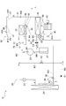
- FIG. 1 is a block diagram illustrating a schematic configuration of the vehicle air conditioner according to the first embodiment.
- FIG. 2 is a block diagram illustrating an electrical configuration of the vehicle air conditioner according to the first embodiment.
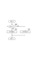
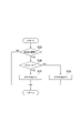
- FIG. 3 is a flowchart illustrating a procedure of processes executed by the vehicle air conditioner according to the first embodiment.
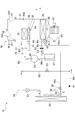
- FIG. 4 is a block diagram illustrating an operation example in the first heating mode in the vehicle air conditioner of the first embodiment.
- FIG. 5 is a block diagram illustrating an operation example in the series dehumidifying heating mode in the vehicle air conditioner according to the first embodiment.
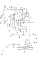
- FIG. 6 is a block diagram illustrating an operation example in the parallel dehumidifying heating mode in the vehicle air conditioner according to the first embodiment.
- FIG. 1 is a block diagram illustrating a schematic configuration of the vehicle air conditioner according to the first embodiment.
- FIG. 2 is a block diagram illustrating an electrical configuration of the vehicle air conditioner according to the first embodiment.
- FIG. 3 is a flowchart illustrating a procedure of processes
- FIG. 7 is a flowchart showing a procedure of a flag F setting process executed by the vehicle air conditioner according to the second embodiment.
- FIG. 8 is a flowchart illustrating a procedure of processes executed by the vehicle air conditioner according to the second embodiment.
- FIG. 9 is a flowchart showing the procedure of the flag F setting process executed by the vehicle air conditioner according to the second embodiment.
- FIG. 10 is a flowchart showing the procedure of the flag F setting process executed by the vehicle air conditioner according to the third embodiment.
- the vehicle air conditioner 10 of the present embodiment shown in FIG. 1 can be mounted on a hybrid vehicle that obtains power for traveling of the vehicle by an engine and an electric motor, for example.
- the air conditioner 10 operates in any one of an operation mode of a cooling mode for cooling the passenger compartment, a heating mode for heating the passenger compartment, and a dehumidifying heating mode for heating while dehumidifying the passenger compartment.
- the air conditioner 10 includes a heat pump cycle device 20, a hot water heater 30, and an air conditioning unit 40.
- the heat pump cycle device 20 is a device that cools or heats air-conditioning air for air-conditioning the vehicle interior.
- the hot water heating device 30 is a device that heats air for air conditioning using heat of cooling water for cooling the engine 31.
- the air conditioning unit 40 is a device that blows out air-conditioning air whose temperature has been adjusted by the heat pump cycle device 20 and the hot water heating device 30 into the vehicle interior.
- the heat pump cycle device 20 includes a compressor 21, a first indoor heat exchanger 22, a first expansion valve 23, an outdoor heat exchanger 24, a second expansion valve 25, a second indoor heat exchanger 26, And an accumulator 27.
- the compressor 21 is an electric compressor that operates based on, for example, electric power supplied from a battery mounted on a vehicle.
- the compressor 21 sucks the refrigerant and compresses it adiabatically to produce a heated refrigerant gas, thereby discharging a high-temperature and high-pressure gas-phase refrigerant.
- the compressor 21 circulates the refrigerant in the heat pump cycle device 20 by sucking and discharging the refrigerant.
- the refrigerant discharged from the compressor 21 flows into the first indoor heat exchanger 22 through the refrigerant flow path W1.
- the first indoor heat exchanger 22 is provided in the air conditioning duct 41 of the air conditioning unit 40.
- the first indoor heat exchanger 22 performs heat exchange between the refrigerant flowing inside the air-conditioning air and the air-conditioning air flowing in the air-conditioning duct 41, thereby radiating the refrigerant and heating the air-conditioning air. That is, the first indoor heat exchanger 22 functions as a condenser.
- the refrigerant that has passed through the first indoor heat exchanger 22 flows to the outdoor heat exchanger 24 through the refrigerant flow path W2.
- the first expansion valve 23 is provided in the middle of the refrigerant flow path W2.
- the first expansion valve 23 is an electric expansion valve whose opening degree can be changed.
- the opening degree of the first expansion valve 23 is set to a fully opened state when the air conditioner 10 is operating in the cooling mode.
- the opening degree of the first expansion valve 23 is set to a predetermined opening degree that is smaller than the fully opened state when the air conditioner 10 is operating in either the heating mode or the dehumidifying heating mode.
- the first expansion valve 23 expands the refrigerant that has passed through the first indoor heat exchanger 22 to generate a low-temperature and low-pressure gas-liquid mixed refrigerant.
- the outdoor heat exchanger 24 exchanges heat between the refrigerant flowing through the outdoor heat exchanger 24 and the outside air blown by the blower fan 28.
- Outside air is air outside the vehicle.
- the temperature of the outside air is abbreviated as “outside temperature”.
- the outdoor heat exchanger 24 radiates the heat of the refrigerant to the outside air by the heat of the outside air temperature. That is, the outdoor heat exchanger 24 functions as a condenser.
- the outdoor heat exchanger 24 causes the refrigerant to absorb the heat of the outside air when the temperature of the refrigerant flowing through the outdoor heat exchanger 24 is lower than the outside air temperature.
- the outdoor heat exchanger 24 functions as an evaporator.
- the refrigerant that has passed through the outdoor heat exchanger 24 flows through one of the refrigerant flow path W3 and the refrigerant flow path W4.
- the refrigerant flow path W ⁇ b> 3 is a flow path that guides the refrigerant that has passed through the outdoor heat exchanger 24 to the accumulator 27.
- the refrigerant flow path W4 is a flow path that guides the refrigerant that has passed through the outdoor heat exchanger 24 to the second indoor heat exchanger 26.
- a solenoid valve 50 is provided in the refrigerant flow path W3.
- the electromagnetic valve 50 opens and closes the refrigerant flow path W3. Therefore, when the solenoid valve 50 is in the open state, the refrigerant that has passed through the outdoor heat exchanger 24 can flow to the accumulator 27 through the refrigerant flow path W3. In addition, when the electromagnetic valve 50 is in the closed state, the refrigerant that has passed through the outdoor heat exchanger 24 can flow to the second indoor heat exchanger 26 through the refrigerant flow path W4.
- a check valve 51 and a second expansion valve 25 are provided in the refrigerant flow path W4.
- the check valve 51 allows the refrigerant flow from the outdoor heat exchanger 24 to the second indoor heat exchanger 26 and prohibits the refrigerant flow in the reverse direction.
- the second expansion valve 25 is provided immediately before the connection portion with the second indoor heat exchanger 26 in the refrigerant flow path W4.
- the second expansion valve 25 is an electric expansion valve whose opening degree can be changed. The second expansion valve 25 expands the refrigerant that has passed through the outdoor heat exchanger 24 and causes the refrigerant to flow into the second indoor heat exchanger 26.
- the second indoor heat exchanger 26 is provided in the air conditioning duct 41 of the air conditioning unit 40.
- the second indoor heat exchanger 26 causes the refrigerant to evaporate by absorbing heat from the air conditioning air by exchanging heat between the refrigerant flowing inside and the air conditioning air flowing in the air conditioning duct 41. That is, the second indoor heat exchanger 26 functions as an evaporator. Air-conditioning air in the air-conditioning duct 41 is cooled and dehumidified by the latent heat of evaporation generated when the refrigerant evaporates.
- the refrigerant that has passed through the second indoor heat exchanger 26 flows into the accumulator 27 by flowing into the middle portion of the refrigerant flow path W3 through the refrigerant flow path W5.
- a pressure regulating valve 52 is provided in a portion upstream of the connection portion C1 with the refrigerant flow path W3 in the refrigerant flow path W5.
- the pressure regulating valve 52 maintains the refrigerant pressure at the outlet portion of the second indoor heat exchanger 26 at a predetermined pressure.
- the accumulator 27 separates the refrigerant flowing in through the refrigerant flow path W3 into a gas phase refrigerant and a liquid phase refrigerant. When the liquid-phase refrigerant flows into the compressor 21, the components of the compressor 21 may be damaged by liquid compression. In order to avoid this, the accumulator 27 supplies only the gas-phase refrigerant to the compressor 21 through the refrigerant flow path W6.
- the heat pump cycle device 20 is provided with a bypass flow path W7 that connects the refrigerant flow path W2 and the refrigerant flow path W4.
- the bypass flow path W7 connects the upstream portion of the first expansion valve 23 in the coolant flow path W2 and the downstream portion of the check valve 51 in the coolant flow path W4.
- the bypass passage W7 allows the refrigerant that has passed through the first indoor heat exchanger 22 to bypass the outdoor heat exchanger 24 and flow to the second indoor heat exchanger 26.
- the electromagnetic valve 53 is provided in the bypass flow path W7.
- the electromagnetic valve 53 opens and closes the bypass flow path W7. Therefore, when the electromagnetic valve 53 is in the open state, the refrigerant that has passed through the first indoor heat exchanger 22 flows to the outdoor heat exchanger 24 or bypasses the outdoor heat exchanger 24 to generate the second indoor heat. It becomes possible to flow to the exchanger 26. Further, when the electromagnetic valve 53 is in the closed state, the refrigerant that has passed through the first indoor heat exchanger 22 can flow to the outdoor heat exchanger 24.
- the hot water heater 30 includes a heater core 32 disposed in the air conditioning duct 41 of the air conditioning unit 40. Cooling water for cooling the engine 31 flows through the heater core 32.
- the heater core 32 heats the air-conditioning air by exchanging heat between the cooling water flowing through the heater core 32 and the air-conditioning air flowing through the air-conditioning duct 41.
- the air conditioning unit 40 includes an air conditioning duct 41, a blower 42, an inside / outside air switching door 43, an air mix door 44, and air outlet switching doors 45 to 47.
- An air passage 410 is formed in the air conditioning duct 41 to guide air for air conditioning into the passenger compartment. In the air passage 410, air flows in the direction indicated by the arrow A in the drawing. In the portion of the air conditioning duct 41 on the upstream side in the air flow direction A, an outside air inlet 411 and an inside air inlet 412 are formed as portions for taking air into the air passage 410.
- the outside air inlet 411 is a part that takes outside air, which is air outside the vehicle, into the air passage 410.
- the inside air inlet 412 is a portion that takes in the inside air, which is air inside the vehicle, into the air passage 410.
- the blower 42, the second indoor heat exchanger 26, the heater core 32, and the first indoor heat exchanger 22 run from the outside air inlet 411 and the inside air inlet 412 toward the downstream side in the air flow direction A. are arranged in order.
- a defroster air outlet 413, a face air outlet 414, and a foot air outlet 415 are formed in the downstream portion of the air conditioning duct 41 in the air flow direction A.
- the defroster outlet 413 blows out air-conditioning air flowing in the air-conditioning duct 41 toward the windshield of the vehicle.
- the face air outlet 414 blows out air-conditioning air flowing in the air-conditioning duct 41 toward the vicinity of the driver's or passenger's face in the passenger seat.
- the foot outlet 415 blows out air-conditioning air flowing in the air-conditioning duct 41 toward the vicinity of the feet of the driver or the passenger on the passenger seat.
- the blower 42 is arranged on the downstream side in the air flow direction A of the outside air inlet 411 and the inside air inlet 412.
- the blower 42 rotates based on the supply of electric power to generate an air flow in the direction indicated by the arrow A in the air passage 410.
- the flow rate of the air flowing through the air passage 410 in other words, the air volume of the air-conditioning air is adjusted.
- the inside / outside air switching door 43 opens and closes the outside air inlet 411 and the inside air inlet 412.
- the inside air inlet 411 is closed and the inside air inlet 412 is opened.
- the air conditioner 10 is in the inside air circulation mode in which the inside air is taken into the air passage 410 from the inside air suction port 412.
- the inside air inlet 412 is closed and the outside air inlet 411 is opened.
- the air conditioner 10 is in an outside air introduction mode in which outside air is taken into the air passage 410 from the outside air inlet 411.
- the air mix door 44 adjusts the ratio between the air volume of the air-conditioning air flowing into the heater core 32 and the first indoor heat exchanger 22 and the air volume of the air-conditioning air bypassing the heater core 32 and the first indoor heat exchanger 22. Specifically, the position of the air mix door 44 can be adjusted between a maximum cooling position indicated by a solid line in the drawing and a maximum heating position indicated by a broken line in the drawing. When the position of the air mix door 44 is the maximum cooling position, most of the air-conditioning air that has passed through the second indoor heat exchanger 26 bypasses the heater core 32 and the first indoor heat exchanger 22.
- the temperature of the air-conditioning air is the lowest.
- the position of the air mix door 44 is the maximum heating position, since most of the air-conditioning air that has passed through the second indoor heat exchanger 26 passes through the heater core 32 and the first indoor heat exchanger 22, air conditioning. The air temperature rises the most.
- the temperature of the air-conditioning air is adjusted by adjusting the opening degree of the air mix door 44 between the maximum heating position and the maximum cooling position.
- the blower outlet switching doors 45 to 47 switch the opening / closing states of the defroster outlet 413, the face outlet 414, and the foot outlet 415, respectively. When at least one of the outlet switching doors 45 to 47 is opened, air-conditioning air is blown out from the opened outlet to the vehicle interior.
- the air conditioner 10 includes temperature sensors 60 to 65 and pressure sensors 70 and 71.
- the temperature sensor 60 detects the temperature Td of the refrigerant discharged from the compressor 21.
- the temperature sensor 61 detects the temperature Th of the refrigerant that has passed through the first indoor heat exchanger 22.
- the temperature sensor 62 detects the temperature Ts of the refrigerant that has passed through the outdoor heat exchanger 24.
- the temperature sensor 63 detects the temperature Tev of the refrigerant that has passed through the second indoor heat exchanger 26.
- the temperature sensor 64 detects the temperature Tw of the cooling water discharged from the heater core 32.
- the temperature sensor 65 detects an intake temperature Tin that is the temperature of the air-conditioning air sucked into the second indoor heat exchanger 26.
- the pressure sensor 70 detects the pressure Ph of the refrigerant that has passed through the first indoor heat exchanger 22.
- the pressure sensor 71 detects the pressure Ps of the refrigerant that has passed through the outdoor heat exchanger 24.
- the air conditioner 10 includes a temperature sensor 66, an inside air temperature sensor 80, an outside air temperature sensor 81, a solar radiation amount sensor 82, an operation device 83, and an ECU (Electronic Control Unit) 90.
- the ECU 90 corresponds to the control unit.
- the temperature sensor 66 detects the blowing temperature Tav which is the temperature of the air-conditioning air blown from the air-conditioning duct 41 into the vehicle interior.
- the internal air temperature sensor 80 detects an internal air temperature Tr, which is the temperature of the air inside the vehicle.
- the outside air temperature sensor 81 detects an outside air temperature Tam that is the temperature of the air outside the vehicle.
- the solar radiation amount sensor 82 detects the solar radiation amount Tsr in the passenger compartment.
- Each of the sensors 60 to 66, 70, 71, and 80 to 82 outputs a signal corresponding to the detected physical quantity.
- the output signals of the sensors 60 to 66, 70, 71, and 80 to 82 are taken into the ECU 90.
- the operating device 83 is disposed, for example, near the instrument panel of the vehicle.
- the operating device 83 includes a temperature setting switch 830, an inside air switch 831, an outside air switch 832, a blow-out port changeover switch 833, an air control switch 834, and the like.
- the air control switch 834 is abbreviated as “A / C switch 834”.
- the temperature setting switch 830 is operated when setting the air conditioning temperature in the passenger compartment.
- the inside air switch 831 is operated when the air conditioner 10 is set to the inside air circulation mode.
- the outside air switch 832 is operated when the air conditioner 10 is set to the outside air circulation mode.
- the air outlet changeover switch 833 is operated when selecting which of the defroster air outlet 413, the face air outlet 414, and the foot air outlet 415 to blow out air for air conditioning.
- the A / C switch 834 is operated when switching between execution and stop of air conditioning air cooling or dehumidification.
- the operation device 83 outputs signals corresponding to the operation information of these switches 830 to 834.
- the output signal of the operating device 83 is taken into the ECU 90.
- the ECU 90 is configured by a known microcomputer having a CPU, a ROM, a RAM, etc., and peripheral circuits thereof. Based on the output signals of the sensors 60 to 66, 70, 71, 80 to 82, and the operating device 83, the ECU 90 performs the compressor 21, the first expansion valve 23, the second expansion valve 25, and the electromagnetic valves 50 and 53. The fan 42 and various doors 43 to 47 are controlled.
- the ECU 90 repeatedly executes the process shown in FIG. 3 at a predetermined cycle. As shown in FIG. 3, the ECU 90 first determines whether or not the target outlet temperature TAO is higher than the intake temperature Tin as a process of step S10.
- the target blowing temperature TAO is the target temperature of the air-conditioning air blown into the vehicle interior. Specifically, the ECU 90 calculates the target blowout temperature TAO based on a predetermined calculation formula from the vehicle interior set temperature set by the temperature setting switch 830, the inside air temperature Tr, the outside air temperature Tam, and the solar radiation amount Tsr.
- step S10 determines whether or not the target outlet temperature TAO is equal to or lower than the intake temperature Tin. If the ECU 90 makes a negative determination in step S10, that is, if the target outlet temperature TAO is equal to or lower than the intake temperature Tin, whether or not the A / C switch 834 is in an on state is determined as step S20. Judging. If the ECU 90 makes a positive determination in step S20, that is, if the A / C switch 834 is on, the ECU 90 operates the air conditioner 10 in the cooling mode as the process in step S21.
- the cooling mode is an operation mode in which the vehicle interior is cooled by the heat pump cycle device 20.
- the ECU90 sets the refrigerant circuit of the heat pump cycle apparatus 20 to the cooling circuit as shown by the arrow in FIG. 1 when the operation mode of the air conditioner 10 is set to the cooling mode. Specifically, the ECU 90 fully opens the first expansion valve 23 and sets the second expansion valve 25 to a predetermined opening. Further, the ECU 90 closes the electromagnetic valves 50 and 53. As a result, the refrigerant flows through the heat pump cycle device 20 as indicated by arrows in FIG. That is, the refrigerant discharged from the compressor 21 includes the first indoor heat exchanger 22, the first expansion valve 23, the outdoor heat exchanger 24, the second expansion valve 25, the second indoor heat exchanger 26, and the pressure adjustment valve 52. Then, it flows in the order of the accumulator 27 and is sucked into the compressor 21 again.
- the ECU 90 sets the position of the air mix door 44 to the maximum cooling position indicated by a solid line in FIG. Further, the ECU 90 estimates the temperature of the air-conditioning air that has passed through the second indoor heat exchanger 26 based on the refrigerant temperature Tev detected by the temperature sensor 63, and the estimated temperature of the air-conditioning air is the target. The rotational speed of the compressor 21 is controlled so as to approach the blowing temperature TAO. Further, the ECU 90 controls the opening degree of the second expansion valve 25 so that the degree of supercooling of the refrigerant flowing into the second expansion valve 25 approaches the target degree of supercooling. The target degree of subcooling is set in advance so that, for example, the COP of the second expansion valve 25 approaches the maximum value.
- the air for air conditioning does not flow to the first indoor heat exchanger 22, so the high-temperature and high-pressure refrigerant discharged from the compressor 21 is contained in the air conditioning duct 41 in the first indoor heat exchanger 22. It flows to the refrigerant flow path W2 without exchanging heat with the air for air conditioning. Further, since the first expansion valve 23 is fully opened, the refrigerant flowing through the refrigerant flow path W2 flows into the outdoor heat exchanger 24 as it is, and radiates heat by exchanging heat with the outside air in the outdoor heat exchanger 24. That is, the outdoor heat exchanger 24 functions as a condenser.
- the refrigerant that has passed through the outdoor heat exchanger 24 is depressurized until it becomes a low-pressure refrigerant in the second expansion valve 25, and then absorbs heat from the air-conditioning air in the air-conditioning duct 41 and evaporates in the second indoor heat exchanger 26. . Thereby, the air for an air conditioning in an air conditioning duct is cooled.
- the outdoor heat exchanger 24 functions as a condenser
- the second indoor heat exchanger 26 functions as an evaporator, whereby the air-conditioning air in the air-conditioning duct 41 is cooled.
- the air-conditioning air cooled in the second indoor heat exchanger 26 flows to the outlets 413 to 415 without flowing through the heater core 32 and the first indoor heat exchanger 22.
- the cooled air-conditioning air is blown into the vehicle interior through the air outlets 413 to 415, thereby cooling the vehicle interior.
- step S20 if the ECU 90 makes a negative determination in step S20, that is, if the A / C switch 834 is in an off state, the air conditioner 10 operates in the blower mode as a process in step S22.
- the ECU 90 stops the heat pump cycle device 20 when the operation mode of the air conditioner 10 is set to the air blowing mode. Further, the ECU 90 sets the position of the air mix door 44 to the maximum cooling position. Thereby, the air sucked into the air conditioning duct 41 from the outside air inlet 411 or the inside air inlet 412 by the blower 42 is directly blown out into the vehicle interior.
- step S10 If the ECU 90 makes an affirmative determination in step S10, that is, if the target outlet temperature TAO is higher than the intake temperature Tin, whether or not the A / C switch 834 is in an on state is determined as a process in step S11. Judging. If the ECU 90 makes a negative determination in the process of step S11, that is, if the A / C switch 834 is in an off state, the ECU 90 operates the air conditioner 10 in the first heating mode as a process of step S19.
- the first heating mode is an operation mode in which the vehicle interior is heated by the heat pump cycle device 20 and the hot water heating device 30.
- ECU90 sets the refrigerant circuit of the heat pump cycle apparatus 20 to a heating circuit as shown by the arrow in FIG. 4 when the operation mode of the air conditioner 10 is set to the first heating mode. Specifically, the ECU 90 sets the first expansion valve 23 to a predetermined opening and closes the second expansion valve 25. In addition, the ECU 90 opens the electromagnetic valve 50 and closes the electromagnetic valve 53. As a result, the refrigerant flows through the heat pump cycle device 20 as indicated by arrows in FIG. That is, the refrigerant discharged from the compressor 21 flows in the order of the first indoor heat exchanger 22, the first expansion valve 23, the outdoor heat exchanger 24, and the accumulator 27 and is sucked into the compressor 21 again.
- the ECU 90 sets the position of the air mix door 44 to the maximum heating position indicated by a solid line in FIG. Further, the ECU 90 controls the rotation speed of the compressor 21 so that the blowing temperature Tav detected by the temperature sensor 66 becomes the target blowing temperature TAO. Further, the ECU 90 controls the opening degree of the first expansion valve 23 so that the degree of supercooling of the refrigerant flowing into the first expansion valve 23 approaches the target degree of supercooling. For example, the target supercooling degree is set in advance so that the COP of the first expansion valve 23 approaches the maximum value.
- the high-temperature and high-pressure refrigerant discharged from the compressor 21 dissipates heat to the air-conditioning air in the air-conditioning duct 41 in the first indoor heat exchanger 22. That is, the first indoor heat exchanger 22 functions as a condenser. Thereby, the air for air conditioning in the air conditioning duct 41 is heated.
- the refrigerant that has passed through the first indoor heat exchanger 22 is depressurized until it becomes a low-pressure refrigerant in the first expansion valve 23, and then absorbs heat by exchanging heat with the outside air in the outdoor heat exchanger 24. That is, the outdoor heat exchanger 24 functions as an evaporator.
- the first indoor heat exchanger 22 functions as a condenser
- the outdoor heat exchanger 24 functions as an evaporator. Heated by at least one of the heat exchanger 22 and the heater core 32. Air-conditioning air heated by at least one of the first indoor heat exchanger 22 and the heater core 32 is blown into the vehicle interior through the respective outlets 413 to 415, whereby the vehicle interior is heated.
- the passing air temperature Tc is changed to the target outlet temperature. It is determined whether or not it is higher than TAO.
- the passing air temperature Tc is the temperature of the air-conditioning air that has passed through the heater core 32.
- the ECU 90 can estimate the passing air temperature Tc based on the cooling water temperature Tw detected by the temperature sensor 64, for example. Therefore, in the present embodiment, the temperature sensor 64 and the ECU 90 correspond to a temperature detection unit that detects the passing air temperature Tc.
- step S12 determines whether or not the passing air temperature Tc is equal to or lower than the target blowing temperature TAO. It is determined that it is difficult to raise. In this case, the ECU 90 determines whether or not the outside air temperature Tam is higher than the first temperature threshold Tth1 as the process of step S16.
- the first temperature threshold value Tth1 is obtained in advance by experiments or the like so that it can be determined whether or not the outside air temperature Tam is a temperature at which the air-conditioning air can be dehumidified by the heat pump cycle device 20.
- the first temperature threshold value Tth1 is set to 0 ° C., for example.
- the ECU 90 makes a negative determination in step S16, that is, when the outside air temperature Tam is equal to or lower than the first temperature threshold Tth1, the ECU 90 determines that the air for air conditioning cannot be dehumidified by the heat pump cycle device 20. In this case, the ECU 90 causes the air conditioner 10 to operate in the first heating mode as in step S19 as the process in step S18.
- the first dehumidifying and heating mode is an operation mode in which heating is performed while dehumidifying the vehicle interior.
- the first dehumidifying and heating mode includes a series dehumidifying and heating mode that is executed during normal times and a parallel dehumidifying and heating mode that is executed when the outside air temperature Tam is low.
- ECU90 sets the refrigerant circuit of the heat pump cycle apparatus 20 to a serial dehumidification heating circuit as shown by an arrow in FIG. 5 when the operation mode of the air conditioner 10 is set to the serial dehumidification heating mode. Specifically, the ECU 90 sets the first expansion valve 23 and the second expansion valve 25 to predetermined opening degrees. Further, the ECU 90 closes the electromagnetic valves 50 and 53. As a result, the refrigerant flows through the heat pump cycle device 20 as indicated by arrows in FIG. That is, in the series dehumidifying heating circuit, the outdoor heat exchanger 24 and the second indoor heat exchanger 26 are connected in series with respect to the refrigerant flow.
- the ECU 90 sets the position of the air mix door 44 to the maximum heating position shown in the drawing. Furthermore, ECU90 controls the opening degree of the 1st expansion valve 23 and the 2nd expansion valve 25 according to the target blowing temperature TAO. Specifically, the ECU 90 changes the opening degree of the first expansion valve 23 in the valve closing direction and the opening degree of the second expansion valve 25 in the valve opening direction as the target blowing temperature TAO increases. . As a result, the flow passage cross-sectional area of the refrigerant flow passage W2 decreases and the flow passage cross-sectional area of the second expansion valve 25 increases as the target blowing temperature TAO increases.
- the high-temperature and high-pressure refrigerant discharged from the compressor 21 dissipates heat to the air-conditioning air in the air-conditioning duct 41 in the first indoor heat exchanger 22. That is, the first indoor heat exchanger 22 functions as a condenser. Thereby, the air for air conditioning in the air conditioning duct 41 is heated.
- the refrigerant that has passed through the first indoor heat exchanger 22 passes through the first expansion valve 23 and flows to the outdoor heat exchanger 24.
- the outdoor heat exchanger 24 functions as a condenser or an evaporator according to the opening degree of the first expansion valve 23 at this time.
- the serial dehumidifying heating mode for example, the following first mode and second mode exist according to the respective opening degrees of the first expansion valve 23 and the second expansion valve 25.
- (A) 1st mode 1st mode is performed when the target blowing temperature TAO is below the predetermined reference temperature.
- the opening degree of the first expansion valve 23 is set to a predetermined opening degree close to the fully opened state.
- the second expansion valve 25 is set to the throttle state.
- the refrigerant that has passed through the first indoor heat exchanger 22 is depressurized until it becomes intermediate pressure refrigerant in the first expansion valve 23, and then flows to the outdoor heat exchanger 24.
- the refrigerant flowing into the outdoor heat exchanger 24 exchanges heat with the outside air in the outdoor heat exchanger 24 to radiate heat. That is, the outdoor heat exchanger 24 functions as a condenser.
- the refrigerant that has passed through the outdoor heat exchanger 24 is depressurized until it becomes a low-pressure refrigerant in the second expansion valve 25, and then absorbs heat from the air-conditioning air in the air-conditioning duct 41 and evaporates in the second indoor heat exchanger 26. .
- the air for air conditioning in an air conditioning duct is cooled and dehumidified.
- the air-conditioning air cooled and dehumidified in the second indoor heat exchanger 26 can be heated in the first indoor heat exchanger 22 and the heater core 32 and blown out into the vehicle interior.
- the vehicle interior can be heated while dehumidifying.
- Second mode The second mode is executed when the target blowing temperature TAO is higher than a predetermined reference temperature.
- the opening degree of the first expansion valve 23 is set to a predetermined opening degree in the valve closing direction than in the first mode.
- the opening degree of the second expansion valve 25 is set to an opening degree in the valve opening direction as compared with the first mode.
- the refrigerant that has passed through the first indoor heat exchanger 22 is depressurized in the first expansion valve 23 until it becomes an intermediate pressure refrigerant having a temperature lower than the outside air temperature Tam, and then the outdoor heat exchange.
- the refrigerant flowing into the outdoor heat exchanger 24 exchanges heat with the outside air in the outdoor heat exchanger 24 and absorbs heat. That is, the outdoor heat exchanger 24 functions as an evaporator.
- the refrigerant that has passed through the outdoor heat exchanger 24 is depressurized until it becomes a low-pressure refrigerant in the second expansion valve 25, and then absorbs heat from the air-conditioning air in the air-conditioning duct 41 and evaporates in the second indoor heat exchanger 26. . Thereby, the air for air conditioning in an air conditioning duct is cooled and dehumidified.
- the air-conditioning air cooled and dehumidified in the second indoor heat exchanger 26 can be heated in the first indoor heat exchanger 22 and the heater core 32 and blown out into the vehicle interior.
- the vehicle interior can be heated while dehumidifying.
- the outdoor heat exchanger 24 functions as an evaporator, in other words, as a heat absorber, so that the amount of heat released from the refrigerant in the first indoor heat exchanger 22 can be increased compared to the second mode. it can.
- the temperature of the air-conditioning air can be increased more than in the second mode.
- ECU90 sets the refrigerant circuit of the heat pump cycle apparatus 20 to a parallel dehumidification heating circuit as shown by an arrow in FIG. 6 when the operation mode of the air conditioner 10 is set to the parallel dehumidification heating mode. Specifically, the ECU 90 sets the first expansion valve 23 and the second expansion valve 25 to predetermined opening degrees. In addition, the ECU 90 closes the electromagnetic valve 50 and opens the electromagnetic valve 53. As a result, the refrigerant flows through the heat pump cycle device 20 as shown by the solid line in FIG. That is, in the parallel dehumidifying and heating circuit, the outdoor heat exchanger 24 and the second indoor heat exchanger 26 are connected in parallel to the refrigerant flow.
- the ECU 90 sets the position of the air mix door 44 to the maximum heating position shown in the drawing. Further, the ECU 90 sets the opening degree of the first expansion valve 23 and the second expansion valve 25 to a predetermined opening degree.
- the high-temperature and high-pressure refrigerant discharged from the compressor 21 dissipates heat to the air-conditioning air in the air-conditioning duct 41 in the first indoor heat exchanger 22. That is, the first indoor heat exchanger 22 functions as a condenser. Thereby, the air for air conditioning in the air conditioning duct 41 is heated.
- the refrigerant that has passed through the first indoor heat exchanger 22 flows to the first expansion valve 23, or flows to the second expansion valve 25 through the bypass flow path W7.
- the refrigerant that has flowed into the first expansion valve 23 is depressurized until it becomes a low-pressure refrigerant, and then flows to the outdoor heat exchanger 24.
- the outdoor heat exchanger 24 exchanges heat with the outside air and absorbs heat from the outside air.
- the refrigerant flowing into the second expansion valve 25 is depressurized until it becomes a low-pressure refrigerant. Then, the low-pressure refrigerant decompressed in the second expansion valve 25 absorbs heat from the air-conditioning air in the air-conditioning duct 41 and evaporates in the second indoor heat exchanger 26. Thereby, the air for air conditioning in an air conditioning duct is cooled and dehumidified.
- the outdoor heat exchanger 24 and the second indoor heat exchanger 26 are connected in parallel to the refrigerant flow.
- the flow rate of the refrigerant flowing into the refrigerant 26 can be reduced. Therefore, since the heat absorption amount of the refrigerant in the second indoor heat exchanger 26 can be reduced, the temperature of the air-conditioning air in the first indoor heat exchanger 22 can be adjusted in a higher temperature range than in the series dehumidifying heating mode. .
- step S12 when the ECU 90 makes an affirmative determination in step S12, that is, when the passing air temperature Tc is higher than the target blowing temperature TAO, the temperature of the air-conditioning air is increased by the heat of the heater core 32. It is determined that it is possible to raise. In this case, the ECU 90 determines whether or not the outside air temperature Tam is higher than the second temperature threshold Tth2 as a process of step S13.
- the second temperature threshold Tth2 is a value smaller than the first temperature threshold Tth1.
- the second temperature threshold value Tth2 is set as follows, for example.
- the temperature of the refrigerant decreases, so that it is difficult to make the second indoor heat exchanger 26 function as an evaporator. Therefore, there is a lower limit for the outside air temperature Tam that can be dehumidified by the second indoor heat exchanger 26 of the heat pump cycle device 20.
- the temperature of the refrigerant decreases as the outside air temperature Tam decreases, the liquid-phase refrigerant easily flows into the compressor 21, so that the operation of the compressor 21 is maintained while avoiding damage due to liquid compression. There is also a lower limit for the possible outside air temperature Tam.
- the lower limit value of the outside air temperature Tam that can be dehumidified by the second indoor heat exchanger 26 of the heat pump cycle device 20 and the lower limit value of the outside air temperature Tam that can maintain the operation of the compressor 21 are obtained by experiments or the like.
- the smaller one of the lower limit values is set as the second temperature threshold value Tth2.
- the second dehumidifying and heating mode is an operation mode in which the vehicle interior is heated by the hot water heater 30 while the vehicle interior is dehumidified by operating the heat pump cycle device 20 in a cooling circuit.
- the ECU90 sets the refrigerant circuit of the heat pump cycle apparatus 20 to a refrigerant circuit as shown by the arrow in FIG. 1 when the operation mode of the air conditioner 10 is set to the second dehumidifying and heating mode. Specifically, the ECU 90 fully opens the first expansion valve 23 and sets the second expansion valve 25 to a predetermined opening. Further, the ECU 90 closes the electromagnetic valves 50 and 53. As a result, the refrigerant flows through the heat pump cycle device 20 as indicated by arrows in FIG. That is, the refrigerant discharged from the compressor 21 includes the first indoor heat exchanger 22, the first expansion valve 23, the outdoor heat exchanger 24, the second expansion valve 25, the second indoor heat exchanger 26, and the pressure adjustment valve 52. Then, it flows in the order of the accumulator 27 and is sucked into the compressor 21 again.
- ECU90 sets the position of the air mix door 44 to the position of a temperature control area, when the operation mode of the air conditioner 10 is set to 2nd dehumidification heating mode.
- the position of the temperature control region indicates an arbitrary position between the maximum heating position and the maximum cooling position.
- the air for air conditioning in the air conditioning duct 41 is dehumidified in the second indoor heat exchanger 26 and heated in the first indoor heat exchanger 22 and the heater core 32.
- the ECU 90 when the ECU 90 makes a negative determination in the process of step S13, that is, when the outside air temperature Tam is equal to or lower than the second temperature threshold value Tth2, the ECU 90 performs the air conditioner 10 as a process of step S15. Operate in second heating mode.
- the ECU 90 stops the heat pump cycle device 20 when the operation mode of the air conditioner 10 is set to the second heating mode. Further, the ECU 90 sets the position of the air mix door 44 to the position of the temperature adjustment region.
- the air-conditioning air flowing in the air-conditioning duct 41 is heated when passing through the heater core 32, and the heated air-conditioning air is blown into the vehicle interior, so that the vehicle interior is heated.
- the processing of steps S16 to S18 executed when the ECU 90 makes a negative determination in the processing of step S12 corresponds to the first processing. Further, the processing of steps S13 to S15 executed when the ECU 90 makes an affirmative determination in the processing of step S12 corresponds to the second processing.
- the ECU 90 of the present embodiment uses the cooling circuit, the heating circuit, and the dehumidifying heating circuit for the refrigerant circuit of the heat pump cycle device 20 based on the passing air temperature Tc that is the temperature of the air conditioning air that has passed through the heater core 32. Selectively switch to either. Accordingly, when the passing air temperature Tc is equal to or lower than the target blowing temperature TAO, that is, when it is difficult to increase the temperature of the air-conditioning air by the heater core 32, the heat pump cycle device 20 is operated by the dehumidifying heating circuit. This makes it possible to dehumidify and heat the air for air conditioning.
- At least the air for air conditioning can be heated by operating the heat pump cycle device 20 in the heating circuit.
- the heat pump cycle device 20 is operated in the cooling circuit. This makes it possible to achieve both dehumidification and heating of the air-conditioning air. At that time, by operating the heat pump cycle device 20 in the cooling circuit, as a secondary effect, dehumidification of the air for air conditioning is performed even in the region of the second temperature threshold Tth2 where the outside air temperature Tam is lower than the first temperature threshold Tth1. It becomes possible. As a result, it is possible to widen the area of the outside air temperature Tam that can be dehumidified.
- the vehicle air conditioner 10 of 2nd Embodiment can set the driving mode to HV mode and EV mode by a driver
- the HV mode is a mode in which the vehicle travels mainly using the power of the engine 31.
- the EV mode is a mode in which the vehicle travels mainly using the power of the electric motor.
- the passing air temperature Tc that is the temperature of the air-conditioning air that has passed through the heater core 32 is higher than the target blowing temperature TAO.
- the ECU 90 may make a positive determination in the process of step S12 in FIG. Therefore, the air conditioner 10 may operate in the second dehumidifying and heating mode.
- the ECU 90 may make a negative determination in the process of step S12 and execute the process of step S18, that is, the air conditioner 10. May be operated in the first heating mode.
- the air conditioner 10 operates in the first heating mode
- the heat pump cycle device 20 operates in the heating circuit shown in FIG. Therefore, since the second indoor heat exchanger 26 does not function as an evaporator, water held in the second indoor heat exchanger 26 may evaporate and be mixed into the air-conditioning air. This causes a strange odor in the air for air conditioning and causes the window glass in the passenger compartment to be fogged.
- the ECU 90 of the present embodiment executes the processing shown in FIGS.
- the ECU 90 determines whether or not the travel mode of the vehicle is the HV mode as a process of step S ⁇ b> 30. If the determination in step S30 is affirmative, that is, if the vehicle travel mode is the HV mode, the ECU 90 sets the flag F to the on state as the process in step S31. Further, when a negative determination is made in the process of step S30, that is, when the traveling mode of the vehicle is the EV mode, the flag F is set to an off state as the process of step S32. After executing the process of step S31 or S32, the ECU 90 once ends a series of processes. The ECU 90 repeatedly executes the process shown in FIG. 7 at a predetermined cycle.
- step S11 when the ECU 90 makes an affirmative determination in the process of step S11, that is, when the A / C switch 834 is on, the flag F is turned on as a process of step S23. It is determined whether or not it is in a state. If the ECU 90 makes an affirmative determination in step S23, that is, if the flag F is on, the ECU 90 includes the first process of steps S16 to S18, including the process of step S12, and steps S13 to S15. The second process is permitted. On the other hand, if the ECU 90 makes a negative determination in the process of step S23, that is, if the flag F is in an off state, the ECU 90 permits only the first process of steps S16 to S18.
- the first process shown in steps S16 to S18 is immediately executed. Therefore, for example, when the outside air temperature Tam is a value in the range from the first temperature threshold value Tth1 to the second temperature threshold value Tth2, the heat pump cycle device 20 operates in the cooling circuit when the vehicle travel mode is the HV mode. Even when the vehicle is running, the heat pump cycle device 20 immediately operates in the heating circuit when the vehicle travel mode is switched to the EV mode. As a result, it is possible to avoid a situation in which water is retained in the second indoor heat exchanger 26 by continuing to operate the heat pump cycle device 20 in the cooling circuit. Can be suppressed.
- the ECU 90 may determine whether the travel mode of the vehicle is the HV mode or the EV mode when the air conditioner 10 is activated, and may hold the determination result until the vehicle stops. Specifically, as shown in FIG. 9, the ECU 90 determines whether or not it is the first time that the air conditioner 10 is started after the engine 31 is started, as the process of step S ⁇ b> 33. If the ECU 90 makes an affirmative determination in step S33, it executes steps S30 to S32.
- the defroster outlet 413 When the defroster outlet 413 is selected as the air-conditioning air outlet, it is considered that the vehicle occupant wants to prioritize dehumidification in the passenger compartment. In such a situation, if the ECU 90 is executing the processing shown in FIGS. 7 and 8, the air conditioner 10 is immediately switched to the heating mode when the vehicle travel mode is switched to the EV mode. There is a risk that the passenger compartment cannot be dehumidified, and as a result, the convenience of the passengers may deteriorate.
- the ECU 90 of the present embodiment executes the process of step S31 or step S32, and then selects the defroster outlet 413 as the air outlet for air conditioning as the process of step S30. Determine whether or not. If the ECU 90 makes a positive determination in step S90, that is, if the defroster outlet 413 is selected as the air-conditioning air outlet, the ECU 90 sets the flag F to the on state.
- the defroster outlet 413 when the defroster outlet 413 is selected as the air outlet for air conditioning, the first process of steps S16 to S18, including the process of step S12 shown in FIG.
- the second process of steps S13 to S15 is permitted. That is, the restriction on processing based on the travel mode is released.
- the process of step S14 or the process of step S17 can be performed and the air for air conditioning can be dehumidified more reliably, the convenience of the passenger can be improved.
- the means and / or functions provided by the ECU 90 can be provided by software stored in a substantial storage device and a computer that executes the software, only software, only hardware, or a combination thereof.
- the ECU 90 when the ECU 90 is provided by an electronic circuit that is hardware, it can be provided by a digital circuit including a large number of logic circuits or an analog circuit.
Landscapes
- Engineering & Computer Science (AREA)
- Mechanical Engineering (AREA)
- Physics & Mathematics (AREA)
- Thermal Sciences (AREA)
- General Engineering & Computer Science (AREA)
- Air-Conditioning For Vehicles (AREA)
Abstract
A vehicular air conditioning device (10) is provided with an air conditioning duct (41), a heater core (32), a heat pump cycle device (20), a temperature detection unit (64, 90), and a control unit (90). The heat pump cycle device includes a first indoor heat exchanger (22), disposed downstream of the heater core in the flow direction of air-conditioning air, a second indoor heat exchanger (26) disposed upstream of the heater core in the flow direction of the air-conditioning air, and an outdoor heat exchanger (24). The temperature detection unit detects the passing-air temperature, which is the temperature of the air-conditioning air that has passed through the heater core. The control unit selectively switches a refrigerant circuit of the heat pump cycle device to a cooling circuit, a heating circuit, or a dehumidification/heating circuit on the basis of the passing-air temperature.
Description
本出願は、2017年5月30日に出願された日本国特許出願2017-106942号に基づくものであって、その優先権の利益を主張するものであり、その特許出願の全ての内容が、参照により本明細書に組み込まれる。
This application is based on Japanese Patent Application No. 2017-106942 filed on May 30, 2017, and claims the benefit of its priority. Which is incorporated herein by reference.
本開示は、車両用空調装置に関する。
The present disclosure relates to a vehicle air conditioner.
従来、特許文献1に記載の車両用空調装置がある。特許文献1に記載の空調装置は、空調ダクト内に配置される凝縮器及び蒸発器と、空調ダクトの外部に配置される室外熱交換器とを備えている。凝縮器、蒸発器、及び室外熱交換器は、蒸気圧縮式の冷凍サイクル装置の冷媒循環回路中に設けられている。この空調装置は、冷媒循環回路中に設けられた弁を切り替えて冷媒の循環経路を切り替えることにより、運転モードを除湿モードと冷房又は暖房モードとの間で切り替えることが可能となっている。特許文献1に記載の空調装置は、外気温及び目標吹出温度の少なくとも一方を含むデータに基づいて運転モードを除湿モードと冷房又は暖房モードとの間で切り替えるECUを備えている。
Conventionally, there is a vehicle air conditioner described in Patent Document 1. The air conditioner described in Patent Literature 1 includes a condenser and an evaporator disposed in an air conditioning duct, and an outdoor heat exchanger disposed outside the air conditioning duct. The condenser, the evaporator, and the outdoor heat exchanger are provided in the refrigerant circulation circuit of the vapor compression refrigeration cycle apparatus. In this air conditioner, the operation mode can be switched between the dehumidifying mode and the cooling or heating mode by switching a valve provided in the refrigerant circulation circuit to switch the refrigerant circulation path. The air conditioner described in Patent Literature 1 includes an ECU that switches an operation mode between a dehumidifying mode and a cooling or heating mode based on data including at least one of an outside air temperature and a target blowing temperature.
近年の車両用空調装置には、ヒートポンプサイクル装置を利用したものがある。ヒートポンプサイクル装置を利用した車両用空調装置では、エンジン冷却水の温度が低い状況でも、車室内に吹き出される空調用空気を加熱することができるため、例えばエンジン始動時に早期に車室内を暖房することが可能であるという利点がある。
Some recent vehicle air conditioners use heat pump cycle devices. In the vehicle air conditioner using the heat pump cycle device, the air-conditioning air blown into the vehicle interior can be heated even in a situation where the temperature of the engine cooling water is low. There is an advantage that it is possible.
一方、ヒートポンプサイクル装置を利用した車両用空調装置は、例えば空調ダクト内に吸い込まれる外気を加熱及び除湿することにより、車室内の暖房及び除湿を可能としている。このような車両用空調装置には、一般的に、ヒートポンプサイクル装置の構成上、空調用空気の加熱及び除湿を両立させることの可能な外気の温度に下限値が存在する。仮に外気の温度が下限値以下に低下すると、空調用空気の加熱能力及び除湿能力が低下するため、車室内の暖房能力と共に除湿能力も低下する。そのため、車両の防曇性が著しく低下する等の弊害がある。
On the other hand, a vehicle air conditioner using a heat pump cycle device enables heating and dehumidification of a vehicle interior by heating and dehumidifying the outside air sucked into the air conditioning duct, for example. In general, such a vehicle air conditioner has a lower limit for the temperature of the outside air that can achieve both heating and dehumidification of air for air conditioning because of the configuration of the heat pump cycle device. If the temperature of the outside air falls below the lower limit value, the heating capacity and the dehumidifying capacity of the air-conditioning air are lowered, so that the dehumidifying capacity is lowered together with the heating capacity of the passenger compartment. For this reason, there are problems such as a significant decrease in the anti-fogging property of the vehicle.
本開示の目的は、車室内の暖房能力を維持しつつ、除湿可能な外気の温度の領域を広げることのできる車両用空調装置を提供することにある。
An object of the present disclosure is to provide a vehicle air conditioner that can expand the temperature range of the outside air that can be dehumidified while maintaining the heating capability of the vehicle interior.
本開示の一態様による車両用空調装置は、空調ダクトと、ヒータコアと、ヒートポンプサイクル装置と、温度検出部と、制御部と、を備える。空調ダクトには、車室内を空調するための空調用空気が流れる。ヒータコアには、空調ダクト内に配置され、車両のエンジンを冷却するための冷却水が流れる。ヒートポンプサイクル装置は、ヒータコアよりも空調用空気の流れ方向の下流側に配置されて空調用空気と冷媒との間で熱交換を行う第1室内熱交換器、ヒータコアよりも空調用空気の流れ方向の上流側に配置されて空調用空気と冷媒との間で熱交換を行う第2室内熱交換器、並びに車両の外部の空気と冷媒との間で熱交換を行う室外熱交換器を有する。温度検出部は、ヒータコアを通過した空調用空気の温度である通過空気温度を検出する。制御部は、ヒートポンプサイクル装置を制御する。制御部は、第1室内熱交換器、第2室内熱交換器、及び室外熱交換器に冷媒を流しつつ、第2室内熱交換器を蒸発器として動作させ、且つ室外熱交換器を凝縮器として動作させることにより、ヒートポンプサイクル装置を冷房回路で動作させる。制御部は、第1室内熱交換器、及び室外熱交換器に冷媒を流しつつ、第1室内熱交換器を凝縮器として動作させ、且つ室外熱交換器を蒸発器として動作させることにより、ヒートポンプサイクル装置を暖房回路で動作させる。制御部は、第1室内熱交換器、第2室内熱交換器、及び室外熱交換器に冷媒を流しつつ、第2室内熱交換器を蒸発器として動作させ、且つ第1室内熱交換器を凝縮器として動作させることにより、ヒートポンプサイクル装置を除湿暖房回路で動作させる。制御部は、通過空気温度に基づいて、ヒートポンプサイクル装置の冷媒回路を冷房回路、暖房回路、及び除湿暖房回路のいずれかに選択的に切り替える。
The vehicle air conditioner according to an aspect of the present disclosure includes an air conditioning duct, a heater core, a heat pump cycle device, a temperature detection unit, and a control unit. Air-conditioning air for air-conditioning the vehicle interior flows through the air-conditioning duct. Cooling water for cooling the engine of the vehicle flows through the heater core in the air conditioning duct. The heat pump cycle device is disposed downstream of the heater core in the air-conditioning air flow direction, and is a first indoor heat exchanger that performs heat exchange between the air-conditioning air and the refrigerant, and the air-conditioning air flow direction from the heater core A second indoor heat exchanger that is disposed on the upstream side of the vehicle and exchanges heat between the air-conditioning air and the refrigerant, and an outdoor heat exchanger that exchanges heat between the air outside the vehicle and the refrigerant. A temperature detection part detects the passing air temperature which is the temperature of the air-conditioning air which passed the heater core. The control unit controls the heat pump cycle device. The control unit causes the second indoor heat exchanger to operate as an evaporator while flowing the refrigerant through the first indoor heat exchanger, the second indoor heat exchanger, and the outdoor heat exchanger, and the outdoor heat exchanger is a condenser. As a result, the heat pump cycle device is operated in the cooling circuit. The control unit operates the first indoor heat exchanger as a condenser and the outdoor heat exchanger as an evaporator while flowing a refrigerant through the first indoor heat exchanger and the outdoor heat exchanger, and operates the outdoor heat exchanger as an evaporator. The cycle device is operated with a heating circuit. The controller causes the second indoor heat exchanger to operate as an evaporator while flowing the refrigerant through the first indoor heat exchanger, the second indoor heat exchanger, and the outdoor heat exchanger, and the first indoor heat exchanger By operating as a condenser, the heat pump cycle device is operated in a dehumidifying heating circuit. The control unit selectively switches the refrigerant circuit of the heat pump cycle device to any one of a cooling circuit, a heating circuit, and a dehumidifying heating circuit based on the passing air temperature.
この構成によれば、温度検出部により検出される通過空気温度が低い場合には、すなわちヒータコアにより空調用空気の温度を上昇させることが難しい場合には、ヒートポンプサイクル装置を除湿暖房回路で動作させることにより、空調用空気の除湿及び暖房の両立が可能となる。なお、空調用空気の除湿が難しい状況下では、ヒートポンプサイクル装置を暖房回路で動作させることにより、少なくとも空調用空気の加熱が可能となる。
According to this configuration, when the passing air temperature detected by the temperature detection unit is low, that is, when it is difficult to increase the temperature of the air-conditioning air by the heater core, the heat pump cycle device is operated by the dehumidifying heating circuit. This makes it possible to achieve both dehumidification and heating of the air-conditioning air. In a situation where it is difficult to dehumidify the air for air conditioning, the air for air conditioning can be heated at least by operating the heat pump cycle device with a heating circuit.
一方、温度検出部により検出される通過空気温度が高い場合には、すなわちヒータコアにより空調用空気の温度を上昇させることが可能な場合には、ヒートポンプサイクル装置を冷房回路で動作させることにより、空調用空気の除湿及び暖房の両立が可能となる。また、ヒートポンプサイクル装置を冷房回路で動作させることにより、その副次的な効果として、車両の外部の温度がより低い状況でも空調用空気を除湿することが可能となる。結果として、除湿の可能な外気の温度領域を広げることが可能となる。
On the other hand, when the temperature of the passing air detected by the temperature detector is high, that is, when the temperature of the air-conditioning air can be increased by the heater core, the air conditioning is performed by operating the heat pump cycle device in the cooling circuit. Both dehumidification of heating air and heating can be achieved. Further, by operating the heat pump cycle device in the cooling circuit, as a secondary effect, it becomes possible to dehumidify the air-conditioning air even in a situation where the temperature outside the vehicle is lower. As a result, it is possible to expand the temperature range of the outside air that can be dehumidified.
以下、車両用空調装置の実施形態について図面を参照しながら説明する。説明の理解を容易にするため、各図面において同一の構成要素に対しては可能な限り同一の符号を付して、重複する説明は省略する。
<第1実施形態>
はじめに、車両用空調装置の第1実施形態について説明する。図1に示される本実施形態の車両用空調装置10は、例えばエンジン及び電動機により車両の走行用の動力を得るハイブリッド車両に搭載することができる。空調装置10は、車室内を冷房する冷房モード、車室内を暖房する暖房モード、及び車室内を除湿しつつ暖房する除湿暖房モードのいずれかの運転モードで動作する。 Hereinafter, an embodiment of a vehicle air conditioner will be described with reference to the drawings. In order to facilitate the understanding of the description, the same constituent elements in the drawings will be denoted by the same reference numerals as much as possible, and redundant description will be omitted.
<First Embodiment>
First, a first embodiment of a vehicle air conditioner will be described. Thevehicle air conditioner 10 of the present embodiment shown in FIG. 1 can be mounted on a hybrid vehicle that obtains power for traveling of the vehicle by an engine and an electric motor, for example. The air conditioner 10 operates in any one of an operation mode of a cooling mode for cooling the passenger compartment, a heating mode for heating the passenger compartment, and a dehumidifying heating mode for heating while dehumidifying the passenger compartment.
<第1実施形態>
はじめに、車両用空調装置の第1実施形態について説明する。図1に示される本実施形態の車両用空調装置10は、例えばエンジン及び電動機により車両の走行用の動力を得るハイブリッド車両に搭載することができる。空調装置10は、車室内を冷房する冷房モード、車室内を暖房する暖房モード、及び車室内を除湿しつつ暖房する除湿暖房モードのいずれかの運転モードで動作する。 Hereinafter, an embodiment of a vehicle air conditioner will be described with reference to the drawings. In order to facilitate the understanding of the description, the same constituent elements in the drawings will be denoted by the same reference numerals as much as possible, and redundant description will be omitted.
<First Embodiment>
First, a first embodiment of a vehicle air conditioner will be described. The
図1に示されるように、空調装置10は、ヒートポンプサイクル装置20と、温水暖房装置30と、空調ユニット40とを備えている。ヒートポンプサイクル装置20は、車室内を空調するための空調用空気を冷却又は加熱する装置である。温水暖房装置30は、エンジン31を冷却するための冷却水の有する熱を利用して空調用空気を加熱する装置である。空調ユニット40は、ヒートポンプサイクル装置20及び温水暖房装置30により温度の調整された空調用空気を車室内に吹き出す装置である。
As shown in FIG. 1, the air conditioner 10 includes a heat pump cycle device 20, a hot water heater 30, and an air conditioning unit 40. The heat pump cycle device 20 is a device that cools or heats air-conditioning air for air-conditioning the vehicle interior. The hot water heating device 30 is a device that heats air for air conditioning using heat of cooling water for cooling the engine 31. The air conditioning unit 40 is a device that blows out air-conditioning air whose temperature has been adjusted by the heat pump cycle device 20 and the hot water heating device 30 into the vehicle interior.
ヒートポンプサイクル装置20は、圧縮機21と、第1室内熱交換器22と、第1膨張弁23と、室外熱交換器24と、第2膨張弁25と、第2室内熱交換器26と、アキュームレータ27とを備えている。
圧縮機21は、例えば車両に搭載されたバッテリから供給される電力に基づいて作動する電動式の圧縮機である。圧縮機21は、冷媒を吸入するとともに、断熱的に圧縮して加熱状態の冷媒ガスとすることにより、高温及び高圧の気相状の冷媒を吐出する。圧縮機21は、冷媒を吸入及び吐出することにより、ヒートポンプサイクル装置20に冷媒を循環させる。圧縮機21から吐出される冷媒は、冷媒流路W1を通じて第1室内熱交換器22に流入する。 The heatpump cycle device 20 includes a compressor 21, a first indoor heat exchanger 22, a first expansion valve 23, an outdoor heat exchanger 24, a second expansion valve 25, a second indoor heat exchanger 26, And an accumulator 27.
Thecompressor 21 is an electric compressor that operates based on, for example, electric power supplied from a battery mounted on a vehicle. The compressor 21 sucks the refrigerant and compresses it adiabatically to produce a heated refrigerant gas, thereby discharging a high-temperature and high-pressure gas-phase refrigerant. The compressor 21 circulates the refrigerant in the heat pump cycle device 20 by sucking and discharging the refrigerant. The refrigerant discharged from the compressor 21 flows into the first indoor heat exchanger 22 through the refrigerant flow path W1.
圧縮機21は、例えば車両に搭載されたバッテリから供給される電力に基づいて作動する電動式の圧縮機である。圧縮機21は、冷媒を吸入するとともに、断熱的に圧縮して加熱状態の冷媒ガスとすることにより、高温及び高圧の気相状の冷媒を吐出する。圧縮機21は、冷媒を吸入及び吐出することにより、ヒートポンプサイクル装置20に冷媒を循環させる。圧縮機21から吐出される冷媒は、冷媒流路W1を通じて第1室内熱交換器22に流入する。 The heat
The
第1室内熱交換器22は、空調ユニット40の空調ダクト41内に設けられている。第1室内熱交換器22は、その内部を流れる冷媒と、空調ダクト41内を流れる空調用空気とを熱交換させることにより、冷媒を放熱させるとともに、空調用空気を加熱する。すなわち、第1室内熱交換器22は、凝縮器として機能する。第1室内熱交換器22を通過した冷媒は、冷媒流路W2を通じて室外熱交換器24へ流れる。
The first indoor heat exchanger 22 is provided in the air conditioning duct 41 of the air conditioning unit 40. The first indoor heat exchanger 22 performs heat exchange between the refrigerant flowing inside the air-conditioning air and the air-conditioning air flowing in the air-conditioning duct 41, thereby radiating the refrigerant and heating the air-conditioning air. That is, the first indoor heat exchanger 22 functions as a condenser. The refrigerant that has passed through the first indoor heat exchanger 22 flows to the outdoor heat exchanger 24 through the refrigerant flow path W2.
第1膨張弁23は、冷媒流路W2の途中に設けられている。第1膨張弁23は、その開度を変更可能な電動式の膨張弁からなる。第1膨張弁23の開度は、空調装置10が冷房モードで動作している場合には、全開状態に設定される。また、第1膨張弁23の開度は、空調装置10が暖房モード及び除湿暖房モードのいずれかで動作している場合には、全開状態よりも小さい所定の開度に設定される。第1膨張弁23は、所定の開度に設定されている場合、第1室内熱交換器22を通過した冷媒を膨張させることにより、低温及び低圧の気液混合状態の冷媒を生成する。
The first expansion valve 23 is provided in the middle of the refrigerant flow path W2. The first expansion valve 23 is an electric expansion valve whose opening degree can be changed. The opening degree of the first expansion valve 23 is set to a fully opened state when the air conditioner 10 is operating in the cooling mode. Moreover, the opening degree of the first expansion valve 23 is set to a predetermined opening degree that is smaller than the fully opened state when the air conditioner 10 is operating in either the heating mode or the dehumidifying heating mode. When the first expansion valve 23 is set to a predetermined opening, the first expansion valve 23 expands the refrigerant that has passed through the first indoor heat exchanger 22 to generate a low-temperature and low-pressure gas-liquid mixed refrigerant.
室外熱交換器24は、その内部を流れる冷媒と、送風ファン28により送風される外気とを熱交換させる。外気は、車両の外部の空気である。以下では、外気の温度を「外気温」と略記する。室外熱交換器24は、その内部を流れる冷媒の温度が外気温よりも高い場合には、外気温の熱により冷媒の熱を外気に放熱させる。すなわち、室外熱交換器24は、凝縮器として機能する。また、室外熱交換器24は、その内部を流れる冷媒の温度が外気温よりも低い場合には、外気の熱を冷媒に吸収させる。すなわち、室外熱交換器24は、蒸発器として機能する。室外熱交換器24を通過した冷媒は、冷媒流路W3及び冷媒流路W4のいずれか一方を流れる。冷媒流路W3は、室外熱交換器24を通過した冷媒をアキュームレータ27に導く流路である。冷媒流路W4は、室外熱交換器24を通過した冷媒を第2室内熱交換器26に導く流路である。
The outdoor heat exchanger 24 exchanges heat between the refrigerant flowing through the outdoor heat exchanger 24 and the outside air blown by the blower fan 28. Outside air is air outside the vehicle. Hereinafter, the temperature of the outside air is abbreviated as “outside temperature”. When the temperature of the refrigerant flowing through the outdoor heat exchanger 24 is higher than the outside air temperature, the outdoor heat exchanger 24 radiates the heat of the refrigerant to the outside air by the heat of the outside air temperature. That is, the outdoor heat exchanger 24 functions as a condenser. In addition, the outdoor heat exchanger 24 causes the refrigerant to absorb the heat of the outside air when the temperature of the refrigerant flowing through the outdoor heat exchanger 24 is lower than the outside air temperature. That is, the outdoor heat exchanger 24 functions as an evaporator. The refrigerant that has passed through the outdoor heat exchanger 24 flows through one of the refrigerant flow path W3 and the refrigerant flow path W4. The refrigerant flow path W <b> 3 is a flow path that guides the refrigerant that has passed through the outdoor heat exchanger 24 to the accumulator 27. The refrigerant flow path W4 is a flow path that guides the refrigerant that has passed through the outdoor heat exchanger 24 to the second indoor heat exchanger 26.
冷媒流路W3には、電磁弁50が設けられている。電磁弁50は、冷媒流路W3を開閉させる。したがって、電磁弁50が開状態である場合、室外熱交換器24を通過した冷媒は、冷媒流路W3を通じてアキュームレータ27へ流れることが可能となる。また、電磁弁50が閉状態である場合には、室外熱交換器24を通過した冷媒は、冷媒流路W4を通じて第2室内熱交換器26へ流れることが可能となる。
A solenoid valve 50 is provided in the refrigerant flow path W3. The electromagnetic valve 50 opens and closes the refrigerant flow path W3. Therefore, when the solenoid valve 50 is in the open state, the refrigerant that has passed through the outdoor heat exchanger 24 can flow to the accumulator 27 through the refrigerant flow path W3. In addition, when the electromagnetic valve 50 is in the closed state, the refrigerant that has passed through the outdoor heat exchanger 24 can flow to the second indoor heat exchanger 26 through the refrigerant flow path W4.
冷媒流路W4には、逆止弁51と、第2膨張弁25とが設けられている。逆止弁51は、室外熱交換器24から第2室内熱交換器26への冷媒の流れを許容するとともに、その逆方向の冷媒の流れを禁止する。第2膨張弁25は、冷媒流路W4において第2室内熱交換器26との接続部分の直前に設けられている。第2膨張弁25は、その開度を変更可能な電動式の膨張弁からなる。第2膨張弁25は、室外熱交換器24を通過した冷媒を膨張させて第2室内熱交換器26に流入させる。
In the refrigerant flow path W4, a check valve 51 and a second expansion valve 25 are provided. The check valve 51 allows the refrigerant flow from the outdoor heat exchanger 24 to the second indoor heat exchanger 26 and prohibits the refrigerant flow in the reverse direction. The second expansion valve 25 is provided immediately before the connection portion with the second indoor heat exchanger 26 in the refrigerant flow path W4. The second expansion valve 25 is an electric expansion valve whose opening degree can be changed. The second expansion valve 25 expands the refrigerant that has passed through the outdoor heat exchanger 24 and causes the refrigerant to flow into the second indoor heat exchanger 26.
第2室内熱交換器26は、空調ユニット40の空調ダクト41内に設けられている。第2室内熱交換器26は、その内部を流れる冷媒と、空調ダクト41内を流れる空調用空気とを熱交換させることにより、空調用空気の熱を冷媒に吸収させて冷媒を蒸発させる。すなわち、第2室内熱交換器26は、蒸発器として機能する。冷媒が蒸発する際に発生する蒸発潜熱により、空調ダクト41内の空調用空気が冷却されるとともに除湿される。第2室内熱交換器26を通過した冷媒は、冷媒流路W5を通じて冷媒流路W3の途中部分に流入することにより、アキュームレータ27へ流れる。
The second indoor heat exchanger 26 is provided in the air conditioning duct 41 of the air conditioning unit 40. The second indoor heat exchanger 26 causes the refrigerant to evaporate by absorbing heat from the air conditioning air by exchanging heat between the refrigerant flowing inside and the air conditioning air flowing in the air conditioning duct 41. That is, the second indoor heat exchanger 26 functions as an evaporator. Air-conditioning air in the air-conditioning duct 41 is cooled and dehumidified by the latent heat of evaporation generated when the refrigerant evaporates. The refrigerant that has passed through the second indoor heat exchanger 26 flows into the accumulator 27 by flowing into the middle portion of the refrigerant flow path W3 through the refrigerant flow path W5.
冷媒流路W5における冷媒流路W3との接続部分C1よりも上流側の部分には、圧力調整弁52が設けられている。圧力調整弁52は、第2室内熱交換器26の出口部分における冷媒の圧力を所定の圧力に維持する。
アキュームレータ27は、冷媒流路W3を通じて流入する冷媒を気相状の冷媒と液相状の冷媒とに分離する。液相状の冷媒が圧縮機21に流入すると圧縮機21の構成部品が液圧縮により破損する可能性がある。これを回避するため、アキュームレータ27は、気相状の冷媒のみを冷媒流路W6を通じて圧縮機21に供給する。 Apressure regulating valve 52 is provided in a portion upstream of the connection portion C1 with the refrigerant flow path W3 in the refrigerant flow path W5. The pressure regulating valve 52 maintains the refrigerant pressure at the outlet portion of the second indoor heat exchanger 26 at a predetermined pressure.
Theaccumulator 27 separates the refrigerant flowing in through the refrigerant flow path W3 into a gas phase refrigerant and a liquid phase refrigerant. When the liquid-phase refrigerant flows into the compressor 21, the components of the compressor 21 may be damaged by liquid compression. In order to avoid this, the accumulator 27 supplies only the gas-phase refrigerant to the compressor 21 through the refrigerant flow path W6.
アキュームレータ27は、冷媒流路W3を通じて流入する冷媒を気相状の冷媒と液相状の冷媒とに分離する。液相状の冷媒が圧縮機21に流入すると圧縮機21の構成部品が液圧縮により破損する可能性がある。これを回避するため、アキュームレータ27は、気相状の冷媒のみを冷媒流路W6を通じて圧縮機21に供給する。 A
The
ヒートポンプサイクル装置20には、冷媒流路W2と冷媒流路W4とを接続するバイパス流路W7が設けられている。バイパス流路W7は、冷媒流路W2における第1膨張弁23の上流側の部分と、冷媒流路W4における逆止弁51の下流側の部分とを接続している。このバイパス流路W7により、第1室内熱交換器22を通過した冷媒は、室外熱交換器24をバイパスして、第2室内熱交換器26へ流れることが可能となっている。
The heat pump cycle device 20 is provided with a bypass flow path W7 that connects the refrigerant flow path W2 and the refrigerant flow path W4. The bypass flow path W7 connects the upstream portion of the first expansion valve 23 in the coolant flow path W2 and the downstream portion of the check valve 51 in the coolant flow path W4. The bypass passage W7 allows the refrigerant that has passed through the first indoor heat exchanger 22 to bypass the outdoor heat exchanger 24 and flow to the second indoor heat exchanger 26.
バイパス流路W7には、電磁弁53が設けられている。電磁弁53は、バイパス流路W7を開閉させる。したがって、電磁弁53が開状態である場合には、第1室内熱交換器22を通過した冷媒は、室外熱交換器24へ流れるか、あるいは室外熱交換器24をバイパスして第2室内熱交換器26へ流れることが可能となる。また、電磁弁53が閉状態である場合には、第1室内熱交換器22を通過した冷媒は、室外熱交換器24へ流れることが可能となる。
The electromagnetic valve 53 is provided in the bypass flow path W7. The electromagnetic valve 53 opens and closes the bypass flow path W7. Therefore, when the electromagnetic valve 53 is in the open state, the refrigerant that has passed through the first indoor heat exchanger 22 flows to the outdoor heat exchanger 24 or bypasses the outdoor heat exchanger 24 to generate the second indoor heat. It becomes possible to flow to the exchanger 26. Further, when the electromagnetic valve 53 is in the closed state, the refrigerant that has passed through the first indoor heat exchanger 22 can flow to the outdoor heat exchanger 24.
温水暖房装置30は、空調ユニット40の空調ダクト41内に配置されるヒータコア32を備えている。ヒータコア32には、エンジン31を冷却するための冷却水が流れている。ヒータコア32は、その内部を流れる冷却水と、空調ダクト41内を流れる空調用空気とを熱交換させることにより、空調用空気を加熱する。
The hot water heater 30 includes a heater core 32 disposed in the air conditioning duct 41 of the air conditioning unit 40. Cooling water for cooling the engine 31 flows through the heater core 32. The heater core 32 heats the air-conditioning air by exchanging heat between the cooling water flowing through the heater core 32 and the air-conditioning air flowing through the air-conditioning duct 41.
空調ユニット40は、空調ダクト41と、送風機42と、内外気切替ドア43と、エアミックスドア44と、吹出口切替ドア45~47とを備えている。
空調ダクト41の内部には、空調用空気を車室内に導く空気通路410が形成されている。空気通路410内では、図中に矢印Aで示される方向に空気が流れる。空調ダクト41の空気流れ方向Aの上流側の部分には、空気通路410内に空気を取り込む部分として、外気吸込口411と、内気吸込口412とが形成されている。外気吸込口411は、車両の外部の空気である外気を空気通路410内に取り込む部分である。内気吸込口412は、車両の内部の空気である内気を空気通路410内に取り込む部分である。空調ダクト41内には、外気吸込口411及び内気吸込口412から空気流れ方向Aの下流側に向かって、送風機42、第2室内熱交換器26、ヒータコア32、及び第1室内熱交換器22が順に配置されている。 Theair conditioning unit 40 includes an air conditioning duct 41, a blower 42, an inside / outside air switching door 43, an air mix door 44, and air outlet switching doors 45 to 47.
Anair passage 410 is formed in the air conditioning duct 41 to guide air for air conditioning into the passenger compartment. In the air passage 410, air flows in the direction indicated by the arrow A in the drawing. In the portion of the air conditioning duct 41 on the upstream side in the air flow direction A, an outside air inlet 411 and an inside air inlet 412 are formed as portions for taking air into the air passage 410. The outside air inlet 411 is a part that takes outside air, which is air outside the vehicle, into the air passage 410. The inside air inlet 412 is a portion that takes in the inside air, which is air inside the vehicle, into the air passage 410. In the air conditioning duct 41, the blower 42, the second indoor heat exchanger 26, the heater core 32, and the first indoor heat exchanger 22 run from the outside air inlet 411 and the inside air inlet 412 toward the downstream side in the air flow direction A. Are arranged in order.
空調ダクト41の内部には、空調用空気を車室内に導く空気通路410が形成されている。空気通路410内では、図中に矢印Aで示される方向に空気が流れる。空調ダクト41の空気流れ方向Aの上流側の部分には、空気通路410内に空気を取り込む部分として、外気吸込口411と、内気吸込口412とが形成されている。外気吸込口411は、車両の外部の空気である外気を空気通路410内に取り込む部分である。内気吸込口412は、車両の内部の空気である内気を空気通路410内に取り込む部分である。空調ダクト41内には、外気吸込口411及び内気吸込口412から空気流れ方向Aの下流側に向かって、送風機42、第2室内熱交換器26、ヒータコア32、及び第1室内熱交換器22が順に配置されている。 The
An
空調ダクト41の空気流れ方向Aの下流側の部分には、デフロスタ吹出口413と、フェイス吹出口414と、フット吹出口415とが形成されている。デフロスタ吹出口413は、空調ダクト41内を流れる空調用空気を車両のフロントガラスに向かって吹き出す。フェイス吹出口414は、空調ダクト41内を流れる空調用空気を運転者又は助手席の乗員の顔付近に向かって吹き出す。フット吹出口415は、空調ダクト41内を流れる空調用空気を運転者又は助手席の乗員の足下付近に向かって吹き出す。
A defroster air outlet 413, a face air outlet 414, and a foot air outlet 415 are formed in the downstream portion of the air conditioning duct 41 in the air flow direction A. The defroster outlet 413 blows out air-conditioning air flowing in the air-conditioning duct 41 toward the windshield of the vehicle. The face air outlet 414 blows out air-conditioning air flowing in the air-conditioning duct 41 toward the vicinity of the driver's or passenger's face in the passenger seat. The foot outlet 415 blows out air-conditioning air flowing in the air-conditioning duct 41 toward the vicinity of the feet of the driver or the passenger on the passenger seat.
送風機42は、外気吸込口411及び内気吸込口412の空気流れ方向Aの下流側に配置されている。送風機42は、電力の供給に基づき回転することにより空気通路410内に、矢印Aで示される方向の空気流を発生させる。送風機42に供給される電力の調整により、空気通路410内を流れる空気の流量、換言すれば空調用空気の風量が調整される。
The blower 42 is arranged on the downstream side in the air flow direction A of the outside air inlet 411 and the inside air inlet 412. The blower 42 rotates based on the supply of electric power to generate an air flow in the direction indicated by the arrow A in the air passage 410. By adjusting the power supplied to the blower 42, the flow rate of the air flowing through the air passage 410, in other words, the air volume of the air-conditioning air is adjusted.
内外気切替ドア43は、外気吸込口411及び内気吸込口412を開閉させる。内外気切替ドア43が図中に実線で示される内気導入位置に位置している場合、外気吸込口411が閉塞されるとともに、内気吸込口412が開口される。この場合、空調装置10は、内気吸込口412から空気通路410内に内気を取り込む内気循環モードとなる。一方、内外気切替ドア43が図中に破線で示される外気導入位置に位置している場合、内気吸込口412が閉塞されるとともに、外気吸込口411が開口される。この場合、空調装置10は、外気吸込口411から空気通路410内に外気を取り込む外気導入モードとなる。
The inside / outside air switching door 43 opens and closes the outside air inlet 411 and the inside air inlet 412. When the inside / outside air switching door 43 is located at the inside air introduction position indicated by a solid line in the drawing, the outside air inlet 411 is closed and the inside air inlet 412 is opened. In this case, the air conditioner 10 is in the inside air circulation mode in which the inside air is taken into the air passage 410 from the inside air suction port 412. On the other hand, when the inside / outside air switching door 43 is located at an outside air introduction position indicated by a broken line in the drawing, the inside air inlet 412 is closed and the outside air inlet 411 is opened. In this case, the air conditioner 10 is in an outside air introduction mode in which outside air is taken into the air passage 410 from the outside air inlet 411.
エアミックスドア44は、ヒータコア32及び第1室内熱交換器22に流入する空調用空気の風量と、ヒータコア32及び第1室内熱交換器22を迂回する空調用空気の風量との比率を調整する。具体的には、エアミックスドア44の位置は、図中に実線で示される最大冷房位置と、図中に破線で示される最大暖房位置との間で調整することが可能となっている。エアミックスドア44の位置が最大冷房位置である場合、第2室内熱交換器26を通過した空調用空気のほとんどがヒータコア32及び第1室内熱交換器22を迂回する。この場合、第2室内熱交換器26で冷却された空気がそのまま各吹出口413~415へ流れるため、空調用空気の温度が最も低下する。これに対し、エアミックスドア44の位置が最大暖房位置である場合、第2室内熱交換器26を通過した空調用空気のほとんどがヒータコア32及び第1室内熱交換器22を通過するため、空調用空気の温度が最も上昇する。空調装置10では、エアミックスドア44の開度が最大暖房位置と最大冷房位置との間で調整されることで、空調用空気の温度が調整される。
The air mix door 44 adjusts the ratio between the air volume of the air-conditioning air flowing into the heater core 32 and the first indoor heat exchanger 22 and the air volume of the air-conditioning air bypassing the heater core 32 and the first indoor heat exchanger 22. . Specifically, the position of the air mix door 44 can be adjusted between a maximum cooling position indicated by a solid line in the drawing and a maximum heating position indicated by a broken line in the drawing. When the position of the air mix door 44 is the maximum cooling position, most of the air-conditioning air that has passed through the second indoor heat exchanger 26 bypasses the heater core 32 and the first indoor heat exchanger 22. In this case, since the air cooled by the second indoor heat exchanger 26 flows as it is to the air outlets 413 to 415, the temperature of the air-conditioning air is the lowest. On the other hand, when the position of the air mix door 44 is the maximum heating position, since most of the air-conditioning air that has passed through the second indoor heat exchanger 26 passes through the heater core 32 and the first indoor heat exchanger 22, air conditioning. The air temperature rises the most. In the air conditioner 10, the temperature of the air-conditioning air is adjusted by adjusting the opening degree of the air mix door 44 between the maximum heating position and the maximum cooling position.
吹出口切替ドア45~47は、デフロスタ吹出口413、フェイス吹出口414、及びフット吹出口415のそれぞれの開閉状態を切り替える。吹出口切替ドア45~47の少なくとも1つが開状態となることにより、開状態の吹出口から車室内に向けて空調用空気が吹き出される。
The blower outlet switching doors 45 to 47 switch the opening / closing states of the defroster outlet 413, the face outlet 414, and the foot outlet 415, respectively. When at least one of the outlet switching doors 45 to 47 is opened, air-conditioning air is blown out from the opened outlet to the vehicle interior.
次に、空調装置10の電気的な構成について説明する。
図1に示されるように、空調装置10は、温度センサ60~65と、圧力センサ70,71とを備えている。
温度センサ60は、圧縮機21から吐出される冷媒の温度Tdを検出する。温度センサ61は、第1室内熱交換器22を通過した冷媒の温度Thを検出する。温度センサ62は、室外熱交換器24を通過した冷媒の温度Tsを検出する。温度センサ63は、第2室内熱交換器26を通過した冷媒の温度Tevを検出する。温度センサ64は、ヒータコア32から吐出される冷却水の温度Twを検出する。温度センサ65は、第2室内熱交換器26に吸入される空調用空気の温度である吸入温度Tinを検出する。 Next, the electrical configuration of theair conditioner 10 will be described.
As shown in FIG. 1, theair conditioner 10 includes temperature sensors 60 to 65 and pressure sensors 70 and 71.
Thetemperature sensor 60 detects the temperature Td of the refrigerant discharged from the compressor 21. The temperature sensor 61 detects the temperature Th of the refrigerant that has passed through the first indoor heat exchanger 22. The temperature sensor 62 detects the temperature Ts of the refrigerant that has passed through the outdoor heat exchanger 24. The temperature sensor 63 detects the temperature Tev of the refrigerant that has passed through the second indoor heat exchanger 26. The temperature sensor 64 detects the temperature Tw of the cooling water discharged from the heater core 32. The temperature sensor 65 detects an intake temperature Tin that is the temperature of the air-conditioning air sucked into the second indoor heat exchanger 26.
図1に示されるように、空調装置10は、温度センサ60~65と、圧力センサ70,71とを備えている。
温度センサ60は、圧縮機21から吐出される冷媒の温度Tdを検出する。温度センサ61は、第1室内熱交換器22を通過した冷媒の温度Thを検出する。温度センサ62は、室外熱交換器24を通過した冷媒の温度Tsを検出する。温度センサ63は、第2室内熱交換器26を通過した冷媒の温度Tevを検出する。温度センサ64は、ヒータコア32から吐出される冷却水の温度Twを検出する。温度センサ65は、第2室内熱交換器26に吸入される空調用空気の温度である吸入温度Tinを検出する。 Next, the electrical configuration of the
As shown in FIG. 1, the
The
圧力センサ70は、第1室内熱交換器22を通過した冷媒の圧力Phを検出する。圧力センサ71は、室外熱交換器24を通過した冷媒の圧力Psを検出する。
また、図2に示されるように、空調装置10は、温度センサ66と、内気温センサ80と、外気温センサ81と、日射量センサ82と、操作装置83と、ECU(Electronic Control Unit)90とを更に備えている。本実施形態では、ECU90が制御部に相当する。 Thepressure sensor 70 detects the pressure Ph of the refrigerant that has passed through the first indoor heat exchanger 22. The pressure sensor 71 detects the pressure Ps of the refrigerant that has passed through the outdoor heat exchanger 24.
As shown in FIG. 2, theair conditioner 10 includes a temperature sensor 66, an inside air temperature sensor 80, an outside air temperature sensor 81, a solar radiation amount sensor 82, an operation device 83, and an ECU (Electronic Control Unit) 90. Are further provided. In the present embodiment, the ECU 90 corresponds to the control unit.
また、図2に示されるように、空調装置10は、温度センサ66と、内気温センサ80と、外気温センサ81と、日射量センサ82と、操作装置83と、ECU(Electronic Control Unit)90とを更に備えている。本実施形態では、ECU90が制御部に相当する。 The
As shown in FIG. 2, the
温度センサ66は、空調ダクト41から車室内に吹き出される空調用空気の温度である吹出温度Tavを検出する。内気温センサ80は、車両の内部の空気の温度である内気温Trを検出する。外気温センサ81は、車両の外部の空気の温度である外気温Tamを検出する。日射量センサ82は、車室内の日射量Tsrを検出する。
The temperature sensor 66 detects the blowing temperature Tav which is the temperature of the air-conditioning air blown from the air-conditioning duct 41 into the vehicle interior. The internal air temperature sensor 80 detects an internal air temperature Tr, which is the temperature of the air inside the vehicle. The outside air temperature sensor 81 detects an outside air temperature Tam that is the temperature of the air outside the vehicle. The solar radiation amount sensor 82 detects the solar radiation amount Tsr in the passenger compartment.
各センサ60~66,70,71,80~82は、検出された物理量に応じた信号を出力する。各センサ60~66,70,71,80~82の出力信号は、ECU90に取り込まれている。
操作装置83は、例えば車両のインストルメントパネルの付近に配置されている。操作装置83は、温度設定スイッチ830、内気スイッチ831、外気スイッチ832、吹出口切替スイッチ833、及びエアーコントロールスイッチ834等を有している。以下では、エアーコントロールスイッチ834を「A/Cスイッチ834」と略記する。 Each of thesensors 60 to 66, 70, 71, and 80 to 82 outputs a signal corresponding to the detected physical quantity. The output signals of the sensors 60 to 66, 70, 71, and 80 to 82 are taken into the ECU 90.
The operatingdevice 83 is disposed, for example, near the instrument panel of the vehicle. The operating device 83 includes a temperature setting switch 830, an inside air switch 831, an outside air switch 832, a blow-out port changeover switch 833, an air control switch 834, and the like. Hereinafter, the air control switch 834 is abbreviated as “A / C switch 834”.
操作装置83は、例えば車両のインストルメントパネルの付近に配置されている。操作装置83は、温度設定スイッチ830、内気スイッチ831、外気スイッチ832、吹出口切替スイッチ833、及びエアーコントロールスイッチ834等を有している。以下では、エアーコントロールスイッチ834を「A/Cスイッチ834」と略記する。 Each of the
The operating
温度設定スイッチ830は、車室内の空調温度を設定する際に操作される。内気スイッチ831は、空調装置10を内気循環モードに設定する際に操作される。外気スイッチ832は、空調装置10を外気循環モードに設定する際に操作される。吹出口切替スイッチ833は、デフロスタ吹出口413、フェイス吹出口414、及びフット吹出口415のいずれから空調用空気を吹き出すかを選択する際に操作される。A/Cスイッチ834は、空調用空気の冷房又は除湿の実行及び停止を切り替える際に操作される。操作装置83は、これらのスイッチ830~834の操作情報に応じた信号を出力する。操作装置83の出力信号は、ECU90に取り込まれている。
The temperature setting switch 830 is operated when setting the air conditioning temperature in the passenger compartment. The inside air switch 831 is operated when the air conditioner 10 is set to the inside air circulation mode. The outside air switch 832 is operated when the air conditioner 10 is set to the outside air circulation mode. The air outlet changeover switch 833 is operated when selecting which of the defroster air outlet 413, the face air outlet 414, and the foot air outlet 415 to blow out air for air conditioning. The A / C switch 834 is operated when switching between execution and stop of air conditioning air cooling or dehumidification. The operation device 83 outputs signals corresponding to the operation information of these switches 830 to 834. The output signal of the operating device 83 is taken into the ECU 90.
ECU90は、CPUやROM、RAM等を有する周知のマイクロコンピュータや、その周辺回路等により構成されている。ECU90は、センサ60~66,70,71,80~82、及び操作装置83のそれぞれの出力信号に基づいて、圧縮機21、第1膨張弁23、第2膨張弁25、電磁弁50,53、送風機42、及び各種ドア43~47等を制御する。
The ECU 90 is configured by a known microcomputer having a CPU, a ROM, a RAM, etc., and peripheral circuits thereof. Based on the output signals of the sensors 60 to 66, 70, 71, 80 to 82, and the operating device 83, the ECU 90 performs the compressor 21, the first expansion valve 23, the second expansion valve 25, and the electromagnetic valves 50 and 53. The fan 42 and various doors 43 to 47 are controlled.
次に、図3を参照して、ECU90により実行される具体的な処理の手順について説明する。なお、ECU90は、図3に示される処理を所定の周期で繰り返し実行する。
図3に示されるように、ECU90は、まず、ステップS10の処理として、目標吹出温度TAOが吸入温度Tinよりも高いか否かを判断する。目標吹出温度TAOは、車室内に吹き出される空調用空気の目標温度である。具体的には、ECU90は、温度設定スイッチ830により設定される車室内設定温度、内気温Tr、外気温Tam、及び日射量Tsrから所定の演算式に基づいて目標吹出温度TAOを演算する。 Next, with reference to FIG. 3, the procedure of the specific process performed by ECU90 is demonstrated. TheECU 90 repeatedly executes the process shown in FIG. 3 at a predetermined cycle.
As shown in FIG. 3, theECU 90 first determines whether or not the target outlet temperature TAO is higher than the intake temperature Tin as a process of step S10. The target blowing temperature TAO is the target temperature of the air-conditioning air blown into the vehicle interior. Specifically, the ECU 90 calculates the target blowout temperature TAO based on a predetermined calculation formula from the vehicle interior set temperature set by the temperature setting switch 830, the inside air temperature Tr, the outside air temperature Tam, and the solar radiation amount Tsr.
図3に示されるように、ECU90は、まず、ステップS10の処理として、目標吹出温度TAOが吸入温度Tinよりも高いか否かを判断する。目標吹出温度TAOは、車室内に吹き出される空調用空気の目標温度である。具体的には、ECU90は、温度設定スイッチ830により設定される車室内設定温度、内気温Tr、外気温Tam、及び日射量Tsrから所定の演算式に基づいて目標吹出温度TAOを演算する。 Next, with reference to FIG. 3, the procedure of the specific process performed by ECU90 is demonstrated. The
As shown in FIG. 3, the
ECU90は、ステップS10の処理で否定判断した場合には、すなわち目標吹出温度TAOが吸入温度Tin以下である場合には、ステップS20の処理として、A/Cスイッチ834がオン状態であるか否かを判断する。ECU90は、ステップS20の処理で肯定判断した場合には、すなわちA/Cスイッチ834がオン状態である場合には、ステップS21の処理として、空調装置10を冷房モードで動作させる。冷房モードは、ヒートポンプサイクル装置20により車室内を冷房する運転モードである。
If the ECU 90 makes a negative determination in step S10, that is, if the target outlet temperature TAO is equal to or lower than the intake temperature Tin, whether or not the A / C switch 834 is in an on state is determined as step S20. Judging. If the ECU 90 makes a positive determination in step S20, that is, if the A / C switch 834 is on, the ECU 90 operates the air conditioner 10 in the cooling mode as the process in step S21. The cooling mode is an operation mode in which the vehicle interior is cooled by the heat pump cycle device 20.
ECU90は、空調装置10の運転モードが冷房モードに設定されている場合、ヒートポンプサイクル装置20の冷媒回路を、図1に矢印で示されるような冷房回路に設定する。具体的には、ECU90は、第1膨張弁23を全開状態にするとともに、第2膨張弁25を所定の開度にする。また、ECU90は、電磁弁50,53を閉状態にする。これにより、ヒートポンプサイクル装置20には、図1に矢印で示されるように冷媒が流れる。すなわち、圧縮機21から吐出される冷媒は、第1室内熱交換器22、第1膨張弁23、室外熱交換器24、第2膨張弁25、第2室内熱交換器26、圧力調整弁52、アキュームレータ27の順に流れて、圧縮機21に再び吸入される。
ECU90 sets the refrigerant circuit of the heat pump cycle apparatus 20 to the cooling circuit as shown by the arrow in FIG. 1 when the operation mode of the air conditioner 10 is set to the cooling mode. Specifically, the ECU 90 fully opens the first expansion valve 23 and sets the second expansion valve 25 to a predetermined opening. Further, the ECU 90 closes the electromagnetic valves 50 and 53. As a result, the refrigerant flows through the heat pump cycle device 20 as indicated by arrows in FIG. That is, the refrigerant discharged from the compressor 21 includes the first indoor heat exchanger 22, the first expansion valve 23, the outdoor heat exchanger 24, the second expansion valve 25, the second indoor heat exchanger 26, and the pressure adjustment valve 52. Then, it flows in the order of the accumulator 27 and is sucked into the compressor 21 again.
また、ECU90は、空調装置10の運転モードが冷房モードに設定されている場合、エアミックスドア44の位置を、図1に実線で示される最大冷房位置に設定する。
さらに、ECU90は、温度センサ63により検出される冷媒の温度Tevに基づいて、第2室内熱交換器26を通過した空調用空気の温度を推定するとともに、推定される空調用空気の温度が目標吹出温度TAOに近づくように圧縮機21の回転速度を制御する。また、ECU90は、第2膨張弁25に流入する冷媒の過冷却度が目標過冷却度に近づくように、第2膨張弁25の開度を制御する。目標過冷却度は、例えば第2膨張弁25のCOPが最大値に近づくように予め設定されている。 In addition, when the operation mode of theair conditioner 10 is set to the cooling mode, the ECU 90 sets the position of the air mix door 44 to the maximum cooling position indicated by a solid line in FIG.
Further, theECU 90 estimates the temperature of the air-conditioning air that has passed through the second indoor heat exchanger 26 based on the refrigerant temperature Tev detected by the temperature sensor 63, and the estimated temperature of the air-conditioning air is the target. The rotational speed of the compressor 21 is controlled so as to approach the blowing temperature TAO. Further, the ECU 90 controls the opening degree of the second expansion valve 25 so that the degree of supercooling of the refrigerant flowing into the second expansion valve 25 approaches the target degree of supercooling. The target degree of subcooling is set in advance so that, for example, the COP of the second expansion valve 25 approaches the maximum value.
さらに、ECU90は、温度センサ63により検出される冷媒の温度Tevに基づいて、第2室内熱交換器26を通過した空調用空気の温度を推定するとともに、推定される空調用空気の温度が目標吹出温度TAOに近づくように圧縮機21の回転速度を制御する。また、ECU90は、第2膨張弁25に流入する冷媒の過冷却度が目標過冷却度に近づくように、第2膨張弁25の開度を制御する。目標過冷却度は、例えば第2膨張弁25のCOPが最大値に近づくように予め設定されている。 In addition, when the operation mode of the
Further, the
このような冷房モードでは、第1室内熱交換器22に空調用空気が流れないため、圧縮機21から吐出された高温及び高圧の冷媒は、第1室内熱交換器22において空調ダクト41内の空調用空気と熱交換を行うことなく、冷媒流路W2へ流れる。また、第1膨張弁23が全開状態となっているため、冷媒流路W2を流れる冷媒は、そのまま室外熱交換器24に流入し、室外熱交換器24において外気と熱交換して放熱する。すなわち、室外熱交換器24は、凝縮器として機能する。室外熱交換器24を通過した冷媒は、第2膨張弁25において低圧冷媒となるまで減圧させられた後、第2室内熱交換器26において空調ダクト41内の空調用空気から吸熱して蒸発する。これにより、空調ダクト内の空調用空気が冷却される。
In such a cooling mode, the air for air conditioning does not flow to the first indoor heat exchanger 22, so the high-temperature and high-pressure refrigerant discharged from the compressor 21 is contained in the air conditioning duct 41 in the first indoor heat exchanger 22. It flows to the refrigerant flow path W2 without exchanging heat with the air for air conditioning. Further, since the first expansion valve 23 is fully opened, the refrigerant flowing through the refrigerant flow path W2 flows into the outdoor heat exchanger 24 as it is, and radiates heat by exchanging heat with the outside air in the outdoor heat exchanger 24. That is, the outdoor heat exchanger 24 functions as a condenser. The refrigerant that has passed through the outdoor heat exchanger 24 is depressurized until it becomes a low-pressure refrigerant in the second expansion valve 25, and then absorbs heat from the air-conditioning air in the air-conditioning duct 41 and evaporates in the second indoor heat exchanger 26. . Thereby, the air for an air conditioning in an air conditioning duct is cooled.
このように、冷房モードでは、室外熱交換器24が凝縮器として機能するとともに、第2室内熱交換器26が蒸発器として機能することにより、空調ダクト41内の空調用空気が冷却される。第2室内熱交換器26において冷却された空調用空気は、ヒータコア32及び第1室内熱交換器22を流れることなく、各吹出口413~415へ流れる。冷却された空調用空気が各吹出口413~415を通じて車室内に吹き出されることにより、車室内が冷房される。
Thus, in the cooling mode, the outdoor heat exchanger 24 functions as a condenser, and the second indoor heat exchanger 26 functions as an evaporator, whereby the air-conditioning air in the air-conditioning duct 41 is cooled. The air-conditioning air cooled in the second indoor heat exchanger 26 flows to the outlets 413 to 415 without flowing through the heater core 32 and the first indoor heat exchanger 22. The cooled air-conditioning air is blown into the vehicle interior through the air outlets 413 to 415, thereby cooling the vehicle interior.
図3に示されるように、ECU90は、ステップS20で否定判断した場合には、すなわちA/Cスイッチ834がオフ状態である場合には、ステップS22の処理として、空調装置10を送風モードで動作させる。
具体的には、ECU90は、空調装置10の運転モードが送風モードに設定されている場合、ヒートポンプサイクル装置20を停止させる。また、ECU90は、エアミックスドア44の位置を最大冷房位置に設定する。これにより、送風機42により外気吸込口411又は内気吸込口412から空調ダクト41内に吸い込まれる空気がそのまま車室内へと吹き出される。 As shown in FIG. 3, if theECU 90 makes a negative determination in step S20, that is, if the A / C switch 834 is in an off state, the air conditioner 10 operates in the blower mode as a process in step S22. Let
Specifically, theECU 90 stops the heat pump cycle device 20 when the operation mode of the air conditioner 10 is set to the air blowing mode. Further, the ECU 90 sets the position of the air mix door 44 to the maximum cooling position. Thereby, the air sucked into the air conditioning duct 41 from the outside air inlet 411 or the inside air inlet 412 by the blower 42 is directly blown out into the vehicle interior.
具体的には、ECU90は、空調装置10の運転モードが送風モードに設定されている場合、ヒートポンプサイクル装置20を停止させる。また、ECU90は、エアミックスドア44の位置を最大冷房位置に設定する。これにより、送風機42により外気吸込口411又は内気吸込口412から空調ダクト41内に吸い込まれる空気がそのまま車室内へと吹き出される。 As shown in FIG. 3, if the
Specifically, the
ECU90は、ステップS10の処理で肯定判断した場合には、すなわち目標吹出温度TAOが吸入温度Tinよりも高い場合には、ステップS11の処理として、A/Cスイッチ834がオン状態であるか否かを判断する。ECU90は、ステップS11の処理で否定判断した場合には、すなわちA/Cスイッチ834がオフ状態である場合には、ステップS19の処理として、空調装置10を第1暖房モードで動作させる。第1暖房モードは、ヒートポンプサイクル装置20及び温水暖房装置30により車室内を暖房する運転モードである。
If the ECU 90 makes an affirmative determination in step S10, that is, if the target outlet temperature TAO is higher than the intake temperature Tin, whether or not the A / C switch 834 is in an on state is determined as a process in step S11. Judging. If the ECU 90 makes a negative determination in the process of step S11, that is, if the A / C switch 834 is in an off state, the ECU 90 operates the air conditioner 10 in the first heating mode as a process of step S19. The first heating mode is an operation mode in which the vehicle interior is heated by the heat pump cycle device 20 and the hot water heating device 30.
ECU90は、空調装置10の運転モードが第1暖房モードに設定されている場合、ヒートポンプサイクル装置20の冷媒回路を、図4に矢印で示されるような暖房回路に設定する。具体的には、ECU90は、第1膨張弁23を所定の開度にするとともに、第2膨張弁25を閉弁状態にする。また、ECU90は、電磁弁50を開状態にするとともに、電磁弁53を閉状態にする。これにより、ヒートポンプサイクル装置20には、図4に矢印で示されるように冷媒が流れる。すなわち、圧縮機21から吐出される冷媒は、第1室内熱交換器22、第1膨張弁23、室外熱交換器24、アキュームレータ27の順に流れ、圧縮機21に再び吸入される。
ECU90 sets the refrigerant circuit of the heat pump cycle apparatus 20 to a heating circuit as shown by the arrow in FIG. 4 when the operation mode of the air conditioner 10 is set to the first heating mode. Specifically, the ECU 90 sets the first expansion valve 23 to a predetermined opening and closes the second expansion valve 25. In addition, the ECU 90 opens the electromagnetic valve 50 and closes the electromagnetic valve 53. As a result, the refrigerant flows through the heat pump cycle device 20 as indicated by arrows in FIG. That is, the refrigerant discharged from the compressor 21 flows in the order of the first indoor heat exchanger 22, the first expansion valve 23, the outdoor heat exchanger 24, and the accumulator 27 and is sucked into the compressor 21 again.
また、ECU90は、空調装置10の運転モードが第1暖房モードに設定されている場合、エアミックスドア44の位置を図4に実線で示される最大暖房位置に設定する。
さらに、ECU90は、温度センサ66により検出される吹出温度Tavが目標吹出温度TAOとなるように圧縮機21の回転速度を制御する。また、ECU90は、第1膨張弁23に流入する冷媒の過冷却度が目標過冷却度に近づくように、第1膨張弁23の開度を制御する。目標過冷却度は、例えば第1膨張弁23のCOPが最大値に近づくように予め設定されている。 Further, when the operation mode of theair conditioner 10 is set to the first heating mode, the ECU 90 sets the position of the air mix door 44 to the maximum heating position indicated by a solid line in FIG.
Further, theECU 90 controls the rotation speed of the compressor 21 so that the blowing temperature Tav detected by the temperature sensor 66 becomes the target blowing temperature TAO. Further, the ECU 90 controls the opening degree of the first expansion valve 23 so that the degree of supercooling of the refrigerant flowing into the first expansion valve 23 approaches the target degree of supercooling. For example, the target supercooling degree is set in advance so that the COP of the first expansion valve 23 approaches the maximum value.
さらに、ECU90は、温度センサ66により検出される吹出温度Tavが目標吹出温度TAOとなるように圧縮機21の回転速度を制御する。また、ECU90は、第1膨張弁23に流入する冷媒の過冷却度が目標過冷却度に近づくように、第1膨張弁23の開度を制御する。目標過冷却度は、例えば第1膨張弁23のCOPが最大値に近づくように予め設定されている。 Further, when the operation mode of the
Further, the
このような第1暖房モードでは、圧縮機21から吐出された高温及び高圧の冷媒が、第1室内熱交換器22において空調ダクト41内の空調用空気に熱を放散する。すなわち、第1室内熱交換器22は、凝縮器として機能する。これにより、空調ダクト41内の空調用空気が加熱される。第1室内熱交換器22を通過した冷媒は、第1膨張弁23において低圧冷媒となるまで減圧させられた後、室外熱交換器24において外気と熱交換して吸熱する。すなわち、室外熱交換器24は、蒸発器として機能する。
In such a first heating mode, the high-temperature and high-pressure refrigerant discharged from the compressor 21 dissipates heat to the air-conditioning air in the air-conditioning duct 41 in the first indoor heat exchanger 22. That is, the first indoor heat exchanger 22 functions as a condenser. Thereby, the air for air conditioning in the air conditioning duct 41 is heated. The refrigerant that has passed through the first indoor heat exchanger 22 is depressurized until it becomes a low-pressure refrigerant in the first expansion valve 23, and then absorbs heat by exchanging heat with the outside air in the outdoor heat exchanger 24. That is, the outdoor heat exchanger 24 functions as an evaporator.
このように第1暖房モードでは、第1室内熱交換器22が凝縮器として機能するとともに、室外熱交換器24が蒸発器として機能することにより、空調ダクト41内の空調用空気が第1室内熱交換器22及びヒータコア32の少なくとも一方により加熱される。第1室内熱交換器22及びヒータコア32の少なくとも一方により加熱された空調用空気が各吹出口413~415を通じて車室内に吹き出されることにより、車室内が暖房される。
As described above, in the first heating mode, the first indoor heat exchanger 22 functions as a condenser, and the outdoor heat exchanger 24 functions as an evaporator. Heated by at least one of the heat exchanger 22 and the heater core 32. Air-conditioning air heated by at least one of the first indoor heat exchanger 22 and the heater core 32 is blown into the vehicle interior through the respective outlets 413 to 415, whereby the vehicle interior is heated.
図3に示されるように、ECU90は、ステップS11で肯定判断した場合には、すなわちA/Cスイッチ834がオン状態である場合には、ステップS12の処理として、通過空気温度Tcが目標吹出温度TAOよりも高いか否かを判断する。通過空気温度Tcは、ヒータコア32を通過した空調用空気の温度である。ECU90は、例えば温度センサ64により検出される冷却水の温度Twに基づいて通過空気温度Tcを推定することができる。したがって、本実施形態では、温度センサ64及びECU90が、通過空気温度Tcを検出する温度検出部に相当する。
As shown in FIG. 3, when the ECU 90 makes an affirmative determination in step S11, that is, when the A / C switch 834 is in an on state, as a process in step S12, the passing air temperature Tc is changed to the target outlet temperature. It is determined whether or not it is higher than TAO. The passing air temperature Tc is the temperature of the air-conditioning air that has passed through the heater core 32. The ECU 90 can estimate the passing air temperature Tc based on the cooling water temperature Tw detected by the temperature sensor 64, for example. Therefore, in the present embodiment, the temperature sensor 64 and the ECU 90 correspond to a temperature detection unit that detects the passing air temperature Tc.
ECU90は、ステップS12の処理で否定判断した場合には、すなわち通過空気温度Tcが目標吹出温度TAO以下である場合には、ヒータコア32の熱により空調用空気の吹出温度Tavを目標吹出温度TAOまで上昇させることが困難であると判定する。この場合、ECU90は、ステップS16の処理として、外気温Tamが第1温度閾値Tth1よりも高いか否かを判断する。第1温度閾値Tth1は、外気温Tamがヒートポンプサイクル装置20により空調用空気の除湿が可能な温度であるか否かを判断することができるように予め実験等により求められている。第1温度閾値Tth1は、例えば0℃に設定される。ECU90は、ステップS16の処理で否定判断した場合には、すなわち外気温Tamが第1温度閾値Tth1以下である場合には、ヒートポンプサイクル装置20により空調用空気を除湿できない状況であると判定する。この場合、ECU90は、ステップS18の処理として、ステップS19と同様に、空調装置10を第1暖房モードで動作させる。
If the ECU 90 makes a negative determination in step S12, that is, if the passing air temperature Tc is equal to or lower than the target blowing temperature TAO, the air temperature air blowing temperature Tav is reduced to the target blowing temperature TAO by the heat of the heater core 32. It is determined that it is difficult to raise. In this case, the ECU 90 determines whether or not the outside air temperature Tam is higher than the first temperature threshold Tth1 as the process of step S16. The first temperature threshold value Tth1 is obtained in advance by experiments or the like so that it can be determined whether or not the outside air temperature Tam is a temperature at which the air-conditioning air can be dehumidified by the heat pump cycle device 20. The first temperature threshold value Tth1 is set to 0 ° C., for example. When the ECU 90 makes a negative determination in step S16, that is, when the outside air temperature Tam is equal to or lower than the first temperature threshold Tth1, the ECU 90 determines that the air for air conditioning cannot be dehumidified by the heat pump cycle device 20. In this case, the ECU 90 causes the air conditioner 10 to operate in the first heating mode as in step S19 as the process in step S18.
ECU90は、ステップS16の処理で肯定判断した場合には、すなわち外気温Tamが第1温度閾値Tth1よりも高い場合には、ステップS17の処理として、空調装置10を第1除湿暖房モードで動作させる。第1除湿暖房モードは、車室内を除湿しつつ暖房する運転モードである。第1除湿暖房モードには、通常時に実行される直列除湿暖房モードと、外気温Tamが低い時に実行される並列除湿暖房モードとがある。
If the ECU 90 makes an affirmative determination in step S16, that is, if the outside air temperature Tam is higher than the first temperature threshold value Tth1, the air conditioner 10 is operated in the first dehumidifying and heating mode as step S17. . The first dehumidifying and heating mode is an operation mode in which heating is performed while dehumidifying the vehicle interior. The first dehumidifying and heating mode includes a series dehumidifying and heating mode that is executed during normal times and a parallel dehumidifying and heating mode that is executed when the outside air temperature Tam is low.
ECU90は、空調装置10の運転モードが直列除湿暖房モードに設定されている場合には、ヒートポンプサイクル装置20の冷媒回路を、図5に矢印で示されるような直列除湿暖房回路に設定する。具体的には、ECU90は、第1膨張弁23及び第2膨張弁25を所定の開度にする。また、ECU90は、電磁弁50,53を閉状態にする。これにより、ヒートポンプサイクル装置20には、図5に矢印で示されるように冷媒が流れる。すなわち、直列除湿暖房回路では、冷媒の流れに対して室外熱交換器24と第2室内熱交換器26とが直列に接続された状態となる。
ECU90 sets the refrigerant circuit of the heat pump cycle apparatus 20 to a serial dehumidification heating circuit as shown by an arrow in FIG. 5 when the operation mode of the air conditioner 10 is set to the serial dehumidification heating mode. Specifically, the ECU 90 sets the first expansion valve 23 and the second expansion valve 25 to predetermined opening degrees. Further, the ECU 90 closes the electromagnetic valves 50 and 53. As a result, the refrigerant flows through the heat pump cycle device 20 as indicated by arrows in FIG. That is, in the series dehumidifying heating circuit, the outdoor heat exchanger 24 and the second indoor heat exchanger 26 are connected in series with respect to the refrigerant flow.
また、ECU90は、空調装置10の運転モードが直列除湿暖房モードに設定されている場合には、エアミックスドア44の位置を、図中に示される最大暖房位置に設定する。
さらに、ECU90は、目標吹出温度TAOに応じて第1膨張弁23及び第2膨張弁25の開度を制御する。具体的には、ECU90は、目標吹出温度TAOの上昇に伴って、第1膨張弁23の開度を閉弁方向に変化させるとともに、第2膨張弁25の開度を開弁方向に変化させる。これにより、目標吹出温度TAOの上昇に伴って、冷媒流路W2の流路断面積が減少するとともに、第2膨張弁25の流路断面積が増加することになる。 Further, when the operation mode of theair conditioner 10 is set to the series dehumidifying heating mode, the ECU 90 sets the position of the air mix door 44 to the maximum heating position shown in the drawing.
Furthermore, ECU90 controls the opening degree of the1st expansion valve 23 and the 2nd expansion valve 25 according to the target blowing temperature TAO. Specifically, the ECU 90 changes the opening degree of the first expansion valve 23 in the valve closing direction and the opening degree of the second expansion valve 25 in the valve opening direction as the target blowing temperature TAO increases. . As a result, the flow passage cross-sectional area of the refrigerant flow passage W2 decreases and the flow passage cross-sectional area of the second expansion valve 25 increases as the target blowing temperature TAO increases.
さらに、ECU90は、目標吹出温度TAOに応じて第1膨張弁23及び第2膨張弁25の開度を制御する。具体的には、ECU90は、目標吹出温度TAOの上昇に伴って、第1膨張弁23の開度を閉弁方向に変化させるとともに、第2膨張弁25の開度を開弁方向に変化させる。これにより、目標吹出温度TAOの上昇に伴って、冷媒流路W2の流路断面積が減少するとともに、第2膨張弁25の流路断面積が増加することになる。 Further, when the operation mode of the
Furthermore, ECU90 controls the opening degree of the
このような直列除湿暖房モードでは、圧縮機21から吐出された高温及び高圧の冷媒が、第1室内熱交換器22において空調ダクト41内の空調用空気に熱を放散する。すなわち、第1室内熱交換器22は、凝縮器として機能する。これにより、空調ダクト41内の空調用空気が加熱される。また、第1室内熱交換器22を通過した冷媒は、第1膨張弁23を通過して室外熱交換器24へ流れる。この際の第1膨張弁23の開度に応じて、室外熱交換器24は凝縮器又は蒸発器として機能する。直列除湿暖房モードには、第1膨張弁23及び第2膨張弁25のそれぞれの開度に応じた、例えば以下の第1モードと第2モードとが存在する。
In such a series dehumidifying heating mode, the high-temperature and high-pressure refrigerant discharged from the compressor 21 dissipates heat to the air-conditioning air in the air-conditioning duct 41 in the first indoor heat exchanger 22. That is, the first indoor heat exchanger 22 functions as a condenser. Thereby, the air for air conditioning in the air conditioning duct 41 is heated. The refrigerant that has passed through the first indoor heat exchanger 22 passes through the first expansion valve 23 and flows to the outdoor heat exchanger 24. The outdoor heat exchanger 24 functions as a condenser or an evaporator according to the opening degree of the first expansion valve 23 at this time. In the serial dehumidifying heating mode, for example, the following first mode and second mode exist according to the respective opening degrees of the first expansion valve 23 and the second expansion valve 25.
(A)第1モード
第1モードは、目標吹出温度TAOが、予め定められた基準温度以下である場合に実行される。第1モードでは、第1膨張弁23の開度が全開状態に近い所定の開度に設定される。また、第2膨張弁25は絞り状態に設定される。 (A) 1st mode 1st mode is performed when the target blowing temperature TAO is below the predetermined reference temperature. In the first mode, the opening degree of thefirst expansion valve 23 is set to a predetermined opening degree close to the fully opened state. The second expansion valve 25 is set to the throttle state.
第1モードは、目標吹出温度TAOが、予め定められた基準温度以下である場合に実行される。第1モードでは、第1膨張弁23の開度が全開状態に近い所定の開度に設定される。また、第2膨張弁25は絞り状態に設定される。 (A) 1st mode 1st mode is performed when the target blowing temperature TAO is below the predetermined reference temperature. In the first mode, the opening degree of the
このような第1モードでは、第1室内熱交換器22を通過した冷媒が、第1膨張弁23において中間圧冷媒となるまで減圧させられた後、室外熱交換器24へ流れる。この場合、室外熱交換器24に流入した冷媒は、室外熱交換器24において外気と熱交換して放熱する。すなわち、室外熱交換器24は凝縮器として機能する。室外熱交換器24を通過した冷媒は、第2膨張弁25において低圧冷媒となるまで減圧させられた後、第2室内熱交換器26において空調ダクト41内の空調用空気から吸熱して蒸発する。これにより、空調ダクト内の空調用空気が冷却されて除湿される。
In such a first mode, the refrigerant that has passed through the first indoor heat exchanger 22 is depressurized until it becomes intermediate pressure refrigerant in the first expansion valve 23, and then flows to the outdoor heat exchanger 24. In this case, the refrigerant flowing into the outdoor heat exchanger 24 exchanges heat with the outside air in the outdoor heat exchanger 24 to radiate heat. That is, the outdoor heat exchanger 24 functions as a condenser. The refrigerant that has passed through the outdoor heat exchanger 24 is depressurized until it becomes a low-pressure refrigerant in the second expansion valve 25, and then absorbs heat from the air-conditioning air in the air-conditioning duct 41 and evaporates in the second indoor heat exchanger 26. . Thereby, the air for air conditioning in an air conditioning duct is cooled and dehumidified.
このように、第1モードでは、第2室内熱交換器26において冷却されて除湿された空調用空気を、第1室内熱交換器22及びヒータコア32において加熱して車室内に吹き出すことができるため、車室内を除湿しつつ暖房することができる。
(B)第2モード
第2モードは、目標吹出温度TAOが、予め定められた基準温度よりも高い場合に実行される。第2モードでは、第1膨張弁23の開度が第1モード時よりも閉弁方向の所定の開度に設定される。また、第2膨張弁25の開度が第1モード時よりも開弁方向の開度に設定される。 As described above, in the first mode, the air-conditioning air cooled and dehumidified in the secondindoor heat exchanger 26 can be heated in the first indoor heat exchanger 22 and the heater core 32 and blown out into the vehicle interior. The vehicle interior can be heated while dehumidifying.
(B) Second mode The second mode is executed when the target blowing temperature TAO is higher than a predetermined reference temperature. In the second mode, the opening degree of thefirst expansion valve 23 is set to a predetermined opening degree in the valve closing direction than in the first mode. Further, the opening degree of the second expansion valve 25 is set to an opening degree in the valve opening direction as compared with the first mode.
(B)第2モード
第2モードは、目標吹出温度TAOが、予め定められた基準温度よりも高い場合に実行される。第2モードでは、第1膨張弁23の開度が第1モード時よりも閉弁方向の所定の開度に設定される。また、第2膨張弁25の開度が第1モード時よりも開弁方向の開度に設定される。 As described above, in the first mode, the air-conditioning air cooled and dehumidified in the second
(B) Second mode The second mode is executed when the target blowing temperature TAO is higher than a predetermined reference temperature. In the second mode, the opening degree of the
このような第2モードでは、第1室内熱交換器22を通過した冷媒が、第1膨張弁23において、外気温Tamよりも温度の低い中間圧冷媒になるまで減圧された後、室外熱交換器24へ流れる。この場合、室外熱交換器24に流入した冷媒は、室外熱交換器24において外気と熱交換して吸熱する。すなわち、室外熱交換器24は蒸発器として機能する。室外熱交換器24を通過した冷媒は、第2膨張弁25において低圧冷媒となるまで減圧させられた後、第2室内熱交換器26において空調ダクト41内の空調用空気から吸熱して蒸発する。これにより、空調ダクト内の空調用空気が冷却されて除湿される。
In such a second mode, the refrigerant that has passed through the first indoor heat exchanger 22 is depressurized in the first expansion valve 23 until it becomes an intermediate pressure refrigerant having a temperature lower than the outside air temperature Tam, and then the outdoor heat exchange. Flow to vessel 24. In this case, the refrigerant flowing into the outdoor heat exchanger 24 exchanges heat with the outside air in the outdoor heat exchanger 24 and absorbs heat. That is, the outdoor heat exchanger 24 functions as an evaporator. The refrigerant that has passed through the outdoor heat exchanger 24 is depressurized until it becomes a low-pressure refrigerant in the second expansion valve 25, and then absorbs heat from the air-conditioning air in the air-conditioning duct 41 and evaporates in the second indoor heat exchanger 26. . Thereby, the air for air conditioning in an air conditioning duct is cooled and dehumidified.
このように、第2モードでも、第2室内熱交換器26において冷却されて除湿された空調用空気を、第1室内熱交換器22及びヒータコア32において加熱して車室内に吹き出すことができるため、車室内を除湿しつつ暖房することができる。
また、第2モードでは、室外熱交換器24が蒸発器として、換言すれば吸熱器として機能するため、第2モードよりも、第1室内熱交換器22における冷媒の放熱量を増加させることができる。その結果、第2モードよりも空調用空気の温度を上昇させることができる。 As described above, even in the second mode, the air-conditioning air cooled and dehumidified in the secondindoor heat exchanger 26 can be heated in the first indoor heat exchanger 22 and the heater core 32 and blown out into the vehicle interior. The vehicle interior can be heated while dehumidifying.
Further, in the second mode, theoutdoor heat exchanger 24 functions as an evaporator, in other words, as a heat absorber, so that the amount of heat released from the refrigerant in the first indoor heat exchanger 22 can be increased compared to the second mode. it can. As a result, the temperature of the air-conditioning air can be increased more than in the second mode.
また、第2モードでは、室外熱交換器24が蒸発器として、換言すれば吸熱器として機能するため、第2モードよりも、第1室内熱交換器22における冷媒の放熱量を増加させることができる。その結果、第2モードよりも空調用空気の温度を上昇させることができる。 As described above, even in the second mode, the air-conditioning air cooled and dehumidified in the second
Further, in the second mode, the
ECU90は、空調装置10の運転モードが並列除湿暖房モードに設定されている場合には、ヒートポンプサイクル装置20の冷媒回路を、図6に矢印で示されるような並列除湿暖房回路に設定する。具体的には、ECU90は、第1膨張弁23及び第2膨張弁25を所定の開度にする。また、ECU90は、電磁弁50を閉状態にするとともに、電磁弁53を開状態にする。これにより、ヒートポンプサイクル装置20には、図6に実線で示されるように冷媒が流れる。すなわち、並列除湿暖房回路では、冷媒の流れに対して室外熱交換器24と第2室内熱交換器26とが並列に接続された状態となる。
ECU90 sets the refrigerant circuit of the heat pump cycle apparatus 20 to a parallel dehumidification heating circuit as shown by an arrow in FIG. 6 when the operation mode of the air conditioner 10 is set to the parallel dehumidification heating mode. Specifically, the ECU 90 sets the first expansion valve 23 and the second expansion valve 25 to predetermined opening degrees. In addition, the ECU 90 closes the electromagnetic valve 50 and opens the electromagnetic valve 53. As a result, the refrigerant flows through the heat pump cycle device 20 as shown by the solid line in FIG. That is, in the parallel dehumidifying and heating circuit, the outdoor heat exchanger 24 and the second indoor heat exchanger 26 are connected in parallel to the refrigerant flow.
また、ECU90は、エアミックスドア44の位置を、図中に示される最大暖房位置に設定する。さらに、ECU90は、第1膨張弁23及び第2膨張弁25の開度を予め定められた所定の開度に設定する。
このような並列除湿暖房モードでは、圧縮機21から吐出された高温及び高圧の冷媒が、第1室内熱交換器22において空調ダクト41内の空調用空気に熱を放散する。すなわち、第1室内熱交換器22は、凝縮器として機能する。これにより、空調ダクト41内の空調用空気が加熱される。また、第1室内熱交換器22を通過した冷媒は、第1膨張弁23へ流れるか、あるいはバイパス流路W7を通じて第2膨張弁25へ流れる。第1膨張弁23に流入した冷媒は、低圧冷媒となるまで減圧させられた後、室外熱交換器24へと流れ、室外熱交換器24において外気と熱交換して外気から吸熱する。 Further, theECU 90 sets the position of the air mix door 44 to the maximum heating position shown in the drawing. Further, the ECU 90 sets the opening degree of the first expansion valve 23 and the second expansion valve 25 to a predetermined opening degree.
In such a parallel dehumidifying heating mode, the high-temperature and high-pressure refrigerant discharged from thecompressor 21 dissipates heat to the air-conditioning air in the air-conditioning duct 41 in the first indoor heat exchanger 22. That is, the first indoor heat exchanger 22 functions as a condenser. Thereby, the air for air conditioning in the air conditioning duct 41 is heated. The refrigerant that has passed through the first indoor heat exchanger 22 flows to the first expansion valve 23, or flows to the second expansion valve 25 through the bypass flow path W7. The refrigerant that has flowed into the first expansion valve 23 is depressurized until it becomes a low-pressure refrigerant, and then flows to the outdoor heat exchanger 24. The outdoor heat exchanger 24 exchanges heat with the outside air and absorbs heat from the outside air.
このような並列除湿暖房モードでは、圧縮機21から吐出された高温及び高圧の冷媒が、第1室内熱交換器22において空調ダクト41内の空調用空気に熱を放散する。すなわち、第1室内熱交換器22は、凝縮器として機能する。これにより、空調ダクト41内の空調用空気が加熱される。また、第1室内熱交換器22を通過した冷媒は、第1膨張弁23へ流れるか、あるいはバイパス流路W7を通じて第2膨張弁25へ流れる。第1膨張弁23に流入した冷媒は、低圧冷媒となるまで減圧させられた後、室外熱交換器24へと流れ、室外熱交換器24において外気と熱交換して外気から吸熱する。 Further, the
In such a parallel dehumidifying heating mode, the high-temperature and high-pressure refrigerant discharged from the
一方、第2膨張弁25に流入した冷媒は、低圧冷媒となるまで減圧させられる。そして、第2膨張弁25において減圧させられた低圧冷媒は、第2室内熱交換器26において空調ダクト41内の空調用空気から吸熱して蒸発する。これにより、空調ダクト内の空調用空気が冷却されて除湿される。
On the other hand, the refrigerant flowing into the second expansion valve 25 is depressurized until it becomes a low-pressure refrigerant. Then, the low-pressure refrigerant decompressed in the second expansion valve 25 absorbs heat from the air-conditioning air in the air-conditioning duct 41 and evaporates in the second indoor heat exchanger 26. Thereby, the air for air conditioning in an air conditioning duct is cooled and dehumidified.
このように並列除湿暖房モードでは、直列除湿暖房モードと異なり、冷媒の流れに対して室外熱交換器24と第2室内熱交換器26とが並列接続されているため、第2室内熱交換器26に流入する冷媒の流量を減少させることができる。したがって、第2室内熱交換器26における冷媒の吸熱量を減少させることができるため、直列除湿暖房モードよりも、第1室内熱交換器22において空調用空気を高温域で温度調整することができる。
As described above, in the parallel dehumidifying and heating mode, unlike the serial dehumidifying and heating mode, the outdoor heat exchanger 24 and the second indoor heat exchanger 26 are connected in parallel to the refrigerant flow. The flow rate of the refrigerant flowing into the refrigerant 26 can be reduced. Therefore, since the heat absorption amount of the refrigerant in the second indoor heat exchanger 26 can be reduced, the temperature of the air-conditioning air in the first indoor heat exchanger 22 can be adjusted in a higher temperature range than in the series dehumidifying heating mode. .
図3に示されるように、ECU90は、ステップS12の処理で肯定判断した場合には、すなわち通過空気温度Tcが目標吹出温度TAOよりも高い場合には、ヒータコア32の熱により空調用空気の温度を上昇させることが可能であると判定する。この場合、ECU90は、ステップS13の処理として、外気温Tamが第2温度閾値Tth2よりも高いか否かを判断する。第2温度閾値Tth2は、第1温度閾値Tth1よりも小さい値である。第2温度閾値Tth2は、例えば以下のように設定される。
As shown in FIG. 3, when the ECU 90 makes an affirmative determination in step S12, that is, when the passing air temperature Tc is higher than the target blowing temperature TAO, the temperature of the air-conditioning air is increased by the heat of the heater core 32. It is determined that it is possible to raise. In this case, the ECU 90 determines whether or not the outside air temperature Tam is higher than the second temperature threshold Tth2 as a process of step S13. The second temperature threshold Tth2 is a value smaller than the first temperature threshold Tth1. The second temperature threshold value Tth2 is set as follows, for example.
まず、外気温Tamが低下すると、冷媒の温度も低下するため、第2室内熱交換器26を蒸発器として機能させることが難しくなる。よって、ヒートポンプサイクル装置20の第2室内熱交換器26で除湿の可能な外気温Tamには下限値が存在する。また、外気温Tamの低下に伴って冷媒の温度が低下すると、圧縮機21に液相状の冷媒が流入し易くなるため、液圧縮による損傷を回避しつつ圧縮機21の動作を維持することの可能な外気温Tamにも下限値が存在する。本実施形態では、ヒートポンプサイクル装置20の第2室内熱交換器26で除湿の可能な外気温Tamの下限値、及び圧縮機21の動作を維持可能な外気温Tamの下限値を実験等により求めた上で、それらの下限値のいずれか小さい方が第2温度閾値Tth2として設定されている。
First, when the outside air temperature Tam decreases, the temperature of the refrigerant also decreases, so that it is difficult to make the second indoor heat exchanger 26 function as an evaporator. Therefore, there is a lower limit for the outside air temperature Tam that can be dehumidified by the second indoor heat exchanger 26 of the heat pump cycle device 20. In addition, when the temperature of the refrigerant decreases as the outside air temperature Tam decreases, the liquid-phase refrigerant easily flows into the compressor 21, so that the operation of the compressor 21 is maintained while avoiding damage due to liquid compression. There is also a lower limit for the possible outside air temperature Tam. In the present embodiment, the lower limit value of the outside air temperature Tam that can be dehumidified by the second indoor heat exchanger 26 of the heat pump cycle device 20 and the lower limit value of the outside air temperature Tam that can maintain the operation of the compressor 21 are obtained by experiments or the like. In addition, the smaller one of the lower limit values is set as the second temperature threshold value Tth2.
ECU90は、ステップS13の処理で肯定判断した場合には、すなわち外気温Tamが第2温度閾値Tth2よりも高い場合には、ステップS14の処理として、空調装置10を第2除湿暖房モードで動作させる。第2除湿暖房モードは、ヒートポンプサイクル装置20を冷房回路で動作させることにより車室内を除湿しつつ、温水暖房装置30により車室内を暖房する運転モードである。
If the ECU 90 makes an affirmative determination in step S13, that is, if the outside air temperature Tam is higher than the second temperature threshold value Tth2, the air conditioner 10 is operated in the second dehumidifying and heating mode as step S14. . The second dehumidifying and heating mode is an operation mode in which the vehicle interior is heated by the hot water heater 30 while the vehicle interior is dehumidified by operating the heat pump cycle device 20 in a cooling circuit.
ECU90は、空調装置10の運転モードが第2除湿暖房モードに設定されている場合には、ヒートポンプサイクル装置20の冷媒回路を、図1に矢印で示されるような冷媒回路に設定する。具体的には、ECU90は、第1膨張弁23を全開状態にするとともに、第2膨張弁25を所定の開度にする。また、ECU90は、電磁弁50,53を閉状態にする。これにより、ヒートポンプサイクル装置20には、図1に矢印で示されるように冷媒が流れる。すなわち、圧縮機21から吐出される冷媒は、第1室内熱交換器22、第1膨張弁23、室外熱交換器24、第2膨張弁25、第2室内熱交換器26、圧力調整弁52、アキュームレータ27の順に流れて、圧縮機21に再び吸入される。
ECU90 sets the refrigerant circuit of the heat pump cycle apparatus 20 to a refrigerant circuit as shown by the arrow in FIG. 1 when the operation mode of the air conditioner 10 is set to the second dehumidifying and heating mode. Specifically, the ECU 90 fully opens the first expansion valve 23 and sets the second expansion valve 25 to a predetermined opening. Further, the ECU 90 closes the electromagnetic valves 50 and 53. As a result, the refrigerant flows through the heat pump cycle device 20 as indicated by arrows in FIG. That is, the refrigerant discharged from the compressor 21 includes the first indoor heat exchanger 22, the first expansion valve 23, the outdoor heat exchanger 24, the second expansion valve 25, the second indoor heat exchanger 26, and the pressure adjustment valve 52. Then, it flows in the order of the accumulator 27 and is sucked into the compressor 21 again.
また、ECU90は、空調装置10の運転モードが第2除湿暖房モードに設定されている場合には、エアミックスドア44の位置を温調域の位置に設定する。温調域の位置とは、最大暖房位置と最大冷房位置との間の任意の位置を示す。
このような第2除湿暖房モードでは、空調ダクト41内の空調用空気が、第2室内熱交換器26において除湿されるとともに、第1室内熱交換器22及びヒータコア32において加熱される。これにより、除湿及び加熱された空調用空気を車室内に吹き出すことができるため、車室内の除湿及び暖房が可能となる。 Moreover, ECU90 sets the position of theair mix door 44 to the position of a temperature control area, when the operation mode of the air conditioner 10 is set to 2nd dehumidification heating mode. The position of the temperature control region indicates an arbitrary position between the maximum heating position and the maximum cooling position.
In such a second dehumidifying heating mode, the air for air conditioning in theair conditioning duct 41 is dehumidified in the second indoor heat exchanger 26 and heated in the first indoor heat exchanger 22 and the heater core 32. Thereby, since the air for air conditioning dehumidified and heated can be blown out into the vehicle interior, the vehicle interior can be dehumidified and heated.
このような第2除湿暖房モードでは、空調ダクト41内の空調用空気が、第2室内熱交換器26において除湿されるとともに、第1室内熱交換器22及びヒータコア32において加熱される。これにより、除湿及び加熱された空調用空気を車室内に吹き出すことができるため、車室内の除湿及び暖房が可能となる。 Moreover, ECU90 sets the position of the
In such a second dehumidifying heating mode, the air for air conditioning in the
図3に示されるように、ECU90は、ステップS13の処理で否定判断した場合には、すなわち外気温Tamが第2温度閾値Tth2以下である場合には、ステップS15の処理として、空調装置10を第2暖房モードで動作させる。ECU90は、空調装置10の運転モードが第2暖房モードに設定されている場合、ヒートポンプサイクル装置20を停止させる。また、ECU90は、エアミックスドア44の位置を温調域の位置に設定する。これにより、空調ダクト41内を流れる空調用空気がヒータコア32を通過する際に加熱されるとともに、この加熱された空調用空気が車室内に吹き出されるため、車室内が暖房される。
As shown in FIG. 3, when the ECU 90 makes a negative determination in the process of step S13, that is, when the outside air temperature Tam is equal to or lower than the second temperature threshold value Tth2, the ECU 90 performs the air conditioner 10 as a process of step S15. Operate in second heating mode. The ECU 90 stops the heat pump cycle device 20 when the operation mode of the air conditioner 10 is set to the second heating mode. Further, the ECU 90 sets the position of the air mix door 44 to the position of the temperature adjustment region. As a result, the air-conditioning air flowing in the air-conditioning duct 41 is heated when passing through the heater core 32, and the heated air-conditioning air is blown into the vehicle interior, so that the vehicle interior is heated.
なお、本実施形態では、ECU90がステップS12の処理で否定判断した場合に実行するステップS16~S18の処理が、第1処理に相当する。また、ECU90がステップS12の処理で肯定判断した場合に実行するステップS13~S15の処理が、第2処理に相当する。
In the present embodiment, the processing of steps S16 to S18 executed when the ECU 90 makes a negative determination in the processing of step S12 corresponds to the first processing. Further, the processing of steps S13 to S15 executed when the ECU 90 makes an affirmative determination in the processing of step S12 corresponds to the second processing.
以上のように、本実施形態のECU90は、ヒータコア32を通過した空調用空気の温度である通過空気温度Tcに基づいて、ヒートポンプサイクル装置20の冷媒回路を冷房回路、暖房回路、及び除湿暖房回路のいずれかに選択的に切り替える。これにより、通過空気温度Tcが目標吹出温度TAO以下である場合には、すなわちヒータコア32により空調用空気の温度を上昇させることが難しい場合には、ヒートポンプサイクル装置20を除湿暖房回路で動作させることにより、空調用空気の除湿及び暖房が可能となる。なお、外気温Tamが第1温度閾値Tth1以下である状況、すなわち空調用空気の除湿が難しい状況では、ヒートポンプサイクル装置20を暖房回路で動作させることにより、少なくとも空調用空気の加熱が可能となる。
As described above, the ECU 90 of the present embodiment uses the cooling circuit, the heating circuit, and the dehumidifying heating circuit for the refrigerant circuit of the heat pump cycle device 20 based on the passing air temperature Tc that is the temperature of the air conditioning air that has passed through the heater core 32. Selectively switch to either. Accordingly, when the passing air temperature Tc is equal to or lower than the target blowing temperature TAO, that is, when it is difficult to increase the temperature of the air-conditioning air by the heater core 32, the heat pump cycle device 20 is operated by the dehumidifying heating circuit. This makes it possible to dehumidify and heat the air for air conditioning. In the situation where the outside air temperature Tam is equal to or lower than the first temperature threshold Tth1, that is, the situation where it is difficult to dehumidify the air for air conditioning, at least the air for air conditioning can be heated by operating the heat pump cycle device 20 in the heating circuit. .
一方、通過空気温度Tcが目標吹出温度TAOよりも高い場合には、すなわちヒータコア32により空調用空気の温度を上昇させることが可能である場合には、ヒートポンプサイクル装置20を冷房回路で動作させることにより、空調用空気の除湿及び暖房の両立が可能となる。その際、ヒートポンプサイクル装置20を冷房回路で動作させることにより、その副次的な効果として、外気温Tamが第1温度閾値Tth1よりも低い第2温度閾値Tth2の領域でも空調用空気の除湿が可能となる。結果として、除湿が可能な外気温Tamの領域を広げることができる。
On the other hand, when the passing air temperature Tc is higher than the target blowing temperature TAO, that is, when the temperature of the air-conditioning air can be increased by the heater core 32, the heat pump cycle device 20 is operated in the cooling circuit. This makes it possible to achieve both dehumidification and heating of the air-conditioning air. At that time, by operating the heat pump cycle device 20 in the cooling circuit, as a secondary effect, dehumidification of the air for air conditioning is performed even in the region of the second temperature threshold Tth2 where the outside air temperature Tam is lower than the first temperature threshold Tth1. It becomes possible. As a result, it is possible to widen the area of the outside air temperature Tam that can be dehumidified.
<第2実施形態>
次に、第2実施形態の車両用空調装置10について説明する。以下、第1実施形態の車両用空調装置10との相違点を中心に説明する。
本実施形態の車両は、運転者の操作により、その走行モードをHVモードとEVモードとに設定可能となっている。HVモードは、エンジン31の動力を主として車両が走行するモードである。EVモードは、電動機の動力を主として車両が走行するモードである。 Second Embodiment
Next, thevehicle air conditioner 10 of 2nd Embodiment is demonstrated. Hereinafter, it demonstrates centering on difference with the vehicle air conditioner 10 of 1st Embodiment.
The vehicle of this embodiment can set the driving mode to HV mode and EV mode by a driver | operator's operation. The HV mode is a mode in which the vehicle travels mainly using the power of theengine 31. The EV mode is a mode in which the vehicle travels mainly using the power of the electric motor.
次に、第2実施形態の車両用空調装置10について説明する。以下、第1実施形態の車両用空調装置10との相違点を中心に説明する。
本実施形態の車両は、運転者の操作により、その走行モードをHVモードとEVモードとに設定可能となっている。HVモードは、エンジン31の動力を主として車両が走行するモードである。EVモードは、電動機の動力を主として車両が走行するモードである。 Second Embodiment
Next, the
The vehicle of this embodiment can set the driving mode to HV mode and EV mode by a driver | operator's operation. The HV mode is a mode in which the vehicle travels mainly using the power of the
このような車両では、HVモードで走行している場合、エンジン31が駆動しているため、ヒータコア32を通過した空調用空気の温度である通過空気温度Tcが目標吹出温度TAOよりも高い状況になり得る。すなわち、図3のステップS12の処理でECU90が肯定判断する状況になり得る。よって、空調装置10が第2除湿暖房モードで動作する可能性がある。
In such a vehicle, when traveling in the HV mode, since the engine 31 is driven, the passing air temperature Tc that is the temperature of the air-conditioning air that has passed through the heater core 32 is higher than the target blowing temperature TAO. Can be. That is, the ECU 90 may make a positive determination in the process of step S12 in FIG. Therefore, the air conditioner 10 may operate in the second dehumidifying and heating mode.
一方、空調装置10が第2除湿暖房モードで動作を開始した後、車両の走行モードがHVモードからEVモードに切り替えられた場合、エンジン31が停止するため、結果的にヒータコア32の温度が徐々に低下することになる。この際、ヒートポンプサイクル装置20が冷媒回路で動作しているため、蒸発器として動作している第2室内熱交換器26の外面に水が保持される可能性がある。
On the other hand, when the vehicle travel mode is switched from the HV mode to the EV mode after the air conditioner 10 starts operating in the second dehumidifying and heating mode, the engine 31 is stopped, and as a result, the temperature of the heater core 32 gradually increases. Will be reduced. At this time, since the heat pump cycle device 20 operates in the refrigerant circuit, water may be retained on the outer surface of the second indoor heat exchanger 26 operating as an evaporator.
その後、ヒータコア32の温度の低下に伴って通過空気温度Tcが目標吹出温度TAO以下になると、ECU90がステップS12の処理で否定判断して、ステップS18の処理を実行する可能性、すなわち空調装置10を第1暖房モードで動作させる可能性がある。空調装置10が第1暖房モードで動作すると、ヒートポンプサイクル装置20は、図4に示される暖房回路で動作することになる。したがって、第2室内熱交換器26が蒸発器として機能しなくなるため、第2室内熱交換器26に保持されている水が蒸発して空調用空気に混入するおそれがある。これは、空調用空気に異臭を発生させたり、車室内の窓ガラスを曇らせたりする要因となる。
Thereafter, when the passing air temperature Tc becomes equal to or lower than the target blowing temperature TAO as the temperature of the heater core 32 decreases, the ECU 90 may make a negative determination in the process of step S12 and execute the process of step S18, that is, the air conditioner 10. May be operated in the first heating mode. When the air conditioner 10 operates in the first heating mode, the heat pump cycle device 20 operates in the heating circuit shown in FIG. Therefore, since the second indoor heat exchanger 26 does not function as an evaporator, water held in the second indoor heat exchanger 26 may evaporate and be mixed into the air-conditioning air. This causes a strange odor in the air for air conditioning and causes the window glass in the passenger compartment to be fogged.
そこで、本実施形態のECU90は、図7及び図8に示される処理を実行する。まず、図7に示されるように、ECU90は、ステップS30の処理として、車両の走行モードがHVモードであるか否かを判断する。ECU90は、ステップS30の処理で肯定判断した場合には、すなわち車両の走行モードがHVモードである場合には、ステップS31の処理として、フラグFをオン状態に設定する。また、ステップS30の処理で否定判断した場合には、すなわち車両の走行モードがEVモードである場合には、ステップS32の処理として、フラグFをオフ状態に設定する。ECU90は、ステップS31又はS32の処理を実行した後、一連の処理を一旦終了する。なお、ECU90は、図7に示される処理を所定の周期で繰り返し実行する。
Therefore, the ECU 90 of the present embodiment executes the processing shown in FIGS. First, as shown in FIG. 7, the ECU 90 determines whether or not the travel mode of the vehicle is the HV mode as a process of step S <b> 30. If the determination in step S30 is affirmative, that is, if the vehicle travel mode is the HV mode, the ECU 90 sets the flag F to the on state as the process in step S31. Further, when a negative determination is made in the process of step S30, that is, when the traveling mode of the vehicle is the EV mode, the flag F is set to an off state as the process of step S32. After executing the process of step S31 or S32, the ECU 90 once ends a series of processes. The ECU 90 repeatedly executes the process shown in FIG. 7 at a predetermined cycle.
また、図8に示されるように、ECU90は、ステップS11の処理で肯定判断した場合には、すなわちA/Cスイッチ834がオン状態である場合には、ステップS23の処理として、フラグFがオン状態であるか否かを判断する。そして、ECU90は、ステップS23の処理で肯定判断した場合には、すなわちフラグFがオン状態である場合には、ステップS12の処理を含め、ステップS16~S18の第1処理、及びステップS13~S15の第2処理を許可する。一方、ECU90は、ステップS23の処理で否定判断した場合には、すなわちフラグFがオフ状態である場合には、ステップS16~S18の第1処理のみを許可する。
As shown in FIG. 8, when the ECU 90 makes an affirmative determination in the process of step S11, that is, when the A / C switch 834 is on, the flag F is turned on as a process of step S23. It is determined whether or not it is in a state. If the ECU 90 makes an affirmative determination in step S23, that is, if the flag F is on, the ECU 90 includes the first process of steps S16 to S18, including the process of step S12, and steps S13 to S15. The second process is permitted. On the other hand, if the ECU 90 makes a negative determination in the process of step S23, that is, if the flag F is in an off state, the ECU 90 permits only the first process of steps S16 to S18.
以上説明した本実施形態の車両用空調装置10によれば、車両の走行モードがHVモードからEVモードに切り替えられた場合に、ステップS16~S18に示される第1処理が即座に実行される。したがって、例えば外気温Tamが第1温度閾値Tth1から第2温度閾値Tth2までの範囲の値である場合には、仮に車両の走行モードがHVモードであるときにヒートポンプサイクル装置20が冷房回路で動作していた場合でも、車両の走行モードがEVモードに切り替えられた時点でヒートポンプサイクル装置20が即座に暖房回路で動作するようになる。これにより、ヒートポンプサイクル装置20が冷房回路で動作し続けることにより第2室内熱交換器26に水が保持されるような状況を回避できるため、空調用空気の異臭や車室内の窓ガラスの曇りを抑制することができる。
According to the vehicle air conditioner 10 of the present embodiment described above, when the vehicle travel mode is switched from the HV mode to the EV mode, the first process shown in steps S16 to S18 is immediately executed. Therefore, for example, when the outside air temperature Tam is a value in the range from the first temperature threshold value Tth1 to the second temperature threshold value Tth2, the heat pump cycle device 20 operates in the cooling circuit when the vehicle travel mode is the HV mode. Even when the vehicle is running, the heat pump cycle device 20 immediately operates in the heating circuit when the vehicle travel mode is switched to the EV mode. As a result, it is possible to avoid a situation in which water is retained in the second indoor heat exchanger 26 by continuing to operate the heat pump cycle device 20 in the cooling circuit. Can be suppressed.
なお、ECU90は、空調装置10の起動時に車両の走行モードがHVモード及びEVモードのいずれであるかを判断するとともに、その判断結果を車両の停車時まで保持してもよい。
具体的には、図9に示されるように、ECU90は、ステップS33の処理として、エンジン31の始動後における空調装置10の初回の起動時であるか否かを判断する。ECU90は、ステップS33の処理で肯定判断した場合には、ステップS30~S32の処理を実行する。 TheECU 90 may determine whether the travel mode of the vehicle is the HV mode or the EV mode when the air conditioner 10 is activated, and may hold the determination result until the vehicle stops.
Specifically, as shown in FIG. 9, theECU 90 determines whether or not it is the first time that the air conditioner 10 is started after the engine 31 is started, as the process of step S <b> 33. If the ECU 90 makes an affirmative determination in step S33, it executes steps S30 to S32.
具体的には、図9に示されるように、ECU90は、ステップS33の処理として、エンジン31の始動後における空調装置10の初回の起動時であるか否かを判断する。ECU90は、ステップS33の処理で肯定判断した場合には、ステップS30~S32の処理を実行する。 The
Specifically, as shown in FIG. 9, the
このような構成によれば、走行モードの切り替えにより、ヒートポンプサイクル装置20の冷媒回路が冷房回路から暖房回路に切り替わるような状況を回避することができるため、より的確に空調用空気の異臭や車室内の窓ガラスの曇りを回避することができる。
<第3実施形態>
次に、第3実施形態の車両用空調装置10について説明する。以下、第2実施形態の車両用空調装置10との相違点を中心に説明する。 According to such a configuration, it is possible to avoid a situation in which the refrigerant circuit of the heatpump cycle device 20 is switched from the cooling circuit to the heating circuit by switching the traveling mode. Clouding of the window glass in the room can be avoided.
<Third Embodiment>
Next, thevehicle air conditioner 10 of 3rd Embodiment is demonstrated. Hereinafter, the difference from the vehicle air conditioner 10 of the second embodiment will be mainly described.
<第3実施形態>
次に、第3実施形態の車両用空調装置10について説明する。以下、第2実施形態の車両用空調装置10との相違点を中心に説明する。 According to such a configuration, it is possible to avoid a situation in which the refrigerant circuit of the heat
<Third Embodiment>
Next, the
空調用空気の吹出口としてデフロスタ吹出口413が選択されている場合には、車両の乗員が車室内の除湿を優先したい状況であると考えられる。このような状況では、ECU90が図7及び図8に示される処理を実行していると、車両の走行モードがEVモードに切り替えられた際に即座に空調装置10が暖房モードに切り替えられるため、車室内を除湿できなくなり、結果として乗員の利便性が悪化するおそれがある。
When the defroster outlet 413 is selected as the air-conditioning air outlet, it is considered that the vehicle occupant wants to prioritize dehumidification in the passenger compartment. In such a situation, if the ECU 90 is executing the processing shown in FIGS. 7 and 8, the air conditioner 10 is immediately switched to the heating mode when the vehicle travel mode is switched to the EV mode. There is a risk that the passenger compartment cannot be dehumidified, and as a result, the convenience of the passengers may deteriorate.
そこで、本実施形態のECU90は、図10に示されるように、ステップS31又はステップS32の処理を実行した後、ステップS30の処理として、空調用空気の吹出口としてデフロスタ吹出口413が選択されているか否かを判断する。ECU90は、ステップS90の処理で肯定判断した場合には、すなわち空調用空気の吹出口としてデフロスタ吹出口413が選択されている場合には、フラグFをオン状態に設定する。
Therefore, as shown in FIG. 10, the ECU 90 of the present embodiment executes the process of step S31 or step S32, and then selects the defroster outlet 413 as the air outlet for air conditioning as the process of step S30. Determine whether or not. If the ECU 90 makes a positive determination in step S90, that is, if the defroster outlet 413 is selected as the air-conditioning air outlet, the ECU 90 sets the flag F to the on state.
このような構成によれば、空調用空気の吹出口としてデフロスタ吹出口413が選択されている場合には、図8に示されるステップS12の処理を含め、ステップS16~S18の第1処理、及びステップS13~S15の第2処理が許可される。すなわち、走行モードに基づく処理の制限が解除される。これにより、ステップS14の処理又はステップS17の処理が実行されることにより、より確実に空調用空気を除湿することができるため、乗員の利便性を向上させることができる。
According to such a configuration, when the defroster outlet 413 is selected as the air outlet for air conditioning, the first process of steps S16 to S18, including the process of step S12 shown in FIG. The second process of steps S13 to S15 is permitted. That is, the restriction on processing based on the travel mode is released. Thereby, since the process of step S14 or the process of step S17 can be performed and the air for air conditioning can be dehumidified more reliably, the convenience of the passenger can be improved.
<他の実施形態>
なお、上記実施形態は、以下の形態にて実施することもできる。
・図10に示される第3実施形態の処理は、図9に示される第2実施形態の処理に適用することも可能である。 <Other embodiments>
In addition, the said embodiment can also be implemented with the following forms.
The process of the third embodiment shown in FIG. 10 can also be applied to the process of the second embodiment shown in FIG.
・ECU90が提供する手段及び/又は機能は、実体的な記憶装置に記憶されたソフトウェア及びそれを実行するコンピュータ、ソフトウェアのみ、ハードウェアのみ、あるいはそれらの組み合わせにより提供することができる。例えばECU90がハードウェアである電子回路により提供される場合、それは多数の論理回路を含むデジタル回路、又はアナログ回路により提供することができる。
The means and / or functions provided by the ECU 90 can be provided by software stored in a substantial storage device and a computer that executes the software, only software, only hardware, or a combination thereof. For example, when the ECU 90 is provided by an electronic circuit that is hardware, it can be provided by a digital circuit including a large number of logic circuits or an analog circuit.
・本開示は上記の具体例に限定されるものではない。上記の具体例に、当業者が適宜設計変更を加えたものも、本開示の特徴を備えている限り、本開示の範囲に包含される。前述した各具体例が備える各要素、及びその配置、条件、形状等は、例示したものに限定されるわけではなく適宜変更することができる。前述した各具体例が備える各要素は、技術的な矛盾が生じない限り、適宜組み合わせを変えることができる。
・ This disclosure is not limited to the above specific examples. Any of the above specific examples that are appropriately modified by those skilled in the art are also included in the scope of the present disclosure as long as they have the features of the present disclosure. Each element included in each of the specific examples described above, and the arrangement, conditions, shape, and the like thereof are not limited to those illustrated, and can be appropriately changed. Each element included in each of the specific examples described above can be appropriately combined as long as no technical contradiction occurs.
Claims (5)
- 車室内を空調するための空調用空気が流れる空調ダクト(41)と、
前記空調ダクト内に配置され、車両のエンジンを冷却するための冷却水が流れるヒータコア(32)と、
前記ヒータコアよりも空調用空気の流れ方向の下流側に配置されて空調用空気と冷媒との間で熱交換を行う第1室内熱交換器(22)、前記ヒータコアよりも空調用空気の流れ方向の上流側に配置されて空調用空気と冷媒との間で熱交換を行う第2室内熱交換器(26)、並びに前記車両の外部の空気と冷媒との間で熱交換を行う室外熱交換器(24)を有するヒートポンプサイクル装置(20)と、
前記ヒータコアを通過した空調用空気の温度である通過空気温度を検出する温度検出部(64,90)と、
前記ヒートポンプサイクル装置を制御する制御部(90)と、を備え、
前記制御部は、
前記第1室内熱交換器、前記第2室内熱交換器、及び前記室外熱交換器に冷媒を流しつつ、前記第2室内熱交換器を蒸発器として動作させ、且つ前記室外熱交換器を凝縮器として動作させることにより、前記ヒートポンプサイクル装置を冷房回路で動作させ、
前記第1室内熱交換器、及び前記室外熱交換器に冷媒を流しつつ、前記第1室内熱交換器を凝縮器として動作させ、且つ前記室外熱交換器を蒸発器として動作させることにより、前記ヒートポンプサイクル装置を暖房回路で動作させ、
前記第1室内熱交換器、前記第2室内熱交換器、及び前記室外熱交換器に冷媒を流しつつ、前記第2室内熱交換器を蒸発器として動作させ、且つ前記第1室内熱交換器を凝縮器として動作させることにより、前記ヒートポンプサイクル装置を除湿暖房回路で動作させ、
前記通過空気温度に基づいて、前記ヒートポンプサイクル装置の冷媒回路を前記冷房回路、前記暖房回路、及び前記除湿暖房回路のいずれかに選択的に切り替える
車両用空調装置。 An air-conditioning duct (41) through which air-conditioning air for air-conditioning the passenger compartment flows;
A heater core (32) disposed in the air conditioning duct and through which cooling water for cooling a vehicle engine flows;
A first indoor heat exchanger (22) that is disposed downstream of the heater core in the air-conditioning air flow direction and exchanges heat between the air-conditioning air and the refrigerant, and the air-conditioning air flow direction from the heater core A second indoor heat exchanger (26) that is disposed upstream of the vehicle and exchanges heat between the air-conditioning air and the refrigerant, and an outdoor heat exchange that exchanges heat between the air outside the vehicle and the refrigerant A heat pump cycle device (20) having a vessel (24);
A temperature detector (64, 90) for detecting a passing air temperature that is the temperature of the air-conditioning air that has passed through the heater core;
A controller (90) for controlling the heat pump cycle device,
The controller is
While flowing the refrigerant through the first indoor heat exchanger, the second indoor heat exchanger, and the outdoor heat exchanger, the second indoor heat exchanger is operated as an evaporator, and the outdoor heat exchanger is condensed. By operating the heat pump cycle device in a cooling circuit,
By operating the first indoor heat exchanger as a condenser and flowing the refrigerant through the first indoor heat exchanger and the outdoor heat exchanger, and operating the outdoor heat exchanger as an evaporator, Operating the heat pump cycle device in the heating circuit,
The second indoor heat exchanger is operated as an evaporator while flowing the refrigerant through the first indoor heat exchanger, the second indoor heat exchanger, and the outdoor heat exchanger, and the first indoor heat exchanger By operating as a condenser, the heat pump cycle device is operated in a dehumidifying heating circuit,
A vehicle air conditioner that selectively switches the refrigerant circuit of the heat pump cycle device to any one of the cooling circuit, the heating circuit, and the dehumidifying heating circuit based on the passing air temperature. - 前記車両の外部の温度である外気温を検出する外気温センサ(81)を更に備え、
前記制御部は、
前記車両の内部に吹き出される空調用空気の温度である吹出温度が目標吹出温度となるように前記ヒートポンプサイクル装置を制御し、
前記通過空気温度が前記目標吹出温度以下である場合には、前記外気温が第1温度閾値よりも高いことを条件に前記ヒートポンプサイクル装置を前記除湿暖房回路で動作させる一方、前記外気温が第1温度閾値以下であることを条件に前記ヒートポンプサイクル装置を前記暖房回路で動作させる第1処理を実行し、
前記通過空気温度が前記目標吹出温度よりも高い場合には、前記外気温が第2温度閾値よりも高いことを条件に前記ヒートポンプサイクル装置を冷房回路で動作させる第2処理を実行し、
前記第2温度閾値は、
前記第1温度閾値よりも小さい値に設定されている
請求項1に記載の車両用空調装置。 An outside air temperature sensor (81) for detecting an outside air temperature which is a temperature outside the vehicle;
The controller is
Controlling the heat pump cycle device so that the blowout temperature, which is the temperature of the air-conditioning air blown into the vehicle, becomes the target blowout temperature,
When the passing air temperature is equal to or lower than the target blowing temperature, the heat pump cycle device is operated in the dehumidifying heating circuit on the condition that the outside air temperature is higher than a first temperature threshold, while the outside air temperature is Performing a first process of operating the heat pump cycle device in the heating circuit on condition that the temperature is equal to or less than one temperature threshold;
When the passing air temperature is higher than the target blowing temperature, the second process of operating the heat pump cycle device in a cooling circuit on the condition that the outside air temperature is higher than a second temperature threshold,
The second temperature threshold is
The vehicle air conditioner according to claim 1, wherein the vehicle air conditioner is set to a value smaller than the first temperature threshold. - 前記車両は、
その走行モードを、エンジンの動力を主として走行するHVモードと、電動機の動力を主として走行するEVモードとに設定可能であり、
前記制御部は、
前記車両の走行モードが前記EVモードである場合には、前記第1処理のみを実行し、
前記車両の走行モードが前記HVモードである場合には、前記第1処理及び前記第2処理を実行する
請求項2に記載の車両用空調装置。 The vehicle is
The travel mode can be set to an HV mode in which the engine power mainly travels and an EV mode in which the motor power mainly travels.
The controller is
When the traveling mode of the vehicle is the EV mode, only the first process is executed,
The vehicle air conditioner according to claim 2, wherein the first process and the second process are executed when the travel mode of the vehicle is the HV mode. - 前記制御部は、
その起動時にのみ、前記車両の走行モードが前記EVモード及び前記HVモードのいずれであるかを判断し、その判断結果を前記車両の停車時まで保持する
請求項3に記載の車両用空調装置。 The controller is
4. The vehicle air conditioner according to claim 3, wherein only when the vehicle is started up, whether the traveling mode of the vehicle is the EV mode or the HV mode is determined and the determination result is held until the vehicle is stopped. - 前記制御部は、
前記車両のデフロスタ吹出口(413)から空調用空気を吹き出す場合には、前記車両の走行モードに関わらず、前記第1処理及び前記第2処理を実行する
請求項3又は4に記載の車両用空調装置。 The controller is
5. The vehicle according to claim 3, wherein when the air-conditioning air is blown out from a defroster outlet (413) of the vehicle, the first process and the second process are performed regardless of a travel mode of the vehicle. Air conditioner.
Priority Applications (1)
| Application Number | Priority Date | Filing Date | Title |
|---|---|---|---|
| US16/692,753 US11407279B2 (en) | 2017-05-30 | 2019-11-22 | Vehicular air conditioner |
Applications Claiming Priority (2)
| Application Number | Priority Date | Filing Date | Title |
|---|---|---|---|
| JP2017-106942 | 2017-05-30 | ||
| JP2017106942A JP6708170B2 (en) | 2017-05-30 | 2017-05-30 | Vehicle air conditioner |
Related Child Applications (1)
| Application Number | Title | Priority Date | Filing Date |
|---|---|---|---|
| US16/692,753 Continuation US11407279B2 (en) | 2017-05-30 | 2019-11-22 | Vehicular air conditioner |
Publications (1)
| Publication Number | Publication Date |
|---|---|
| WO2018221137A1 true WO2018221137A1 (en) | 2018-12-06 |
Family
ID=64456226
Family Applications (1)
| Application Number | Title | Priority Date | Filing Date |
|---|---|---|---|
| PCT/JP2018/017892 WO2018221137A1 (en) | 2017-05-30 | 2018-05-09 | Vehicular air conditioning device |
Country Status (3)
| Country | Link |
|---|---|
| US (1) | US11407279B2 (en) |
| JP (1) | JP6708170B2 (en) |
| WO (1) | WO2018221137A1 (en) |
Cited By (1)
| Publication number | Priority date | Publication date | Assignee | Title |
|---|---|---|---|---|
| WO2020186589A1 (en) * | 2019-03-20 | 2020-09-24 | 天津大学 | Thermal management system of hybrid power heavy goods vehicle and control method |
Families Citing this family (3)
| Publication number | Priority date | Publication date | Assignee | Title |
|---|---|---|---|---|
| JP7066645B2 (en) * | 2019-01-23 | 2022-05-13 | 本田技研工業株式会社 | Control device for mobile objects |
| WO2023006768A1 (en) * | 2021-07-29 | 2023-02-02 | Valeo Systemes Thermiques | Method for controlling an air-conditioning and/or heating system |
| CN113958433B (en) * | 2021-10-09 | 2022-11-18 | 东风汽车集团股份有限公司 | Hybrid vehicle type intercooler system and control method |
Citations (2)
| Publication number | Priority date | Publication date | Assignee | Title |
|---|---|---|---|---|
| JP2011016446A (en) * | 2009-07-09 | 2011-01-27 | Denso Corp | Vehicular air conditioner |
| WO2016203903A1 (en) * | 2015-06-16 | 2016-12-22 | 株式会社デンソー | Air conditioner for vehicle |
Family Cites Families (4)
| Publication number | Priority date | Publication date | Assignee | Title |
|---|---|---|---|---|
| JP3309504B2 (en) * | 1993-07-21 | 2002-07-29 | 株式会社デンソー | Air conditioner |
| KR101241223B1 (en) * | 2011-03-23 | 2013-03-25 | 기아자동차주식회사 | Heat pump system for vehicle |
| JP6141744B2 (en) * | 2012-11-16 | 2017-06-07 | 株式会社デンソー | Refrigeration cycle equipment |
| WO2014155980A1 (en) * | 2013-03-29 | 2014-10-02 | 株式会社日本クライメイトシステムズ | Vehicle air conditioner |
-
2017
- 2017-05-30 JP JP2017106942A patent/JP6708170B2/en active Active
-
2018
- 2018-05-09 WO PCT/JP2018/017892 patent/WO2018221137A1/en active Application Filing
-
2019
- 2019-11-22 US US16/692,753 patent/US11407279B2/en active Active
Patent Citations (2)
| Publication number | Priority date | Publication date | Assignee | Title |
|---|---|---|---|---|
| JP2011016446A (en) * | 2009-07-09 | 2011-01-27 | Denso Corp | Vehicular air conditioner |
| WO2016203903A1 (en) * | 2015-06-16 | 2016-12-22 | 株式会社デンソー | Air conditioner for vehicle |
Cited By (2)
| Publication number | Priority date | Publication date | Assignee | Title |
|---|---|---|---|---|
| WO2020186589A1 (en) * | 2019-03-20 | 2020-09-24 | 天津大学 | Thermal management system of hybrid power heavy goods vehicle and control method |
| RU2762076C1 (en) * | 2019-03-20 | 2021-12-15 | Тяньцзинь Юниверсити | Temperature control system of hybrid engine of heavy-load automobile and control method thereof |
Also Published As
| Publication number | Publication date |
|---|---|
| US11407279B2 (en) | 2022-08-09 |
| JP6708170B2 (en) | 2020-06-10 |
| US20200086713A1 (en) | 2020-03-19 |
| JP2018202896A (en) | 2018-12-27 |
Similar Documents
| Publication | Publication Date | Title |
|---|---|---|
| US10889163B2 (en) | Heat pump system | |
| US20190111756A1 (en) | Refrigeration cycle device | |
| US11525611B2 (en) | Refrigeration cycle device for vehicle | |
| US10538138B2 (en) | Air conditioning device for vehicle | |
| US10018401B2 (en) | Vehicle heat pump with defrosting mode | |
| US20110167850A1 (en) | Air conditioner for vehicle | |
| US10166838B2 (en) | Air conditioner for vehicle | |
| US10533786B2 (en) | Refrigerating cycle apparatus | |
| JP6669042B2 (en) | Vehicle air conditioner | |
| JP6702146B2 (en) | Vehicle refrigeration cycle device | |
| US11560039B2 (en) | Vehicular heater | |
| WO2018221137A1 (en) | Vehicular air conditioning device | |
| WO2019194027A1 (en) | Battery cooling device | |
| WO2021220661A1 (en) | Vehicle air conditioning device | |
| JP6822193B2 (en) | Pressure drop suppression device | |
| JP2019104443A (en) | Vehicle air conditioner | |
| WO2015068363A1 (en) | Vehicular air-conditioning device | |
| JP2013060145A (en) | Vehicular air conditioner | |
| US11498390B2 (en) | Vehicular air conditioner | |
| JP2014051110A (en) | Vehicular air conditioner | |
| CN114126901B (en) | Air conditioner for vehicle | |
| JP5888126B2 (en) | Air conditioner for vehicles | |
| WO2015068362A1 (en) | Vehicular air-conditioning device | |
| JP2014000905A (en) | Heat pump cycle |
Legal Events
| Date | Code | Title | Description |
|---|---|---|---|
| 121 | Ep: the epo has been informed by wipo that ep was designated in this application |
Ref document number: 18809985 Country of ref document: EP Kind code of ref document: A1 |
|
| NENP | Non-entry into the national phase |
Ref country code: DE |
|
| 122 | Ep: pct application non-entry in european phase |
Ref document number: 18809985 Country of ref document: EP Kind code of ref document: A1 |