WO2018220960A1 - 防眩フィルムの製造方法 - Google Patents
防眩フィルムの製造方法 Download PDFInfo
- Publication number
- WO2018220960A1 WO2018220960A1 PCT/JP2018/011637 JP2018011637W WO2018220960A1 WO 2018220960 A1 WO2018220960 A1 WO 2018220960A1 JP 2018011637 W JP2018011637 W JP 2018011637W WO 2018220960 A1 WO2018220960 A1 WO 2018220960A1
- Authority
- WO
- WIPO (PCT)
- Prior art keywords
- antiglare film
- reflection intensity
- degree
- gloss
- degrees
- Prior art date
- Legal status (The legal status is an assumption and is not a legal conclusion. Google has not performed a legal analysis and makes no representation as to the accuracy of the status listed.)
- Ceased
Links
Images
Classifications
-
- B—PERFORMING OPERATIONS; TRANSPORTING
- B05—SPRAYING OR ATOMISING IN GENERAL; APPLYING FLUENT MATERIALS TO SURFACES, IN GENERAL
- B05D—PROCESSES FOR APPLYING FLUENT MATERIALS TO SURFACES, IN GENERAL
- B05D5/00—Processes for applying liquids or other fluent materials to surfaces to obtain special surface effects, finishes or structures
- B05D5/06—Processes for applying liquids or other fluent materials to surfaces to obtain special surface effects, finishes or structures to obtain multicolour or other optical effects
- B05D5/061—Special surface effect
-
- B—PERFORMING OPERATIONS; TRANSPORTING
- B29—WORKING OF PLASTICS; WORKING OF SUBSTANCES IN A PLASTIC STATE IN GENERAL
- B29C—SHAPING OR JOINING OF PLASTICS; SHAPING OF MATERIAL IN A PLASTIC STATE, NOT OTHERWISE PROVIDED FOR; AFTER-TREATMENT OF THE SHAPED PRODUCTS, e.g. REPAIRING
- B29C59/00—Surface shaping of articles, e.g. embossing; Apparatus therefor
- B29C59/002—Component parts, details or accessories; Auxiliary operations
-
- B—PERFORMING OPERATIONS; TRANSPORTING
- B05—SPRAYING OR ATOMISING IN GENERAL; APPLYING FLUENT MATERIALS TO SURFACES, IN GENERAL
- B05D—PROCESSES FOR APPLYING FLUENT MATERIALS TO SURFACES, IN GENERAL
- B05D5/00—Processes for applying liquids or other fluent materials to surfaces to obtain special surface effects, finishes or structures
- B05D5/02—Processes for applying liquids or other fluent materials to surfaces to obtain special surface effects, finishes or structures to obtain a matt or rough surface
-
- B—PERFORMING OPERATIONS; TRANSPORTING
- B29—WORKING OF PLASTICS; WORKING OF SUBSTANCES IN A PLASTIC STATE IN GENERAL
- B29C—SHAPING OR JOINING OF PLASTICS; SHAPING OF MATERIAL IN A PLASTIC STATE, NOT OTHERWISE PROVIDED FOR; AFTER-TREATMENT OF THE SHAPED PRODUCTS, e.g. REPAIRING
- B29C59/00—Surface shaping of articles, e.g. embossing; Apparatus therefor
- B29C59/02—Surface shaping of articles, e.g. embossing; Apparatus therefor by mechanical means, e.g. pressing
-
- B—PERFORMING OPERATIONS; TRANSPORTING
- B29—WORKING OF PLASTICS; WORKING OF SUBSTANCES IN A PLASTIC STATE IN GENERAL
- B29C—SHAPING OR JOINING OF PLASTICS; SHAPING OF MATERIAL IN A PLASTIC STATE, NOT OTHERWISE PROVIDED FOR; AFTER-TREATMENT OF THE SHAPED PRODUCTS, e.g. REPAIRING
- B29C59/00—Surface shaping of articles, e.g. embossing; Apparatus therefor
- B29C59/02—Surface shaping of articles, e.g. embossing; Apparatus therefor by mechanical means, e.g. pressing
- B29C59/04—Surface shaping of articles, e.g. embossing; Apparatus therefor by mechanical means, e.g. pressing using rollers or endless belts
-
- G—PHYSICS
- G01—MEASURING; TESTING
- G01N—INVESTIGATING OR ANALYSING MATERIALS BY DETERMINING THEIR CHEMICAL OR PHYSICAL PROPERTIES
- G01N21/00—Investigating or analysing materials by the use of optical means, i.e. using sub-millimetre waves, infrared, visible or ultraviolet light
- G01N21/17—Systems in which incident light is modified in accordance with the properties of the material investigated
- G01N21/47—Scattering, i.e. diffuse reflection
- G01N21/4738—Diffuse reflection, e.g. also for testing fluids, fibrous materials
-
- G—PHYSICS
- G01—MEASURING; TESTING
- G01N—INVESTIGATING OR ANALYSING MATERIALS BY DETERMINING THEIR CHEMICAL OR PHYSICAL PROPERTIES
- G01N21/00—Investigating or analysing materials by the use of optical means, i.e. using sub-millimetre waves, infrared, visible or ultraviolet light
- G01N21/17—Systems in which incident light is modified in accordance with the properties of the material investigated
- G01N21/55—Specular reflectivity
- G01N21/57—Measuring gloss
-
- G—PHYSICS
- G02—OPTICS
- G02B—OPTICAL ELEMENTS, SYSTEMS OR APPARATUS
- G02B1/00—Optical elements characterised by the material of which they are made; Optical coatings for optical elements
- G02B1/10—Optical coatings produced by application to, or surface treatment of, optical elements
- G02B1/11—Anti-reflection coatings
- G02B1/111—Anti-reflection coatings using layers comprising organic materials
-
- G—PHYSICS
- G02—OPTICS
- G02B—OPTICAL ELEMENTS, SYSTEMS OR APPARATUS
- G02B1/00—Optical elements characterised by the material of which they are made; Optical coatings for optical elements
- G02B1/10—Optical coatings produced by application to, or surface treatment of, optical elements
- G02B1/12—Optical coatings produced by application to, or surface treatment of, optical elements by surface treatment, e.g. by irradiation
-
- G—PHYSICS
- G02—OPTICS
- G02B—OPTICAL ELEMENTS, SYSTEMS OR APPARATUS
- G02B1/00—Optical elements characterised by the material of which they are made; Optical coatings for optical elements
- G02B1/10—Optical coatings produced by application to, or surface treatment of, optical elements
- G02B1/14—Protective coatings, e.g. hard coatings
-
- G—PHYSICS
- G02—OPTICS
- G02B—OPTICAL ELEMENTS, SYSTEMS OR APPARATUS
- G02B5/00—Optical elements other than lenses
- G02B5/02—Diffusing elements; Afocal elements
-
- B—PERFORMING OPERATIONS; TRANSPORTING
- B05—SPRAYING OR ATOMISING IN GENERAL; APPLYING FLUENT MATERIALS TO SURFACES, IN GENERAL
- B05D—PROCESSES FOR APPLYING FLUENT MATERIALS TO SURFACES, IN GENERAL
- B05D1/00—Processes for applying liquids or other fluent materials
- B05D1/40—Distributing applied liquids or other fluent materials by members moving relatively to surface
-
- B—PERFORMING OPERATIONS; TRANSPORTING
- B05—SPRAYING OR ATOMISING IN GENERAL; APPLYING FLUENT MATERIALS TO SURFACES, IN GENERAL
- B05D—PROCESSES FOR APPLYING FLUENT MATERIALS TO SURFACES, IN GENERAL
- B05D2502/00—Acrylic polymers
-
- B—PERFORMING OPERATIONS; TRANSPORTING
- B05—SPRAYING OR ATOMISING IN GENERAL; APPLYING FLUENT MATERIALS TO SURFACES, IN GENERAL
- B05D—PROCESSES FOR APPLYING FLUENT MATERIALS TO SURFACES, IN GENERAL
- B05D2601/00—Inorganic fillers
- B05D2601/20—Inorganic fillers used for non-pigmentation effect
- B05D2601/22—Silica
-
- B—PERFORMING OPERATIONS; TRANSPORTING
- B05—SPRAYING OR ATOMISING IN GENERAL; APPLYING FLUENT MATERIALS TO SURFACES, IN GENERAL
- B05D—PROCESSES FOR APPLYING FLUENT MATERIALS TO SURFACES, IN GENERAL
- B05D3/00—Pretreatment of surfaces to which liquids or other fluent materials are to be applied; After-treatment of applied coatings, e.g. intermediate treating of an applied coating preparatory to subsequent applications of liquids or other fluent materials
- B05D3/02—Pretreatment of surfaces to which liquids or other fluent materials are to be applied; After-treatment of applied coatings, e.g. intermediate treating of an applied coating preparatory to subsequent applications of liquids or other fluent materials by baking
- B05D3/0254—After-treatment
- B05D3/0272—After-treatment with ovens
-
- B—PERFORMING OPERATIONS; TRANSPORTING
- B05—SPRAYING OR ATOMISING IN GENERAL; APPLYING FLUENT MATERIALS TO SURFACES, IN GENERAL
- B05D—PROCESSES FOR APPLYING FLUENT MATERIALS TO SURFACES, IN GENERAL
- B05D3/00—Pretreatment of surfaces to which liquids or other fluent materials are to be applied; After-treatment of applied coatings, e.g. intermediate treating of an applied coating preparatory to subsequent applications of liquids or other fluent materials
- B05D3/06—Pretreatment of surfaces to which liquids or other fluent materials are to be applied; After-treatment of applied coatings, e.g. intermediate treating of an applied coating preparatory to subsequent applications of liquids or other fluent materials by exposure to radiation
- B05D3/061—Pretreatment of surfaces to which liquids or other fluent materials are to be applied; After-treatment of applied coatings, e.g. intermediate treating of an applied coating preparatory to subsequent applications of liquids or other fluent materials by exposure to radiation using U.V.
- B05D3/065—After-treatment
- B05D3/067—Curing or cross-linking the coating
-
- G—PHYSICS
- G01—MEASURING; TESTING
- G01N—INVESTIGATING OR ANALYSING MATERIALS BY DETERMINING THEIR CHEMICAL OR PHYSICAL PROPERTIES
- G01N21/00—Investigating or analysing materials by the use of optical means, i.e. using sub-millimetre waves, infrared, visible or ultraviolet light
- G01N21/17—Systems in which incident light is modified in accordance with the properties of the material investigated
- G01N21/55—Specular reflectivity
- G01N2021/556—Measuring separately scattering and specular
-
- G—PHYSICS
- G02—OPTICS
- G02B—OPTICAL ELEMENTS, SYSTEMS OR APPARATUS
- G02B5/00—Optical elements other than lenses
- G02B5/02—Diffusing elements; Afocal elements
- G02B5/0205—Diffusing elements; Afocal elements characterised by the diffusing properties
- G02B5/0236—Diffusing elements; Afocal elements characterised by the diffusing properties the diffusion taking place within the volume of the element
- G02B5/0242—Diffusing elements; Afocal elements characterised by the diffusing properties the diffusion taking place within the volume of the element by means of dispersed particles
Definitions
- the present invention relates to a method for continuously producing an antiglare film having an excellent balance between antiglare properties and contrast.
- Patent Document 1 an optical sheet having a functional layer on at least one surface of a transparent substrate and having a diffusion element on the outermost surface and / or inside of the functional layer.
- this manufacturing method there is a method for stably manufacturing an optical sheet excellent in contrast by controlling the ratio of the diffuse regular reflection intensity to the total diffuse reflection intensity measured at a predetermined angle to exceed 0.19. It is disclosed.
- an object of the present invention is to provide a method for producing an antiglare film having high anti-glare properties and contrast with high productivity.
- the gloss of a surface having a concavo-convex structure is measured, and the ratio of the diffuse regular reflection intensity R to the total diffuse reflection intensity V is R / V (where diffusion positive Reflection intensity R is a diffusive reflection direction when irradiated with visible light at an angle of 45 degrees from the normal toward the surface having an uneven structure of the antiglare film, and measured at an opening angle of 1 degree with a goniophotometer.
- the diffuse reflection intensity total V is the diffusive reflection direction when the visible light is irradiated at an angle of 45 degrees from the normal line toward the surface having the uneven structure of the antiglare film.
- a gloss lower limit value at which R / V is 0.01 may be obtained in advance, and an antiglare film exceeding the gloss lower limit value may be selected in the evaluation step.
- 60 degree gloss may be measured. When measuring 60 degree gloss, you may select the anti-glare film in which the 60 degree gloss exceeds 45% in the said evaluation process.
- the manufacturing method of this invention may further include the uneven
- a curable composition containing a curable resin may be cured.
- the curable composition may contain fine particles.
- the curable composition may contain a phase-separable resin component.
- R / V which is the ratio of the diffuse regular reflection intensity R to the total V of diffuse reflection intensity measured at a predetermined angle
- R / V the ratio of the diffuse regular reflection intensity R to the total V of diffuse reflection intensity measured at a predetermined angle
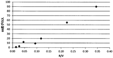
- FIG. 1 is a graph showing the relationship between R / V and 60 degree gloss in the antiglare film produced in the example.
- the lower limit of R / V necessary for producing an antiglare film having high antiglare property and contrast may be 0.01 or more, preferably 0.05 or more, more preferably 0.00. It may be 1 or more (particularly 0.15 or more). Further, in order to produce an antiglare film having a high degree of antiglare property and contrast, the lower limit of R / V may exceed 0.19, preferably exceeds 0.20, and exceeds 0.21. Is more preferable. If R / V is too small, the contrast may decrease. On the other hand, the upper limit of R / V should just be less than 0.35, and less than 0.31 is preferable. If R / V is too high, the antiglare property may be lowered.
- Patent Document 1 Japanese Patent No. 5513388
- Patent Document 1 Japanese Patent No. 5513388
- the necessary antiglare film is selected for high production.
- a calibration curve is created by measuring the gloss and R / V of a plurality of uneven surfaces with different gloss, and the R / V is 0.01. The gross lower limit value may be obtained.
- the evaluation step by selecting an antiglare film that exceeds the gloss lower limit, the uneven structure forming step for forming the uneven structure on the surface of the antiglare film and the evaluation step can be performed continuously.
- the measurement angle of gloss is not particularly limited, and can be selected according to the glossiness of the uneven surface, and examples thereof include 20 degrees, 45 degrees, 60 degrees, 75 degrees, and 85 degrees. Of these measurement angles, 60 degrees is preferable because the measurement range is wide and easy to control.
- the gloss can select a gloss corresponding to the R / V range. For example, the lower limit of 60 degree gloss may exceed 45%, preferably exceed 50%, and more preferably exceed 52%. . On the other hand, the upper limit of 60 degree gloss should just be less than 92%, and less than 80% is preferable.
- gloss such as 60 degree gloss can be measured using a gloss meter (“IG-320” manufactured by Horiba, Ltd.) in accordance with JIS K7105.
- the manufacturing method of this invention may include the uneven
- the said evaluation process can be performed inline, an uneven
- the material of the antiglare film that forms the concavo-convex structure on the surface is not particularly limited as long as it is transparent, and is made of an inorganic material such as glass, an organic material such as a resin component, an inorganic material and an organic material. Any combination may be used, but from the viewpoint of productivity and the like, a material containing a resin component (a resin component such as a thermoplastic resin or a curable resin) is usually preferable.
- the method for forming the concavo-convex structure on the surface is not particularly limited as long as it is a method capable of imparting the concavo-convex structure to the surface of the anti-glare film, and can be appropriately selected according to the material of the anti-glare film,
- a method of curing a curable composition containing a curable resin for example, a method of curing a curable composition containing fine particles by projecting fine particles, the above-described curable composition containing a phase-separable resin component
- a method of curing after phase separation of the resin component) A method of curing after phase separation of the resin component
- a method of transferring using a mold having a concavo-convex structure on the surface a method of forming a concavo-convex structure by cutting (for example, cutting using a laser, etc.)
- Examples thereof include a method for forming a concavo-convex structure by polishing (for example, a sand blast method and
- a method of curing a curable composition containing a curable resin is preferable because an antiglare film having a concavo-convex structure on the surface can be produced with high productivity. For example, curing on a support is possible.
- coating an adhesive composition and drying may be sufficient.
- a support formed of a transparent material is preferable because it can be used as it is as a base layer of an antiglare film.
- the transparent material may be an inorganic material such as glass, but organic materials such as cellulose derivatives, polyesters, polyamides, polyimides, polycarbonates, (meth) acrylic polymers are widely used from the viewpoint of strength and moldability.
- a film formed by (especially an unstretched film) is preferred.
- the curable resin may be either a thermosetting resin or a photocurable resin, but a (meth) acrylic photocurable resin is generally used from the viewpoint of productivity.
- (meth) acrylic photocurable resins include polyfunctional (meth) acrylates [for example, pentaerythritol tetra (meth) acrylate, dipentaerythritol penta (meth) acrylate, dipentaerythritol hexa (meth) acrylate, etc.
- the curable composition may further contain fine particles and polymer components, a reaction initiator, and a conventional additive, which will be described later.
- the curable composition is in a liquid state and usually contains a solvent capable of dissolving the curable composition.
- a coating method for example, a roll coater, an air knife coater, a blade coater, a rod coater, a reverse coater, a bar coater, a comma coater, a dip squeeze coater, a die coater, a gravure coater, a micro gravure coater, a silk screen coater.
- a bar coater method and the gravure coater method are widely used. If necessary, the coating solution may be applied a plurality of times.
- the drying temperature is, for example, about 0 to 120 ° C., preferably about 30 to 110 ° C., more preferably about 50 to 105 ° C. (especially 60 to 100 ° C.).
- the drying time is, for example, about 0.1 to 10 minutes, preferably about 0.3 to 5 minutes, and more preferably about 0.5 to 3 minutes.
- the curing method may be any method that imparts actinic rays (ultraviolet rays, electron beams, etc.) or heat, and may be combined with heating, light irradiation, etc., depending on the type of curable resin.
- the heating temperature can be selected from an appropriate range, for example, about 50 to 150 ° C.
- the light irradiation can be selected according to the type of the photocuring component or the like, and usually ultraviolet rays, electron beams, etc. can be used.
- a general-purpose exposure source is usually an ultraviolet irradiation device.
- a Deep UV lamp for example, in the case of ultraviolet rays, a Deep UV lamp, a low-pressure mercury lamp, a high-pressure mercury lamp, an ultrahigh-pressure mercury lamp, a halogen lamp, a laser light source (light source such as a helium-cadmium laser or an excimer laser) can be used.
- Irradiation light amount irradiation energy
- the thickness of the coating film for example, 10 ⁇ 10000mJ / cm 2, preferably 20 ⁇ 5000mJ / cm 2, more preferably 30 ⁇ 3000mJ / cm 2 approximately. If necessary, the light irradiation may be performed in an inert gas atmosphere.
- a concavo-convex structure may be formed on the surface by curing the curable composition with the fine particles protruding from the surface.
- the fine particles include inorganic fine particles such as silica particles, titania particles, zirconia particles, and alumina particles, copolymer particles of (meth) acrylic monomers and styrene monomers, and crosslinked (meth) acrylic heavy particles. Examples thereof include organic particles such as coalescence particles and crosslinked styrene resin particles. These fine particles can be used alone or in combination of two or more. Among these, crosslinked (meth) acrylic polymer particles are widely used.
- the average particle size of the fine particles can be selected according to the required uneven structure, and is, for example, about 1 to 10 ⁇ m, preferably 2 to 8 ⁇ m, more preferably about 3 to 5 ⁇ m.
- the proportion of the fine particles is, for example, about 1 to 30 parts by weight, preferably 2 to 20 parts by weight, and more preferably about 5 to 10 parts by weight with respect to 100 parts by weight of the curable resin.
- a method using the fine particles for example, a method described in Japanese Patent No. 5513388 can be used.
- phase separation spinodal decomposition wet spinodal decomposition is performed as the concentration is increased in the process of evaporating or removing the solvent from the liquid phase of the composition containing the resin component and the solvent that can be separated by drying, etc.
- Phase separation may occur, and a surface irregularity structure (phase separation structure) having a relatively regular interphase distance may be formed.
- the combination of resin components capable of phase separation may be a combination of the photocurable resins, a combination of the photocurable resin component and a polymer component (thermoplastic resin), or a combination of polymer components.
- (meth) acrylic polymer for example, polymethyl methacrylate, (meth) acrylic polymer having a polymerizable group, etc.
- cellulose esters cellulose acetate C 3 -3 such as cellulose acetate propionate 4 acylate, etc.
- polyester urethane-modified polyester, etc.
- Acrylic polymer having a polymerizable group “Cyclomer P” manufactured by Daicel Ornex Co., Ltd.
- Nano-silica-containing acrylic ultraviolet (UV) curable compound “UVHC7800G” manufactured by Momentive Performance Materials Japan GK Silicone acrylate: “EB1360” manufactured by Daicel Ornex Co., Ltd.
- Urethane acrylate “UA-53H” manufactured by Shin-Nakamura Chemical Co., Ltd.
- Dipentaerythritol hexaacrylate “DPHA” manufactured by Daicel Ornex Co., Ltd.
- Silica particle-containing acrylic resin compound “Z-757-4RL” manufactured by Aika Industry Co., Ltd.
- Acrylic resin compound “Z-757-4CL” manufactured by Aika Industry Co., Ltd.
- Fluorine-based compound A having a polymerizable group “KY-1203” manufactured by Shin-Etsu Chemical Co., Ltd.
- Fluorine compound B having a polymerizable group “Fuategent 602A” manufactured by Neos Co., Ltd.
- Photoinitiator A “Irgacure 184” manufactured by BASF Japan
- Photoinitiator B “Irgacure 907” manufactured by BASF Japan
- Polyethylene terephthalate (PET) film “Diafoil” manufactured by Mitsubishi Plastics, Inc.
- PET Polyethylene terephthalate
- TAC Cellulose triacetate
- An anti-glare film back surface (surface with no concavo-convex structure, surface opposite to the viewer side) is attached to a flat black acrylic plate with no concavo-convex or warp via a transparent adhesive to produce a sample for evaluation. did.
- the evaluation sample was installed in a measuring apparatus, and a light beam was incident on the surface of the evaluation sample on the antiglare film side at an angle of 45 degrees from the normal of the surface.
- 45 degrees which is the regular reflection direction of incident light was defined as the diffuse regular reflection direction
- the reflection intensity in the diffuse regular reflection direction was defined as R.
- Diffuse reflection intensity is obtained by scanning the light receiver at a time in the range of -45 degrees to +45 degrees with respect to the diffuse regular reflection direction for the light that is incident on the antiglare film surface of the evaluation sample and diffusely reflected.
- V the sum was defined as V.
- GP-200 manufactured by Murakami Color Research Laboratory Co., Ltd. was used.
- Production example 1 of antiglare film 12.5 parts by weight of an acrylic polymer having a polymerizable group, 4 parts by weight of cellulose acetate propionate, 150 parts by weight of a nanosilica-containing acrylic UV curable compound, 1 part by weight of silicone acrylate, 1 part by weight of photoinitiator A, 1 part by weight of photoinitiator B was dissolved in a mixed solvent of 81 parts by weight of methyl ethyl ketone, 24 parts by weight of 1-butanol and 13 parts by weight of 1-methoxy-2-propanol. This solution was cast on a PET film using a wire bar # 20, and then left in an oven at 80 ° C.
- the coating layer was irradiated with ultraviolet rays from a high-pressure mercury lamp for about 5 seconds and subjected to UV curing treatment to obtain an antiglare film A (hard coat film).
- Production example 2 of antiglare film 15.0 parts by weight of an acrylic polymer having a polymerizable group, 3 parts by weight of cellulose acetate propionate, 150 parts by weight of a nanosilica-containing acrylic UV curable compound, 1 part by weight of silicone acrylate, 1 part by weight of photoinitiator A, 1 part by weight of photoinitiator B was dissolved in a mixed solvent of 101 parts by weight of methyl ethyl ketone and 24 parts by weight of 1-butanol. This solution was cast on a PET film using a wire bar # 20, and then left in an oven at 80 ° C. for 1 minute to evaporate the solvent to form a coat layer having a thickness of about 9 ⁇ m. Then, the coating layer was irradiated with ultraviolet rays from a high-pressure mercury lamp for about 5 seconds and UV-cured to obtain an antiglare film B.
- Production example 3 of antiglare film A solution obtained by mixing 77 parts of an acrylic resin compound containing silica particles and 155 parts of an acrylic resin compound was cast on a TAC film using a wire bar # 10, and then left in an oven at 100 ° C. for 1 minute. Then, the solvent was evaporated to form a coat layer having a thickness of about 6 ⁇ m. Then, the coating layer was irradiated with ultraviolet rays from a high-pressure mercury lamp for about 5 seconds and UV-cured to obtain an antiglare film C.
- Production example 4 of antiglare film 12.5 parts by weight of an acrylic polymer having a polymerizable group, 5.5 parts by weight of cellulose acetate propionate, 149.2 parts by weight of a nanosilica-containing acrylic UV curable compound, a fluorine-based compound B 0 having a polymerizable group .1 part by weight, 1 part by weight of photoinitiator A, 1 part by weight of photoinitiator B were dissolved in a mixed solvent of 129 parts by weight of methyl ethyl ketone, 24 parts by weight of 1-butanol and 13 parts by weight of 1-methoxy-2-propanol. did.
- This solution was cast on a PET film using a wire bar # 16, and then left in an oven at 80 ° C. for 1 minute to evaporate the solvent to form a coating layer having a thickness of about 7 ⁇ m. Then, the coating layer was irradiated with ultraviolet rays from a high-pressure mercury lamp for about 5 seconds and subjected to UV curing treatment to obtain an antiglare film D.
- Antiglare film production example 5 50 parts by weight of an acrylic polymer having a polymerizable group, 4 parts by weight of cellulose acetate propionate, 76 parts by weight of urethane acrylate, 1 part by weight of silicone acrylate, 1 part by weight of photoinitiator A, and 1 part by weight of photoinitiator B Then, it was dissolved in a mixed solvent of 176 parts by weight of methyl ethyl ketone and 28 parts by weight of 1-butanol. This solution was cast on a PET film using a wire bar # 18, and then left in an oven at 80 ° C. for 1 minute to evaporate the solvent to form a coating layer having a thickness of about 9 ⁇ m. Then, the coating layer was irradiated with ultraviolet rays from a high-pressure mercury lamp for about 5 seconds and subjected to UV curing treatment to obtain an antiglare film E.
- the coating layer was irradiated with ultraviolet rays from a high-pressure mercury lamp for about 5 seconds and UV-cured to obtain an antiglare film F.
- Production example 7 of antiglare film Acrylic polymer having a polymerizable group 5.7 parts by weight, cellulose acetate propionate 1.2 parts by weight, dipentaerythritol hexaacrylate 4 parts by weight, silicone acrylate 2.77 parts by weight, photoinitiator A 0.5
- the parts by weight were dissolved in a mixed solvent of 25 parts by weight of methyl ethyl ketone and 12.2 parts by weight of 1-butanol.
- This solution was cast on a PET film using a wire bar # 24, and then left in an oven at 80 ° C. for 1 minute to evaporate the solvent to form a coat layer having a thickness of about 7 ⁇ m.
- the coating layer was irradiated with ultraviolet rays from a high-pressure mercury lamp for about 5 seconds and subjected to UV curing treatment to obtain an antiglare film G.
- Table 1 shows the results of measuring the diffuse reflection intensity of the obtained antiglare films A to G to calculate R / V, and further measuring the transmission sharpness and 60 degree gloss.
- R / V and 60 degree gloss show a correlation. Therefore, the R / V value can be derived from the 60 degree gloss value.
- Table 1 no correlation was found between R / V and transmission sharpness.
- the manufacturing method of the present invention includes various display devices such as a liquid crystal display (LCD) device, a cathode ray tube display device, an organic or inorganic electroluminescence (EL) display, a field emission display (FED), a surface electric field display (SED), It can be used for the production of an antiglare film used in display devices such as a rear projection television display, a plasma display, and a display device with a touch panel.
- LCD liquid crystal display
- EL organic or inorganic electroluminescence
- FED field emission display
- SED surface electric field display
Landscapes
- Physics & Mathematics (AREA)
- General Physics & Mathematics (AREA)
- Optics & Photonics (AREA)
- General Health & Medical Sciences (AREA)
- Analytical Chemistry (AREA)
- Biochemistry (AREA)
- Chemical & Material Sciences (AREA)
- Life Sciences & Earth Sciences (AREA)
- Immunology (AREA)
- Pathology (AREA)
- Health & Medical Sciences (AREA)
- Engineering & Computer Science (AREA)
- Mechanical Engineering (AREA)
- Optical Elements Other Than Lenses (AREA)
- Shaping Of Tube Ends By Bending Or Straightening (AREA)
Abstract
凹凸構造を有する表面のグロスを測定して、拡散反射強度の総和Vに対する拡散正反射強度Rの比であるR/V(式中、拡散正反射強度Rは、防眩フィルムの凹凸構造を有する表面に向けて、法線から45度の角度で可視光線を照射した際の拡散性反射方向で、変角光度計により開口角1度で測定した拡散反射強度であり、拡散反射強度の総和Vは、防眩フィルムの凹凸構造を有する表面に向けて、法線から45度の角度で可視光線を照射した際の拡散性反射方向に対して、-45度~+45度まで0度を含む1度毎に、変角光度計により開口角1度で測定した拡散反射強度の総和である)を評価して、防眩フィルムを製造する。前記方法により、高い生産性で、防眩性及びコントラストが高い防眩フィルムを製造できる。
Description
本発明は、防眩性とコントラストとのバランスに優れた防眩フィルムを選別しながら連続的に製造する方法に関する。
液晶表示装置(LCD)や有機エレクトロルミネッセンス(EL)表示装置(OLED)の各種画像表示装置では、表面反射光を散乱させて、外部光源などの映り込みを防止して視認性を向上させるための防眩フィルムが表示画面に積層されている。しかし、防眩フィルムの光散乱機能が強すぎると、画像のコントラストが低下して、鮮明な画像の表示が困難となる。一方、近年では、LCDやOLEDにおいて、ディスプレイの高精細化が進んでおり、防眩性とコントラストとを両立できる防眩フィルムが求められている。このような防眩フィルムに要求される両特性は、両立が困難な特性であるため、同一処方で製造しても、両特性を充足しないロットも発生し、実際の製造では、得られた各フィルムについて光学特性を評価する必要があった。また、両特性を評価する方法としては、従来から、ヘイズ値を調整して評価する方法が知られていたが、必ずしもヘイズ値とコントラストとは相関しなかった。
これに対して、特許第5531388号公報(特許文献1)には、透明基材の少なくとも一方の面に機能層を有し、この機能層の最表面及び/又は内部に拡散要素を有する光学シートの製造方法において、所定の角度で測定した拡散反射強度の総和に対する拡散正反射強度の比が0.19を超えるように制御することにより、コントラストに優れた光学シートを安定して製造する方法が開示されている。
しかし、この方法では、前記反射強度比を測定するためには、変角光度計を用いてオフラインで検査する必要あるが、変角光度計は、静止した状態で測定する必要があるため、製造装置内での連続製造はできず、生産性が低かった。
従って、本発明の目的は、高い生産性で、目的とする防眩性及びコントラストを有する防眩フィルムを製造する方法を提供することにある。
本発明者は、前記課題を達成するため鋭意検討の結果、所定の角度で測定した拡散反射強度の総和Vに対する拡散正反射強度Rの比であるR/Vとグロスとの間に相関関係があり、グロスを測定して防眩フィルムの特性を評価することにより、高い生産性で、防眩性及びコントラストが高い防眩フィルムを製造できることを見出し、本発明を完成した。
すなわち、本発明の防眩フィルムの製造方法は、凹凸構造を有する表面のグロスを測定して、拡散反射強度の総和Vに対する拡散正反射強度Rの比であるR/V(式中、拡散正反射強度Rは、防眩フィルムの凹凸構造を有する表面に向けて、法線から45度の角度で可視光線を照射した際の拡散性反射方向で、変角光度計により開口角1度で測定した拡散反射強度であり、拡散反射強度の総和Vは、防眩フィルムの凹凸構造を有する表面に向けて、法線から45度の角度で可視光線を照射した際の拡散性反射方向に対して、-45度~+45度まで0度を含む1度毎に、変角光度計により開口角1度で測定した拡散反射強度の総和である)を評価する評価工程を含む。本発明の製造方法では、R/Vが0.01となるグロス下限値を予め求め、評価工程において、前記グロス下限値を超える防眩フィルムを選別してもよい。前記評価工程において、60度グロスを測定してもよい。60度グロスを測定する場合、前記評価工程において、60度グロスが45%を超える防眩フィルムを選別してもよい。本発明の製造方法は、防眩フィルム表面の凹凸構造を形成する凹凸構造形成工程をさらに含み、前記凹凸構造形成工程と評価工程とを連続的に行ってもよい。前記凹凸構造形成工程において、硬化性樹脂を含む硬化性組成物を硬化させてもよい。前記硬化性組成物は、微粒子を含んでいてもよい。前記硬化性組成物は、相分離可能な樹脂成分を含んでいてもよい。
本発明では、所定の角度で測定した拡散反射強度の総和Vに対する拡散正反射強度Rの比であるR/Vとグロスとの間に相関関係があり、グロスを測定して防眩フィルムの特性を評価するため、インライン(稼働している製造装置の連続工程)での検査が可能となり、高い生産性で、目的とする防眩性及びコントラストを有する防眩フィルムを製造できる。そのため、防眩性及びコントラストが高い防眩フィルムや防眩性及びコントラストのバランスに優れた防眩フィルムを検査しながら連続生産できる。
[評価工程]
本発明の防眩フィルムの製造方法は、凹凸構造を有する表面(凹凸表面)のグロスを測定して、拡散反射強度の総和Vに対する拡散正反射強度Rの比であるR/Vを評価する評価工程を含む。本発明では、前記R/Vとグロスとの間に相関関係があることを見出し、R/Vを評価する代わりに、グロスを評価して、防眩フィルムの特性を評価できる。グロスは、静止していない運転中の連続工程(インライン)でも測定できるため、オフラインで検査する必要があったR/Vを測定する評価工程に比べて、生産性を格段に向上できる。
本発明の防眩フィルムの製造方法は、凹凸構造を有する表面(凹凸表面)のグロスを測定して、拡散反射強度の総和Vに対する拡散正反射強度Rの比であるR/Vを評価する評価工程を含む。本発明では、前記R/Vとグロスとの間に相関関係があることを見出し、R/Vを評価する代わりに、グロスを評価して、防眩フィルムの特性を評価できる。グロスは、静止していない運転中の連続工程(インライン)でも測定できるため、オフラインで検査する必要があったR/Vを測定する評価工程に比べて、生産性を格段に向上できる。
本発明では、高い防眩性及びコントラストを有する防眩フィルムを製造するために必要なR/Vの下限は0.01以上であってもよく、好ましくは0.05以上、さらに好ましくは0.1以上(特に、0.15以上)であってもよい。さらに高度な防眩性及びコントラストを有する防眩フィルムを製造するためには、R/Vの下限は、0.19を超えてもよく、0.20を超えるのが好ましく、0.21を超えるのがさらに好ましい。R/Vが小さすぎると、コントラストが低下する虞がある。一方、R/Vの上限は、0.35未満であればよく、0.31未満が好ましい。R/Vが高すぎると、防眩性が低下する虞がある。
R/Vの測定方法としては、特許文献1(特許第5531388号公報)に記載の方法を利用でき、詳細には、後述する実施例に記載の方法で測定できる。
本発明では、防眩フィルムに必要なR/Vを前記範囲から選択して決定した後、R/Vの範囲に対応するグロスを評価することにより、必要な防眩フィルムを選別し、高い生産性で防眩フィルムを製造できる。例えば、R/Vが0.01以上の防眩シートを製造する場合、グロスの異なる複数の凹凸表面のグロス及びR/Vを測定して検量線を作成し、R/Vが0.01となるグロス下限値を求めてもよい。評価工程において、前記グロス下限値を超える防眩フィルムを選別することにより、防眩フィルム表面の凹凸構造を形成する凹凸構造形成工程と評価工程とを連続的に行うことができる。
グロス(光沢度)の測定角度は、特に限定されず、凹凸表面の光沢度に応じて選択でき、例えば、20度、45度、60度、75度、85度などが挙げられる。これらの測定角度のうち、測定範囲が広く、制御し易い点から、60度が好ましい。グロスは、前記R/Vの範囲と対応するグロスを選択でき、例えば、60度グロスの下限は、45%を超えてもよく、50%を超えるのが好ましく、52%を超えるのがさらに好ましい。一方、60度グロスの上限は、92%未満であればよく、80%未満が好ましい。
なお、本明細書及び特許請求の範囲では、60度グロスなどのグロスは、JIS K7105に準拠して、グロスメーター((株)堀場製作所製「IG-320」)を用いて測定できる。
[凹凸構造形成工程]
本発明の製造方法は、前記評価工程の前工程として、凹凸構造形成工程を含んでいてもよい。本発明では、前記評価工程をインラインで行えるため、凹凸構造形成工程と、評価工程とを連続工程とすることができる。
本発明の製造方法は、前記評価工程の前工程として、凹凸構造形成工程を含んでいてもよい。本発明では、前記評価工程をインラインで行えるため、凹凸構造形成工程と、評価工程とを連続工程とすることができる。
凹凸構造形成工程において、表面に凹凸構造を形成する防眩フィルムの材料は、透明であれば、特に限定されず、ガラスなどの無機材料、樹脂成分などの有機材料、無機材料と有機材料との組み合わせのいずれであってもよいが、生産性などの点から、通常、樹脂成分(熱可塑性樹脂、硬化性樹脂などの樹脂成分)を含む材料が好ましい。
凹凸構造形成工程において、表面に凹凸構造を形成する方法としては、防眩フィルムの表面に凹凸構造を付与できる方法であれば、特に限定されず、防眩フィルムの材質に応じて適宜選択でき、例えば、硬化性樹脂を含む硬化性組成物を硬化させる方法(例えば、微粒子を含む硬化性組成物を、微粒子を突出させて硬化する方法、相分離可能な樹脂成分を含む硬化性組成物の前記樹脂成分を相分離させた後に硬化する方法など)、表面に凹凸構造を有する型を用いて転写する方法、切削加工によって凹凸構造を形成する方法(例えば、レーザーなどを利用した切削加工など)、研磨によって凹凸構造を形成する方法(例えば、サンドブラスト法やビーズショット法など)、エッチングによって凹凸構造を形成する方法などが挙げられる。
これらの方法のうち、表面に凹凸構造を有する防眩フィルムを高い生産性で製造できる点から、硬化性樹脂を含む硬化性組成物を硬化する方法が好ましく、例えば、支持体の上に、硬化性組成物を塗布して乾燥した後、硬化させる方法であってもよい。
支持体としては、そのまま防眩フィルムの基材層として利用できる点から、透明材料で形成された支持体が好ましい。透明材料は、ガラスなどの無機材料であってもよいが、強度や成形性などの点から、セルロース誘導体、ポリエステル、ポリアミド、ポリイミド、ポリカーボネート、(メタ)アクリル系重合体などの有機材料が汎用される。これらのうち、機械的特性や透明性などのバランスに優れる点から、セルローストリアセテート(TAC)などのセルロースアセテートで形成されたフィルム、ポリエチレンテレフタレート(PET)、ポリエチレンナフタレート(PEN)などのポリアルキレンアリレートで形成されたフィルム(特に未延伸フィルム)が好ましい。
硬化性樹脂は、熱硬化性樹脂、光硬化性樹脂のいずれであってもよいが、生産性などの点から、(メタ)アクリル系光硬化性樹脂が汎用される。(メタ)アクリル系光硬化性樹脂としては、例えば、多官能性(メタ)アクリレート[例えば、ペンタエリスリトールテトラ(メタ)アクリレート、ジペンタエリスリトールペンタ(メタ)アクリレート、ジペンタエリスリトールヘキサ(メタ)アクリレートなどの2~8程度の重合性基を有する(メタ)アクリレートなど]、エポキシ(メタ)アクリレート、ポリエステル(メタ)アクリレート、ウレタン(メタ)アクリレート、シリコーン(メタ)アクリレート、重合性基を有する(メタ)アクリル系樹脂などが挙げられる。
硬化性組成物は、硬化性樹脂に加えて、後述する微粒子やポリマー成分、反応開始剤、慣用の添加剤をさらに含んでいてもよい。また、硬化性組成物は、液状であり、通常、硬化性組成物を溶解可能な溶媒を含んでいる。
塗布方法としては、慣用の方法、例えば、ロールコーター、エアナイフコーター、ブレードコーター、ロッドコーター、リバースコーター、バーコーター、コンマコーター、ディップ・スクイズコーター、ダイコーター、グラビアコーター、マイクログラビアコーター、シルクスクリーンコーター法、ディップ法、スプレー法、スピナー法などが挙げられる。これらの方法のうち、バーコーター法やグラビアコーター法などが汎用される。なお、必要であれば、塗布液は複数回に亘り塗布してもよい。
乾燥温度は、例えば0~120℃、好ましくは30~110℃、さらに好ましくは50~105℃(特に60~100℃)程度である。乾燥時間は、例えば0.1~10分、好ましくは0.3~5分、さらに好ましくは0.5~3分程度である。
硬化方法は、活性光線(紫外線、電子線など)や熱などを付与する方法であればよく、硬化性樹脂の種類に応じて、加熱、光照射などを組み合わせてもよい。
加熱温度は、適当な範囲、例えば50~150℃程度から選択できる。光照射は、光硬化成分などの種類に応じて選択でき、通常、紫外線、電子線などが利用できる。汎用的な露光源は、通常、紫外線照射装置である。
光源としては、例えば、紫外線の場合は、Deep UV ランプ、低圧水銀ランプ、高圧水銀ランプ、超高圧水銀ランプ、ハロゲンランプ、レーザー光源(ヘリウム-カドミウムレーザー、エキシマレーザーなどの光源)などを利用できる。照射光量(照射エネルギー)は、塗膜の厚みにより異なり、例えば10~10000mJ/cm2、好ましくは20~5000mJ/cm2、さらに好ましくは30~3000mJ/cm2程度である。光照射は、必要であれば、不活性ガス雰囲気中で行ってもよい。
このような硬化性組成物を硬化する方法において、表面に凹凸構造を形成する方法としては、前記硬化性組成物に微粒子を配合し、微粒子を突出させて硬化する方法(微粒子を利用する方法)、前記硬化性組成物に相分離可能な樹脂成分を配合し、この樹脂成分を相分離させた後に硬化する方法(相分離を利用する方法)などが挙げられる。
微粒子を利用する方法では、表面から微粒子が突出した状態で、硬化性組成物を硬化させることにより、表面に凹凸構造を形成してもよい。微粒子としては、例えば、シリカ粒子、チタニア粒子、ジルコニア粒子、アルミナ粒子などの無機微粒子、(メタ)アクリル系単量体とスチレン系単量体との共重合体粒子、架橋(メタ)アクリル系重合体粒子、架橋スチレン系樹脂粒子などの有機微粒子などが挙げられる。これらの微粒子は、単独で又は二種以上組み合わせて使用できる。これらのうち、架橋(メタ)アクリル系重合体粒子などが汎用される。微粒子の平均粒径は、要求される凹凸構造に応じて選択でき、例えば1~10μm、好ましくは2~8μm、さらに好ましくは3~5μm程度である。微粒子の割合は、硬化性樹脂100重量部に対して、例えば1~30重量部、好ましくは2~20重量部、さらに好ましくは5~10重量部程度である。微粒子を利用する方法としては、例えば、特許第5531388号公報に記載の方法なども利用できる。
相分離を利用する方法では、相分離可能な樹脂成分及び溶媒を含む組成物の液相から、溶媒を乾燥などにより蒸発又は除去する過程で、濃度の濃縮に伴って、スピノーダル分解湿式スピノーダル分解)による相分離が生じ、相間距離が比較的規則的な表面凹凸構造(相分離構造)を形成してもよい。相分離可能な樹脂成分の組み合わせとしては、前記光硬化性樹脂同士の組み合わせ、前記光硬化性樹脂成分とポリマー成分(熱可塑性樹脂)との組み合わせ、ポリマー成分同士の組み合わせのいずれであってもよく、例えば、(メタ)アクリル系重合体(例えば、ポリメタクリル酸メチル、重合性基を有する(メタ)アクリル系重合体など)と、セルロースエステル類(セルロースアセテートプロピオネートなどのセルロースアセテートC3-4アシレートなど)又はポリエステル(ウレタン変性ポリエステルなど)との組み合わせであってもよい。相分離を利用する方法としては、例えば、特開2007-187746、特開2008-225195、特開2009-267775、特開2011-175601、特開2014-85371号公報に記載の方法なども利用できる。
以下に、実施例に基づいて本発明をより詳細に説明するが、本発明はこれらの実施例によって限定されるものではない。実施例及び比較例で用いた原料は以下の通りであり、得られた防眩フィルムを以下の方法で評価した。
[原料]
重合性基を有するアクリル系重合体:ダイセル・オルネクス(株)製「サイクロマーP」
セルロースアセテートプロピオネート:イーストマン社製「CAP-482-20」、アセチル化度=2.5%、プロピオニル化度=46%、ポリスチレン換算数平均分子量75000
ナノシリカ含有アクリル系紫外線(UV)硬化性化合物:モメンティブ・パフォーマンス・マテリアルズ・ジャパン合同会社製「UVHC7800G」
シリコーンアクリレート:ダイセル・オルネクス(株)製「EB1360」
ウレタンアクリレート:新中村化学工業(株)製「UA-53H」
ジペンタエリスリトールヘキサアクリレート:ダイセル・オルネクス(株)製「DPHA」
シリカ粒子含有アクリル系樹脂配合物:アイカ工業(株)製「Z-757-4RL」
アクリル系樹脂配合物:アイカ工業(株)製「Z-757-4CL」
重合性基を有するフッ素系化合物A:信越化学工業(株)製「KY-1203」
重合性基を有するフッ素系化合物B:(株)ネオス製「フタージェント602A」
光開始剤A:BASFジャパン(株)製「イルガキュア184」
光開始剤B:BASFジャパン(株)製「イルガキュア907」
ポリエチレンテレフタレート(PET)フィルム:三菱樹脂(株)製「ダイアホイル」
セルローストリアセテート(TAC)フィルム:富士フイルム(株)製「フジタックTG60UL」。
重合性基を有するアクリル系重合体:ダイセル・オルネクス(株)製「サイクロマーP」
セルロースアセテートプロピオネート:イーストマン社製「CAP-482-20」、アセチル化度=2.5%、プロピオニル化度=46%、ポリスチレン換算数平均分子量75000
ナノシリカ含有アクリル系紫外線(UV)硬化性化合物:モメンティブ・パフォーマンス・マテリアルズ・ジャパン合同会社製「UVHC7800G」
シリコーンアクリレート:ダイセル・オルネクス(株)製「EB1360」
ウレタンアクリレート:新中村化学工業(株)製「UA-53H」
ジペンタエリスリトールヘキサアクリレート:ダイセル・オルネクス(株)製「DPHA」
シリカ粒子含有アクリル系樹脂配合物:アイカ工業(株)製「Z-757-4RL」
アクリル系樹脂配合物:アイカ工業(株)製「Z-757-4CL」
重合性基を有するフッ素系化合物A:信越化学工業(株)製「KY-1203」
重合性基を有するフッ素系化合物B:(株)ネオス製「フタージェント602A」
光開始剤A:BASFジャパン(株)製「イルガキュア184」
光開始剤B:BASFジャパン(株)製「イルガキュア907」
ポリエチレンテレフタレート(PET)フィルム:三菱樹脂(株)製「ダイアホイル」
セルローストリアセテート(TAC)フィルム:富士フイルム(株)製「フジタックTG60UL」。
[拡散反射強度の測定]
防眩フィルムの裏面(凹凸構造を有さない面、観察者側と反対側の面)を、透明粘着剤を介して凹凸や反りのない平坦な黒アクリル板に貼付して評価用サンプルを作製した。次に、評価用サンプルを測定装置に設置し、評価用サンプルの防眩フィルム側の面に対し、面の法線から45度の角度より光束を入射した。なお、入射光の正反射方向である45度を拡散正反射方向と定義し、拡散正反射方向における反射強度をRと定めた。光束が評価用サンプルの防眩フィルム面に入射し拡散反射した光を、拡散正反射方向に対し-45度~+45度までの範囲で、1度ごとに受光器を走査することにより拡散反射強度を測定し、その総和をVと定義した。また、拡散反射強度を測定する装置については、(株)村上色彩研究所製「GP-200」を使用した。
防眩フィルムの裏面(凹凸構造を有さない面、観察者側と反対側の面)を、透明粘着剤を介して凹凸や反りのない平坦な黒アクリル板に貼付して評価用サンプルを作製した。次に、評価用サンプルを測定装置に設置し、評価用サンプルの防眩フィルム側の面に対し、面の法線から45度の角度より光束を入射した。なお、入射光の正反射方向である45度を拡散正反射方向と定義し、拡散正反射方向における反射強度をRと定めた。光束が評価用サンプルの防眩フィルム面に入射し拡散反射した光を、拡散正反射方向に対し-45度~+45度までの範囲で、1度ごとに受光器を走査することにより拡散反射強度を測定し、その総和をVと定義した。また、拡散反射強度を測定する装置については、(株)村上色彩研究所製「GP-200」を使用した。
[60度グロス]
JlS K7105に準拠してグロスメーター((株)掘場製作所製「IG-320」)を用いて角度60度で測定した。
JlS K7105に準拠してグロスメーター((株)掘場製作所製「IG-320」)を用いて角度60度で測定した。
[透過鮮明度]
防眩フィルムの写像鮮明度を、写像測定器(スガ試験機(株)製、商品名「ICM-1T」)を用いて、JIS K7105に基づき、フィルムの製膜方向と光学櫛の櫛歯の方向とが平行になるようにフィルムを設置して測定を行った。写像測定器の光学櫛のうち、0.5mm幅の光学櫛における写像鮮明度を測定した。
防眩フィルムの写像鮮明度を、写像測定器(スガ試験機(株)製、商品名「ICM-1T」)を用いて、JIS K7105に基づき、フィルムの製膜方向と光学櫛の櫛歯の方向とが平行になるようにフィルムを設置して測定を行った。写像測定器の光学櫛のうち、0.5mm幅の光学櫛における写像鮮明度を測定した。
防眩フィルムの製造例1
重合性基を有するアクリル系重合体12.5重量部、セルロースアセテートプロピオネート4重量部、ナノシリカ含有アクリル系UV硬化性化合物150重量部、シリコーンアクリレート1重量部、光開始剤A 1重量部、光開始剤B 1重量部を、メチルエチルケトン81重量部と1-ブタノール24重量部と1-メトキシ-2-プロパノール13重量部との混合溶媒に溶解した。この溶液を、ワイヤーバー#20を用いて、PETフィルム上に流延した後、80℃のオーブン内で1分間放置し、溶媒を蒸発させて厚さ約9μmのコート層を形成させた。そして、コート層に、高圧水銀ランプからの紫外線を約5秒間照射してUV硬化処理し、防眩フィルムA(ハードコートフィルム)を得た。
重合性基を有するアクリル系重合体12.5重量部、セルロースアセテートプロピオネート4重量部、ナノシリカ含有アクリル系UV硬化性化合物150重量部、シリコーンアクリレート1重量部、光開始剤A 1重量部、光開始剤B 1重量部を、メチルエチルケトン81重量部と1-ブタノール24重量部と1-メトキシ-2-プロパノール13重量部との混合溶媒に溶解した。この溶液を、ワイヤーバー#20を用いて、PETフィルム上に流延した後、80℃のオーブン内で1分間放置し、溶媒を蒸発させて厚さ約9μmのコート層を形成させた。そして、コート層に、高圧水銀ランプからの紫外線を約5秒間照射してUV硬化処理し、防眩フィルムA(ハードコートフィルム)を得た。
防眩フィルムの製造例2
重合性基を有するアクリル系重合体15.0重量部、セルロースアセテートプロピオネート3重量部、ナノシリカ含有アクリル系UV硬化性化合物150重量部、シリコーンアクリレート1重量部、光開始剤A 1重量部、光開始剤B 1重量部を、メチルエチルケトン101重量部と1-ブタノール24重量部との混合溶媒に溶解した。この溶液を、ワイヤーバー#20を用いて、PETフィルム上に流延した後、80℃のオーブン内で1分間放置し、溶媒を蒸発させて厚さ約9μmのコート層を形成させた。そして、コート層に、高圧水銀ランプからの紫外線を約5秒間照射してUV硬化処理し、防眩フィルムBを得た。
重合性基を有するアクリル系重合体15.0重量部、セルロースアセテートプロピオネート3重量部、ナノシリカ含有アクリル系UV硬化性化合物150重量部、シリコーンアクリレート1重量部、光開始剤A 1重量部、光開始剤B 1重量部を、メチルエチルケトン101重量部と1-ブタノール24重量部との混合溶媒に溶解した。この溶液を、ワイヤーバー#20を用いて、PETフィルム上に流延した後、80℃のオーブン内で1分間放置し、溶媒を蒸発させて厚さ約9μmのコート層を形成させた。そして、コート層に、高圧水銀ランプからの紫外線を約5秒間照射してUV硬化処理し、防眩フィルムBを得た。
防眩フィルムの製造例3
シリカ粒子含有アクリル系樹脂配合物77部とアクリル系樹脂配合物155部とを混合した溶液を、ワイヤーバー#10を用いてTACフィルム上に流延した後、100℃のオーブン内で1分間放置し、溶媒を蒸発させて厚さ約6μmのコート層を形成させた。そして、コート層に、高圧水銀ランプからの紫外線を約5秒間照射してUV硬化処理し、防眩フィルムCを得た。
シリカ粒子含有アクリル系樹脂配合物77部とアクリル系樹脂配合物155部とを混合した溶液を、ワイヤーバー#10を用いてTACフィルム上に流延した後、100℃のオーブン内で1分間放置し、溶媒を蒸発させて厚さ約6μmのコート層を形成させた。そして、コート層に、高圧水銀ランプからの紫外線を約5秒間照射してUV硬化処理し、防眩フィルムCを得た。
防眩フィルムの製造例4
重合性基を有するアクリル系重合体12.5重量部、セルロースアセテートプロピオネート5.5重量部、ナノシリカ含有アクリル系UV硬化性化合物149.2重量部、重合性基を有するフッ素系化合物B 0.1重量部、光開始剤A 1重量部、光開始剤B 1重量部を、メチルエチルケトン129重量部と1-ブタノール24重量部と1-メトキシ-2-プロパノール13重量部との混合溶媒に溶解した。この溶液を、ワイヤーバー#16を用いて、PETフィルム上に流延した後、80℃のオーブン内で1分間放置し、溶媒を蒸発させて厚さ約7μmのコート層を形成させた。そして、コート層に、高圧水銀ランプからの紫外線を約5秒間照射してUV硬化処理し、防眩フィルムDを得た。
重合性基を有するアクリル系重合体12.5重量部、セルロースアセテートプロピオネート5.5重量部、ナノシリカ含有アクリル系UV硬化性化合物149.2重量部、重合性基を有するフッ素系化合物B 0.1重量部、光開始剤A 1重量部、光開始剤B 1重量部を、メチルエチルケトン129重量部と1-ブタノール24重量部と1-メトキシ-2-プロパノール13重量部との混合溶媒に溶解した。この溶液を、ワイヤーバー#16を用いて、PETフィルム上に流延した後、80℃のオーブン内で1分間放置し、溶媒を蒸発させて厚さ約7μmのコート層を形成させた。そして、コート層に、高圧水銀ランプからの紫外線を約5秒間照射してUV硬化処理し、防眩フィルムDを得た。
防眩フィルムの製造例5
重合性基を有するアクリル系重合体50重量部、セルロースアセテートプロピオネート4重量部、ウレタンアクリレート76重量部、シリコーンアクリレート1重量部、光開始剤A 1重量部、光開始剤B 1重量部を、メチルエチルケトン176重量部と1-ブタノール28重量部との混合溶媒に溶解した。この溶液を、ワイヤーバー#18を用いて、PETフィルム上に流延した後、80℃のオーブン内で1分間放置し、溶媒を蒸発させて厚さ約9μmのコート層を形成させた。そして、コート層に、高圧水銀ランプからの紫外線を約5秒間照射してUV硬化処理し、防眩フィルムEを得た。
重合性基を有するアクリル系重合体50重量部、セルロースアセテートプロピオネート4重量部、ウレタンアクリレート76重量部、シリコーンアクリレート1重量部、光開始剤A 1重量部、光開始剤B 1重量部を、メチルエチルケトン176重量部と1-ブタノール28重量部との混合溶媒に溶解した。この溶液を、ワイヤーバー#18を用いて、PETフィルム上に流延した後、80℃のオーブン内で1分間放置し、溶媒を蒸発させて厚さ約9μmのコート層を形成させた。そして、コート層に、高圧水銀ランプからの紫外線を約5秒間照射してUV硬化処理し、防眩フィルムEを得た。
防眩フィルムの製造例6
重合性基を有するアクリル系重合体50重量部、セルロースアセテートプロピオネート4重量部、ウレタンアクリレート76重量部、シリコーンアクリレート1重量部、重合性基を有するフッ素系化合物A 1重量部、光開始剤A 1重量部、光開始剤B 1重量部を、メチルエチルケトン176重量部と1-ブタノール28重量部との混合溶媒に溶解した。この溶液を、ワイヤーバー#14を用いて、PETフィルム上に流延した後、80℃のオーブン内で1分間放置し、溶媒を蒸発させて厚さ約6μmのコート層を形成させた。そして、コート層に、高圧水銀ランプからの紫外線を約5秒間照射してUV硬化処理し、防眩フィルムFを得た。
重合性基を有するアクリル系重合体50重量部、セルロースアセテートプロピオネート4重量部、ウレタンアクリレート76重量部、シリコーンアクリレート1重量部、重合性基を有するフッ素系化合物A 1重量部、光開始剤A 1重量部、光開始剤B 1重量部を、メチルエチルケトン176重量部と1-ブタノール28重量部との混合溶媒に溶解した。この溶液を、ワイヤーバー#14を用いて、PETフィルム上に流延した後、80℃のオーブン内で1分間放置し、溶媒を蒸発させて厚さ約6μmのコート層を形成させた。そして、コート層に、高圧水銀ランプからの紫外線を約5秒間照射してUV硬化処理し、防眩フィルムFを得た。
防眩フィルムの製造例7
重合性基を有するアクリル系重合体5.7重量部、セルロースアセテートプロピオネート1.2重量部、ジペンタエリスリトールヘキサアクリレート4重量部、シリコーンアクリレート2.77重量部、光開始剤A 0.5重量部を、メチルエチルケトン25重量部と1-ブタノール12.2重量部との混合溶媒に溶解した。この溶液を、ワイヤーバー#24を用いて、PETフィルム上に流延した後、80℃のオーブン内で1分間放置し、溶媒を蒸発させて厚さ約7μmのコート層を形成させた。そして、コート層に、高圧水銀ランプからの紫外線を約5秒間照射してUV硬化処理し、防眩フィルムGを得た。
重合性基を有するアクリル系重合体5.7重量部、セルロースアセテートプロピオネート1.2重量部、ジペンタエリスリトールヘキサアクリレート4重量部、シリコーンアクリレート2.77重量部、光開始剤A 0.5重量部を、メチルエチルケトン25重量部と1-ブタノール12.2重量部との混合溶媒に溶解した。この溶液を、ワイヤーバー#24を用いて、PETフィルム上に流延した後、80℃のオーブン内で1分間放置し、溶媒を蒸発させて厚さ約7μmのコート層を形成させた。そして、コート層に、高圧水銀ランプからの紫外線を約5秒間照射してUV硬化処理し、防眩フィルムGを得た。
得られた防眩フィルムA~Gの拡散反射強度を測定してR/Vを算出し、さらに透過鮮明度及び60度グロスを測定した結果を表1に示す。

さらに、R/Vと60度グロスとの関係を示す図1から明らかなように、R/Vと60度グロスとは相関関係を示している。そのため、60度グロスの数値から、R/Vの数値を導き出すことができる。これに対して、表1から明らかなように、R/Vと透過鮮明度との間に相関関係は見られなかった。
本発明の製造方法は、種々の表示装置、例えば、液晶表示(LCD)装置、陰極管表示装置、有機又は無機エレクトロルミネッセンス(EL)ディスプレイ、フィールドエミッションディスプレイ(FED)、表面電界ディスプレイ(SED)、リアプロジェクションテレビディスプレイ、プラズマディスプレイ、タッチパネル付き表示装置などの表示装置に利用される防眩フィルムの製造に利用できる。
Claims (8)
- 凹凸構造を有する表面のグロスを測定して、拡散反射強度の総和Vに対する拡散正反射強度Rの比であるR/V(式中、拡散正反射強度Rは、防眩フィルムの凹凸構造を有する表面に向けて、法線から45度の角度で可視光線を照射した際の拡散性反射方向で、変角光度計により開口角1度で測定した拡散反射強度であり、拡散反射強度の総和Vは、防眩フィルムの凹凸構造を有する表面に向けて、法線から45度の角度で可視光線を照射した際の拡散性反射方向に対して、-45度~+45度まで0度を含む1度毎に、変角光度計により開口角1度で測定した拡散反射強度の総和である)を評価する評価工程を含む防眩フィルムの製造方法。
- R/Vが0.01となるグロス下限値を予め求め、評価工程において、前記グロス下限値を超える防眩フィルムを選別する請求項1記載の製造方法。
- 評価工程において、60度グロスを測定する請求項1又は2記載の製造方法。
- 60度グロスが45%を超える防眩フィルムを選別する請求項3記載の製造方法。
- 防眩フィルム表面の凹凸構造を形成する凹凸構造形成工程をさらに含み、前記凹凸構造形成工程と評価工程とを連続的に行う請求項1~4のいずれかに記載の製造方法。
- 凹凸構造形成工程において、硬化性樹脂を含む硬化性組成物を硬化する請求項1~5のいずれかに記載の製造方法。
- 硬化性組成物が微粒子を含む請求項6記載の製造方法。
- 硬化性組成物が相分離可能な樹脂成分を含む請求項6記載の製造方法。
Priority Applications (3)
| Application Number | Priority Date | Filing Date | Title |
|---|---|---|---|
| CN201880028383.XA CN110573914B (zh) | 2017-05-29 | 2018-03-23 | 防眩膜的制造方法 |
| KR1020197035009A KR102192944B1 (ko) | 2017-05-29 | 2018-03-23 | 방현 필름의 제조 방법 |
| US16/492,773 US11624856B2 (en) | 2017-05-29 | 2018-03-23 | Method for manufacturing anti-glare film |
Applications Claiming Priority (2)
| Application Number | Priority Date | Filing Date | Title |
|---|---|---|---|
| JP2017105775A JP6336660B1 (ja) | 2017-05-29 | 2017-05-29 | 防眩フィルムの製造方法 |
| JP2017-105775 | 2017-05-29 |
Publications (1)
| Publication Number | Publication Date |
|---|---|
| WO2018220960A1 true WO2018220960A1 (ja) | 2018-12-06 |
Family
ID=62487527
Family Applications (1)
| Application Number | Title | Priority Date | Filing Date |
|---|---|---|---|
| PCT/JP2018/011637 Ceased WO2018220960A1 (ja) | 2017-05-29 | 2018-03-23 | 防眩フィルムの製造方法 |
Country Status (6)
| Country | Link |
|---|---|
| US (1) | US11624856B2 (ja) |
| JP (1) | JP6336660B1 (ja) |
| KR (1) | KR102192944B1 (ja) |
| CN (1) | CN110573914B (ja) |
| TW (1) | TWI731235B (ja) |
| WO (1) | WO2018220960A1 (ja) |
Cited By (1)
| Publication number | Priority date | Publication date | Assignee | Title |
|---|---|---|---|---|
| JPWO2021065573A1 (ja) * | 2019-09-30 | 2021-04-08 |
Families Citing this family (2)
| Publication number | Priority date | Publication date | Assignee | Title |
|---|---|---|---|---|
| US12468072B2 (en) | 2020-03-05 | 2025-11-11 | Xinmei Fontana Holding (Hong Kong) Limited | Optical film and micro LED display comprising thereof |
| CN113927887B (zh) * | 2021-09-08 | 2024-10-29 | 东莞市光志光电有限公司 | 增光膜的加工方法 |
Citations (5)
| Publication number | Priority date | Publication date | Assignee | Title |
|---|---|---|---|---|
| JP2006170925A (ja) * | 2004-12-20 | 2006-06-29 | Dainippon Printing Co Ltd | 光沢度測定方法および装置 |
| JP2009244305A (ja) * | 2008-03-28 | 2009-10-22 | Lintec Corp | 防眩性ハードコートフィルム及びそれを用いた偏光板 |
| JP2013061636A (ja) * | 2011-08-23 | 2013-04-04 | Mitsubishi Rayon Co Ltd | 防眩性前面板 |
| JP5531388B2 (ja) * | 2008-09-11 | 2014-06-25 | 大日本印刷株式会社 | 光学シートの製造方法 |
| US9022619B2 (en) * | 2009-10-23 | 2015-05-05 | 3M Innovative Properties Company | Optical constructions and method of making the same |
Family Cites Families (8)
| Publication number | Priority date | Publication date | Assignee | Title |
|---|---|---|---|---|
| JPS54145049A (en) | 1978-05-02 | 1979-11-12 | Toshiba Corp | Refrigerat0r |
| JP2003084106A (ja) * | 2001-09-10 | 2003-03-19 | Nippon Sheet Glass Co Ltd | 無機材料からなる凸状膜及びその形成方法 |
| JP4174344B2 (ja) | 2002-03-15 | 2008-10-29 | 日東電工株式会社 | 反射防止フィルム、その製造方法、光学素子および画像表示装置 |
| US8163372B2 (en) * | 2006-08-14 | 2012-04-24 | Dai Nippon Printing Co., Ltd. | Anti-dazzling optical laminate |
| JP2010020267A (ja) * | 2008-06-09 | 2010-01-28 | Sony Corp | 光学フィルムおよびその製造方法、防眩性フィルム、光学層付偏光子、ならびに表示装置 |
| JP5653378B2 (ja) * | 2011-09-27 | 2015-01-14 | 日本製紙株式会社 | 防眩ハードコートフィルム |
| JP5909454B2 (ja) * | 2012-03-30 | 2016-04-26 | 富士フイルム株式会社 | 防眩フィルム、その製造方法、偏光板、及び画像表示装置 |
| JP6059695B2 (ja) * | 2014-09-01 | 2017-01-11 | デクセリアルズ株式会社 | 光学体の製造方法 |
-
2017
- 2017-05-29 JP JP2017105775A patent/JP6336660B1/ja active Active
-
2018
- 2018-03-23 KR KR1020197035009A patent/KR102192944B1/ko active Active
- 2018-03-23 WO PCT/JP2018/011637 patent/WO2018220960A1/ja not_active Ceased
- 2018-03-23 US US16/492,773 patent/US11624856B2/en active Active
- 2018-03-23 CN CN201880028383.XA patent/CN110573914B/zh active Active
- 2018-04-24 TW TW107113861A patent/TWI731235B/zh active
Patent Citations (5)
| Publication number | Priority date | Publication date | Assignee | Title |
|---|---|---|---|---|
| JP2006170925A (ja) * | 2004-12-20 | 2006-06-29 | Dainippon Printing Co Ltd | 光沢度測定方法および装置 |
| JP2009244305A (ja) * | 2008-03-28 | 2009-10-22 | Lintec Corp | 防眩性ハードコートフィルム及びそれを用いた偏光板 |
| JP5531388B2 (ja) * | 2008-09-11 | 2014-06-25 | 大日本印刷株式会社 | 光学シートの製造方法 |
| US9022619B2 (en) * | 2009-10-23 | 2015-05-05 | 3M Innovative Properties Company | Optical constructions and method of making the same |
| JP2013061636A (ja) * | 2011-08-23 | 2013-04-04 | Mitsubishi Rayon Co Ltd | 防眩性前面板 |
Cited By (3)
| Publication number | Priority date | Publication date | Assignee | Title |
|---|---|---|---|---|
| JPWO2021065573A1 (ja) * | 2019-09-30 | 2021-04-08 | ||
| WO2021065573A1 (ja) * | 2019-09-30 | 2021-04-08 | ポリプラスチックス株式会社 | 艶消し面を有する樹脂成形品及び樹脂成形品に対する艶消し面の形成方法 |
| JP7312266B2 (ja) | 2019-09-30 | 2023-07-20 | ポリプラスチックス株式会社 | 艶消し面を有する樹脂成形品及び樹脂成形品に対する艶消し面の形成方法 |
Also Published As
| Publication number | Publication date |
|---|---|
| JP6336660B1 (ja) | 2018-06-06 |
| JP2018200428A (ja) | 2018-12-20 |
| CN110573914A (zh) | 2019-12-13 |
| KR20190141746A (ko) | 2019-12-24 |
| KR102192944B1 (ko) | 2020-12-18 |
| US11624856B2 (en) | 2023-04-11 |
| TWI731235B (zh) | 2021-06-21 |
| CN110573914B (zh) | 2022-06-07 |
| TW201903007A (zh) | 2019-01-16 |
| US20210141123A1 (en) | 2021-05-13 |
Similar Documents
| Publication | Publication Date | Title |
|---|---|---|
| JP7791801B2 (ja) | 防眩フィルム | |
| JP7808075B2 (ja) | 防眩フィルム並びにその製造方法及び用途 | |
| JP7815192B2 (ja) | 防眩フィルム並びにその製造方法及び用途 | |
| US20050030444A1 (en) | Liquid crystal display | |
| JP7698617B2 (ja) | 防眩フィルム | |
| CN110869821A (zh) | 防眩膜 | |
| JP6336660B1 (ja) | 防眩フィルムの製造方法 | |
| JP7812360B2 (ja) | 防眩フィルム並びにその製造方法及び用途 | |
| JP2023164889A (ja) | 防眩フィルム並びにその製造方法及び用途 |
Legal Events
| Date | Code | Title | Description |
|---|---|---|---|
| 121 | Ep: the epo has been informed by wipo that ep was designated in this application |
Ref document number: 18810001 Country of ref document: EP Kind code of ref document: A1 |
|
| ENP | Entry into the national phase |
Ref document number: 20197035009 Country of ref document: KR Kind code of ref document: A |
|
| NENP | Non-entry into the national phase |
Ref country code: DE |
|
| 122 | Ep: pct application non-entry in european phase |
Ref document number: 18810001 Country of ref document: EP Kind code of ref document: A1 |