WO2018216635A1 - 車両 - Google Patents
車両 Download PDFInfo
- Publication number
- WO2018216635A1 WO2018216635A1 PCT/JP2018/019382 JP2018019382W WO2018216635A1 WO 2018216635 A1 WO2018216635 A1 WO 2018216635A1 JP 2018019382 W JP2018019382 W JP 2018019382W WO 2018216635 A1 WO2018216635 A1 WO 2018216635A1
- Authority
- WO
- WIPO (PCT)
- Prior art keywords
- cross
- arm
- recess
- surface portion
- vehicle
- Prior art date
- Legal status (The legal status is an assumption and is not a legal conclusion. Google has not performed a legal analysis and makes no representation as to the accuracy of the status listed.)
- Ceased
Links
Images











Classifications
-
- B—PERFORMING OPERATIONS; TRANSPORTING
- B62—LAND VEHICLES FOR TRAVELLING OTHERWISE THAN ON RAILS
- B62K—CYCLES; CYCLE FRAMES; CYCLE STEERING DEVICES; RIDER-OPERATED TERMINAL CONTROLS SPECIALLY ADAPTED FOR CYCLES; CYCLE AXLE SUSPENSIONS; CYCLE SIDECARS, FORECARS, OR THE LIKE
- B62K19/00—Cycle frames
- B62K19/02—Cycle frames characterised by material or cross-section of frame members
- B62K19/16—Cycle frames characterised by material or cross-section of frame members the material being wholly or mainly of plastics
-
- B—PERFORMING OPERATIONS; TRANSPORTING
- B62—LAND VEHICLES FOR TRAVELLING OTHERWISE THAN ON RAILS
- B62K—CYCLES; CYCLE FRAMES; CYCLE STEERING DEVICES; RIDER-OPERATED TERMINAL CONTROLS SPECIALLY ADAPTED FOR CYCLES; CYCLE AXLE SUSPENSIONS; CYCLE SIDECARS, FORECARS, OR THE LIKE
- B62K25/00—Axle suspensions
- B62K25/04—Axle suspensions for mounting axles resiliently on cycle frame or fork
- B62K25/12—Axle suspensions for mounting axles resiliently on cycle frame or fork with rocking arm pivoted on each fork leg
- B62K25/14—Axle suspensions for mounting axles resiliently on cycle frame or fork with rocking arm pivoted on each fork leg with single arm on each fork leg
- B62K25/20—Axle suspensions for mounting axles resiliently on cycle frame or fork with rocking arm pivoted on each fork leg with single arm on each fork leg for rear wheel
Definitions
- the present invention relates to a vehicle including a swing arm extending from a body frame toward the front or rear of the vehicle.
- Patent Document 1 a configuration disclosed in Patent Document 1 is known as a vehicle including a swing arm extending from the body frame toward the front or rear of the vehicle.
- a hard foam synthetic resin material is used as a core material, and a reinforcing fiber woven fabric impregnated with a matrix resin is wound around the surface to form a laminated state.
- a swing arm integrally formed by curing is disclosed.
- Patent Document 1 As described above, in the configuration of Patent Document 1, a hard foam synthetic resin material is used as a core material, and a hardened layer of a matrix resin including a reinforcing fiber woven fabric is formed on the surface thereof. Therefore, the swing arm disclosed in Patent Document 1 has a strength equal to or higher than that of a metal swing arm such as an aluminum alloy, and can reduce the weight of the entire swing arm.
- a metal swing arm such as an aluminum alloy
- Patent Document 1 a fabric woven using carbon fiber, glass fiber, aramid fiber, or the like is used as the reinforcing fiber woven fabric, and an epoxy resin, a polyester resin, or the like is mainly used as the matrix resin.
- the thermosetting resin is used.
- the swing arm includes a pair of arms that are positioned on the left and right and extend in the front-rear direction, and a cross member that connects the pair of arms.
- the cross member is provided with a shock absorber support to which a shock absorber is connected.
- the swing arm extending from the body frame toward the front or the rear of the vehicle is elastically supported by the suspension (buffer) with respect to the body frame. Further, the swing arm supports the wheel so as to be rotatable.
- the upward force input to the wheel is input to the suspension via the swing arm.
- the suspension generates a reaction force when force is input from the swing arm. This reaction force is input to the swing arm.
- Patent Document 1 In order to improve the strength of the swing arm, it is conceivable that the hardened layer is made thicker by increasing the number of times the reinforcing fiber woven fabric is wound around the core material.
- the present invention can improve the strength of a portion of the swing arm where force is input from the suspension while suppressing an increase in weight in a vehicle including a swing arm extending from the body frame toward the front or rear of the vehicle.
- the purpose is to obtain the configuration.
- the present inventors examined the strength required for the swing arm. Specifically, first, the present inventors examined the force acting on the swing arm.
- a reaction force is input from the suspension to the swing arm by the force input upward to the wheel.
- This reaction force is input to a portion to which the suspension is connected, that is, a cross portion in the swing arm.
- the reaction force input to the cross portion is input to the side surfaces of the left and right arm portions of the swing arm.
- the reaction force input to the side surfaces of the left and right arm portions is transmitted to the wheels via the swing arm.
- the swing arm is configured by laminating woven fabrics of reinforcing fibers in the thickness direction. Therefore, the cross member (cross part) of the swing arm is also configured by laminating woven fabrics of reinforcing fibers in the thickness direction.
- the reaction force When the reaction force is input from the suspension to the swing arm, the reaction force acts downward on the cross portion. That is, the reaction force acts in the cross direction of the reinforcing fiber woven fabric.
- FRP fiber reinforced resin
- the present inventors have realized that the strength of the member can be improved by making the FRP member into a shape having a closed cross section.
- the present inventors have found the following swing arm configuration capable of reducing the weight while ensuring the strength in consideration of the characteristics of the FRP member.
- the present inventors provide a concave portion on one of the left and right arm portions or the cross member of the swing arm and a convex portion on the other side.
- a configuration has been devised for insertion into the recess.
- a vehicle includes a vehicle body frame that is long in the front-rear direction of the vehicle, a swing arm that extends from the vehicle body frame toward the front or the rear of the vehicle, and the swing arm that is elastic with respect to the vehicle body frame.
- the vehicle includes: a suspension to be supported; and a wheel supported by the swing arm so that a rotation shaft is positioned in a lateral direction of the vehicle.
- the swing arm extends in the front-rear direction of the vehicle, the left arm portion extends in the front-rear direction of the vehicle, and extends in the left-right direction of the vehicle to connect the right arm portion and the left arm portion.
- the right arm portion includes a fiber reinforced resin in which a resin is reinforced with a fiber, has a right arm convex portion protruding leftward and having a closed cross section when viewed in a cross section in the front-rear direction, and the cross portion is
- the resin includes a fiber reinforced resin reinforced with fibers, and has a cross right load receiving surface in contact with the right arm convex portion.
- the cross portion includes a fiber reinforced resin in which a resin is reinforced with a fiber, has a cross right convex portion that protrudes rightward and has a closed cross section when viewed in a cross section in the front-rear direction, and the right arm portion is
- the resin includes a fiber reinforced resin reinforced with fibers and has a right arm load receiving surface that comes into contact with the cross right convex portion.
- the left arm portion includes a fiber reinforced resin in which a resin is reinforced with a fiber, has a left arm convex portion protruding rightward and having a closed cross section when viewed in a cross section in the front-rear direction, and the cross portion is
- the resin includes a fiber reinforced resin reinforced with fibers, and has a cross left load receiving surface in contact with the left arm convex portion.
- the cross portion includes a fiber reinforced resin in which a resin is reinforced with a fiber, has a cross left convex portion that protrudes to the left and has a closed cross section when viewed in a cross section in the front-rear direction, and the left arm portion is
- the resin includes a fiber reinforced resin reinforced with fibers, and has a left arm load receiving surface that contacts the cross left convex portion.
- the convex portions respectively provided on one of the right arm portion and the cross portion and on one of the left arm portion and the cross portion have a closed cross-sectional shape when viewed in the cross-section in the front-rear direction.
- the other of the right arm portion and the cross portion and the other of the left arm portion and the cross portion each have a load receiving surface that comes into contact with the convex portion.
- the right arm portion, the left arm portion, and the cross portion each include a fiber reinforced resin reinforced with fibers.
- the vehicle of the present invention preferably includes the following configuration.
- a cross right concave portion is provided in the cross portion containing the fiber reinforced resin, and a part of the cross right concave portion constitutes the cross right load receiving surface
- a right arm recess is provided in the right arm portion including the fiber reinforced resin, and a part of the right arm recess constitutes the right arm load receiving surface
- a cross left concave portion is provided in the cross portion containing the fiber reinforced resin, and a part of the cross left concave portion constitutes the cross left load receiving surface
- the left arm recessed part is provided in the said left arm part containing the said fiber reinforced resin, and a part of said left arm recessed part comprises the said left arm load receiving surface.
- the cross part By inserting the convex part into the concave part and supporting the convex part by the load receiving surface constituted by a part of the concave part, the cross part can be more reliably connected to the right arm part and the left arm part.
- the force (reaction force) acting downward on the cross portion can be received by the convex portion and the load receiving surface. Therefore, the strength of the cross part can be improved.
- the vehicle of the present invention preferably includes the following configuration.
- the cross right recessed portion extends in the vehicle front-rear direction when the cross portion is viewed from the right direction of the vehicle and is positioned at the lower portion of the cross right recessed portion,
- a cross right recess front surface portion that extends in the vertical direction of the vehicle and is positioned at the front portion of the cross right recess portion, and a cross right recess portion that is disposed opposite to the cross right recess front surface and is positioned at the rear portion of the cross right recess portion.
- the right arm recess extends in the front-rear direction of the vehicle and is positioned below the right arm recess when the right arm portion is viewed from the left side of the vehicle, and the right arm load receiving surface.
- the cross left concave portion extends in the vehicle front-rear direction when the cross portion is viewed from the left direction of the vehicle, and is located on the lower portion of the cross left concave portion, A cross left concave front surface that extends in the vertical direction of the vehicle and is positioned in front of the cross left concave, and a cross left concave behind the cross left concave positioned at the rear of the cross left concave A face portion, and a cross left recess upper surface portion that is disposed opposite to the cross left rece
- the convex portion can be more reliably inserted into the concave portion. Moreover, the convex portion inserted into the concave portion can receive the force on any one of the four surfaces of the concave portion when a force is input in a direction other than the downward direction with respect to the cross portion.
- the vehicle of the present invention preferably includes the following configuration.
- the cross part containing the fiber reinforced resin contains a fiber reinforced resin reinforced with fibers, and one of the cross part is a connection part between the cross right concave front part and the cross right concave lower part.
- a cross right recess front lower surface part connected to the outer surface of the cross part with the other extending forward and downward from the connection part is provided
- the right arm portion including the fiber reinforced resin includes a fiber reinforced resin reinforced with fibers, and one of the right arm recess front surface portion and the right arm recess upper surface portion is a connection portion.
- the cloth portion including the fiber reinforced resin includes a fiber reinforced resin reinforced with fibers, and one of the cross portions is a connection portion between the front surface portion of the cross left recessed portion and the lower surface portion of the cross left recessed portion.
- a cross left recess front lower surface part connected to the outer surface of the cross part with the other extending forward and downward from the connection part is provided,
- the left arm portion including the fiber reinforced resin includes a fiber reinforced resin reinforced with a fiber, and one is a connection portion between the front surface of the left arm recess and the upper surface of the left arm recess.
- the left arm recess front upper surface portion is provided, the other of which extends forward and upward from the connection portion and is connected to the outer surface of the left arm portion.
- the vehicle of the present invention preferably includes the following configuration.
- a pair of cross right load receiving surface support portions that include a fiber reinforced resin reinforced with fibers and support the cross right load receiving surface from above are opposed to the cross portion including the fiber reinforced resin.
- the right arm portion including the fiber reinforced resin includes a pair of right arm load receiving surface support portions including a fiber reinforced resin reinforced with fibers and supporting the right arm load receiving surface from below.
- a pair of cross left load receiving surface support portions that include a fiber reinforced resin reinforced with fibers and support the cross left load receiving surface from above are opposed to the cross portion including the fiber reinforced resin.
- the left arm portion including the fiber reinforced resin includes a pair of left arm load receiving surface support portions including a fiber reinforced resin reinforced with fibers and supporting the left arm load receiving surface from below. It is provided facing.
- the load receiving surface can be supported by a pair of load receiving surface support portions provided to face each other. Therefore, the force input from the convex portion to the load receiving surface can be supported by the load receiving surface support portion. Therefore, it is possible to improve the strength of the connecting portion between the cross portion, the right arm portion, and the left arm portion.
- the vehicle of the present invention preferably includes the following configuration.
- the cross portion including the fiber reinforced resin has the cross right convex portion at the right end portion of the vehicle and the cross left convex portion at the left end portion of the vehicle.
- the right arm portion including the fiber reinforced resin has the right arm load receiving surface in contact with the cross right convex portion.
- the left arm portion including the fiber reinforced resin has the left arm load receiving surface that contacts the cross left convex portion.
- the vehicle of the present invention preferably includes the following configuration.
- a pair of right arm load receiving surface support portions that include fiber reinforced resin reinforced with fibers and support the right arm load receiving surface from below are provided opposite to the right arm portion including the fiber reinforced resin.
- a pair of left arm load receiving surface support portions that include fiber reinforced resin reinforced with fibers and support the left arm load receiving surface from below are provided opposite to the left arm portion including the fiber reinforced resin. Yes.
- the cross portion can be more reliably supported by the right arm load receiving surface of the right arm portion and the left arm load receiving surface of the left arm portion.
- the vehicle of the present invention preferably includes the following configuration.
- a right arm recess is provided in the right arm portion including the fiber reinforced resin
- a left arm recess is provided in the left arm portion including the fiber reinforced resin.
- the right arm recess extends in the front-rear direction of the vehicle as viewed from the left direction of the vehicle and is positioned below the right arm recess, and constitutes the right arm load receiving surface.
- the left arm recess extends in the front-rear direction of the vehicle when viewed from the right direction of the vehicle and is positioned below the left arm recess and constitutes the left arm load receiving surface.
- One of the right arm portions is connected to a connection portion between the front surface portion of the right arm recess and the upper surface portion of the right arm recess, and the other extends forward and upward from the connection portion to the outer surface of the right arm portion.
- a right arm front upper surface connected, One of the left arm portions is connected to the connection portion between the front surface portion of the left arm recess and the upper surface portion of the right arm recess portion, and the other is connected to the outer surface of the left arm portion extending forward and upward from the connection portion.
- a left arm front upper surface portion is connected to the connection portion between the front surface portion of the left arm recess and the upper surface portion of the right arm recess portion, and the other is connected to the outer surface of the left arm portion extending forward and upward from the connection portion.
- the vehicle of the present invention preferably includes the following configuration.
- the right arm portion has a right arm right side surface portion that is positioned at a right portion of the right arm recess portion and constitutes a part of an outer surface of the right arm portion in the left-right direction of the vehicle, and the left arm portion is In the left-right direction of the vehicle, the vehicle has a left arm left side surface portion that is located at the left portion of the left arm recess and constitutes a part of the outer surface of the left arm portion.
- the vehicle of the present invention preferably includes the following configuration.
- the right arm portion is located on the right side of the vehicle with respect to the wheel, and the left arm portion is located on the left side of the vehicle with respect to the wheel.
- the right arm portion and the left arm portion are disposed on the right and left sides of the wheel
- the right arm portion and the left arm are caused by a reaction force generated in the suspension as the wheel moves upward.
- a large force is input to the connecting portion of the cross portion with respect to the arm portion.
- the vehicle of the present invention preferably includes the following configuration.
- the right arm portion and the left arm portion including the fiber reinforced resin each have an outer dimension in the vertical direction larger than an outer dimension in the left and right direction when viewed in a cross section in the left and right direction of the vehicle.
- the swing arm has higher strength with respect to the force input downward from the suspension to the swing arm.
- parallel means a state in which members are arranged so as to be along each other at a predetermined interval. Therefore, “parallel” includes not only the case where the distance between the members is constant, but also the case where the members extend in the same direction even if the distance between the members is not constant.
- opposite means a case where the surfaces of the two members face each other and only a space exists between these surfaces. That is, when the members are facing each other, a gas such as air may exist between the members.
- the vehicle according to the embodiment of the present invention it is possible to obtain a configuration capable of improving the strength of the portion to which the suspension is connected in the swing arm while suppressing an increase in weight.
- FIG. 1 is a left side view of a vehicle according to Embodiment 1 of the present invention.
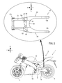
- FIG. 2 is a left side view illustrating the schematic configuration of the vehicle and a top view illustrating the schematic configuration of the rear arm.
- FIG. 3 is a perspective view showing a schematic configuration of the main frame.
- FIG. 4 is a perspective view showing a schematic configuration of the rear arm.
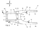
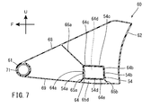
- FIG. 5 is a top view of the rear arm. 6 is a cross-sectional view taken along line VI-VI in FIG. 7 is a cross-sectional view taken along line VII-VII in FIG.
- FIG. 8 is a top view of the rear arm disassembled into a left arm portion, a cross portion, and a right arm portion as viewed from above.
- FIG. 1 is a left side view of a vehicle according to Embodiment 1 of the present invention.
- FIG. 2 is a left side view illustrating the schematic configuration of the vehicle and a top view illustrating the schematic configuration of the rear arm.
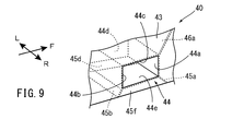
- FIG. 9 is an enlarged perspective view showing the left arm recess in the left arm portion.
- FIG. 10 is an enlarged perspective view of the right arm recess in the right arm portion.
- FIG. 11 is a perspective view illustrating a state in which the rear arm is disassembled into a left arm portion, a cross portion, and a right arm portion.
- FIG. 12 is a left side view of the vehicle schematically showing a case where the rear wheel is displaced upward.
- FIG. 13 is a diagram schematically showing the force that the rear arm receives from the rear suspension when the rear wheel is displaced upward.
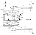
- FIG. 14 is a view corresponding to FIG. 8 of the rear arm of the vehicle according to the second embodiment.
- 15 is a cross-sectional view taken along line XV-XV in FIG.
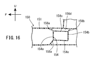
- FIG. 16 is a cross-sectional view taken along line XVI-XVI in FIG.
- FIG. 17 is an enlarged perspective view showing the cross left concave portion in the cross portion.
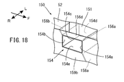
- FIG. 18 is an enlarged perspective view showing the cross right concave portion in the cross portion.
- FIG. 19 is a view corresponding to FIG. 8 of the rear arm of the vehicle according to the third embodiment.
- FIG. 20 is a view corresponding to FIG. 8 of the rear arm of the vehicle according to the fourth embodiment.
- the arrow F in the figure indicates the forward direction of the vehicle.
- An arrow U in the figure indicates the upward direction of the vehicle.
- An arrow R in the figure indicates the right direction of the vehicle.
- An arrow L in the figure indicates the left direction of the vehicle.
- the front-rear and left-right directions mean front-rear and left-right directions when viewed from the occupant driving the vehicle.
- FIG. 1 is a side view illustrating the outline of the overall configuration of the vehicle 1 according to the first embodiment.
- the main frame 12, the rear arm 14, and the rear suspension 9 are indicated by solid lines, and the others are indicated by broken lines.
- FIG. 2 is a left side view illustrating a schematic configuration of the vehicle 1 and a top view of the rear arm 14 as viewed from above. With reference to FIG.1 and FIG.2, schematic structure of the vehicle 1 is demonstrated.
- the vehicle 1 is a motorcycle, for example, and includes a vehicle body 2, a front wheel 3, and a rear wheel 4 (wheels).
- the vehicle body 2 includes a handle 6, a seat 7, a rear suspension 9 (suspension), a vehicle body frame 10, and a rear arm 14 (swing arm).
- the body frame 10 supports components such as the handle 6, the seat 7, the rear suspension 9, the rear arm 14, and a power unit (not shown).
- the rear arm 14 is supported by the vehicle body frame 10 via the rear suspension 9 while rotatably supporting the rear wheel 4 at the rear end portion. The detailed configuration of the rear arm 14 will be described later.
- the vehicle body frame 10 has a head pipe 11, a main frame 12, and a rear frame (not shown).
- the head pipe 11 is located at the front of the vehicle 1 and rotatably supports a steering shaft (not shown) connected to the handle 6.
- the head pipe 11 is connected to the front end portion of the main frame 12.
- the main frame 12 is connected to the head pipe 11 so as to extend from the head pipe 11 toward the rear of the vehicle.
- the main frame 12 has a left main frame 20 and a right main frame 30.
- the left main frame 20 and the right main frame 30 are each formed in a plate shape extending in the vehicle front-rear direction.
- the left main frame 20 has a left main frame front portion 21 extending rearward and downward from the head pipe 11 and a left main frame 20 extending downward from a rear end portion of the left main frame front portion 21.
- the right main frame 30 includes a right main frame front portion 31 extending rearward and downward from the head pipe 11 and a right main frame rear portion 32 extending downward from the rear end portion of the right main frame front portion 31.
- the front end portions of the left main frame 20 and the right main frame 30 are connected to the head pipe 11, respectively. That is, the front end portion of the left main frame front portion 21 in the left main frame 20 and the front end portion of the right main frame front portion 31 in the right main frame 30 are connected.
- the main frame 12 has a front connection portion 12a in which the front end portion of the left main frame front portion 21 and the front end portion of the right main frame front portion 31 are connected.
- the rear end portion of the left main frame rear portion 22 in the left main frame 20 and the rear end portion of the right main frame rear portion 32 in the right main frame 30 are connected by a cross member 17 extending in the left-right direction.
- the main frame 12 has a rear connection portion 12b in which a rear end portion of the left main frame rear portion 22 and a rear end portion of the right main frame rear portion 32 are connected.
- the main frame 12 has an intermediate portion 12c between the front connection portion 12a and the rear connection portion 12b in the front-rear direction.
- the left main frame 20 and the right main frame 30 are not connected linearly and integrally when viewed from the front-rear direction. That is, the left main frame 20 and the right main frame 30 are not connected linearly and integrally when viewed from the front-rear direction, except for the front connection portion 12a and the rear connection portion 12b.
- the main frame 12 has the accommodating space 12d between the left main frame 20 and the right main frame 30 and in the center portion in the front-rear direction.
- a tank, an air cleaner, and the like (not shown) are disposed in the housing space 12d.
- the left main frame 20 and the right main frame 30 are not connected linearly and integrally when viewed from the front-rear direction in portions other than the front connection portion 12a and the rear connection portion 12b.
- the placement of parts is less likely to be restricted. Therefore, the degree of freedom in designing the arrangement of components with respect to the main frame 12 can be improved.
- the rear arm 14 is rotatably supported at the rear part of the left main frame 20 and the right main frame 30. That is, the left main frame rear portion 22 is located to the left of the front end portion of the rear arm 14 and rotatably supports the front end portion of the rear arm 14.
- the right main frame rear portion 32 is located to the right of the front end portion of the rear arm 14 and rotatably supports the front end portion of the rear arm 14.
- the main frame 12 includes a left suspension support portion 25 that extends rearward and upward from the left main frame 20 and a right suspension support portion 35 that extends rearward and upward from the right main frame 30.
- the front end portion of the left suspension support portion 25 is fixed to the left main frame 20.
- the left suspension support portion 25 extends rearward and upward from a connection portion between the left main frame front portion 21 and the left main frame rear portion 22.
- the front end of the right suspension support portion 35 is fixed to the right main frame 30.
- the right suspension support portion 35 extends rearward and upward from a connection portion between the right main frame front portion 31 and the right main frame rear portion 32.
- the left suspension support portion 25 and the right suspension support portion 35 extend rearward and upward so that their rear end portions approach each other in the left-right direction.
- the rear end portion of the left suspension support portion 25 and the rear end portion of the right suspension support portion 35 are connected in the left-right direction.
- the main frame 12 has a suspension mounting portion 16 protruding rearward at the rear end portion where the left suspension support portion 25 and the right suspension support portion 35 are connected.
- the suspension attachment portion 16 supports the front end portion of the rear suspension 9.
- the suspension mounting portion 16 includes a pair of cylindrical portions 16a arranged at a predetermined interval in the left-right direction.
- the pair of cylindrical portions 16a are arranged so that the cylinder axis direction extends in the left-right direction.
- a front end portion of the rear suspension 9 is rotatably connected to the pair of cylindrical portions 16a.
- the rear end of the rear suspension 9 is supported by a rear arm 14. That is, the rear suspension 9 is supported by the suspension mounting portion 16 and the rear arm 14 of the main frame 12. Thereby, when a load in the vertical direction is input to the rear arm 14 that supports the rear wheel 4, the load is input to the suspension mounting portion 16 of the main frame 12 via the rear suspension 9.
- the main frame 12 also supports a power unit and a rear frame (not shown).
- the power unit is attached to the lower part of the left main frame 20 and the right main frame 30 of the main frame 12.
- the rear frame is attached to the left main frame 20 and the right main frame 30 of the main frame 12 behind the left suspension support portion 25 and the right suspension support portion 35.
- reference numerals 20a and 30a are rear frame mounting portions provided on the left main frame 20 and the right main frame 30, respectively.
- Reference numerals 20b and 30b denote attachment portions of the rear arm 14 provided on the left main frame 20 and the right main frame 30, respectively.
- reference numerals 20c and 30c denote power unit mounting portions provided on the left main frame 20 and the right main frame 30, respectively.
- the seat 7 is supported by a rear frame. As shown in FIG. 1, the seat 7 is provided in the center portion of the vehicle 1 in the front-rear direction. As a result, the occupant grips the handle 6 located at the front portion of the vehicle 1 while straddling the seat 7.
- the left main frame 20, the right main frame 30, and the rear frame may be made of a metal material, or may be made of a fiber reinforced resin in which a resin is reinforced with a fiber such as carbon fiber.
- the left main frame 20, the right main frame 30, and the rear frame may be made of any material as long as the material can function as a vehicle body frame of the vehicle 1.
- FIG. 4 is a perspective view showing a schematic configuration of the rear arm 14.
- FIG. 5 is a top view showing a schematic configuration of the rear arm 14.
- 6 is a cross-sectional view taken along line VI-VI in FIG. 7 is a cross-sectional view taken along line VII-VII in FIG.
- the front end portion of the rear arm 14 is rotatably supported by the main frame 12.
- the rear end portion of the rear arm 14 supports the rear wheel 4 in a rotatable manner.
- the rear arm 14 rotates in the vertical direction about the front end portion rotatably supported by the main frame 12.
- the rear arm 14 is also connected to the main frame 12 by the rear suspension 9.
- the rear arm 14 is located at the front end and is connected to the main frame 12 so as to be rotatable, and the rear arm 14 is located at the rear end and rotates the rear wheel 4. It has a pair of rear wheel support portions 14b (wheel support portions) to be supported and a pair of suspension connection portions 14c to which the rear suspension 9 is connected.
- the frame connecting portion 14a has a pivot shaft 71 described later.
- the pivot shaft 71 is rotatably supported by the attachment portions 20b and 30b of the main frame 12.
- the rear wheel support portion 14b is located on the left and right sides with respect to the rear wheel 4, and supports the rear wheel 4 so as to be rotatable.
- the rear arm 14 has a shape in which a central portion in the front-rear direction protrudes upward. Thereby, the rigidity of the rear arm 14 in the vertical direction can be improved. Therefore, as will be described later, the rear wheel 4 can be supported by the rear arm 14 when a vertical displacement is input to the rear wheel 4.
- the rear part of the rear arm 14 is divided into two on the left and right.
- the rear wheel support portions 14b are respectively provided at the rear end portions of the rear portion divided into the left and right parts in this way. That is, the rear portion of the rear arm 14 is located on the left and right sides of the rear wheel 4.
- the rear arm 14 has three members arranged in the left-right direction. Specifically, the rear arm 14 has a left arm part 40, a cross part 50, and a right arm part 60.
- the left arm portion 40 constitutes the left portion of the rear arm 14.
- the right arm unit 60 constitutes the right part of the rear arm 14.
- the cross part 50 is located between the left arm part 40 and the right arm part 60 in the left-right direction.
- the left arm part 40, the cross part 50, and the right arm part 60 are connected to each other by, for example, an adhesive or a resin in a state where they are arranged in the left-right direction. Thereby, the left arm part 40, the cross part 50, and the right arm part 60 are integrated.
- the left arm portion 40 is located on the left side with respect to the rear wheel 4.
- the right arm portion 60 is located on the right side with respect to the rear wheel 4. Accordingly, the rear arm 14 is disposed with respect to the rear wheel 4 such that the rear wheel 4 is positioned between the left arm portion 40 and the right arm portion 60.
- the left arm portion 40, the cross portion 50, and the right arm portion 60 are each reinforced by a fiber sheet in which a resin (for example, epoxy resin, vinyl ester, phenol resin, polyamide, polypropylene, polyphenylene sulfide, etc.) contains carbon fibers. It is made of carbon fiber reinforced resin.
- the said fiber sheet is formed in the sheet form by knitting a fiber. The said fiber sheet is couple
- the fiber sheets are laminated in the thickness direction of each surface constituting the left arm part 40, the cross part 50, and the right arm part 60, respectively.
- strength of the direction along these surfaces is higher than the intensity
- rear wheel support portion 14b, the pivot shaft 71 and the connection fitting 72 described later are made of, for example, a metal material, resin, or the like.
- the left arm portion 40 has an outer dimension in the vertical direction larger than an outer dimension in the left-right direction when viewed in the left-right cross section.
- the left arm portion 40 has a shape in which a central portion in the front-rear direction protrudes upward. Thereby, the rigidity of the rear arm 14 in the vertical direction can be improved. Therefore, as will be described later, the rear arm 14 has higher strength with respect to the force input downward from the rear suspension 9 to the rear arm 14.
- the left arm portion 40 has a left arm left side surface portion 42 that constitutes the left surface and extends in the front-rear direction, and a left arm right side surface portion 43 that constitutes the right surface and extends in the front-rear direction.
- the left arm left side surface portion 42 and the left arm right side surface portion 43 have a shape in which a central portion in the front-rear direction protrudes upward when viewed from the left-right direction. Note that the left arm left side surface portion 42 and the left arm right side surface portion 43 are connected at the upper end portions by the left arm upper surface portion 48 and at the lower end portions by the left arm lower surface portion 49.
- the left arm portion 40 extends from the frame connection portion 14a to the rear wheel support portion 14b in the front-rear direction. That is, the front end portion of the left arm portion 40 is connected to the pivot shaft 71, and the rear end portion of the left arm portion 40 supports the rear wheel support portion 14b. Specifically, the left arm portion 40 has a cylindrical cylindrical portion 41 into which a pivot shaft 71 can be inserted at the front end portion. The left arm portion 40 has a support portion insertion recess 40a at the rear end portion where the rear wheel support portion 14b can be disposed. The left arm portion 40 has an opening 40b through which a chain (not shown) that transmits driving force from a power unit (not shown) to the rear wheel 4 passes.
- the left arm portion 40 has a left arm recess 44 in the left arm right side surface portion 43 in front of the central portion in the front-rear direction of the rear arm 14.
- the left arm recess 44 is recessed in the left arm portion 40 from the left arm right side surface portion 43 toward the left arm left side surface portion 42.
- the left arm recess 44 has a trapezoidal shape when viewed from above.
- the left arm recessed part 44 is rectangular shape seeing from the left-right direction.
- a later-described cross left convex portion 53 of the cross portion 50 is located in the left arm concave portion 44. A detailed configuration of the left arm recess 44 will be described later.
- the right arm portion 60 has an outer dimension in the vertical direction larger than an outer dimension in the left-right direction when viewed in the left-right direction cross section. Further, the right arm portion 60 has a shape in which a central portion protrudes upward in the front-rear direction. Thereby, the rigidity of the rear arm 14 in the vertical direction can be improved. Therefore, as will be described later, the rear arm 14 has higher strength with respect to the force input downward from the rear suspension 9 to the rear arm 14.
- the right arm portion 60 includes a right arm left side surface portion 62 that constitutes the left surface and extends in the front-rear direction, and a right arm right side surface portion 63 that constitutes the right surface and extends in the front-rear direction.
- the right arm left side surface portion 62 and the right arm right side surface portion 63 have a shape in which a central portion in the front-rear direction protrudes upward when viewed from the left-right direction.
- the right arm left side surface portion 62 and the right arm right side surface portion 63 have upper ends connected to each other by a right arm upper surface portion 68 and lower ends connected to each other by a right arm lower surface portion 69.
- the right arm portion 60 extends from the frame connection portion 14a to the rear wheel support portion 14b in the front-rear direction. That is, the front end portion of the right arm portion 60 is connected to the pivot shaft 71, and the rear end portion of the right arm portion 60 supports the rear wheel support portion 14b. Specifically, the right arm portion 60 has a cylindrical cylindrical portion 61 into which a pivot shaft 71 can be inserted at the front end portion. The right arm portion 60 has a support portion insertion recess 60a at the rear end portion where the rear wheel support portion 14b can be disposed.
- the right arm portion 60 has a right arm recess 64 in the right arm left side surface portion 62 in front of the central portion in the front-rear direction of the rear arm 14.
- the right arm recess 64 is recessed in the right arm portion 60 from the right arm left side portion 62 toward the right arm right side portion 63.
- the right arm recess 64 has a trapezoidal shape when viewed from above.
- the right arm recessed part 64 is rectangular shape seeing from the left-right direction.
- a later-described cross right convex portion 54 of the cross portion 50 is located in the right arm concave portion 64. The detailed configuration of the right arm recess 64 will be described later.
- left arm portion 40 and the right arm portion 60 have the same outer shape when viewed from the left-right direction.
- the cross portion 50 extends from the frame connecting portion 14a to the center portion of the rear arm 14 in the front-rear direction.
- the cross portion 50 has a front end portion connected to the frame connection portion 14a, a flat portion 51 extending to the center portion of the rear arm 14 in the front-rear direction, and a vertical wall portion 52 extending upward from the rear end portion of the flat portion 51.
- the plane part 51 and the vertical wall part 52 are integrally formed.
- the flat part 51 has two plate-like members arranged in parallel in the vertical direction, although not particularly shown.
- the flat part 51 has a front end connected to the frame connecting part 14 a and both ends in the left-right direction connected to the left arm part 40 and the right arm part 60.
- the vertical wall portion 52 is connected to the rear end portion of the flat surface portion 51, and both left and right end portions are connected to the left arm portion 40 and the right arm portion 60.
- the vertical wall portion 52 extends from the flat surface portion 51 to the same height as the center portion in the front-rear direction of the left arm portion 40 and the right arm portion 60.
- a pair of left and right suspension connection portions 14c are formed at a connection portion between the rear end portion of the flat portion 51 and the lower front portion of the vertical wall portion 52. That is, the suspension connection portion 14 c protrudes upward with respect to the flat portion 51 and protrudes forward with respect to the vertical wall portion 52.
- the suspension connection portion 14c has a cylindrical connection fitting 72 to which the rear end portion of the rear suspension 9 is connected.
- a pivot shaft 71 is connected to the front end portion of the cross portion 50.
- the pivot shaft 71 is a metal cylindrical member.
- the pivot shaft 71 is connected to the front end portion of the cross portion 50 so that the axial direction is the left-right direction.
- the pivot shaft 71 constitutes a part of the frame connecting portion 14a.
- the frame connecting portion 14 a includes a pivot shaft 71, a cylindrical portion 41 of the left arm portion 40, and a cylindrical portion 61 of the right arm portion 60.
- the cylindrical portions 41 and 61 are connected to the pivot shaft 71 by, for example, resin or adhesive.
- the cylindrical portion 41 and the pivot shaft 71 constitute a rotating left support portion 14d.
- the cylindrical portion 61 and the pivot shaft 71 constitute a rotating right support portion 14e.
- the cross portion 50 has a cross left convex portion 53 and a cross right convex portion 54 that protrude in the left-right direction in front of the center portion in the front-rear direction of the rear arm 14.
- the cross left convex portion 53 extends leftward from the flat portion 51.
- the cross right convex portion 54 extends rightward from the flat portion 51.
- the cross left convex portion 53 and the cross right convex portion 54 are trapezoidal when viewed from above.
- the cross left convex portion 53 and the cross right convex portion 54 are rectangular when viewed from the left-right direction.
- the cross left convex portion 53 is located in the left arm concave portion 44 of the left arm portion 40 in the rear arm 14.
- the cross right convex portion 54 is located in the right arm concave portion 64 of the right arm portion 60 in the rear arm 14. Detailed configurations of the cross left convex portion 53 and the cross right convex portion 54 will be described later.
- the left arm portion 40, the cross portion 50, and the right arm portion 60 having the above-described configuration are bonded and fixed to each other in a state where they are arranged in the left-right direction, as will be described later. That is, the cross left convex portion 53 of the cross portion 50 is inserted into the left arm concave portion 44 of the left arm portion 40, and the cross right convex portion 54 of the cross portion 50 is inserted into the right arm concave portion 64 of the right arm portion 60. In this state, the left arm part 40, the cross part 50, and the right arm part 60 are bonded and fixed. Note that both end portions in the axial direction of the pivot shaft 71 connected to the front end portion of the cross portion 50 are inserted into the cylindrical portions 41 and 61 of the left arm portion 40 and the right arm portion 60, respectively.
- FIG. 8 is a top view showing a state in which the rear arm 14 is disassembled into the left arm part 40, the cross part 50 and the right arm part 60.
- FIG. 11 is a perspective view showing a state in which the rear arm 14 is disassembled into a left arm part 40, a cross part 50 and a right arm part 60.
- the left arm portion 40 has a left arm recess 44 in the left arm right side surface portion 43.
- the left arm recess 44 includes a left arm recess front surface portion 44a, a left arm recess rear surface portion 44b, a left arm recess upper surface portion 44c, a left arm recess left surface portion 44d, and a left arm recess lower surface portion 44e.
- the left arm recess 44 is surrounded by the left arm recess front surface portion 44a, the left arm recess rear surface portion 44b, the left arm recess upper surface portion 44c, the left arm recess left surface portion 44d, and the left arm recess lower surface portion 44e. Have space.
- the left arm recess 44 is made of a carbon fiber reinforced resin in which a resin (for example, epoxy resin, vinyl ester, phenol resin, polyamide, polypropylene, polyphenylene sulfide, etc.) is reinforced by a fiber sheet containing carbon fibers. That is, the left arm recess front surface portion 44a, the left arm recess rear surface portion 44b, the left arm recess upper surface portion 44c, the left arm recess left surface portion 44d, and the left arm recess lower surface portion 44e are each reinforced with a fiber sheet in which the resin contains carbon fibers. Made of carbon fiber reinforced resin.
- a resin for example, epoxy resin, vinyl ester, phenol resin, polyamide, polypropylene, polyphenylene sulfide, etc.
- the said fiber sheet is formed in the sheet form by knitting a fiber.
- a plurality of the fiber sheets are bonded with resin in a state where a plurality of the fiber sheets are stacked in the thickness direction of each surface.
- the left arm recess front surface portion 44 a is a surface located at the front portion of the left arm recess 44.
- the left arm recess front surface portion 44a extends in the left-right direction from the left arm right side surface portion 43 to the left arm recess left surface portion 44d positioned inward of the left arm portion 40 relative to the left arm left side surface portion 42.
- the left arm recess rear surface portion 44 b is a surface located at the rear portion of the left arm recess 44.
- the left arm recess rear surface portion 44b is also located in the left arm recess left surface portion located inward of the left arm portion 40 from the left arm right side surface portion 43 in the left-right direction. It extends to 44d.
- the left arm concave front surface 44a and the left arm concave rear surface 44b are arranged in parallel in the front-rear direction. That is, the left arm recess front surface portion 44a and the left arm recess rear surface portion 44b are disposed to face each other in the front-rear direction.
- the left arm recess rear surface portion 44b is longer in the left-right direction than the left arm recess front surface portion 44a.
- the left arm recess upper surface portion 44 c is a surface located at the upper portion of the left arm recess 44.
- the left arm recess upper surface portion 44c also extends in the left-right direction from the left arm right side surface portion 43 to the left arm recess left surface portion 44d positioned inward of the left arm portion 40 with respect to the left arm left side surface portion 42.
- the left arm recess upper surface portion 44c has a trapezoidal shape when viewed from above.
- the left arm recess lower surface portion 44 e is a surface located at the lower portion of the left arm recess 44.
- the left arm recess lower surface portion 44e also extends in the left-right direction from the left arm right side surface portion 43 to the left arm recess left surface portion 44d positioned inward of the left arm portion 40 relative to the left arm left side surface portion 42.
- the left arm recess upper surface portion 44c and the left arm recess lower surface portion 44e are arranged in parallel in the vertical direction. That is, the left arm recess upper surface portion 44c and the left arm recess lower surface portion 44e are arranged to face each other in the vertical direction.
- the left arm recess lower surface portion 44e has a trapezoidal shape when viewed from above.
- the left arm recess left surface portion 44 d is a surface located at the left portion of the left arm recess 44.
- the left arm recess left surface portion 44 d is positioned inward of the left arm portion 40 with respect to the left arm left surface portion 42 so as to follow the left arm left surface portion 42.
- the left arm recess left surface 44d has a rectangular shape when viewed from the left-right direction.
- the left arm left side surface portion 42 constituting the left arm concave portion left surface portion 44d is located to the left of the left arm concave portion 44. As a result, the left arm recess 44 is not exposed to the left of the left arm 40. Therefore, it is possible to prevent the appearance of the rear arm 14 from being damaged when the rear arm 14 is viewed from the left.
- the left arm recess front surface portion 44a, the left arm recess rear surface portion 44b, the left arm recess upper surface portion 44c, the left arm recess left surface portion 44d The cross left convex portion 53 of the cross portion 50 is located in the left arm concave portion 44 constituted by the arm concave portion lower surface portion 44e. That is, the lower load of the left arm concave portion 44e receives a downward load of the cross portion 50.
- a left arm load receiving surface is configured by the left arm recess lower surface portion 44e. Further, as will be described later, a reaction force received by the rear arm 14 from the rear suspension 9 when the rear wheel 4 is displaced upward is input to the left arm recess lower surface 44e.
- the left arm portion 40 has a plurality of surfaces that support the left arm recess lower surface portion 44e.
- the left arm portion 40 includes a left arm recess front lower surface portion 45 a, a left arm recess rear lower surface portion 45 b, and a left arm recess left lower surface portion. 45d and a left arm recess right lower surface portion 45f.
- the left arm recess front lower surface portion 45a, the left arm recess rear lower surface portion 45b, the left arm recess left lower surface portion 45d, and the left arm recess right lower surface portion 45f are left arm load receiving surface support portions.
- the left arm recess left lower surface portion 45 d is a part of the left arm left side surface portion 42
- the left arm recess right lower surface portion 45 f is a part of the left arm right side surface portion 43.
- the left arm recess left lower surface portion 45 d may be provided separately from the left arm left side surface portion 42.
- the left arm recess right lower surface portion 45 f may be provided separately from the left arm right surface portion 43.
- the left arm recess front lower surface portion 45a, the left arm recess rear lower surface portion 45b, the left arm recess left lower surface portion 45d, and the left arm recess right lower surface portion 45f are each made of resin (for example, epoxy resin, vinyl ester, phenol resin, polyamide, polypropylene). , Polyphenylene sulfide, etc.) is composed of a carbon fiber reinforced resin reinforced with a fiber sheet containing carbon fibers.
- the said fiber sheet is formed in the sheet form by knitting a fiber.
- a plurality of the fiber sheets are bonded with resin in a state where a plurality of the fiber sheets are stacked in the thickness direction of each surface.
- the left arm recess front lower surface portion 45 a is located below and in front of the left arm recess 44.
- the left arm recess rear lower surface portion 45 b is located below and behind the left arm recess 44.
- the left arm recess left lower surface portion 45 d is located below the left arm recess 44 and on the left surface of the left arm portion 40.
- the left arm recess right lower surface portion 45 f is located below the left arm recess 44 and on the right surface of the left arm portion 40.
- the left arm recess front lower surface portion 45a and the left arm recess rear lower surface portion 45b are disposed to face each other in the front-rear direction.
- the left arm recess left lower surface portion 45d and the left arm recess right lower surface portion 45f are disposed to face each other in the left-right direction.
- the left arm recess front lower surface portion 45a, the left arm recess rear lower surface portion 45b, the left arm recess left lower surface portion 45d and the left arm recess right lower surface portion 45f are connected to the left arm recess lower surface portion 44e and The left arm lower surface part 49 is also connected.
- the left arm recess front lower surface portion 45a, the left arm recess rear lower surface portion 45b, the left arm recess left lower surface portion 45d, and the left arm recess right lower surface portion 45f are connected to the peripheral edge of the left arm recess lower surface portion 44e.
- the left arm recess front lower surface portion 45a extends forward and downward from a connection portion between the left arm recess lower surface portion 44e and the left arm recess front surface portion 44a when viewed from the left-right direction.
- the left arm recess rear lower surface portion 45b extends rearward and downward from a connection portion between the left arm recess lower surface portion 44e and the left arm recess rear surface portion 44b when viewed from the left-right direction.
- the left arm recess lower surface 44e is supported from below by the four surfaces of the left arm recess front lower surface 45a, the left arm recess rear lower surface 45b, the left arm recess left lower surface 45d and the left arm recess right lower surface 45f. By doing so, a downward load can be more reliably received by the left arm recess lower surface portion 44e.
- one of the left arm portions 40 is connected to a connecting portion between the left arm recessed portion front surface portion 44a and the left arm recessed portion upper surface portion 44c of the left arm recessed portion 44, and the other is forward of the connecting portion and A left arm recess front upper surface portion 46a that extends upward and is connected to the left arm upper surface portion 48 of the left arm portion 40 (the outer surface of the left arm portion 40).
- strength of the left arm recessed part front part 44a and the left arm recessed part upper surface part 44c can be improved.
- the front upper surface portion 46a of the left arm recess is made of a carbon fiber reinforced resin in which a resin (for example, epoxy resin, vinyl ester, phenol resin, polyamide, polypropylene, polyphenylene sulfide, etc.) is reinforced by a fiber sheet containing carbon fibers.
- a resin for example, epoxy resin, vinyl ester, phenol resin, polyamide, polypropylene, polyphenylene sulfide, etc.
- the said fiber sheet is formed in the sheet form by knitting a fiber.
- a plurality of the fiber sheets are bonded together by a resin in a state where a plurality of the fiber sheets are stacked in the thickness direction of the front upper surface portion 46a of the left arm recess.
- the cross part 50 has a trapezoidal cross left convex part 53 in a top view protruding leftward from the flat part 51.
- the cross left convex portion 53 has a rectangular tube shape when viewed from the left-right direction. That is, the cross left convex portion 53 has a closed cross-sectional shape when viewed in the cross-section in the front-rear direction.
- the cross left convex portion 53 includes a cross left convex portion front surface portion 53a, a cross left convex portion rear surface portion 53b, a cross left convex portion upper surface portion 53c, and a cross left convex portion lower surface portion 53d.
- the cross left convex portion front surface portion 53a, the cross left convex portion rear surface portion 53b, the cross left convex portion upper surface portion 53c, and the cross left convex portion lower surface portion 53d constitute each side surface of the square tube.
- the cross left convex portion 53 is made of a carbon fiber reinforced resin in which a resin (for example, epoxy resin, vinyl ester, phenol resin, polyamide, polypropylene, polyphenylene sulfide, etc.) is reinforced by a fiber sheet containing carbon fibers. That is, the cross left convex portion front surface portion 53a, the cross left convex portion rear surface portion 53b, the cross left convex portion upper surface portion 53c, and the cross left convex portion lower surface portion 53d are each a carbon whose resin is reinforced by a fiber sheet containing carbon fibers. It is composed of fiber reinforced resin.
- a resin for example, epoxy resin, vinyl ester, phenol resin, polyamide, polypropylene, polyphenylene sulfide, etc.
- the said fiber sheet is formed in the sheet form by knitting a fiber.
- a plurality of the fiber sheets are bonded with resin in a state where a plurality of the fiber sheets are stacked in the thickness direction of each surface.
- the cross left convex portion front surface portion 53 a is located at the front portion of the cross left convex portion 53.
- the cross left convex portion rear surface portion 53 b is located at the rear portion of the cross left convex portion 53.
- the cross left convex portion upper surface portion 53 c is positioned above the cross left convex portion 53.
- the cross left convex portion lower surface portion 53 d is located below the cross left convex portion 53.
- the cross left convex portion front surface portion 53a and the cross left convex portion rear surface portion 53b are arranged in parallel in the front-rear direction.
- the cross left convex portion front surface portion 53a and the cross left convex portion rear surface portion 53b have a rectangular shape when viewed from the front-rear direction.
- the cross left convex part rear surface part 53b protrudes leftward from the cross left convex part front part 53a.
- the cross left convex portion upper surface portion 53c and the cross left convex portion lower surface portion 53d are arranged in parallel in the vertical direction.
- the cross left convex portion upper surface portion 53c and the cross left convex portion lower surface portion 53d are trapezoidal in top view and have the same size.
- the cross left convex portion 53 has a trapezoidal rectangular tube shape in a top view.
- the cross left convex portion lower surface portion 53 d of the cross left convex portion 53 contacts the left arm concave portion lower surface portion 44 e of the left arm concave portion 44. That is, the cross left convex portion 53 is supported by the left arm concave portion lower surface portion 44 e of the left arm concave portion 44.
- the right arm portion 60 includes a right arm recess 64 in the right arm left side surface portion 62.
- the right arm recess 64 includes a right arm recess front surface portion 64a, a right arm recess rear surface portion 64b, a right arm recess upper surface portion 64c, a right arm recess right surface portion 64d, and a right arm recess lower surface portion 64e.
- the right arm recess 64 is surrounded by the right arm recess front surface portion 64a, the right arm recess rear surface portion 64b, the right arm recess upper surface portion 64c, the right arm recess right surface portion 64d, and the right arm recess lower surface portion 64e. Have space.
- the right arm recess 64 is made of a carbon fiber reinforced resin in which a resin (for example, epoxy resin, vinyl ester, phenol resin, polyamide, polypropylene, polyphenylene sulfide, etc.) is reinforced by a fiber sheet containing carbon fibers. That is, the right arm recess front surface portion 64a, the right arm recess rear surface portion 64b, the right arm recess upper surface portion 64c, the right arm recess right surface portion 64d, and the right arm recess lower surface portion 64e are each reinforced with a fiber sheet in which the resin contains carbon fibers. Made of carbon fiber reinforced resin.
- a resin for example, epoxy resin, vinyl ester, phenol resin, polyamide, polypropylene, polyphenylene sulfide, etc.
- the said fiber sheet is formed in the sheet form by knitting a fiber.
- a plurality of the fiber sheets are bonded with resin in a state where a plurality of the fiber sheets are stacked in the thickness direction of each surface.
- the right arm recess front surface portion 64 a is a surface located at the front portion of the right arm recess 64.
- the right arm recess front surface portion 64a extends in the left-right direction from the right arm left side surface portion 62 to the right arm recess right surface portion 64d positioned inward of the right arm portion 60 with respect to the right arm right side surface portion 63.
- the right arm recess rear surface portion 64 b is a surface located at the rear portion of the right arm recess 64.
- the right arm recess rear surface portion 64b is also located in the right arm recess right surface portion located inward of the right arm portion 60 from the right arm left side surface portion 62 in the left-right direction. It extends to 64d.
- the right arm recess front surface portion 64a and the right arm recess rear surface portion 64b are arranged in parallel in the front-rear direction. That is, the right arm recess front surface portion 64a and the right arm recess rear surface portion 64b are disposed to face each other in the front-rear direction.
- the right arm recess rear surface portion 64b is longer in the left-right direction than the right arm recess front surface portion 64a.
- the right arm recess upper surface portion 64 c is a surface located at the upper portion of the right arm recess 64.
- the right arm recess upper surface portion 64c also extends in the left-right direction from the right arm left side surface portion 62 to the right arm recess right surface portion 64d positioned inward of the right arm portion 60 with respect to the right arm right side surface portion 63.
- the right arm recess upper surface portion 64c is trapezoidal when viewed from above.
- the right arm recess lower surface portion 64 e is a surface located at the lower portion of the right arm recess 64.
- the right arm recess lower surface portion 64e also extends in the left-right direction from the right arm left side surface portion 62 to the right arm recess right surface portion 64d positioned inward of the right arm portion 60 with respect to the right arm right side surface portion 63.
- the right arm recess upper surface portion 64c and the right arm recess lower surface portion 64e are arranged in parallel in the vertical direction. That is, the right arm recess upper surface portion 64c and the right arm recess lower surface portion 64e are arranged to face each other in the vertical direction.
- the right arm recess lower surface portion 64e has a trapezoidal shape when viewed from above.
- the right arm recess right surface portion 64 d is a surface located at the right portion of the right arm recess 64.
- the right arm recessed portion right surface portion 64 d is positioned inward of the right arm portion 60 with respect to the right arm right surface portion 63 so as to follow the right arm right surface portion 63.
- the right arm recess right surface portion 64d has a rectangular shape when viewed from the left-right direction.
- the right arm right side surface portion 63 constituting the right arm recess right surface portion 64d is located to the right of the right arm recess portion 64. As a result, the right arm recess 64 is not exposed to the right of the right arm portion 60. Therefore, it is possible to prevent the appearance of the rear arm 14 from being damaged when the rear arm 14 is viewed from the right.
- the right arm recess front surface portion 64a, the right arm recess rear surface portion 64b, the right arm recess upper surface portion 64c, the right arm recess right surface portion 64d The cross right convex portion 54 of the cross portion 50 is positioned in the right arm concave portion 64 constituted by the arm concave portion lower surface portion 64e. That is, the load in the vertical direction of the cross portion 50 is received by the right arm recess lower surface portion 64e.
- a right arm load receiving surface is configured by the right arm recess lower surface portion 64e.
- the right arm portion 60 since force is input to the right arm recess lower surface portion 64e, the right arm portion 60 has a plurality of surfaces that support the right arm recess lower surface portion 64e. Specifically, as shown in FIGS. 7, 10, and 11, in the present embodiment, the right arm portion 60 includes a right arm recess front lower surface portion 65 a, a right arm recess rear lower surface portion 65 b, and a right arm recess right lower surface. It has a portion 65d and a right arm recess left lower surface portion 65f.
- the right arm recess front lower surface portion 65a, the right arm recess rear lower surface portion 65b, the right arm recess right lower surface portion 65d, and the right arm recess left lower surface portion 65f are right arm load receiving surface support portions.
- the right arm recess right lower surface portion 65d is a part of the right arm right side surface portion 63
- the right arm recess left lower surface portion 65f is a part of the right arm left side surface portion 62.
- the right arm recess right lower surface portion 65 d may be provided separately from the right arm right surface portion 63.
- the right arm recess left lower surface portion 65 f may be provided separately from the right arm left surface portion 62.
- the right arm recess front lower surface portion 65a, the right arm recess rear lower surface portion 65b, the right arm recess right lower surface portion 65d, and the right arm recess left lower surface portion 65f are each made of resin (for example, epoxy resin, vinyl ester, phenol resin, polyamide, polypropylene). , Polyphenylene sulfide, etc.) is composed of a carbon fiber reinforced resin reinforced with a fiber sheet containing carbon fibers.
- the said fiber sheet is formed in the sheet form by knitting a fiber.
- a plurality of the fiber sheets are bonded with resin in a state where a plurality of the fiber sheets are stacked in the thickness direction of each surface.
- the right arm recess front lower surface portion 65a is located below and in front of the right arm recess 64.
- the right arm recess rear lower surface portion 65 b is located below and behind the right arm recess 64.
- the right arm recess right lower surface portion 65 d is located below the right arm recess 64 and on the right surface of the right arm portion 60.
- the right arm recess left lower surface portion 65 f is located below the right arm recess 64 and on the left surface of the right arm portion 60.
- the right arm recess front lower surface portion 65a and the right arm recess rear lower surface portion 65b are disposed to face each other in the front-rear direction.
- the right arm recess right lower surface portion 65d and the right arm recess left lower surface portion 65f are disposed to face each other in the left-right direction.
- the right arm recess front lower surface portion 65a, the right arm recess rear lower surface portion 65b, the right arm recess right lower surface portion 65d and the right arm recess left lower surface portion 65f are connected to the right arm recess lower surface portion 64e and It is also connected to the lower surface portion 69 of the right arm.
- the right arm recess front lower surface portion 65a, the right arm recess rear lower surface portion 65b, the right arm recess right lower surface portion 65d, and the right arm recess left lower surface portion 65f are connected to the peripheral edge of the right arm recess lower surface portion 64e.
- the right arm recess front lower surface portion 65a extends forward and downward from a connection portion between the right arm recess lower surface portion 64e and the right arm recess front surface portion 64a when viewed from the left-right direction.
- the right arm recess rear lower surface portion 65b extends rearward and downward from a connection portion between the right arm recess lower surface portion 64e and the right arm recess rear surface portion 64b when viewed from the left-right direction.
- the lower surface 64e of the right arm recess is supported from below by the four surfaces of the front lower surface 65a of the right arm recess, the lower lower surface 65b of the right arm recess, the right lower surface 65d of the right arm recess and the left lower surface 65f of the right arm recess.
- a downward load can be more reliably received by the right arm recess lower surface portion 64e.
- one of the right arm portions 60 is connected to a connection portion between the right arm recess front surface portion 64a and the right arm recess upper surface portion 64c of the right arm recess 64, and the other is forward and upward from the connection portion.
- Right arm recess front upper surface portion 66a connected to the right arm upper surface portion 68 of the right arm portion 60 (the outer surface of the right arm portion 60).
- the front upper surface portion 66a of the right arm recess is made of a carbon fiber reinforced resin in which a resin (for example, epoxy resin, vinyl ester, phenol resin, polyamide, polypropylene, polyphenylene sulfide, etc.) is reinforced by a fiber sheet containing carbon fibers.
- a resin for example, epoxy resin, vinyl ester, phenol resin, polyamide, polypropylene, polyphenylene sulfide, etc.
- the said fiber sheet is formed in the sheet form by knitting a fiber.
- a plurality of the fiber sheets are bonded together by a resin in a state where a plurality of the fiber sheets are stacked in the thickness direction of the front upper surface portion 66a of the right arm recess.
- the cross part 50 has a trapezoidal cross right convex part 54 in a top view protruding rightward from the flat part 51.
- the cross right convex portion 54 has a rectangular tube shape when viewed from the left-right direction. That is, the cross right convex portion 54 has a closed cross-sectional shape as viewed in the cross-section in the front-rear direction.
- the cross right convex portion 54 includes a cross right convex portion front surface portion 54a, a cross right convex portion rear surface portion 54b, a cross right convex portion upper surface portion 54c, and a cross right convex portion lower surface portion 54d.
- the cross right convex portion front surface portion 54a, the cross right convex portion rear surface portion 54b, the cross right convex portion upper surface portion 54c, and the cross right convex portion lower surface portion 54d constitute each side surface of the square tube.
- the cross right convex portion 54 is made of a carbon fiber reinforced resin in which a resin (for example, epoxy resin, vinyl ester, phenol resin, polyamide, polypropylene, polyphenylene sulfide, etc.) is reinforced by a fiber sheet containing carbon fibers. That is, the cross right convex portion front surface portion 54a, the cross right convex portion rear surface portion 54b, the cross right convex portion upper surface portion 54c, and the cross right convex portion lower surface portion 54d are each made of carbon whose resin is reinforced by a fiber sheet containing carbon fibers. It is composed of fiber reinforced resin.
- a resin for example, epoxy resin, vinyl ester, phenol resin, polyamide, polypropylene, polyphenylene sulfide, etc.
- the said fiber sheet is formed in the sheet form by knitting a fiber.
- a plurality of the fiber sheets are bonded with resin in a state where a plurality of the fiber sheets are stacked in the thickness direction of each surface.
- the cross right convex portion front surface portion 54 a is located at the front portion of the cross right convex portion 54.
- the cross right convex portion rear surface portion 54 b is located at the rear portion of the cross right convex portion 54.
- the cross right convex portion upper surface portion 54 c is located above the cross right convex portion 54.
- the cross right convex portion lower surface portion 54 d is located below the cross right convex portion 54.
- the cross right convex portion front surface portion 54a and the cross right convex portion rear surface portion 54b are arranged in parallel in the front-rear direction.
- the cross right convex portion front surface portion 54a and the cross right convex portion rear surface portion 54b have a rectangular shape when viewed from the front-rear direction.
- the cross right convex portion rear surface portion 54b protrudes to the right from the cross right convex portion front surface portion 54a.
- the cross right convex portion upper surface portion 54c and the cross right convex portion lower surface portion 54d are arranged in parallel in the vertical direction.
- the cross right convex portion upper surface portion 54c and the cross right convex portion lower surface portion 54d are trapezoidal in top view and have the same size.
- the cross right convex portion 54 has a trapezoidal rectangular tube shape in a top view.
- the cross right convex portion lower surface portion 54 d of the cross right convex portion 54 contacts the right arm concave portion lower surface portion 64 e of the right arm concave portion 64. That is, the cross right convex portion 54 is supported by the right arm concave portion lower surface portion 64 e of the right arm concave portion 64.
- FIG. 12 is a left side view of the vehicle 1 schematically showing the case where the rear wheel 4 is displaced upward.
- the state before the rear wheel 4 is displaced is indicated by a one-dot chain line, and the rear wheel 4 after the displacement is indicated by a solid line.
- FIG. 13 is a diagram schematically showing the force that the rear arm 14 receives from the rear suspension 9 when the rear wheel 4 is displaced upward as shown in FIG.
- the cross left convex portion 53 of the cross portion 50 has a left arm concave front surface 44a, a left arm concave rear surface 44b, a left arm concave upper surface 44c, and a left arm concave lower surface 44e.
- the cross right convex portion 54 of the cross portion 50 is in a right arm concave portion 64 having a right arm concave portion front surface portion 64a, a right arm concave portion rear surface portion 64b, a right arm concave portion upper surface portion 64c, and a right arm concave portion lower surface portion 64e. To position.
- the cross left convex portion 53 and the cross right convex portion 54 are inserted into the left arm concave portion 44 and the right arm concave portion 64 respectively surrounded by the four surfaces. Therefore, the cross left convex portion 53 and the cross right convex portion 54 can be more reliably inserted into the left arm concave portion 44 and the right arm concave portion 64. Moreover, with the above configuration, the cross left convex portion 53 is formed by the respective surfaces of the left arm concave portion 44 and the right arm concave portion 64 even when a force is input to the cross portion 50 in either the vertical direction or the horizontal direction. In addition, the force input to the cross right convex portion 54 can be received.
- the cross left convex portion 53 and the cross right convex portion 54 of the cross portion 50 are located in the left arm concave portion 44 of the left arm portion 40 and the right arm concave portion 64 of the right arm portion 60, and the left arm concave portion lower surface portion 44e and It is supported by the right arm recess lower surface portion 64e. Therefore, the downward force input to the cross portion 50 as described above is received by the left arm recess lower surface portion 44e and the right arm recess lower surface portion 64e.
- each surface constituting the left arm portion 40, the cross portion 50, and the right arm portion 60 is made of a carbon fiber reinforced resin in which fiber sheets stacked in the thickness direction are bonded together by a resin. Therefore, the rear arm 14 can be reduced in weight.
- the strength of the rear arm 14 can be secured without increasing the number of laminated fiber sheets in order to secure the strength of the rear arm. Therefore, it is possible to improve the support strength of the cross portion 50 to which the rear suspension 9 is connected in the rear arm 14 while suppressing an increase in the weight of the rear arm 14.
- the left arm recess lower surface 44e is supported by the left arm recess front lower surface 45a, the left arm recess rear lower surface 45b, the left arm recess left lower surface 45d, and the left arm recess right lower surface 45f.
- the right arm recess lower surface portion 64e is supported by the right arm recess front lower surface portion 65a, the right arm recess rear lower surface portion 65b, the right arm recess right lower surface portion 65d, and the right arm recess left lower surface portion 65f.
- Each surface of the left arm part 40, the cross part 50, and the right arm part 60 has higher strength in the direction along the surface than in the thickness direction. Therefore, as described above, the left arm recess lower surface portion 44e and the right arm recess lower surface portion 64e are supported by a plurality of surfaces, thereby supporting the cross left convex portion 53 and the cross right convex portion 54 of the cross portion 50 ( The strength of the connection portion between the left arm portion 40 and the cross portion 50 and the connection portion between the right arm portion 60 and the cross portion 50) can be further improved. Thereby, the strength of the rear arm 14 can be further improved.
- the left arm portion 40 is located on the left side with respect to the rear wheel 4.
- the right arm portion 60 is located on the right side with respect to the rear wheel 4. Therefore, the force input from the rear suspension 9 to the rear arm 14 is input to the connection portion between the left arm portion 40 and the cross portion 50 and the connection portion between the right arm portion 60 and the cross portion 50.
- connection from the left arm 40 and the cross 50 and the connection from the right arm 60 to the cross 50 are connected as described above, so that the input from the rear suspension 9 can be achieved. In contrast, the strength of the rear arm 14 can be ensured.
- FIG. 14 is a top view showing a state in which the rear arm 114 of the vehicle according to the second embodiment is disassembled into a left arm part 140, a cross part 150, and a right arm part 160.
- 15 is a cross-sectional view taken along line XV-XV in FIG. 16 is a cross-sectional view taken along line XVI-XVI in FIG.
- connection structure of the left arm part 140, the cross part 150, and the right arm part 160 is different from that of the first embodiment.
- symbol is attached
- the left arm portion 140 has a left arm convex portion 144 protruding rightward on the left arm right side surface portion 43.
- the right arm portion 160 has a right arm convex portion 164 protruding leftward on the right arm left side surface portion 62.
- the cross portion 150 includes a left side surface portion 159 a positioned at the left end portion of the flat surface portion 151 and a right side surface portion 159 b positioned at the right end portion of the flat surface portion 151.
- the cross portion 150 includes a cross left concave portion 153 located on the left side surface portion 159a and into which the left arm convex portion 144 can be inserted, and a cross right concave portion 154 located on the right side surface portion 159b and into which the right arm convex portion 164 can be inserted. .
- the left arm convex portion 144 is provided in the left arm portion 140 in front of the center portion in the front-rear direction.
- the right arm convex portion 164 is provided in front of the center portion in the front-rear direction in the right arm portion 160.
- the cross left concave portion 153 and the cross right concave portion 154 are provided in the rear arm 114 in front of the center portion in the front-rear direction.
- the left arm convex portion 144 has a rectangular tube shape with a rectangular cross section when viewed from the left-right direction.
- the left arm convex portion 144 has a rectangular shape when viewed from above.
- the left arm convex portion 144 includes a left arm convex portion front surface portion 144a, a left arm convex portion rear surface portion 144b, a left arm convex portion upper surface portion 144c, and a left arm convex portion lower surface portion 144d.
- the left arm convex portion 144 is made of a carbon fiber reinforced resin in which a resin (for example, epoxy resin, vinyl ester, phenol resin, polyamide, polypropylene, polyphenylene sulfide, etc.) is reinforced by a fiber sheet containing carbon fibers. That is, the left arm convex portion front surface portion 144a, the left arm convex portion rear surface portion 144b, the left arm convex portion upper surface portion 144c, and the left arm convex portion lower surface portion 144d are each made of carbon whose resin is reinforced by a fiber sheet containing carbon fibers. It is composed of fiber reinforced resin.
- a resin for example, epoxy resin, vinyl ester, phenol resin, polyamide, polypropylene, polyphenylene sulfide, etc.
- the said fiber sheet is formed in the sheet form by knitting a fiber.
- a plurality of the fiber sheets are bonded with resin in a state where a plurality of the fiber sheets are stacked in the thickness direction of each surface.
- Left arm convex part front part 144a is a surface located in the front part of left arm convex part 144.
- the left arm convex portion rear surface portion 144 b is a surface located at the rear portion of the left arm convex portion 144.
- the left arm convex portion upper surface portion 144 c is a surface located on the upper portion of the left arm convex portion 144.
- the left arm convex portion lower surface portion 144d is a surface located below the left arm convex portion 144.
- the right arm convex portion 164 has a rectangular tube shape with a rectangular cross section when viewed from the left-right direction.
- the right arm convex portion 164 has a rectangular shape in a top view.
- the right arm convex portion 164 includes a right arm convex portion front surface portion 164a, a right arm convex portion rear surface portion 164b, a right arm convex portion upper surface portion 164c, and a right arm convex portion lower surface portion 164d.
- the right arm convex portion 164 is made of a carbon fiber reinforced resin in which a resin (for example, epoxy resin, vinyl ester, phenol resin, polyamide, polypropylene, polyphenylene sulfide, etc.) is reinforced by a fiber sheet containing carbon fibers. That is, the front surface portion 164a of the right arm convex portion, the rear surface portion 164b of the right arm convex portion, the upper surface portion 164c of the right arm convex portion and the lower surface portion 164d of the right arm convex portion are each made of carbon whose resin is reinforced by a fiber sheet containing carbon fibers. It is composed of fiber reinforced resin.
- a resin for example, epoxy resin, vinyl ester, phenol resin, polyamide, polypropylene, polyphenylene sulfide, etc.
- the said fiber sheet is formed in the sheet form by knitting a fiber.
- a plurality of the fiber sheets are bonded with resin in a state where a plurality of the fiber sheets are stacked in the thickness direction of each surface.
- the right arm convex portion front portion 164a is located in front of the right arm convex portion 164.
- the right arm convex portion rear surface portion 164b is located at the rear portion of the right arm convex portion 164.
- the right arm convex portion upper surface portion 164 c is located on the upper side of the right arm convex portion 164.
- the right arm convex portion lower surface portion 164d is located below the right arm convex portion 164.
- the cross left recessed portion 153 is recessed from the left side surface portion 159a toward the inside of the flat surface portion 151. As shown in FIG. 14, the cross left recessed part 153 has a rectangular shape when viewed from above. As shown in FIG. 15, the cross left recessed part 153 has a rectangular shape when viewed from the left-right direction.
- the cross left recessed portion 153 includes a cross left recessed portion front surface portion 153a, a cross left recessed portion rear surface portion 153b, a cross left recessed portion upper surface portion 153c, a cross left recessed portion right surface portion 153d, and a cross left recessed portion lower surface portion 153e.
- the cross left recess 153 is made of a carbon fiber reinforced resin in which a resin (for example, epoxy resin, vinyl ester, phenol resin, polyamide, polypropylene, polyphenylene sulfide, etc.) is reinforced by a fiber sheet containing carbon fibers. That is, the cross left concave front surface portion 153a, the cross left concave rear surface portion 153b, the cross left concave upper surface portion 153c, the cross left concave right surface portion 153d, and the cross left concave lower surface portion 153e are each reinforced with a fiber sheet in which the resin contains carbon fibers. Made of carbon fiber reinforced resin.
- a resin for example, epoxy resin, vinyl ester, phenol resin, polyamide, polypropylene, polyphenylene sulfide, etc.
- the said fiber sheet is formed in the sheet form by knitting a fiber.
- a plurality of the fiber sheets are bonded with resin in a state where a plurality of the fiber sheets are stacked in the thickness direction of each surface.
- the cross left recess front surface portion 153 a is a surface located at the front portion of the cross left recess 153.
- the cross left recessed portion rear surface portion 153 b is a surface located at the rear portion of the cross left recessed portion 153.
- the cross left concave front surface portion 153a and the cross left concave rear surface portion 153b are arranged in parallel in the front-rear direction. That is, the cross left recess front surface portion 153a and the cross left recess rear surface portion 153b are disposed to face each other in the front-rear direction.
- the cross left concave front surface portion 153a and the cross left concave rear surface portion 153b have a rectangular shape when viewed from the front-rear direction.
- the cross left recessed part upper surface part 153c is a surface located in the upper part of the cross left recessed part 153.
- the cross left recessed portion lower surface portion 153e is a surface located under the cross left recessed portion 153.
- the cross left recess upper surface portion 153c and the cross left recess lower surface portion 153e are arranged in parallel in the vertical direction. That is, the cross left recess upper surface portion 153c and the cross left recess lower surface portion 153e are arranged to face each other in the vertical direction.
- the cross left recess upper surface portion 153c and the cross left recess lower surface portion 153e are rectangular in top view.
- the cross left recessed part right surface part 153d is a surface located in the right part of the cross left recessed part 153.
- the cross left recessed portion right surface portion 153d has a rectangular shape when viewed from the left-right direction.
- the cross left recess front surface portion 153a, the cross left recess rear surface portion 153b, the cross left recess top surface portion 153c, the cross left recess right surface portion 153d The left arm convex portion 144 of the left arm portion 140 is positioned in the cross left concave portion 153 constituted by the left concave portion lower surface portion 153e. That is, the cross left recess upper surface portion 153c receives a downward load of the cross portion 150.
- a cross left load receiving surface is configured by the cross left recess upper surface portion 153c.
- a reaction force that the rear arm 14 receives from the rear suspension 9 when the rear wheel 4 is displaced upward is input to the cross left recessed upper surface portion 153c.
- the cross portion 150 has a plurality of surfaces that support the cross left recess upper surface portion 153c.
- the cross portion 150 includes a cross left recess front upper surface portion 155a, a cross left recess rear upper surface portion 155b, and a cross left recess left upper surface portion 155d.
- the cross left recess front upper surface portion 155a, the cross left recess rear upper surface portion 155b, and the cross left recess left upper surface portion 155d are cross left load receiving surface support portions.
- the cross left concave left upper surface portion 155d is a part of the left side surface portion 159a of the cross portion 150.
- the cross left recess left upper surface portion 155d may be provided separately from the left side surface portion 159a of the cross portion 150.
- the cross left recess front upper surface portion 155a, the cross left recess rear upper surface portion 155b, and the cross left recess left upper surface portion 155d are each made of carbon (for example, epoxy resin, vinyl ester, phenol resin, polyamide, polypropylene, polyphenylene sulfide, etc.). It is comprised with the carbon fiber reinforced resin reinforced with the fiber sheet containing a fiber.
- carbon for example, epoxy resin, vinyl ester, phenol resin, polyamide, polypropylene, polyphenylene sulfide, etc.
- the said fiber sheet is formed in the sheet form by knitting a fiber.
- a plurality of the fiber sheets are bonded with resin in a state where a plurality of the fiber sheets are stacked in the thickness direction of each surface.
- the front upper surface portion 155a of the cross left recess is located above and in front of the cross left recess 153.
- the cross upper left concave portion 155b is located above and behind the cross left concave portion 153.
- the cross left recess left upper surface portion 155d is located above the cross left recess 153 and on the left side surface of the cross portion 150.
- the cross left recess front upper surface portion 155a and the cross left recess rear upper surface portion 155b are disposed to face each other in the front-rear direction.
- the cross portion 150 may have a cross left recess right upper surface portion that is positioned above and to the right of the cross left recess 153 and is opposed to the cross left recess left upper surface portion 155d in the left-right direction. Good.
- the cross left recess front upper surface portion 155a, the cross left recess rear upper surface portion 155b, and the cross left recess left upper surface portion 155d are connected to the cross left recess upper surface portion 153c and also to the upper surface portion of the cross portion 150.
- the cross left recess front upper surface portion 155a, the cross left recess rear upper surface portion 155b, and the cross left recess left upper surface portion 155d are connected to the peripheral edge of the cross left recess upper surface portion 153c.
- the cross left recess front upper surface portion 155a extends forward and upward from a connection portion between the cross left recess front surface portion 153a and the cross left recess upper surface portion 153c when viewed from the left-right direction.
- the cross left concave rear upper surface portion 155b extends rearward and upward from a connection portion between the cross left concave rear surface portion 153b and the cross left concave upper surface portion 153c when viewed from the left-
- the cross left recess upper surface portion 153c is supported from above by the three surfaces of the cross left recess front upper surface portion 155a, the cross left recess rear upper surface portion 155b, and the cross left recess left upper surface portion 155d.
- the upward load can be more reliably received by the portion 153c.
- one of the cross portions 150 is connected to a connection portion between the cross left recess front surface portion 153a and the cross left recess bottom surface portion 153e of the cross left recess 153, and the other is forward and downward from the connection portion.
- a cross-left-recessed front lower surface portion 157a connected to the outer surface of the cross portion 150.
- the front left lower surface portion 157a of the cross left recess is made of a carbon fiber reinforced resin in which a resin (for example, epoxy resin, vinyl ester, phenol resin, polyamide, polypropylene, polyphenylene sulfide, etc.) is reinforced by a fiber sheet containing carbon fibers.
- a resin for example, epoxy resin, vinyl ester, phenol resin, polyamide, polypropylene, polyphenylene sulfide, etc.
- the said fiber sheet is formed in the sheet form by knitting a fiber.
- a plurality of the fiber sheets are bonded together by a resin in a state where a plurality of the fiber sheets are stacked in the thickness direction of the front left lower surface portion 157a of the cross.
- the cross right recessed portion 154 is recessed from the right side surface portion 159 b of the flat surface portion 151 toward the inside of the flat surface portion 151. As shown in FIG. 14, the cross right recess 154 has a rectangular shape in a top view. As shown in FIG. 16, the cross right recessed portion 154 has a rectangular shape when viewed from the left-right direction.
- the cross right recess 154 includes a cross right recess front surface portion 154a, a cross right recess rear surface portion 154b, a cross right recess upper surface portion 154c, a cross right recess left surface portion 154d (see FIG. 14), and a cross right recess lower surface portion 154e.
- the cross right recess 154 is made of a carbon fiber reinforced resin in which a resin (for example, epoxy resin, vinyl ester, phenol resin, polyamide, polypropylene, polyphenylene sulfide, etc.) is reinforced by a fiber sheet containing carbon fibers. That is, the cross right recess front surface portion 154a, the cross right recess rear surface portion 154b, the cross right recess upper surface portion 154c, the cross right recess left surface portion 154d, and the cross right recess lower surface portion 154e are each reinforced with a fiber sheet in which the resin contains carbon fibers. Made of carbon fiber reinforced resin.
- a resin for example, epoxy resin, vinyl ester, phenol resin, polyamide, polypropylene, polyphenylene sulfide, etc.
- the said fiber sheet is formed in the sheet form by knitting a fiber.
- a plurality of the fiber sheets are bonded with resin in a state where a plurality of the fiber sheets are stacked in the thickness direction of each surface.
- the cross right concave front surface part 154 a is a surface located at the front part of the cross right concave part 154.
- the cross right recessed portion rear surface portion 154 b is a surface located at the rear portion of the cross right recessed portion 154.
- the cross right recess front surface portion 154a and the cross right recess rear surface portion 154b are arranged in parallel in the front-rear direction. That is, the cross right recess front surface portion 154a and the cross right recess rear surface portion 154b are disposed to face each other in the front-rear direction.
- the cross right recessed portion front surface portion 154a and the cross right recessed portion rear surface portion 154b have a rectangular shape when viewed from the front-rear direction.
- the cross right recessed part upper surface part 154c is a surface located in the upper part of the cross right recessed part 154.
- the cross right recessed portion lower surface portion 154e is a surface located at the lower portion of the cross right recessed portion 154.
- the cross right recess upper surface portion 154c and the cross right recess lower surface portion 154e are arranged in parallel in the vertical direction. That is, the cross right recess upper surface portion 154c and the cross right recess lower surface portion 154e are arranged to face each other in the vertical direction.
- the cross right recess upper surface portion 154c and the cross right recess lower surface portion 154e are rectangular in top view.
- the cross right recessed part left surface part 154d is a surface located in the left part of the cross right recessed part 154.
- the cross right recess left surface portion 154d has a rectangular shape when viewed from the left-right direction.
- the cross right recess front surface portion 154a, the cross right recess rear surface portion 154b, the cross right recess upper surface portion 154c, the cross right recess left surface portion 154d The right arm convex portion 164 of the right arm portion 160 is located in the cross right concave portion 154 formed by the right concave portion lower surface portion 154e. That is, the cross right recess upper surface portion 154c receives a downward load of the cross portion 150.
- the cross right load receiving surface is configured by the cross right recess upper surface portion 154c.
- a reaction force that the rear arm 14 receives from the rear suspension 9 when the rear wheel 4 is displaced upward is input to the upper right surface portion 154c of the cross right recess.
- the cross portion 150 has a plurality of surfaces that support the cross right recess upper surface portion 154c.
- the cross portion 150 includes a cross right recess front upper surface portion 156a, a cross right recess rear upper surface portion 156b, and a cross right recess right upper surface portion 156d.
- the cross right recess front upper surface portion 156a, the cross right recess rear upper surface portion 156b, and the cross right recess right upper surface portion 156d are cross right load receiving surface support portions.
- the cross right recess right upper surface portion 156d is a part of the right side surface portion 159b of the cross portion 150.
- the right upper surface portion 156d of the cross right recess may be provided separately from the right side surface portion 159b of the cross portion 150.
- the cross right recess front upper surface portion 156a, the cross right recess rear upper surface portion 156b, and the cross right recess rear upper surface portion 156d are each made of carbon (eg, epoxy resin, vinyl ester, phenol resin, polyamide, polypropylene, polyphenylene sulfide, etc.). It is comprised with the carbon fiber reinforced resin reinforced with the fiber sheet containing a fiber.
- carbon eg, epoxy resin, vinyl ester, phenol resin, polyamide, polypropylene, polyphenylene sulfide, etc.
- the said fiber sheet is formed in the sheet form by knitting a fiber.
- a plurality of the fiber sheets are bonded with resin in a state where a plurality of the fiber sheets are stacked in the thickness direction of each surface.
- the front upper surface portion 156a of the cross right recess is located above and in front of the cross right recess 154.
- the cross upper surface portion 156b of the cross right recess is located above and behind the cross right recess 154.
- the cross right recess right upper surface portion 156d is located above the cross right recess 154 and on the right side surface of the cross portion 150.
- the cross right recess front upper surface portion 156a and the cross right recess rear upper surface portion 156b are disposed to face each other in the front-rear direction.
- the cross portion 150 may have a cross right recess left upper surface portion that is located above and to the left of the cross right recess 154 and is opposed to the cross right recess right upper surface portion 156d in the left-right direction. Good.
- the cross right recess front upper surface portion 156a, the cross right recess rear upper surface portion 156b, and the cross right recess right upper surface portion 156d are connected to the cross right recess upper surface portion 154c and also to the upper surface portion of the cross portion 150.
- the cross right recess front upper surface portion 156a, the cross right recess rear upper surface portion 156b, and the cross right recess right upper surface portion 156d are connected to the peripheral edge of the cross right recess upper surface portion 154c.
- the cross right recess front upper surface portion 156a extends forward and upward from a connection portion between the cross right recess front surface portion 154a and the cross right recess upper surface portion 154c when viewed from the left-right direction.
- the cross-right concave rear upper surface portion 156b extends rearward and upward from a connection portion between the cross-right concave rear surface portion 154b and the cross-right concave upper surface portion 154c when viewed from
- the cross right recess upper surface 154c is supported by the cross right recess front upper surface 156a, the cross right recess rear upper surface 156b, and the cross right recess right upper surface 156d from above.
- the load in the direction can be received more reliably.
- one of the cross portions 150 is connected to a connection portion between the cross right recess front surface portion 154a and the cross right recess lower surface portion 154e of the cross right recess 154, and the other is forward and downward from the connection portion.
- the cross lower portion front lower surface portion 158a is connected to the outer surface of the cross portion 150.
- the front right lower surface portion 158a of the cross right recess is made of a carbon fiber reinforced resin in which a resin (for example, epoxy resin, vinyl ester, phenol resin, polyamide, polypropylene, polyphenylene sulfide, etc.) is reinforced by a fiber sheet containing carbon fibers.
- a resin for example, epoxy resin, vinyl ester, phenol resin, polyamide, polypropylene, polyphenylene sulfide, etc.
- the said fiber sheet is formed in the sheet form by knitting a fiber.
- a plurality of the fiber sheets are bonded together by a resin in a state where a plurality of the fiber sheets are stacked in the thickness direction of the front right lower surface portion 158a of the cross.
- the left arm convex portion 144 is positioned in the cross left concave portion 153 and the right arm convex portion 164 is positioned in the cross right concave portion 154 in a state where the left arm portion 140, the cross portion 150, and the right arm portion 160 are combined. Is located. That is, the downward load of the cross portion 150 is received by the left arm convex portion upper surface portion 144c and the right arm convex portion upper surface portion 164c. Therefore, as described in the first embodiment, when the rear wheel 4 of the vehicle is displaced upward, the force inputted downward from the rear suspension 9 to the rear arm 114 is the left arm convex portion upper surface portion 144c and The right arm convex part upper surface part 164c receives.
- FIG. 19 is a top view showing a state in which the rear arm 214 of the vehicle according to the third embodiment is disassembled into a left arm part 140, a cross part 250, and a right arm part 60.
- the connection structure between the left arm portion 140 and the cross portion 250 is the same as that in the second embodiment
- the connection structure between the cross portion 250 and the right arm portion 60 is the same as that in the first embodiment. It is.
- symbol is attached
- the cross portion 250 has a left side surface portion 259a located at the left end portion of the flat surface portion 251.
- the cross portion 250 includes a cross left concave portion 153 that is located on the left side surface portion 259a of the flat surface portion 251 and into which the left arm convex portion 144 can be inserted, and a cross right convex portion 54 that protrudes rightward from the flat surface portion 251.
- the left arm convex portion 144 is positioned in the cross left concave portion 153 and the cross right convex portion 54 is positioned in the right arm concave portion 64 in a state where the left arm portion 140, the cross portion 250, and the right arm portion 60 are combined. Is located. That is, the downward load of the cross portion 250 is received by the cross left recess upper surface portion 153c and the right arm recess lower surface portion 64e. Therefore, as described in the first embodiment, when the rear wheel 4 of the vehicle is displaced upward, the force input downward from the rear suspension 9 to the rear arm 214 is the cross left concave upper surface portion 153c and the right side. The arm recess lower surface portion 64e is received.
- the left arm portion 140, the cross portion 250, and the right arm portion 60 are made of resin (for example, epoxy resin, vinyl ester, phenol resin, polyamide, polypropylene, polyphenylene sulfide, etc.). .) Is made of a carbon fiber reinforced resin reinforced by a fiber sheet containing carbon fibers. In addition, the said fiber sheet is formed in the sheet form by knitting a fiber. The said fiber sheet is couple
- resin for example, epoxy resin, vinyl ester, phenol resin, polyamide, polypropylene, polyphenylene sulfide, etc.
- the fiber sheets constitute the left arm unit 140, the cross unit 250, and the right arm unit 60, respectively. It is laminated in the thickness direction of each surface.
- strength of the direction along this surface is higher than the intensity
- the cross portion 250 is similar to the second embodiment in that the cross left recess front upper surface portion, the cross left recess rear upper surface portion, the cross left recess left upper surface portion, and the cross left recess And a front lower surface portion.
- the right arm portion 60 includes a right arm recess front lower surface portion, a right arm recess rear lower surface portion, a right arm recess right lower surface portion, a right arm recess left lower surface portion, and a right arm front upper surface. Part.
- FIG. 20 is a top view showing a state in which the rear arm 314 of the vehicle according to the fourth embodiment is disassembled into a left arm part 40, a cross part 350, and a right arm part 160.
- the connection structure between the left arm portion 40 and the cross portion 350 is the same as that in the first embodiment
- the connection structure between the cross portion 350 and the right arm portion 160 is the same as in the second embodiment. It is.
- symbol is attached
- the cross portion 350 has a right side surface portion 359 b located at the right end portion of the flat surface portion 351.
- the cross part 350 includes a cross left convex part 53 protruding leftward from the flat part 351, and a cross right concave part 154 that is located on the right side part 359b of the flat part 351 and into which the right arm convex part 164 can be inserted.
- the cross left convex portion 53 is located in the left arm concave portion 44, and the right arm convex portion 164 is located in the cross right concave portion 154. Is located. That is, the downward load of the cross portion 350 is received by the left arm recess lower surface portion 44e and the cross right recess upper surface portion 154c. Therefore, as described in the first embodiment, when the rear wheel 4 of the vehicle is displaced in the upward direction, the force that is input downward from the rear suspension 9 to the rear arm 314 is the left arm recess lower surface portion 44e and the cross. The right recess upper surface part 154c receives.
- the left arm portion 40, the cross portion 350, and the right arm portion 160 are made of resin (for example, epoxy resin, vinyl ester, phenol resin, polyamide, polypropylene, polyphenylene sulfide, etc.). .) Is made of a carbon fiber reinforced resin reinforced by a fiber sheet containing carbon fibers. In addition, the said fiber sheet is formed in the sheet form by knitting a fiber. The said fiber sheet is couple
- resin for example, epoxy resin, vinyl ester, phenol resin, polyamide, polypropylene, polyphenylene sulfide, etc.
- the fiber sheets constitute the left arm unit 40, the cross unit 350, and the right arm unit 160, respectively. It is laminated in the thickness direction of each surface.
- strength of the direction along this surface is higher than the intensity
- the left arm portion 40 includes a left arm recess front lower surface portion, a left arm recess rear lower surface portion, a left arm recess left lower surface portion, and a left arm as in the first embodiment. It has a recess right lower surface portion and a left arm recess front upper surface portion.
- the cross portion 350 includes a cross right recess front upper surface portion, a cross right recess rear upper surface portion, a cross right recess right upper surface portion, and a cross right recess front lower surface portion.
- the load receiving surface to be received is configured.
- the load receiving surface may be configured by other surfaces of the left arm recess, the right arm recess, the cross left recess, and the cross right recess. That is, in the left arm recess, the right arm recess, the cross left recess, and the cross right recess, a load receiving surface is configured by a surface that contacts the cross portion and receives a force input from the cross portion.
- the cross left convex portion 53, the cross right convex portion 54, the left arm convex portion 144, and the right arm convex portion 164 are rectangular when viewed from the left-right direction.
- the cross left convex portion, the cross right convex portion, the left arm convex portion, and the right arm convex portion may have any shape as long as they have a closed cross section when viewed in the cross section in the front-rear direction.
- the cross left convex part, the cross right convex part, the left arm convex part, and the right arm convex part do not need to have a closed cross section in the whole protruding direction, and a cutout or a hole may be provided in a part thereof.
- the cross left convex portion, the cross right convex portion, the left arm convex portion, and the right arm convex portion may have shapes other than the trapezoidal shape and the rectangular shape in a top view.
- the shapes of the left arm recess 44, the right arm recess 64, the cross left recess 153, and the cross right recess 154 are also rectangular when viewed from the left-right direction.
- the left arm recess, the right arm recess, the cross left recess, and the cross right recess are not limited to a rectangle when viewed from the left-right direction.
- the left arm recess, the right arm recess, the cross left recess, and the cross right recess may have a shape other than a trapezoidal shape and a rectangular shape in a top view.
- the left arm recess, right arm recess, cross left recess and cross right recess are in any shape as long as the cross left protrusion, cross right protrusion, left arm protrusion and right arm protrusion can be inserted. There may be.
- cross left convex part, the cross right convex part, the left arm convex part, and the right arm convex part can be inserted into the left arm concave part, right arm concave part, cross left concave part, and cross right concave part. It may be provided at a position.
- the left arm recess 44, the right arm recess 64, the cross left recess 153, and the cross right recess 154 have a front surface portion, a rear surface portion, a side surface portion (left surface portion or right surface portion), and a lower surface portion, respectively. And an upper surface portion.
- the left arm recess, the right arm recess, the cross left recess, and the cross right recess may have only a front surface portion, a rear surface portion, a lower surface portion, and an upper surface portion, respectively.
- the left arm recess and the right arm recess may have only a front surface portion, a rear surface portion, and a lower surface portion.
- left arm recess and the right arm recess may have only a lower surface portion.
- the cross left concave portion and the cross right concave portion may have only a front surface portion, a rear surface portion, and an upper surface portion.
- the cross left recessed part and the cross right recessed part may have only an upper surface part.
- the load receiving surface (in the case of the first embodiment, the left arm recess lower surface portion 44e and the right arm recess lower surface portion 64e) is supported by four surfaces as the load receiving surface support portion (for example, the first embodiment).
- the load receiving surface may be supported by at least a pair of opposing surfaces.
- the left arm recess lower surface portion may be supported by the left arm recess front lower surface portion and the left arm recess rear lower surface portion, and the left arm recess lower surface portion may be supported by the left arm recess left lower surface portion and the left arm recess.
- You may support by an arm recessed part right lower surface part.
- the lower surface of the right arm recess may be supported by the front lower surface of the right arm recess and the rear lower surface of the right arm recess, and the lower surface of the right arm recess is supported by the right lower surface of the right arm recess and the left lower surface of the right arm recess. May be.
- the upper surface portion of the cross left recessed portion may be supported by the upper surface portion of the cross left recessed portion and the upper surface portion of the cross left recessed portion. Moreover, you may support a cross right recessed part upper surface part by the cross right recessed part front upper surface part and a cross right recessed part rear upper surface part.
- the load receiving surface may be supported by another surface in addition to the pair of opposing surfaces.
- the left arm portion 40 is provided with a left arm recess front upper surface portion 46a
- the right arm portion 60 is provided with a right arm recess front upper surface portion 66a
- the cross portion 150 is provided with a cross left recess front lower surface.
- a portion 157a and a cross lower right front front lower surface portion 158a are provided.
- these surfaces need not be provided.
- the left arm portion 40, the right arm portion 60, and the cross portion 150 may be provided with other surfaces that reinforce the respective surfaces of the left arm concave portion 44, the right arm concave portion 64, the cross left concave portion 153, and the cross right concave portion 154. .
- the left arm portions 40, 140, the cross portions 50, 150, 250, 350 and the right arm portions 60, 160 are made of carbon fiber reinforced resin in which the resin is reinforced with carbon fibers.
- the left arm portion, the cross portion, and the right arm portion may include other materials such as metal, resin, and elastomer as long as the resin includes a carbon fiber reinforced resin reinforced with carbon fibers.
- the left arm portions 40, 140, the cross portions 50, 150, 250, 350 and the right arm portions 60, 160 are made of carbon fiber reinforced resin in which the resin is reinforced with carbon fibers.
- the left arm portion, the cross portion, and the right arm portion may be formed of a fiber reinforced resin in which the resin is reinforced with fibers other than carbon fibers (for example, aramid fibers, polyethylene fibers, glass fibers, etc.).
- fibers other than carbon fibers for example, aramid fibers, polyethylene fibers, glass fibers, etc.
- epoxy resin, vinyl ester, phenol resin, polyamide, polypropylene, polyphenylene sulfide, or the like is used as the resin.
- the resin may be other types of resins as long as the resin can be reinforced with fibers.
- left arm part 40,140, cross part 50,150,250,350 and right arm part 60,160 are comprised by the carbon fiber reinforced resin reinforced with the fiber sheet containing a carbon fiber.
- the said fiber sheet is couple
- the carbon fiber reinforced resin may be composed of a composite material in which a carbon fiber reinforced resin layer reinforced with carbon fibers and a foamed resin layer containing a foamed synthetic resin are laminated in the thickness direction. This composite material has a pair of carbon fiber reinforced resin layers, and the foamed resin layer is disposed between the carbon fiber reinforced resin layers.
- the weight of each member including the carbon fiber reinforced resin can be reduced and the thickness of each member can be easily changed as compared with the case where only the carbon fiber reinforced resin layer is used.
- the left arm portions 40 and 140, the cross portions 50, 150, 250, and 350 and the right arm portions 60 and 160 are formed of a carbon fiber reinforced resin in which a resin is reinforced by a fiber sheet containing carbon fibers.
- the left arm part, the cross part, and the right arm part may be formed of a fiber reinforced resin using fibers that are not knitted, not fiber sheets.
- the fiber may be a continuous fiber or a discontinuous fiber having a predetermined length (for example, 1 mm) or more.
- the rear wheel 4 is rotatably supported by the rear wheel support portion 14b provided in the left arm portions 40 and 140 and the right arm portions 60 and 160.
- the rear wheel may be rotatably supported by a rear wheel support portion provided on at least one of the left arm portion and the right arm portion.
- the rear arm may be configured such that only one of the left arm portion and the right arm portion is positioned on the side of the rear wheel.
- a motorcycle has been described as an example of the vehicle 1.
- the vehicle is not limited to a two-wheeled vehicle as long as the vehicle has a wheel connected to a frame via a swing arm. Any vehicle may be used.
Landscapes
- Engineering & Computer Science (AREA)
- Mechanical Engineering (AREA)
- Vehicle Body Suspensions (AREA)
- Axle Suspensions And Sidecars For Cycles (AREA)
- Body Structure For Vehicles (AREA)
Abstract
車体フレームから車両の前方または後方に向かって延びるスイングアームを備えた車両において、重量の増大を抑制しつつ、前記スイングアームにおいてサスペンションから力が入力される部分の強度を向上可能な構成を得る。車両1は、リアアーム14と、リアサスペンション9と、後輪4とを備える。リアアーム14は、左アーム部40と、右アーム部60と、クロス部50と、フレーム接続部14aと、後輪支持部14bと、サスペンション接続部14cとを有する。炭素繊維強化樹脂を含む左アーム部40は、左アーム凹部下面部44eを有する。炭素繊維強化樹脂を含む右アーム部60は、右アーム凹部下面部64eを有する。炭素繊維強化樹脂を含むクロス部50は、クロス左凸部53及びクロス右凸部54を有する。
Description
本発明は、車体フレームから車両の前方または後方に向かって延びるスイングアームを備えた車両に関する。
車体フレームから車両の前方または後方に向かって延びるスイングアームを備えた車両として、例えば特許文献1に開示される構成が知られている。この特許文献1には、硬質発泡合成樹脂材を芯材として、その表面にマトリックス樹脂を含浸させた補強繊維製織布を複数回巻き付けて積層状態にし、加圧及び加熱して前記マトリックス樹脂を硬化させることにより一体に形成されたスイングアームが開示されている。
上述のように、前記特許文献1の構成では、硬質発泡合成樹脂材を芯材として、その表面に、補強繊維製織布を含むマトリックス樹脂の硬化層が形成されている。そのため、前記特許文献1に開示されているスイングアームは、アルミニウム合金などの金属製のスイングアームに比べて同等以上の強度を有するとともに、スイングアーム全体の軽量化を図れる。
なお、前記特許文献1の構成では、前記補強繊維製織布として、炭素繊維、ガラス繊維、アラミド繊維などを用いて製織した布が使用され、前記マトリックス樹脂として、エポキシ樹脂、ポリエステル樹脂などを主とした熱硬化性樹脂が使用される。
前記特許文献1の構成では、スイングアームは、左右に位置し且つ前後方向に延びる一対のアームと、該一対のアームを連結するクロスメンバーとを有する。クロスメンバーには、緩衝器が接続される緩衝器支持部が設けられている。
ところで、車体フレームから車両の前方または後方に向かって延びるスイングアームは、前記車体フレームに対してサスペンション(緩衝器)によって弾性支持されている。また、前記スイングアームは、車輪を回転可能に支持している。車輪に入力された上方向の力は、前記スイングアームを介して前記サスペンションに入力される。前記サスペンションは、前記スイングアームから力が入力されると、反力を生じる。この反力は、前記スイングアームに入力される。
車両の種類によっては、前記スイングアームにおいて、前記サスペンションから前記反力が入力される部分の強度向上が必要になる場合がある。前記特許文献1の構成において、前記スイングアームの強度を向上する場合、前記補強繊維製織布を前記芯材に対して巻き付ける回数を増やすことにより、前記硬化層を厚くすることが考えられる。
しかしながら、上述のように前記硬化層を厚くした場合、スイングアーム全体の重量が増大する。
本発明は、車体フレームから車両の前方または後方に向かって延びるスイングアームを備えた車両において、重量の増大を抑制しつつ、前記スイングアームにおいてサスペンションから力が入力される部分の強度を向上可能な構成を得ることを目的とする。
本発明者らは、スイングアームに必要な強度について検討した。具体的には、まず、本発明者らは、スイングアームに作用する力について検討した。
上述のように、車輪に上方向に入力された力によって、サスペンションからスイングアームには、反力が入力される。この反力は、前記スイングアームにおいて、前記サスペンションが接続される部分、すなわちクロス部に入力される。クロス部に入力された前記反力は、スイングアームにおける左右のアーム部の側面に入力される。左右のアーム部の側面に入力された前記反力は、前記スイングアームを介して車輪に伝達される。
前記クロス部に対して前記サスペンションから前記反力が入力された場合、前記クロス部と前記左右のアーム部との接続部分には、下方向に力が作用する。
前記特許文献1に開示されている構成では、既述のとおり、スイングアームは、補強繊維製織布を厚み方向に積層することによって構成されている。よって、スイングアームのクロスメンバー(クロス部)も、補強繊維製織布を厚み方向に積層することによって構成されている。
前記スイングアームに前記サスペンションから前記反力が入力された場合、前記クロス部に対して前記反力は下向きに作用する。すなわち、前記反力は、前記クロス部において、補強繊維製織布の積層方向に作用する。
よって、前記反力に対して前記クロス部の強度を向上するためには、該クロス部における前記補強繊維製織布の積層数を増やす必要がある。このように前記補強繊維製織布の積層数を増やした場合、スイングアーム全体の重量が増大する。
本発明者らは、スイングアームの重量の増大を抑制しつつ、該スイングアームに対してサスペンションから反力が入力される部分、すなわちスイングアームにおけるサスペンションの接続部分の強度を向上するために、繊維シート(補強繊維製織布)を樹脂で硬化させたFRP(繊維強化樹脂)の特性について検討した。
鋭意検討の結果、本発明者らは、FRP製の部材を、閉断面を有する形状にすることにより、部材の強度を向上可能な点に気付いた。
さらに、本発明者らは、このようなFRP製の部材の特性を考慮して、強度を確保しつつ軽量化が可能な以下のようなスイングアームの構成を見出した。
具体的には、本発明者らは、サスペンションから反力を受ける構成として、スイングアームの左右のアーム部またはクロスメンバーの一方に凹部を設けるとともに、他方に凸部を設けて、該凸部を前記凹部内に挿入する構成を思いついた。
これにより、スイングアームの重量の増大を抑制しつつ、該スイングアームにおいてサスペンションから力が入力される部分の強度を高めることができる。
上述のような検討結果に基づいて、本発明者らは、以下のような構成に想到した。
本発明の一実施形態に係る車両は、車両の前後方向に長い車体フレームと、前記車体フレームから前記車両の前方または後方に向かって延びるスイングアームと、前記スイングアームを前記車体フレームに対して弾性支持するサスペンションと、回転軸が前記車両の左右方向に位置するように前記スイングアームに支持された車輪と、を備えた車両である。前記スイングアームは、前記車両の前後方向に延びる右アーム部と、前記車両の前後方向に延びる左アーム部と、前記車両の左右方向に延びて、前記右アーム部と前記左アーム部とを接続するクロス部と、前記車両の前後方向において前記右アーム部の一方の端部に設けられ、前記右アーム部を前記車体フレームに回転可能に支持する回転右支持部と、前記車両の前後方向において前記左アーム部の一方の端部に設けられ、前記左アーム部を前記車体フレームに回転可能に支持する回転左支持部と、前記右アーム部及び前記左アーム部の少なくとも一方において、前記車両の前後方向における他方の端部に設けられ、前記車輪を支持する車輪支持部と、前記クロス部に設けられ、前記サスペンションが接続されるサスペンション接続部と、を有する。
前記右アーム部及び前記クロス部は、以下の(A)または(B)のいずれか一方を満たし、前記左アーム部及び前記クロス部は、以下の(C)または(D)のいずれか一方を満たす。
(A)前記右アーム部は、樹脂が繊維で強化された繊維強化樹脂を含み、左方に突出し且つ前後方向の断面で見て閉断面を有する右アーム凸部を有するとともに、前記クロス部は、樹脂が繊維で強化された繊維強化樹脂を含み、前記右アーム凸部と接触するクロス右荷重受け面を有する。
(B)前記クロス部は、樹脂が繊維で強化された繊維強化樹脂を含み、右方に突出し且つ前後方向の断面で見て閉断面を有するクロス右凸部を有するとともに、前記右アーム部は、樹脂が繊維で強化された繊維強化樹脂を含み、前記クロス右凸部と接触する右アーム荷重受け面を有する。
(C)前記左アーム部は、樹脂が繊維で強化された繊維強化樹脂を含み、右方に突出し且つ前後方向の断面で見て閉断面を有する左アーム凸部を有するとともに、前記クロス部は、樹脂が繊維で強化された繊維強化樹脂を含み、前記左アーム凸部と接触するクロス左荷重受け面を有する。
(D)前記クロス部は、樹脂が繊維で強化された繊維強化樹脂を含み、左方に突出し且つ前後方向の断面で見て閉断面を有するクロス左凸部を有するとともに、前記左アーム部は、樹脂が繊維で強化された繊維強化樹脂を含み、前記クロス左凸部と接触する左アーム荷重受け面を有する。
前記右アーム部及び前記クロス部は、以下の(A)または(B)のいずれか一方を満たし、前記左アーム部及び前記クロス部は、以下の(C)または(D)のいずれか一方を満たす。
(A)前記右アーム部は、樹脂が繊維で強化された繊維強化樹脂を含み、左方に突出し且つ前後方向の断面で見て閉断面を有する右アーム凸部を有するとともに、前記クロス部は、樹脂が繊維で強化された繊維強化樹脂を含み、前記右アーム凸部と接触するクロス右荷重受け面を有する。
(B)前記クロス部は、樹脂が繊維で強化された繊維強化樹脂を含み、右方に突出し且つ前後方向の断面で見て閉断面を有するクロス右凸部を有するとともに、前記右アーム部は、樹脂が繊維で強化された繊維強化樹脂を含み、前記クロス右凸部と接触する右アーム荷重受け面を有する。
(C)前記左アーム部は、樹脂が繊維で強化された繊維強化樹脂を含み、右方に突出し且つ前後方向の断面で見て閉断面を有する左アーム凸部を有するとともに、前記クロス部は、樹脂が繊維で強化された繊維強化樹脂を含み、前記左アーム凸部と接触するクロス左荷重受け面を有する。
(D)前記クロス部は、樹脂が繊維で強化された繊維強化樹脂を含み、左方に突出し且つ前後方向の断面で見て閉断面を有するクロス左凸部を有するとともに、前記左アーム部は、樹脂が繊維で強化された繊維強化樹脂を含み、前記クロス左凸部と接触する左アーム荷重受け面を有する。
上述の構成では、右アーム部及びクロス部の一方、及び、左アーム部及びクロス部の一方に、それぞれ設けられた凸部は、前後方向の断面で見て閉断面の形状を有する。右アーム部及びクロス部の他方、及び、左アーム部及びクロス部の他方は、それぞれ、前記凸部と接触する荷重受け面を有する。また、前記右アーム部、前記左アーム部及び前記クロス部は、それぞれ繊維で強化された繊維強化樹脂を含んでいる。
これにより、繊維の積層数を増やすことなく、右アーム部及び左アーム部に対するクロス部の接続部分の強度を向上することができる。したがって、スイングアームの重量の増大を抑制しつつ、スイングアームにおいてサスペンションから力が入力される部分の強度を向上することができる。
他の観点によれば、本発明の車両は、以下の構成を含むことが好ましい。
前記(A)では、前記繊維強化樹脂を含む前記クロス部にクロス右凹部が設けられ、前記クロス右凹部の一部が、前記クロス右荷重受け面を構成し、
前記(B)では、前記繊維強化樹脂を含む前記右アーム部に右アーム凹部が設けられ、前記右アーム凹部の一部が、前記右アーム荷重受け面を構成し、
前記(C)では、前記繊維強化樹脂を含む前記クロス部にクロス左凹部が設けられ、前記クロス左凹部の一部が、前記クロス左荷重受け面を構成し、
前記(D)では、前記繊維強化樹脂を含む前記左アーム部に左アーム凹部が設けられ、前記左アーム凹部の一部が、前記左アーム荷重受け面を構成する。
前記(A)では、前記繊維強化樹脂を含む前記クロス部にクロス右凹部が設けられ、前記クロス右凹部の一部が、前記クロス右荷重受け面を構成し、
前記(B)では、前記繊維強化樹脂を含む前記右アーム部に右アーム凹部が設けられ、前記右アーム凹部の一部が、前記右アーム荷重受け面を構成し、
前記(C)では、前記繊維強化樹脂を含む前記クロス部にクロス左凹部が設けられ、前記クロス左凹部の一部が、前記クロス左荷重受け面を構成し、
前記(D)では、前記繊維強化樹脂を含む前記左アーム部に左アーム凹部が設けられ、前記左アーム凹部の一部が、前記左アーム荷重受け面を構成する。
凹部内に凸部を挿入して、該凹部の一部によって構成される荷重受け面によって凸部を支持することにより、右アーム部及び左アーム部に対してクロス部をより確実に接続できるとともに、該クロス部に対して下方向に作用する力(反力)を前記凸部及び前記荷重受け面によって受けることができる。よって、前記クロス部の強度を向上することができる。
他の観点によれば、本発明の車両は、以下の構成を含むことが好ましい。
前記(A)では、前記クロス右凹部は、前記クロス部を前記車両の右方向から見て、前記車両の前後方向に延びて前記クロス右凹部の下部に位置するクロス右凹部下面部と、前記車両の上下方向に延びて前記クロス右凹部の前部に位置するクロス右凹部前面部と、該クロス右凹部前面部に対向して配置され且つ前記クロス右凹部の後部に位置するクロス右凹部後面部と、前記クロス右凹部下面部に対向して配置され且つ前記クロス右凹部の上部に位置し、前記クロス右荷重受け面を構成するクロス右凹部上面部とを有し、
前記(B)では、前記右アーム凹部は、前記右アーム部を前記車両の左方向から見て、前記車両の前後方向に延びて前記右アーム凹部の下部に位置し、前記右アーム荷重受け面を構成する右アーム凹部下面部と、前記車両の上下方向に延びて前記右アーム凹部の前部に位置する右アーム凹部前面部と、該右アーム凹部前面部に対向して配置され且つ前記右アーム凹部の後部に位置する右アーム凹部後面部と、前記右アーム凹部下面部に対向して配置され且つ前記右アーム凹部の上部に位置する右アーム凹部上面部とを有し、
前記(C)では、前記クロス左凹部は、前記クロス部を前記車両の左方向から見て、前記車両の前後方向に延びて前記クロス左凹部の下部に位置するクロス左凹部下面部と、前記車両の上下方向に延びて前記クロス左凹部の前部に位置するクロス左凹部前面部と、該クロス左凹部前面部に対向して配置され且つ前記クロス左凹部の後部に位置するクロス左凹部後面部と、前記クロス左凹部下面部に対向して配置され、且つ前記クロス左凹部の上部に位置し、前記クロス左荷重受け面を構成するクロス左凹部上面部とを有し、
前記(D)では、前記左アーム凹部は、前記左アーム部を前記車両の右方向から見て、前記車両の前後方向に延びて前記左アーム凹部の下部に位置し、前記左アーム荷重受け面を構成する左アーム凹部下面部と、前記車両の上下方向に延びて前記左アーム凹部の前部に位置する左アーム凹部前面部と、該左アーム凹部前面部に対向して配置され且つ前記左アーム凹部の後部に位置する左アーム凹部後面部と、前記左アーム凹部下面部に対向して配置され且つ前記左アーム凹部の上部に位置する左アーム凹部上面部とを有する。
前記(A)では、前記クロス右凹部は、前記クロス部を前記車両の右方向から見て、前記車両の前後方向に延びて前記クロス右凹部の下部に位置するクロス右凹部下面部と、前記車両の上下方向に延びて前記クロス右凹部の前部に位置するクロス右凹部前面部と、該クロス右凹部前面部に対向して配置され且つ前記クロス右凹部の後部に位置するクロス右凹部後面部と、前記クロス右凹部下面部に対向して配置され且つ前記クロス右凹部の上部に位置し、前記クロス右荷重受け面を構成するクロス右凹部上面部とを有し、
前記(B)では、前記右アーム凹部は、前記右アーム部を前記車両の左方向から見て、前記車両の前後方向に延びて前記右アーム凹部の下部に位置し、前記右アーム荷重受け面を構成する右アーム凹部下面部と、前記車両の上下方向に延びて前記右アーム凹部の前部に位置する右アーム凹部前面部と、該右アーム凹部前面部に対向して配置され且つ前記右アーム凹部の後部に位置する右アーム凹部後面部と、前記右アーム凹部下面部に対向して配置され且つ前記右アーム凹部の上部に位置する右アーム凹部上面部とを有し、
前記(C)では、前記クロス左凹部は、前記クロス部を前記車両の左方向から見て、前記車両の前後方向に延びて前記クロス左凹部の下部に位置するクロス左凹部下面部と、前記車両の上下方向に延びて前記クロス左凹部の前部に位置するクロス左凹部前面部と、該クロス左凹部前面部に対向して配置され且つ前記クロス左凹部の後部に位置するクロス左凹部後面部と、前記クロス左凹部下面部に対向して配置され、且つ前記クロス左凹部の上部に位置し、前記クロス左荷重受け面を構成するクロス左凹部上面部とを有し、
前記(D)では、前記左アーム凹部は、前記左アーム部を前記車両の右方向から見て、前記車両の前後方向に延びて前記左アーム凹部の下部に位置し、前記左アーム荷重受け面を構成する左アーム凹部下面部と、前記車両の上下方向に延びて前記左アーム凹部の前部に位置する左アーム凹部前面部と、該左アーム凹部前面部に対向して配置され且つ前記左アーム凹部の後部に位置する左アーム凹部後面部と、前記左アーム凹部下面部に対向して配置され且つ前記左アーム凹部の上部に位置する左アーム凹部上面部とを有する。
凹部は、4つの面に囲まれているため、該凹部内に凸部をより確実に挿入することができる。しかも、凹部内に挿入された凸部は、クロス部に対して下方向以外の方向に力が入力された場合、その力を前記凹部の4つの面のいずれかで受けることができる。
他の観点によれば、本発明の車両は、以下の構成を含むことが好ましい。
前記(A)では、前記繊維強化樹脂を含む前記クロス部に、繊維で強化された繊維強化樹脂を含み、且つ、一方が前記クロス右凹部前面部と前記クロス右凹部下面部との接続部分に接続され、他方が該接続部分から前方且つ下方に向かって延びて前記クロス部の外面に接続されたクロス右凹部前下面部が設けられ、
前記(B)では、前記繊維強化樹脂を含む前記右アーム部に、繊維で強化された繊維強化樹脂を含み、且つ、一方が前記右アーム凹部前面部と前記右アーム凹部上面部との接続部分に接続され、他方が該接続部分から前方且つ上方に向かって延びて前記右アーム部の外面に接続された右アーム凹部前上面部が設けられ、
前記(C)では、前記繊維強化樹脂を含む前記クロス部に、繊維で強化された繊維強化樹脂を含み、且つ、一方が前記クロス左凹部前面部と前記クロス左凹部下面部との接続部分に接続され、他方が該接続部分から前方且つ下方に向かって延びて前記クロス部の外面に接続されたクロス左凹部前下面部が設けられ、
前記(D)では、前記繊維強化樹脂を含む前記左アーム部に、繊維で強化された繊維強化樹脂を含み、且つ、一方が前記左アーム凹部前面部と前記左アーム凹部上面部との接続部分に接続され、他方が該接続部分から前方且つ上方に向かって延びて前記左アーム部の外面に接続された左アーム凹部前上面部が設けられている。
前記(A)では、前記繊維強化樹脂を含む前記クロス部に、繊維で強化された繊維強化樹脂を含み、且つ、一方が前記クロス右凹部前面部と前記クロス右凹部下面部との接続部分に接続され、他方が該接続部分から前方且つ下方に向かって延びて前記クロス部の外面に接続されたクロス右凹部前下面部が設けられ、
前記(B)では、前記繊維強化樹脂を含む前記右アーム部に、繊維で強化された繊維強化樹脂を含み、且つ、一方が前記右アーム凹部前面部と前記右アーム凹部上面部との接続部分に接続され、他方が該接続部分から前方且つ上方に向かって延びて前記右アーム部の外面に接続された右アーム凹部前上面部が設けられ、
前記(C)では、前記繊維強化樹脂を含む前記クロス部に、繊維で強化された繊維強化樹脂を含み、且つ、一方が前記クロス左凹部前面部と前記クロス左凹部下面部との接続部分に接続され、他方が該接続部分から前方且つ下方に向かって延びて前記クロス部の外面に接続されたクロス左凹部前下面部が設けられ、
前記(D)では、前記繊維強化樹脂を含む前記左アーム部に、繊維で強化された繊維強化樹脂を含み、且つ、一方が前記左アーム凹部前面部と前記左アーム凹部上面部との接続部分に接続され、他方が該接続部分から前方且つ上方に向かって延びて前記左アーム部の外面に接続された左アーム凹部前上面部が設けられている。
これにより、右アーム部またはクロス部、左アームまたはクロス部に、それぞれ設けられた凹部の強度を向上することができる。
他の観点によれば、本発明の車両は、以下の構成を含むことが好ましい。
前記(A)では、前記繊維強化樹脂を含む前記クロス部に、繊維で強化された繊維強化樹脂を含み且つ前記クロス右荷重受け面を上方から支持する一対のクロス右荷重受け面支持部が対向して設けられ、
前記(B)では、前記繊維強化樹脂を含む前記右アーム部に、繊維で強化された繊維強化樹脂を含み且つ前記右アーム荷重受け面を下方から支持する一対の右アーム荷重受け面支持部が対向して設けられ、
前記(C)では、前記繊維強化樹脂を含む前記クロス部に、繊維で強化された繊維強化樹脂を含み且つ前記クロス左荷重受け面を上方から支持する一対のクロス左荷重受け面支持部が対向して設けられ、
前記(D)では、前記繊維強化樹脂を含む前記左アーム部に、繊維で強化された繊維強化樹脂を含み且つ前記左アーム荷重受け面を下方から支持する一対の左アーム荷重受け面支持部が対向して設けられている。
前記(A)では、前記繊維強化樹脂を含む前記クロス部に、繊維で強化された繊維強化樹脂を含み且つ前記クロス右荷重受け面を上方から支持する一対のクロス右荷重受け面支持部が対向して設けられ、
前記(B)では、前記繊維強化樹脂を含む前記右アーム部に、繊維で強化された繊維強化樹脂を含み且つ前記右アーム荷重受け面を下方から支持する一対の右アーム荷重受け面支持部が対向して設けられ、
前記(C)では、前記繊維強化樹脂を含む前記クロス部に、繊維で強化された繊維強化樹脂を含み且つ前記クロス左荷重受け面を上方から支持する一対のクロス左荷重受け面支持部が対向して設けられ、
前記(D)では、前記繊維強化樹脂を含む前記左アーム部に、繊維で強化された繊維強化樹脂を含み且つ前記左アーム荷重受け面を下方から支持する一対の左アーム荷重受け面支持部が対向して設けられている。
これにより、荷重受け面を、対向して設けられた一対の荷重受け面支持部によって支持することができる。よって、凸部から荷重受け面に入力される力を、前記荷重受け面支持部によって支持することができる。したがって、クロス部と右アーム部及び左アーム部との接続部分の強度向上を図れる。
他の観点によれば、本発明の車両は、以下の構成を含むことが好ましい。前記繊維強化樹脂を含む前記クロス部は、前記車両の右方向の端部に前記クロス右凸部を有するとともに、前記車両の左方向の端部に前記クロス左凸部を有する。前記繊維強化樹脂を含む前記右アーム部は、前記クロス右凸部と接触する前記右アーム荷重受け面を有する。前記繊維強化樹脂を含む前記左アーム部は、前記クロス左凸部と接触する前記左アーム荷重受け面を有する。
これにより、右アーム部及び左アーム部にそれぞれ凸部を設けるとともに、クロス部に荷重受け面を設けた場合に比べ、クロス部をコンパクトな構成にすることができる。よって、重量の増大を抑制しつつ強度を向上可能なスイングアームを、コンパクトな構成によって実現することができる。
他の観点によれば、本発明の車両は、以下の構成を含むことが好ましい。前記繊維強化樹脂を含む前記右アーム部に、繊維で強化された繊維強化樹脂を含み且つ前記右アーム荷重受け面を下方から支持する一対の右アーム荷重受け面支持部が対向して設けられている。前記繊維強化樹脂を含む前記左アーム部に、繊維で強化された繊維強化樹脂を含み且つ前記左アーム荷重受け面を下方から支持する一対の左アーム荷重受け面支持部が対向して設けられている。
これにより、右アーム部の右アーム荷重受け面及び左アーム部の左アーム荷重受け面によって、クロス部をより確実に支持することができる。
他の観点によれば、本発明の車両は、以下の構成を含むことが好ましい。前記繊維強化樹脂を含む前記右アーム部に右アーム凹部が設けられ、前記繊維強化樹脂を含む前記左アーム部に左アーム凹部が設けられ、
前記右アーム凹部は、前記右アーム部を前記車両の左方向から見て、前記車両の前後方向に延びて前記右アーム凹部の下部に位置し、前記右アーム荷重受け面を構成する右アーム凹部下面部と、前記車両の上下方向に延びて前記右アーム凹部の前部に位置する右アーム凹部前面部と、該右アーム凹部前面部に対向して配置され且つ前記右アーム凹部の後部に位置する右アーム凹部後面部と、前記右アーム凹部下面部に対向して配置され且つ前記右アーム凹部の上部に位置する右アーム凹部上面部とを有し、
前記左アーム凹部は、前記左アーム部を前記車両の右方向から見て、前記車両の前後方向に延びて前記左アーム凹部の下部に位置し、前記左アーム荷重受け面を構成する左アーム凹部下面部と、前記車両の上下方向に延びて前記左アーム凹部の前部に位置する左アーム凹部前面部と、該左アーム凹部前面部に対向して配置され且つ前記左アーム凹部の後部に位置する左アーム凹部後面部と、前記左アーム凹部下面部に対向して配置され且つ前記左アーム凹部の上部に位置する左アーム凹部上面部とを有し、
前記右アーム部は、一方が前記右アーム凹部前面部と前記右アーム凹部上面部との接続部分に接続され、他方が該接続部分から前方且つ上方に向かって延びて前記右アーム部の外面に接続された右アーム前上面部を有し、
前記左アーム部は、一方が前記左アーム凹部前面部と前記右アーム凹部上面部との接続部分に接続され、他方が該接続部分から前方且つ上方に向かって延びる前記左アーム部の外面に接続された左アーム前上面部を有する。
前記右アーム凹部は、前記右アーム部を前記車両の左方向から見て、前記車両の前後方向に延びて前記右アーム凹部の下部に位置し、前記右アーム荷重受け面を構成する右アーム凹部下面部と、前記車両の上下方向に延びて前記右アーム凹部の前部に位置する右アーム凹部前面部と、該右アーム凹部前面部に対向して配置され且つ前記右アーム凹部の後部に位置する右アーム凹部後面部と、前記右アーム凹部下面部に対向して配置され且つ前記右アーム凹部の上部に位置する右アーム凹部上面部とを有し、
前記左アーム凹部は、前記左アーム部を前記車両の右方向から見て、前記車両の前後方向に延びて前記左アーム凹部の下部に位置し、前記左アーム荷重受け面を構成する左アーム凹部下面部と、前記車両の上下方向に延びて前記左アーム凹部の前部に位置する左アーム凹部前面部と、該左アーム凹部前面部に対向して配置され且つ前記左アーム凹部の後部に位置する左アーム凹部後面部と、前記左アーム凹部下面部に対向して配置され且つ前記左アーム凹部の上部に位置する左アーム凹部上面部とを有し、
前記右アーム部は、一方が前記右アーム凹部前面部と前記右アーム凹部上面部との接続部分に接続され、他方が該接続部分から前方且つ上方に向かって延びて前記右アーム部の外面に接続された右アーム前上面部を有し、
前記左アーム部は、一方が前記左アーム凹部前面部と前記右アーム凹部上面部との接続部分に接続され、他方が該接続部分から前方且つ上方に向かって延びる前記左アーム部の外面に接続された左アーム前上面部を有する。
これにより、右アーム部に設けられた右アーム凹部及び左アーム部に設けられた左アーム凹部の強度を向上することができる。よって、右アーム部及び左アーム部とクロス部との接続強度を向上することができる。したがって、スイングアームの強度を向上することができる。
他の観点によれば、本発明の車両は、以下の構成を含むことが好ましい。前記右アーム部は、前記車両の左右方向において、前記右アーム凹部の右部に位置し且つ前記右アーム部の外面の一部を構成する右アーム右側面部を有し、前記左アーム部は、前記車両の左右方向において、前記左アーム凹部の左部に位置し且つ前記左アーム部の外面の一部を構成する左アーム左側面部を有する。
これにより、右アーム部及び左アーム部のそれぞれの強度を向上できるとともに、前記右アーム部を車両の右方から見た場合、及び、前記左アーム部を車両の左方から見た場合に、前記右アーム部及び前記左アーム部の外観が損なわれることを防止できる。
他の観点によれば、本発明の車両は、以下の構成を含むことが好ましい。前記右アーム部は、前記車輪に対して前記車両の右方に位置し、前記左アーム部は、前記車輪に対して前記車両の左方に位置する。
このように、車輪の右方及び左方に右アーム部及び左アーム部が配置された構成では、前記車輪の上方への移動に伴ってサスペンションに生じる反力によって、前記右アーム部及び前記左アーム部に対するクロス部の接続部分により大きな力が入力される。このような構成において、上述の第1の構成を適用することにより、スイングアームの重量の増大を抑制しつつ、サスペンションが接続されるクロス部の強度をより効果的に向上することができる。
他の観点によれば、本発明の車両は、以下の構成を含むことが好ましい。前記繊維強化樹脂を含む前記右アーム部及び前記左アーム部は、前記車両の左右方向の断面で見て、それぞれ、上下方向の外形寸法が左右方向の外形寸法よりも大きい。
これにより、スイングアームの上下方向の剛性を向上することができる。よって、サスペンションからスイングアームに対して下方向に入力される力に対して、スイングアームはより高い強度を有する。
本明細書で使用される専門用語は、特定の実施例のみを定義する目的で使用されるのであって、前記専門用語によって発明を制限する意図はない。
本明細書で使用される「及び/または」は、一つまたは複数の関連して列挙された構成物の全ての組み合わせを含む。
本明細書において、「含む、備える(including)」「含む、備える(comprising)」または「有する(having)」及びそれらの変形の使用は、記載された特徴、工程、要素、成分、及び/または、それらの等価物の存在を特定するが、ステップ、動作、要素、コンポーネント、及び/または、それらのグループのうちの1つまたは複数を含むことができる。
本明細書において、「取り付けられた」、「接続された」、「結合された」、及び/または、それらの等価物は、広義の意味で使用され、“直接的及び間接的な”取り付け、接続及び結合の両方を包含する。さらに、「接続された」及び「結合された」は、物理的または機械的な接続または結合に限定されず、直接的または間接的な接続または結合を含むことができる。
他に定義されない限り、本明細書で使用される全ての用語(技術用語及び科学用語を含む)は、本発明が属する技術分野の当業者によって一般的に理解される意味と同じ意味を有する。
一般的に使用される辞書に定義された用語は、関連する技術及び本開示の文脈における意味と一致する意味を有すると解釈されるべきであり、本明細書で明示的に定義されていない限り、理想的または過度に形式的な意味で解釈されることはない。
本発明の説明においては、いくつもの技術及び工程が開示されていると理解される。これらの各々は、個別の利益を有し、他に開示された技術の1つ以上、または、場合によっては全てと共に使用することもできる。
したがって、明確にするために、本発明の説明では、不要に個々のステップの可能な組み合わせを全て繰り返すことを控える。しかしながら、本明細書及び特許請求の範囲は、そのような組み合わせが全て本発明の範囲内であることを理解して読まれるべきである。
本明細書では、本発明に係る車両の実施形態について説明する。
以下の説明では、本発明の完全な理解を提供するために多数の具体的な例を述べる。しかしながら、当業者は、これらの具体的な例がなくても本発明を実施できることが明らかである。
よって、以下の開示は、本発明の例示として考慮されるべきであり、本発明を以下の図面または説明によって示される特定の実施形態に限定することを意図するものではない。
[平行の定義]
本明細書において、平行とは、部材同士が所定の間隔で互いに沿うように配置されている状態を意味する。したがって、平行は、部材同士の間隔が一定の場合だけでなく、部材同士の間隔が一定でなくても、それらの部材が同じ方向に延びている場合も含む。
本明細書において、平行とは、部材同士が所定の間隔で互いに沿うように配置されている状態を意味する。したがって、平行は、部材同士の間隔が一定の場合だけでなく、部材同士の間隔が一定でなくても、それらの部材が同じ方向に延びている場合も含む。
[対向の定義]
本明細書において、対向とは、2つの部材における面と面とが向かい合っているとともに、それらの面の間に空間のみが存在している場合を意味する。すなわち、部材同士が対向している場合には、部材同士の間に空気などの気体が存在してもよい。
本明細書において、対向とは、2つの部材における面と面とが向かい合っているとともに、それらの面の間に空間のみが存在している場合を意味する。すなわち、部材同士が対向している場合には、部材同士の間に空気などの気体が存在してもよい。
本発明の一実施形態に係る車両によれば、重量の増大を抑制しつつ、スイングアームにおいてサスペンションが接続される部分の強度を向上可能な構成を得る。
以下で、各実施形態について、図面を参照しながら説明する。各図において、同一部分には同一の符号を付して、その同一部分の説明は繰り返さない。なお、各図中の構成部材の寸法は、実際の構成部材の寸法及び各構成部材の寸法比率等を忠実に表したものではない。
以下、図中の矢印Fは、車両の前方向を示す。図中の矢印Uは、車両の上方向を示す。図中の矢印Rは、車両の右方向を示す。図中の矢印Lは、車両の左方向を示す。また、前後左右の方向は、それぞれ、車両を運転する乗員から見た場合の前後左右の方向を意味する。
(実施形態1)
<全体構成>
図1は、実施形態1に係る車両1の全体構成の概略を示す側面図である。なお、図1では、説明のために、車両1において、メインフレーム12、リアアーム14及びリアサスペンション9を実線で示し、他を破線で示す。図2は、車両1の概略構成を示す左側面図、及びリアアーム14を上方から見た上面図である。図1及び図2を参照して、車両1の概略構成を説明する。
<全体構成>
図1は、実施形態1に係る車両1の全体構成の概略を示す側面図である。なお、図1では、説明のために、車両1において、メインフレーム12、リアアーム14及びリアサスペンション9を実線で示し、他を破線で示す。図2は、車両1の概略構成を示す左側面図、及びリアアーム14を上方から見た上面図である。図1及び図2を参照して、車両1の概略構成を説明する。
車両1は、例えば、自動二輪車であり、車体2と、前輪3と、後輪4(車輪)とを備える。車体2は、ハンドル6と、シート7と、リアサスペンション9(サスペンション)と、車体フレーム10と、リアアーム14(スイングアーム)とを含む。
車体フレーム10は、ハンドル6、シート7、リアサスペンション9、リアアーム14及び図示しないパワーユニット等の各構成部品を支持する。リアアーム14は、後端部で後輪4を回転可能に支持しつつ、リアサスペンション9を介して車体フレーム10に支持されている。リアアーム14の詳しい構成については、後述する。
車体フレーム10は、ヘッドパイプ11と、メインフレーム12と、図示しないリアフレームとを有する。
ヘッドパイプ11は、車両1の前部に位置し、ハンドル6に接続された図示しないステアリングシャフトを回転可能に支持する。ヘッドパイプ11は、メインフレーム12の前端部に接続されている。
図3に示すように、メインフレーム12は、ヘッドパイプ11から車両後方に向かって延びるように、ヘッドパイプ11に接続されている。メインフレーム12は、左メインフレーム20と、右メインフレーム30とを有する。左メインフレーム20及び右メインフレーム30は、それぞれ、車両前後方向に延びる板状に形成されている。
詳しくは、本実施形態では、左メインフレーム20は、ヘッドパイプ11から後方且つ下方に向かって延びる左メインフレーム前部21と、左メインフレーム前部21の後端部から下方に向かって延びる左メインフレーム後部22とを有する。また、右メインフレーム30は、ヘッドパイプ11から後方且つ下方に向かって延びる右メインフレーム前部31と、右メインフレーム前部31の後端部から下方に向かって延びる右メインフレーム後部32とを有する。
左メインフレーム20及び右メインフレーム30の前端部は、それぞれ、ヘッドパイプ11に接続されている。すなわち、左メインフレーム20における左メインフレーム前部21の前端部と右メインフレーム30における右メインフレーム前部31の前端部とは、接続されている。メインフレーム12は、左メインフレーム前部21の前端部と右メインフレーム前部31の前端部とが接続された前部接続部12aを有する。
また、左メインフレーム20における左メインフレーム後部22の後端部と右メインフレーム30における右メインフレーム後部32の後端部とは、左右方向に延びるクロス部材17によって接続されている。メインフレーム12は、左メインフレーム後部22の後端部と右メインフレーム後部32の後端部とが接続された後部接続部12bを有する。
メインフレーム12は、前後方向において、前部接続部12aと後部接続部12bとの間に、中間部12cを有する。この中間部12cにおいて、左メインフレーム20と右メインフレーム30とは、前後方向から見て直線的に且つ一体に接続されていない。すなわち、左メインフレーム20と右メインフレーム30とは、前部接続部12a及び後部接続部12b以外の部分では、前後方向から見て直線的に且つ一体に接続されていない。
よって、メインフレーム12は、左メインフレーム20と右メインフレーム30との間で且つ前後方向の中央部分に、収容空間部12dを有する。この収容空間部12dには、図示しないタンク及びエアクリーナ等が配置される。
上述のように、左メインフレーム20と右メインフレーム30とが、前部接続部12a及び後部接続部12b以外の部分では、前後方向から見て直線的に且つ一体に接続されていないことにより、部品の配置が制約を受けにくくなる。したがって、メインフレーム12に対する部品の配置の設計自由度を向上できる。
左メインフレーム20及び右メインフレーム30の後部には、リアアーム14が回転可能に支持されている。すなわち、左メインフレーム後部22は、リアアーム14の前端部の左方に位置し、リアアーム14の前端部を回転可能に支持する。右メインフレーム後部32は、リアアーム14の前端部の右方に位置し、リアアーム14の前端部を回転可能に支持する。
メインフレーム12は、左メインフレーム20から後方且つ上方に向かって延びる左サスペンション支持部25と、右メインフレーム30から後方且つ上方に向かって延びる右サスペンション支持部35とを有する。
左サスペンション支持部25は、前端部が左メインフレーム20に固定されている。左サスペンション支持部25は、左メインフレーム前部21と左メインフレーム後部22との接続部分から後方且つ上方に向かって延びている。右サスペンション支持部35は、前端部が右メインフレーム30に固定されている。右サスペンション支持部35は、右メインフレーム前部31と右メインフレーム後部32との接続部分から後方且つ上方に向かって延びている。左サスペンション支持部25及び右サスペンション支持部35は、それらの後端部が互いに左右方向に近づくように、後方且つ上方に向かって延びている。左サスペンション支持部25の後端部と右サスペンション支持部35の後端部とは、左右方向に接続されている。
メインフレーム12は、左サスペンション支持部25と右サスペンション支持部35とが接続された後端部に、後方に突出するサスペンション取付部16を有する。サスペンション取付部16は、リアサスペンション9の前端部を支持する。詳しくは、サスペンション取付部16は、左右方向に所定の間隔を空けて並んだ一対の円筒部16aを有する。一対の円筒部16aは、筒軸方向が左右方向に延びるように配置されている。リアサスペンション9の前端部は、一対の円筒部16aに回転可能に接続される。
なお、リアサスペンション9の後端部は、リアアーム14によって支持されている。すなわち、リアサスペンション9は、メインフレーム12のサスペンション取付部16及びリアアーム14によって支持されている。これにより、後輪4を支持するリアアーム14に上下方向の荷重が入力された場合、該荷重は、リアサスペンション9を介してメインフレーム12のサスペンション取付部16に入力される。
なお、メインフレーム12には、図示しないパワーユニット及びリアフレームも支持されている。パワーユニットは、メインフレーム12の左メインフレーム20及び右メインフレーム30の下部に取り付けられている。リアフレームは、メインフレーム12の左メインフレーム20及び右メインフレーム30に対し、左サスペンション支持部25及び右サスペンション支持部35よりも後方に取り付けられている。
図3において、符号20a,30aは、それぞれ、左メインフレーム20及び右メインフレーム30に設けられた、リアフレームの取付部である。また、符号20b,30bは、それぞれ、左メインフレーム20及び右メインフレーム30に設けられた、リアアーム14の取付部である。さらに、符号20c,30cは、それぞれ、左メインフレーム20及び右メインフレーム30に設けられた、パワーユニットの取付部である。
特に図示しないが、シート7は、リアフレームによって支持されている。図1に示すように、シート7は、車両1の前後方向の中央部分に設けられている。これにより、乗員は、シート7に跨った状態で、車両1の前部に位置するハンドル6を把持する。
なお、左メインフレーム20、右メインフレーム30及びリアフレームは、金属材料によって構成されていてもよいし、樹脂が炭素繊維などの繊維で強化された繊維強化樹脂によって構成されていてもよい。また、左メインフレーム20、右メインフレーム30及びリアフレームは、車両1の車体フレームとして機能可能な材料であれば、どのような材料によって構成されていてもよい。
<リアアーム>
次に、リアアーム14の構成を、図4から図7を用いて説明する。図4は、リアアーム14の概略構成を示す斜視図である。図5は、リアアーム14の概略構成を示す上面図である。図6は、図5におけるVI-VI線断面図である。図7は、図5におけるVII-VII線断面図である。
次に、リアアーム14の構成を、図4から図7を用いて説明する。図4は、リアアーム14の概略構成を示す斜視図である。図5は、リアアーム14の概略構成を示す上面図である。図6は、図5におけるVI-VI線断面図である。図7は、図5におけるVII-VII線断面図である。
既述のように、リアアーム14の前端部は、メインフレーム12に回転可能に支持されている。リアアーム14の後端部は、後輪4を回転可能に支持している。これにより、リアアーム14は、後輪4が上下方向に変位した際に、メインフレーム12に回転可能に支持された前端部を中心として上下方向に回転する。また、リアアーム14は、リアサスペンション9によっても、メインフレーム12に接続されている。
具体的には、図4に示すように、リアアーム14は、前端部に位置し、メインフレーム12に回転可能に接続されるフレーム接続部14aと、後端部に位置し、後輪4を回転可能に支持する一対の後輪支持部14b(車輪支持部)と、リアサスペンション9が接続される一対のサスペンション接続部14cとを有する。フレーム接続部14aは、後述するピボット軸71を有する。ピボット軸71は、メインフレーム12の取付部20b,30bに回転可能に支持される。後輪支持部14bは、後輪4に対して左方及び右方に位置し、後輪4を回転可能に支持する。
リアアーム14は、前後方向の中央部分が上方に突出した形状を有する。これにより、リアアーム14の上下方向の剛性を向上できる。よって、後述するように、後輪4に上下方向の変位が入力された場合に、後輪4をリアアーム14によって支持することができる。
また、リアアーム14の後部は、左右に2つに分かれている。このように左右2つに分かれた後部の後端部に、それぞれ後輪支持部14bが設けられている。すなわち、後輪4の左方及び右方に、リアアーム14の後部が位置する。
本実施形態では、リアアーム14は、左右方向に並んだ3つの部材を有する。具体的には、リアアーム14は、左アーム部40と、クロス部50と、右アーム部60とを有する。左アーム部40は、リアアーム14の左部分を構成する。右アーム部60は、リアアーム14の右部分を構成する。クロス部50は、左右方向において、左アーム部40と右アーム部60との間に位置する。左アーム部40、クロス部50及び右アーム部60は、左右方向に並んだ状態で、例えば接着剤または樹脂等によって接続されている。これにより、左アーム部40、クロス部50及び右アーム部60は、一体化されている。
左アーム部40は、後輪4に対して左方に位置する。右アーム部60は、後輪4に対して右方に位置する。これにより、リアアーム14は、左アーム部40と右アーム部60との間に後輪4が位置するように、後輪4に対して配置される。
左アーム部40、クロス部50及び右アーム部60は、それぞれ、樹脂(例えば、エポキシ樹脂、ビニルエステル、フェノール樹脂、ポリアミド、ポリプロピレン、ポリフェニレンサルファイドなど。)が炭素繊維を含む繊維シートによって強化された炭素繊維強化樹脂により構成されている。なお、前記繊維シートは、繊維を編むことによりシート状に形成されている。前記繊維シートは、厚み方向に複数、積層された状態で、樹脂によって結合されている。
左アーム部40、クロス部50及び右アーム部60では、それぞれ、前記繊維シートが、左アーム部40、クロス部50及び右アーム部60を構成する各面の厚み方向に積層されている。これにより、左アーム部40、クロス部50及び右アーム部60を構成する各面では、該各面に沿う方向の強度が、各面の厚み方向の強度よりも高い。
なお、後輪支持部14b、後述のピボット軸71及び接続金具72は、例えば金属材料、樹脂などによって構成されている。
左アーム部40は、左右方向の断面で見て、上下方向の外形寸法が左右方向の外形寸法よりも大きい。また、左アーム部40は、前後方向の中央部分が上方に突出した形状を有する。これにより、リアアーム14の上下方向の剛性を向上することができる。よって、後述するようにリアサスペンション9からリアアーム14に対して下方向に入力される力に対して、リアアーム14はより高い強度を有する。
左アーム部40は、左面を構成し且つ前後方向に延びる左アーム左側面部42と、右面を構成し且つ前後方向に延びる左アーム右側面部43とを有する。左アーム左側面部42及び左アーム右側面部43は、左右方向から見て、前後方向の中央部分が上方に突出した形状を有する。なお、左アーム左側面部42及び左アーム右側面部43は、上端部同士が左アーム上面部48によって接続されているとともに、下端部同士が左アーム下面部49によって接続されている。
左アーム部40は、前後方向において、フレーム接続部14aから後輪支持部14bまで延びている。すなわち、左アーム部40の前端部は、ピボット軸71に接続され、左アーム部40の後端部は、後輪支持部14bを支持している。詳しくは、左アーム部40は、前端部に、ピボット軸71を挿入可能な円筒状の円筒部41を有する。左アーム部40は、後端部に、後輪支持部14bを配置可能な支持部挿入凹部40aを有する。なお、左アーム部40は、図示しないパワーユニットから後輪4に駆動力を伝達するチェーン(図示省略)が通る開口40bを有する。
図5に示すように、左アーム部40は、左アーム右側面部43において、リアアーム14の前後方向の中央部よりも前方に、左アーム凹部44を有する。左アーム凹部44は、左アーム部40において、左アーム右側面部43から左アーム左側面部42に向かって凹んでいる。本実施形態では、左アーム凹部44は、上面視で台形状である。また、図6に示すように、左アーム凹部44は、左右方向から見て、長方形状である。リアアーム14において、左アーム凹部44内には、クロス部50の後述のクロス左凸部53が位置する。左アーム凹部44の詳しい構成については、後述する。
図4に示すように、右アーム部60は、左右方向の断面で見て、上下方向の外形寸法が左右方向の外形寸法よりも大きい。また、右アーム部60は、前後方向において、中央部分が上方に突出した形状を有する。これにより、リアアーム14の上下方向の剛性を向上することができる。よって、後述するようにリアサスペンション9からリアアーム14に対して下方向に入力される力に対して、リアアーム14はより高い強度を有する。
右アーム部60は、左面を構成し且つ前後方向に延びる右アーム左側面部62と、右面を構成し且つ前後方向に延びる右アーム右側面部63とを有する。右アーム左側面部62及び右アーム右側面部63は、左右方向から見て、前後方向の中央部分が上方に突出した形状を有する。なお、右アーム左側面部62及び右アーム右側面部63は、上端部同士が右アーム上面部68によって接続されているとともに、下端部同士が右アーム下面部69によって接続されている。
右アーム部60は、前後方向において、フレーム接続部14aから後輪支持部14bまで延びている。すなわち、右アーム部60の前端部は、ピボット軸71に接続され、右アーム部60の後端部は、後輪支持部14bを支持している。詳しくは、右アーム部60は、前端部に、ピボット軸71を挿入可能な円筒状の円筒部61を有する。右アーム部60は、後端部に、後輪支持部14bを配置可能な支持部挿入凹部60aを有する。
図5に示すように、右アーム部60は、右アーム左側面部62において、リアアーム14の前後方向の中央部よりも前方に、右アーム凹部64を有する。右アーム凹部64は、右アーム部60において、右アーム左側面部62から右アーム右側面部63に向かって凹んでいる。本実施形態では、右アーム凹部64は、上面視で台形状である。また、図7に示すように、右アーム凹部64は、左右方向から見て、長方形状である。リアアーム14において、右アーム凹部64内には、クロス部50の後述のクロス右凸部54が位置する。右アーム凹部64の詳しい構成については、後述する。
なお、左アーム部40及び右アーム部60は、左右方向から見て、同様の外形を有する。
図4及び図5に示すように、クロス部50は、前後方向において、フレーム接続部14aからリアアーム14の中央部まで延びている。詳しくは、クロス部50は、前端部がフレーム接続部14aに接続され、前後方向においてリアアーム14の中央部まで延びる平面部51と、平面部51の後端部から上方に延びる縦壁部52とを有する。平面部51と縦壁部52とは、一体に形成されている。
平面部51は、特に図示しないが、上下方向に平行に配置された2枚の板状の部材を有する。平面部51は、前端部がフレーム接続部14aに接続されているとともに、左右方向の両端部が左アーム部40及び右アーム部60に接続されている。
縦壁部52は、平面部51の後端部に接続されているとともに、左右方向の両端部が左アーム部40及び右アーム部60に接続されている。縦壁部52は、平面部51から、左アーム部40及び右アーム部60における前後方向の中央部分と同じ高さまで延びている。
クロス部50には、平面部51の後端部と縦壁部52の前面下部との接続部に、左右一対のサスペンション接続部14cが形成されている。すなわち、サスペンション接続部14cは、平面部51に対して上方に突出し且つ縦壁部52に対して前方に突出している。サスペンション接続部14cは、リアサスペンション9の後端部が接続される円筒状の接続金具72を有する。
また、クロス部50の前端部には、ピボット軸71が接続されている。ピボット軸71は、金属製の円筒状の部材である。ピボット軸71は、軸線方向が左右方向になるように、クロス部50の前端部に接続されている。ピボット軸71は、フレーム接続部14aの一部を構成する。フレーム接続部14aは、ピボット軸71と、左アーム部40の円筒部41と、右アーム部60の円筒部61とを有する。円筒部41,61は、ピボット軸71に対して、例えば樹脂または接着剤などによって接続されている。なお、円筒部41及びピボット軸71によって、回転左支持部14dが構成される。また、円筒部61及びピボット軸71によって、回転右支持部14eが構成される。
図5に示すように、クロス部50は、リアアーム14の前後方向の中央部よりも前方に、左右方向に突出するクロス左凸部53及びクロス右凸部54を有する。クロス左凸部53は、平面部51から左方に延びている。クロス右凸部54は、平面部51から右方に延びている。クロス左凸部53及びクロス右凸部54は、上面視で、台形状である。また、図6及び図7に示すように、クロス左凸部53及びクロス右凸部54は、左右方向から見て長方形状である。クロス左凸部53は、リアアーム14において、左アーム部40の左アーム凹部44内に位置する。クロス右凸部54は、リアアーム14において、右アーム部60の右アーム凹部64内に位置する。クロス左凸部53及びクロス右凸部54の詳しい構成については、後述する。
上述のような構成を有する左アーム部40、クロス部50及び右アーム部60は、後述するように、左右方向に並んだ状態で互いに接着固定される。すなわち、クロス部50のクロス左凸部53が左アーム部40の左アーム凹部44内に挿入され、クロス部50のクロス右凸部54が右アーム部60の右アーム凹部64内に挿入された状態で、左アーム部40、クロス部50及び右アーム部60は接着固定される。なお、クロス部50の前端部に接続されたピボット軸71の軸線方向の両端部は、左アーム部40及び右アーム部60の円筒部41,61にそれぞれ挿入される。
<接続構造>
次に、左アーム部40、クロス部50及び右アーム部60の接続構造について、図5から図11を用いて説明する。図8は、リアアーム14を、左アーム部40、クロス部50及び右アーム部60に分解した状態を示す上面図である。図11は、リアアーム14を、左アーム部40、クロス部50及び右アーム部60に分解した状態を示す斜視図である。
次に、左アーム部40、クロス部50及び右アーム部60の接続構造について、図5から図11を用いて説明する。図8は、リアアーム14を、左アーム部40、クロス部50及び右アーム部60に分解した状態を示す上面図である。図11は、リアアーム14を、左アーム部40、クロス部50及び右アーム部60に分解した状態を示す斜視図である。
(左アーム凹部)
図5、図6、図8、図9及び図11に示すように、左アーム部40は、左アーム右側面部43に左アーム凹部44を有する。左アーム凹部44は、左アーム凹部前面部44aと、左アーム凹部後面部44bと、左アーム凹部上面部44cと、左アーム凹部左面部44dと、左アーム凹部下面部44eとを有する。すなわち、左アーム凹部44は、左アーム凹部前面部44aと、左アーム凹部後面部44bと、左アーム凹部上面部44cと、左アーム凹部左面部44dと、左アーム凹部下面部44eとによって囲まれた空間を有する。
図5、図6、図8、図9及び図11に示すように、左アーム部40は、左アーム右側面部43に左アーム凹部44を有する。左アーム凹部44は、左アーム凹部前面部44aと、左アーム凹部後面部44bと、左アーム凹部上面部44cと、左アーム凹部左面部44dと、左アーム凹部下面部44eとを有する。すなわち、左アーム凹部44は、左アーム凹部前面部44aと、左アーム凹部後面部44bと、左アーム凹部上面部44cと、左アーム凹部左面部44dと、左アーム凹部下面部44eとによって囲まれた空間を有する。
左アーム凹部44は、樹脂(例えば、エポキシ樹脂、ビニルエステル、フェノール樹脂、ポリアミド、ポリプロピレン、ポリフェニレンサルファイドなど。)が炭素繊維を含む繊維シートによって強化された炭素繊維強化樹脂により構成されている。すなわち、左アーム凹部前面部44a、左アーム凹部後面部44b、左アーム凹部上面部44c、左アーム凹部左面部44d及び左アーム凹部下面部44eは、それぞれ、樹脂が炭素繊維を含む繊維シートによって強化された炭素繊維強化樹脂により構成されている。
なお、前記繊維シートは、繊維を編むことによりシート状に形成されている。前記繊維シートは、各面の厚み方向に複数、積層された状態で、樹脂によって結合されている。
左アーム凹部前面部44aは、左アーム凹部44の前部に位置する面である。左アーム凹部前面部44aは、左右方向に、左アーム右側面部43から、左アーム左側面部42よりも左アーム部40の内方に位置する左アーム凹部左面部44dまで延びている。左アーム凹部後面部44bは、左アーム凹部44の後部に位置する面である。左アーム凹部後面部44bも、左アーム凹部前面部44aと同様、左右方向に、左アーム右側面部43から、左アーム左側面部42よりも左アーム部40の内方に位置する左アーム凹部左面部44dまで延びている。左アーム凹部前面部44a及び左アーム凹部後面部44bは、前後方向に平行に配置されている。すなわち、左アーム凹部前面部44a及び左アーム凹部後面部44bは、前後方向に対向して配置されている。左アーム凹部後面部44bは、左アーム凹部前面部44aよりも左右方向に長い。
左アーム凹部上面部44cは、左アーム凹部44の上部に位置する面である。左アーム凹部上面部44cも、左右方向に、左アーム右側面部43から、左アーム左側面部42よりも左アーム部40の内方に位置する左アーム凹部左面部44dまで延びている。左アーム凹部上面部44cは、上面視で台形状である。左アーム凹部下面部44eは、左アーム凹部44の下部に位置する面である。左アーム凹部下面部44eも、左右方向に、左アーム右側面部43から、左アーム左側面部42よりも左アーム部40の内方に位置する左アーム凹部左面部44dまで延びている。左アーム凹部上面部44c及び左アーム凹部下面部44eは、上下方向に平行に配置されている。すなわち、左アーム凹部上面部44c及び左アーム凹部下面部44eは、上下方向に対向して配置されている。左アーム凹部下面部44eも、左アーム凹部上面部44cと同様、上面視で台形状である。
左アーム凹部左面部44dは、左アーム凹部44の左部に位置する面である。左アーム凹部左面部44dは、左アーム左側面部42に沿うように、左アーム左側面部42よりも左アーム部40の内方に位置する。左アーム凹部左面部44dは、左右方向から見て長方形状である。
左アーム凹部44の左方には、左アーム凹部左面部44dを構成する左アーム左側面部42が位置する。これにより、左アーム凹部44は、左アーム部40の左方に露出しない。よって、リアアーム14を左方から見た場合に、リアアーム14の外観が損なわれることを防止できる。
左アーム部40とクロス部50とを組み合わせた状態で、上述の左アーム凹部前面部44aと、左アーム凹部後面部44bと、左アーム凹部上面部44cと、左アーム凹部左面部44dと、左アーム凹部下面部44eとによって構成される左アーム凹部44内には、クロス部50のクロス左凸部53が位置する。すなわち、クロス部50の下方向の荷重を、左アーム凹部下面部44eが受ける。左アーム凹部下面部44eによって、左アーム荷重受け面が構成される。また、左アーム凹部下面部44eには、後述するように、後輪4が上方向に変位した際にリアアーム14がリアサスペンション9から受ける反力が入力される。
上述のように左アーム凹部下面部44eには力が入力されるため、左アーム部40は、左アーム凹部下面部44eを支持する複数の面を有する。詳しくは、図6、図9及び図11に示すように、本実施形態では、左アーム部40は、左アーム凹部前下面部45aと、左アーム凹部後下面部45bと、左アーム凹部左下面部45dと、左アーム凹部右下面部45fとを有する。左アーム凹部前下面部45a、左アーム凹部後下面部45b、左アーム凹部左下面部45d及び左アーム凹部右下面部45fは、左アーム荷重受け面支持部である。なお、本実施形態では、左アーム凹部左下面部45dは、左アーム左側面部42の一部であり、左アーム凹部右下面部45fは、左アーム右側面部43の一部である。左アーム凹部左下面部45dは、左アーム左側面部42とは別に設けられていてもよい。左アーム凹部右下面部45fは、左アーム右側面部43とは別に設けられていてもよい。
左アーム凹部前下面部45a、左アーム凹部後下面部45b、左アーム凹部左下面部45d及び左アーム凹部右下面部45fは、それぞれ、樹脂(例えば、エポキシ樹脂、ビニルエステル、フェノール樹脂、ポリアミド、ポリプロピレン、ポリフェニレンサルファイドなど。)が炭素繊維を含む繊維シートによって強化された炭素繊維強化樹脂により構成されている。
なお、前記繊維シートは、繊維を編むことによりシート状に形成されている。前記繊維シートは、各面の厚み方向に複数、積層された状態で、樹脂によって結合されている。
左アーム凹部前下面部45aは、左アーム凹部44の下方で且つ前方に位置する。左アーム凹部後下面部45bは、左アーム凹部44の下方で且つ後方に位置する。左アーム凹部左下面部45dは、左アーム凹部44の下方で且つ左アーム部40の左面に位置する。左アーム凹部右下面部45fは、左アーム凹部44の下方で且つ左アーム部40の右面に位置する。左アーム凹部前下面部45a及び左アーム凹部後下面部45bは、前後方向に対向して配置されている。左アーム凹部左下面部45d及び左アーム凹部右下面部45fは、左右方向に対向して配置されている。
左アーム凹部前下面部45a、左アーム凹部後下面部45b、左アーム凹部左下面部45d及び左アーム凹部右下面部45fは、左アーム凹部下面部44eに接続されているとともに、左アーム部40の左アーム下面部49にも接続されている。詳しくは、左アーム凹部前下面部45a、左アーム凹部後下面部45b、左アーム凹部左下面部45d及び左アーム凹部右下面部45fは、左アーム凹部下面部44eの周縁部に接続されている。左アーム凹部前下面部45aは、左右方向から見て、左アーム凹部下面部44eと左アーム凹部前面部44aとの接続部分から前方且つ下方に延びている。左アーム凹部後下面部45bは、左右方向から見て、左アーム凹部下面部44eと左アーム凹部後面部44bとの接続部分から後方且つ下方に延びている。
このように、左アーム凹部下面部44eを、左アーム凹部前下面部45a、左アーム凹部後下面部45b、左アーム凹部左下面部45d及び左アーム凹部右下面部45fの4つの面によって下方から支持することにより、左アーム凹部下面部44eによって下方向の荷重をより確実に受けることができる。
また、本実施形態では、左アーム部40は、一方が、左アーム凹部44の左アーム凹部前面部44aと左アーム凹部上面部44cとの接続部分に接続され、他方が該接続部分から前方且つ上方に向かって延びて左アーム部40の左アーム上面部48(左アーム部40の外面)に接続された左アーム凹部前上面部46aを有する。これにより、左アーム凹部前面部44a及び左アーム凹部上面部44cの強度を向上できる。
左アーム凹部前上面部46aは、樹脂(例えば、エポキシ樹脂、ビニルエステル、フェノール樹脂、ポリアミド、ポリプロピレン、ポリフェニレンサルファイドなど。)が炭素繊維を含む繊維シートによって強化された炭素繊維強化樹脂により構成されている。
なお、前記繊維シートは、繊維を編むことによりシート状に形成されている。前記繊維シートは、左アーム凹部前上面部46aの厚み方向に複数、積層された状態で、樹脂によって結合されている。
(クロス左凸部)
図8及び図11に示すように、クロス部50は、平面部51から左方に突出する上面視で台形状のクロス左凸部53を有する。クロス左凸部53は、左右方向から見て長方形の角筒形状である。すなわち、クロス左凸部53は、前後方向の断面で見て、閉断面の形状を有する。
図8及び図11に示すように、クロス部50は、平面部51から左方に突出する上面視で台形状のクロス左凸部53を有する。クロス左凸部53は、左右方向から見て長方形の角筒形状である。すなわち、クロス左凸部53は、前後方向の断面で見て、閉断面の形状を有する。
詳しくは、クロス左凸部53は、クロス左凸部前面部53aと、クロス左凸部後面部53bと、クロス左凸部上面部53cと、クロス左凸部下面部53dとを有する。クロス左凸部前面部53aと、クロス左凸部後面部53bと、クロス左凸部上面部53cと、クロス左凸部下面部53dとは、角筒の各側面を構成する。
クロス左凸部53は、樹脂(例えば、エポキシ樹脂、ビニルエステル、フェノール樹脂、ポリアミド、ポリプロピレン、ポリフェニレンサルファイドなど。)が炭素繊維を含む繊維シートによって強化された炭素繊維強化樹脂により構成されている。すなわち、クロス左凸部前面部53a、クロス左凸部後面部53b、クロス左凸部上面部53c、クロス左凸部下面部53dは、それぞれ、樹脂が炭素繊維を含む繊維シートによって強化された炭素繊維強化樹脂により構成されている。
なお、前記繊維シートは、繊維を編むことによりシート状に形成されている。前記繊維シートは、各面の厚み方向に複数、積層された状態で、樹脂によって結合されている。
図6、図8及び図11に示すように、クロス左凸部前面部53aは、クロス左凸部53の前部に位置する。クロス左凸部後面部53bは、クロス左凸部53の後部に位置する。クロス左凸部上面部53cは、クロス左凸部53の上部に位置する。クロス左凸部下面部53dは、クロス左凸部53の下部に位置する。
クロス左凸部前面部53a及びクロス左凸部後面部53bは、前後方向に平行に配置されている。クロス左凸部前面部53a及びクロス左凸部後面部53bは、前後方向から見て、長方形状である。クロス左凸部後面部53bは、クロス左凸部前面部53aよりも左方に突出している。
クロス左凸部上面部53c及びクロス左凸部下面部53dは、上下方向に平行に配置されている。クロス左凸部上面部53c及びクロス左凸部下面部53dは、上面視で台形状であり、同じ大きさを有する。
これにより、クロス左凸部53は、上面視で台形の角筒形状を有する。クロス左凸部53が左アーム凹部44内に挿入された状態で、クロス左凸部53のクロス左凸部下面部53dが、左アーム凹部44の左アーム凹部下面部44eに接触する。すなわち、クロス左凸部53は、左アーム凹部44の左アーム凹部下面部44eによって支持されている。
(右アーム凹部)
図5、図7、図8、図10及び図11に示すように、右アーム部60は、右アーム左側面部62に右アーム凹部64を有する。右アーム凹部64は、右アーム凹部前面部64aと、右アーム凹部後面部64bと、右アーム凹部上面部64cと、右アーム凹部右面部64dと、右アーム凹部下面部64eとを有する。すなわち、右アーム凹部64は、右アーム凹部前面部64aと、右アーム凹部後面部64bと、右アーム凹部上面部64cと、右アーム凹部右面部64dと、右アーム凹部下面部64eとによって囲まれた空間を有する。
図5、図7、図8、図10及び図11に示すように、右アーム部60は、右アーム左側面部62に右アーム凹部64を有する。右アーム凹部64は、右アーム凹部前面部64aと、右アーム凹部後面部64bと、右アーム凹部上面部64cと、右アーム凹部右面部64dと、右アーム凹部下面部64eとを有する。すなわち、右アーム凹部64は、右アーム凹部前面部64aと、右アーム凹部後面部64bと、右アーム凹部上面部64cと、右アーム凹部右面部64dと、右アーム凹部下面部64eとによって囲まれた空間を有する。
右アーム凹部64は、樹脂(例えば、エポキシ樹脂、ビニルエステル、フェノール樹脂、ポリアミド、ポリプロピレン、ポリフェニレンサルファイドなど。)が炭素繊維を含む繊維シートによって強化された炭素繊維強化樹脂により構成されている。すなわち、右アーム凹部前面部64a、右アーム凹部後面部64b、右アーム凹部上面部64c、右アーム凹部右面部64d及び右アーム凹部下面部64eは、それぞれ、樹脂が炭素繊維を含む繊維シートによって強化された炭素繊維強化樹脂により構成されている。
なお、前記繊維シートは、繊維を編むことによりシート状に形成されている。前記繊維シートは、各面の厚み方向に複数、積層された状態で、樹脂によって結合されている。
図8及び図11に示すように、右アーム凹部前面部64aは、右アーム凹部64の前部に位置する面である。右アーム凹部前面部64aは、左右方向に、右アーム左側面部62から、右アーム右側面部63よりも右アーム部60の内方に位置する右アーム凹部右面部64dまで延びている。右アーム凹部後面部64bは、右アーム凹部64の後部に位置する面である。右アーム凹部後面部64bも、右アーム凹部前面部64aと同様、左右方向に、右アーム左側面部62から、右アーム右側面部63よりも右アーム部60の内方に位置する右アーム凹部右面部64dまで延びている。右アーム凹部前面部64a及び右アーム凹部後面部64bは、前後方向に平行に配置されている。すなわち、右アーム凹部前面部64a及び右アーム凹部後面部64bは、前後方向に対向して配置されている。右アーム凹部後面部64bは、右アーム凹部前面部64aよりも左右方向に長い。
右アーム凹部上面部64cは、右アーム凹部64の上部に位置する面である。右アーム凹部上面部64cも、左右方向に、右アーム左側面部62から、右アーム右側面部63よりも右アーム部60の内方に位置する右アーム凹部右面部64dまで延びている。右アーム凹部上面部64cは、上面視で台形状である。右アーム凹部下面部64eは、右アーム凹部64の下部に位置する面である。右アーム凹部下面部64eも、左右方向に、右アーム左側面部62から、右アーム右側面部63よりも右アーム部60の内方に位置する右アーム凹部右面部64dまで延びている。右アーム凹部上面部64c及び右アーム凹部下面部64eは、上下方向に平行に配置されている。すなわち、右アーム凹部上面部64c及び右アーム凹部下面部64eは、上下方向に対向して配置されている。右アーム凹部下面部64eも、右アーム凹部上面部64cと同様、上面視で台形状である。
右アーム凹部右面部64dは、右アーム凹部64の右部に位置する面である。右アーム凹部右面部64dは、右アーム右側面部63に沿うように、右アーム右側面部63よりも右アーム部60の内方に位置する。右アーム凹部右面部64dは、左右方向から見て長方形状である。
右アーム凹部64の右方には、右アーム凹部右面部64dを構成する右アーム右側面部63が位置する。これにより、右アーム凹部64は、右アーム部60の右方に露出しない。よって、リアアーム14を右方から見た場合に、リアアーム14の外観が損なわれることを防止できる。
右アーム部60とクロス部50とを組み合わせた状態で、上述の右アーム凹部前面部64aと、右アーム凹部後面部64bと、右アーム凹部上面部64cと、右アーム凹部右面部64dと、右アーム凹部下面部64eとによって構成される右アーム凹部64内には、クロス部50のクロス右凸部54が位置する。すなわち、クロス部50の上下方向の荷重を、右アーム凹部下面部64eが受ける。右アーム凹部下面部64eによって、右アーム荷重受け面が構成される。また、右アーム凹部下面部64eには、後述するように、後輪4が上方向に変位した際にリアアーム14がリアサスペンション9から受ける反力が入力される。
上述のように右アーム凹部下面部64eには力が入力されるため、右アーム部60は、右アーム凹部下面部64eを支持する複数の面を有する。詳しくは、図7、図10及び図11に示すように、本実施形態では、右アーム部60は、右アーム凹部前下面部65aと、右アーム凹部後下面部65bと、右アーム凹部右下面部65dと、右アーム凹部左下面部65fとを有する。右アーム凹部前下面部65a、右アーム凹部後下面部65b、右アーム凹部右下面部65d及び右アーム凹部左下面部65fは、右アーム荷重受け面支持部である。なお、本実施形態では、右アーム凹部右下面部65dは、右アーム右側面部63の一部であり、右アーム凹部左下面部65fは、右アーム左側面部62の一部である。右アーム凹部右下面部65dは、右アーム右側面部63とは別に設けられていてもよい。右アーム凹部左下面部65fは、右アーム左側面部62とは別に設けられていてもよい。
右アーム凹部前下面部65a、右アーム凹部後下面部65b、右アーム凹部右下面部65d及び右アーム凹部左下面部65fは、それぞれ、樹脂(例えば、エポキシ樹脂、ビニルエステル、フェノール樹脂、ポリアミド、ポリプロピレン、ポリフェニレンサルファイドなど。)が炭素繊維を含む繊維シートによって強化された炭素繊維強化樹脂により構成されている。
なお、前記繊維シートは、繊維を編むことによりシート状に形成されている。前記繊維シートは、各面の厚み方向に複数、積層された状態で、樹脂によって結合されている。
右アーム凹部前下面部65aは、右アーム凹部64の下方で且つ前方に位置する。右アーム凹部後下面部65bは、右アーム凹部64の下方で且つ後方に位置する。右アーム凹部右下面部65dは、右アーム凹部64の下方で且つ右アーム部60の右面に位置する。右アーム凹部左下面部65fは、右アーム凹部64の下方で且つ右アーム部60の左面に位置する。右アーム凹部前下面部65a及び右アーム凹部後下面部65bは、前後方向に対向して配置されている。右アーム凹部右下面部65d及び右アーム凹部左下面部65fは、左右方向に対向して配置されている。
右アーム凹部前下面部65a、右アーム凹部後下面部65b、右アーム凹部右下面部65d及び右アーム凹部左下面部65fは、右アーム凹部下面部64eに接続されているとともに、右アーム部60の右アーム下面部69にも接続されている。右アーム凹部前下面部65a、右アーム凹部後下面部65b、右アーム凹部右下面部65d及び右アーム凹部左下面部65fは、右アーム凹部下面部64eの周縁部に接続されている。右アーム凹部前下面部65aは、左右方向から見て、右アーム凹部下面部64eと右アーム凹部前面部64aとの接続部分から前方且つ下方に延びている。右アーム凹部後下面部65bは、左右方向から見て、右アーム凹部下面部64eと右アーム凹部後面部64bとの接続部分から後方且つ下方に延びている。
このように、右アーム凹部下面部64eを、右アーム凹部前下面部65a、右アーム凹部後下面部65b、右アーム凹部右下面部65d及び右アーム凹部左下面部65fの4つの面によって下方から支持することにより、右アーム凹部下面部64eによって下方向の荷重をより確実に受けることができる。
また、本実施形態では、右アーム部60は、一方が右アーム凹部64の右アーム凹部前面部64aと右アーム凹部上面部64cとの接続部分に接続され、他方が該接続部分から前方且つ上方に向かって延びて右アーム部60の右アーム上面部68(右アーム部60の外面)に接続された右アーム凹部前上面部66aを有する。これにより、右アーム凹部前面部64a及び右アーム凹部上面部64cの強度を向上できる。
右アーム凹部前上面部66aは、樹脂(例えば、エポキシ樹脂、ビニルエステル、フェノール樹脂、ポリアミド、ポリプロピレン、ポリフェニレンサルファイドなど。)が炭素繊維を含む繊維シートによって強化された炭素繊維強化樹脂により構成されている。
なお、前記繊維シートは、繊維を編むことによりシート状に形成されている。前記繊維シートは、右アーム凹部前上面部66aの厚み方向に複数、積層された状態で、樹脂によって結合されている。
(クロス右凸部)
図8及び図11に示すように、クロス部50は、平面部51から右方に突出する上面視で台形状のクロス右凸部54を有する。クロス右凸部54は、左右方向から見て長方形の角筒形状である。すなわち、クロス右凸部54は、前後方向の断面で見て、閉断面の形状を有する。
図8及び図11に示すように、クロス部50は、平面部51から右方に突出する上面視で台形状のクロス右凸部54を有する。クロス右凸部54は、左右方向から見て長方形の角筒形状である。すなわち、クロス右凸部54は、前後方向の断面で見て、閉断面の形状を有する。
詳しくは、クロス右凸部54は、クロス右凸部前面部54aと、クロス右凸部後面部54bと、クロス右凸部上面部54cと、クロス右凸部下面部54dとを有する。クロス右凸部前面部54aと、クロス右凸部後面部54bと、クロス右凸部上面部54cと、クロス右凸部下面部54dとは、角筒の各側面を構成する。
クロス右凸部54は、樹脂(例えば、エポキシ樹脂、ビニルエステル、フェノール樹脂、ポリアミド、ポリプロピレン、ポリフェニレンサルファイドなど。)が炭素繊維を含む繊維シートによって強化された炭素繊維強化樹脂により構成されている。すなわち、クロス右凸部前面部54a、クロス右凸部後面部54b、クロス右凸部上面部54c及びクロス右凸部下面部54dは、それぞれ、樹脂が炭素繊維を含む繊維シートによって強化された炭素繊維強化樹脂により構成されている。
なお、前記繊維シートは、繊維を編むことによりシート状に形成されている。前記繊維シートは、各面の厚み方向に複数、積層された状態で、樹脂によって結合されている。
図7、図8及び図11に示すように、クロス右凸部前面部54aは、クロス右凸部54の前部に位置する。クロス右凸部後面部54bは、クロス右凸部54の後部に位置する。クロス右凸部上面部54cは、クロス右凸部54の上部に位置する。クロス右凸部下面部54dは、クロス右凸部54の下部に位置する。
クロス右凸部前面部54a及びクロス右凸部後面部54bは、前後方向に平行に配置されている。クロス右凸部前面部54a及びクロス右凸部後面部54bは、前後方向から見て、長方形状である。クロス右凸部後面部54bは、クロス右凸部前面部54aよりも右方に突出している。
クロス右凸部上面部54c及びクロス右凸部下面部54dは、上下方向に平行に配置されている。クロス右凸部上面部54c及びクロス右凸部下面部54dは、上面視で台形状であり、同じ大きさを有する。
これにより、クロス右凸部54は、上面視で台形の角筒形状を有する。クロス右凸部54が右アーム凹部64内に挿入された状態で、クロス右凸部54のクロス右凸部下面部54dが、右アーム凹部64の右アーム凹部下面部64eに接触する。すなわち、クロス右凸部54は、右アーム凹部64の右アーム凹部下面部64eによって支持されている。
<サスペンション反力>
次に、上述のような構成を有するリアアーム14に対し、リアサスペンション9から受ける力(サスペンション反力)について、図12及び図13を用いて説明する。
次に、上述のような構成を有するリアアーム14に対し、リアサスペンション9から受ける力(サスペンション反力)について、図12及び図13を用いて説明する。
図12は、後輪4が上方に変位した場合を模式的に示す車両1の左側面図である。図12では、後輪4が変位する前の状態を一点鎖線で示し、変位後の後輪4を実線で示す。図13は、図12のように後輪4が上方に変位した場合に、リアアーム14がリアサスペンション9から受ける力を模式的に示す図である。
図12に示すように、車両1の後輪4が段差等に乗り上げて上方に変位した場合(図12の白抜き矢印)、後輪4及びリアアーム14は、一点鎖線の位置から実線の位置まで、上方に移動する。このとき、リアアーム14は、フレーム接続部14aのピボット軸71を中心として、上方に回転する。リアアーム14のサスペンション接続部14cに接続されたリアサスペンション9は、上述のようなリアアーム14の回転に伴って、軸方向に圧縮される。リアサスペンション9が軸方向に圧縮された際、リアアーム14のサスペンション接続部14cには、リアサスペンション9から反力が入力される(図12及び図13の実線矢印)。
リアアーム14のサスペンション接続部14cがリアサスペンション9から反力を受けた場合、リアアーム14には、下向きの力が入力される。そうすると、サスペンション接続部14cが設けられたクロス部50にも下向きの力が入力される。これにより、クロス部50と左アーム部40及び右アーム部60との接続部分にも、下向きの力が入力される(図13の破線矢印)。
本実施形態では、クロス部50のクロス左凸部53は、左アーム凹部前面部44aと、左アーム凹部後面部44bと、左アーム凹部上面部44cと、左アーム凹部下面部44eとを有する左アーム凹部44内に位置する。クロス部50のクロス右凸部54は、右アーム凹部前面部64aと、右アーム凹部後面部64bと、右アーム凹部上面部64cと、右アーム凹部下面部64eとを有する右アーム凹部64内に位置する。これにより、4つの面にそれぞれ囲まれた左アーム凹部44及び右アーム凹部64内に、クロス左凸部53及びクロス右凸部54が挿入される。よって、左アーム凹部44及び右アーム凹部64内に、クロス左凸部53及びクロス右凸部54をより確実に挿入できる。しかも、上述の構成により、クロス部50に対して上下方向及び左右方向のいずれの方向に力が入力された場合でも、左アーム凹部44及び右アーム凹部64の各面によって、クロス左凸部53及びクロス右凸部54に入力された力を受けることができる。
また、クロス部50のクロス左凸部53及びクロス右凸部54は、左アーム部40の左アーム凹部44及び右アーム部60の右アーム凹部64内に位置し、左アーム凹部下面部44e及び右アーム凹部下面部64eによって支持されている。そのため、上述のようにクロス部50に入力された下向きの力は、左アーム凹部下面部44e及び右アーム凹部下面部64eによって受け止められる。
本実施形態では、左アーム部40、クロス部50及び右アーム部60を構成する各面は、厚み方向に積層された繊維シートが樹脂によって結合された炭素繊維強化樹脂によって構成されている。そのため、リアアーム14を軽量化できる。
しかも、本実施形態の構成によって、リアアームの強度を確保するために繊維シートの積層数を増やすことなく、リアアーム14の強度を確保できる。よって、リアアーム14の重量の増大を抑制しつつ、リアアーム14においてリアサスペンション9が接続されるクロス部50の支持強度を向上することができる。
さらに、本実施形態では、左アーム凹部下面部44eは、左アーム凹部前下面部45a、左アーム凹部後下面部45b、左アーム凹部左下面部45d及び左アーム凹部右下面部45fによって支持されている。また、右アーム凹部下面部64eは、右アーム凹部前下面部65a、右アーム凹部後下面部65b、右アーム凹部右下面部65d及び右アーム凹部左下面部65fによって支持されている。これにより、左アーム凹部下面部44e及び右アーム凹部下面部64eによって、リアサスペンション9から入力される力をより確実に受け止めることができる。
左アーム部40、クロス部50及び右アーム部60の各面は、面に沿った方向の強度が、厚み方向の強度よりも高い。よって、上述のように、左アーム凹部下面部44e及び右アーム凹部下面部64eを複数の面によって支持することにより、クロス部50のクロス左凸部53及びクロス右凸部54を支持する部分(左アーム部40とクロス部50との接続部分、及び、右アーム部60とクロス部50との接続部分)の強度をより向上できる。これにより、リアアーム14の強度をより向上できる。
本実施形態では、左アーム部40は、後輪4に対して左方に位置する。右アーム部60は、後輪4に対して右方に位置する。よって、リアサスペンション9からリアアーム14に入力された力は、左アーム部40とクロス部50との接続部分、及び、右アーム部60とクロス部50との接続部分に、入力される。
これに対し、左アーム部40とクロス部50との接続部分、及び、右アーム部60とクロス部50との接続部分を、上述のような接続構造にすることにより、リアサスペンション9からの入力に対し、リアアーム14の強度を確保することができる。
(実施形態2)
図14は、実施形態2に係る車両のリアアーム114を、左アーム部140、クロス部150及び右アーム部160に分解した状態を示す上面図である。図15は、図14におけるXV-XV線断面図である。図16は、図14におけるXVI-XVI線断面図である。
図14は、実施形態2に係る車両のリアアーム114を、左アーム部140、クロス部150及び右アーム部160に分解した状態を示す上面図である。図15は、図14におけるXV-XV線断面図である。図16は、図14におけるXVI-XVI線断面図である。
この実施形態は、左アーム部140、クロス部150及び右アーム部160の接続構造が、実施形態1の構成とは異なる。以下では、実施形態1と同様の構成には同一の符号を付して説明を省略し、実施形態1と異なる点についてのみ説明する。
図14に示すように、左アーム部140は、左アーム右側面部43に、右方に突出する左アーム凸部144を有する。右アーム部160は、右アーム左側面部62に、左方に突出する右アーム凸部164を有する。クロス部150は、平面部151の左端部に位置する左側面部159aと、平面部151の右端部に位置する右側面部159bとを有する。クロス部150は、左側面部159aに位置し且つ左アーム凸部144が挿入可能なクロス左凹部153と、右側面部159bに位置し且つ右アーム凸部164が挿入可能なクロス右凹部154とを有する。
なお、左アーム凸部144は、左アーム部140において、前後方向の中央部よりも前方に設けられている。右アーム凸部164は、右アーム部160において、前後方向の中央部よりも前方に設けられている。クロス左凹部153及びクロス右凹部154は、リアアーム114において、前後方向の中央部よりも前方に設けられている。
左アーム凸部144は、左右方向から見て断面長方形の角筒形状である。左アーム凸部144は、上面視で長方形状である。左アーム凸部144は、左アーム凸部前面部144aと、左アーム凸部後面部144bと、左アーム凸部上面部144cと、左アーム凸部下面部144dとを有する。
左アーム凸部144は、樹脂(例えば、エポキシ樹脂、ビニルエステル、フェノール樹脂、ポリアミド、ポリプロピレン、ポリフェニレンサルファイドなど。)が炭素繊維を含む繊維シートによって強化された炭素繊維強化樹脂により構成されている。すなわち、左アーム凸部前面部144a、左アーム凸部後面部144b、左アーム凸部上面部144c及び左アーム凸部下面部144dは、それぞれ、樹脂が炭素繊維を含む繊維シートによって強化された炭素繊維強化樹脂により構成されている。
なお、前記繊維シートは、繊維を編むことによりシート状に形成されている。前記繊維シートは、各面の厚み方向に複数、積層された状態で、樹脂によって結合されている。
左アーム凸部前面部144aは、左アーム凸部144の前部に位置する面である。左アーム凸部後面部144bは、左アーム凸部144の後部に位置する面である。左アーム凸部上面部144cは、左アーム凸部144の上部に位置する面である。左アーム凸部下面部144dは、左アーム凸部144の下部に位置する面である。
右アーム凸部164は、左右方向から見て断面長方形の角筒形状である。右アーム凸部164は、上面視で長方形状である。右アーム凸部164は、右アーム凸部前面部164aと、右アーム凸部後面部164bと、右アーム凸部上面部164cと、右アーム凸部下面部164dとを有する。
右アーム凸部164は、樹脂(例えば、エポキシ樹脂、ビニルエステル、フェノール樹脂、ポリアミド、ポリプロピレン、ポリフェニレンサルファイドなど。)が炭素繊維を含む繊維シートによって強化された炭素繊維強化樹脂により構成されている。すなわち、右アーム凸部前面部164a、右アーム凸部後面部164b、右アーム凸部上面部164c及び右アーム凸部下面部164dは、それぞれ、樹脂が炭素繊維を含む繊維シートによって強化された炭素繊維強化樹脂により構成されている。
なお、前記繊維シートは、繊維を編むことによりシート状に形成されている。前記繊維シートは、各面の厚み方向に複数、積層された状態で、樹脂によって結合されている。
右アーム凸部前面部164aは、右アーム凸部164の前部に位置する。右アーム凸部後面部164bは、右アーム凸部164の後部に位置する。右アーム凸部上面部164cは、右アーム凸部164の上部に位置する。右アーム凸部下面部164dは、右アーム凸部164の下部に位置する。
クロス左凹部153は、左側面部159aから平面部151の内方に向かって凹んでいる。図14に示すように、クロス左凹部153は、上面視で長方形状である。図15に示すように、クロス左凹部153は、左右方向から見て、長方形状である。クロス左凹部153は、クロス左凹部前面部153aと、クロス左凹部後面部153bと、クロス左凹部上面部153cと、クロス左凹部右面部153dと、クロス左凹部下面部153eとを有する。
クロス左凹部153は、樹脂(例えば、エポキシ樹脂、ビニルエステル、フェノール樹脂、ポリアミド、ポリプロピレン、ポリフェニレンサルファイドなど。)が炭素繊維を含む繊維シートによって強化された炭素繊維強化樹脂により構成されている。すなわち、クロス左凹部前面部153a、クロス左凹部後面部153b、クロス左凹部上面部153c、クロス左凹部右面部153d及びクロス左凹部下面部153eは、それぞれ、樹脂が炭素繊維を含む繊維シートによって強化された炭素繊維強化樹脂により構成されている。
なお、前記繊維シートは、繊維を編むことによりシート状に形成されている。前記繊維シートは、各面の厚み方向に複数、積層された状態で、樹脂によって結合されている。
クロス左凹部前面部153aは、クロス左凹部153の前部に位置する面である。クロス左凹部後面部153bは、クロス左凹部153の後部に位置する面である。クロス左凹部前面部153a及びクロス左凹部後面部153bは、前後方向に平行に配置されている。すなわち、クロス左凹部前面部153a及びクロス左凹部後面部153bは、前後方向に対向して配置されている。クロス左凹部前面部153a及びクロス左凹部後面部153bは、前後方向から見て、長方形状である。
クロス左凹部上面部153cは、クロス左凹部153の上部に位置する面である。クロス左凹部下面部153eは、クロス左凹部153の下部に位置する面である。クロス左凹部上面部153c及びクロス左凹部下面部153eは、上下方向に平行に配置されている。すなわち、クロス左凹部上面部153c及びクロス左凹部下面部153eは、上下方向に対向して配置されている。クロス左凹部上面部153c及びクロス左凹部下面部153eは、上面視で長方形状である。
クロス左凹部右面部153dは、クロス左凹部153の右部に位置する面である。クロス左凹部右面部153dは、左右方向から見て、長方形状である。
左アーム部140とクロス部150とを組み合わせた状態で、上述のクロス左凹部前面部153aと、クロス左凹部後面部153bと、クロス左凹部上面部153cと、クロス左凹部右面部153dと、クロス左凹部下面部153eとによって構成されるクロス左凹部153内には、左アーム部140の左アーム凸部144が位置する。すなわち、クロス部150の下方向の荷重を、クロス左凹部上面部153cが受ける。クロス左凹部上面部153cによって、クロス左荷重受け面が構成される。また、クロス左凹部上面部153cには、後輪4が上方向に変位した際にリアアーム14がリアサスペンション9から受ける反力が入力される。
上述のようにクロス左凹部上面部153cには力が入力されるため、クロス部150は、クロス左凹部上面部153cを支持する複数の面を有する。詳しくは、図15及び図17に示すように、本実施形態では、クロス部150は、クロス左凹部前上面部155aと、クロス左凹部後上面部155bと、クロス左凹部左上面部155dとを有する。クロス左凹部前上面部155a、クロス左凹部後上面部155b及びクロス左凹部左上面部155dは、クロス左荷重受け面支持部である。なお、本実施形態では、クロス左凹部左上面部155dは、クロス部150の左側面部159aの一部である。クロス左凹部左上面部155dは、クロス部150の左側面部159aとは別に設けられていてもよい。
クロス左凹部前上面部155a、クロス左凹部後上面部155b及びクロス左凹部左上面部155dは、それぞれ、樹脂(例えば、エポキシ樹脂、ビニルエステル、フェノール樹脂、ポリアミド、ポリプロピレン、ポリフェニレンサルファイドなど。)が炭素繊維を含む繊維シートによって強化された炭素繊維強化樹脂により構成されている。
なお、前記繊維シートは、繊維を編むことによりシート状に形成されている。前記繊維シートは、各面の厚み方向に複数、積層された状態で、樹脂によって結合されている。
クロス左凹部前上面部155aは、クロス左凹部153の上方で且つ前方に位置する。クロス左凹部後上面部155bは、クロス左凹部153の上方で且つ後方に位置する。クロス左凹部左上面部155dは、クロス左凹部153の上方で且つクロス部150の左側面に位置する。クロス左凹部前上面部155a及びクロス左凹部後上面部155bは、前後方向に対向して配置されている。
なお、クロス部150は、クロス左凹部153の上方で且つ右方に位置し、クロス左凹部左上面部155dに対して左右方向に対向して配置されたクロス左凹部右上面部を有していてもよい。
クロス左凹部前上面部155a、クロス左凹部後上面部155b及びクロス左凹部左上面部155dは、クロス左凹部上面部153cに接続されているとともに、クロス部150の上面部にも接続されている。クロス左凹部前上面部155a、クロス左凹部後上面部155b及びクロス左凹部左上面部155dは、クロス左凹部上面部153cの周縁部に接続されている。クロス左凹部前上面部155aは、左右方向から見て、クロス左凹部前面部153aとクロス左凹部上面部153cとの接続部分から前方且つ上方に延びている。クロス左凹部後上面部155bは、左右方向から見て、クロス左凹部後面部153bとクロス左凹部上面部153cとの接続部分から後方且つ上方に延びている。
このように、クロス左凹部上面部153cを、クロス左凹部前上面部155a、クロス左凹部後上面部155b及びクロス左凹部左上面部155dの3つの面によって上方から支持することにより、クロス左凹部上面部153cによって上方向の荷重をより確実に受けることができる。
また、本実施形態では、クロス部150は、一方が、クロス左凹部153のクロス左凹部前面部153aとクロス左凹部下面部153eとの接続部分に接続され、他方が該接続部分から前方且つ下方に向かって延びてクロス部150の外面に接続されたクロス左凹部前下面部157aを有する。これにより、クロス左凹部前面部153a及びクロス左凹部下面部153eの強度を向上できる。
クロス左凹部前下面部157aは、樹脂(例えば、エポキシ樹脂、ビニルエステル、フェノール樹脂、ポリアミド、ポリプロピレン、ポリフェニレンサルファイドなど。)が炭素繊維を含む繊維シートによって強化された炭素繊維強化樹脂により構成されている。
なお、前記繊維シートは、繊維を編むことによりシート状に形成されている。前記繊維シートは、クロス左凹部前下面部157aの厚み方向に複数、積層された状態で、樹脂によって結合されている。
クロス右凹部154は、平面部151の右側面部159bから平面部151の内方に向かって凹んでいる。図14に示すように、クロス右凹部154は、上面視で長方形状である。図16に示すように、クロス右凹部154は、左右方向から見て、長方形状である。クロス右凹部154は、クロス右凹部前面部154aと、クロス右凹部後面部154bと、クロス右凹部上面部154cと、クロス右凹部左面部154d(図14参照)と、クロス右凹部下面部154eとを有する。
クロス右凹部154は、樹脂(例えば、エポキシ樹脂、ビニルエステル、フェノール樹脂、ポリアミド、ポリプロピレン、ポリフェニレンサルファイドなど。)が炭素繊維を含む繊維シートによって強化された炭素繊維強化樹脂により構成されている。すなわち、クロス右凹部前面部154a、クロス右凹部後面部154b、クロス右凹部上面部154c、クロス右凹部左面部154d及びクロス右凹部下面部154eは、それぞれ、樹脂が炭素繊維を含む繊維シートによって強化された炭素繊維強化樹脂により構成されている。
なお、前記繊維シートは、繊維を編むことによりシート状に形成されている。前記繊維シートは、各面の厚み方向に複数、積層された状態で、樹脂によって結合されている。
クロス右凹部前面部154aは、クロス右凹部154の前部に位置する面である。クロス右凹部後面部154bは、クロス右凹部154の後部に位置する面である。クロス右凹部前面部154a及びクロス右凹部後面部154bは、前後方向に平行に配置されている。すなわち、クロス右凹部前面部154a及びクロス右凹部後面部154bは、前後方向に対向して配置されている。クロス右凹部前面部154a及びクロス右凹部後面部154bは、前後方向から見て、長方形状である。
クロス右凹部上面部154cは、クロス右凹部154の上部に位置する面である。クロス右凹部下面部154eは、クロス右凹部154の下部に位置する面である。クロス右凹部上面部154c及びクロス右凹部下面部154eは、上下方向に平行に配置されている。すなわち、クロス右凹部上面部154c及びクロス右凹部下面部154eは、上下方向に対向して配置されている。クロス右凹部上面部154c及びクロス右凹部下面部154eは、上面視で長方形状である。
クロス右凹部左面部154dは、クロス右凹部154の左部に位置する面である。クロス右凹部左面部154dは、左右方向から見て、長方形状である。
右アーム部160とクロス部150とを組み合わせた状態で、上述のクロス右凹部前面部154aと、クロス右凹部後面部154bと、クロス右凹部上面部154cと、クロス右凹部左面部154dと、クロス右凹部下面部154eとによって構成されるクロス右凹部154内には、右アーム部160の右アーム凸部164が位置する。すなわち、クロス部150の下方向の荷重を、クロス右凹部上面部154cが受ける。クロス右凹部上面部154cによって、クロス右荷重受け面が構成される。また、クロス右凹部上面部154cには、後輪4が上方向に変位した際にリアアーム14がリアサスペンション9から受ける反力が入力される。
上述のようにクロス右凹部上面部154cには力が入力されるため、クロス部150は、クロス右凹部上面部154cを支持する複数の面を有する。詳しくは、図16及び図18に示すように、本実施形態では、クロス部150は、クロス右凹部前上面部156aと、クロス右凹部後上面部156bと、クロス右凹部右上面部156dとを有する。クロス右凹部前上面部156a、クロス右凹部後上面部156b及びクロス右凹部右上面部156dは、クロス右荷重受け面支持部である。なお、本実施形態では、クロス右凹部右上面部156dは、クロス部150の右側面部159bの一部である。クロス右凹部右上面部156dは、クロス部150の右側面部159bとは別に設けられていてもよい。
クロス右凹部前上面部156a、クロス右凹部後上面部156b及びクロス右凹部右上面部156dは、それぞれ、樹脂(例えば、エポキシ樹脂、ビニルエステル、フェノール樹脂、ポリアミド、ポリプロピレン、ポリフェニレンサルファイドなど。)が炭素繊維を含む繊維シートによって強化された炭素繊維強化樹脂により構成されている。
なお、前記繊維シートは、繊維を編むことによりシート状に形成されている。前記繊維シートは、各面の厚み方向に複数、積層された状態で、樹脂によって結合されている。
クロス右凹部前上面部156aは、クロス右凹部154の上方で且つ前方に位置する。クロス右凹部後上面部156bは、クロス右凹部154の上方で且つ後方に位置する。クロス右凹部右上面部156dは、クロス右凹部154の上方で且つクロス部150の右側面に位置する。クロス右凹部前上面部156a及びクロス右凹部後上面部156bは、前後方向に対向して配置されている。
なお、クロス部150は、クロス右凹部154の上方で且つ左方に位置し、クロス右凹部右上面部156dに対して左右方向に対向して配置されたクロス右凹部左上面部を有していてもよい。
クロス右凹部前上面部156a、クロス右凹部後上面部156b及びクロス右凹部右上面部156dは、クロス右凹部上面部154cに接続されているとともに、クロス部150の上面部にも接続されている。クロス右凹部前上面部156a、クロス右凹部後上面部156b及びクロス右凹部右上面部156dは、クロス右凹部上面部154cの周縁部に接続されている。クロス右凹部前上面部156aは、左右方向から見て、クロス右凹部前面部154aとクロス右凹部上面部154cとの接続部分から前方且つ上方に延びている。クロス右凹部後上面部156bは、左右方向から見て、クロス右凹部後面部154bとクロス右凹部上面部154cとの接続部分から後方且つ上方に延びている。
このように、クロス右凹部上面部154cを、クロス右凹部前上面部156a、クロス右凹部後上面部156b及びクロス右凹部右上面部156dによって上方から支持することにより、クロス右凹部上面部154cによって上方向の荷重をより確実に受けることができる。
また、本実施形態では、クロス部150は、一方が、クロス右凹部154のクロス右凹部前面部154aとクロス右凹部下面部154eとの接続部分に接続され、他方が該接続部分から前方且つ下方に向かって延びてクロス部150の外面に接続されたクロス右凹部前下面部158aを有する。これにより、クロス右凹部前面部154a及びクロス右凹部下面部154eの強度を向上できる。
クロス右凹部前下面部158aは、樹脂(例えば、エポキシ樹脂、ビニルエステル、フェノール樹脂、ポリアミド、ポリプロピレン、ポリフェニレンサルファイドなど。)が炭素繊維を含む繊維シートによって強化された炭素繊維強化樹脂により構成されている。
なお、前記繊維シートは、繊維を編むことによりシート状に形成されている。前記繊維シートは、クロス右凹部前下面部158aの厚み方向に複数、積層された状態で、樹脂によって結合されている。
上述の構成により、左アーム部140、クロス部150及び右アーム部160を組み合わせた状態で、クロス左凹部153内に左アーム凸部144が位置し、クロス右凹部154内に右アーム凸部164が位置する。すなわち、クロス部150の下方向の荷重を、左アーム凸部上面部144c及び右アーム凸部上面部164cが受ける。よって、実施形態1で説明したように車両の後輪4が上方向に変位した場合に、リアサスペンション9からリアアーム114に対して下方向に入力される力は、左アーム凸部上面部144c及び右アーム凸部上面部164cが受ける。
以上により、本実施形態の構成でも、実施形態1の構成と同様、リアアーム114の重量の増大を抑制しつつ、リアアーム114においてリアサスペンション9が接続されるクロス部150の支持強度を向上することができる。
(実施形態3)
図19は、実施形態3に係る車両のリアアーム214を、左アーム部140、クロス部250及び右アーム部60に分解した状態を示す上面図である。この実施形態は、左アーム部140とクロス部250との接続構造が実施形態2と同様の接続構造であり、クロス部250と右アーム部60との接続構造が実施形態1と同様の接続構造である。以下では、実施形態1、2と同様の構成には同一の符号を付して説明を省略し、実施形態1、2と異なる点についてのみ説明する。
図19は、実施形態3に係る車両のリアアーム214を、左アーム部140、クロス部250及び右アーム部60に分解した状態を示す上面図である。この実施形態は、左アーム部140とクロス部250との接続構造が実施形態2と同様の接続構造であり、クロス部250と右アーム部60との接続構造が実施形態1と同様の接続構造である。以下では、実施形態1、2と同様の構成には同一の符号を付して説明を省略し、実施形態1、2と異なる点についてのみ説明する。
図19に示すように、クロス部250は、平面部251の左端部に位置する左側面部259aを有する。クロス部250は、平面部251の左側面部259aに位置し且つ左アーム凸部144が挿入可能なクロス左凹部153と、平面部251から右方に突出したクロス右凸部54とを有する。
上述の構成により、左アーム部140、クロス部250及び右アーム部60を組み合わせた状態で、クロス左凹部153内に左アーム凸部144が位置し、右アーム凹部64内にクロス右凸部54が位置する。すなわち、クロス部250の下方向の荷重を、クロス左凹部上面部153c及び右アーム凹部下面部64eが受ける。よって、実施形態1で説明したように車両の後輪4が上方向に変位した場合に、リアサスペンション9からリアアーム214に対して下方向に入力される力は、クロス左凹部上面部153c及び右アーム凹部下面部64eが受ける。
本実施形態でも、実施形態1、2と同様、左アーム部140、クロス部250及び右アーム部60は、それぞれ、樹脂(例えば、エポキシ樹脂、ビニルエステル、フェノール樹脂、ポリアミド、ポリプロピレン、ポリフェニレンサルファイドなど。)が炭素繊維を含む繊維シートによって強化された炭素繊維強化樹脂により構成されている。なお、前記繊維シートは、繊維を編むことによりシート状に形成されている。前記繊維シートは、厚み方向に複数、積層された状態で、樹脂によって結合されている。
また、本実施形態でも、実施形態1と同様、左アーム部140、クロス部250及び右アーム部60では、それぞれ、前記繊維シートが、左アーム部140、クロス部250及び右アーム部60を構成する各面の厚み方向に積層されている。これにより、左アーム部140、クロス部250及び右アーム部60を構成する各面では、該各面に沿う方向の強度が、各面の厚み方向の強度よりも高い。
さらに、特に図示しないが、本実施形態でも、クロス部250は、実施形態2と同様に、クロス左凹部前上面部と、クロス左凹部後上面部と、クロス左凹部左上面部と、クロス左凹部前下面部とを有する。また、右アーム部60は、実施形態1と同様に、右アーム凹部前下面部と、右アーム凹部後下面部と、右アーム凹部右下面部と、右アーム凹部左下面部と、右アーム前上面部とを有する。
以上により、リアアーム214の重量の増大を抑制しつつ、リアアーム214においてリアサスペンション9が接続されるクロス部250の支持強度を向上することができる。
(実施形態4)
図20は、実施形態4に係る車両のリアアーム314を、左アーム部40、クロス部350及び右アーム部160に分解した状態を示す上面図である。この実施形態は、左アーム部40とクロス部350との接続構造が実施形態1と同様の接続構造であり、クロス部350と右アーム部160との接続構造が実施形態2と同様の接続構造である。以下では、実施形態1、2と同様の構成には同一の符号を付して説明を省略し、実施形態1、2と異なる点についてのみ説明する。
図20は、実施形態4に係る車両のリアアーム314を、左アーム部40、クロス部350及び右アーム部160に分解した状態を示す上面図である。この実施形態は、左アーム部40とクロス部350との接続構造が実施形態1と同様の接続構造であり、クロス部350と右アーム部160との接続構造が実施形態2と同様の接続構造である。以下では、実施形態1、2と同様の構成には同一の符号を付して説明を省略し、実施形態1、2と異なる点についてのみ説明する。
図20に示すように、クロス部350は、平面部351の右端部に位置する右側面部359bを有する。クロス部350は、平面部351から左方に突出したクロス左凸部53と、平面部351の右側面部359bに位置し且つ右アーム凸部164が挿入可能なクロス右凹部154とを有する。
上述の構成により、左アーム部40、クロス部350及び右アーム部160を組み合わせた状態で、左アーム凹部44内にクロス左凸部53が位置し、クロス右凹部154内に右アーム凸部164が位置する。すなわち、クロス部350の下方向の荷重を、左アーム凹部下面部44e及びクロス右凹部上面部154cが受ける。よって、実施形態1で説明したように車両の後輪4が上方向に変位した場合に、リアサスペンション9からリアアーム314に対して下方向に入力される力は、左アーム凹部下面部44e及びクロス右凹部上面部154cが受ける。
本実施形態でも、実施形態1、2と同様、左アーム部40、クロス部350及び右アーム部160は、それぞれ、樹脂(例えば、エポキシ樹脂、ビニルエステル、フェノール樹脂、ポリアミド、ポリプロピレン、ポリフェニレンサルファイドなど。)が炭素繊維を含む繊維シートによって強化された炭素繊維強化樹脂により構成されている。なお、前記繊維シートは、繊維を編むことによりシート状に形成されている。前記繊維シートは、厚み方向に複数、積層された状態で、樹脂によって結合されている。
また、本実施形態でも、実施形態1と同様、左アーム部40、クロス部350及び右アーム部160では、それぞれ、前記繊維シートが、左アーム部40、クロス部350及び右アーム部160を構成する各面の厚み方向に積層されている。これにより、左アーム部40、クロス部350及び右アーム部160を構成する各面では、該各面に沿う方向の強度が、各面の厚み方向の強度よりも高い。
さらに、特に図示しないが、本実施形態でも、左アーム部40は、実施形態1と同様に、左アーム凹部前下面部と、左アーム凹部後下面部と、左アーム凹部左下面部と、左アーム凹部右下面部と、左アーム凹部前上面部とを有する。また、クロス部350は、実施形態2と同様に、クロス右凹部前上面部と、クロス右凹部後上面部と、クロス右凹部右上面部と、クロス右凹部前下面部とを有する。
以上により、リアアーム314の重量の増大を抑制しつつ、リアアーム314においてリアサスペンション9が接続されるクロス部350の支持強度を向上することができる。
(その他の実施形態)
以上、本発明の実施の形態を説明したが、上述した実施の形態は本発明を実施するための例示に過ぎない。よって、上述した実施の形態に限定されることなく、その趣旨を逸脱しない範囲内で上述した実施の形態を適宜変形して実施することが可能である。
以上、本発明の実施の形態を説明したが、上述した実施の形態は本発明を実施するための例示に過ぎない。よって、上述した実施の形態に限定されることなく、その趣旨を逸脱しない範囲内で上述した実施の形態を適宜変形して実施することが可能である。
前記各実施形態では、左アーム凹部下面部44e、右アーム凹部下面部64e、クロス左凹部上面部153c及びクロス右凹部上面部154cによって、クロス部50,150,250,350から入力される力を受ける荷重受け面が構成される。しかしながら、左アーム凹部、右アーム凹部、クロス左凹部及びクロス右凹部の他の面によって荷重受け面が構成されてもよい。すなわち、左アーム凹部、右アーム凹部、クロス左凹部及びクロス右凹部において、クロス部と接触し、クロス部から入力される力を受ける面によって、荷重受け面が構成される。
前記各実施形態では、クロス左凸部53、クロス右凸部54、左アーム凸部144及び右アーム凸部164は、左右方向から見て長方形状である。しかしながら、クロス左凸部、クロス右凸部、左アーム凸部及び右アーム凸部は、前後方向の断面で見て閉断面を有していれば、どのような形状であってもよい。また、クロス左凸部、クロス右凸部、左アーム凸部及び右アーム凸部は、突出方向全体で閉断面である必要はなく、一部に切り欠きまたは穴などが設けられていてもよい。さらに、クロス左凸部、クロス右凸部、左アーム凸部及び右アーム凸部は、上面視で台形状及び長方形状以外の形状であってもよい。
同様に、前記各実施形態では、左アーム凹部44、右アーム凹部64、クロス左凹部153及びクロス右凹部154の形状も、左右方向から見て長方形状である。しかしながら、左アーム凹部、右アーム凹部、クロス左凹部及びクロス右凹部は、左右方向から見て長方形に限定されない。左アーム凹部、右アーム凹部、クロス左凹部及びクロス右凹部は、上面視で台形状及び長方形状以外の形状であってもよい。左アーム凹部、右アーム凹部、クロス左凹部及びクロス右凹部は、クロス左凸部、クロス右凸部、左アーム凸部及び右アーム凸部を挿入可能な形状であれば、どのような形状であってもよい。
また、クロス左凸部、クロス右凸部、左アーム凸部、右アーム凸部は、左アーム凹部、右アーム凹部、クロス左凹部及びクロス右凹部に挿入可能な位置であれば、リアアームのどの位置に設けられていてもよい。
前記各実施形態では、左アーム凹部44、右アーム凹部64、クロス左凹部153及びクロス右凹部154の各凹部は、それぞれ、前面部、後面部、側面部(左面部または右面部)、下面部及び上面部を有する。しかしながら、左アーム凹部、右アーム凹部、クロス左凹部及びクロス右凹部は、それぞれ、前面部、後面部、下面部及び上面部のみを有していてもよい。左アーム凹部及び右アーム凹部は、前面部、後面部、下面部のみを有していてもよい。また、左アーム凹部及び右アーム凹部は、下面部のみを有していてもよい。クロス左凹部及びクロス右凹部は、前面部、後面部、上面部のみを有していてもよい。また、クロス左凹部及びクロス右凹部は、上面部のみを有していてもよい。
前記各実施形態では、荷重受け面支持部として、荷重受け面(実施形態1の場合では、左アーム凹部下面部44e及び右アーム凹部下面部64e)を4つの面で支持(例えば、実施形態1の左アーム凹部下面部44eを、左アーム凹部前下面部45aと、左アーム凹部後下面部45bと、左アーム凹部左下面部45dと、左アーム凹部右下面部45fによって支持)している。しかしながら、荷重受け面を、対向する少なくとも一対の面によって支持してもよい。
例えば、実施形態1の場合には、左アーム凹部下面部を左アーム凹部前下面部及び左アーム凹部後下面部によって支持してもよいし、左アーム凹部下面部を左アーム凹部左下面部及び左アーム凹部右下面部によって支持してもよい。また、右アーム凹部下面部を右アーム凹部前下面部及び右アーム凹部後下面部によって支持してもよいし、右アーム凹部下面部を右アーム凹部右下面部及び右アーム凹部左下面部によって支持してもよい。
また、実施形態2の場合には、クロス左凹部上面部をクロス左凹部前上面部及びクロス左凹部後上面部によって支持してもよい。また、クロス右凹部上面部をクロス右凹部前上面部及びクロス右凹部後上面部によって支持してもよい。
なお、荷重受け面は、対向する一対の面に加えて他の面によって支持されていてもよい。
前記各実施形態では、左アーム部40には左アーム凹部前上面部46aが設けられ、右アーム部60には右アーム凹部前上面部66aが設けられ、クロス部150にはクロス左凹部前下面部157a及びクロス右凹部前下面部158aが設けられている。しかしながら、これらの面を設けなくてもよい。また、左アーム部40、右アーム部60及びクロス部150に、左アーム凹部44、右アーム凹部64、クロス左凹部153及びクロス右凹部154における各面を補強する他の面を設けてもよい。
前記各実施形態では、左アーム部40,140、クロス部50,150,250,350及び右アーム部60,160は、樹脂が炭素繊維で強化された炭素繊維強化樹脂によって構成されている。しかしながら、左アーム部、クロス部及び右アーム部は、樹脂が炭素繊維で強化された炭素繊維強化樹脂を含んでいれば、金属、樹脂、エラストマーなどの他の材料を含んでいてもよい。
前記各実施形態では、左アーム部40,140、クロス部50,150,250,350及び右アーム部60,160は、樹脂が炭素繊維で強化された炭素繊維強化樹脂によって構成されている。しかしながら、左アーム部、クロス部及び右アーム部を、炭素繊維以外の繊維(例えば、アラミド繊維、ポリエチレン繊維、ガラス繊維など)で樹脂が強化された繊維強化樹脂によって構成してもよい。また、前記各実施形態では、前記樹脂として、エポキシ樹脂、ビニルエステル、フェノール樹脂、ポリアミド、ポリプロピレン、ポリフェニレンサルファイドなどが用いられている。しかしながら、樹脂は、繊維で強化可能な樹脂であれば、他の種類の樹脂であってもよい。
前記各実施形態では、左アーム部40,140、クロス部50,150,250,350及び右アーム部60,160は、炭素繊維を含む繊維シートによって強化された炭素繊維強化樹脂によって構成されている。前記繊維シートは、厚み方向に複数、積層された状態で、樹脂によって結合されている。しかしながら、炭素繊維強化樹脂は、炭素繊維によって強化された炭素繊維強化樹脂層と、発泡合成樹脂を含む発泡樹脂層とが厚み方向に積層された複合材料によって構成されていてもよい。この複合材料は、一対の前記炭素繊維強化樹脂層を有し、それらの炭素繊維強化樹脂層の間に、前記発泡樹脂層が配置された材料である。前記複合材料を用いることにより、炭素繊維強化樹脂層のみを用いる場合に比べて、炭素繊維強化樹脂を含む各部材の軽量化を図れるとともに、前記各部材の厚みを容易に変えることができる。なお、前記発泡樹脂層の前記発泡合成樹脂として、振動を吸収可能な樹脂を用いてもよい。
前記各実施形態では、左アーム部40,140、クロス部50,150,250,350及び右アーム部60,160は、樹脂が炭素繊維を含む繊維シートによって強化された炭素繊維強化樹脂によって形成されている。しかしながら、左アーム部、クロス部及び右アーム部は、繊維シートではなく、編まれていない状態の繊維が用いられた繊維強化樹脂によって形成されていてもよい。また、前記繊維は、所定長さ(例えば1mm)以上、連続した繊維であってもよいし、不連続繊維であってもよい。
前記各実施形態では、後輪4は、左アーム部40,140及び右アーム部60,160に設けられた後輪支持部14bによって回転可能に支持されている。しかしながら、後輪は、左アーム部及び右アーム部の少なくとも一方に設けられた後輪支持部によって回転可能に支持されていてもよい。また、リアアームは、左アーム部及び右アーム部の一方のみが後輪の側方に位置するように構成されていてもよい。
前記各実施形態では、後輪4を支持するリアアーム14,114,214,314の場合について説明した。しかしながら、前記各実施形態の構成を、前輪を支持するフロントアームに適用してもよい。
前記各実施形態では、車両1の例として自動二輪車を説明したが、車両は、フレームに対して車輪がスイングアームを介して接続された車両であれば、二輪車に限らず、三輪車または四輪車など、どのような車両であってもよい。
1 車両
2 車体
3 前輪
4 後輪(車輪)
9 リアサスペンション(サスペンション)
14、114、214、314 リアアーム(スイングアーム)
14a フレーム接続部
14b 後輪支持部(車輪支持部)
14c サスペンション接続部
40、140 左アーム部
41 円筒部
42 左アーム左側面部
43 左アーム右側面部
44 左アーム凹部
44a 左アーム凹部前面部
44b 左アーム凹部後面部
44c 左アーム凹部上面部
44d 左アーム凹部左面部
44e 左アーム凹部下面部(左アーム荷重受け面)
45a 左アーム凹部前下面部(左アーム荷重受け面支持部)
45b 左アーム凹部後下面部(左アーム荷重受け面支持部)
45d 左アーム凹部左下面部(左アーム荷重受け面支持部)
45f 左アーム凹部右下面部(左アーム荷重受け面支持部)
46a 左アーム凹部前上面部
48 左アーム上面部
49 左アーム下面部
50、150、250、350 クロス部
51、151、251、351 平面部
52 縦壁部
53 クロス左凸部
53a クロス左凸部前面部
53b クロス左凸部後面部
53c クロス左凸部上面部
53d クロス左凸部下面部
54 クロス右凸部
54a クロス右凸部前面部
54b クロス右凸部後面部
54c クロス右凸部上面部
54d クロス右凸部下面部
60、160 右アーム部
62 右アーム左側面部
63 右アーム右側面部
64 右アーム凹部
64a 右アーム凹部前面部
64b 右アーム凹部後面部
64c 右アーム凹部上面部
64d 右アーム凹部右面部
64e 右アーム凹部下面部(右アーム荷重受け面)
65a 右アーム凹部前下面部(右アーム荷重受け面支持部)
65b 右アーム凹部後下面部(右アーム荷重受け面支持部)
65d 右アーム凹部右下面部(右アーム荷重受け面支持部)
65f 右アーム凹部左下面部(右アーム荷重受け面支持部)
66a 右アーム凹部前上面部
68 右アーム上面部
69 右アーム下面部
71 ピボット軸
144 左アーム凸部
144a 左アーム凸部前面部
144b 左アーム凸部後面部
144c 左アーム凸部上面部
144d 左アーム凸部下面部
153 クロス左凹部
153a クロス左凹部前面部
153b クロス左凹部後面部
153c クロス左凹部上面部(クロス左荷重受け面)
153d クロス左凹部右面部
153e クロス左凹部下面部
154 クロス右凹部
154a クロス右凹部前面部
154b クロス右凹部後面部
154c クロス右凹部上面部(クロス右荷重受け面)
154d クロス右凹部右面部
154e クロス右凹部下面部
155a クロス左凹部前上面部(クロス左荷重受け面支持部)
155b クロス左凹部後上面部(クロス左荷重受け面支持部)
155d クロス左凹部左上面部(クロス左荷重受け面支持部)
156a クロス右凹部前上面部(クロス右荷重受け面支持部)
156b クロス右凹部後上面部(クロス右荷重受け面支持部)
156d クロス右凹部右上面部(クロス右荷重受け面支持部)
157a クロス左凹部前下面部
158a クロス右凹部前下面部
164 右アーム凸部
164a 右アーム凸部前面部
164b 右アーム凸部後面部
164c 右アーム凸部上面部
164d 右アーム凸部下面部
2 車体
3 前輪
4 後輪(車輪)
9 リアサスペンション(サスペンション)
14、114、214、314 リアアーム(スイングアーム)
14a フレーム接続部
14b 後輪支持部(車輪支持部)
14c サスペンション接続部
40、140 左アーム部
41 円筒部
42 左アーム左側面部
43 左アーム右側面部
44 左アーム凹部
44a 左アーム凹部前面部
44b 左アーム凹部後面部
44c 左アーム凹部上面部
44d 左アーム凹部左面部
44e 左アーム凹部下面部(左アーム荷重受け面)
45a 左アーム凹部前下面部(左アーム荷重受け面支持部)
45b 左アーム凹部後下面部(左アーム荷重受け面支持部)
45d 左アーム凹部左下面部(左アーム荷重受け面支持部)
45f 左アーム凹部右下面部(左アーム荷重受け面支持部)
46a 左アーム凹部前上面部
48 左アーム上面部
49 左アーム下面部
50、150、250、350 クロス部
51、151、251、351 平面部
52 縦壁部
53 クロス左凸部
53a クロス左凸部前面部
53b クロス左凸部後面部
53c クロス左凸部上面部
53d クロス左凸部下面部
54 クロス右凸部
54a クロス右凸部前面部
54b クロス右凸部後面部
54c クロス右凸部上面部
54d クロス右凸部下面部
60、160 右アーム部
62 右アーム左側面部
63 右アーム右側面部
64 右アーム凹部
64a 右アーム凹部前面部
64b 右アーム凹部後面部
64c 右アーム凹部上面部
64d 右アーム凹部右面部
64e 右アーム凹部下面部(右アーム荷重受け面)
65a 右アーム凹部前下面部(右アーム荷重受け面支持部)
65b 右アーム凹部後下面部(右アーム荷重受け面支持部)
65d 右アーム凹部右下面部(右アーム荷重受け面支持部)
65f 右アーム凹部左下面部(右アーム荷重受け面支持部)
66a 右アーム凹部前上面部
68 右アーム上面部
69 右アーム下面部
71 ピボット軸
144 左アーム凸部
144a 左アーム凸部前面部
144b 左アーム凸部後面部
144c 左アーム凸部上面部
144d 左アーム凸部下面部
153 クロス左凹部
153a クロス左凹部前面部
153b クロス左凹部後面部
153c クロス左凹部上面部(クロス左荷重受け面)
153d クロス左凹部右面部
153e クロス左凹部下面部
154 クロス右凹部
154a クロス右凹部前面部
154b クロス右凹部後面部
154c クロス右凹部上面部(クロス右荷重受け面)
154d クロス右凹部右面部
154e クロス右凹部下面部
155a クロス左凹部前上面部(クロス左荷重受け面支持部)
155b クロス左凹部後上面部(クロス左荷重受け面支持部)
155d クロス左凹部左上面部(クロス左荷重受け面支持部)
156a クロス右凹部前上面部(クロス右荷重受け面支持部)
156b クロス右凹部後上面部(クロス右荷重受け面支持部)
156d クロス右凹部右上面部(クロス右荷重受け面支持部)
157a クロス左凹部前下面部
158a クロス右凹部前下面部
164 右アーム凸部
164a 右アーム凸部前面部
164b 右アーム凸部後面部
164c 右アーム凸部上面部
164d 右アーム凸部下面部
Claims (11)
- 車両の前後方向に長い車体フレームと、
前記車体フレームから前記車両の前方または後方に向かって延びるスイングアームと、
前記スイングアームを前記車体フレームに対して弾性支持するサスペンションと、
回転軸が前記車両の左右方向に位置するように前記スイングアームに支持された車輪と、
を備えた車両であって、
前記スイングアームは、
前記車両の前後方向に延びる右アーム部と、
前記車両の前後方向に延びる左アーム部と、
前記車両の左右方向に延びて、前記右アーム部と前記左アーム部とを接続するクロス部と、
前記車両の前後方向において前記右アーム部の一方の端部に設けられ、前記右アーム部を前記車体フレームに回転可能に支持する回転右支持部と、
前記車両の前後方向において前記左アーム部の一方の端部に設けられ、前記左アーム部を前記車体フレームに回転可能に支持する回転左支持部と、
前記右アーム部及び前記左アーム部の少なくとも一方において、前記車両の前後方向における他方の端部に設けられ、前記車輪を支持する車輪支持部と、
前記クロス部に設けられ、前記サスペンションが接続されるサスペンション接続部と、
を有し、
前記右アーム部及び前記クロス部は、以下の(A)または(B)のいずれか一方を満たし、
前記左アーム部及び前記クロス部は、以下の(C)または(D)のいずれか一方を満たす、車両。
(A)前記右アーム部は、樹脂が繊維で強化された繊維強化樹脂を含み、左方に突出し且つ前後方向の断面で見て閉断面を有する右アーム凸部を有するとともに、前記クロス部は、樹脂が繊維で強化された繊維強化樹脂を含み、前記右アーム凸部と接触するクロス右荷重受け面を有する。
(B)前記クロス部は、樹脂が繊維で強化された繊維強化樹脂を含み、右方に突出し且つ前後方向の断面で見て閉断面を有するクロス右凸部を有するとともに、前記右アーム部は、樹脂が繊維で強化された繊維強化樹脂を含み、前記クロス右凸部と接触する右アーム荷重受け面を有する。
(C)前記左アーム部は、樹脂が繊維で強化された繊維強化樹脂を含み、右方に突出し且つ前後方向の断面で見て閉断面を有する左アーム凸部を有するとともに、前記クロス部は、樹脂が繊維で強化された繊維強化樹脂を含み、前記左アーム凸部と接触するクロス左荷重受け面を有する。
(D)前記クロス部は、樹脂が繊維で強化された繊維強化樹脂を含み、左方に突出し且つ前後方向の断面で見て閉断面を有するクロス左凸部を有するとともに、前記左アーム部は、樹脂が繊維で強化された繊維強化樹脂を含み、前記クロス左凸部と接触する左アーム荷重受け面を有する。 - 請求項1に記載の車両において、
前記(A)では、
前記繊維強化樹脂を含む前記クロス部にクロス右凹部が設けられ、
前記クロス右凹部の一部が、前記クロス右荷重受け面を構成し、
前記(B)では、
前記繊維強化樹脂を含む前記右アーム部に右アーム凹部が設けられ、
前記右アーム凹部の一部が、前記右アーム荷重受け面を構成し、
前記(C)では、
前記繊維強化樹脂を含む前記クロス部にクロス左凹部が設けられ、
前記クロス左凹部の一部が、前記クロス左荷重受け面を構成し、
前記(D)では、
前記繊維強化樹脂を含む前記左アーム部に左アーム凹部が設けられ、
前記左アーム凹部の一部が、前記左アーム荷重受け面を構成する、車両。 - 請求項2に記載の車両において、
前記(A)では、前記クロス右凹部は、前記クロス部を前記車両の右方向から見て、前記車両の前後方向に延びて前記クロス右凹部の下部に位置するクロス右凹部下面部と、前記車両の上下方向に延びて前記クロス右凹部の前部に位置するクロス右凹部前面部と、該クロス右凹部前面部に対向して配置され且つ前記クロス右凹部の後部に位置するクロス右凹部後面部と、前記クロス右凹部下面部に対向して配置され且つ前記クロス右凹部の上部に位置し、前記クロス右荷重受け面を構成するクロス右凹部上面部とを有し、
前記(B)では、前記右アーム凹部は、前記右アーム部を前記車両の左方向から見て、前記車両の前後方向に延びて前記右アーム凹部の下部に位置し、前記右アーム荷重受け面を構成する右アーム凹部下面部と、前記車両の上下方向に延びて前記右アーム凹部の前部に位置する右アーム凹部前面部と、該右アーム凹部前面部に対向して配置され且つ前記右アーム凹部の後部側に位置する右アーム凹部後面部と、前記右アーム凹部下面部に対向して配置され且つ前記右アーム凹部の上部に位置する右アーム凹部上面部とを有し、
前記(C)では、前記クロス左凹部は、前記クロス部を前記車両の左方向から見て、前記車両の前後方向に延びて前記クロス左凹部の下部に位置するクロス左凹部下面部と、前記車両の上下方向に延びて前記クロス左凹部の前部に位置するクロス左凹部前面部と、該クロス左凹部前面部に対向して配置され且つ前記クロス左凹部の後部に位置するクロス左凹部後面部と、前記クロス左凹部下面部に対向して配置され、且つ前記クロス左凹部の上部に位置し、前記クロス左荷重受け面を構成するクロス左凹部上面部とを有し、
前記(D)では、前記左アーム凹部は、前記左アーム部を前記車両の右方向から見て、前記車両の前後方向に延びて前記左アーム凹部の下部に位置し、前記左アーム荷重受け面を構成する左アーム凹部下面部と、前記車両の上下方向に延びて前記左アーム凹部の前部に位置する左アーム凹部前面部と、該左アーム凹部前面部に対向して配置され且つ前記左アーム凹部の後部に位置する左アーム凹部後面部と、前記左アーム凹部下面部に対向して配置され且つ前記左アーム凹部の上部に位置する左アーム凹部上面部とを有する、車両。 - 請求項3に記載の車両において、
前記(A)では、前記繊維強化樹脂を含む前記クロス部に、繊維で強化された繊維強化樹脂を含み、且つ、一方が前記クロス右凹部前面部と前記クロス右凹部下面部との接続部分に接続され、他方が該接続部分から前方且つ下方に向かって延びて前記クロス部の外面に接続されたクロス右凹部前下面部が設けられ、
前記(B)では、前記繊維強化樹脂を含む前記右アーム部に、繊維で強化された繊維強化樹脂を含み、且つ、一方が前記右アーム凹部前面部と前記右アーム凹部上面部との接続部分に接続され、他方が該接続部分から前方且つ上方に向かって延びて前記右アーム部の外面に接続された右アーム凹部前上面部が設けられ、
前記(C)では、前記繊維強化樹脂を含む前記クロス部に、繊維で強化された繊維強化樹脂を含み、且つ、一方が前記クロス左凹部前面部と前記クロス左凹部下面部との接続部分に接続され、他方が該接続部分から前方且つ下方に向かって延びて前記クロス部の外面に接続されたクロス左凹部前下面部が設けられ、
前記(D)では、前記繊維強化樹脂を含む前記左アーム部に、繊維で強化された繊維強化樹脂を含み、且つ、一方が前記左アーム凹部前面部と前記左アーム凹部上面部との接続部分に接続され、他方が該接続部分から前方且つ上方に向かって延びて前記左アーム部の外面に接続された左アーム凹部前上面部が設けられている、車両。 - 請求項1から4のいずれか一つに記載の車両において、
前記(A)では、前記繊維強化樹脂を含む前記クロス部に、繊維で強化された繊維強化樹脂を含み且つ前記クロス右荷重受け面を上方から支持する一対のクロス右荷重受け面支持部が対向して設けられ、
前記(B)では、前記繊維強化樹脂を含む前記右アーム部に、繊維で強化された繊維強化樹脂を含み且つ前記右アーム荷重受け面を下方から支持する一対の右アーム荷重受け面支持部が対向して設けられ、
前記(C)では、前記繊維強化樹脂を含む前記クロス部に、繊維で強化された繊維強化樹脂を含み且つ前記クロス左荷重受け面を上方から支持する一対のクロス左荷重受け面支持部が対向して設けられ、
前記(D)では、前記繊維強化樹脂を含む前記左アーム部に、繊維で強化された繊維強化樹脂を含み且つ前記左アーム荷重受け面を下方から支持する一対の左アーム荷重受け面支持部が対向して設けられている、車両。 - 請求項1から5のいずれか一つに記載の車両において、
前記繊維強化樹脂を含む前記クロス部は、前記車両の右方向の端部に前記クロス右凸部を有するとともに、前記車両の左方向の端部に前記クロス左凸部を有し、
前記繊維強化樹脂を含む前記右アーム部は、前記クロス右凸部と接触する前記右アーム荷重受け面を有し、
前記繊維強化樹脂を含む前記左アーム部は、前記クロス左凸部と接触する前記左アーム荷重受け面を有する、車両。 - 請求項6に記載の車両において、
前記繊維強化樹脂を含む前記右アーム部に、繊維で強化された繊維強化樹脂を含み且つ前記右アーム荷重受け面を下方から支持する一対の右アーム荷重受け面支持部が対向して設けられ、
前記繊維強化樹脂を含む前記左アーム部に、繊維で強化された繊維強化樹脂を含み且つ前記左アーム荷重受け面を下方から支持する一対の左アーム荷重受け面支持部が対向して設けられている、車両。 - 請求項6または7に記載の車両において、
前記繊維強化樹脂を含む前記右アーム部に右アーム凹部が設けられ、
前記繊維強化樹脂を含む前記左アーム部に左アーム凹部が設けられ、
前記右アーム凹部は、前記右アーム部を前記車両の左方向から見て、前記車両の前後方向に延びて前記右アーム凹部の下部に位置し、前記右アーム荷重受け面を構成する右アーム凹部下面部と、前記車両の上下方向に延びて前記右アーム凹部の前部に位置する右アーム凹部前面部と、該右アーム凹部前面部に対向して配置され且つ前記右アーム凹部の後部に位置する右アーム凹部後面部と、前記右アーム凹部下面部に対向して配置され且つ前記右アーム凹部の上部に位置する右アーム凹部上面部とを有し、
前記左アーム凹部は、前記左アーム部を前記車両の右方向から見て、前記車両の前後方向に延びて前記左アーム凹部の下部に位置し、前記左アーム荷重受け面を構成する左アーム凹部下面部と、前記車両の上下方向に延びて前記左アーム凹部の前部に位置する左アーム凹部前面部と、該左アーム凹部前面部に対向して配置され且つ前記左アーム凹部の後部に位置する左アーム凹部後面部と、前記左アーム凹部下面部に対向して配置され且つ前記左アーム凹部の上部に位置する左アーム凹部上面部とを有し、
前記右アーム部は、一方が前記右アーム凹部前面部と前記右アーム凹部上面部との接続部分に接続され、他方が該接続部分から前方且つ上方に向かって延びて前記右アーム部の外面に接続された右アーム前上面部を有し、
前記左アーム部は、一方が前記左アーム凹部前面部と前記右アーム凹部上面部との接続部分に接続され、他方が該接続部分から前方且つ上方に向かって延びる前記左アーム部の外面に接続された左アーム前上面部を有する、車両。 - 請求項6から8のいずれか一つに記載の車両において、
前記右アーム部は、前記車両の左右方向において、前記右アーム凹部の右部に位置し且つ前記右アーム部の外面の一部を構成する右アーム右側面部を有し、
前記左アーム部は、前記車両の左右方向において、前記左アーム凹部の左部に位置し且つ前記左アーム部の外面の一部を構成する左アーム左側面部を有する、車両。 - 請求項1から9のいずれか一つに記載の車両において、
前記右アーム部は、前記車輪に対して前記車両の右方に位置し、
前記左アーム部は、前記車輪に対して前記車両の左方に位置する、車両。 - 請求項1から10のいずれか一つに記載の車両において、
前記繊維強化樹脂を含む前記右アーム部及び前記左アーム部は、前記車両の左右方向の断面で見て、それぞれ、上下方向の外形寸法が左右方向の外形寸法よりも大きい、車両。
Priority Applications (2)
| Application Number | Priority Date | Filing Date | Title |
|---|---|---|---|
| JP2019520228A JP7249939B2 (ja) | 2017-05-25 | 2018-05-18 | 車両 |
| TW107117883A TWI675774B (zh) | 2017-05-25 | 2018-05-25 | 車輛 |
Applications Claiming Priority (2)
| Application Number | Priority Date | Filing Date | Title |
|---|---|---|---|
| JP2017103973 | 2017-05-25 | ||
| JP2017-103973 | 2017-05-25 |
Publications (1)
| Publication Number | Publication Date |
|---|---|
| WO2018216635A1 true WO2018216635A1 (ja) | 2018-11-29 |
Family
ID=64396472
Family Applications (1)
| Application Number | Title | Priority Date | Filing Date |
|---|---|---|---|
| PCT/JP2018/019382 Ceased WO2018216635A1 (ja) | 2017-05-25 | 2018-05-18 | 車両 |
Country Status (3)
| Country | Link |
|---|---|
| JP (1) | JP7249939B2 (ja) |
| TW (1) | TWI675774B (ja) |
| WO (1) | WO2018216635A1 (ja) |
Cited By (1)
| Publication number | Priority date | Publication date | Assignee | Title |
|---|---|---|---|---|
| US20220204114A1 (en) * | 2020-12-29 | 2022-06-30 | Yamaha Hatsudoki Kabushiki Kaisha | Straddled vehicle |
Citations (5)
| Publication number | Priority date | Publication date | Assignee | Title |
|---|---|---|---|---|
| JPS583738A (ja) * | 1981-06-30 | 1983-01-10 | Sadayuki Kotanino | 自動二輪車用リア−フオ−クの製造方法 |
| JPS62198585A (ja) * | 1986-02-26 | 1987-09-02 | 本田技研工業株式会社 | 自動2輪車等のリヤフオ−ク |
| JPS62198586A (ja) * | 1986-02-26 | 1987-09-02 | 本田技研工業株式会社 | 自動2輪車等のリヤフオ−ク |
| JPS6371491A (ja) * | 1986-09-12 | 1988-03-31 | 本田技研工業株式会社 | 自動二輪車のリヤフオ−ク |
| US20150008059A1 (en) * | 2009-02-07 | 2015-01-08 | Philip Douglas | Drive device for bicycles |
-
2018
- 2018-05-18 WO PCT/JP2018/019382 patent/WO2018216635A1/ja not_active Ceased
- 2018-05-18 JP JP2019520228A patent/JP7249939B2/ja active Active
- 2018-05-25 TW TW107117883A patent/TWI675774B/zh active
Patent Citations (5)
| Publication number | Priority date | Publication date | Assignee | Title |
|---|---|---|---|---|
| JPS583738A (ja) * | 1981-06-30 | 1983-01-10 | Sadayuki Kotanino | 自動二輪車用リア−フオ−クの製造方法 |
| JPS62198585A (ja) * | 1986-02-26 | 1987-09-02 | 本田技研工業株式会社 | 自動2輪車等のリヤフオ−ク |
| JPS62198586A (ja) * | 1986-02-26 | 1987-09-02 | 本田技研工業株式会社 | 自動2輪車等のリヤフオ−ク |
| JPS6371491A (ja) * | 1986-09-12 | 1988-03-31 | 本田技研工業株式会社 | 自動二輪車のリヤフオ−ク |
| US20150008059A1 (en) * | 2009-02-07 | 2015-01-08 | Philip Douglas | Drive device for bicycles |
Cited By (2)
| Publication number | Priority date | Publication date | Assignee | Title |
|---|---|---|---|---|
| US20220204114A1 (en) * | 2020-12-29 | 2022-06-30 | Yamaha Hatsudoki Kabushiki Kaisha | Straddled vehicle |
| US12459596B2 (en) * | 2020-12-29 | 2025-11-04 | Yamaha Hatsudoki Kabushiki Kaisha | Straddled vehicle |
Also Published As
| Publication number | Publication date |
|---|---|
| JPWO2018216635A1 (ja) | 2020-04-02 |
| JP7249939B2 (ja) | 2023-03-31 |
| TW201900485A (zh) | 2019-01-01 |
| TWI675774B (zh) | 2019-11-01 |
Similar Documents
| Publication | Publication Date | Title |
|---|---|---|
| JP5581404B2 (ja) | 車両用フロア構造 | |
| JP5536968B1 (ja) | 車両 | |
| JP6149732B2 (ja) | 空気ばね | |
| CN111465519B (zh) | 悬架装置 | |
| JP7249939B2 (ja) | 車両 | |
| WO2013168768A1 (ja) | 車両用シートクッションフレームおよびその製造方法 | |
| JP7118952B2 (ja) | ストラドルドビークル | |
| JP7564996B2 (ja) | 車両の前部車体構造 | |
| JP7149928B2 (ja) | 傾斜車両 | |
| JP2001278039A (ja) | サンドイッチパネルを用いた構体の防音構造 | |
| JP7553887B2 (ja) | 車両の車体構造 | |
| JPH0631062B2 (ja) | 跨座型車両用のフレ−ム構造 | |
| JP7569511B2 (ja) | 車両の前部車体構造 | |
| JP2015030285A (ja) | 車体構造 | |
| JP5773237B2 (ja) | 乗用車車室用構造体およびその製造方法 | |
| JP7505951B2 (ja) | 車体構造 | |
| JP5700276B2 (ja) | パネル構造体 | |
| JP7578516B2 (ja) | 車体構造 | |
| WO2018221223A1 (ja) | セパレートハンドル | |
| JP7118953B2 (ja) | 鞍乗型車両用外装樹脂部品及びそれを備えた鞍乗型車両 | |
| WO2018174035A1 (ja) | 傾斜車両 | |
| JP7158374B2 (ja) | 傾斜車両 | |
| JP2009179129A (ja) | 合成樹脂製の乗用簡易車両 | |
| CN107984995B (zh) | 用于车辆后桥的车轮悬架 | |
| CN120735854A (zh) | 一种白车身底盘一体化结构 |
Legal Events
| Date | Code | Title | Description |
|---|---|---|---|
| 121 | Ep: the epo has been informed by wipo that ep was designated in this application |
Ref document number: 18805976 Country of ref document: EP Kind code of ref document: A1 |
|
| ENP | Entry into the national phase |
Ref document number: 2019520228 Country of ref document: JP Kind code of ref document: A |
|
| NENP | Non-entry into the national phase |
Ref country code: DE |
|
| 122 | Ep: pct application non-entry in european phase |
Ref document number: 18805976 Country of ref document: EP Kind code of ref document: A1 |