WO2018216624A1 - 熱電発電装置 - Google Patents
熱電発電装置 Download PDFInfo
- Publication number
- WO2018216624A1 WO2018216624A1 PCT/JP2018/019350 JP2018019350W WO2018216624A1 WO 2018216624 A1 WO2018216624 A1 WO 2018216624A1 JP 2018019350 W JP2018019350 W JP 2018019350W WO 2018216624 A1 WO2018216624 A1 WO 2018216624A1
- Authority
- WO
- WIPO (PCT)
- Prior art keywords
- fluid
- fluid supply
- opening
- hole
- injection
- Prior art date
- Legal status (The legal status is an assumption and is not a legal conclusion. Google has not performed a legal analysis and makes no representation as to the accuracy of the status listed.)
- Ceased
Links
Images






Classifications
-
- H—ELECTRICITY
- H02—GENERATION; CONVERSION OR DISTRIBUTION OF ELECTRIC POWER
- H02N—ELECTRIC MACHINES NOT OTHERWISE PROVIDED FOR
- H02N11/00—Generators or motors not provided for elsewhere; Alleged perpetua mobilia obtained by electric or magnetic means
-
- H—ELECTRICITY
- H10—SEMICONDUCTOR DEVICES; ELECTRIC SOLID-STATE DEVICES NOT OTHERWISE PROVIDED FOR
- H10N—ELECTRIC SOLID-STATE DEVICES NOT OTHERWISE PROVIDED FOR
- H10N10/00—Thermoelectric devices comprising a junction of dissimilar materials, i.e. devices exhibiting Seebeck or Peltier effects
- H10N10/10—Thermoelectric devices comprising a junction of dissimilar materials, i.e. devices exhibiting Seebeck or Peltier effects operating with only the Peltier or Seebeck effects
- H10N10/13—Thermoelectric devices comprising a junction of dissimilar materials, i.e. devices exhibiting Seebeck or Peltier effects operating with only the Peltier or Seebeck effects characterised by the heat-exchanging means at the junction
-
- H—ELECTRICITY
- H10—SEMICONDUCTOR DEVICES; ELECTRIC SOLID-STATE DEVICES NOT OTHERWISE PROVIDED FOR
- H10N—ELECTRIC SOLID-STATE DEVICES NOT OTHERWISE PROVIDED FOR
- H10N10/00—Thermoelectric devices comprising a junction of dissimilar materials, i.e. devices exhibiting Seebeck or Peltier effects
- H10N10/10—Thermoelectric devices comprising a junction of dissimilar materials, i.e. devices exhibiting Seebeck or Peltier effects operating with only the Peltier or Seebeck effects
- H10N10/17—Thermoelectric devices comprising a junction of dissimilar materials, i.e. devices exhibiting Seebeck or Peltier effects operating with only the Peltier or Seebeck effects characterised by the structure or configuration of the cell or thermocouple forming the device
Definitions
- the present invention relates to a thermoelectric generator, and more specifically, to a thermoelectric generator equipped with a plurality of thermoelectric conversion modules.
- thermoelectric conversion technique is a technique for mutually converting heat energy and electric energy using a solid thermoelectric conversion element.
- a technique for converting thermal energy into electrical energy is called thermoelectric generation, and is based on the Seebeck effect, which is one of the thermoelectric effects.
- thermoelectric power generation a temperature difference between both ends of a thermoelectric conversion element is directly converted into electric energy.
- Thermoelectric conversion elements generally have a configuration in which a thermoelectric conversion material is sandwiched between two electrodes.
- a thermoelectric conversion module can be configured using the thermoelectric conversion element. Specifically, for example, a P-type thermoelectric conversion element (a carrier carrying charge is a hole) and an N-type thermoelectric conversion element (a carrier carrying charge is an electron) are thermally transferred using an upper junction electrode and a lower junction electrode. Are connected in parallel and electrically in series to obtain a thermoelectric conversion module.
- a thermoelectric conversion module functions as a thermoelectric conversion module even with a pair of PN thermoelectric conversion elements, a thermoelectric power generator is usually configured by combining a plurality of PN pair thermoelectric conversion modules in order to obtain a larger output. .
- Fig. 1 shows a configuration example of a conventional thermoelectric generator.
- a thermoelectric generator is constructed in combination with a heat exchanger 62 for transferring heat from a gas or fluid serving as a heat source to the thermoelectric conversion module 60.
- a plurality of thermoelectric conversion modules are used, and their outputs are connected in series or in parallel to form a thermoelectric generator. Is common.
- thermoelectric conversion modules 60 are sandwiched between the heat exchangers 62, and in order to design for reliable heat transfer, As a load, a pressure of about 0.5 MPa to 1 MPa is necessary, and it is necessary to have a heat exchanger structure that can withstand this. For this reason, the heat exchanger 62 must have a sturdy structure, resulting in an increase in cost. Furthermore, as another problem, when the area (heat transfer surface 64) of the heat exchanger 62 is large, distribution occurs in the pressure sandwiching the thermoelectric conversion module 60, so that the heat transfer module with good heat transfer and the heat transfer poor. A thermoelectric conversion module is generated, and the power generation output decreases. If the pressure distribution is large, the thermoelectric conversion module may be damaged.
- Patent Document 1 includes a basic (internal) configuration 110 in which both sides of one thermoelectric module 270a are sandwiched between a plate 202 and a fluid disturbance plate 240, and a fluid seal and plate 202 are provided by a gasket 304 provided on the surface of the plate 202.
- a plate-type thermoelectric converter 200 that alternately switches the fluid (high temperature or low temperature) flowing on the surface of the plate is disclosed.
- thermoelectric converter of Patent Document 1 since the entire plate is configured by being overlapped, the whole is compactly integrated. However, two fluids of high temperature and low temperature are formed in the four end holes on the surface of one plate 202. Therefore, if the sealing effect by the gasket 304 is insufficient, both fluids may be mixed on the surface of one plate 202. That is, since the paths of the two fluids, the high temperature and the low temperature, are not completely separated, there is a risk that the provision of the temperature difference by the fluid to the thermoelectric module may be insufficient.
- the present invention is an extensible and compact thermoelectric power generation system in which the paths of two fluids of high temperature and low temperature are completely separated, and heat from a heat source can be uniformly transmitted to a plurality of thermoelectric conversion modules to generate power.
- An object is to provide a power generator.
- thermoelectric generator including two fluid supply members.
- each of the frame members has a fluid injection hole and a fluid discharge hole leading to the opening on the side surface facing every other fluid supply member, and each of the fluid supply members is on the side surface.
- a fluid inlet opening and a fluid outlet opening extending along the side surface of each fluid supply member and aligned with a fluid inlet hole or a fluid outlet hole on a side surface of the corresponding frame member.
- An injection hole or a discharge hole reaching the fluid discharge opening is provided, and each of the fluid injection hole and the fluid discharge hole on the side surface of the frame member is supplied with a fluid through a first sealing material having an opening serving as a flow path at the center.
- a thermoelectric generator that is joined to each of the injection hole and the discharge hole that are aligned on the side surface of the member.
- each of the plurality of thermoelectric conversion modules is stacked so as to be sandwiched between frame members having openings, and provided so as to extend along one side surface of the stacked body. And a single fluid supply member.
- each of the frame members has a fluid injection hole and a fluid discharge hole that reach the opening on the side surface facing the fluid supply member, and the fluid injection hole and the fluid discharge hole are provided every other frame member.
- the fluid supply member is located at different positions on the side surface of the frame member, and the fluid supply member has two sets of fluid injection openings and fluid discharge openings extending along the side surface.
- An injection hole and a discharge hole that are aligned with the injection hole and the fluid discharge hole and reach the corresponding fluid injection opening and the fluid discharge opening are provided, and each of the fluid injection hole and the fluid discharge hole on the side surface of the frame member flows in the center. It joins to each of the injecting hole and the discharging hole which are aligned on the side surface of the fluid supply member via a sealing material having an opening to be a passage.
- thermoelectric generator It is a figure (exploded view) which shows the structure of the conventional general thermoelectric generator. It is a figure which shows the whole structure of the thermoelectric power generator of one Embodiment of this invention. It is a figure which shows the structure of the thermoelectric conversion module of one Embodiment of this invention. It is a figure which shows the (a) top view and (b) side view of a part of the thermoelectric generator of one Embodiment of this invention. It is a figure which shows the shape of the 1st sealing material of one Embodiment of this invention. It is a figure which shows the (a) top view and (b) side view of a part of the thermoelectric generator of one Embodiment of this invention.
- thermoelectric generator of one Embodiment of this invention It is a figure which shows (a) sectional drawing and (b) side view of a part of the thermoelectric generator of one Embodiment of this invention. It is a figure which shows the (a) top view and (b) side view of a part of the thermoelectric generator of one Embodiment of this invention. It is a figure which shows (a) sectional drawing and (b) side view of a part of the thermoelectric generator of one Embodiment of this invention. It is a figure which shows (a) sectional drawing and (b) side view of a part of the thermoelectric generator of one Embodiment of this invention. It is a figure which shows (a) sectional drawing and (b) side view of a part of the thermoelectric generator of one Embodiment of this invention. It is a figure which shows the state at the time of the electric power generation of the thermoelectric generator of one Embodiment of this invention.
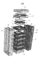
- FIG. 2 is a diagram (exploded view) showing an outline (overall configuration) of a thermoelectric generator according to an embodiment of the present invention.
- the thermoelectric generator 100 includes a laminated body in which each of a plurality of thermoelectric conversion modules 1 in the center is laminated on a frame member 2 having an opening through a rubber packing 3 and a laminated body Two fluid supply members 6 and 7 extending along two side surfaces are provided.
- An upper lid 4 whose upper surface is closed is joined to the lower frame member 2 via a rubber packing 3 at the top of the laminate.
- a lower lid 5 whose lower surface is closed is joined to the upper frame member 2 via a rubber packing 3 at the bottom of the laminate.
- the rubber packing 3 is disposed along the edge of the opening of the frame member 2 and is made of a sealing material having flexibility and sealing properties such as silicone and fluorine.
- each of the frame members 2 has a fluid injection hole 13 and a fluid discharge hole 12 reaching the opening on the side surface facing the fluid supply member 6 or 7 every other frame member.
- Each of the fluid supply members 6, 7 has fluid injection openings 9, 10 and fluid discharge openings 8, 11 extending along the side surfaces thereof.
- the side surfaces of the fluid supply members 6 and 7 facing the laminated body are aligned with the fluid injection holes 13 and the fluid discharge holes 12 on the side surfaces of the corresponding frame members, and the fluid injection openings 9 and 10 and the fluid discharge openings 8 and 11 are aligned.
- An injection hole 14 and a discharge hole 15 are provided.
- each of the fluid injection hole 13 and the fluid discharge hole 12 on the side surface of the frame member 2 is a first sealing material (reference numeral 32 in FIGS. 4 and 5) having an opening serving as a flow path at the center. )
- a first sealing material reference numeral 32 in FIGS. 4 and 5
- thermoelectric generator 100 of FIG. 2 ten thermoelectric conversion modules 1 in the laminate are included in total between the eleven frame members 2.
- the number of thermoelectric conversion modules 1 can be arbitrarily selected according to required power (voltage, current).
- the side surface of the laminated body on which the fluid supply members 6 and 7 are arranged is not limited to the two side surfaces facing each other in FIG. 2, and may be two adjacent side surfaces of the laminated body.
- either the high temperature or low temperature fluid is injected into the fluid injection openings 8 and 10 of the fluid supply members 6 and 7 through a pipe, and the fluid discharge opening 9 From 11, the high-temperature or low-temperature fluid circulated in the laminated body is collected through the pipe.
- two output lines are output from each of the thermoelectric conversion modules 1, and the generated power (voltage, current) can be obtained via the output lines.
- FIG. 3 is a diagram showing a configuration of the thermoelectric conversion module 1 according to an embodiment of the present invention.
- the upper substrate (lid) is omitted, but actually, it has a sealed structure sandwiched between two substrates having a lid function.
- a P-type thermoelectric conversion element 16 and an N-type thermoelectric conversion element 17 provided on a lower substrate (lid) 5 are arranged in series between an upper electrode 18 and a lower electrode 19. Having a ⁇ -type basic structure.
- the ⁇ -type basic structure is connected in series, and in the example of FIG. 3, the ⁇ -type basic structure has a total of 18 ⁇ -type basic structures (power generation units).
- Two output lines (+, ⁇ ) are provided at both ends of the thermoelectric conversion module 1 so that the generated power (voltage, current) can be acquired.
- the upper electrode 18 and the lower electrode 19 are made of materials having good electrical and thermal conductivity. For example, Cu is used. The thickness is, for example, about 1 mm in consideration of mechanical strength.
- the thermoelectric conversion module 1 can be used as a thermoelectric conversion module that generates a potential difference between two adjacent lower electrodes 19 when the upper electrode 18 side is heated to a high temperature and the lower electrode 19 side is cooled to a low temperature. it can.
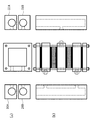
- FIG. 4 is a view showing a part (a) a top view and (b) a side view of a part of the thermoelectric generator according to an embodiment of the present invention.
- FIG. 4 shows an embodiment in which fluid supply members are arranged on two opposite side surfaces of the laminate.
- FIG. 4 shows a configuration including only two thermoelectric conversion modules 1 in order to explain the connection relationship of each component of the thermoelectric power generator according to an embodiment of the present invention. In this manner, a plurality of thermoelectric conversion modules 1 are further stacked.
- the fluid supply members 20 and 21 on both sides of the laminated body are illustrated to be separated from the laminated body, they are actually joined to the side surfaces of the laminated body. These points are the same in other embodiments of the present invention described with reference to FIGS.
- the upper thermoelectric conversion module 1 is located between the frame members 22 and 23 and is joined to these two frame members via the rubber packing 3.
- the lower thermoelectric conversion module 1 is located between the frame members 23 and 24 and is joined to these two frame members via the rubber packing 3.
- the frame members 22 and 24 have a fluid injection hole 30 and a fluid discharge hole 29 reaching the opening on the left side surface.
- the middle frame member 23 has a fluid injection hole 30 and a fluid discharge hole 29 (not shown) reaching the opening on the right side surface.
- the side facing the laminate of the left fluid supply member 20 is aligned with the fluid injection hole 30 and the fluid discharge hole 29 on the side surfaces of the frame members 22 and 24, and the injection reaches the fluid injection opening 9 and the fluid discharge opening 8.
- a hole 26 and a discharge hole 25 are provided.
- the side facing the laminate of the right fluid supply member 21 is aligned with the fluid injection hole 30 and the fluid discharge hole 29 on the side surface of the frame member 23, and the injection hole 27 reaching the fluid injection opening 10 and the fluid discharge opening 11.
- Each of the fluid injection holes 30 and the fluid discharge holes 29 on the side surfaces of the frame members 22 and 24 is aligned with the injection on the side surface of the fluid supply member 20 via a seal member 32 having an opening 33 serving as a flow path at the center.
- the hole 26 and the discharge hole 25 are joined to each other.
- each of the fluid injection hole 30 and the fluid discharge hole 29 on the side surface of the frame member 23 is aligned with the side surface of the fluid supply member 21 via a sealing material 32 having an opening 33 serving as a flow path at the center. It joins to each of the injection hole 27 and the discharge hole 28. For example, as shown in FIG.
- each of the sealing materials 32 has a through hole 33 at the center, and has a shape of any one of (a) a sphere, (b) a donut shape, (c) a cylinder, or (d) a rectangular parallelepiped.
- the elastic body for example, silicone rubber, fluororubber, etc. which has.
- Each of 30 and the fluid discharge hole 29 is provided with a recess in which the sealing material 32 is accommodated.
- the recess is provided in accordance with the shape of the sealing material 32. For example, when the shape of the sealing material 32 is a sphere in FIG. 5A, the recess has a hemispherical shape or a slightly smaller spherical shape.
- the through-holes 33 are aligned so as to face each hole so that the through-holes 33 become a part of the fluid flow path.
- the through-hole 33 of the sealing material 32 becomes a part of the fluid flow path between the fluid supply member and the frame member.
- the fluid supply member 20 and the laminate are joined from the outside to the inside while inserting the screw 44 into the screw hole 40 provided in the fluid supply member 20 and the screw hole 41 provided on the left side surface of each frame member. By doing. Similarly, the fluid supply member 21 and the laminate are joined from the outside to the inside while inserting the screw 45 into the screw hole 43 provided in the fluid supply member 21 and the screw hole 42 provided in the right side surface of each frame member. Do by tightening toward. By the tightening, the sealing material 32 is crushed and a sealing function is exhibited, and the fluid can move between the fluid supply member and the frame member without leaking to the outside.
- thermoelectric conversion module 1 There is an upper lid 4 at the top of the laminate and a lower lid 5 at the bottom. At the four corners of the upper lids 4 and 5 and the frame members 22, 23 and 24, there are holes 46 aligned in the vertical direction.
- the laminated body is fastened by a bolt 47 inserted in the hole 46 between the upper lid 4 and the lower lid 5.
- the rubber packing 3 is crushed to a thickness of about 90% of its original thickness, for example, so that the sealing function is sufficiently exerted so that the high-temperature and low-temperature fluids reliably reach each thermoelectric conversion module 1. become.
- the thermoelectric conversion module 1, the frame members 22, 23, 24 and the rubber packing 3 are securely fastened with bolts penetrating in the vertical direction using the holes 46 provided at the four corners of the frame member. Since a uniform pressure is applied to the thermoelectric conversion module and any frame member and non-uniform tightening does not occur, damage to the thermoelectric conversion module 1 is also avoided.
- FIG. 6 shows (a) a top view and (b) a side view of a part of a thermoelectric generator according to another embodiment of the present invention.
- the configuration of FIG. 6 is basically the same as the configuration of the embodiment in the case where the fluid supply member is disposed on the two opposing side surfaces of the laminate of FIG. 4, but the frame members 22, 23, and 24 and the thermoelectric conversion The difference is that there is no rubber packing 3 between the module 1 and the module 1. That is, in FIG. 6, the frame members 22, 23, and 24 and the thermoelectric conversion module 1 are directly joined. In this case, since there is no rubber packing 3, the sealing function is inferior compared to the case of FIG.
- thermoelectric conversion module 4 but if a highly water-resistant product is used for the thermoelectric conversion module 1, there is some leakage due to insufficient sealing function. However, the possibility of adverse effects such as water intrusion into the thermoelectric conversion module is extremely low. On the other hand, fluid leakage to the outside of the thermoelectric generator may occur, but depending on the usage environment of the thermoelectric generator, for example, there is originally water, in other words, there is no problem even if there is some water leak There is also an environment, so it can be used in such an environment.
- FIG. 7 shows a fluid path (flow) in the thermoelectric generator of the embodiment of FIG. The same applies to the embodiment of FIG. 4, and the basic fluid path is the same in other embodiments described later.
- cold water supplied from the fluid injection opening 9 of the left fluid supply member 20 is injected into the frame members 22 and 24.
- the injected cold water moves through the openings in the frame members 22, 24 as indicated by arrows as shown in the cross-section 1-1 ′, returns to the fluid supply member 20, and is recovered from the fluid discharge opening 8.
- the hot water supplied from the fluid injection opening 10 of the right fluid supply member 21 is injected into the middle frame member 23.
- the injected hot water moves through the opening in the frame member 23 as indicated by the arrow as shown in the section 2-2 ′, returns to the fluid supply member 21, and is recovered from the fluid discharge opening 11.
- the hot water and the cold water are supplied to the fluid supply members 20 and 21 with a predetermined water pressure by a pump or the like. This also applies to other embodiments.
- the upper surface and the lower surface of the thermoelectric conversion module 1 can be cooled or heated.
- the thermoelectric conversion module 1 can be generated as described with reference to FIG.
- hot water may be supplied to the fluid supply member 20 and cold water may be supplied to the fluid supply member 21.
- FIG. 8 shows (a) a top view and (b) a side view of a part of a thermoelectric generator according to another embodiment of the present invention.
- the configuration of FIG. 8 is basically the same as the configuration of the embodiment in which the fluid supply members are arranged on two opposite side surfaces of the laminate of FIG. 4, but two fluid supply members are provided on each side surface. (4 in total) Different in arrangement. That is, in FIG. 8, two fluid supply members 20A and 20B are arranged on the left side surface of the laminate, and two fluid supply members 21A and 21B are arranged on the right side surface of the laminate.
- the left fluid supply member 20B is for fluid injection (for example, cold water injection), and the fluid supply member 20A is for fluid recovery (for example, cold water recovery).
- the right fluid supply member 21A is for fluid injection (for example, hot water injection), and the fluid supply member 21B is for fluid recovery (for example, hot water recovery).
- the fluid path is basically the same as in FIG. 7 except that the fluid supply member is separated for fluid injection and fluid recovery.
- FIG. 9 shows (a) a top view and (b) a side view of a part of a thermoelectric generator according to another embodiment of the present invention.
- a pair of fluid supply members 20A and 20B are arranged so as to face the left and right side surfaces facing each other as shown in the cross section 1-1 ′.
- the other pair of fluid supply members 21A and 21B are arranged so as to face the front and rear side surfaces of the laminate as shown in the cross-sectional view 2-2 ′.
- the fluid supply member 20A shown in the section 1-1 ′ is for fluid injection (for example, cold water injection), and the fluid supply member 20B is for fluid recovery (for example, cold water recovery).
- the fluid supply member 21A shown in the section 2-2 ' is for fluid injection (for example, hot water injection)
- the fluid supply member 21B is for fluid recovery (for example, hot water recovery). In either group, injection and recovery may be reversed.
- the cold water supplied from the fluid injection opening 9 of the fluid supply member 20A is injected into the frame members 22 and 24.
- the injected cold water moves through the openings in the frame members 22 and 24, returns to the fluid supply member 20B, and is collected from the fluid discharge opening 8, as indicated by the arrow in the section 1-1 ′.
- the hot water supplied from the fluid injection opening 10 of the fluid supply member 21A is injected into the middle frame member 23.
- the injected hot water moves through the opening in the frame member 23 and returns to the fluid supply member 21B and is collected from the fluid discharge opening 11 as shown by the arrow in the section 2-2 ′.
- the upper and lower surfaces of the thermoelectric conversion module are obtained by alternately injecting cold water and hot water into every other frame member by two sets of opposing fluid supply members, as in the other embodiments. Can be cooled or heated.
- FIG. 10 shows (a) a top view, (b) a side view, and (c) a surface view of a part of a thermoelectric generator according to another embodiment of the present invention.
- one fluid supply member 50 is disposed on the left side surface of the laminate.
- the fluid supply member 50 is joined to each frame member by tightening inward from the outside while inserting the screws 56 and 57 into the screw holes 58 and 59 provided in the fluid supply member 50 and the frame members 22 to 24.
- the fluid supply member 50 has two fluid injection openings 51 and 53 and two fluid discharge openings 52 and 54.
- a pair of fluid injection openings 51 and fluid discharge openings 52 are formed by sealing materials 32 having through-holes 33 in the openings of the two frame members 22, 24. And a continuous flow path is formed.
- the other set of fluid injection opening 53 and fluid discharge opening 54 are connected to each other through the seal member 32 having the opening 33 in the opening of one frame member 23 to form a continuous flow path.
- the cold water supplied from the fluid injection opening 51 of the fluid supply member 50 is injected into the frame members 22 and 24.
- the injected cold water moves through the openings in the frame members 22, 24 as indicated by arrows as shown in the cross-section 1-1 ′, returns to the fluid supply member 50, and is recovered from the fluid discharge opening 52. .
- the hot water supplied from the fluid injection opening 53 of the fluid supply member 50 is injected into the middle frame member 23.
- the injected hot water moves through the opening in the frame member 23 as shown by an arrow as shown in the section 2-2 ′, returns to the fluid supply member 50, and is recovered from the fluid discharge opening 54.
- the upper surface and the lower surface of the thermoelectric conversion module are cooled by alternately injecting cold water and hot water into every other frame member, as in the case of the other embodiments. Or it can be heated.
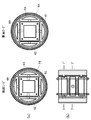
- FIG. 11 shows (a) a top view and (b) a side view of a part of a thermoelectric generator according to another embodiment of the present invention.
- the pair of fluid supply members 60 and 61 faces the front and rear side surfaces facing each other as shown in FIG. Be placed.
- the other pair of fluid supply members 62 and 63 are disposed so as to face the left and right side surfaces of the laminate as shown in the cross-sectional view 2-2 ′.
- the cross section of each fluid supply member has a flat portion facing the laminate and a circular portion forming an outer shape.
- the central laminated body is surrounded by four fluid supply members 60 to 63, so that a single cylindrical shape is formed as a whole.
- the fluid supply member 60 is for fluid injection (for example, cold water injection), and the fluid supply member 61 is for fluid recovery (for example, cold water recovery).
- the fluid supply member 62 is for fluid injection (for example, hot water injection), and the fluid supply member 63 is for fluid recovery (for example, hot water recovery). In either group, injection and recovery may be reversed.
- the flow paths of cold water and hot water are the same as in the case of FIG.
- FIG. 12 is a diagram illustrating a state during power generation of the thermoelectric power generator according to the embodiment of the present invention.
- the thermoelectric generator of FIG. 12 includes eleven frame members 2 and ten thermoelectric conversion modules 1 between the upper lid 4 and the lower lid 5.
- the upper and lower surfaces of the thermoelectric conversion module 1 are cooled or heated to generate electricity.
- Output voltages V 1 to V 10 are obtained from the respective output lines of the thermoelectric conversion module 1.
- thermoelectric power generation apparatus according to an embodiment of the present invention shown in FIG. 12 was actually made and the output voltages V 1 to V 10 from each thermoelectric conversion module were measured.
- Ten thermoelectric modules having a thickness of 3.6 mm and 40 mm square were used for the thermoelectric conversion module 1.
- Engineering fluid was used for the fluid supply members 6 and 7 and the frame member 2.
- Silicone rubber was used for the rubber packing 3 and the sealing material 32.
- supply cold water of 10 ° C and hot water whose temperature is changed at intervals of 15 ° C from 35 ° C to 95 ° C while changing the flow rate to 3, 5, 7 (L / min).
- the output voltage (V) of each thermoelectric conversion module 1 was measured. Tables 1 to 3 below show output voltages (V) when the flow rates are 3, 5, and 7 (L / min) in order.
- thermoelectric generator of the present invention can be widely used industrially as a small and highly expandable thermoelectric generator.
Landscapes
- Electrolytic Production Of Non-Metals, Compounds, Apparatuses Therefor (AREA)
- Hybrid Cells (AREA)
Abstract
本発明の熱電発電装置は、複数の熱電変換モジュールの各々が開口部を有する枠部材2に挟まれるようにして積層された積層体と、積層体の異なる側面に沿って延びるように設けられた少なくとも2つの流体供給部材とを備える。さらに、枠部材の各々は、一つ置きに異なる流体供給部材に面する側面に開口部に至る流体注入孔と流体排出孔を有し、流体供給部材の各々は、その側面に沿って延びる流体注入開口及び流体排出開口の一方または双方を有し、各流体供給部材の側面には、対応する枠部材の側面の流体注入孔または流体排出孔に位置合わせされ、流体注入開口または流体排出開口に至る注入孔または排出孔が設けられ、枠部材の側面の流体注入孔と流体排出孔の各々は、中央に流路となる開口を有する第1のシール材を介して、流体供給部材の側面の位置合わせされた注入孔と排出孔の各々に接合する。
Description
本発明は、熱電発電装置に関し、より具体的には、複数の熱電変換モジュールを搭載した熱電発電装置に関する。
熱電変換技術とは、固体の熱電変換素子を用いて熱エネルギーと電気エネルギーを相互に変換する技術である。熱エネルギーを電気エネルギーに変換する技術は、熱電発電と呼ばれ、熱電効果の1つであるゼーベック効果に基づく。熱電発電では、熱電変換素子の両端間の温度差が電気エネルギーに直接変換される。この熱電発電を利用して、工場や自動車から排出されている膨大な未利用熱エネルギーを回収し、そこから電力を生み出すことで、化石燃料の消費量低減、更にはCO2削減と省エネルギーに大いに貢献できる。
熱電変換素子は、一般に熱電変換材料が2つの電極で挟持された構成を有する。その熱電変換素子を用いて熱電変換モジュールを構成することができる。具体的には、例えば、P型熱電変換素子(電荷を運ぶキャリアが正孔)と、N型熱電変換素子(電荷を運ぶキャリアが電子)を、上部接合電極と下部接合電極を用いて熱的には並列に電気的には直列に接続することにより、熱電変換モジュールを得る。熱電変換モジュールはP-N熱電変換素子一対でも熱電変換モジュールとして機能するが、通常、より大きな出力を得るために、複数のP-N対の熱電変換モジュールを組み合わせて、熱電発電装置を構成する。
図1に従来からある熱電発電装置の構成例を示す。図1では、熱源となるガスや流体から熱電変換モジュール60に熱を伝達するための熱交換器62と組み合わせて熱電発電装置を構築している。このように、従来の方法では、必要となる電力(電圧と電流)を得るために、複数の熱電変換モジュールを使用して、その出力を直列あるいは並列に接続して、熱電発電装置とする場合が一般的である。
しかし、図1に示すような従来の一般的な熱電発電装置では、複数の熱電変換モジュール60を熱交換器62の間に挟み込み、確実に伝熱する設計をするためには、単位面積あたりの荷重として0.5Mpa~1MPa程度の圧力が必要であり、これに耐える熱交換器構造にする必要がある。このため熱交換器62は頑丈な構造とならざるを得ず、その結果コストが高くなる。さらに、他の問題点として、熱交換器62の面積(伝熱面64)が広い場合、熱電変換モジュール60を挟みこむ圧力に分布が生じるため、伝熱のよい熱電変換モジュールと伝熱の悪い熱電変換モジュールが発生し、発電出力が低下する。圧力の分布が大きな場合は熱電変換モジュールの破損につながることもある。
複数の熱電変換モジュールに対して均一な圧力で固定し、均一に熱源からの熱を伝えて発電する熱電発電装置を少ない部品点数で実現することが、熱電発電技術を低コスト化するために必要となっている。特許文献1は、1つの熱電モジュール270aの両側がプレート202及び流体攪乱プレート240で挟まれた基本(内部)構成110を備え、プレート202の表面に設けられたガスケット304によって流体のシール及びプレート202の表面を流れる流体(高温または低温)の切り替えを交互に行うプレート型の熱電変換器200を開示する。
特許文献1のプレート型の熱電変換器では、プレートを重ねて全体を構成するので、全体がコンパクトに集約されるが、1つのプレート202の表面の4端の孔に高温と低温の2つの流体が流れるので、ガスケット304によるシール効果が不十分だと両方の流体が1つのプレート202の表面に混在してしまう恐れがある。すなわち、高温と低温の2つの流体の経路が完全に分離されていないので、熱電モジュールへの流体による温度差の提供が不十分になる恐れがある。
本発明は、高温と低温の2つの流体の経路が完全に分離され、複数の熱電変換モジュールに対して均一に熱源からの熱を伝えて発電することができる、拡張性がありかつコンパクトな熱電発電装置を提供することを目的とする。
本発明の一態様では、複数の熱電変換モジュールの各々が開口部を有する枠部材に挟まれるようにして積層された積層体と、積層体の異なる側面に沿って延びるように設けられた少なくとも2つの流体供給部材と、を備える熱電発電装置を提供する。
その熱電発電装置において、枠部材の各々は、一つ置きに異なる流体供給部材に面する側面に開口部に至る流体注入孔と流体排出孔を有し、流体供給部材の各々は、その側面に沿って延びる流体注入開口及び流体排出開口の一方または双方を有し、各流体供給部材の側面には、対応する枠部材の側面の流体注入孔または流体排出孔に位置合わせされ、流体注入開口または流体排出開口に至る注入孔または排出孔が設けられ、枠部材の側面の流体注入孔と流体排出孔の各々は、中央に流路となる開口を有する第1のシール材を介して、流体供給部材の側面の位置合わせされた注入孔と排出孔の各々に接合する、熱電発電装置。
その熱電発電装置において、枠部材の各々は、一つ置きに異なる流体供給部材に面する側面に開口部に至る流体注入孔と流体排出孔を有し、流体供給部材の各々は、その側面に沿って延びる流体注入開口及び流体排出開口の一方または双方を有し、各流体供給部材の側面には、対応する枠部材の側面の流体注入孔または流体排出孔に位置合わせされ、流体注入開口または流体排出開口に至る注入孔または排出孔が設けられ、枠部材の側面の流体注入孔と流体排出孔の各々は、中央に流路となる開口を有する第1のシール材を介して、流体供給部材の側面の位置合わせされた注入孔と排出孔の各々に接合する、熱電発電装置。
本発明の他の一態様では、複数の熱電変換モジュールの各々が開口部を有する枠部材に挟まれるようにして積層された積層体と、積層体の1つの側面に沿って延びるように設けられた1つの流体供給部材と、を備える熱電発電装置を提供する。
その熱電発電装置において、枠部材の各々は、流体供給部材に面する側面に開口部に至る流体注入孔と流体排出孔を有し、枠部材の一つ置きに流体注入孔と流体排出孔が枠部材の側面の異なる位置にあり、流体供給部材は、その側面に沿って延びる2組の流体注入開口及び流体排出開口を有し、流体供給部材の側面には、各枠部材の側面の流体注入孔と流体排出孔に位置合わせされ、対応する流体注入開口と流体排出開口に至る注入孔と排出孔が設けられ、枠部材の側面の流体注入孔と流体排出孔の各々は、中央に流路となる開口を有するシール材を介して、流体供給部材の側面の位置合わせされた注入孔と排出孔の各々に接合する。
その熱電発電装置において、枠部材の各々は、流体供給部材に面する側面に開口部に至る流体注入孔と流体排出孔を有し、枠部材の一つ置きに流体注入孔と流体排出孔が枠部材の側面の異なる位置にあり、流体供給部材は、その側面に沿って延びる2組の流体注入開口及び流体排出開口を有し、流体供給部材の側面には、各枠部材の側面の流体注入孔と流体排出孔に位置合わせされ、対応する流体注入開口と流体排出開口に至る注入孔と排出孔が設けられ、枠部材の側面の流体注入孔と流体排出孔の各々は、中央に流路となる開口を有するシール材を介して、流体供給部材の側面の位置合わせされた注入孔と排出孔の各々に接合する。
図面を参照しながら本発明の実施形態について説明する。図2は、本発明の一実施形態の熱電発電装置の概要(全体構成)を示す図(分解図)である。図2では、その内部構成がわかるように、熱電発電装置100の上部と側面を分解し離間した状態を示している。熱電発電装置100は、中央にある複数の熱電変換モジュール1の各々が開口部を有する枠部材2にゴム製パッキン3を介して上下に挟まれるようにして積層された積層体と、積層体の2つの側面に沿って延びる2つの流体供給部材6、7を備える。積層体の最上部には上面が閉じた上蓋4がゴム製パッキン3を介してその下の枠部材2に接合する。同様に、積層体の最下部には下面が閉じた下蓋5がゴム製パッキン3を介してその上の枠部材2に接合する。ゴム製パッキン3は、枠部材2の開口部の縁に沿って配置され、例えばシリコーンやフッ素のような柔軟性とシール性を有するシール材からなる。
熱電発電装置100において、枠部材2の各々は、一つ置きに流体供給部材6または7に面する側面に開口部に至る流体注入孔13と流体排出孔12を有する。流体供給部材6、7の各々は、その側面に沿って延びる流体注入開口9、10及び流体排出開口8、11を有する。流体供給部材6、7の積層体に面する側面には、対応する枠部材の側面の流体注入孔13と流体排出孔12に位置合わせされ、流体注入開口9、10と流体排出開口8、11に至る注入孔14と排出孔15が設けられている。なお、詳細は後述するが、枠部材2の側面の流体注入孔13と流体排出孔12の各々は、中央に流路となる開口を有する第1のシール材(図4や図5の符号32)を介して、流体供給部材6、7の側面の位置合わせされた注入孔14と排出孔15の各々に接合する。
図2の熱電発電装置100では、積層体中の熱電変換モジュール1は、11個の枠部材2の間に合計で10個含まれている。熱電変換モジュール1の数は、必要となる電力(電圧、電流)に応じて任意に選択することができる。また、流体供給部材6、7が配置される積層体の側面は、図2の向かい合う2つの側面に限定されず、積層体の隣接する2側面であってもよい。なお、図示はしていないが、流体供給部材6、7の流体注入開口8、10には配管を介して高温または低温のいずれかの流体が注入されるようになっており、流体排出開口9、11からは積層体内を循環した高温または低温の流体が配管を介して回収されるようになっている。さらに、熱電変換モジュール1の各々からは2本の出力線が出ており、発電した電力(電圧、電流)が出力線を介して得られるようになっている。
図3は、本発明の一実施形態の熱電変換モジュール1の構成を示す図である。図3では、上側の基板(蓋)を省略しているが、実際には蓋の機能を備える2つの基板に挟まれた密封された構造をしている。熱電変換モジュール1は、下側の基板(蓋)5上に設けられた、P型熱電変換素子16とN型熱電変換素子17が上側の電極18と下側の電極19の間に直列に配置されたπ型の基本構造を有する。π型の基本構造は直列に接続されて、図3の例では全体で18個のπ型の基本構造(発電部)を有する。熱電変換モジュール1の両端には2本の出力線(+、-)が設けられており、発電した電力(電圧、電流)を取得できるようになっている。
上側の電極18と下側の電極19には、電気的、熱的な伝導性の良い材料が使用される。例えばCuなどが使われる。その厚さは、機械的な強度も考慮して、例えば1mm程度である。熱電変換モジュール1においては、上側の電極18側を高温にし、下側の電極19側を低温にすると、隣接する2つの下側の電極19間に電位差を生じさせる熱電変換モジュールとして利用することができる。
<第1実施形態>
図4は、本発明の一実施形態の熱電発電装置の一部の(a)上面図と(b)側面図を示す図である。図4は、積層体の対向する2つの側面に流体供給部材が配置される場合の実施形態を示す。図4は、本発明の一実施形態の熱電発電装置の各部品の接続関係を説明するために、2つの熱電変換モジュール1のみを含む構成を示しているが、実際には図2に例示したようにさらに複数の熱電変換モジュール1が積層される。また、積層体の両側の流体供給部材20、21は、積層体から離間して記載されているが、実際には積層体の側面に接合する。なお、これらの点は、図6~図11を参照しながら説明する本発明の他の実施形態においても同様である。
図4は、本発明の一実施形態の熱電発電装置の一部の(a)上面図と(b)側面図を示す図である。図4は、積層体の対向する2つの側面に流体供給部材が配置される場合の実施形態を示す。図4は、本発明の一実施形態の熱電発電装置の各部品の接続関係を説明するために、2つの熱電変換モジュール1のみを含む構成を示しているが、実際には図2に例示したようにさらに複数の熱電変換モジュール1が積層される。また、積層体の両側の流体供給部材20、21は、積層体から離間して記載されているが、実際には積層体の側面に接合する。なお、これらの点は、図6~図11を参照しながら説明する本発明の他の実施形態においても同様である。
上側の熱電変換モジュール1は、枠部材22と23の間にあって、ゴム製パッキン3を介してこれら2つの枠部材に接合する。同様に、下側の熱電変換モジュール1は、枠部材23と24の間にあって、ゴム製パッキン3を介してこれら2つの枠部材に接合する。枠部材22と24は、左側の側面に開口部に至る流体注入孔30と流体排出孔29を有する。真中の枠部材23は、右側の側面に開口部に至る流体注入孔30と流体排出孔29(図示なし)を有する。左側の流体供給部材20の積層体に面する側面には、枠部材22と24の側面の流体注入孔30と流体排出孔29に位置合わせされ、流体注入開口9と流体排出開口8に至る注入孔26と排出孔25が設けられている。右側の流体供給部材21の積層体に面する側面には、枠部材23の側面の流体注入孔30と流体排出孔29に位置合わせされ、流体注入開口10と流体排出開口11に至る注入孔27と排出孔28が設けられている。
枠部材22と24の側面の流体注入孔30と流体排出孔29の各々は、中央に流路となる開口33を有するシール材32を介して、流体供給部材20の側面の位置合わせされた注入孔26と排出孔25の各々に接合する。同様に、枠部材23の側面の流体注入孔30と流体排出孔29の各々は、中央に流路となる開口33を有するシール材32を介して、流体供給部材21の側面の位置合わせされた注入孔27と排出孔28の各々に接合する。シール材32は、例えば図5に示すように、いずれも中央に貫通孔33を有する、(a)球、(b)ドーナツ形、(c)円柱、あるいは(d)直方体のいずれかの形状を有する弾性体(例えばシリコーンゴムやフッ素ゴム等)からなる。
流体供給部材20の注入孔26と排出孔25、流体供給部材21の注入孔27と排出孔28、枠部材22と24の流体注入孔30と流体排出孔29、及び枠部材23の流体注入孔30と流体排出孔29の各々には、シール材32が収まる凹部が設けられている。凹部は、シール材32の形状に合せて設けられる。例えば、シール材32の形状が図5の(a)球の場合、凹部は半球状あるいはそれよりやや小さい球状を有する。これらの各孔の凹部にシール材32が収められる際に、貫通孔33が流体の流路の一部となるように、貫通孔33が各孔に正対するように位置合わせされる。その結果、シール材32の貫通孔33が流体供給部材と枠部材との間の流体の流路の一部となる。このようにシール材32を用いることにより、ホース等の接続を不要とし、部品点数を大幅に削減すると同時に熱電発電装置全体のサイズをよりコンパクトにすることができる。
流体供給部材20と積層体の接合は、流体供給部材20に設けられたネジ孔40と各枠部材の左側面に設けられたネジ孔41にネジ44を挿入しながら外側から内側に向かって締め付けることにより行う。同様に、流体供給部材21と積層体の接合は、流体供給部材21に設けられたネジ孔43と各枠部材の右側面に設けられたネジ孔42にネジ45を挿入しながら外側から内側に向かって締め付けることにより行う。その締め付けにより、シール材32が潰れてシール機能が発揮され、流体が外部に漏れることなく流体供給部材と枠部材との間を移動することができる。
積層体の最上部には上蓋4があり、最下部には下蓋5がある。上蓋4、5と、枠部材22、23、24の4隅には垂直方向で位置合わせされた孔46がある。積層体は、上蓋4と下蓋5の間で孔46内に挿入されたボルト47によって締め付けられる。その締め付けによって、ゴム製パッキン3が例えばその本来の厚みの約90%の厚みまで潰れることにより、シール機能を十分に発揮させて、高温及び低温の流体が確実に各熱電変換モジュール1に届くようになる。熱電変換モジュール1、枠部材22、23、24、及びゴム製パッキン3は、枠部材の4隅に設けられた孔46を使用して縦方向に貫通したボルトで確実に締結されるため、どの熱電変換モジュール、どの枠部材にも均一な圧力が加わり、不均一な締め上げなどが発生しないため、熱電変換モジュール1の破損も回避される。
<第2実施形態>
図6に本発明の他の一実施形態の熱電発電装置の一部の(a)上面図と(b)側面図を示す。図6の構成は、基本的に図4の積層体の対向する2つの側面に流体供給部材が配置される場合の実施形態の構成と同様であるが、枠部材22、23、24と熱電変換モジュール1との間にゴム製パッキン3が無い点が異なっている。すなわち、図6では、枠部材22、23、24と熱電変換モジュール1とが直接接合する。この場合、ゴム製パッキン3が無いので、図4の場合に比べてシール機能が劣るが、熱電変換モジュール1に耐水性の高い製品を使用すれば、シール機能不足による多少の漏水があったとしても熱電変換モジュール内部への浸水等の悪影響が起こる可能性は極めて低い。一方、熱電発電装置の外部への流体の漏れは起こる可能性があるが、熱電発電装置の使用環境によっては、例えば元々水気のある、言い換えれば多少の水漏れがあっても問題無いような使用環境もあるので、そうした環境で使用することができる。
図6に本発明の他の一実施形態の熱電発電装置の一部の(a)上面図と(b)側面図を示す。図6の構成は、基本的に図4の積層体の対向する2つの側面に流体供給部材が配置される場合の実施形態の構成と同様であるが、枠部材22、23、24と熱電変換モジュール1との間にゴム製パッキン3が無い点が異なっている。すなわち、図6では、枠部材22、23、24と熱電変換モジュール1とが直接接合する。この場合、ゴム製パッキン3が無いので、図4の場合に比べてシール機能が劣るが、熱電変換モジュール1に耐水性の高い製品を使用すれば、シール機能不足による多少の漏水があったとしても熱電変換モジュール内部への浸水等の悪影響が起こる可能性は極めて低い。一方、熱電発電装置の外部への流体の漏れは起こる可能性があるが、熱電発電装置の使用環境によっては、例えば元々水気のある、言い換えれば多少の水漏れがあっても問題無いような使用環境もあるので、そうした環境で使用することができる。
図7に図6の実施形態の熱電発電装置における流体の経路(流れ)を示す。図4の実施形態においても同様であり、後述する他の実施形態においても基本的な流体の経路は同様である。図7において、左側の流体供給部材20の流体注入開口9から供給される冷水は、枠部材22、24内に注入される。注入された冷水は、断面1-1´図に示されるように、枠部材22、24内の開口中を矢印のように移動して流体供給部材20へ戻り、流体排出開口8から回収される。同様に、右側の流体供給部材21の流体注入開口10から供給される温水は、真中の枠部材23内に注入される。注入された温水は、断面2-2´図に示されるように、枠部材23内の開口中を矢印のように移動して流体供給部材21へ戻り、流体排出開口11から回収される。
なお、図示はしていないが、流体供給部材20、21への温水及び冷水の供給は、ポンプ等により所定の水圧を持って行われるようになっている。この点、他の実施形態においても同様である。このように枠部材の一つ置きに冷水と温水を交互に注入することにより、熱電変換モジュール1の上面と下面を冷却または加熱することができる。その結果、図3を参照しながら説明したように、熱電変換モジュール1を発電させることができる。なお、図7の熱電変換モジュール1の構成に応じて、流体供給部材20へ温水を供給し、流体供給部材21へ冷水を供給する場合もある。
<第3実施形態>
図8に本発明の他の一実施形態の熱電発電装置の一部の(a)上面図と(b)側面図を示す。図8の構成は、基本的に図4の積層体の対向する2つの側面に流体供給部材が配置される場合の実施形態の構成と同様であるが、流体供給部材が各側面に2つずつ(計4つ)配置される点が異なっている。すなわち、図8では、積層体の左側面に2つの流体供給部材20Aと20Bが配置され、積層体の右側面に2つの流体供給部材21Aと21Bが配置される。左側の流体供給部材20Bは流体注入(例えば冷水注入)用であり、流体供給部材20Aは流体回収(例えば冷水回収)用である。同様に、右側の流体供給部材21Aは流体注入(例えば温水注入)用であり、流体供給部材21Bは流体回収(例えば温水回収)用である。流体供給部材が流体注入用と流体回収用に分離されている点を除いて、流体の経路は基本的に図7の場合と同様である。
図8に本発明の他の一実施形態の熱電発電装置の一部の(a)上面図と(b)側面図を示す。図8の構成は、基本的に図4の積層体の対向する2つの側面に流体供給部材が配置される場合の実施形態の構成と同様であるが、流体供給部材が各側面に2つずつ(計4つ)配置される点が異なっている。すなわち、図8では、積層体の左側面に2つの流体供給部材20Aと20Bが配置され、積層体の右側面に2つの流体供給部材21Aと21Bが配置される。左側の流体供給部材20Bは流体注入(例えば冷水注入)用であり、流体供給部材20Aは流体回収(例えば冷水回収)用である。同様に、右側の流体供給部材21Aは流体注入(例えば温水注入)用であり、流体供給部材21Bは流体回収(例えば温水回収)用である。流体供給部材が流体注入用と流体回収用に分離されている点を除いて、流体の経路は基本的に図7の場合と同様である。
<第4実施形態>
図9に本発明の他の一実施形態の熱電発電装置の一部の(a)上面図と(b)側面図を示す。図9の構成では、1組の流体供給部材20Aと20Bが、断面1-1´図に示されるように、積層体の対向する左右の側面に向かい合うように配置される。同様に、他の組の流体供給部材21Aと21Bが、断面2-2´図に示されるように、積層体の対向する前後の側面に向かい合うように配置される。断面1-1´図の流体供給部材20Aは流体注入(例えば冷水注入)用であり、流体供給部材20Bは流体回収(例えば冷水回収)用である。同様に、断面2-2´図の流体供給部材21Aは流体注入(例えば温水注入)用であり、流体供給部材21Bは流体回収(例えば温水回収)用である。なお、いずれの組においても注入用と回収用は反対でもよい。
図9に本発明の他の一実施形態の熱電発電装置の一部の(a)上面図と(b)側面図を示す。図9の構成では、1組の流体供給部材20Aと20Bが、断面1-1´図に示されるように、積層体の対向する左右の側面に向かい合うように配置される。同様に、他の組の流体供給部材21Aと21Bが、断面2-2´図に示されるように、積層体の対向する前後の側面に向かい合うように配置される。断面1-1´図の流体供給部材20Aは流体注入(例えば冷水注入)用であり、流体供給部材20Bは流体回収(例えば冷水回収)用である。同様に、断面2-2´図の流体供給部材21Aは流体注入(例えば温水注入)用であり、流体供給部材21Bは流体回収(例えば温水回収)用である。なお、いずれの組においても注入用と回収用は反対でもよい。
図9において、流体供給部材20Aの流体注入開口9から供給される冷水は、枠部材22、24内に注入される。注入された冷水は、断面1-1´図の矢印で示されるように、枠部材22、24内の開口中を移動して流体供給部材20Bへ戻り、流体排出開口8から回収される。同様に、流体供給部材21Aの流体注入開口10から供給される温水は、真中の枠部材23内に注入される。注入された温水は、断面2-2´図の矢印で示されるように、枠部材23内の開口中を移動して流体供給部材21Bへ戻り、流体排出開口11から回収される。本実施形態では、2組の対向する流体供給部材により、他の実施形態の場合と同様に、枠部材の一つ置きに冷水と温水を交互に注入することにより、熱電変換モジュールの上面と下面を冷却または加熱することができる。
<第5実施形態>
図10に本発明の他の一実施形態の熱電発電装置の一部の(a)上面図と(b)側面図と(c)表面図を示す。図10の構成では、1つの流体供給部材50が、積層体の左側面に配置される。流体供給部材50は、流体供給部材50と枠部材22~24に設けられたネジ孔58、59にネジ56、57を挿入しながら外側から内側に向かって締め付けることにより、各枠部材と接合する。(a)の断面1-1´及び2-2´図に示されるように、流体供給部材50は、2つの流体注入開口51、53と、2つの流体排出開口52、54を有する。(c)の表面3-3´図に示されるように、1組の流体注入開口51と流体排出開口52は、2つの枠部材22、24の開口内と貫通孔33を有するシール材32を介して繋がり連続した流路を形成する。同様に、他の1組の流体注入開口53と流体排出開口54は、1つの枠部材23の開口内と開口33を有するシール材32を介して繋がり連続した流路を形成する。
図10に本発明の他の一実施形態の熱電発電装置の一部の(a)上面図と(b)側面図と(c)表面図を示す。図10の構成では、1つの流体供給部材50が、積層体の左側面に配置される。流体供給部材50は、流体供給部材50と枠部材22~24に設けられたネジ孔58、59にネジ56、57を挿入しながら外側から内側に向かって締め付けることにより、各枠部材と接合する。(a)の断面1-1´及び2-2´図に示されるように、流体供給部材50は、2つの流体注入開口51、53と、2つの流体排出開口52、54を有する。(c)の表面3-3´図に示されるように、1組の流体注入開口51と流体排出開口52は、2つの枠部材22、24の開口内と貫通孔33を有するシール材32を介して繋がり連続した流路を形成する。同様に、他の1組の流体注入開口53と流体排出開口54は、1つの枠部材23の開口内と開口33を有するシール材32を介して繋がり連続した流路を形成する。
図10において、流体供給部材50の流体注入開口51から供給される冷水は、枠部材22、24内に注入される。注入された冷水は、断面1-1´図に示されるように、枠部材22、24内の開口中を矢印のように移動して流体供給部材50へ戻り、流体排出開口52から回収される。同様に、流体供給部材50の流体注入開口53から供給される温水は、真中の枠部材23内に注入される。注入された温水は、断面2-2´図に示されるように、枠部材23内の開口中を矢印のように移動して流体供給部材50へ戻り、流体排出開口54から回収される。本実施形態では、1つの流体供給部材50により、他の実施形態の場合と同様に、枠部材の一つ置きに冷水と温水を交互に注入することにより、熱電変換モジュールの上面と下面を冷却または加熱することができる。
<第6実施形態>
図11に本発明の他の一実施形態の熱電発電装置の一部の(a)上面図と(b)側面図を示す。図11の構成では、図9の実施形態と同様に、1組の流体供給部材60と61が、断面1-1´図に示されるように、積層体の対向する前後の側面に向かい合うように配置される。同様に、他の組の流体供給部材62と63が、断面2-2´図に示されるように、積層体の対向する左右の側面に向かい合うように配置される。各流体供給部材の断面は、積層体に面する平坦部と外形を成す円形部を有する。図11の熱電発電装置では、中央の積層体を4つの流体供給部材60~63で取り囲み、全体で1つの円筒形を成す態様を示している。流体供給部材60は流体注入(例えば冷水注入)用であり、流体供給部材61は流体回収(例えば冷水回収)用である。同様に、流体供給部材62は流体注入(例えば温水注入)用であり、流体供給部材63は流体回収(例えば温水回収)用である。なお、いずれの組においても注入用と回収用は反対でもよい。冷水及び温水の流路は、図9の場合と同様である。
図11に本発明の他の一実施形態の熱電発電装置の一部の(a)上面図と(b)側面図を示す。図11の構成では、図9の実施形態と同様に、1組の流体供給部材60と61が、断面1-1´図に示されるように、積層体の対向する前後の側面に向かい合うように配置される。同様に、他の組の流体供給部材62と63が、断面2-2´図に示されるように、積層体の対向する左右の側面に向かい合うように配置される。各流体供給部材の断面は、積層体に面する平坦部と外形を成す円形部を有する。図11の熱電発電装置では、中央の積層体を4つの流体供給部材60~63で取り囲み、全体で1つの円筒形を成す態様を示している。流体供給部材60は流体注入(例えば冷水注入)用であり、流体供給部材61は流体回収(例えば冷水回収)用である。同様に、流体供給部材62は流体注入(例えば温水注入)用であり、流体供給部材63は流体回収(例えば温水回収)用である。なお、いずれの組においても注入用と回収用は反対でもよい。冷水及び温水の流路は、図9の場合と同様である。
図12は、本発明の一実施形態の熱電発電装置の発電時の状態を示す図である。図12の熱電発電装置は、上蓋4と下蓋5の間に11個の枠部材2と10個の熱電変換モジュール1を含む。図の左側の流体供給部材6から冷水が供給され、右側の流体供給部材7から温水が供給されることにより、熱電変換モジュール1はその上面と下面が冷却または加熱されて発電する。熱電変換モジュール1の各々の出力線から出力電圧V1~V10が得られる。
図12の本発明の一実施形態の熱電発電装置を実際に試作して各熱電変換モジュールからの出力電圧V1~V10を測定した。熱電変換モジュール1には、厚み3.6mm、40mm角の熱電モジュールを10枚使用した。流体供給部材6、7及び枠部材2には、エンジニアリング・プラスチックを使用した。ゴム製パッキン3とシール材32には、シリコーンゴムを使用した。熱電発電装置に、10℃の冷水と、35℃から95℃まで15℃間隔で温度を変えた温水を、流量を3、5、7(L/min)と変化させながら供給して、発電時の熱電変換モジュール1の各々の出力電圧(V)を測定した。下記の表1~表3に順番に流量が3、5、7(L/min)の場合の出力電圧(V)を示す。


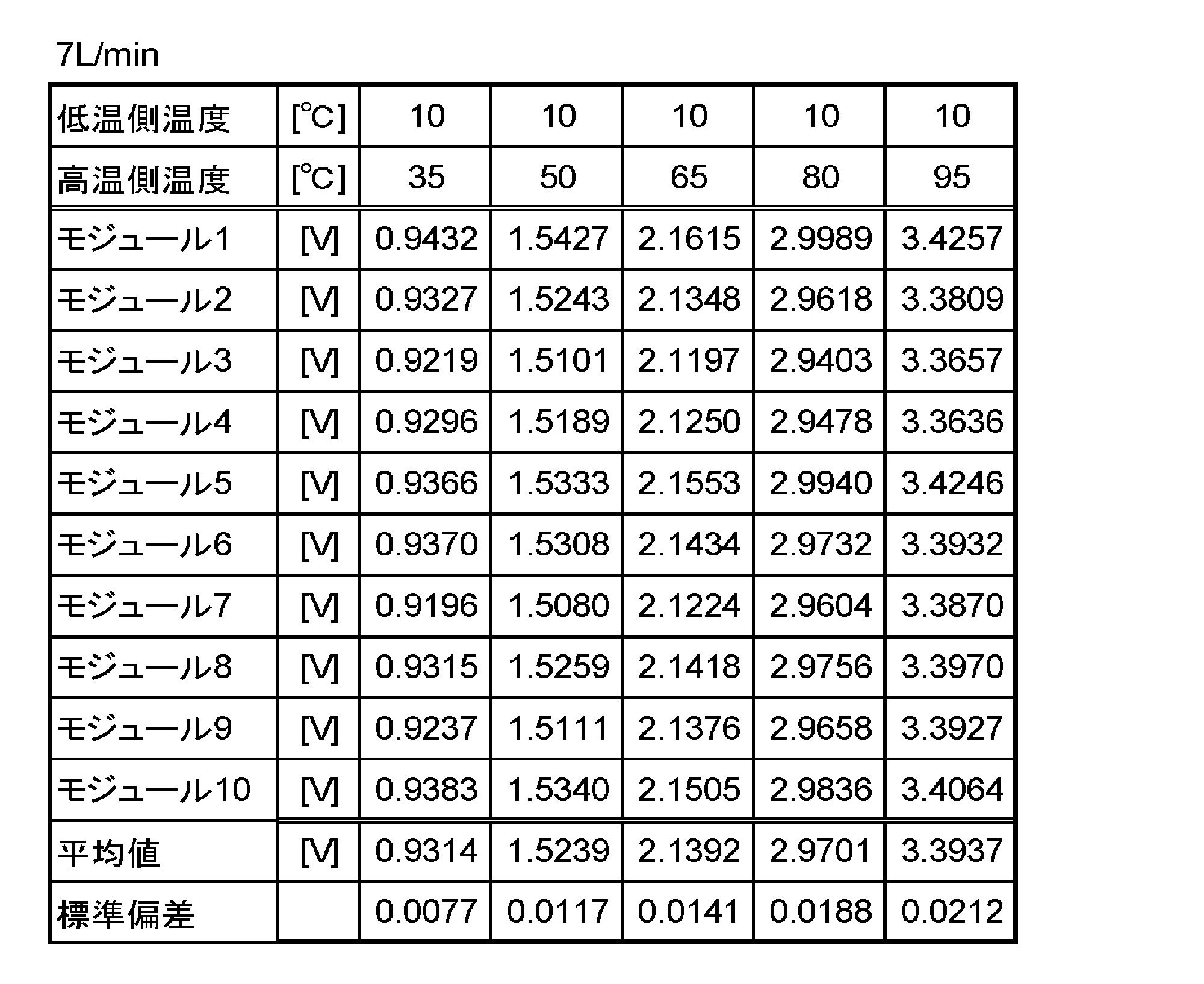
3つの表から明らかなように、各条件において、10個の熱電変換モジュール1~10の各々からほぼ同様な出力電圧(V)が得られていることがわかる。すなわち、各枠部材に冷水と温水が十分かつ均等に供給されて、各熱電変換モジュールの上面と下面が冷却または加熱されて発電が実際に起こっていることがわかる。また、流量が増加し、あるいは温水温度が上昇するにつれて、発電量が増え出力電圧(V)が増加していることがわかる。表3の7(L/min)の流量において、95℃の温水を用いた場合に平均で約3.4Vの出力電圧を得ることができることがわかった。
本発明の実施形態について、図を参照しながら説明をした。しかし、本発明はこれらの実施形態に限られるものではない。さらに、本発明はその趣旨を逸脱しない範囲で当業者の知識に基づき種々なる改良、修正、変形を加えた態様で実施できるものである。
本発明の熱電発電装置は、小型で拡張性の高い熱電発電装置として産業上幅広く利用することができる。
1 熱電変換モジュール
2、22、23、24 枠部材
3 ゴム製パッキン
4 上蓋(基板)
5 下蓋(基板)
6、7、20、21、20A、20B、21A、21B、50、60、61、62、63 流体供給部材
8、11、52、54 流体排出開口
9、10、51、53 流体注入開口
12、29 流体排出孔
13、30 流体注入孔
14、26、27 注入孔
15、25、28 排出孔
16 P型熱電変換素子
17 N型熱電変換素子
18 上側の電極
19 下側の電極
32 シール材
33 開口(貫通孔)
40、41、42、43、58、59 ネジ孔
44、45、56、57 ネジ
46 孔
47 ボルト
60 熱電変換モジュール
62 熱交換器
64 伝熱面
100 熱電発電装置
2、22、23、24 枠部材
3 ゴム製パッキン
4 上蓋(基板)
5 下蓋(基板)
6、7、20、21、20A、20B、21A、21B、50、60、61、62、63 流体供給部材
8、11、52、54 流体排出開口
9、10、51、53 流体注入開口
12、29 流体排出孔
13、30 流体注入孔
14、26、27 注入孔
15、25、28 排出孔
16 P型熱電変換素子
17 N型熱電変換素子
18 上側の電極
19 下側の電極
32 シール材
33 開口(貫通孔)
40、41、42、43、58、59 ネジ孔
44、45、56、57 ネジ
46 孔
47 ボルト
60 熱電変換モジュール
62 熱交換器
64 伝熱面
100 熱電発電装置
Claims (13)
- 複数の熱電変換モジュールの各々が開口部を有する枠部材に挟まれるようにして積層された積層体と、
積層体の異なる側面に沿って延びる少なくとも2つの流体供給部材と、を備え、
枠部材の各々は、一つ置きに異なる流体供給部材に面する側面に開口部に至る流体注入孔と流体排出孔を有し、
流体供給部材の各々は、その側面に沿って延びる流体注入開口及び流体排出開口の一方または双方を有し、各流体供給部材の側面には、対応する枠部材の側面の流体注入孔または流体排出孔に位置合わせされ、流体注入開口または流体排出開口に至る注入孔または排出孔が設けられ、
枠部材の側面の流体注入孔と流体排出孔の各々は、中央に流路となる開口を有する第1のシール材を介して、流体供給部材の側面の位置合わせされた注入孔と排出孔の各々に接合する、熱電発電装置。 - 前記流体供給部材は、前記積層体の2つの側面に沿って1つずつ配置され、前記流体供給部材の各々に前記流体注入開口及び流体排出開口が設けられ、一方の前記流体供給部材の前記流体注入開口には高温流体が供給され、他方の前記流体供給部材の前記流体注入開口には低温流体が供給される、請求項1に記載の熱電発電装置。
- 前記流体供給部材は、前記積層体の2つの側面に沿って2つずつ配置され、各側面の一方の前記流体供給部材には前記流体注入開口が設けられ、他方の前記流体供給部材には前記流体排出開口が設けられ、一方の側面の前記流体供給部材の前記流体注入開口には高温流体が供給され、他方の側面の前記流体供給部材の前記流体注入開口には低温流体が供給される、請求項1に記載の熱電発電装置。
- 前記流体供給部材は、前記積層体の4つの側面に沿って1つずつ配置され、対向する2つの前記流体供給部材の一方に前記流体注入開口がそれぞれ設けられ、他方の前記流体供給部材に前記流体排出開口がそれぞれ設けられ、前記流体供給部材の前記流体注入開口の一方には高温流体が供給され、他方の前記流体注入開口には低温流体が供給される、請求項1に記載の熱電発電装置。
- 前記熱電変換モジュールは、前記枠部材の開口部の外周に沿って設けられた第2のシール材を介して前記枠部材と接合する、請求項1に記載の熱電発電装置。
- 前記枠部材の側面の流体注入孔と流体排出孔の各々、及び前記流体供給部材の側面の注入孔と排出孔の各々は、前記第1のシール材の少なくとも端部が嵌まる凹部を有する、請求項1に記載の熱電発電装置。
- 前記第1のシール材は、球、円柱、ドーナツ形、または直方体のいずれかの形状を有する弾性体からなる、請求項6に記載の熱電発電装置。
- 前記熱電変換モジュールは、N型熱電変換素子とP型熱電変換素子が上下の電極間に直列に配置されたπ型の基本構造を有する、請求項1に記載の熱電発電装置。
- 複数の熱電変換モジュールの各々が開口部を有する枠部材に挟まれるようにして積層された積層体と、
積層体の1つの側面に沿って延びる1つの流体供給部材と、を備え、
枠部材の各々は、流体供給部材に面する側面に開口部に至る流体注入孔と流体排出孔を有し、枠部材の一つ置きに流体注入孔と流体排出孔が枠部材の側面の異なる位置にあり、
流体供給部材は、その側面に沿って延びる2組の流体注入開口及び流体排出開口を有し、流体供給部材の側面には、各枠部材の側面の流体注入孔と流体排出孔に位置合わせされ、対応する流体注入開口と流体排出開口に至る注入孔と排出孔が設けられ、
枠部材の側面の流体注入孔と流体排出孔の各々は、中央に流路となる開口を有する第1のシール材を介して、流体供給部材の側面の位置合わせされた注入孔と排出孔の各々に接合する、熱電発電装置。 - 前記熱電変換モジュールは、前記枠部材の開口部の外周に沿って設けられた第2のシール材を介して前記枠部材と接合する、請求項9に記載の熱電発電装置。
- 前記枠部材の側面の流体注入孔と流体排出孔の各々、及び前記流体供給部材の側面の注入孔と排出孔の各々は、前記第1のシール材の少なくとも端部が嵌まる凹部を有する、請求項9に記載の熱電発電装置。
- 前記第1のシール材は、球、円柱、ドーナツ形、または直方体のいずれかの形状を有する弾性体からなる、請求項11に記載の熱電発電装置。
- 前記熱電変換モジュールは、N型熱電変換素子とP型熱電変換素子が上下の電極間に直列に配置されたπ型の基本構造を有する、請求項9に記載の熱電発電装置。
Priority Applications (1)
| Application Number | Priority Date | Filing Date | Title |
|---|---|---|---|
| JP2019520221A JP6906250B2 (ja) | 2017-05-23 | 2018-05-18 | 熱電発電装置 |
Applications Claiming Priority (2)
| Application Number | Priority Date | Filing Date | Title |
|---|---|---|---|
| JP2017101686 | 2017-05-23 | ||
| JP2017-101686 | 2017-05-23 |
Publications (1)
| Publication Number | Publication Date |
|---|---|
| WO2018216624A1 true WO2018216624A1 (ja) | 2018-11-29 |
Family
ID=64396729
Family Applications (1)
| Application Number | Title | Priority Date | Filing Date |
|---|---|---|---|
| PCT/JP2018/019350 Ceased WO2018216624A1 (ja) | 2017-05-23 | 2018-05-18 | 熱電発電装置 |
Country Status (2)
| Country | Link |
|---|---|
| JP (1) | JP6906250B2 (ja) |
| WO (1) | WO2018216624A1 (ja) |
Cited By (1)
| Publication number | Priority date | Publication date | Assignee | Title |
|---|---|---|---|---|
| CN114678460A (zh) * | 2022-05-31 | 2022-06-28 | 四川大学 | 一种可分离式热电转换系统 |
Citations (5)
| Publication number | Priority date | Publication date | Assignee | Title |
|---|---|---|---|---|
| JP2005253217A (ja) * | 2004-03-04 | 2005-09-15 | Denso Corp | 熱電発電装置 |
| JP2015012172A (ja) * | 2013-06-28 | 2015-01-19 | 株式会社東芝 | 熱電発電装置 |
| JP2015165555A (ja) * | 2014-02-10 | 2015-09-17 | パナソニック株式会社 | 熱発電ユニット |
| US20150325767A1 (en) * | 2014-05-06 | 2015-11-12 | Mahle International Gmbh | Thermoelectric generator |
| JP2016017737A (ja) * | 2014-07-07 | 2016-02-01 | 現代自動車株式会社Hyundaimotor Company | Ted熱交換器 |
Family Cites Families (2)
| Publication number | Priority date | Publication date | Assignee | Title |
|---|---|---|---|---|
| JP5889584B2 (ja) * | 2010-09-10 | 2016-03-22 | 株式会社東芝 | 温度差発電装置及び熱電変換素子フレーム |
| JP2016019357A (ja) * | 2014-07-08 | 2016-02-01 | 学校法人文理学園 | 温度差発電装置、発電システム、及び、流路形成部材 |
-
2018
- 2018-05-18 WO PCT/JP2018/019350 patent/WO2018216624A1/ja not_active Ceased
- 2018-05-18 JP JP2019520221A patent/JP6906250B2/ja active Active
Patent Citations (5)
| Publication number | Priority date | Publication date | Assignee | Title |
|---|---|---|---|---|
| JP2005253217A (ja) * | 2004-03-04 | 2005-09-15 | Denso Corp | 熱電発電装置 |
| JP2015012172A (ja) * | 2013-06-28 | 2015-01-19 | 株式会社東芝 | 熱電発電装置 |
| JP2015165555A (ja) * | 2014-02-10 | 2015-09-17 | パナソニック株式会社 | 熱発電ユニット |
| US20150325767A1 (en) * | 2014-05-06 | 2015-11-12 | Mahle International Gmbh | Thermoelectric generator |
| JP2016017737A (ja) * | 2014-07-07 | 2016-02-01 | 現代自動車株式会社Hyundaimotor Company | Ted熱交換器 |
Cited By (1)
| Publication number | Priority date | Publication date | Assignee | Title |
|---|---|---|---|---|
| CN114678460A (zh) * | 2022-05-31 | 2022-06-28 | 四川大学 | 一种可分离式热电转换系统 |
Also Published As
| Publication number | Publication date |
|---|---|
| JP6906250B2 (ja) | 2021-07-21 |
| JPWO2018216624A1 (ja) | 2020-05-21 |
Similar Documents
| Publication | Publication Date | Title |
|---|---|---|
| US20130213449A1 (en) | Thermoelectric plate and frame exchanger | |
| CN108431541B (zh) | 分段式适形热交换器 | |
| CN104103871B (zh) | 蓄电模块、蓄电装置及风路连接构件 | |
| US9755132B2 (en) | Thermoelectric generation unit and thermoelectric generation system | |
| WO2009041020A1 (ja) | 熱電発電装置及び該熱電発電装置を用いた発電システム | |
| RU2142178C1 (ru) | Устройство для нагрева и охлаждения жидкости | |
| JP5268605B2 (ja) | 熱電変換装置、熱電発電システム、および熱電発電方法 | |
| JP6906250B2 (ja) | 熱電発電装置 | |
| CN103178753B (zh) | 车辆的热电发电机 | |
| JP4785476B2 (ja) | 熱電発電構造及び発電機能付き熱交換器 | |
| CN110165941A (zh) | 一种防水耐压型温差发电装置 | |
| US9368708B2 (en) | Thermoelectric generation unit and thermoelectric generation system | |
| JP6456160B2 (ja) | 熱発電ユニットおよび熱発電システム | |
| EP2960953B1 (en) | Plate heat exchanger assembly and a frame to be used in such assembly | |
| US10873018B2 (en) | Thermoelectric generator system | |
| CN110419114B (zh) | 热电发电装置 | |
| KR102029098B1 (ko) | 배기관에 설치되는 열전발전시스템 | |
| CN107431119A (zh) | 能量回收组件及其提供方法 | |
| JP2015012172A (ja) | 熱電発電装置 | |
| CN111989790B (zh) | 热电发电装置 | |
| KR20250062621A (ko) | 폐열을 재활용하여 전기에너지를 생산하는 양방향 열전발전 파워모듈 및 그 파워모듈을 구비하는 열전발전장치 | |
| TWI856909B (zh) | 模組式熱電發電裝置 | |
| SE2100039A1 (en) | Plate Heat Exchanger Thermoelectric Generator | |
| KR20250117917A (ko) | 수냉블럭과 일체화된 열전반도체모듈 및 그 열전반도체모듈을 포함하는 열전냉각유닛 | |
| JP2016063075A (ja) | 熱発電ユニット、熱発電システムおよび熱発電モジュール |
Legal Events
| Date | Code | Title | Description |
|---|---|---|---|
| 121 | Ep: the epo has been informed by wipo that ep was designated in this application |
Ref document number: 18806743 Country of ref document: EP Kind code of ref document: A1 |
|
| ENP | Entry into the national phase |
Ref document number: 2019520221 Country of ref document: JP Kind code of ref document: A |
|
| NENP | Non-entry into the national phase |
Ref country code: DE |
|
| 122 | Ep: pct application non-entry in european phase |
Ref document number: 18806743 Country of ref document: EP Kind code of ref document: A1 |