WO2018216596A1 - Catheter - Google Patents
Catheter Download PDFInfo
- Publication number
- WO2018216596A1 WO2018216596A1 PCT/JP2018/019113 JP2018019113W WO2018216596A1 WO 2018216596 A1 WO2018216596 A1 WO 2018216596A1 JP 2018019113 W JP2018019113 W JP 2018019113W WO 2018216596 A1 WO2018216596 A1 WO 2018216596A1
- Authority
- WO
- WIPO (PCT)
- Prior art keywords
- length region
- tubular
- region
- catheter
- tubular body
- Prior art date
Links
- 229920005989 resin Polymers 0.000 claims abstract description 92
- 239000011347 resin Substances 0.000 claims abstract description 92
- 238000005304 joining Methods 0.000 claims description 77
- 230000007423 decrease Effects 0.000 claims description 9
- 239000010410 layer Substances 0.000 description 128
- 235000019589 hardness Nutrition 0.000 description 81
- 239000000463 material Substances 0.000 description 65
- 230000003014 reinforcing effect Effects 0.000 description 57
- 230000008859 change Effects 0.000 description 39
- 210000004204 blood vessel Anatomy 0.000 description 30
- -1 polytetrafluoroethylene Polymers 0.000 description 16
- 238000005452 bending Methods 0.000 description 13
- 239000004642 Polyimide Substances 0.000 description 12
- 229920001721 polyimide Polymers 0.000 description 12
- 239000002861 polymer material Substances 0.000 description 12
- 229920001343 polytetrafluoroethylene Polymers 0.000 description 12
- 239000004810 polytetrafluoroethylene Substances 0.000 description 12
- 229920001169 thermoplastic Polymers 0.000 description 12
- 238000004804 winding Methods 0.000 description 12
- 230000004048 modification Effects 0.000 description 11
- 238000012986 modification Methods 0.000 description 11
- 239000000243 solution Substances 0.000 description 10
- 239000002033 PVDF binder Substances 0.000 description 8
- 239000004696 Poly ether ether ketone Substances 0.000 description 8
- 229920001971 elastomer Polymers 0.000 description 8
- 239000000806 elastomer Substances 0.000 description 8
- 229920002530 polyetherether ketone Polymers 0.000 description 8
- 229920000139 polyethylene terephthalate Polymers 0.000 description 8
- 239000005020 polyethylene terephthalate Substances 0.000 description 8
- 229920002981 polyvinylidene fluoride Polymers 0.000 description 8
- 229910001220 stainless steel Inorganic materials 0.000 description 8
- 238000004519 manufacturing process Methods 0.000 description 7
- YCKRFDGAMUMZLT-UHFFFAOYSA-N Fluorine atom Chemical compound [F] YCKRFDGAMUMZLT-UHFFFAOYSA-N 0.000 description 6
- 239000004952 Polyamide Substances 0.000 description 6
- 239000002872 contrast media Substances 0.000 description 6
- 239000003814 drug Substances 0.000 description 6
- 229940079593 drug Drugs 0.000 description 6
- 229910052731 fluorine Inorganic materials 0.000 description 6
- 239000011737 fluorine Substances 0.000 description 6
- 229920002647 polyamide Polymers 0.000 description 6
- 230000002787 reinforcement Effects 0.000 description 6
- 239000010935 stainless steel Substances 0.000 description 6
- 239000000126 substance Substances 0.000 description 6
- WFKWXMTUELFFGS-UHFFFAOYSA-N tungsten Chemical compound [W] WFKWXMTUELFFGS-UHFFFAOYSA-N 0.000 description 6
- 229910052721 tungsten Inorganic materials 0.000 description 6
- 239000010937 tungsten Substances 0.000 description 6
- 239000011162 core material Substances 0.000 description 5
- 238000000034 method Methods 0.000 description 5
- RYGMFSIKBFXOCR-UHFFFAOYSA-N Copper Chemical compound [Cu] RYGMFSIKBFXOCR-UHFFFAOYSA-N 0.000 description 4
- 229910000881 Cu alloy Inorganic materials 0.000 description 4
- 239000004677 Nylon Substances 0.000 description 4
- 229920002614 Polyether block amide Polymers 0.000 description 4
- 239000004698 Polyethylene Substances 0.000 description 4
- 239000004734 Polyphenylene sulfide Substances 0.000 description 4
- 239000004743 Polypropylene Substances 0.000 description 4
- 229910000831 Steel Inorganic materials 0.000 description 4
- 229910001069 Ti alloy Inorganic materials 0.000 description 4
- RTAQQCXQSZGOHL-UHFFFAOYSA-N Titanium Chemical compound [Ti] RTAQQCXQSZGOHL-UHFFFAOYSA-N 0.000 description 4
- TZCXTZWJZNENPQ-UHFFFAOYSA-L barium sulfate Chemical compound [Ba+2].[O-]S([O-])(=O)=O TZCXTZWJZNENPQ-UHFFFAOYSA-L 0.000 description 4
- 239000010949 copper Substances 0.000 description 4
- 229910052802 copper Inorganic materials 0.000 description 4
- 238000010586 diagram Methods 0.000 description 4
- JJJFUHOGVZWXNQ-UHFFFAOYSA-N enbucrilate Chemical compound CCCCOC(=O)C(=C)C#N JJJFUHOGVZWXNQ-UHFFFAOYSA-N 0.000 description 4
- 229950010048 enbucrilate Drugs 0.000 description 4
- 239000005038 ethylene vinyl acetate Substances 0.000 description 4
- 229920001903 high density polyethylene Polymers 0.000 description 4
- 239000004700 high-density polyethylene Substances 0.000 description 4
- 239000011256 inorganic filler Substances 0.000 description 4
- 229910003475 inorganic filler Inorganic materials 0.000 description 4
- 239000007769 metal material Substances 0.000 description 4
- 229920001778 nylon Polymers 0.000 description 4
- 230000002093 peripheral effect Effects 0.000 description 4
- 229920001200 poly(ethylene-vinyl acetate) Polymers 0.000 description 4
- 229920002312 polyamide-imide Polymers 0.000 description 4
- 229920001707 polybutylene terephthalate Polymers 0.000 description 4
- 229920000573 polyethylene Polymers 0.000 description 4
- 229920000069 polyphenylene sulfide Polymers 0.000 description 4
- 229920001155 polypropylene Polymers 0.000 description 4
- 239000010959 steel Substances 0.000 description 4
- 239000010936 titanium Substances 0.000 description 4
- 229910052719 titanium Inorganic materials 0.000 description 4
- 238000010438 heat treatment Methods 0.000 description 3
- 230000008569 process Effects 0.000 description 3
- QNRATNLHPGXHMA-XZHTYLCXSA-N (r)-(6-ethoxyquinolin-4-yl)-[(2s,4s,5r)-5-ethyl-1-azabicyclo[2.2.2]octan-2-yl]methanol;hydrochloride Chemical compound Cl.C([C@H]([C@H](C1)CC)C2)CN1[C@@H]2[C@H](O)C1=CC=NC2=CC=C(OCC)C=C21 QNRATNLHPGXHMA-XZHTYLCXSA-N 0.000 description 2
- 229910000014 Bismuth subcarbonate Inorganic materials 0.000 description 2
- ZOXJGFHDIHLPTG-UHFFFAOYSA-N Boron Chemical compound [B] ZOXJGFHDIHLPTG-UHFFFAOYSA-N 0.000 description 2
- 229910001209 Low-carbon steel Inorganic materials 0.000 description 2
- 229920001774 Perfluoroether Polymers 0.000 description 2
- 229910000639 Spring steel Inorganic materials 0.000 description 2
- 239000000853 adhesive Substances 0.000 description 2
- 230000001070 adhesive effect Effects 0.000 description 2
- 239000002246 antineoplastic agent Substances 0.000 description 2
- 239000011324 bead Substances 0.000 description 2
- MGLUJXPJRXTKJM-UHFFFAOYSA-L bismuth subcarbonate Chemical compound O=[Bi]OC(=O)O[Bi]=O MGLUJXPJRXTKJM-UHFFFAOYSA-L 0.000 description 2
- 229940036358 bismuth subcarbonate Drugs 0.000 description 2
- 229910052796 boron Inorganic materials 0.000 description 2
- DQXBYHZEEUGOBF-UHFFFAOYSA-N but-3-enoic acid;ethene Chemical compound C=C.OC(=O)CC=C DQXBYHZEEUGOBF-UHFFFAOYSA-N 0.000 description 2
- 238000004891 communication Methods 0.000 description 2
- 229920001577 copolymer Polymers 0.000 description 2
- 230000007797 corrosion Effects 0.000 description 2
- 238000005260 corrosion Methods 0.000 description 2
- 238000004132 cross linking Methods 0.000 description 2
- 238000001125 extrusion Methods 0.000 description 2
- 239000000835 fiber Substances 0.000 description 2
- 239000000945 filler Substances 0.000 description 2
- 238000010030 laminating Methods 0.000 description 2
- 239000007788 liquid Substances 0.000 description 2
- 230000007246 mechanism Effects 0.000 description 2
- 229910052751 metal Inorganic materials 0.000 description 2
- 239000002184 metal Substances 0.000 description 2
- 229910001000 nickel titanium Inorganic materials 0.000 description 2
- 230000000149 penetrating effect Effects 0.000 description 2
- 239000002504 physiological saline solution Substances 0.000 description 2
- 229920005594 polymer fiber Polymers 0.000 description 2
- 239000002952 polymeric resin Substances 0.000 description 2
- 239000004814 polyurethane Substances 0.000 description 2
- 239000004800 polyvinyl chloride Substances 0.000 description 2
- 239000011241 protective layer Substances 0.000 description 2
- 239000002356 single layer Substances 0.000 description 2
- BFKJFAAPBSQJPD-UHFFFAOYSA-N tetrafluoroethene Chemical group FC(F)=C(F)F BFKJFAAPBSQJPD-UHFFFAOYSA-N 0.000 description 2
- 230000002792 vascular Effects 0.000 description 2
- 208000005392 Spasm Diseases 0.000 description 1
- 238000006073 displacement reaction Methods 0.000 description 1
- 230000000877 morphologic effect Effects 0.000 description 1
- 238000003825 pressing Methods 0.000 description 1
Images


Classifications
-
- A—HUMAN NECESSITIES
- A61—MEDICAL OR VETERINARY SCIENCE; HYGIENE
- A61M—DEVICES FOR INTRODUCING MEDIA INTO, OR ONTO, THE BODY; DEVICES FOR TRANSDUCING BODY MEDIA OR FOR TAKING MEDIA FROM THE BODY; DEVICES FOR PRODUCING OR ENDING SLEEP OR STUPOR
- A61M25/00—Catheters; Hollow probes
-
- A—HUMAN NECESSITIES
- A61—MEDICAL OR VETERINARY SCIENCE; HYGIENE
- A61M—DEVICES FOR INTRODUCING MEDIA INTO, OR ONTO, THE BODY; DEVICES FOR TRANSDUCING BODY MEDIA OR FOR TAKING MEDIA FROM THE BODY; DEVICES FOR PRODUCING OR ENDING SLEEP OR STUPOR
- A61M25/00—Catheters; Hollow probes
- A61M25/0067—Catheters; Hollow probes characterised by the distal end, e.g. tips
- A61M25/0068—Static characteristics of the catheter tip, e.g. shape, atraumatic tip, curved tip or tip structure
- A61M25/0069—Tip not integral with tube
-
- A—HUMAN NECESSITIES
- A61—MEDICAL OR VETERINARY SCIENCE; HYGIENE
- A61M—DEVICES FOR INTRODUCING MEDIA INTO, OR ONTO, THE BODY; DEVICES FOR TRANSDUCING BODY MEDIA OR FOR TAKING MEDIA FROM THE BODY; DEVICES FOR PRODUCING OR ENDING SLEEP OR STUPOR
- A61M25/00—Catheters; Hollow probes
- A61M25/0009—Making of catheters or other medical or surgical tubes
- A61M25/001—Forming the tip of a catheter, e.g. bevelling process, join or taper
-
- A—HUMAN NECESSITIES
- A61—MEDICAL OR VETERINARY SCIENCE; HYGIENE
- A61M—DEVICES FOR INTRODUCING MEDIA INTO, OR ONTO, THE BODY; DEVICES FOR TRANSDUCING BODY MEDIA OR FOR TAKING MEDIA FROM THE BODY; DEVICES FOR PRODUCING OR ENDING SLEEP OR STUPOR
- A61M25/00—Catheters; Hollow probes
- A61M25/0043—Catheters; Hollow probes characterised by structural features
- A61M25/0045—Catheters; Hollow probes characterised by structural features multi-layered, e.g. coated
-
- A—HUMAN NECESSITIES
- A61—MEDICAL OR VETERINARY SCIENCE; HYGIENE
- A61M—DEVICES FOR INTRODUCING MEDIA INTO, OR ONTO, THE BODY; DEVICES FOR TRANSDUCING BODY MEDIA OR FOR TAKING MEDIA FROM THE BODY; DEVICES FOR PRODUCING OR ENDING SLEEP OR STUPOR
- A61M25/00—Catheters; Hollow probes
- A61M25/0043—Catheters; Hollow probes characterised by structural features
- A61M25/005—Catheters; Hollow probes characterised by structural features with embedded materials for reinforcement, e.g. wires, coils, braids
- A61M25/0052—Localized reinforcement, e.g. where only a specific part of the catheter is reinforced, for rapid exchange guidewire port
-
- A—HUMAN NECESSITIES
- A61—MEDICAL OR VETERINARY SCIENCE; HYGIENE
- A61M—DEVICES FOR INTRODUCING MEDIA INTO, OR ONTO, THE BODY; DEVICES FOR TRANSDUCING BODY MEDIA OR FOR TAKING MEDIA FROM THE BODY; DEVICES FOR PRODUCING OR ENDING SLEEP OR STUPOR
- A61M25/00—Catheters; Hollow probes
- A61M25/0043—Catheters; Hollow probes characterised by structural features
- A61M25/005—Catheters; Hollow probes characterised by structural features with embedded materials for reinforcement, e.g. wires, coils, braids
- A61M25/0053—Catheters; Hollow probes characterised by structural features with embedded materials for reinforcement, e.g. wires, coils, braids having a variable stiffness along the longitudinal axis, e.g. by varying the pitch of the coil or braid
-
- A—HUMAN NECESSITIES
- A61—MEDICAL OR VETERINARY SCIENCE; HYGIENE
- A61M—DEVICES FOR INTRODUCING MEDIA INTO, OR ONTO, THE BODY; DEVICES FOR TRANSDUCING BODY MEDIA OR FOR TAKING MEDIA FROM THE BODY; DEVICES FOR PRODUCING OR ENDING SLEEP OR STUPOR
- A61M25/00—Catheters; Hollow probes
- A61M25/0043—Catheters; Hollow probes characterised by structural features
- A61M25/0054—Catheters; Hollow probes characterised by structural features with regions for increasing flexibility
-
- A—HUMAN NECESSITIES
- A61—MEDICAL OR VETERINARY SCIENCE; HYGIENE
- A61M—DEVICES FOR INTRODUCING MEDIA INTO, OR ONTO, THE BODY; DEVICES FOR TRANSDUCING BODY MEDIA OR FOR TAKING MEDIA FROM THE BODY; DEVICES FOR PRODUCING OR ENDING SLEEP OR STUPOR
- A61M25/00—Catheters; Hollow probes
- A61M25/0097—Catheters; Hollow probes characterised by the hub
-
- A—HUMAN NECESSITIES
- A61—MEDICAL OR VETERINARY SCIENCE; HYGIENE
- A61M—DEVICES FOR INTRODUCING MEDIA INTO, OR ONTO, THE BODY; DEVICES FOR TRANSDUCING BODY MEDIA OR FOR TAKING MEDIA FROM THE BODY; DEVICES FOR PRODUCING OR ENDING SLEEP OR STUPOR
- A61M5/00—Devices for bringing media into the body in a subcutaneous, intra-vascular or intramuscular way; Accessories therefor, e.g. filling or cleaning devices, arm-rests
- A61M5/178—Syringes
Definitions
- the present invention relates to a catheter.
- the catheter has a flexibility that does not apply an excessive load to the body tissue when inserted into a body cavity such as a blood vessel, and at the same time, is suitable for obtaining good running performance, blood vessel selectivity, and torque characteristics of the catheter. It is hoped to have.
- koshi refers to the characteristics of the portion (main body) inserted into the body cavity of the catheter determined by elasticity, hardness, flexibility, and the like. If the stiffness of the catheter is suitable, the catheter can move in the body cavity following the operation of the operator.
- Patent Document 1 describes that the hardness of the outer layer of the catheter is gradually reduced from the proximal end portion to the distal end portion of the catheter.
- the catheter described in Patent Document 1 is a tube having a main body having an inner layer, an outer layer, and an intermediate layer provided between the inner layer and the outer layer.
- the tube has a tapered portion whose diameter continuously increases from the distal end to the proximal end.
- the taper-shaped portion of the catheter main body is made to go to the distal end portion in such a manner that the hardness of the resin as a material is gradually reduced toward the distal end portion and the diameter is reduced. It is described that the rigidity of the catheter body is reduced.
- the rigidity of the catheter body when the rigidity of the catheter body is changed along the axial direction of the tube, materials having different hardnesses are switched in the axial direction, or the rigidity caused by the tubular form of the tube is changed.
- the rigidity of the catheter body varies depending on the material switching position and the tubular shape of the tube, but the variation in the material switching position is a variation in the rigidity of the catheter, and thus functions such as vessel selectivity, vessel progression, and torque. appear. For this reason, in order to control the function of the catheter body, it is desirable to suppress variations in the material switching position for each catheter.
- Patent Document 1 does not describe any configuration for suppressing the variation of the material switching position for each product.
- Patent Document 1 described above does not describe any configuration for improving the kink resistance of the catheter body.
- the present invention has been made in view of the above points, and is excellent in manufacturing stability by suppressing the variation of the switching position while switching the hardness of the material in the axial direction.
- An object of the present invention is to provide a catheter with little variation in function.
- the present invention has been made in view of the above points, and provides a catheter capable of preventing the occurrence of kinks due to hardness discontinuity while switching the hardness of the material in the axial direction. With the goal.
- the catheter includes a resin tubular body having a changing portion in which the rigidity due to the tubular shape in the axial direction continuously decreases from the proximal end side toward the distal end side, A first length region and a second length region distal to the first length region in the tubular body on the distal side are defined, and the first length region is more than the resin hardness of the first length region.
- a catheter is provided that has a low resin hardness in the two-length region.
- a catheter having a tubular body, the tubular body being adjacent to the first length region and the first length region, and further to the distal side than the first length region.
- the second length region is defined, the resin hardness of the second length region is lower than the resin hardness of the first length region, and the first length region and the second length region are joined.
- the catheter is characterized in that the line has a non-uniform distance from a plane perpendicular to the axial direction of the tubular body.
- the present invention it is possible to provide a catheter that is excellent in manufacturing stability by suppressing the variation in switching position while switching the rigidity in the axial direction, and has little variation in functions such as blood vessel selectivity, blood vessel running property, and torque property. . Further, according to the present invention, it is possible to provide a catheter capable of preventing the occurrence of kinks due to rigidity discontinuity while switching the rigidity in the axial direction.
- FIG. 1st embodiment of this invention and 2nd embodiment It is a figure for demonstrating the catheter of 1st embodiment of this invention and 2nd embodiment. It is a cross-sectional view of FIG. It is a longitudinal cross-sectional view of FIG. It is the typical longitudinal cross-sectional view which expanded and showed the predetermined range containing the front-end
- FIG. 8 It is the perspective view which showed the part of the change part of the tubular main body shown in FIG. 8, Comprising: It is the figure which showed the joining line in a change part. It is a figure for demonstrating the circumferential direction of the tubular main body in the catheter of 2nd embodiment of this invention, and the position of a joining line.
- FIG. 2 is a cross-sectional view of the catheter 1 along the arrow II-II shown in FIG.
- FIG. 3 is a longitudinal sectional view of the catheter 1 along the arrow III-III shown in FIG.
- the catheter 1 of the present embodiment is an active catheter in which an operation line 60 is disposed inside the tubular body 10 and the distal end T of the tubular body 10 is bent by operating the operation unit 90 and the bending operation unit 92. is there.
- the catheter of the present invention is not limited to this, and may be an inactive catheter that does not include the operation line 60 or the operation unit 90.
- the catheter 1 of the present embodiment has an operation unit 90 provided at the proximal end of the tubular main body 10.
- the end opposite to the side where the tubular main body 10 is connected to the operation unit 90 is referred to as a tip T.
- the operation unit 90 constitutes an operation mechanism for performing a bending operation of the distal portion DE of the tubular main body 10 together with the operation line 60 (see FIGS. 2 and 3).
- the operation unit 90 of the present embodiment includes a main body case 94 that is held by an operator with a hand, and a bending operation unit 92 that is provided to be rotatable with respect to the main body case 94.
- the proximal end of the tubular main body 10 is introduced into the main body case 94.
- a concave portion 95 is formed in the main body case 94 at a position in contact with the bending operation portion 92.
- the concave portion 95 is provided with a slider 98 that slides forward and backward toward the bending operation portion 92.
- the operation unit 90 includes a hub 96 provided in communication with the main lumen 20 of the tubular main body 10.
- a syringe (not shown) is attached to the hub 96.
- the hub 96 is provided at the rear end of the main body case 94, and a syringe is attached from the rear of the hub 96.
- the chemical solution examples include a contrast agent, a liquid anticancer agent, physiological saline, a chemical solution such as NBCA (n-butyl-2-cyanoacrylate) used as an instantaneous adhesive, a detachable coil, a bead (emboli globular substance), and the like. Mention may be made of medical devices.
- NBCA n-butyl-2-cyanoacrylate
- the tubular main body 10 shown in FIG. 1 is also called a sheath, and is a hollow tubular and long member in which a main lumen (main lumen) 20 is formed. More specifically, the tubular main body 10 is formed to have an outer diameter that allows entry into the blood vessel.
- the tubular body 10 is a resin having a “change part” in which the rigidity caused by the tubular shape continuously decreases from the proximal end side toward the distal end side in the axial direction (the axis passing through the central point of the cross section of the main lumen 20).
- a tubular body made of Here, the “rigidity resulting from the tubular form” is the rigidity resulting from the inner diameter or outer diameter of the tubular body 10 and the wall thickness of the tubular body 10.
- the “tubular form” includes at least one of the thickness, outer diameter, and inner diameter of the tubular body as an element.
- the rigidity resulting from the form of the tubular body 10 is small when the inner diameter or the outer diameter of the tubular body 10 is relatively thin, and is large when it is thick. Further, the tubular body 10 is larger if the wall thickness is relatively thick, and smaller if it is thin.
- the tubular body 10 is tubular without changing the outer diameter of the main lumen 20 from the distal end toward the proximal end.
- the main body 10 has a tapered shape in which the outer diameter continuously increases (thickness increases). If it does in this way, the rigidity resulting from the form of the tubular main body 10 will increase continuously from the front end T toward the base end.
- the tubular body 10 includes a first length region a1 (see FIG. 4) in the tubular body distal to the change portion, and a second length region located distal to the first length region. a2 (see FIG. 4) is defined.
- the resin hardness of the second length region is lower than the resin hardness of the first length region. That is, in the present embodiment, the tubular body 10 has a first length region in a predetermined length range distal to the tapered portion (tip T side). Furthermore, a range of a predetermined length further on the distal side than the first length region is set as the second length region.
- the first length region a1 and the second length region a2 will be described in detail later.
- the tubular body 10 according to the present invention is not limited to the following laminated configuration.
- the tubular body 10 has a laminated structure.
- the tubular main body 10 is configured by laminating an inner layer (main tube) 24 and an outer layer 50 in order from the inner diameter side with the main lumen 20 as the center.
- a hydrophilic layer (not shown) is formed on the outer surface of the outer layer 50.
- the inner layer 24 and the outer layer 50 are formed of a flexible resin material, and each has a tubular shape and a substantially uniform thickness in the circumferential direction.
- the inner layer 24 is the innermost layer of the tubular body 10 and defines the main lumen 20 by the inner wall surface thereof.
- the shape of the cross section of the main lumen 20 is not particularly limited, but is circular in this embodiment.
- the term “cross section of the main lumen” refers to a cross section of a shape defined by the outer peripheral surface of the main lumen 20 (a long cylinder in the axial direction of the main lumen 20).
- the diameter of the cross section of the tubular body 10 is circular, and the diameter of the tubular body 10 differs depending on the position in the longitudinal direction (the axial direction of the main lumen 20). In a part or the entire length region, the diameter of the tubular body 10 is continuously increased from the distal end toward the proximal end.
- Examples of the material of the inner layer 24 include a fluorine-based thermoplastic polymer resin.
- Specific examples of the fluorine-based thermoplastic polymer material include polytetrafluoroethylene (PTFE), polyvinylidene fluoride (PVDF), and perfluoroalkoxy fluororesin (PFA).
- PTFE polytetrafluoroethylene
- PVDF polyvinylidene fluoride
- PFA perfluoroalkoxy fluororesin
- the wire reinforcement layer 30 is a protective layer that is provided on the inner diameter side of the operation line 60 in the tubular body 10 and protects the inner layer 24.
- the presence of the wire reinforcement layer 30 on the inner diameter side of the operation line 60 can prevent the operation line 60 from penetrating from the outer layer 50 to the inner layer 24 and exposed to the main lumen 20.
- the wire reinforcing layer 30 is formed by winding a reinforcing wire 32.
- the material of the reinforcing wire 32 includes a metal material such as tungsten (W), stainless steel (SUS), nickel titanium alloy, steel, titanium, copper, titanium alloy, or copper alloy, and is sheared more than the inner layer 24 and the outer layer 50.
- a resin material such as polyimide (PI), polyamideimide (PAI), or polyethylene terephthalate (PET) having high strength can be used.
- a fine stainless steel wire is used as the reinforcing wire 32.
- the number of strips and the number of meshes of the reinforcing wire 32 are not particularly limited.
- the number of meshes of the wire reinforcing layer 30 refers to the number of intersections (number of eyes) per unit length (1 inch) viewed in the extending direction of the reinforcing wires.
- the reinforcing wire 32 is wound obliquely around the inner layer 24.
- An angle formed by the extending direction of the reinforcing wire 32 with respect to the circumferential direction around the inner layer 24 is referred to as a pitch angle of the reinforcing wire 32.
- the pitch angle becomes a small angle.
- the pitch angle is a large angle close to 90 degrees.
- the pitch angle of the reinforcing wire 32 of the present embodiment is not particularly limited, but can be 30 degrees or more, preferably 45 degrees or more and 75 degrees or less.
- the number of reinforcing wires 32 constituting the wire reinforcing layer 30 is not particularly limited, but in this embodiment, the wire reinforcing layer 30 formed by 16 reinforcing wires 32 is illustrated.
- the subtube 40 is a hollow tubular member that defines a secondary lumen.
- the subtube 40 is embedded in the outer layer 50.
- the subtube 40 can be made of, for example, a thermoplastic polymer material.
- the thermoplastic polymer material include low friction resin materials such as polytetrafluoroethylene (PTFE), polyetheretherketone (PEEK), or tetrafluoroethylene / hexafluoropropylene copolymer (FEP).
- the subtube 40 is made of a material having a higher bending rigidity and tensile elastic modulus than the outer layer 50.
- the two sub tubes 40 are arranged on the same circumference so as to surround the main lumen 20.
- the catheter 1 of the present embodiment is an active type, and includes the sub-tube 40 and the holding wire 70 in addition to the operation line 60 and the operation unit 90. However, such a configuration is not necessary when the catheter of the present embodiment is an inactive type.
- the operation line 60 is loosely inserted in the sub tube 40 so as to be slidable.
- the distal end of the operation line 60 is fixed to the distal portion DE of the tubular body 10.
- a tensile force is applied to a position eccentric with respect to the axis of the tubular body 10, so that the tubular body 10 bends.
- the operation wire 60 may be formed of a single wire, but may be a stranded wire formed by twisting a plurality of thin wires.
- the number of fine wires constituting one stranded wire of the operation wire 60 is not particularly limited, but is preferably 3 or more.
- the operation wire 60 a low carbon steel (piano wire), stainless steel (SUS), a steel wire coated with corrosion resistance, titanium or a titanium alloy, or a metal wire such as tungsten can be used.
- the operation line 60 includes polyvinylidene fluoride (PVDF), high density polyethylene (HDPE), poly (paraphenylenebenzobisoxazole) (PBO), polyetheretherketone (PEEK), polyphenylene sulfide (PPS), Polymer fibers such as polybutylene terephthalate (PBT), polyimide (PI), polytetrafluoroethylene (PTFE), or boron fiber can be used.
- PVDF polyvinylidene fluoride
- HDPE high density polyethylene
- PBO poly (paraphenylenebenzobisoxazole)
- PEEK polyetheretherketone
- PPS polyphenylene sulfide
- Polymer fibers such as polybutylene terephthalate (PBT), polyimide (PI
- the holding wire 70 is wound in a spiral shape so as to surround the outside of the pair of sub-tubes 40 that are opposed to each other around the main lumen 20.
- the winding shape of the holding wire 70 of the present embodiment is a substantially elliptical shape or a substantially rhombic shape in which the arrangement direction of the subtubes 40 is the major axis direction.
- FIG. 3 the holding wire 70 whose winding shape forms a substantially rhombus is illustrated by a broken line.
- the holding wire 70 is in contact with the peripheral surface of the subtube 40, specifically, the outer surface that is opposite to the axis of the main lumen 20.
- the approximate rhombus means that the first diagonal line is longer than the second diagonal line, and the first diagonal line and the second diagonal line are substantially orthogonal.
- the approximate rhombus mentioned here includes a rhombus, a flat polygon such as a kite shape, a flat hexagon, and a flat octagon.
- the substantially elliptical shape includes an elliptical shape such as an oval shape as well as an elliptical shape or an oval shape.
- the cross-sectional shape of the main lumen 20 is circular, and is arranged at the center of the tubular main body 10, and the two sub tubes 40 are arranged 180 degrees opposite to each other around the main lumen 20.
- the shape of the cross section of the main lumen 20 is not limited to a circle, and may be another shape such as an ellipse or a rectangle.
- the sub-tubes 40 may be equally distributed around the main lumen 20 of three or more (N).
- the winding shape of the holding wire 70 may be a rounded N-square shape with each subtube 40 as a corner.
- the holding wire 70 As the material of the holding wire 70, any of the above metal materials or resin materials that can be used as the reinforcing wire 32 can be used.
- the holding wire 70 is formed to include a material different from the reinforcing wire 32.
- the ductility of the holding wire 70 is preferably higher than the ductility of the reinforcing wire 32.
- austenitic soft stainless steel (W1 or W2) which is a dull material, or copper or copper alloy is used for the holding wire 70, while tungsten or stainless spring steel can be used for the reinforcing wire 32.
- the outer layer 50 is a tubular portion that constitutes the main wall thickness of the tubular body 10. Inside the outer layer 50, a wire reinforcing layer 30, a sub tube 40, and a holding wire 70 are provided in this order from the inner diameter side. The wire reinforcing layer 30 and the holding wire 70 are arranged coaxially with the tubular main body 10.
- the difference in resin hardness between the first length region and the second length region of the tubular body 10 means that the resin hardness of the outer layer 50 constituting the main thickness of the tubular body 10 is different.
- the outer layer 50 may be a single layer or a multilayer, and when the outer layer 50 is a multilayer, it indicates that the resin hardness of the first length region and the second length region are different for the thickest layer of the plurality of layers. .
- thermoplastic polymer material As the material of the outer layer 50 , a thermoplastic polymer material can be used. As this thermoplastic polymer material, polyimide (PI), polyamideimide (PAI), polyethylene terephthalate (PET), polyethylene (PE), polyamide (PA), polyamide elastomer (PAE), polyether block amide (PEBA), etc. Mention may be made of nylon elastomers, polyurethane (PU), ethylene-vinyl acetate resin (EVA), polyvinyl chloride (PVC) or polypropylene (PP).
- the outer layer 50 may be mixed with an inorganic filler. Examples of the inorganic filler include contrast agents such as barium sulfate and bismuth subcarbonate.
- the X-ray contrast property of the tubular body 10 in the body cavity can be improved.
- the resin hardness is switched by changing the resin material in the first length region and the resin material in the second length region, the resin material in the first length region and the resin material in the second length region have different hardness.
- the same kind is preferable in terms of adhesion.
- the same kind of resin material having different hardness means, for example, a resin material having different hardness due to a common resin structure and a different degree of crosslinking, or a different component or addition amount of filler or elastomer.
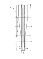
- FIG. 4 is a schematic longitudinal sectional view showing the distal portion DE of the tubular body 10 in an enlarged manner.
- the illustrated distal portion DE includes a tapered change portion B in which the outer diameter of the tubular main body 10 continuously decreases from the proximal end side toward the distal end side, and a proximal region closer to the change portion B. C and a distal region A that is more distal than the change portion B.
- the inner circumference of the main lumen 20 is also constant in the changing portion B.
- the inclination of the outer diameter of the tubular main body 10 may be the same throughout the changing portion B, or the inclination may change midway.
- the outer diameter of the main lumen 20 may be constant also in the changing part B, or may be the same inclination in the whole changing part B, or the inclination may change in the middle.
- the distal region A includes a first length region a1 and a second length region a2 further on the distal side than the first length region a1.
- FIG. 4 shows the position of the joining line D, which is a boundary between the first length region a1 and the second length region a2, that is, a boundary line obtained by joining resins having different hardnesses.
- the joining lines are indicated by joining lines D1, D2, and D3, respectively. 4 and 5, the position of the joining line is indicated by a straight line.
- the joining line D can be a curved line.
- the value of (Shore hardness of the first length region a1) / (Shore hardness of the second length region a2) is 1.1 or more and It is preferable to set it to 2.0 or less from the viewpoint of a balance excellent in blood vessel selectivity and guide wire followability in blood vessel branching while giving good blood vessel running property and torque property of the catheter. Further, when the value of (Shore hardness of the changed portion B) / (Shore hardness of the second length region a2) is 1.1 or more and 2.0 or less, it is possible to further improve the good vascular running property and torque property of the catheter.
- nylon elastomer is used for the outer layer 50 in the distal region A, the changed portion B, and the proximal region C, and the length, the outer diameter ⁇ of the outer layer 50 (in the cross section)
- the area hardness) and the Shore hardness of the outer layer 50 can be set as follows, for example.
- Distal region A length 15 mm, ⁇ 0.8 mm, Shore hardness 25D (second length region a2), 35D (first length region a1)
- Change part B Length 3 mm, ⁇ 0.9 mm to 0.8 mm, Shore hardness 35D
- Proximal region C Length 10mm, ⁇ 0.9mm, Shore hardness 35D That is, in the above configuration, the resin hardness of the outer layer 50 constituting the changing portion B and the proximal region C is uniform.
- the size and the resin hardness of the distal region A, the changed portion B, and the proximal region C are not limited to the above numerical values and ratios as a matter of course. The size and resin hardness of each part are determined according to the use of the catheter 1 and the like.
- FIG. 5A to FIG. 5C are diagrams showing a plurality of examples of the joining lines of the first length region a1 and the second length region a2 in the distal tubular body 10.
- FIG. 5A shows an example in which there is a joining line D1 in the vicinity of the changing portion B in the distal region A.
- the minimum distance between the joining line D1 and the end (distal end) at the most distal side of the change part B can be, for example, about the wall thickness in the joining line D1 of the tubular body 10, and more preferably. It is preferable that the length is longer than half (radius) of the outer diameter of the tubular body 10 at the boundary between the distal region A and the change part B.
- FIG. 5A shows an example in which there is a joining line D1 in the vicinity of the changing portion B in the distal region A.
- the minimum distance between the joining line D1 and the end (distal end) at the most distal side of the change part B can be, for example, about the wall thickness
- FIG. 5B shows the joining line D2 located closer to the tip T than the joining line D1.
- FIG. 5C shows a joining line D3 that is closer to the tip T than the joining line D2.
- the joining line can be anywhere in the distal region A. The closer the joining line D is to the distal end T, the stronger the stiffness near the distal end of the tubular body 10, and the stronger the characteristics of the catheter in terms of vessel running and torque. Conversely, as the joining line D is farther from the tip T, the stiffness near the tip of the tubular body 10 becomes weaker, and the blood vessel selectivity and guide wire followability of the catheter in the blood vessel branching are improved.
- the position of the joining line D is determined according to the use of the catheter 1 and the hardness of the resin material.
- switching of the resin material in the distal region A is not limited to one place, and may be performed in multiple stages at a plurality of places.
- the first length region a1 and the second length region a2 are not limited to those adjacent to each other, and may be disposed with another region interposed therebetween.
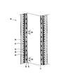
- FIGS. 6A and 6B are perspective views showing a portion of the distal region A in the tubular body 10, and a view showing a joining line D in the distal region A.
- FIG. 6A shows the entire distal region A
- FIG. 6B is an enlarged view of a portion indicated by a broken line e in FIG. 6A.
- the distance d from the plane (cross section S of the tubular body 10) perpendicular to the direction of the axis f of the tubular body 10 is not uniform in the joining line D on the distal region A.
- the distal region A is designed so that the unevenness of the joining line D is 1 cycle to 5 cycles. That is, the joining line D has a shape in which 1 to 5 convex portions protrude toward the tip T side or the base end side. The unevenness of the joining line D is more preferably 2 cycles to 5 cycles.
- blood vessel selectivity and guide wire followability in blood vessel branching are improved.
- it can prevent that a crack and damage arise in the boundary of 1st length area
- Even if slight variations occur in the position of the joining line D it is possible to absorb variations in functions such as blood vessel running performance and torque performance for each product of the catheter 1.
- the joining line D should just be a curve surrounding the circumference
- the tubular body 10 is thinned from the proximal end toward the distal end T, thereby reducing the morphological hardness of the tubular body 10 and forming the first length region a1. Therefore, the material having the lower hardness than the material of the first length region a1 is selected to be different from the material forming the second length region a2. In other words, the hardness of the distal region A of the tubular main body 10 is lower than the joining line D on the distal side of the change part B.
- the catheter 1 having such a tubular body 10 maintains a higher hardness than the invention described in Japanese Patent Laid-Open No.
- Patent Document 1 2012-196389 shown as Patent Document 1, and the vascular running property and torque characteristics of the tubular body 10 are maintained. Can be improved to prevent the occurrence of kinks. Moreover, since this embodiment can reduce the hardness of the tip T and soften the contact of the tip T of the tubular body 10 with the body cavity, damage, perforation, and spasm in the blood vessel can be prevented. Further, in the present embodiment, the resin material is switched in the distal region A. On the other hand, in the invention described in Patent Document 1, the resin material is switched at the displacement portion (taper portion). The operation of switching the resin material at a portion where the thickness continuously changes is more difficult than the operation of switching the resin material at a portion where the thickness is constant, and the switching position is likely to vary. Therefore, this embodiment can improve the reproducibility of the switching position of the resin material of the tubular body 10 as compared with the invention described in Patent Document 1.
- the tubular body 10 of the catheter 1 is formed by extruding the inner layer 24 into a mold that matches the shape of the inner layer 24.
- the wire reinforcing layer 30 is formed by winding the reinforcing wire 32 around the inner layer 24.
- the winding of the reinforcing wire 32 is performed by a dedicated device so that the winding pitch of the reinforcing wire 32 is constant.
- a plurality of subtubes 40 are arranged so as to be in contact with the outer surface of the wire reinforcing layer 30 and the holding wire 70 is wound to create a core material.
- a plurality of resin tubes corresponding to the proximal region C, the changing portion B, the first length region a1, and the second length region a2 are arranged and covered in this order from the proximal side on the core material.
- the resins corresponding to the proximal region C, the changed portion B, the first length region a1, and the second length region a2 are the proximal region C, the changed portion B, and the first length region a1. And it shows that it respond
- the tube that forms the outer layer 50 in the proximal region C, the changing portion B, the first length region a1, and the second length region a2 is prepared in advance by extrusion molding or the like, and the proximal region C, the changing portion B, Processing is performed to a length corresponding to the first length region a1 and the second length region a2.
- the resin tube serving as the first length region a1 and the resin tube serving as the second length region a2 are adjacent to each other.
- the surfaces facing each other are provided with irregularities, and these resin tubes are arranged and covered on the core material so that the irregularities are fitted to each other.
- the inner layer 24, the wire reinforcing layer 30, the sub-tube 40, and the resin tube are covered with a heat-shrink material and heated.
- the heating temperature is higher than the softening point temperature of the resin constituting the outer layer 50 (proximal region C, change part B, first length region a1 and second length region a2), although the softening point temperature is the highest. High temperature.
- the proximal region C, the changed portion B, the first length region a1, and the second length region a2 are fused and integrated at each boundary to form the outer layer 50.
- various processes such as forming a hydrophilic layer (not shown) on the surface of the outer layer 50 and inserting the operation line 60 into the sub-tube 40 are performed.
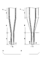
- FIG. 7A and FIG. 7B are diagrams for explaining a modification of the present embodiment.
- FIG. 7A is a longitudinal sectional view of a tubular body 11 which is a modification of the tubular body 10.
- the tubular body 11 shown in FIG. 7A has a tapered outer layer 51 in which both the outer diameter of the tubular body 11 and the outer diameter of the main lumen 20 continuously expand from the distal end toward the proximal end. .
- both the outer diameter of the tubular main body 11 and the outer diameter of the main lumen 20 are expanded with the same inclination (the wall thickness does not change) from the distal end toward the proximal end.
- FIG. 7B is a longitudinal sectional view of a tubular body 13 which is a modification of the tubular body 10.
- the tubular main body 13 shown in FIG. 7B has a tapered outer layer 53 in which both the outer diameter of the tubular main body 13 and the outer diameter of the main lumen 20 continuously expand from the distal end toward the proximal end. .
- the outer diameter of the tubular main body 13 expands from the distal end of the outer layer 53 toward the proximal end with a larger inclination than the outer diameter of the main lumen 20 (thickness increases).
- the catheter of the present embodiment is not limited to the configuration described above.
- the various components of the catheter 1 of this embodiment do not have to be individually independent.
- a plurality of components are formed as one member, a component is formed of a plurality of members, one component is a part of another component, and one component is And a part of other components are allowed to overlap.
- the first embodiment includes the following technical idea.
- a catheter including a resin-made tubular body having a changing portion in which the rigidity caused by the tubular shape in the axial direction continuously decreases from the proximal end side toward the distal end side, distal to the changing portion
- a first length region and a second length region distal to the first length region are defined in the tubular body on the side, and the second length is greater than the resin hardness of the first length region.
- a catheter characterized in that the resin hardness of the region is low.
- FIG. 2 is a cross-sectional view of the catheter 1 along the arrow II-II shown in FIG.
- FIG. 3 is a longitudinal sectional view of the catheter 1 along the arrow III-III shown in FIG.
- the catheter 1 of the present embodiment is an active catheter in which an operation line 60 is disposed inside the tubular body 10 and the distal end T of the tubular body 10 is bent by operating the operation unit 90 and the bending operation unit 92. is there.
- the catheter of the present invention is not limited to this, and may be an inactive catheter that does not include the operation line 60 or the operation unit 90.
- the catheter 1 of the present embodiment has an operation unit 90 provided at the proximal end of the tubular main body 10.
- the end opposite to the side where the tubular main body 10 is connected to the operation unit 90 is referred to as a tip T.
- the operation unit 90 constitutes an operation mechanism for performing a bending operation of the distal portion DE of the tubular main body 10 together with the operation line 60 (see FIGS. 2 and 3).
- the operation unit 90 of the present embodiment includes a main body case 94 that is held by an operator with a hand, and a bending operation unit 92 that is provided to be rotatable with respect to the main body case 94.
- the proximal end of the tubular main body 10 is introduced into the main body case 94.
- a concave portion 95 is formed in the main body case 94 at a position in contact with the bending operation portion 92.
- the concave portion 95 is provided with a slider 98 that slides forward and backward toward the bending operation portion 92.
- the operation unit 90 includes a hub 96 provided in communication with the main lumen 20 of the tubular main body 10.
- a syringe (not shown) is attached to the hub 96.
- the hub 96 is provided at the rear end of the main body case 94, and a syringe is attached from the rear of the hub 96.
- the chemical solution examples include a contrast agent, a liquid anticancer agent, physiological saline, a chemical solution such as NBCA (n-butyl-2-cyanoacrylate) used as an instantaneous adhesive, a detachable coil, a bead (emboli globular substance), and the like. Mention may be made of medical devices.
- NBCA n-butyl-2-cyanoacrylate
- the tubular body 10 has a first length region b1 (see FIG. 8) and a second length that is adjacent to the first length region and is more distal than the first length region. Region b2 (see FIG. 8).
- the resin hardness of the second length region is lower than the resin hardness of the first length region, and the joining line D (see FIG. 9) between the first length region and the second length region is the axial direction of the tubular body.
- the distance from the plane perpendicular to is uneven. That is, this embodiment defines a first length region having a predetermined length in the tubular body 10. Then, a second length region adjacent to the first length region is defined on the distal side of the first length region.
- the first length region and the second length region may have the same length or may have different lengths.
- the tubular body 10 is made of resin (hereinafter also referred to as “resin material”), and the hardness of the resin material in the second length region is lower than the hardness of the resin material in the first length region. Therefore, the tubular body 10 of the present embodiment has a portion where different regions of the resin material are adjacent. Adjacent different resin materials are partially melted and bonded to each other by heating and pressing.
- the joining line D of the first length region b1 and the second length region b2 has a non-uniform distance from the plane perpendicular to the axial direction of the tubular body, The hardness of the material gradually changes at the site. For this reason, the said structure can prevent generation
- the first length region b1, the second length region b2, and the joining line D will be described in detail later.
- the tubular main body 10 shown in FIG. 1 is also called a sheath, and is a hollow tubular and long member in which a main lumen (main lumen) 20 is formed.
- the tubular body 10 is a resin having a “change part” in which the rigidity caused by the tubular shape continuously decreases from the proximal end side toward the distal end side in the axial direction (the axis passing through the central point of the cross section of the main lumen 20).
- a tubular body made of Here, the “rigidity resulting from the tubular form” is the rigidity resulting from the inner diameter or outer shape of the tubular body 10 and the thickness of the tubular body 10.
- the “tubular form” includes at least one of the thickness, outer diameter, and inner diameter of the tubular body as an element.
- the rigidity resulting from the form of the tubular body 10 is small when the inner diameter or the outer diameter of the tubular body 10 is relatively thin, and is large when it is thick. Further, the tubular body 10 is larger if the wall thickness is relatively thick, and smaller if it is thin.
- the tubular body 10 is tubular without changing the outer diameter of the main lumen 20 from the distal end toward the proximal end.
- the main body 10 has a tapered shape in which the outer diameter continuously increases (thickness increases). If it does in this way, the rigidity resulting from the form of the tubular main body 10 will increase continuously from the front end T toward the base end.
- the tubular body 10 according to the present invention is not limited to the following laminated configuration.
- the tubular body 10 has a laminated structure.
- the tubular main body 10 is configured by laminating an inner layer (main tube) 24 and an outer layer 50 in order from the inner diameter side with the main lumen 20 as the center.
- a hydrophilic layer (not shown) is formed on the outer surface of the outer layer 50.
- the inner layer 24 and the outer layer 50 are formed of a flexible resin material, and each has a tubular shape and a substantially uniform thickness in the circumferential direction.
- the inner layer 24 is the innermost layer of the tubular body 10 and defines the main lumen 20 by the inner wall surface thereof.
- the shape of the cross section of the main lumen 20 is not particularly limited, but is circular in this embodiment.
- the term “cross section of the main lumen” refers to a cross section of a shape defined by the outer peripheral surface of the main lumen 20 (a long cylinder in the axial direction of the main lumen 20).
- the diameter of the cross section of the tubular body 10 is circular, and the diameter of the tubular body 10 differs depending on the position in the longitudinal direction (the axial direction of the main lumen 20). In a part or the entire length region, the diameter of the tubular body 10 is continuously increased from the distal end toward the proximal end.
- Examples of the material of the inner layer 24 include a fluorine-based thermoplastic polymer resin.
- Specific examples of the fluorine-based thermoplastic polymer material include polytetrafluoroethylene (PTFE), polyvinylidene fluoride (PVDF), and perfluoroalkoxy fluororesin (PFA).
- PTFE polytetrafluoroethylene
- PVDF polyvinylidene fluoride
- PFA perfluoroalkoxy fluororesin
- the wire reinforcement layer 30 is a protective layer that is provided on the inner diameter side of the operation line 60 in the tubular body 10 and protects the inner layer 24.
- the presence of the wire reinforcement layer 30 on the inner diameter side of the operation line 60 can prevent the operation line 60 from penetrating from the outer layer 50 to the inner layer 24 and exposed to the main lumen 20.
- the wire reinforcing layer 30 is formed by winding a reinforcing wire 32.
- the material of the reinforcing wire 32 includes a metal material such as tungsten (W), stainless steel (SUS), nickel titanium alloy, steel, titanium, copper, titanium alloy, or copper alloy, and is sheared more than the inner layer 24 and the outer layer 50.
- a resin material such as polyimide (PI), polyamideimide (PAI), or polyethylene terephthalate (PET) having high strength can be used.
- a fine stainless steel wire is used as the reinforcing wire 32.
- the number of strips and the number of meshes of the reinforcing wire 32 are not particularly limited.
- the number of meshes of the wire reinforcing layer 30 refers to the number of intersections (number of eyes) per unit length (1 inch) viewed in the extending direction of the reinforcing wires.
- the reinforcing wire 32 is wound obliquely around the inner layer 24.
- An angle formed by the extending direction of the reinforcing wire 32 with respect to the circumferential direction around the inner layer 24 is referred to as a pitch angle of the reinforcing wire 32.
- the pitch angle becomes a small angle.
- the pitch angle is a large angle close to 90 degrees.
- the pitch angle of the reinforcing wire 32 of the present embodiment is not particularly limited, but can be 30 degrees or more, preferably 45 degrees or more and 75 degrees or less.
- the number of reinforcing wires 32 constituting the wire reinforcing layer 30 is not particularly limited, but in this embodiment, the wire reinforcing layer 30 formed by 16 reinforcing wires 32 is illustrated.
- the subtube 40 is a hollow tubular member that defines a secondary lumen.
- the subtube 40 is embedded in the outer layer 50.
- the subtube 40 can be made of, for example, a thermoplastic polymer material.
- the thermoplastic polymer material include low friction resin materials such as polytetrafluoroethylene (PTFE), polyetheretherketone (PEEK), or tetrafluoroethylene / hexafluoropropylene copolymer (FEP).
- PTFE polytetrafluoroethylene
- PEEK polyetheretherketone
- FEP tetrafluoroethylene / hexafluoropropylene copolymer
- the subtube 40 is made of a material having a higher bending rigidity and tensile modulus than the outer layer 50.
- the two sub tubes 40 are arranged on the same circumference so as to surround the main lumen 20.
- the catheter 1 of the present embodiment is an active type, and includes the sub-tube 40 and the holding wire 70 in addition to the operation line 60 and the operation unit 90. However, such a configuration is not necessary when the catheter of the present embodiment is an inactive type.
- the operation line 60 is loosely inserted in the sub tube 40 so as to be slidable.
- the distal end of the operation line 60 is fixed to the distal portion DE of the tubular body 10.
- a tensile force is applied to a position eccentric with respect to the axis of the tubular body 10, so that the tubular body 10 bends.
- the operation wire 60 may be formed of a single wire, but may be a stranded wire formed by twisting a plurality of thin wires.
- the number of fine wires constituting one stranded wire of the operation wire 60 is not particularly limited, but is preferably 3 or more.
- the operation wire 60 a low carbon steel (piano wire), stainless steel (SUS), a steel wire coated with corrosion resistance, titanium or a titanium alloy, or a metal wire such as tungsten can be used.
- the operation line 60 includes polyvinylidene fluoride (PVDF), high density polyethylene (HDPE), poly (paraphenylenebenzobisoxazole) (PBO), polyetheretherketone (PEEK), polyphenylene sulfide (PPS), Polymer fibers such as polybutylene terephthalate (PBT), polyimide (PI), polytetrafluoroethylene (PTFE), or boron fiber can be used.
- PVDF polyvinylidene fluoride
- HDPE high density polyethylene
- PBO poly (paraphenylenebenzobisoxazole)
- PEEK polyetheretherketone
- PPS polyphenylene sulfide
- Polymer fibers such as polybutylene terephthalate (PBT), polyimide (PI
- the holding wire 70 is wound in a spiral shape so as to surround the outside of the pair of sub-tubes 40 that are opposed to each other around the main lumen 20.
- the winding shape of the holding wire 70 of the present embodiment is a substantially elliptical shape or a substantially rhombic shape in which the arrangement direction of the subtubes 40 is the major axis direction.
- FIG. 3 the holding wire 70 whose winding shape forms a substantially rhombus is illustrated by a broken line.
- the holding wire 70 is in contact with the peripheral surface of the subtube 40, specifically, the outer surface that is opposite to the axis of the main lumen 20.
- the approximate rhombus means that the first diagonal line is longer than the second diagonal line, and the first diagonal line and the second diagonal line are substantially orthogonal.
- the approximate rhombus mentioned here includes a rhombus, a flat polygon such as a kite shape, a flat hexagon, and a flat octagon.
- the substantially elliptical shape includes an elliptical shape such as an oval shape as well as an elliptical shape or an oval shape.
- the cross-sectional shape of the main lumen 20 is circular, and is arranged at the center of the tubular main body 10, and the two sub tubes 40 are arranged 180 degrees opposite to each other around the main lumen 20.
- the shape of the cross section of the main lumen 20 is not limited to a circle, and may be another shape such as an ellipse or a rectangle.
- the sub-tubes 40 may be equally distributed around the main lumen 20 of three or more (N).
- the winding shape of the holding wire 70 may be a rounded N-square shape with each subtube 40 as a corner.
- the holding wire 70 As the material of the holding wire 70, any of the above metal materials or resin materials that can be used as the reinforcing wire 32 can be used.
- the holding wire 70 is formed to include a material different from the reinforcing wire 32.
- the ductility of the holding wire 70 is preferably higher than the ductility of the reinforcing wire 32.
- austenitic soft stainless steel (W1 or W2) which is a dull material, or copper or copper alloy is used for the holding wire 70, while tungsten or stainless spring steel can be used for the reinforcing wire 32.
- the outer layer 50 is a tubular portion that constitutes the main wall thickness of the tubular body 10. Inside the outer layer 50, a wire reinforcing layer 30, a sub tube 40, and a holding wire 70 are provided in this order from the inner diameter side. The wire reinforcing layer 30 and the holding wire 70 are arranged coaxially with the tubular main body 10.
- the difference in resin hardness between the first length region and the second length region of the tubular body 10 means that the resin hardness of the outer layer 50 constituting the main thickness of the tubular body 10 is different.
- the outer layer 50 may be a single layer or a multilayer, and when the outer layer 50 is a multilayer, it indicates that the resin hardness of the first length region and the second length region are different for the thickest layer of the plurality of layers. .
- thermoplastic polymer material As the material of the outer layer 50 , a thermoplastic polymer material can be used. As this thermoplastic polymer material, polyimide (PI), polyamideimide (PAI), polyethylene terephthalate (PET), polyethylene (PE), polyamide (PA), polyamide elastomer (PAE), polyether block amide (PEBA), etc. Mention may be made of nylon elastomers, polyurethane (PU), ethylene-vinyl acetate resin (EVA), polyvinyl chloride (PVC) or polypropylene (PP).
- the outer layer 50 may be mixed with an inorganic filler. Examples of the inorganic filler include contrast agents such as barium sulfate and bismuth subcarbonate.
- the X-ray contrast property of the tubular body 10 in the body cavity can be improved.
- the resin hardness is switched by changing the resin material in the first length region and the resin material in the second length region, the resin material in the first length region and the resin material in the second length region have different hardness.
- the same kind is preferable in terms of adhesion.
- the same kind of resin material having different hardness means, for example, a resin material having different hardness due to a common resin structure and a different degree of crosslinking, or a different component or addition amount of filler or elastomer.
- FIG. 8 is a schematic longitudinal sectional view showing the distal portion DE of the tubular body 10 in an enlarged manner.
- the illustrated distal portion DE includes a tapered change portion B in which the outer diameter of the tubular main body 10 continuously decreases from the proximal end side toward the distal end side, and a proximal region closer to the change portion B. C and a distal region A that is more distal than the change portion B.
- the inner circumference of the main lumen 20 is also constant in the changing portion B.
- the inclination of the outer diameter of the tubular main body 10 may be the same throughout the changing portion B, or the inclination may change midway.
- the outer diameter of the main lumen 20 may be constant also in the changing part B, or may be the same inclination in the whole changing part B, or the inclination may change in the middle.
- the changing portion B is a portion in the tubular body 10 where the rigidity due to the form in the direction of the axis f continuously decreases from the base end K side toward the tip T side.
- the joining line D between the first length region b1 and the second length region b2 is formed in the changing portion B.
- joining line D is not limited to being provided at the changing portion B, but the distal region A, the boundary between the distal region A and the changing portion B, the boundary between the changing portion B and the proximal region C, It may be provided at any position on the position region C.
- the value of (Shore hardness of the first length region b1) / (Shore hardness of the second length region b2) is 1.1 or more and It is preferable to set it to 2.0 or less from the viewpoint of a balance excellent in blood vessel selectivity and guide wire followability in blood vessel branching while giving good blood vessel running property and torque property of the catheter. Further, when the value of (Shore hardness of the first length region b1) / (Shore hardness of the distal region A) is 1.1 or more and 2.0 or less, further good blood vessel running property and torque property of the catheter are achieved.
- nylon elastomer is used for the outer layer 50 in the distal region A, the changed portion B, and the proximal region C, and the length, the diameter ⁇ of the main lumen 20 (in the cross section)
- the area hardness) and the Shore hardness of the outer layer 50 can be set as follows, for example.
- Distal region A length 15 mm, ⁇ 0.8 mm, Shore hardness 25D
- Change part B Length 10 mm, ⁇ 0.8 mm to 0.9 mm, Shore hardness 35D (first length region b1, length 5 mm), Shore hardness 25D (second length region b2, length 5 mm)
- Proximal region C Length 10mm, ⁇ 0.9mm, Shore hardness 35D That is, in the above configuration, the resin hardness of the outer layer 50 constituting the first length region b1 and the proximal region C is uniform.
- the size and the resin hardness of the distal region A, the changed portion B, and the proximal region C are not limited to the above numerical values and ratios as a matter of course. The size and resin hardness of each part are determined according to the use of the catheter 1 and the like.
- FIG. 9A and FIG. 9B are perspective views showing the changed portion B in the tubular body 10 and showing the joining line D in the changed portion B.
- FIG. FIG. 9A shows the entire change portion B
- FIG. 9B is an enlarged view of a portion indicated by a broken line e in FIG.
- the joining line D on the change part B has a non-uniform distance d from a plane perpendicular to the direction of the axis f of the tubular body 10 (cross section S of the tubular body 10).
- the distance d from the cross section S refers to the distance d between one point on the cross section S and the intersection of the joining line D with a line extending from this one point in parallel with the axis f.
- the distance d varies depending on the position on the cross section S.
- FIG. 10A and FIG. 10B are diagrams for explaining the bonding line D.
- the vertical axis indicates the distance from the cross section S to the joining line D (including the distance to the apex of the convex part and the apex of the concave part).
- the horizontal axis indicates the circumferential length of the cross section S passing through one point on the joining line D continuous in the circumferential direction of the tubular body 10.
- FIG. 10A shows one example of the joining line D in which the combination of the convex portion and the concave portion is at least one set in the circumferential direction of the tubular main body 10. In the example shown in FIG.
- FIG. 10A shows one example in which there are at least two combinations of convex portions and concave portions in the circumferential direction of the tubular main body 10.
- the combination is not limited to three, and any number of two or three or more may be used. Also good.
- the member that becomes the first length region b1 and the member that becomes the second length region b2 are opposed to each other. Unevenness is formed in advance.
- the shape of the concave portion and the convex portion can be sufficiently controlled by the unevenness formed in advance, the shape of the concave portion and the convex portion of the joining line D can be made substantially the same.
- the joining line D only needs to be a curve surrounding the periphery of the change part B of the tubular body 10, and the period of irregularities and the amplitude of irregularities may be constant or random.
- the first length region b1 and the second length region b2 are joined with the intention that the joining line D is a curve.
- the joining line D has a waveform having a larger amplitude than the joining line that draws a curve unintentionally in the joining process.
- the difference in the axial distance between the most distal side (indicated by the tip T) of the joining line D and the most proximal end K side is shown as the length dd1.
- the difference in the distance between the most distal side and the most proximal end K of the joining line D in the axial direction is shown as the length dd2.
- the tubular body 10 has a laminated structure including at least the inner layer 24 and the outer layer 50.
- the length dd1 and the length dd2 are both equal to or greater than the wall thickness of the outer layer 50 at the position based on the joining line D on the tubular body 10 (one times the wall thickness), 3 of the outer diameter of the tubular body 10. It shall be less than double. In this way, the resin having different hardness between the first length region b1 and the second length region b2 sufficiently enters the other, and between the first length region b1 and the second length region b2. Changes in hardness can be moderated.
- the “position based on the joining line D” in the present embodiment is, for example, the position of the transverse section S 1/2 of the tubular body 10 including a point that halves the lengths dd1 and dd2 of the joining line D. Also good. At this time, the thickness of the outer layer becomes the thickness of the outer layer 50 of the tubular main body 10 at a position intersecting the cross section S1 / 2 .
- the lengths dd1 and dd2 may be, for example, not less than the radius of the cross section S or not less than the radius and not more than three times the radius.
- the concave portion or the convex portion of the joining line D has a shape that protrudes toward the distal end T or the proximal end.
- the hardness gradually changes in the joining line D, and when the catheter 1 is bent, the region extending from the changed portion B to the distal region A is smoothly curved, and cracks are generated on the changed portion B. And damage (kinks) can be prevented.
- the change in hardness becomes more gradual in the change part B. For this reason, even if slight variations occur in the position of the joining line D, it is possible to absorb variations in functions such as blood vessel running properties, blood vessel running properties, and torque properties for each product of the catheter 1.
- the tubular body 10 of the catheter 1 is formed by extruding the inner layer 24 into a mold that matches the shape of the inner layer 24.
- the reinforcing wire 32 is wound around the inner layer 24 to form the wire reinforcing layer 30.
- the reinforcing wire 32 is wound by a dedicated device so that the winding pitch is constant.
- a plurality of subtubes 40 are arranged so as to be in contact with the outer surface of the wire reinforcing layer 30 and the holding wire 70 is wound to create a core material.
- a plurality of resin tubes corresponding to the proximal region C, the first length region b1, the second length region b2, and the distal region A are arranged and covered in this order from the proximal side.
- the resins corresponding to the proximal region C, the first length region b1, the second length region b2, and the distal region A are the proximal region C, the change portion B, and the first length region. It shows that it respond
- the tube forming the outer layer 50 in the proximal region C, the first length region b1, the second length region b2, and the distal region A is prepared in advance by extrusion or the like, and the proximal region C, the first length A length corresponding to the length region b1, the second length region b2, and the distal region A is processed.
- the resin tube serving as the first length region b1 and the resin tube serving as the second length region b2 are adjacent to each other.
- the surfaces facing each other are provided with irregularities, and these resin tubes are arranged and covered on the core material so that the irregularities are fitted to each other.
- the inner layer 24, the wire reinforcing layer 30, the sub-tube 40, and the resin tube are covered with a heat-shrink material and heated.
- the heating temperature is higher than the softening point temperature of the resin constituting the outer layer 50 (proximal region C, first length region b1, second length region b2 and distal region A) having the highest softening point temperature.
- the temperature is also high.
- FIG. 7A and FIG. 7B are diagrams for explaining a modification of the present embodiment.
- FIG. 7A is a longitudinal sectional view of a tubular body 11 which is a modification of the tubular body 10.
- the tubular body 11 shown in FIG. 7A has a tapered outer layer 51 in which both the outer diameter of the tubular body 11 and the outer diameter of the main lumen 20 continuously expand from the distal end toward the proximal end. .
- both the outer diameter of the tubular main body 11 and the outer diameter of the main lumen 20 are expanded with the same inclination (the wall thickness does not change) from the distal end toward the proximal end.
- FIG. 7B is a longitudinal sectional view of a tubular body 13 which is a modification of the tubular body 10.
- the tubular main body 13 shown in FIG. 7B has a tapered outer layer 53 in which both the outer diameter of the tubular main body 13 and the outer diameter of the main lumen 20 continuously expand from the distal end toward the proximal end. .
- the outer diameter of the tubular main body 13 expands from the distal end of the outer layer 53 toward the proximal end with a larger inclination than the outer diameter of the main lumen 20 (thickness increases). Yes.
- the proximal region C2 is thicker than the distal region A2, but the thickness of each is constant.
- the catheter of the present embodiment is not limited to the configuration described above.
- the various components of the catheter 1 of this embodiment do not have to be individually independent.
- a plurality of components are formed as one member, a component is formed of a plurality of members, one component is a part of another component, and one component is And a part of other components are allowed to overlap.
- the second embodiment includes the following technical idea.
- a catheter comprising a tubular body, wherein the tubular body is adjacent to the first length region and the first length region, and is a second length located on the distal side of the first length region. And the resin length of the second length region is lower than the resin hardness of the first length region, and the joining line of the first length region and the second length region is the tubular A catheter having a non-uniform distance from a plane perpendicular to the axial direction of the main body.
- the joining line has at least one pair of a concave portion and a convex portion in a circumferential direction of the tubular main body.
- the catheter according to (1) wherein the joint line has at least two combinations of a concave portion and a convex portion in the circumferential direction of the tubular main body, and has a shape in which the concave portion and the convex portion are arranged in series.
- the tubular body has a laminated structure including at least an inner layer and an outer layer, and the difference in the axial distance between the most distal side and the most proximal side of the joining line is caused by the joining line of the tubular body.
- the catheter according to any one of (1) to (3) which is not less than a thickness of the outer layer at a base position and not more than three times an outer diameter of the tubular body.
- the tubular main body has a changing portion in which rigidity due to the tubular shape in the axial direction continuously decreases from the proximal end side toward the distal end side.
- the joining line between the first length region and the second length region is formed in the change portion.
- the tubular form is at least one element among a thickness, an outer diameter, and an inner diameter of the tubular body.
Abstract
The present invention provides a catheter provided with a tubular body. The catheter is characterized in that: the tubular body has defined therein a first length region and a second length region which is adjacent to the first length region and which is located closer to the distal end side than the first length region; the resin hardness of the second length region is lower than the resin hardness of the first length region; and the distance from a plane perpendicular to the axial direction of the tubular body to the joint line between the first length region and the second length region is non-uniform.
Description
本発明は、カテーテルに関する。
The present invention relates to a catheter.
カテーテルには、血管等の体腔内に挿入された際に体組織に過剰な負荷をかけない柔軟性と同時に、カテーテルの良好な走行性や血管選択性、トルク性を得るために好適な「コシ」を持つことが望まれている。なお、本明細書において、コシとは、弾力、硬度及び可撓性等によって決まるカテーテルの体腔内に挿入される部分(本体)の特性をいう。カテーテルのコシが好適であれば、カテーテルは術者の操作に追従して体腔内において動作することができる。
The catheter has a flexibility that does not apply an excessive load to the body tissue when inserted into a body cavity such as a blood vessel, and at the same time, is suitable for obtaining good running performance, blood vessel selectivity, and torque characteristics of the catheter. It is hoped to have. In this specification, the term “koshi” refers to the characteristics of the portion (main body) inserted into the body cavity of the catheter determined by elasticity, hardness, flexibility, and the like. If the stiffness of the catheter is suitable, the catheter can move in the body cavity following the operation of the operator.
例えば、特許文献1には、カテーテルの近位端部から遠位端部に向けて段階的にカテーテルの外層の硬度を低くすることが記載されている。より具体的には、特許文献1に記載のカテーテルは、その本体が内層、外層及び内層と外層との間に設けられる中間層を有するチューブである。チューブには先端から基端に向かって直径が連続的に拡大するテーパー状の部分がある。
特許文献1には、カテーテル本体のテーパー状の部分を、遠位端部に向けて材料となる樹脂の硬度を段階的に小さくし、かつ、直径が細くなるようにして遠位端部に行くほどカテーテル本体の剛性を小さくすることが記載されている。 For example,Patent Document 1 describes that the hardness of the outer layer of the catheter is gradually reduced from the proximal end portion to the distal end portion of the catheter. More specifically, the catheter described in Patent Document 1 is a tube having a main body having an inner layer, an outer layer, and an intermediate layer provided between the inner layer and the outer layer. The tube has a tapered portion whose diameter continuously increases from the distal end to the proximal end.
InPatent Document 1, the taper-shaped portion of the catheter main body is made to go to the distal end portion in such a manner that the hardness of the resin as a material is gradually reduced toward the distal end portion and the diameter is reduced. It is described that the rigidity of the catheter body is reduced.
特許文献1には、カテーテル本体のテーパー状の部分を、遠位端部に向けて材料となる樹脂の硬度を段階的に小さくし、かつ、直径が細くなるようにして遠位端部に行くほどカテーテル本体の剛性を小さくすることが記載されている。 For example,
In
ところで、カテーテル本体の剛性をチューブの軸線方向に沿って変化させる場合には、硬度が異なる材料を軸線方向に切り替える、あるいはチューブの管状形態に起因する剛性を変えることになる。
カテーテル本体の剛性は、材料の切り替え位置やチューブの管状形態によって変化するが、材料の切り替え位置のばらつきは、カテーテルの剛性、ひいては血管選択性や血管進行性、トルク性といった機能のばらつきとなって表れる。このため、カテーテル本体の機能をコントロールするためには、カテーテル毎の材料の切り替え位置のばらつきを抑えることが望ましい。
また、材料が切り替えられる位置において硬度が急峻に変化すると、切り替え位置にてカテーテル本体が折れるという現象(以下、「キンク」とも記す)が発生する可能性がある。このため、カテーテルを取り扱う現場では、カテーテルの耐キンク性を高めることが望まれている。 By the way, when the rigidity of the catheter body is changed along the axial direction of the tube, materials having different hardnesses are switched in the axial direction, or the rigidity caused by the tubular form of the tube is changed.
The rigidity of the catheter body varies depending on the material switching position and the tubular shape of the tube, but the variation in the material switching position is a variation in the rigidity of the catheter, and thus functions such as vessel selectivity, vessel progression, and torque. appear. For this reason, in order to control the function of the catheter body, it is desirable to suppress variations in the material switching position for each catheter.
In addition, when the hardness changes sharply at a position where the material is switched, there is a possibility that a phenomenon that the catheter body is broken at the switching position (hereinafter also referred to as “kink”) may occur. For this reason, in the field where a catheter is handled, it is desired to improve the kink resistance of the catheter.
しかしながら、上記した特許文献1には、材料の切り替え位置の製品毎のばらつきを抑えるための構成について、一切記載されていない。
上記した特許文献1には、カテーテル本体の耐キンク性を高めるための構成について、一切記載されていない。
本発明は、上記の点に鑑みてなされたものであり、軸線方向の材料の硬度を切り替えながら切り替え位置のばらつきを抑えて製造安定性に優れ、ひいては血管選択性や血管走行性、トルク性といった機能のばらつきが少ないカテーテルを提供することを目的とする。
また、本発明は、上記の点に鑑みてなされたものであり、軸線方向の材料の硬度を切り替えながら、硬度の不連続性に起因するキンクの発生を防ぐことが可能なカテーテルを提供することを目的とする。
However, the above-describedPatent Document 1 does not describe any configuration for suppressing the variation of the material switching position for each product.
Patent Document 1 described above does not describe any configuration for improving the kink resistance of the catheter body.
The present invention has been made in view of the above points, and is excellent in manufacturing stability by suppressing the variation of the switching position while switching the hardness of the material in the axial direction. As a result, the blood vessel selectivity, the blood vessel running property, the torque property, etc. An object of the present invention is to provide a catheter with little variation in function.
Further, the present invention has been made in view of the above points, and provides a catheter capable of preventing the occurrence of kinks due to hardness discontinuity while switching the hardness of the material in the axial direction. With the goal.
上記した特許文献1には、カテーテル本体の耐キンク性を高めるための構成について、一切記載されていない。
本発明は、上記の点に鑑みてなされたものであり、軸線方向の材料の硬度を切り替えながら切り替え位置のばらつきを抑えて製造安定性に優れ、ひいては血管選択性や血管走行性、トルク性といった機能のばらつきが少ないカテーテルを提供することを目的とする。
また、本発明は、上記の点に鑑みてなされたものであり、軸線方向の材料の硬度を切り替えながら、硬度の不連続性に起因するキンクの発生を防ぐことが可能なカテーテルを提供することを目的とする。
However, the above-described
The present invention has been made in view of the above points, and is excellent in manufacturing stability by suppressing the variation of the switching position while switching the hardness of the material in the axial direction. As a result, the blood vessel selectivity, the blood vessel running property, the torque property, etc. An object of the present invention is to provide a catheter with little variation in function.
Further, the present invention has been made in view of the above points, and provides a catheter capable of preventing the occurrence of kinks due to hardness discontinuity while switching the hardness of the material in the axial direction. With the goal.
本発明によれば、軸線方向において管状形態に起因する剛性が基端側から先端側に向けて連続的に小さくなる変化部を有する樹脂製の管状本体を備えるカテーテルであって、前記変化部よりも遠位側の管状本体において第1長さ領域と前記第1長さ領域よりも遠位側にある第2長さ領域とが規定され、前記第1長さ領域の樹脂硬度よりも前記第2長さ領域の樹脂硬度が低い、カテーテルが提供される。
According to the present invention, the catheter includes a resin tubular body having a changing portion in which the rigidity due to the tubular shape in the axial direction continuously decreases from the proximal end side toward the distal end side, A first length region and a second length region distal to the first length region in the tubular body on the distal side are defined, and the first length region is more than the resin hardness of the first length region. A catheter is provided that has a low resin hardness in the two-length region.
また、本発明によれば、管状本体を備えるカテーテルであって、前記管状本体には第1長さ領域と前記第1長さ領域に隣接し、かつ前記第1長さ領域よりも遠位側にある第2長さ領域とが規定され、前記第1長さ領域の樹脂硬度よりも前記第2長さ領域の樹脂硬度が低く、前記第1長さ領域と前記第2長さ領域の接合ラインは、前記管状本体の軸線方向に垂直な平面からの距離が不均一となっていることを特徴とするカテーテルが提供される。
According to the present invention, there is provided a catheter having a tubular body, the tubular body being adjacent to the first length region and the first length region, and further to the distal side than the first length region. The second length region is defined, the resin hardness of the second length region is lower than the resin hardness of the first length region, and the first length region and the second length region are joined. The catheter is characterized in that the line has a non-uniform distance from a plane perpendicular to the axial direction of the tubular body.
本発明によれば、軸線方向の剛性を切り替えながら切り替え位置のばらつきを抑えて製造安定性に優れ、ひいては血管選択性や血管走行性、トルク性といった機能のばらつきが少ないカテーテルを提供することができる。
また、本発明によれば、軸線方向の剛性を切り替えながら、剛性の不連続性に起因するキンクの発生を防ぐことが可能なカテーテルを提供することができる。 According to the present invention, it is possible to provide a catheter that is excellent in manufacturing stability by suppressing the variation in switching position while switching the rigidity in the axial direction, and has little variation in functions such as blood vessel selectivity, blood vessel running property, and torque property. .
Further, according to the present invention, it is possible to provide a catheter capable of preventing the occurrence of kinks due to rigidity discontinuity while switching the rigidity in the axial direction.
以下、本発明の実施形態を図面に基づいて説明する。なお、すべての図面において、同様の構成要素には同一符号を付し、その詳細な説明は重複しないように適宜省略する。
Hereinafter, embodiments of the present invention will be described with reference to the drawings. In all the drawings, the same components are denoted by the same reference numerals, and detailed description thereof is omitted as appropriate so as not to overlap.
〔第一実施形態〕
(カテーテル)
図1は、本発明の第一実施形態のカテーテル1を説明するための図である。図2は、図1中に示した矢線II-IIに沿うカテーテル1の横断面図である。図3は、図2中に示した矢線III-IIIに沿うカテーテル1の縦断面図である。なお、本実施形態のカテーテル1は、管状本体10の内部に操作線60が配置されていて、操作部90、屈曲操作部92を操作することで管状本体10の先端Tが屈曲する能動カテーテルである。ただし、本発明のカテーテルは、これに限定されず、操作線60や操作部90を備えていない非能動型のカテーテルであってもよい。
本実施形態のカテーテル1は、管状本体10の基端に設けられた操作部90を有している。また、管状本体10が操作部90と接続されている側の反対の端部を、先端Tとする。操作部90は、操作線60(図2、図3参照)とともに、管状本体10の遠位部DEの屈曲操作を行うための操作機構を構成している。本実施形態の操作部90は、術者が手で把持する本体ケース94と、本体ケース94に対して回転可能に設けられた屈曲操作部92と、を有している。管状本体10の基端は、本体ケース94の内部に導入されている。本体ケース94には、屈曲操作部92に接する位置に凹部95が形成されている。凹部95には、屈曲操作部92に向かって進退自在に摺動するスライダ98が設けられている。 [First embodiment]
(catheter)
Drawing 1 is a figure for explainingcatheter 1 of a first embodiment of the present invention. FIG. 2 is a cross-sectional view of the catheter 1 along the arrow II-II shown in FIG. FIG. 3 is a longitudinal sectional view of the catheter 1 along the arrow III-III shown in FIG. The catheter 1 of the present embodiment is an active catheter in which an operation line 60 is disposed inside the tubular body 10 and the distal end T of the tubular body 10 is bent by operating the operation unit 90 and the bending operation unit 92. is there. However, the catheter of the present invention is not limited to this, and may be an inactive catheter that does not include the operation line 60 or the operation unit 90.
Thecatheter 1 of the present embodiment has an operation unit 90 provided at the proximal end of the tubular main body 10. The end opposite to the side where the tubular main body 10 is connected to the operation unit 90 is referred to as a tip T. The operation unit 90 constitutes an operation mechanism for performing a bending operation of the distal portion DE of the tubular main body 10 together with the operation line 60 (see FIGS. 2 and 3). The operation unit 90 of the present embodiment includes a main body case 94 that is held by an operator with a hand, and a bending operation unit 92 that is provided to be rotatable with respect to the main body case 94. The proximal end of the tubular main body 10 is introduced into the main body case 94. A concave portion 95 is formed in the main body case 94 at a position in contact with the bending operation portion 92. The concave portion 95 is provided with a slider 98 that slides forward and backward toward the bending operation portion 92.
(カテーテル)
図1は、本発明の第一実施形態のカテーテル1を説明するための図である。図2は、図1中に示した矢線II-IIに沿うカテーテル1の横断面図である。図3は、図2中に示した矢線III-IIIに沿うカテーテル1の縦断面図である。なお、本実施形態のカテーテル1は、管状本体10の内部に操作線60が配置されていて、操作部90、屈曲操作部92を操作することで管状本体10の先端Tが屈曲する能動カテーテルである。ただし、本発明のカテーテルは、これに限定されず、操作線60や操作部90を備えていない非能動型のカテーテルであってもよい。
本実施形態のカテーテル1は、管状本体10の基端に設けられた操作部90を有している。また、管状本体10が操作部90と接続されている側の反対の端部を、先端Tとする。操作部90は、操作線60(図2、図3参照)とともに、管状本体10の遠位部DEの屈曲操作を行うための操作機構を構成している。本実施形態の操作部90は、術者が手で把持する本体ケース94と、本体ケース94に対して回転可能に設けられた屈曲操作部92と、を有している。管状本体10の基端は、本体ケース94の内部に導入されている。本体ケース94には、屈曲操作部92に接する位置に凹部95が形成されている。凹部95には、屈曲操作部92に向かって進退自在に摺動するスライダ98が設けられている。 [First embodiment]
(catheter)
Drawing 1 is a figure for explaining
The
操作部90は、管状本体10の主管腔20と連通して設けられたハブ96を備えている。ハブ96にはシリンジ(図示せず)が装着される。ハブ96は本体ケース94の後端部に設けられており、ハブ96の後方からシリンジが装着される。シリンジによってハブ96内に薬液等を注入することにより、管状本体10の中空部である主管腔20(図2、図3)を介して薬液等を被験者の体腔内へ供給することができる。薬液等としては、造影剤、液体抗ガン剤、生理食塩水、瞬間接着剤として用いられるNBCA(n-butyl-2-cianoacrylate)等の薬液の他、デタッチャブルコイルやビーズ(塞栓球状物質)等の医療用デバイスを挙げることができる。
The operation unit 90 includes a hub 96 provided in communication with the main lumen 20 of the tubular main body 10. A syringe (not shown) is attached to the hub 96. The hub 96 is provided at the rear end of the main body case 94, and a syringe is attached from the rear of the hub 96. By injecting the drug solution or the like into the hub 96 with a syringe, the drug solution or the like can be supplied into the body cavity of the subject through the main lumen 20 (FIGS. 2 and 3) which is a hollow portion of the tubular main body 10. Examples of the chemical solution include a contrast agent, a liquid anticancer agent, physiological saline, a chemical solution such as NBCA (n-butyl-2-cyanoacrylate) used as an instantaneous adhesive, a detachable coil, a bead (emboli globular substance), and the like. Mention may be made of medical devices.
図1に示した管状本体10は、シースとも呼ばれ、内部に主管腔(メインルーメン)20が通孔形成された中空管状かつ長尺の部材である。より具体的には、管状本体10は、血管内に進入させることが可能な外径に形成されている。管状本体10は、軸線(主管腔20の横断面の中心点を通る軸)方向において管状形態に起因する剛性が基端側から先端側に向けて連続的に小さくなる「変化部」を有する樹脂製の管状本体である。ここで、「管状形態に起因する剛性」とは、管状本体10の内径あるいは外径、さらには管状本体10の肉厚に起因する剛性である。つまり、「管状形態」は、管状本体の肉厚、外径又は内径のうち少なくとも一つを要素とする。管状本体10の形態に起因する剛性は、管状本体10の内径または外径が相対的に細ければ小さく、太ければ大きくなる。また、管状本体10の肉厚が相対的に厚ければ大きく、薄ければ小さくなる。
管状本体10の管状形態に起因する剛性を「連続的」に変化させるため、本実施形態の一例では、管状本体10を、先端から基端に向かって主管腔20の外径を変えずに管状本体10の外径が連続的に拡大(肉厚が厚くなる)するテーパー状とする。このようにすれば、管状本体10の形態に起因する剛性は、先端Tから基端に向けて連続的に大きくなる。 The tubularmain body 10 shown in FIG. 1 is also called a sheath, and is a hollow tubular and long member in which a main lumen (main lumen) 20 is formed. More specifically, the tubular main body 10 is formed to have an outer diameter that allows entry into the blood vessel. The tubular body 10 is a resin having a “change part” in which the rigidity caused by the tubular shape continuously decreases from the proximal end side toward the distal end side in the axial direction (the axis passing through the central point of the cross section of the main lumen 20). A tubular body made of Here, the “rigidity resulting from the tubular form” is the rigidity resulting from the inner diameter or outer diameter of the tubular body 10 and the wall thickness of the tubular body 10. That is, the “tubular form” includes at least one of the thickness, outer diameter, and inner diameter of the tubular body as an element. The rigidity resulting from the form of the tubular body 10 is small when the inner diameter or the outer diameter of the tubular body 10 is relatively thin, and is large when it is thick. Further, the tubular body 10 is larger if the wall thickness is relatively thick, and smaller if it is thin.
In order to change the rigidity due to the tubular shape of thetubular body 10 “continuously”, in the example of the present embodiment, the tubular body 10 is tubular without changing the outer diameter of the main lumen 20 from the distal end toward the proximal end. The main body 10 has a tapered shape in which the outer diameter continuously increases (thickness increases). If it does in this way, the rigidity resulting from the form of the tubular main body 10 will increase continuously from the front end T toward the base end.
管状本体10の管状形態に起因する剛性を「連続的」に変化させるため、本実施形態の一例では、管状本体10を、先端から基端に向かって主管腔20の外径を変えずに管状本体10の外径が連続的に拡大(肉厚が厚くなる)するテーパー状とする。このようにすれば、管状本体10の形態に起因する剛性は、先端Tから基端に向けて連続的に大きくなる。 The tubular
In order to change the rigidity due to the tubular shape of the
また、管状本体10は、上記変化部よりも遠位側の管状本体において第1長さ領域a1(図4参照)と、この第1長さ領域よりも遠位側にある第2長さ領域a2(図4参照)とが規定される。本実施形態では、第1長さ領域の樹脂硬度よりも第2長さ領域の樹脂硬度が低くなっている。即ち、本実施形態では、管状本体10は、テーパー状の部位よりも遠位側(先端T側)の所定の長さの範囲を第1長さ領域とする。さらに、第1長さ領域よりもさらに遠位側にある所定の長さの範囲を第2長さ領域とする。そして、第2長さ領域の材料の硬度が、第1長さ領域の材料の硬度よりも低くなるように第1長さ領域の材料と第2長さ領域の材料とを切り替えている。
なお、第1長さ領域a1、第2長さ領域a2については後に詳述する。 In addition, thetubular body 10 includes a first length region a1 (see FIG. 4) in the tubular body distal to the change portion, and a second length region located distal to the first length region. a2 (see FIG. 4) is defined. In the present embodiment, the resin hardness of the second length region is lower than the resin hardness of the first length region. That is, in the present embodiment, the tubular body 10 has a first length region in a predetermined length range distal to the tapered portion (tip T side). Furthermore, a range of a predetermined length further on the distal side than the first length region is set as the second length region. Then, the material of the first length region and the material of the second length region are switched so that the hardness of the material of the second length region is lower than the hardness of the material of the first length region.
The first length region a1 and the second length region a2 will be described in detail later.
なお、第1長さ領域a1、第2長さ領域a2については後に詳述する。 In addition, the
The first length region a1 and the second length region a2 will be described in detail later.
ここで、第1長さ領域、第2長さ領域の説明に先立って、管状本体10の構造の一例について説明する。ただし、本発明に係る管状本体10は、以下の積層構成に限られるものではない。
図2、図3に示すように、管状本体10は積層構造を有している。管状本体10は、主管腔20を中心に、内径側から順に内層(メインチューブ)24及び外層50が積層されて構成されている。外層50の外表面には親水層(不図示)が形成されている。内層24及び外層50は可撓性の樹脂材料で形成されていて、それぞれ円管状で周方向に略均一の厚みを有している。 Here, prior to the description of the first length region and the second length region, an example of the structure of the tubularmain body 10 will be described. However, the tubular body 10 according to the present invention is not limited to the following laminated configuration.
As shown in FIGS. 2 and 3, thetubular body 10 has a laminated structure. The tubular main body 10 is configured by laminating an inner layer (main tube) 24 and an outer layer 50 in order from the inner diameter side with the main lumen 20 as the center. A hydrophilic layer (not shown) is formed on the outer surface of the outer layer 50. The inner layer 24 and the outer layer 50 are formed of a flexible resin material, and each has a tubular shape and a substantially uniform thickness in the circumferential direction.
図2、図3に示すように、管状本体10は積層構造を有している。管状本体10は、主管腔20を中心に、内径側から順に内層(メインチューブ)24及び外層50が積層されて構成されている。外層50の外表面には親水層(不図示)が形成されている。内層24及び外層50は可撓性の樹脂材料で形成されていて、それぞれ円管状で周方向に略均一の厚みを有している。 Here, prior to the description of the first length region and the second length region, an example of the structure of the tubular
As shown in FIGS. 2 and 3, the
内層24は管状本体10の最内層であり、その内壁面により主管腔20を画定する。主管腔20の横断面の形状は特に限定されないが、本実施形態では円形である。なお、本明細書において、「主管腔の横断面」の文言は、主管腔20の外周面によって画定される形状(主管腔20の軸線方向に長い円柱)の横断面を指す。また、本実施形態では、管状本体10の横断面の直径は円形であり、その管状本体10の直径は長手方向(主管腔20の軸線方向)の位置により相違していて、管状本体10の一部又は全部の長さ領域において、先端から基端に向かって管状本体10の直径が連続的に拡大するテーパー状とする。
The inner layer 24 is the innermost layer of the tubular body 10 and defines the main lumen 20 by the inner wall surface thereof. The shape of the cross section of the main lumen 20 is not particularly limited, but is circular in this embodiment. In the present specification, the term “cross section of the main lumen” refers to a cross section of a shape defined by the outer peripheral surface of the main lumen 20 (a long cylinder in the axial direction of the main lumen 20). In the present embodiment, the diameter of the cross section of the tubular body 10 is circular, and the diameter of the tubular body 10 differs depending on the position in the longitudinal direction (the axial direction of the main lumen 20). In a part or the entire length region, the diameter of the tubular body 10 is continuously increased from the distal end toward the proximal end.
内層24の材料は、例えば、フッ素系の熱可塑性ポリマー樹脂を挙げることができる。このフッ素系の熱可塑性ポリマー材料としては、具体的には、ポリテトラフルオロエチレン(PTFE)、ポリビニリデンフルオライド(PVDF)及びペルフルオロアルコキシフッ素樹脂(PFA)を挙げることができる。内層24をこのようなフッ素系ポリマー材料で構成することにより、主管腔20を通じて薬液等を供給する際のデリバリー性が良好となる。また、主管腔20にガイドワイヤーなどを挿通する際の摺動抵抗が低減される。
Examples of the material of the inner layer 24 include a fluorine-based thermoplastic polymer resin. Specific examples of the fluorine-based thermoplastic polymer material include polytetrafluoroethylene (PTFE), polyvinylidene fluoride (PVDF), and perfluoroalkoxy fluororesin (PFA). By configuring the inner layer 24 with such a fluorine-based polymer material, the delivery property when supplying a drug solution or the like through the main lumen 20 is improved. Further, sliding resistance when a guide wire or the like is inserted through the main lumen 20 is reduced.
ワイヤ補強層30は、管状本体10のうち操作線60よりも内径側に設けられて内層24を保護する保護層である。操作線60の内径側にワイヤ補強層30が存在することで、操作線60が外層50から内層24へと貫通し主管腔20に露出することを防止することができる。
The wire reinforcement layer 30 is a protective layer that is provided on the inner diameter side of the operation line 60 in the tubular body 10 and protects the inner layer 24. The presence of the wire reinforcement layer 30 on the inner diameter side of the operation line 60 can prevent the operation line 60 from penetrating from the outer layer 50 to the inner layer 24 and exposed to the main lumen 20.
ワイヤ補強層30は補強ワイヤ32を巻回して形成されている。補強ワイヤ32の材料には、タングステン(W)、ステンレス鋼(SUS)、ニッケルチタン系合金、鋼、チタン、銅、チタン合金または銅合金などの金属材料のほか、内層24および外層50よりも剪断強度が高いポリイミド(PI)、ポリアミドイミド(PAI)またはポリエチレンテレフタレート(PET)などの樹脂材料を用いることができる。本実施形態では、補強ワイヤ32としてステンレス鋼の細線が用いられている。
補強ワイヤ32の条数やメッシュ数は特に限定されない。ここで、ワイヤ補強層30のメッシュ数とは、補強ワイヤの延在方向にみた単位長さ(1インチ)あたりの交差本数(目の数)をいう。 Thewire reinforcing layer 30 is formed by winding a reinforcing wire 32. The material of the reinforcing wire 32 includes a metal material such as tungsten (W), stainless steel (SUS), nickel titanium alloy, steel, titanium, copper, titanium alloy, or copper alloy, and is sheared more than the inner layer 24 and the outer layer 50. A resin material such as polyimide (PI), polyamideimide (PAI), or polyethylene terephthalate (PET) having high strength can be used. In the present embodiment, a fine stainless steel wire is used as the reinforcing wire 32.
The number of strips and the number of meshes of the reinforcingwire 32 are not particularly limited. Here, the number of meshes of the wire reinforcing layer 30 refers to the number of intersections (number of eyes) per unit length (1 inch) viewed in the extending direction of the reinforcing wires.
補強ワイヤ32の条数やメッシュ数は特に限定されない。ここで、ワイヤ補強層30のメッシュ数とは、補強ワイヤの延在方向にみた単位長さ(1インチ)あたりの交差本数(目の数)をいう。 The
The number of strips and the number of meshes of the reinforcing
補強ワイヤ32は、内層24の周囲に斜めに巻回されている。内層24の周囲における円周方向に対する補強ワイヤ32の延在方向の為す角を、補強ワイヤ32のピッチ角という。補強ワイヤ32が密ピッチで巻回されている場合、ピッチ角は小さな角度になる。逆に補強ワイヤ32が管状本体10の軸線に沿って浅い角度で巻回されている場合、ピッチ角は90度に近い大きな角度になる。本実施形態の補強ワイヤ32のピッチ角は特に限定されないが、30度以上、好ましくは45度以上、かつ75度以下とすることができる。
ワイヤ補強層30を構成する補強ワイヤ32の条数は特に限定されないが、本実施形態においては16条の補強ワイヤ32により形成されたワイヤ補強層30が図示されている。 The reinforcingwire 32 is wound obliquely around the inner layer 24. An angle formed by the extending direction of the reinforcing wire 32 with respect to the circumferential direction around the inner layer 24 is referred to as a pitch angle of the reinforcing wire 32. When the reinforcing wires 32 are wound at a dense pitch, the pitch angle becomes a small angle. Conversely, when the reinforcing wire 32 is wound at a shallow angle along the axis of the tubular body 10, the pitch angle is a large angle close to 90 degrees. The pitch angle of the reinforcing wire 32 of the present embodiment is not particularly limited, but can be 30 degrees or more, preferably 45 degrees or more and 75 degrees or less.
The number of reinforcingwires 32 constituting the wire reinforcing layer 30 is not particularly limited, but in this embodiment, the wire reinforcing layer 30 formed by 16 reinforcing wires 32 is illustrated.
ワイヤ補強層30を構成する補強ワイヤ32の条数は特に限定されないが、本実施形態においては16条の補強ワイヤ32により形成されたワイヤ補強層30が図示されている。 The reinforcing
The number of reinforcing
サブチューブ40は副管腔を画定する中空管状の部材である。サブチューブ40は外層50の内部に埋設されている。サブチューブ40は、たとえば熱可塑性ポリマー材料により構成することができる。その熱可塑性ポリマー材料としては、ポリテトラフルオロエチレン(PTFE)、ポリエーテルエーテルケトン(PEEK)、または四フッ化エチレン・六フッ化プロピレン共重合体(FEP)などの低摩擦樹脂材料が挙げられる。サブチューブ40は、外層50よりも曲げ剛性率および引張弾性率が高い材料で構成されている。
2本のサブチューブ40は、主管腔20を取り囲むように、同一の円周上に配置されている。本実施形態に代えて、3本または4本のサブチューブ40を主管腔20の周囲に等間隔で配置してもよい。この場合、総てのサブチューブ40に操作線60を配置してもよく、または一部のサブチューブ40に操作線60を配置してもよい。サブチューブ40には副管腔42が形成され、副管腔42内に操作線60が移動可能に挿入される。
なお、上述したように、本実施形態のカテーテル1は能動型であり、操作線60、操作部90の他、サブチューブ40、保持ワイヤ70を備えている。
ただし、本実施形態のカテーテルを非能動型とする場合、このような構成は不要である。 Thesubtube 40 is a hollow tubular member that defines a secondary lumen. The subtube 40 is embedded in the outer layer 50. The subtube 40 can be made of, for example, a thermoplastic polymer material. Examples of the thermoplastic polymer material include low friction resin materials such as polytetrafluoroethylene (PTFE), polyetheretherketone (PEEK), or tetrafluoroethylene / hexafluoropropylene copolymer (FEP). The subtube 40 is made of a material having a higher bending rigidity and tensile elastic modulus than the outer layer 50.
The twosub tubes 40 are arranged on the same circumference so as to surround the main lumen 20. Instead of this embodiment, three or four subtubes 40 may be arranged around the main lumen 20 at equal intervals. In this case, the operation lines 60 may be arranged on all the sub tubes 40 or the operation lines 60 may be arranged on some of the sub tubes 40. A sub-lumen 42 is formed in the sub-tube 40, and an operation line 60 is movably inserted into the sub-lumen 42.
As described above, thecatheter 1 of the present embodiment is an active type, and includes the sub-tube 40 and the holding wire 70 in addition to the operation line 60 and the operation unit 90.
However, such a configuration is not necessary when the catheter of the present embodiment is an inactive type.
2本のサブチューブ40は、主管腔20を取り囲むように、同一の円周上に配置されている。本実施形態に代えて、3本または4本のサブチューブ40を主管腔20の周囲に等間隔で配置してもよい。この場合、総てのサブチューブ40に操作線60を配置してもよく、または一部のサブチューブ40に操作線60を配置してもよい。サブチューブ40には副管腔42が形成され、副管腔42内に操作線60が移動可能に挿入される。
なお、上述したように、本実施形態のカテーテル1は能動型であり、操作線60、操作部90の他、サブチューブ40、保持ワイヤ70を備えている。
ただし、本実施形態のカテーテルを非能動型とする場合、このような構成は不要である。 The
The two
As described above, the
However, such a configuration is not necessary when the catheter of the present embodiment is an inactive type.
操作線60は、サブチューブ40に対して摺動可能に遊挿されている。操作線60の先端は管状本体10の遠位部DEに固定されている。操作線60を基端側に牽引することで、管状本体10の軸線に対して偏心した位置に引張力が付与されるため管状本体10は屈曲する。このため、分岐している血管のうち任意の血管を選択してカテーテル1を容易に進入させることができる。
操作線60は、単一の線材により構成されていてもよいが、複数本の細線を互いに撚りあわせることにより構成された撚り線であってもよい。操作線60の一本の撚り線を構成する細線の本数は特に限定されないが、3本以上であることが好ましい。 Theoperation line 60 is loosely inserted in the sub tube 40 so as to be slidable. The distal end of the operation line 60 is fixed to the distal portion DE of the tubular body 10. By pulling the operation line 60 to the proximal end side, a tensile force is applied to a position eccentric with respect to the axis of the tubular body 10, so that the tubular body 10 bends. For this reason, it is possible to easily enter the catheter 1 by selecting an arbitrary blood vessel among the branched blood vessels.
Theoperation wire 60 may be formed of a single wire, but may be a stranded wire formed by twisting a plurality of thin wires. The number of fine wires constituting one stranded wire of the operation wire 60 is not particularly limited, but is preferably 3 or more.
操作線60は、単一の線材により構成されていてもよいが、複数本の細線を互いに撚りあわせることにより構成された撚り線であってもよい。操作線60の一本の撚り線を構成する細線の本数は特に限定されないが、3本以上であることが好ましい。 The
The
操作線60としては、低炭素鋼(ピアノ線)、ステンレス鋼(SUS)、耐腐食性被覆した鋼鉄線、チタンもしくはチタン合金、またはタングステンなどの金属線を用いることができる。このほか、操作線60としては、ポリビニリデンフルオライド(PVDF)、高密度ポリエチレン(HDPE)、ポリ(パラフェニレンベンゾビスオキサゾール)(PBO)、ポリエーテルエーテルケトン(PEEK)、ポリフェニレンスルフィド(PPS)、ポリブチレンテレフタレート(PBT)、ポリイミド(PI)、ポリテトラフルオロエチレン(PTFE)、またはボロン繊維などの高分子ファイバーを用いることができる。
As the operation wire 60, a low carbon steel (piano wire), stainless steel (SUS), a steel wire coated with corrosion resistance, titanium or a titanium alloy, or a metal wire such as tungsten can be used. In addition, the operation line 60 includes polyvinylidene fluoride (PVDF), high density polyethylene (HDPE), poly (paraphenylenebenzobisoxazole) (PBO), polyetheretherketone (PEEK), polyphenylene sulfide (PPS), Polymer fibers such as polybutylene terephthalate (PBT), polyimide (PI), polytetrafluoroethylene (PTFE), or boron fiber can be used.
保持ワイヤ70は、主管腔20の周囲に対向配置された一対のサブチューブ40の外側を取り囲んで螺旋状に巻回されている。本実施形態の保持ワイヤ70の巻回形状は、サブチューブ40の並び方向を長径方向とする略楕円形または略菱形である。図3では、巻回形状が略菱形をなす保持ワイヤ70を破線で図示してある。保持ワイヤ70は、サブチューブ40の周面、具体的には主管腔20の軸線とは反対側にあたる外側表面に接している。ここで、略菱形とは、第一の対角線が第二の対角線よりも長く、かつ当該第一の対角線と当該第二の対角線とが略直交していることを意味している。ここでいう略菱形は、菱形のほか、凧形(カイト形)や、偏平六角形や偏平八角形などの偏平多角形を含む。また、略楕円形は、楕円形や長円形のほか、卵形などの偏心円形を含む。
The holding wire 70 is wound in a spiral shape so as to surround the outside of the pair of sub-tubes 40 that are opposed to each other around the main lumen 20. The winding shape of the holding wire 70 of the present embodiment is a substantially elliptical shape or a substantially rhombic shape in which the arrangement direction of the subtubes 40 is the major axis direction. In FIG. 3, the holding wire 70 whose winding shape forms a substantially rhombus is illustrated by a broken line. The holding wire 70 is in contact with the peripheral surface of the subtube 40, specifically, the outer surface that is opposite to the axis of the main lumen 20. Here, the approximate rhombus means that the first diagonal line is longer than the second diagonal line, and the first diagonal line and the second diagonal line are substantially orthogonal. The approximate rhombus mentioned here includes a rhombus, a flat polygon such as a kite shape, a flat hexagon, and a flat octagon. The substantially elliptical shape includes an elliptical shape such as an oval shape as well as an elliptical shape or an oval shape.
本実施形態では主管腔20の横断面の形状が円形であり、管状本体10の中心に配置され、2本のサブチューブ40が主管腔20の周囲に180度対向して配置されている態様を例示したが、主管腔20の横断面の形状は円形に限定されず、楕円や矩形等の他の形状であってもよい。また、サブチューブ40は、3本以上(N本)主管腔20の周囲に均等に分散配置されていてもよい。この場合、保持ワイヤ70の巻回形状は、各サブチューブ40をコーナーとする角丸N角形となってもよい。
In this embodiment, the cross-sectional shape of the main lumen 20 is circular, and is arranged at the center of the tubular main body 10, and the two sub tubes 40 are arranged 180 degrees opposite to each other around the main lumen 20. Although illustrated, the shape of the cross section of the main lumen 20 is not limited to a circle, and may be another shape such as an ellipse or a rectangle. In addition, the sub-tubes 40 may be equally distributed around the main lumen 20 of three or more (N). In this case, the winding shape of the holding wire 70 may be a rounded N-square shape with each subtube 40 as a corner.
保持ワイヤ70の材料としては、補強ワイヤ32として使用可能な上記の金属材料または樹脂材料のいずれかを用いることができる。本実施形態では、保持ワイヤ70は補強ワイヤ32と異種の材料を含み形成されている。保持ワイヤ70の延性は、補強ワイヤ32の延性よりも高いことが好ましい。具体的には、鈍し材であるオーステナイト系の軟質ステンレス鋼(W1またはW2)や、銅または銅合金を保持ワイヤ70に用いる一方、補強ワイヤ32にはタングステンやステンレスバネ鋼を用いることができる。
As the material of the holding wire 70, any of the above metal materials or resin materials that can be used as the reinforcing wire 32 can be used. In the present embodiment, the holding wire 70 is formed to include a material different from the reinforcing wire 32. The ductility of the holding wire 70 is preferably higher than the ductility of the reinforcing wire 32. Specifically, austenitic soft stainless steel (W1 or W2), which is a dull material, or copper or copper alloy is used for the holding wire 70, while tungsten or stainless spring steel can be used for the reinforcing wire 32. .
外層50は、管状本体10の主要な肉厚を構成する円管状の部分である。外層50の内部には、内径側から順にワイヤ補強層30と、サブチューブ40と、保持ワイヤ70が設けられている。ワイヤ補強層30と、保持ワイヤ70とは、管状本体10と同軸に配置されている。
本実施形態において、管状本体10の第1長さ領域と第2長さ領域の樹脂硬度が異なるとは、管状本体10の主要な肉厚を構成する外層50の樹脂硬度が異なることをいう。ただし、外層50は一層でも多層でもよく、外層50が多層であるときは、複数の層の最も肉厚が大きい層について第1長さ領域と第2長さ領域の樹脂硬度が異なることを指す。 Theouter layer 50 is a tubular portion that constitutes the main wall thickness of the tubular body 10. Inside the outer layer 50, a wire reinforcing layer 30, a sub tube 40, and a holding wire 70 are provided in this order from the inner diameter side. The wire reinforcing layer 30 and the holding wire 70 are arranged coaxially with the tubular main body 10.
In the present embodiment, the difference in resin hardness between the first length region and the second length region of thetubular body 10 means that the resin hardness of the outer layer 50 constituting the main thickness of the tubular body 10 is different. However, the outer layer 50 may be a single layer or a multilayer, and when the outer layer 50 is a multilayer, it indicates that the resin hardness of the first length region and the second length region are different for the thickest layer of the plurality of layers. .
本実施形態において、管状本体10の第1長さ領域と第2長さ領域の樹脂硬度が異なるとは、管状本体10の主要な肉厚を構成する外層50の樹脂硬度が異なることをいう。ただし、外層50は一層でも多層でもよく、外層50が多層であるときは、複数の層の最も肉厚が大きい層について第1長さ領域と第2長さ領域の樹脂硬度が異なることを指す。 The
In the present embodiment, the difference in resin hardness between the first length region and the second length region of the
外層50の材料としては熱可塑性ポリマー材料を用いることができる。この熱可塑性ポリマー材料としては、ポリイミド(PI)、ポリアミドイミド(PAI)、ポリエチレンテレフタレート(PET)、ポリエチレン(PE)、ポリアミド(PA)、ポリアミドエラストマー(PAE)、ポリエーテルブロックアミド(PEBA)などのナイロンエラストマー、ポリウレタン(PU)、エチレン-酢酸ビニル樹脂(EVA)、ポリ塩化ビニル(PVC)またはポリプロピレン(PP)を挙げることができる。
外層50には無機フィラーを混合してもよい。無機フィラーとしては、硫酸バリウムや次炭酸ビスマスなどの造影剤を例示することができる。外層50に造影剤を混合することで、体腔内における管状本体10のX線造影性を向上することができる。
第1長さ領域の樹脂材料と第2長さ領域の樹脂材料とを異ならせて樹脂硬度を切り替える場合、第1長さ領域の樹脂材料と第2長さ領域の樹脂材料は、硬度が異なる同種のものが密着性の点で好ましい。硬度が異なる同種の樹脂材料とは、例えば、樹脂の構造に共通性があって、架橋の程度が異なる、あるいはフィラーやエラストマーの成分や添加量が異なるなどして硬度が異なる樹脂材料をいう。 As the material of theouter layer 50, a thermoplastic polymer material can be used. As this thermoplastic polymer material, polyimide (PI), polyamideimide (PAI), polyethylene terephthalate (PET), polyethylene (PE), polyamide (PA), polyamide elastomer (PAE), polyether block amide (PEBA), etc. Mention may be made of nylon elastomers, polyurethane (PU), ethylene-vinyl acetate resin (EVA), polyvinyl chloride (PVC) or polypropylene (PP).
Theouter layer 50 may be mixed with an inorganic filler. Examples of the inorganic filler include contrast agents such as barium sulfate and bismuth subcarbonate. By mixing a contrast agent in the outer layer 50, the X-ray contrast property of the tubular body 10 in the body cavity can be improved.
When the resin hardness is switched by changing the resin material in the first length region and the resin material in the second length region, the resin material in the first length region and the resin material in the second length region have different hardness. The same kind is preferable in terms of adhesion. The same kind of resin material having different hardness means, for example, a resin material having different hardness due to a common resin structure and a different degree of crosslinking, or a different component or addition amount of filler or elastomer.
外層50には無機フィラーを混合してもよい。無機フィラーとしては、硫酸バリウムや次炭酸ビスマスなどの造影剤を例示することができる。外層50に造影剤を混合することで、体腔内における管状本体10のX線造影性を向上することができる。
第1長さ領域の樹脂材料と第2長さ領域の樹脂材料とを異ならせて樹脂硬度を切り替える場合、第1長さ領域の樹脂材料と第2長さ領域の樹脂材料は、硬度が異なる同種のものが密着性の点で好ましい。硬度が異なる同種の樹脂材料とは、例えば、樹脂の構造に共通性があって、架橋の程度が異なる、あるいはフィラーやエラストマーの成分や添加量が異なるなどして硬度が異なる樹脂材料をいう。 As the material of the
The
When the resin hardness is switched by changing the resin material in the first length region and the resin material in the second length region, the resin material in the first length region and the resin material in the second length region have different hardness. The same kind is preferable in terms of adhesion. The same kind of resin material having different hardness means, for example, a resin material having different hardness due to a common resin structure and a different degree of crosslinking, or a different component or addition amount of filler or elastomer.
次に、上記した本実施形態の変化部、第1長さ領域及び第2長さ領域について説明する。
図4は、管状本体10の遠位部DEを拡大して示した模式的な縦断面図である。図示した遠位部DEは、管状本体10の外径が基端側から先端側に向けて連続的に小さくなるテーパー状の変化部Bと、変化部Bよりも近位側にある近位領域Cと、変化部Bよりも遠位側にある遠位領域Aと、を有している。なお、主管腔20の内周は、変化部Bにおいても一定である。管状本体10の外径の傾斜は、変化部Bの間全てで同じでもよく、途中で傾斜が変化してもよい。主管腔20の外径は、変化部Bにおいても一定であってもよく、あるいは変化部Bの間全てで同じ傾斜でもよく、途中で傾斜が変化してもよい。また、遠位領域Aには、第1長さ領域a1と、第1長さ領域a1よりも更に遠位側にある第2長さ領域a2とが含まれる。図4中に、第1長さ領域a1と第2長さ領域a2との境界、つまり、硬度が異なる樹脂同士を接合した境界線である接合ラインDの位置を示す。また、図5では、接合ラインをそれぞれ接合ラインD1、D2、D3で示す。なお、図4及び図5では接合ラインの位置を直線で示すが、後述するように、本実施形態では、接合ラインDを曲線とすることができる。 Next, the changing portion, the first length region, and the second length region of the above-described embodiment will be described.
FIG. 4 is a schematic longitudinal sectional view showing the distal portion DE of thetubular body 10 in an enlarged manner. The illustrated distal portion DE includes a tapered change portion B in which the outer diameter of the tubular main body 10 continuously decreases from the proximal end side toward the distal end side, and a proximal region closer to the change portion B. C and a distal region A that is more distal than the change portion B. Note that the inner circumference of the main lumen 20 is also constant in the changing portion B. The inclination of the outer diameter of the tubular main body 10 may be the same throughout the changing portion B, or the inclination may change midway. The outer diameter of the main lumen 20 may be constant also in the changing part B, or may be the same inclination in the whole changing part B, or the inclination may change in the middle. Further, the distal region A includes a first length region a1 and a second length region a2 further on the distal side than the first length region a1. FIG. 4 shows the position of the joining line D, which is a boundary between the first length region a1 and the second length region a2, that is, a boundary line obtained by joining resins having different hardnesses. Further, in FIG. 5, the joining lines are indicated by joining lines D1, D2, and D3, respectively. 4 and 5, the position of the joining line is indicated by a straight line. However, as will be described later, in the present embodiment, the joining line D can be a curved line.
図4は、管状本体10の遠位部DEを拡大して示した模式的な縦断面図である。図示した遠位部DEは、管状本体10の外径が基端側から先端側に向けて連続的に小さくなるテーパー状の変化部Bと、変化部Bよりも近位側にある近位領域Cと、変化部Bよりも遠位側にある遠位領域Aと、を有している。なお、主管腔20の内周は、変化部Bにおいても一定である。管状本体10の外径の傾斜は、変化部Bの間全てで同じでもよく、途中で傾斜が変化してもよい。主管腔20の外径は、変化部Bにおいても一定であってもよく、あるいは変化部Bの間全てで同じ傾斜でもよく、途中で傾斜が変化してもよい。また、遠位領域Aには、第1長さ領域a1と、第1長さ領域a1よりも更に遠位側にある第2長さ領域a2とが含まれる。図4中に、第1長さ領域a1と第2長さ領域a2との境界、つまり、硬度が異なる樹脂同士を接合した境界線である接合ラインDの位置を示す。また、図5では、接合ラインをそれぞれ接合ラインD1、D2、D3で示す。なお、図4及び図5では接合ラインの位置を直線で示すが、後述するように、本実施形態では、接合ラインDを曲線とすることができる。 Next, the changing portion, the first length region, and the second length region of the above-described embodiment will be described.
FIG. 4 is a schematic longitudinal sectional view showing the distal portion DE of the
第1長さ領域a1と第2長さ領域a2との樹脂硬度に関し、(第1長さ領域a1のショア硬度)/(第2長さ領域a2のショア硬度)の値を1.1以上かつ2.0以下とすることが、カテーテルの良好な血管走行性やトルク性を持たせつつ、血管分岐における血管選択性やガイドワイヤー追従性に優れたバランスの観点から好ましい。また、(変化部Bのショア硬度)/(第2長さ領域a2のショア硬度)の値を1.1以上かつ2.0以下とすることがさらなるカテーテルの良好な血管走行性やトルク性を持たせつつ、血管分岐における血管選択性やガイドワイヤー追従性に優れたバランスの観点から好ましい。
このうち図4に示した例においては、遠位領域A、変化部B、近位領域Cにおける外層50にはいずれもナイロンエラストマーを用い、その長さ、外層50の外径φ(横断面の面積の指標)、外層50のショア硬度は、例えば以下のようにすることができる。
遠位領域A:長さ15mm、φ0.8mm、ショア硬度25D(第2長さ領域a2)、35D(第1長さ領域a1)
変化部B:長さ3mm、φ0.9mmから0.8mm、ショア硬度35D
近位領域C:長さ10mm、φ0.9mm、ショア硬度35D
すなわち上記構成において、変化部Bおよび近位領域Cを構成する外層50の樹脂硬度は、それぞれ均一である。
ただし、遠位領域A、変化部B、近位領域Cのサイズや樹脂硬度は、当然のことながら、上記した数値や比に限定されるものではない。各部位のサイズ及び樹脂硬度は、カテーテル1の用途等に応じて決定される。 Regarding the resin hardness of the first length region a1 and the second length region a2, the value of (Shore hardness of the first length region a1) / (Shore hardness of the second length region a2) is 1.1 or more and It is preferable to set it to 2.0 or less from the viewpoint of a balance excellent in blood vessel selectivity and guide wire followability in blood vessel branching while giving good blood vessel running property and torque property of the catheter. Further, when the value of (Shore hardness of the changed portion B) / (Shore hardness of the second length region a2) is 1.1 or more and 2.0 or less, it is possible to further improve the good vascular running property and torque property of the catheter. It is preferable from the viewpoint of a balance excellent in blood vessel selectivity and guide wire followability in blood vessel branching.
In the example shown in FIG. 4, nylon elastomer is used for theouter layer 50 in the distal region A, the changed portion B, and the proximal region C, and the length, the outer diameter φ of the outer layer 50 (in the cross section) The area hardness) and the Shore hardness of the outer layer 50 can be set as follows, for example.
Distal region A: length 15 mm, φ0.8 mm, Shore hardness 25D (second length region a2), 35D (first length region a1)
Change part B: Length 3 mm, φ0.9 mm to 0.8 mm, Shore hardness 35D
Proximal region C: Length 10mm, φ0.9mm, Shore hardness 35D
That is, in the above configuration, the resin hardness of theouter layer 50 constituting the changing portion B and the proximal region C is uniform.
However, the size and the resin hardness of the distal region A, the changed portion B, and the proximal region C are not limited to the above numerical values and ratios as a matter of course. The size and resin hardness of each part are determined according to the use of thecatheter 1 and the like.
このうち図4に示した例においては、遠位領域A、変化部B、近位領域Cにおける外層50にはいずれもナイロンエラストマーを用い、その長さ、外層50の外径φ(横断面の面積の指標)、外層50のショア硬度は、例えば以下のようにすることができる。
遠位領域A:長さ15mm、φ0.8mm、ショア硬度25D(第2長さ領域a2)、35D(第1長さ領域a1)
変化部B:長さ3mm、φ0.9mmから0.8mm、ショア硬度35D
近位領域C:長さ10mm、φ0.9mm、ショア硬度35D
すなわち上記構成において、変化部Bおよび近位領域Cを構成する外層50の樹脂硬度は、それぞれ均一である。
ただし、遠位領域A、変化部B、近位領域Cのサイズや樹脂硬度は、当然のことながら、上記した数値や比に限定されるものではない。各部位のサイズ及び樹脂硬度は、カテーテル1の用途等に応じて決定される。 Regarding the resin hardness of the first length region a1 and the second length region a2, the value of (Shore hardness of the first length region a1) / (Shore hardness of the second length region a2) is 1.1 or more and It is preferable to set it to 2.0 or less from the viewpoint of a balance excellent in blood vessel selectivity and guide wire followability in blood vessel branching while giving good blood vessel running property and torque property of the catheter. Further, when the value of (Shore hardness of the changed portion B) / (Shore hardness of the second length region a2) is 1.1 or more and 2.0 or less, it is possible to further improve the good vascular running property and torque property of the catheter. It is preferable from the viewpoint of a balance excellent in blood vessel selectivity and guide wire followability in blood vessel branching.
In the example shown in FIG. 4, nylon elastomer is used for the
Distal region A: length 15 mm, φ0.8 mm, Shore hardness 25D (second length region a2), 35D (first length region a1)
Change part B: Length 3 mm, φ0.9 mm to 0.8 mm, Shore hardness 35D
Proximal region C: Length 10mm, φ0.9mm, Shore hardness 35D
That is, in the above configuration, the resin hardness of the
However, the size and the resin hardness of the distal region A, the changed portion B, and the proximal region C are not limited to the above numerical values and ratios as a matter of course. The size and resin hardness of each part are determined according to the use of the
図5(a)から図5(c)は、遠位側の管状本体10における第1長さ領域a1と第2長さ領域a2の接合ラインの複数の例を示した図である。図5(a)は、遠位領域Aのうち、変化部Bに近接して接合ラインD1がある例を示している。接合ラインD1と変化部Bの最も遠位側にある端部(遠位端)との最小限の距離は、例えば管状本体10の接合ラインD1における肉厚程度とすることができ、より好ましくは、遠位領域Aと変化部Bとの境界における管状本体10の外径の半分(半径)より長いとよい。
図5(b)は、接合ラインD1よりも先端Tに近い位置にある接合ラインD2を示している。また、図5(c)は、接合ラインD2よりもさらに先端Tに近い位置にある接合ラインD3を示している。このように、接合ラインは遠位領域Aのどこにあってもよい。接合ラインDが先端Tに近い位置にあるほど管状本体10の先端付近のコシが強くなり、カテーテルの血管走行性やトルク性の特徴が強くなる。また、逆に、接合ラインDが先端Tから遠い位置にあるほど管状本体10の先端付近のコシが弱くなり、血管分岐におけるカテーテルの血管選択性やガイドワイヤー追従性がよくなる。接合ラインDの位置は、カテーテル1の用途や樹脂材料の硬度等に応じて決定される。
なお、遠位領域Aにおける樹脂材料の切り替えは、一箇所に限定されるものでなく、複数の箇所で多段階に行われるものであってもよい。また、第1長さ領域a1、第2長さ領域a2は隣接するものに限定されず、間に他の領域を挟んで配置されるものであってもよい。 FIG. 5A to FIG. 5C are diagrams showing a plurality of examples of the joining lines of the first length region a1 and the second length region a2 in the distaltubular body 10. FIG. 5A shows an example in which there is a joining line D1 in the vicinity of the changing portion B in the distal region A. FIG. The minimum distance between the joining line D1 and the end (distal end) at the most distal side of the change part B can be, for example, about the wall thickness in the joining line D1 of the tubular body 10, and more preferably. It is preferable that the length is longer than half (radius) of the outer diameter of the tubular body 10 at the boundary between the distal region A and the change part B.
FIG. 5B shows the joining line D2 located closer to the tip T than the joining line D1. FIG. 5C shows a joining line D3 that is closer to the tip T than the joining line D2. Thus, the joining line can be anywhere in the distal region A. The closer the joining line D is to the distal end T, the stronger the stiffness near the distal end of thetubular body 10, and the stronger the characteristics of the catheter in terms of vessel running and torque. Conversely, as the joining line D is farther from the tip T, the stiffness near the tip of the tubular body 10 becomes weaker, and the blood vessel selectivity and guide wire followability of the catheter in the blood vessel branching are improved. The position of the joining line D is determined according to the use of the catheter 1 and the hardness of the resin material.
In addition, switching of the resin material in the distal region A is not limited to one place, and may be performed in multiple stages at a plurality of places. Further, the first length region a1 and the second length region a2 are not limited to those adjacent to each other, and may be disposed with another region interposed therebetween.
図5(b)は、接合ラインD1よりも先端Tに近い位置にある接合ラインD2を示している。また、図5(c)は、接合ラインD2よりもさらに先端Tに近い位置にある接合ラインD3を示している。このように、接合ラインは遠位領域Aのどこにあってもよい。接合ラインDが先端Tに近い位置にあるほど管状本体10の先端付近のコシが強くなり、カテーテルの血管走行性やトルク性の特徴が強くなる。また、逆に、接合ラインDが先端Tから遠い位置にあるほど管状本体10の先端付近のコシが弱くなり、血管分岐におけるカテーテルの血管選択性やガイドワイヤー追従性がよくなる。接合ラインDの位置は、カテーテル1の用途や樹脂材料の硬度等に応じて決定される。
なお、遠位領域Aにおける樹脂材料の切り替えは、一箇所に限定されるものでなく、複数の箇所で多段階に行われるものであってもよい。また、第1長さ領域a1、第2長さ領域a2は隣接するものに限定されず、間に他の領域を挟んで配置されるものであってもよい。 FIG. 5A to FIG. 5C are diagrams showing a plurality of examples of the joining lines of the first length region a1 and the second length region a2 in the distal
FIG. 5B shows the joining line D2 located closer to the tip T than the joining line D1. FIG. 5C shows a joining line D3 that is closer to the tip T than the joining line D2. Thus, the joining line can be anywhere in the distal region A. The closer the joining line D is to the distal end T, the stronger the stiffness near the distal end of the
In addition, switching of the resin material in the distal region A is not limited to one place, and may be performed in multiple stages at a plurality of places. Further, the first length region a1 and the second length region a2 are not limited to those adjacent to each other, and may be disposed with another region interposed therebetween.
図6(a)、図6(b)は、管状本体10における遠位領域Aの部分を示した斜視図であって、遠位領域Aにおける接合ラインDを示した図である。図6(a)は遠位領域Aの全体を示し、図6(b)は図6(a)の破線eで示した部分の拡大図である。遠位領域A上の接合ラインDは、管状本体10の軸線fの方向に垂直な平面(管状本体10の横断面S)からの距離dが不均一となっている。ここで、横断面Sからの距離dは、横断面Sの円周上の一点と、この一点から軸線fと平行に延ばした線と接合ラインDとの交点との距離dを指し、横断面Sは接合ラインDの最も基端側にある点と接している(d=0)。図6(b)に示すように、距離dは、接合ラインDの位置によって異なっている。本実施形態では、接合ラインDの凹凸が1周期から5周期になるように遠位領域Aを設計している。すなわち、接合ラインDは、1個から5個の凸部が先端Tの側または基端の側に突出するような形状を有している。また、接合ラインDの凹凸は、2周期から5周期がより好ましい。このようにすれば、接合ラインDにおいて硬度が緩やかに変化し、カテーテル1を曲げた際に第1長さ領域a1から第2長さ領域a2に亘る領域が滑らかに湾曲するようになり、また、血管分岐における血管選択性やガイドワイヤー追従性がよくなる。また、第1長さ領域a1と第2長さ領域a2との境界に亀裂や損傷が生じることを防ぐことができる。また、接合ラインDの位置にわずかなばらつきが生じたとしても、カテーテル1の製品毎の血管走行性やトルク性といった機能のばらつきを吸収することができる。
なお、接合ラインDは、管状本体10の遠位領域Aの周囲を取り巻く曲線であればよく、凹凸の周期が略一定の曲線であるものに限定されない。また、接合ラインDの凹凸の振幅も一定であることに限定されない。 FIGS. 6A and 6B are perspective views showing a portion of the distal region A in thetubular body 10, and a view showing a joining line D in the distal region A. FIG. 6A shows the entire distal region A, and FIG. 6B is an enlarged view of a portion indicated by a broken line e in FIG. 6A. The distance d from the plane (cross section S of the tubular body 10) perpendicular to the direction of the axis f of the tubular body 10 is not uniform in the joining line D on the distal region A. Here, the distance d from the cross section S refers to the distance d between a point on the circumference of the cross section S and the intersection of the line extending in parallel with the axis f from this point and the joining line D. S is in contact with the point on the most proximal side of the joining line D (d = 0). As shown in FIG. 6B, the distance d varies depending on the position of the joining line D. In the present embodiment, the distal region A is designed so that the unevenness of the joining line D is 1 cycle to 5 cycles. That is, the joining line D has a shape in which 1 to 5 convex portions protrude toward the tip T side or the base end side. The unevenness of the joining line D is more preferably 2 cycles to 5 cycles. In this way, the hardness gradually changes in the joining line D, and when the catheter 1 is bent, the region extending from the first length region a1 to the second length region a2 is smoothly curved. In addition, blood vessel selectivity and guide wire followability in blood vessel branching are improved. Moreover, it can prevent that a crack and damage arise in the boundary of 1st length area | region a1 and 2nd length area | region a2. Even if slight variations occur in the position of the joining line D, it is possible to absorb variations in functions such as blood vessel running performance and torque performance for each product of the catheter 1.
In addition, the joining line D should just be a curve surrounding the circumference | surroundings of the distal region A of the tubularmain body 10, and is not limited to what is a curve with a substantially constant period of unevenness. Further, the amplitude of the unevenness of the joining line D is not limited to be constant.
なお、接合ラインDは、管状本体10の遠位領域Aの周囲を取り巻く曲線であればよく、凹凸の周期が略一定の曲線であるものに限定されない。また、接合ラインDの凹凸の振幅も一定であることに限定されない。 FIGS. 6A and 6B are perspective views showing a portion of the distal region A in the
In addition, the joining line D should just be a curve surrounding the circumference | surroundings of the distal region A of the tubular
本実施形態では、以上のように、管状本体10を基端から先端Tに向かって細くすることによって管状本体10の形態的な硬度を低くし、かつ、第1長さ領域a1を形成する材料と、第2長さ領域a2を形成する材料との硬度の異ならしめて、第1長さ領域a1の材料よりも第2長さ領域a2の材料に硬度の低いものを選択する。換言すると、管状本体10の遠位領域Aの硬度は、変化部Bよりも遠位側の接合ラインDを境にして低くなっている。このような管状本体10を有するカテーテル1は、特許文献1として示した特開2012-196389号公報に記載の発明よりも先端近くまで硬度を高いまま保ち、管状本体10の血管走行性やトルク性を向上させて、キンクの発生を防ぐことができる。また、本実施形態は、先端Tの硬度を低くし、管状本体10の先端Tの体腔内に対する当たりを柔らかくすることができるため、血管内の損傷や穿孔、スパスムを防ぐことができる。
さらに、本実施形態は、遠位領域Aにおいて樹脂材料を切り替えている。これに対し、特許文献1に記載の発明は、変位部(テーパー部)で樹脂材料を切り替えている。太さが連続的に変化する部位において樹脂材料を切り替える作業は、太さが一定の部位において樹脂材料を切り替える作業よりも難易度が高く、切り替えの位置にばらつきが生じ易くなる。したがって、本実施形態は、特許文献1に記載の発明よりも、管状本体10の樹脂材料の切り替え位置の再現性を高めることができる。 In the present embodiment, as described above, thetubular body 10 is thinned from the proximal end toward the distal end T, thereby reducing the morphological hardness of the tubular body 10 and forming the first length region a1. Therefore, the material having the lower hardness than the material of the first length region a1 is selected to be different from the material forming the second length region a2. In other words, the hardness of the distal region A of the tubular main body 10 is lower than the joining line D on the distal side of the change part B. The catheter 1 having such a tubular body 10 maintains a higher hardness than the invention described in Japanese Patent Laid-Open No. 2012-196389 shown as Patent Document 1, and the vascular running property and torque characteristics of the tubular body 10 are maintained. Can be improved to prevent the occurrence of kinks. Moreover, since this embodiment can reduce the hardness of the tip T and soften the contact of the tip T of the tubular body 10 with the body cavity, damage, perforation, and spasm in the blood vessel can be prevented.
Further, in the present embodiment, the resin material is switched in the distal region A. On the other hand, in the invention described inPatent Document 1, the resin material is switched at the displacement portion (taper portion). The operation of switching the resin material at a portion where the thickness continuously changes is more difficult than the operation of switching the resin material at a portion where the thickness is constant, and the switching position is likely to vary. Therefore, this embodiment can improve the reproducibility of the switching position of the resin material of the tubular body 10 as compared with the invention described in Patent Document 1.
さらに、本実施形態は、遠位領域Aにおいて樹脂材料を切り替えている。これに対し、特許文献1に記載の発明は、変位部(テーパー部)で樹脂材料を切り替えている。太さが連続的に変化する部位において樹脂材料を切り替える作業は、太さが一定の部位において樹脂材料を切り替える作業よりも難易度が高く、切り替えの位置にばらつきが生じ易くなる。したがって、本実施形態は、特許文献1に記載の発明よりも、管状本体10の樹脂材料の切り替え位置の再現性を高めることができる。 In the present embodiment, as described above, the
Further, in the present embodiment, the resin material is switched in the distal region A. On the other hand, in the invention described in
(カテーテルの製造方法)
次に、図6(a)および(b)に示したカテーテル1の製造方法を簡単に説明する。カテーテル1の管状本体10は、先ず、内層24の形状に合わせた金型に内層24を押し出し被覆成形する。次に、内層24に補強ワイヤ32を巻き回してワイヤ補強層30を成形する。補強ワイヤ32の巻き回しは、専用の装置によって補強ワイヤ32の巻き回しのピッチが一定になるように行われる。次に、本実施形態では、ワイヤ補強層30の外表面と接するように複数のサブチューブ40を配置して保持ワイヤ70を巻回することにより芯材を作成する。この芯材の上に、近位領域C、変化部B、第1長さ領域a1及び第2長さ領域a2に応じた複数の樹脂のチューブを、近位側からこの順に並べて被せる。なお、近位領域C、変化部B、第1長さ領域a1及び第2長さ領域a2に応じた樹脂とは、それぞれの樹脂が近位領域C、変化部B、第1長さ領域a1及び第2長さ領域a2の樹脂硬度及び長さに応じていることを示す。 (Catheter manufacturing method)
Next, a method for manufacturing thecatheter 1 shown in FIGS. 6A and 6B will be briefly described. First, the tubular body 10 of the catheter 1 is formed by extruding the inner layer 24 into a mold that matches the shape of the inner layer 24. Next, the wire reinforcing layer 30 is formed by winding the reinforcing wire 32 around the inner layer 24. The winding of the reinforcing wire 32 is performed by a dedicated device so that the winding pitch of the reinforcing wire 32 is constant. Next, in the present embodiment, a plurality of subtubes 40 are arranged so as to be in contact with the outer surface of the wire reinforcing layer 30 and the holding wire 70 is wound to create a core material. A plurality of resin tubes corresponding to the proximal region C, the changing portion B, the first length region a1, and the second length region a2 are arranged and covered in this order from the proximal side on the core material. The resins corresponding to the proximal region C, the changed portion B, the first length region a1, and the second length region a2 are the proximal region C, the changed portion B, and the first length region a1. And it shows that it respond | corresponds to the resin hardness and length of 2nd length area | region a2.
次に、図6(a)および(b)に示したカテーテル1の製造方法を簡単に説明する。カテーテル1の管状本体10は、先ず、内層24の形状に合わせた金型に内層24を押し出し被覆成形する。次に、内層24に補強ワイヤ32を巻き回してワイヤ補強層30を成形する。補強ワイヤ32の巻き回しは、専用の装置によって補強ワイヤ32の巻き回しのピッチが一定になるように行われる。次に、本実施形態では、ワイヤ補強層30の外表面と接するように複数のサブチューブ40を配置して保持ワイヤ70を巻回することにより芯材を作成する。この芯材の上に、近位領域C、変化部B、第1長さ領域a1及び第2長さ領域a2に応じた複数の樹脂のチューブを、近位側からこの順に並べて被せる。なお、近位領域C、変化部B、第1長さ領域a1及び第2長さ領域a2に応じた樹脂とは、それぞれの樹脂が近位領域C、変化部B、第1長さ領域a1及び第2長さ領域a2の樹脂硬度及び長さに応じていることを示す。 (Catheter manufacturing method)
Next, a method for manufacturing the
近位領域C、変化部B、第1長さ領域a1及び第2長さ領域a2における外層50を形成する上記のチューブは、予め押し出し成形等によって作成し、近位領域C、変化部B、第1長さ領域a1及び第2長さ領域a2に対応する長さに加工しておく。このとき、本実施形態では、図6に示した曲線の接合ラインDを得るため、第1長さ領域a1となる樹脂のチューブと、第2長さ領域a2となる樹脂のチューブの互いに隣接して対向する面に凹凸を設けておき、そしてかかる凹凸が互いに嵌合するようにこれらの樹脂のチューブを上記の芯材の上に並べて被せる。
次に、上記内層24、ワイヤ補強層30、サブチューブ40及び樹脂のチューブは、周囲に熱収縮材料が被覆され、加熱される。加熱温度は、外層50(近位領域C、変化部B、第1長さ領域a1及び第2長さ領域a2)を構成する樹脂のうち、最も軟化点温度が高いものの当該軟化点温度よりも高温とする。
以上の工程により、近位領域C、変化部B、第1長さ領域a1及び第2長さ領域a2が各境界で溶融一体化して外層50が形成される。その後、外層50の表面に図示しない親水層を形成する、操作線60をサブチューブ40に挿通するといった各種工程が行われる。 The tube that forms theouter layer 50 in the proximal region C, the changing portion B, the first length region a1, and the second length region a2 is prepared in advance by extrusion molding or the like, and the proximal region C, the changing portion B, Processing is performed to a length corresponding to the first length region a1 and the second length region a2. At this time, in the present embodiment, in order to obtain the curved joining line D shown in FIG. 6, the resin tube serving as the first length region a1 and the resin tube serving as the second length region a2 are adjacent to each other. The surfaces facing each other are provided with irregularities, and these resin tubes are arranged and covered on the core material so that the irregularities are fitted to each other.
Next, theinner layer 24, the wire reinforcing layer 30, the sub-tube 40, and the resin tube are covered with a heat-shrink material and heated. The heating temperature is higher than the softening point temperature of the resin constituting the outer layer 50 (proximal region C, change part B, first length region a1 and second length region a2), although the softening point temperature is the highest. High temperature.
Through the above steps, the proximal region C, the changed portion B, the first length region a1, and the second length region a2 are fused and integrated at each boundary to form theouter layer 50. Thereafter, various processes such as forming a hydrophilic layer (not shown) on the surface of the outer layer 50 and inserting the operation line 60 into the sub-tube 40 are performed.
次に、上記内層24、ワイヤ補強層30、サブチューブ40及び樹脂のチューブは、周囲に熱収縮材料が被覆され、加熱される。加熱温度は、外層50(近位領域C、変化部B、第1長さ領域a1及び第2長さ領域a2)を構成する樹脂のうち、最も軟化点温度が高いものの当該軟化点温度よりも高温とする。
以上の工程により、近位領域C、変化部B、第1長さ領域a1及び第2長さ領域a2が各境界で溶融一体化して外層50が形成される。その後、外層50の表面に図示しない親水層を形成する、操作線60をサブチューブ40に挿通するといった各種工程が行われる。 The tube that forms the
Next, the
Through the above steps, the proximal region C, the changed portion B, the first length region a1, and the second length region a2 are fused and integrated at each boundary to form the
[変形例]
次に、本実施形態の変形例について説明する。
図7(a)、図7(b)は、本実施形態の変形例を説明するための図である。図7(a)は、管状本体10の変形例である管状本体11の縦断面図である。図7(a)に示した管状本体11は、先端から基端に向かって管状本体11の外径と主管腔20の外径両方が連続的に拡大するテーパー状の外層51を有している。この時、管状本体11の変化部B1では、先端から基端に向かって管状本体11の外径と主管腔20の外径の両方が同じ傾斜で拡大(肉厚が変わらない)している。
図7(b)は、管状本体10の変形例である管状本体13の縦断面図である。図7(b)に示した管状本体13は、先端から基端に向かって管状本体13の外径と主管腔20の外径両方が連続的に拡大するテーパー状の外層53を有している。ただし、管状本体13の変化部B2では、外層53の先端から基端に向かって主管腔20の外径より管状本体13の外径の方が大きい傾斜で拡大(肉厚が厚くなる)している。
さらに、本実施形態のカテーテルは、以上説明した構成に限定されるものではない。例えば、本実施形態のカテーテル1の各種の構成要素は、個々に独立した存在である必要はない。複数の構成要素が一個の部材として形成されていること、一つの構成要素が複数の部材で形成されていること、ある構成要素が他の構成要素の一部であること、ある構成要素の一部と他の構成要素の一部とが重複していること、等を許容する。 [Modification]
Next, a modification of this embodiment will be described.
FIG. 7A and FIG. 7B are diagrams for explaining a modification of the present embodiment. FIG. 7A is a longitudinal sectional view of atubular body 11 which is a modification of the tubular body 10. The tubular body 11 shown in FIG. 7A has a tapered outer layer 51 in which both the outer diameter of the tubular body 11 and the outer diameter of the main lumen 20 continuously expand from the distal end toward the proximal end. . At this time, in the change part B1 of the tubular main body 11, both the outer diameter of the tubular main body 11 and the outer diameter of the main lumen 20 are expanded with the same inclination (the wall thickness does not change) from the distal end toward the proximal end.
FIG. 7B is a longitudinal sectional view of atubular body 13 which is a modification of the tubular body 10. The tubular main body 13 shown in FIG. 7B has a tapered outer layer 53 in which both the outer diameter of the tubular main body 13 and the outer diameter of the main lumen 20 continuously expand from the distal end toward the proximal end. . However, in the change part B2 of the tubular main body 13, the outer diameter of the tubular main body 13 expands from the distal end of the outer layer 53 toward the proximal end with a larger inclination than the outer diameter of the main lumen 20 (thickness increases). Yes.
Furthermore, the catheter of the present embodiment is not limited to the configuration described above. For example, the various components of thecatheter 1 of this embodiment do not have to be individually independent. A plurality of components are formed as one member, a component is formed of a plurality of members, one component is a part of another component, and one component is And a part of other components are allowed to overlap.
次に、本実施形態の変形例について説明する。
図7(a)、図7(b)は、本実施形態の変形例を説明するための図である。図7(a)は、管状本体10の変形例である管状本体11の縦断面図である。図7(a)に示した管状本体11は、先端から基端に向かって管状本体11の外径と主管腔20の外径両方が連続的に拡大するテーパー状の外層51を有している。この時、管状本体11の変化部B1では、先端から基端に向かって管状本体11の外径と主管腔20の外径の両方が同じ傾斜で拡大(肉厚が変わらない)している。
図7(b)は、管状本体10の変形例である管状本体13の縦断面図である。図7(b)に示した管状本体13は、先端から基端に向かって管状本体13の外径と主管腔20の外径両方が連続的に拡大するテーパー状の外層53を有している。ただし、管状本体13の変化部B2では、外層53の先端から基端に向かって主管腔20の外径より管状本体13の外径の方が大きい傾斜で拡大(肉厚が厚くなる)している。
さらに、本実施形態のカテーテルは、以上説明した構成に限定されるものではない。例えば、本実施形態のカテーテル1の各種の構成要素は、個々に独立した存在である必要はない。複数の構成要素が一個の部材として形成されていること、一つの構成要素が複数の部材で形成されていること、ある構成要素が他の構成要素の一部であること、ある構成要素の一部と他の構成要素の一部とが重複していること、等を許容する。 [Modification]
Next, a modification of this embodiment will be described.
FIG. 7A and FIG. 7B are diagrams for explaining a modification of the present embodiment. FIG. 7A is a longitudinal sectional view of a
FIG. 7B is a longitudinal sectional view of a
Furthermore, the catheter of the present embodiment is not limited to the configuration described above. For example, the various components of the
上記第一実施形態は、以下の技術思想を包含するものである。
(1) 軸線方向において管状形態に起因する剛性が基端側から先端側に向けて連続的に小さくなる変化部を有する樹脂製の管状本体を備えるカテーテルであって、前記変化部よりも遠位側の管状本体において第1長さ領域と前記第1長さ領域よりも遠位側にある第2長さ領域とが規定され、前記第1長さ領域の樹脂硬度よりも前記第2長さ領域の樹脂硬度が低いことを特徴とするカテーテル。
(2) 前記変化部は樹脂硬度が均一である(1)のカテーテル。
(3) 前記第1長さ領域と前記第2長さ領域の接合ラインは、前記管状本体の軸線方向に垂直な平面からの距離が不均一となっている(1)または(2)のカテーテル。
(4) 前記管状形態は、前記管状本体の肉厚、外径又は内径のうち少なくとも一つの要素である(1)ないし(3)のいずれか一つに記載のカテーテル。
〔第二実施形態〕 The first embodiment includes the following technical idea.
(1) A catheter including a resin-made tubular body having a changing portion in which the rigidity caused by the tubular shape in the axial direction continuously decreases from the proximal end side toward the distal end side, distal to the changing portion A first length region and a second length region distal to the first length region are defined in the tubular body on the side, and the second length is greater than the resin hardness of the first length region. A catheter characterized in that the resin hardness of the region is low.
(2) The catheter according to (1), wherein the changing portion has a uniform resin hardness.
(3) The catheter according to (1) or (2), wherein the joining line between the first length region and the second length region has a non-uniform distance from a plane perpendicular to the axial direction of the tubular body. .
(4) The catheter according to any one of (1) to (3), wherein the tubular form is at least one element among a thickness, an outer diameter, and an inner diameter of the tubular main body.
[Second Embodiment]
(カテーテル)
図1は、本発明の第二実施形態のカテーテル1を説明するための図である。図2は、図1中に示した矢線II-IIに沿うカテーテル1の横断面図である。図3は、図2中に示した矢線III-IIIに沿うカテーテル1の縦断面図である。なお、本実施形態のカテーテル1は、管状本体10の内部に操作線60が配置されていて、操作部90、屈曲操作部92を操作することで管状本体10の先端Tが屈曲する能動カテーテルである。ただし、本発明のカテーテルは、これに限定されず、操作線60や操作部90を備えていない非能動型のカテーテルであってもよい。
本実施形態のカテーテル1は、管状本体10の基端に設けられた操作部90を有している。また、管状本体10が操作部90と接続されている側の反対の端部を、先端Tとする。操作部90は、操作線60(図2、図3参照)とともに、管状本体10の遠位部DEの屈曲操作を行うための操作機構を構成している。本実施形態の操作部90は、術者が手で把持する本体ケース94と、本体ケース94に対して回転可能に設けられた屈曲操作部92と、を有している。管状本体10の基端は、本体ケース94の内部に導入されている。本体ケース94には、屈曲操作部92に接する位置に凹部95が形成されている。凹部95には、屈曲操作部92に向かって進退自在に摺動するスライダ98が設けられている。 (catheter)
Drawing 1 is a figure for explainingcatheter 1 of a second embodiment of the present invention. FIG. 2 is a cross-sectional view of the catheter 1 along the arrow II-II shown in FIG. FIG. 3 is a longitudinal sectional view of the catheter 1 along the arrow III-III shown in FIG. The catheter 1 of the present embodiment is an active catheter in which an operation line 60 is disposed inside the tubular body 10 and the distal end T of the tubular body 10 is bent by operating the operation unit 90 and the bending operation unit 92. is there. However, the catheter of the present invention is not limited to this, and may be an inactive catheter that does not include the operation line 60 or the operation unit 90.
Thecatheter 1 of the present embodiment has an operation unit 90 provided at the proximal end of the tubular main body 10. The end opposite to the side where the tubular main body 10 is connected to the operation unit 90 is referred to as a tip T. The operation unit 90 constitutes an operation mechanism for performing a bending operation of the distal portion DE of the tubular main body 10 together with the operation line 60 (see FIGS. 2 and 3). The operation unit 90 of the present embodiment includes a main body case 94 that is held by an operator with a hand, and a bending operation unit 92 that is provided to be rotatable with respect to the main body case 94. The proximal end of the tubular main body 10 is introduced into the main body case 94. A concave portion 95 is formed in the main body case 94 at a position in contact with the bending operation portion 92. The concave portion 95 is provided with a slider 98 that slides forward and backward toward the bending operation portion 92.
図1は、本発明の第二実施形態のカテーテル1を説明するための図である。図2は、図1中に示した矢線II-IIに沿うカテーテル1の横断面図である。図3は、図2中に示した矢線III-IIIに沿うカテーテル1の縦断面図である。なお、本実施形態のカテーテル1は、管状本体10の内部に操作線60が配置されていて、操作部90、屈曲操作部92を操作することで管状本体10の先端Tが屈曲する能動カテーテルである。ただし、本発明のカテーテルは、これに限定されず、操作線60や操作部90を備えていない非能動型のカテーテルであってもよい。
本実施形態のカテーテル1は、管状本体10の基端に設けられた操作部90を有している。また、管状本体10が操作部90と接続されている側の反対の端部を、先端Tとする。操作部90は、操作線60(図2、図3参照)とともに、管状本体10の遠位部DEの屈曲操作を行うための操作機構を構成している。本実施形態の操作部90は、術者が手で把持する本体ケース94と、本体ケース94に対して回転可能に設けられた屈曲操作部92と、を有している。管状本体10の基端は、本体ケース94の内部に導入されている。本体ケース94には、屈曲操作部92に接する位置に凹部95が形成されている。凹部95には、屈曲操作部92に向かって進退自在に摺動するスライダ98が設けられている。 (catheter)
Drawing 1 is a figure for explaining
The
操作部90は、管状本体10の主管腔20と連通して設けられたハブ96を備えている。ハブ96にはシリンジ(図示せず)が装着される。ハブ96は本体ケース94の後端部に設けられており、ハブ96の後方からシリンジが装着される。シリンジによってハブ96内に薬液等を注入することにより、管状本体10の中空部である主管腔20(図2、図3)を介して薬液等を被験者の体腔内へ供給することができる。薬液等としては、造影剤、液体抗ガン剤、生理食塩水、瞬間接着剤として用いられるNBCA(n-butyl-2-cianoacrylate)等の薬液の他、デタッチャブルコイルやビーズ(塞栓球状物質)等の医療用デバイスを挙げることができる。
The operation unit 90 includes a hub 96 provided in communication with the main lumen 20 of the tubular main body 10. A syringe (not shown) is attached to the hub 96. The hub 96 is provided at the rear end of the main body case 94, and a syringe is attached from the rear of the hub 96. By injecting the drug solution or the like into the hub 96 with a syringe, the drug solution or the like can be supplied into the body cavity of the subject through the main lumen 20 (FIGS. 2 and 3) which is a hollow portion of the tubular main body 10. Examples of the chemical solution include a contrast agent, a liquid anticancer agent, physiological saline, a chemical solution such as NBCA (n-butyl-2-cyanoacrylate) used as an instantaneous adhesive, a detachable coil, a bead (emboli globular substance), and the like. Mention may be made of medical devices.
また、本実施形態では、管状本体10に、第1長さ領域b1(図8参照)と、第1長さ領域に隣接し、かつ第1長さ領域よりも遠位側にある第2長さ領域b2(図8参照)とを規定する。そして、第1長さ領域の樹脂硬度よりも第2長さ領域の樹脂硬度が低く、第1長さ領域と第2長さ領域の接合ラインD(図9参照)は、管状本体の軸線方向に垂直な平面からの距離が不均一となっている。即ち、本実施形態は、管状本体10において所定の長さを有する第1長さ領域を規定する。そして、この第1長さ領域よりも遠位側に、第1長さ領域と隣接する第2長さ領域を規定する。第1長さ領域と第2長さ領域は、同じ長さを有するものであってもよく、違う長さを有するものであってもよい。管状本体10は樹脂を材料(以下、「樹脂材料」とも記す)としていて、第2長さ領域の樹脂材料の硬度は第1長さ領域の樹脂材料の硬度よりも低い。したがって、本実施形態の管状本体10には、樹脂材料の異なる領域が隣接する部位を有している。隣接する異なる樹脂材料は、加熱及び加圧等によって互いに一部溶融し合い、接合されている。
In the present embodiment, the tubular body 10 has a first length region b1 (see FIG. 8) and a second length that is adjacent to the first length region and is more distal than the first length region. Region b2 (see FIG. 8). The resin hardness of the second length region is lower than the resin hardness of the first length region, and the joining line D (see FIG. 9) between the first length region and the second length region is the axial direction of the tubular body. The distance from the plane perpendicular to is uneven. That is, this embodiment defines a first length region having a predetermined length in the tubular body 10. Then, a second length region adjacent to the first length region is defined on the distal side of the first length region. The first length region and the second length region may have the same length or may have different lengths. The tubular body 10 is made of resin (hereinafter also referred to as “resin material”), and the hardness of the resin material in the second length region is lower than the hardness of the resin material in the first length region. Therefore, the tubular body 10 of the present embodiment has a portion where different regions of the resin material are adjacent. Adjacent different resin materials are partially melted and bonded to each other by heating and pressing.
上記構成によれば、第1長さ領域b1と第2長さ領域b2の接合ラインDが管状本体の軸線方向に垂直な平面からの距離が不均一であるものになるため、接合ライン周辺の部位において材料の硬度が緩やかに変化するようになる。このため、上記構成は、管状本体10の剛性(硬度)の不連続性に起因するキンクの発生を防ぐことができる。
なお、上記第1長さ領域b1、第2長さ領域b2及び接合ラインDについては、後に詳述する。 According to the above configuration, since the joining line D of the first length region b1 and the second length region b2 has a non-uniform distance from the plane perpendicular to the axial direction of the tubular body, The hardness of the material gradually changes at the site. For this reason, the said structure can prevent generation | occurrence | production of the kink resulting from the discontinuity of the rigidity (hardness) of the tubularmain body 10.
The first length region b1, the second length region b2, and the joining line D will be described in detail later.
なお、上記第1長さ領域b1、第2長さ領域b2及び接合ラインDについては、後に詳述する。 According to the above configuration, since the joining line D of the first length region b1 and the second length region b2 has a non-uniform distance from the plane perpendicular to the axial direction of the tubular body, The hardness of the material gradually changes at the site. For this reason, the said structure can prevent generation | occurrence | production of the kink resulting from the discontinuity of the rigidity (hardness) of the tubular
The first length region b1, the second length region b2, and the joining line D will be described in detail later.
図1に示した管状本体10は、シースとも呼ばれ、内部に主管腔(メインルーメン)20が通孔形成された中空管状かつ長尺の部材である。管状本体10は、軸線(主管腔20の横断面の中心点を通る軸)方向において管状形態に起因する剛性が基端側から先端側に向けて連続的に小さくなる「変化部」を有する樹脂製の管状本体である。ここで、「管状形態に起因する剛性」とは、管状本体10の内径あるいは外形、さらには管状本体10の肉厚に起因する剛性である。つまり、「管状形態」は、管状本体の肉厚、外径又は内径のうち少なくとも一つを要素とする。管状本体10の形態に起因する剛性は、管状本体10の内径または外径が相対的に細ければ小さく、太ければ大きくなる。また、管状本体10の肉厚が相対的に厚ければ大きく、薄ければ小さくなる。
管状本体10の管状形態に起因する剛性を「連続的」に変化させるため、本実施形態の一例では、管状本体10を、先端から基端に向かって主管腔20の外径を変えずに管状本体10の外径が連続的に拡大(肉厚が厚くなる)するテーパー状とする。このようにすれば、管状本体10の形態に起因する剛性は、先端Tから基端に向けて連続的に大きくなる。 The tubularmain body 10 shown in FIG. 1 is also called a sheath, and is a hollow tubular and long member in which a main lumen (main lumen) 20 is formed. The tubular body 10 is a resin having a “change part” in which the rigidity caused by the tubular shape continuously decreases from the proximal end side toward the distal end side in the axial direction (the axis passing through the central point of the cross section of the main lumen 20). A tubular body made of Here, the “rigidity resulting from the tubular form” is the rigidity resulting from the inner diameter or outer shape of the tubular body 10 and the thickness of the tubular body 10. That is, the “tubular form” includes at least one of the thickness, outer diameter, and inner diameter of the tubular body as an element. The rigidity resulting from the form of the tubular body 10 is small when the inner diameter or the outer diameter of the tubular body 10 is relatively thin, and is large when it is thick. Further, the tubular body 10 is larger if the wall thickness is relatively thick, and smaller if it is thin.
In order to change the rigidity due to the tubular shape of thetubular body 10 “continuously”, in the example of the present embodiment, the tubular body 10 is tubular without changing the outer diameter of the main lumen 20 from the distal end toward the proximal end. The main body 10 has a tapered shape in which the outer diameter continuously increases (thickness increases). If it does in this way, the rigidity resulting from the form of the tubular main body 10 will increase continuously from the front end T toward the base end.
管状本体10の管状形態に起因する剛性を「連続的」に変化させるため、本実施形態の一例では、管状本体10を、先端から基端に向かって主管腔20の外径を変えずに管状本体10の外径が連続的に拡大(肉厚が厚くなる)するテーパー状とする。このようにすれば、管状本体10の形態に起因する剛性は、先端Tから基端に向けて連続的に大きくなる。 The tubular
In order to change the rigidity due to the tubular shape of the
ここで、第1長さ領域、第2長さ領域の説明に先立って、管状本体10の構造の一例について説明する。ただし、本発明に係る管状本体10は、以下の積層構成に限られるものではない。
図2、図3に示すように、管状本体10は積層構造を有している。管状本体10は、主管腔20を中心に、内径側から順に内層(メインチューブ)24及び外層50が積層されて構成されている。外層50の外表面には親水層(不図示)が形成されている。内層24及び外層50は可撓性の樹脂材料で形成されていて、それぞれ円管状で周方向に略均一の厚みを有している。 Here, prior to the description of the first length region and the second length region, an example of the structure of the tubularmain body 10 will be described. However, the tubular body 10 according to the present invention is not limited to the following laminated configuration.
As shown in FIGS. 2 and 3, thetubular body 10 has a laminated structure. The tubular main body 10 is configured by laminating an inner layer (main tube) 24 and an outer layer 50 in order from the inner diameter side with the main lumen 20 as the center. A hydrophilic layer (not shown) is formed on the outer surface of the outer layer 50. The inner layer 24 and the outer layer 50 are formed of a flexible resin material, and each has a tubular shape and a substantially uniform thickness in the circumferential direction.
図2、図3に示すように、管状本体10は積層構造を有している。管状本体10は、主管腔20を中心に、内径側から順に内層(メインチューブ)24及び外層50が積層されて構成されている。外層50の外表面には親水層(不図示)が形成されている。内層24及び外層50は可撓性の樹脂材料で形成されていて、それぞれ円管状で周方向に略均一の厚みを有している。 Here, prior to the description of the first length region and the second length region, an example of the structure of the tubular
As shown in FIGS. 2 and 3, the
内層24は管状本体10の最内層であり、その内壁面により主管腔20を画定する。主管腔20の横断面の形状は特に限定されないが、本実施形態では円形である。なお、本明細書において、「主管腔の横断面」の文言は、主管腔20の外周面によって画定される形状(主管腔20の軸線方向に長い円柱)の横断面を指す。また、本実施形態では、管状本体10の横断面の直径は円形であり、その管状本体10の直径は長手方向(主管腔20の軸線方向)の位置により相違していて、管状本体10の一部又は全部の長さ領域において、先端から基端に向かって管状本体10の直径が連続的に拡大するテーパー状とする。
The inner layer 24 is the innermost layer of the tubular body 10 and defines the main lumen 20 by the inner wall surface thereof. The shape of the cross section of the main lumen 20 is not particularly limited, but is circular in this embodiment. In the present specification, the term “cross section of the main lumen” refers to a cross section of a shape defined by the outer peripheral surface of the main lumen 20 (a long cylinder in the axial direction of the main lumen 20). In the present embodiment, the diameter of the cross section of the tubular body 10 is circular, and the diameter of the tubular body 10 differs depending on the position in the longitudinal direction (the axial direction of the main lumen 20). In a part or the entire length region, the diameter of the tubular body 10 is continuously increased from the distal end toward the proximal end.
内層24の材料は、例えば、フッ素系の熱可塑性ポリマー樹脂を挙げることができる。このフッ素系の熱可塑性ポリマー材料としては、具体的には、ポリテトラフルオロエチレン(PTFE)、ポリビニリデンフルオライド(PVDF)及びペルフルオロアルコキシフッ素樹脂(PFA)を挙げることができる。内層24をこのようなフッ素系ポリマー材料で構成することにより、主管腔20を通じて薬液等を供給する際のデリバリー性が良好となる。また、主管腔20にガイドワイヤーなどを挿通する際の摺動抵抗が低減される。
Examples of the material of the inner layer 24 include a fluorine-based thermoplastic polymer resin. Specific examples of the fluorine-based thermoplastic polymer material include polytetrafluoroethylene (PTFE), polyvinylidene fluoride (PVDF), and perfluoroalkoxy fluororesin (PFA). By configuring the inner layer 24 with such a fluorine-based polymer material, the delivery property when supplying a drug solution or the like through the main lumen 20 is improved. Further, sliding resistance when a guide wire or the like is inserted through the main lumen 20 is reduced.
ワイヤ補強層30は、管状本体10のうち操作線60よりも内径側に設けられて内層24を保護する保護層である。操作線60の内径側にワイヤ補強層30が存在することで、操作線60が外層50から内層24へと貫通し主管腔20に露出することを防止することができる。
The wire reinforcement layer 30 is a protective layer that is provided on the inner diameter side of the operation line 60 in the tubular body 10 and protects the inner layer 24. The presence of the wire reinforcement layer 30 on the inner diameter side of the operation line 60 can prevent the operation line 60 from penetrating from the outer layer 50 to the inner layer 24 and exposed to the main lumen 20.
ワイヤ補強層30は補強ワイヤ32を巻回して形成されている。補強ワイヤ32の材料には、タングステン(W)、ステンレス鋼(SUS)、ニッケルチタン系合金、鋼、チタン、銅、チタン合金または銅合金などの金属材料のほか、内層24および外層50よりも剪断強度が高いポリイミド(PI)、ポリアミドイミド(PAI)またはポリエチレンテレフタレート(PET)などの樹脂材料を用いることができる。本実施形態では、補強ワイヤ32としてステンレス鋼の細線が用いられている。
補強ワイヤ32の条数やメッシュ数は特に限定されない。ここで、ワイヤ補強層30のメッシュ数とは、補強ワイヤの延在方向にみた単位長さ(1インチ)あたりの交差本数(目の数)をいう。 Thewire reinforcing layer 30 is formed by winding a reinforcing wire 32. The material of the reinforcing wire 32 includes a metal material such as tungsten (W), stainless steel (SUS), nickel titanium alloy, steel, titanium, copper, titanium alloy, or copper alloy, and is sheared more than the inner layer 24 and the outer layer 50. A resin material such as polyimide (PI), polyamideimide (PAI), or polyethylene terephthalate (PET) having high strength can be used. In the present embodiment, a fine stainless steel wire is used as the reinforcing wire 32.
The number of strips and the number of meshes of the reinforcingwire 32 are not particularly limited. Here, the number of meshes of the wire reinforcing layer 30 refers to the number of intersections (number of eyes) per unit length (1 inch) viewed in the extending direction of the reinforcing wires.
補強ワイヤ32の条数やメッシュ数は特に限定されない。ここで、ワイヤ補強層30のメッシュ数とは、補強ワイヤの延在方向にみた単位長さ(1インチ)あたりの交差本数(目の数)をいう。 The
The number of strips and the number of meshes of the reinforcing
補強ワイヤ32は、内層24の周囲に斜めに巻回されている。内層24の周囲における円周方向に対する補強ワイヤ32の延在方向の為す角を、補強ワイヤ32のピッチ角という。補強ワイヤ32が密ピッチで巻回されている場合、ピッチ角は小さな角度になる。逆に補強ワイヤ32が管状本体10の軸線に沿って浅い角度で巻回されている場合、ピッチ角は90度に近い大きな角度になる。本実施形態の補強ワイヤ32のピッチ角は特に限定されないが、30度以上、好ましくは45度以上、かつ75度以下とすることができる。
ワイヤ補強層30を構成する補強ワイヤ32の条数は特に限定されないが、本実施形態においては16条の補強ワイヤ32により形成されたワイヤ補強層30が図示されている。 The reinforcingwire 32 is wound obliquely around the inner layer 24. An angle formed by the extending direction of the reinforcing wire 32 with respect to the circumferential direction around the inner layer 24 is referred to as a pitch angle of the reinforcing wire 32. When the reinforcing wires 32 are wound at a dense pitch, the pitch angle becomes a small angle. Conversely, when the reinforcing wire 32 is wound at a shallow angle along the axis of the tubular body 10, the pitch angle is a large angle close to 90 degrees. The pitch angle of the reinforcing wire 32 of the present embodiment is not particularly limited, but can be 30 degrees or more, preferably 45 degrees or more and 75 degrees or less.
The number of reinforcingwires 32 constituting the wire reinforcing layer 30 is not particularly limited, but in this embodiment, the wire reinforcing layer 30 formed by 16 reinforcing wires 32 is illustrated.
ワイヤ補強層30を構成する補強ワイヤ32の条数は特に限定されないが、本実施形態においては16条の補強ワイヤ32により形成されたワイヤ補強層30が図示されている。 The reinforcing
The number of reinforcing
サブチューブ40は副管腔を画定する中空管状の部材である。サブチューブ40は外層50の内部に埋設されている。サブチューブ40は、たとえば熱可塑性ポリマー材料により構成することができる。その熱可塑性ポリマー材料としては、ポリテトラフルオロエチレン(PTFE)、ポリエーテルエーテルケトン(PEEK)、または四フッ化エチレン・六フッ化プロピレン共重合体(FEP)などの低摩擦樹脂材料が挙げられる。サブチューブ40は、外層50よりも曲げ剛性率および引張弾性率が高い材料で構成されている。
2本のサブチューブ40は、主管腔20を取り囲むように、同一の円周上に配置されている。本実施形態に代えて、3本または4本のサブチューブ40を主管腔20の周囲に等間隔で配置してもよい。この場合、総てのサブチューブ40に操作線60を配置してもよく、または一部のサブチューブ40に操作線60を配置してもよい。サブチューブ40には副管腔42が形成され、副管腔42内に操作線60が移動可能に挿入される。
なお、上述したように、本実施形態のカテーテル1は能動型であり、操作線60、操作部90の他、サブチューブ40、保持ワイヤ70を備えている。ただし、本実施形態のカテーテルを非能動型とする場合、このような構成は不要である。 Thesubtube 40 is a hollow tubular member that defines a secondary lumen. The subtube 40 is embedded in the outer layer 50. The subtube 40 can be made of, for example, a thermoplastic polymer material. Examples of the thermoplastic polymer material include low friction resin materials such as polytetrafluoroethylene (PTFE), polyetheretherketone (PEEK), or tetrafluoroethylene / hexafluoropropylene copolymer (FEP). The subtube 40 is made of a material having a higher bending rigidity and tensile modulus than the outer layer 50.
The twosub tubes 40 are arranged on the same circumference so as to surround the main lumen 20. Instead of this embodiment, three or four subtubes 40 may be arranged around the main lumen 20 at equal intervals. In this case, the operation lines 60 may be arranged on all the sub tubes 40 or the operation lines 60 may be arranged on some of the sub tubes 40. A sub-lumen 42 is formed in the sub-tube 40, and an operation line 60 is movably inserted into the sub-lumen 42.
As described above, thecatheter 1 of the present embodiment is an active type, and includes the sub-tube 40 and the holding wire 70 in addition to the operation line 60 and the operation unit 90. However, such a configuration is not necessary when the catheter of the present embodiment is an inactive type.
2本のサブチューブ40は、主管腔20を取り囲むように、同一の円周上に配置されている。本実施形態に代えて、3本または4本のサブチューブ40を主管腔20の周囲に等間隔で配置してもよい。この場合、総てのサブチューブ40に操作線60を配置してもよく、または一部のサブチューブ40に操作線60を配置してもよい。サブチューブ40には副管腔42が形成され、副管腔42内に操作線60が移動可能に挿入される。
なお、上述したように、本実施形態のカテーテル1は能動型であり、操作線60、操作部90の他、サブチューブ40、保持ワイヤ70を備えている。ただし、本実施形態のカテーテルを非能動型とする場合、このような構成は不要である。 The
The two
As described above, the
操作線60は、サブチューブ40に対して摺動可能に遊挿されている。操作線60の先端は管状本体10の遠位部DEに固定されている。操作線60を基端側に牽引することで、管状本体10の軸線に対して偏心した位置に引張力が付与されるため管状本体10は屈曲する。このため、分岐している血管のうち任意の血管を選択してカテーテル1を容易に進入させることができる。
操作線60は、単一の線材により構成されていてもよいが、複数本の細線を互いに撚りあわせることにより構成された撚り線であってもよい。操作線60の一本の撚り線を構成する細線の本数は特に限定されないが、3本以上であることが好ましい。 Theoperation line 60 is loosely inserted in the sub tube 40 so as to be slidable. The distal end of the operation line 60 is fixed to the distal portion DE of the tubular body 10. By pulling the operation line 60 to the proximal end side, a tensile force is applied to a position eccentric with respect to the axis of the tubular body 10, so that the tubular body 10 bends. For this reason, it is possible to easily enter the catheter 1 by selecting an arbitrary blood vessel among the branched blood vessels.
Theoperation wire 60 may be formed of a single wire, but may be a stranded wire formed by twisting a plurality of thin wires. The number of fine wires constituting one stranded wire of the operation wire 60 is not particularly limited, but is preferably 3 or more.
操作線60は、単一の線材により構成されていてもよいが、複数本の細線を互いに撚りあわせることにより構成された撚り線であってもよい。操作線60の一本の撚り線を構成する細線の本数は特に限定されないが、3本以上であることが好ましい。 The
The
操作線60としては、低炭素鋼(ピアノ線)、ステンレス鋼(SUS)、耐腐食性被覆した鋼鉄線、チタンもしくはチタン合金、またはタングステンなどの金属線を用いることができる。このほか、操作線60としては、ポリビニリデンフルオライド(PVDF)、高密度ポリエチレン(HDPE)、ポリ(パラフェニレンベンゾビスオキサゾール)(PBO)、ポリエーテルエーテルケトン(PEEK)、ポリフェニレンスルフィド(PPS)、ポリブチレンテレフタレート(PBT)、ポリイミド(PI)、ポリテトラフルオロエチレン(PTFE)、またはボロン繊維などの高分子ファイバーを用いることができる。
As the operation wire 60, a low carbon steel (piano wire), stainless steel (SUS), a steel wire coated with corrosion resistance, titanium or a titanium alloy, or a metal wire such as tungsten can be used. In addition, the operation line 60 includes polyvinylidene fluoride (PVDF), high density polyethylene (HDPE), poly (paraphenylenebenzobisoxazole) (PBO), polyetheretherketone (PEEK), polyphenylene sulfide (PPS), Polymer fibers such as polybutylene terephthalate (PBT), polyimide (PI), polytetrafluoroethylene (PTFE), or boron fiber can be used.
保持ワイヤ70は、主管腔20の周囲に対向配置された一対のサブチューブ40の外側を取り囲んで螺旋状に巻回されている。本実施形態の保持ワイヤ70の巻回形状は、サブチューブ40の並び方向を長径方向とする略楕円形または略菱形である。図3では、巻回形状が略菱形をなす保持ワイヤ70を破線で図示してある。保持ワイヤ70は、サブチューブ40の周面、具体的には主管腔20の軸線とは反対側にあたる外側表面に接している。ここで、略菱形とは、第一の対角線が第二の対角線よりも長く、かつ当該第一の対角線と当該第二の対角線とが略直交していることを意味している。ここでいう略菱形は、菱形のほか、凧形(カイト形)や、偏平六角形や偏平八角形などの偏平多角形を含む。また、略楕円形は、楕円形や長円形のほか、卵形などの偏心円形を含む。
The holding wire 70 is wound in a spiral shape so as to surround the outside of the pair of sub-tubes 40 that are opposed to each other around the main lumen 20. The winding shape of the holding wire 70 of the present embodiment is a substantially elliptical shape or a substantially rhombic shape in which the arrangement direction of the subtubes 40 is the major axis direction. In FIG. 3, the holding wire 70 whose winding shape forms a substantially rhombus is illustrated by a broken line. The holding wire 70 is in contact with the peripheral surface of the subtube 40, specifically, the outer surface that is opposite to the axis of the main lumen 20. Here, the approximate rhombus means that the first diagonal line is longer than the second diagonal line, and the first diagonal line and the second diagonal line are substantially orthogonal. The approximate rhombus mentioned here includes a rhombus, a flat polygon such as a kite shape, a flat hexagon, and a flat octagon. The substantially elliptical shape includes an elliptical shape such as an oval shape as well as an elliptical shape or an oval shape.
本実施形態では主管腔20の横断面の形状が円形であり、管状本体10の中心に配置され、2本のサブチューブ40が主管腔20の周囲に180度対向して配置されている態様を例示したが、主管腔20の横断面の形状は円形に限定されず、楕円や矩形等の他の形状であってもよい。また、サブチューブ40は、3本以上(N本)主管腔20の周囲に均等に分散配置されていてもよい。この場合、保持ワイヤ70の巻回形状は、各サブチューブ40をコーナーとする角丸N角形となってもよい。
In this embodiment, the cross-sectional shape of the main lumen 20 is circular, and is arranged at the center of the tubular main body 10, and the two sub tubes 40 are arranged 180 degrees opposite to each other around the main lumen 20. Although illustrated, the shape of the cross section of the main lumen 20 is not limited to a circle, and may be another shape such as an ellipse or a rectangle. In addition, the sub-tubes 40 may be equally distributed around the main lumen 20 of three or more (N). In this case, the winding shape of the holding wire 70 may be a rounded N-square shape with each subtube 40 as a corner.
保持ワイヤ70の材料としては、補強ワイヤ32として使用可能な上記の金属材料または樹脂材料のいずれかを用いることができる。本実施形態では、保持ワイヤ70は補強ワイヤ32と異種の材料を含み形成されている。保持ワイヤ70の延性は、補強ワイヤ32の延性よりも高いことが好ましい。具体的には、鈍し材であるオーステナイト系の軟質ステンレス鋼(W1またはW2)や、銅または銅合金を保持ワイヤ70に用いる一方、補強ワイヤ32にはタングステンやステンレスバネ鋼を用いることができる。
As the material of the holding wire 70, any of the above metal materials or resin materials that can be used as the reinforcing wire 32 can be used. In the present embodiment, the holding wire 70 is formed to include a material different from the reinforcing wire 32. The ductility of the holding wire 70 is preferably higher than the ductility of the reinforcing wire 32. Specifically, austenitic soft stainless steel (W1 or W2), which is a dull material, or copper or copper alloy is used for the holding wire 70, while tungsten or stainless spring steel can be used for the reinforcing wire 32. .
外層50は、管状本体10の主要な肉厚を構成する円管状の部分である。外層50の内部には、内径側から順にワイヤ補強層30と、サブチューブ40と、保持ワイヤ70が設けられている。ワイヤ補強層30と、保持ワイヤ70とは、管状本体10と同軸に配置されている。
本実施形態において、管状本体10の第1長さ領域と第2長さ領域の樹脂硬度が異なるとは、管状本体10の主要な肉厚を構成する外層50の樹脂硬度が異なることをいう。ただし、外層50は一層でも多層でもよく、外層50が多層であるときは、複数の層の最も肉厚が大きい層について第1長さ領域と第2長さ領域の樹脂硬度が異なることを指す。 Theouter layer 50 is a tubular portion that constitutes the main wall thickness of the tubular body 10. Inside the outer layer 50, a wire reinforcing layer 30, a sub tube 40, and a holding wire 70 are provided in this order from the inner diameter side. The wire reinforcing layer 30 and the holding wire 70 are arranged coaxially with the tubular main body 10.
In the present embodiment, the difference in resin hardness between the first length region and the second length region of thetubular body 10 means that the resin hardness of the outer layer 50 constituting the main thickness of the tubular body 10 is different. However, the outer layer 50 may be a single layer or a multilayer, and when the outer layer 50 is a multilayer, it indicates that the resin hardness of the first length region and the second length region are different for the thickest layer of the plurality of layers. .
本実施形態において、管状本体10の第1長さ領域と第2長さ領域の樹脂硬度が異なるとは、管状本体10の主要な肉厚を構成する外層50の樹脂硬度が異なることをいう。ただし、外層50は一層でも多層でもよく、外層50が多層であるときは、複数の層の最も肉厚が大きい層について第1長さ領域と第2長さ領域の樹脂硬度が異なることを指す。 The
In the present embodiment, the difference in resin hardness between the first length region and the second length region of the
外層50の材料としては熱可塑性ポリマー材料を用いることができる。この熱可塑性ポリマー材料としては、ポリイミド(PI)、ポリアミドイミド(PAI)、ポリエチレンテレフタレート(PET)、ポリエチレン(PE)、ポリアミド(PA)、ポリアミドエラストマー(PAE)、ポリエーテルブロックアミド(PEBA)などのナイロンエラストマー、ポリウレタン(PU)、エチレン-酢酸ビニル樹脂(EVA)、ポリ塩化ビニル(PVC)またはポリプロピレン(PP)を挙げることができる。
外層50には無機フィラーを混合してもよい。無機フィラーとしては、硫酸バリウムや次炭酸ビスマスなどの造影剤を例示することができる。外層50に造影剤を混合することで、体腔内における管状本体10のX線造影性を向上することができる。
第1長さ領域の樹脂材料と第2長さ領域の樹脂材料とを異ならせて樹脂硬度を切り替える場合、第1長さ領域の樹脂材料と第2長さ領域の樹脂材料は、硬度が異なる同種のものが密着性の点で好ましい。硬度が異なる同種の樹脂材料とは、例えば、樹脂の構造に共通性があって、架橋の程度が異なる、あるいはフィラーやエラストマーの成分や添加量が異なるなどして硬度が異なる樹脂材料をいう。 As the material of theouter layer 50, a thermoplastic polymer material can be used. As this thermoplastic polymer material, polyimide (PI), polyamideimide (PAI), polyethylene terephthalate (PET), polyethylene (PE), polyamide (PA), polyamide elastomer (PAE), polyether block amide (PEBA), etc. Mention may be made of nylon elastomers, polyurethane (PU), ethylene-vinyl acetate resin (EVA), polyvinyl chloride (PVC) or polypropylene (PP).
Theouter layer 50 may be mixed with an inorganic filler. Examples of the inorganic filler include contrast agents such as barium sulfate and bismuth subcarbonate. By mixing a contrast agent in the outer layer 50, the X-ray contrast property of the tubular body 10 in the body cavity can be improved.
When the resin hardness is switched by changing the resin material in the first length region and the resin material in the second length region, the resin material in the first length region and the resin material in the second length region have different hardness. The same kind is preferable in terms of adhesion. The same kind of resin material having different hardness means, for example, a resin material having different hardness due to a common resin structure and a different degree of crosslinking, or a different component or addition amount of filler or elastomer.
外層50には無機フィラーを混合してもよい。無機フィラーとしては、硫酸バリウムや次炭酸ビスマスなどの造影剤を例示することができる。外層50に造影剤を混合することで、体腔内における管状本体10のX線造影性を向上することができる。
第1長さ領域の樹脂材料と第2長さ領域の樹脂材料とを異ならせて樹脂硬度を切り替える場合、第1長さ領域の樹脂材料と第2長さ領域の樹脂材料は、硬度が異なる同種のものが密着性の点で好ましい。硬度が異なる同種の樹脂材料とは、例えば、樹脂の構造に共通性があって、架橋の程度が異なる、あるいはフィラーやエラストマーの成分や添加量が異なるなどして硬度が異なる樹脂材料をいう。 As the material of the
The
When the resin hardness is switched by changing the resin material in the first length region and the resin material in the second length region, the resin material in the first length region and the resin material in the second length region have different hardness. The same kind is preferable in terms of adhesion. The same kind of resin material having different hardness means, for example, a resin material having different hardness due to a common resin structure and a different degree of crosslinking, or a different component or addition amount of filler or elastomer.
次に、上記した本実施形態の変化部、第1長さ領域及び第2長さ領域について説明する。
図8は、管状本体10の遠位部DEを拡大して示した模式的な縦断面図である。図示した遠位部DEは、管状本体10の外径が基端側から先端側に向けて連続的に小さくなるテーパー状の変化部Bと、変化部Bよりも近位側にある近位領域Cと、変化部Bよりも遠位側にある遠位領域Aと、を有している。なお、主管腔20の内周は、変化部Bにおいても一定である。管状本体10の外径の傾斜は、変化部Bの間全てで同じでもよく、途中で傾斜が変化してもよい。主管腔20の外径は、変化部Bにおいても一定であってもよく、あるいは変化部Bの間全てで同じ傾斜でもよく、途中で傾斜が変化してもよい。
変化部Bは、管状本体10において、軸線fの方向の形態に起因する剛性が基端Kの側から先端Tの側に向けて連続的に低くなる部位である。本実施形態では、第1長さ領域b1と第2長さ領域b2の接合ラインDは変化部Bに形成されている。なお、接合ラインDは、変化部Bに設けることに限定されるものでなく、遠位領域A、遠位領域Aと変化部Bとの境界、変化部Bと近位領域Cの境界、近位領域C上のどの位置に設けられるものであってもよい。 Next, the changing portion, the first length region, and the second length region of the above-described embodiment will be described.
FIG. 8 is a schematic longitudinal sectional view showing the distal portion DE of thetubular body 10 in an enlarged manner. The illustrated distal portion DE includes a tapered change portion B in which the outer diameter of the tubular main body 10 continuously decreases from the proximal end side toward the distal end side, and a proximal region closer to the change portion B. C and a distal region A that is more distal than the change portion B. Note that the inner circumference of the main lumen 20 is also constant in the changing portion B. The inclination of the outer diameter of the tubular main body 10 may be the same throughout the changing portion B, or the inclination may change midway. The outer diameter of the main lumen 20 may be constant also in the changing part B, or may be the same inclination in the whole changing part B, or the inclination may change in the middle.
The changing portion B is a portion in thetubular body 10 where the rigidity due to the form in the direction of the axis f continuously decreases from the base end K side toward the tip T side. In the present embodiment, the joining line D between the first length region b1 and the second length region b2 is formed in the changing portion B. Note that the joining line D is not limited to being provided at the changing portion B, but the distal region A, the boundary between the distal region A and the changing portion B, the boundary between the changing portion B and the proximal region C, It may be provided at any position on the position region C.
図8は、管状本体10の遠位部DEを拡大して示した模式的な縦断面図である。図示した遠位部DEは、管状本体10の外径が基端側から先端側に向けて連続的に小さくなるテーパー状の変化部Bと、変化部Bよりも近位側にある近位領域Cと、変化部Bよりも遠位側にある遠位領域Aと、を有している。なお、主管腔20の内周は、変化部Bにおいても一定である。管状本体10の外径の傾斜は、変化部Bの間全てで同じでもよく、途中で傾斜が変化してもよい。主管腔20の外径は、変化部Bにおいても一定であってもよく、あるいは変化部Bの間全てで同じ傾斜でもよく、途中で傾斜が変化してもよい。
変化部Bは、管状本体10において、軸線fの方向の形態に起因する剛性が基端Kの側から先端Tの側に向けて連続的に低くなる部位である。本実施形態では、第1長さ領域b1と第2長さ領域b2の接合ラインDは変化部Bに形成されている。なお、接合ラインDは、変化部Bに設けることに限定されるものでなく、遠位領域A、遠位領域Aと変化部Bとの境界、変化部Bと近位領域Cの境界、近位領域C上のどの位置に設けられるものであってもよい。 Next, the changing portion, the first length region, and the second length region of the above-described embodiment will be described.
FIG. 8 is a schematic longitudinal sectional view showing the distal portion DE of the
The changing portion B is a portion in the
第1長さ領域b1と第2長さ領域b2との樹脂硬度に関し、(第1長さ領域b1のショア硬度)/(第2長さ領域b2のショア硬度)の値を1.1以上かつ2.0以下とすることがカテーテルの良好な血管走行性やトルク性を持たせつつ、血管分岐における血管選択性やガイドワイヤー追従性に優れたバランスの観点から好ましい。また、(第1長さ領域b1のショア硬度)/(遠位領域Aのショア硬度)の値を1.1以上かつ2.0以下とすることがさらなるカテーテルの良好な血管走行性やトルク性を持たせつつ、血管分岐における血管選択性やガイドワイヤー追従性に優れたバランスの観点から好ましい。
このうち図8に示した例においては、遠位領域A、変化部B、近位領域Cにおける外層50にはいずれもナイロンエラストマーを用い、その長さ、主管腔20の直径φ(横断面の面積の指標)、外層50のショア硬度は、例えば以下のようにすることができる。
遠位領域A:長さ15mm、φ0.8mm、ショア硬度25D
変化部B:長さ10mm、φ0.8mmから0.9mm、ショア硬度35D(第1長さ領域b1、長さ5mm)、ショア硬度25D(第2長さ領域b2、長さ5mm)
近位領域C:長さ10mm、φ0.9mm、ショア硬度35D
すなわち上記構成において、第1長さ領域b1および近位領域Cを構成する外層50の樹脂硬度は、それぞれ均一である。
ただし、遠位領域A、変化部B、近位領域Cのサイズや樹脂硬度は、当然のことながら、上記した数値や比に限定されるものではない。各部位のサイズ及び樹脂硬度は、カテーテル1の用途等に応じて決定される。 Regarding the resin hardness of the first length region b1 and the second length region b2, the value of (Shore hardness of the first length region b1) / (Shore hardness of the second length region b2) is 1.1 or more and It is preferable to set it to 2.0 or less from the viewpoint of a balance excellent in blood vessel selectivity and guide wire followability in blood vessel branching while giving good blood vessel running property and torque property of the catheter. Further, when the value of (Shore hardness of the first length region b1) / (Shore hardness of the distal region A) is 1.1 or more and 2.0 or less, further good blood vessel running property and torque property of the catheter are achieved. From the viewpoint of a balance excellent in blood vessel selectivity and guide wire followability in blood vessel branching.
In the example shown in FIG. 8, nylon elastomer is used for theouter layer 50 in the distal region A, the changed portion B, and the proximal region C, and the length, the diameter φ of the main lumen 20 (in the cross section) The area hardness) and the Shore hardness of the outer layer 50 can be set as follows, for example.
Distal region A: length 15 mm, φ0.8 mm, Shore hardness 25D
Change part B:Length 10 mm, φ0.8 mm to 0.9 mm, Shore hardness 35D (first length region b1, length 5 mm), Shore hardness 25D (second length region b2, length 5 mm)
Proximal region C: Length 10mm, φ0.9mm, Shore hardness 35D
That is, in the above configuration, the resin hardness of theouter layer 50 constituting the first length region b1 and the proximal region C is uniform.
However, the size and the resin hardness of the distal region A, the changed portion B, and the proximal region C are not limited to the above numerical values and ratios as a matter of course. The size and resin hardness of each part are determined according to the use of thecatheter 1 and the like.
このうち図8に示した例においては、遠位領域A、変化部B、近位領域Cにおける外層50にはいずれもナイロンエラストマーを用い、その長さ、主管腔20の直径φ(横断面の面積の指標)、外層50のショア硬度は、例えば以下のようにすることができる。
遠位領域A:長さ15mm、φ0.8mm、ショア硬度25D
変化部B:長さ10mm、φ0.8mmから0.9mm、ショア硬度35D(第1長さ領域b1、長さ5mm)、ショア硬度25D(第2長さ領域b2、長さ5mm)
近位領域C:長さ10mm、φ0.9mm、ショア硬度35D
すなわち上記構成において、第1長さ領域b1および近位領域Cを構成する外層50の樹脂硬度は、それぞれ均一である。
ただし、遠位領域A、変化部B、近位領域Cのサイズや樹脂硬度は、当然のことながら、上記した数値や比に限定されるものではない。各部位のサイズ及び樹脂硬度は、カテーテル1の用途等に応じて決定される。 Regarding the resin hardness of the first length region b1 and the second length region b2, the value of (Shore hardness of the first length region b1) / (Shore hardness of the second length region b2) is 1.1 or more and It is preferable to set it to 2.0 or less from the viewpoint of a balance excellent in blood vessel selectivity and guide wire followability in blood vessel branching while giving good blood vessel running property and torque property of the catheter. Further, when the value of (Shore hardness of the first length region b1) / (Shore hardness of the distal region A) is 1.1 or more and 2.0 or less, further good blood vessel running property and torque property of the catheter are achieved. From the viewpoint of a balance excellent in blood vessel selectivity and guide wire followability in blood vessel branching.
In the example shown in FIG. 8, nylon elastomer is used for the
Distal region A: length 15 mm, φ0.8 mm, Shore hardness 25D
Change part B:
Proximal region C: Length 10mm, φ0.9mm, Shore hardness 35D
That is, in the above configuration, the resin hardness of the
However, the size and the resin hardness of the distal region A, the changed portion B, and the proximal region C are not limited to the above numerical values and ratios as a matter of course. The size and resin hardness of each part are determined according to the use of the
図9(a)、図9(b)は、管状本体10における変化部Bの部分を示した斜視図であって、変化部Bにおける接合ラインDを示した図である。図9(a)は変化部Bの全体を示し、図9(b)は図9(a)の破線eで示した部分の拡大図である。変化部B上の接合ラインDは、管状本体10の軸線fの方向に垂直な平面(管状本体10の横断面S)からの距離dが不均一となっている。ここで、横断面Sからの距離dは、横断面S上の一点と、この一点から軸線fと平行に延ばした線と接合ラインDとの交点との距離dを指す。図9(b)に示すように、距離dは、横断面S上の位置によって異なっている。
FIG. 9A and FIG. 9B are perspective views showing the changed portion B in the tubular body 10 and showing the joining line D in the changed portion B. FIG. FIG. 9A shows the entire change portion B, and FIG. 9B is an enlarged view of a portion indicated by a broken line e in FIG. The joining line D on the change part B has a non-uniform distance d from a plane perpendicular to the direction of the axis f of the tubular body 10 (cross section S of the tubular body 10). Here, the distance d from the cross section S refers to the distance d between one point on the cross section S and the intersection of the joining line D with a line extending from this one point in parallel with the axis f. As shown in FIG. 9B, the distance d varies depending on the position on the cross section S.
図10(a)、図10(b)は、接合ラインDを説明するための図である。図10(a)、図10(b)のいずれにおいても、縦軸は横断面Sから接合ラインD(凸部の頂点までの距離及び凹部の頂点も含む)までの距離を示している。横軸は、管状本体10の周方向に連続する接合ラインD上の一点を通る横断面Sの周方向の長さを示している。図10(a)は、凸部と凹部との組み合わせが管状本体10の周方向に少なくとも一組ある接合ラインDの例の一つを示している。図10(a)に示した例では、凸部61aと凹部61bとの組み合わせ、凸部62aと凹部62bとの組み合わせの二つがあり、凸部61aと凹部61bとを一連にした形状、凸部62aと凹部62bとを一連にした形状は、それぞれ略等しくなっている。ただし、本実施形態は、このような形状が等しいものに限定されるものでなく、異なっていてもよい。また、本実施形態は、凸部と凹部との組み合わせが少なくとも一つ以上あればよいので、組み合わせが二つに限定されるものでなく、一つ、または二つ以上の任意の数であってもよい。
また、図10(b)は、凸部と凹部との組み合わせが管状本体10の周方向に少なくとも二組ある例の一つを示している。図10(b)に示した例では、凸部63aと凹部63bとの組み合わせ、凸部64aと凹部64bとの組み合わせ及び凸部65aと凹部65bとの組み合わせの三つがあり、凸部63aと凹部63bとを一連にした形状、凸部64aと凹部64bとを一連にした形状及び凸部65aと凹部65bとを一連にした形状は、それぞれ異なっている。なお、ここで、凸部と凹部とを一連にした形状とは、この凸部と凹部とを含む一連の曲線を指すものとする。また、本実施形態は、凸部と凹部との組み合わせが少なくとも二つ以上あればよいので、組み合わせが三つに限定されるものでなく、二つ、または三つ以上の任意の数であってもよい。
後述するように、本実施形態では、凹凸を有する接合ラインDを形成するため、一つの例として、第1長さ領域b1となる部材と第2長さ領域b2となる部材の対向する面に予め凹凸を形成しておく。予め形成される凹凸によって凹部と凸部との形状を充分制御できる場合、接合ラインDの凹部と凸部の形状を凡そ同じにすることができる。
上記したように、接合ラインDは、管状本体10の変化部Bの周囲を取り巻く曲線であればよく、凹凸の周期や凹凸の振幅が一定であっても、ランダムであってもよい。 FIG. 10A and FIG. 10B are diagrams for explaining the bonding line D. FIG. In both FIG. 10A and FIG. 10B, the vertical axis indicates the distance from the cross section S to the joining line D (including the distance to the apex of the convex part and the apex of the concave part). The horizontal axis indicates the circumferential length of the cross section S passing through one point on the joining line D continuous in the circumferential direction of thetubular body 10. FIG. 10A shows one example of the joining line D in which the combination of the convex portion and the concave portion is at least one set in the circumferential direction of the tubular main body 10. In the example shown in FIG. 10A, there are two combinations, ie, a combination of the convex portion 61a and the concave portion 61b, and a combination of the convex portion 62a and the concave portion 62b. The shape of a series of 62a and recess 62b is substantially equal. However, the present embodiment is not limited to those having the same shape, and may be different. Further, in the present embodiment, since it is sufficient that there is at least one combination of the convex portion and the concave portion, the combination is not limited to two, and one or two or more arbitrary numbers may be used. Also good.
FIG. 10B shows one example in which there are at least two combinations of convex portions and concave portions in the circumferential direction of the tubularmain body 10. In the example shown in FIG. 10B, there are three combinations, ie, a combination of the convex portion 63a and the concave portion 63b, a combination of the convex portion 64a and the concave portion 64b, and a combination of the convex portion 65a and the concave portion 65b. A series of 63b, a series of convex parts 64a and concave parts 64b, and a series of convex parts 65a and concave parts 65b are different. In addition, the shape which made the convex part and the recessed part a series shall point out a series of curves containing this convex part and a recessed part here. Further, in the present embodiment, since there may be at least two or more combinations of convex portions and concave portions, the combination is not limited to three, and any number of two or three or more may be used. Also good.
As will be described later, in the present embodiment, in order to form the joining line D having unevenness, as an example, the member that becomes the first length region b1 and the member that becomes the second length region b2 are opposed to each other. Unevenness is formed in advance. When the shape of the concave portion and the convex portion can be sufficiently controlled by the unevenness formed in advance, the shape of the concave portion and the convex portion of the joining line D can be made substantially the same.
As described above, the joining line D only needs to be a curve surrounding the periphery of the change part B of thetubular body 10, and the period of irregularities and the amplitude of irregularities may be constant or random.
また、図10(b)は、凸部と凹部との組み合わせが管状本体10の周方向に少なくとも二組ある例の一つを示している。図10(b)に示した例では、凸部63aと凹部63bとの組み合わせ、凸部64aと凹部64bとの組み合わせ及び凸部65aと凹部65bとの組み合わせの三つがあり、凸部63aと凹部63bとを一連にした形状、凸部64aと凹部64bとを一連にした形状及び凸部65aと凹部65bとを一連にした形状は、それぞれ異なっている。なお、ここで、凸部と凹部とを一連にした形状とは、この凸部と凹部とを含む一連の曲線を指すものとする。また、本実施形態は、凸部と凹部との組み合わせが少なくとも二つ以上あればよいので、組み合わせが三つに限定されるものでなく、二つ、または三つ以上の任意の数であってもよい。
後述するように、本実施形態では、凹凸を有する接合ラインDを形成するため、一つの例として、第1長さ領域b1となる部材と第2長さ領域b2となる部材の対向する面に予め凹凸を形成しておく。予め形成される凹凸によって凹部と凸部との形状を充分制御できる場合、接合ラインDの凹部と凸部の形状を凡そ同じにすることができる。
上記したように、接合ラインDは、管状本体10の変化部Bの周囲を取り巻く曲線であればよく、凹凸の周期や凹凸の振幅が一定であっても、ランダムであってもよい。 FIG. 10A and FIG. 10B are diagrams for explaining the bonding line D. FIG. In both FIG. 10A and FIG. 10B, the vertical axis indicates the distance from the cross section S to the joining line D (including the distance to the apex of the convex part and the apex of the concave part). The horizontal axis indicates the circumferential length of the cross section S passing through one point on the joining line D continuous in the circumferential direction of the
FIG. 10B shows one example in which there are at least two combinations of convex portions and concave portions in the circumferential direction of the tubular
As will be described later, in the present embodiment, in order to form the joining line D having unevenness, as an example, the member that becomes the first length region b1 and the member that becomes the second length region b2 are opposed to each other. Unevenness is formed in advance. When the shape of the concave portion and the convex portion can be sufficiently controlled by the unevenness formed in advance, the shape of the concave portion and the convex portion of the joining line D can be made substantially the same.
As described above, the joining line D only needs to be a curve surrounding the periphery of the change part B of the
さらに、本実施形態では、接合ラインDが曲線になるように意図して第1長さ領域b1と第2長さ領域b2とを接合している。このため、接合ラインDは、接合の工程上で意図せずに曲線を描く接合線よりも大きな振幅を有する波形となる。図10(a)に示した例では、接合ラインDの最も遠位側(先端Tで示す)と最も基端Kの側との軸線方向における距離の差を長さdd1として示す。また、図10(b)に示した例では、接合ラインDの最も遠位側と最も基端Kの側との軸線方向における距離の差を長さdd2として示す。
上述したように、管状本体10は、少なくとも内層24と外層50を含む積層構造を有している。本実施形態では、長さdd1、長さdd2は、いずれも管状本体10上の接合ラインDに基づく位置における外層50の肉厚以上(肉厚の1倍)、管状本体10の外径の3倍以下とする。このようにすれば、第1長さ領域b1と第2長さ領域b2との間で硬度の異なる樹脂が他方へ充分入り込み、第1長さ領域b1と第2長さ領域b2との間の硬度の変化を緩やかにすることができる。
本実施形態における「接合ラインDに基づく位置」とは、例えば、接合ラインDの長さdd1、dd2を1/2にする点を含む管状本体10の横断面S1/2の位置であってもよい。このとき、外層の肉厚は、横断面S1/2と交差する位置の管状本体10の外層50の厚さになる。
また、本実施形態では、長さdd1、dd2を、例えば、上記横断面Sの半径以上、あるいは半径以上、半径の3倍以下としてもよい。 Further, in the present embodiment, the first length region b1 and the second length region b2 are joined with the intention that the joining line D is a curve. For this reason, the joining line D has a waveform having a larger amplitude than the joining line that draws a curve unintentionally in the joining process. In the example shown in FIG. 10A, the difference in the axial distance between the most distal side (indicated by the tip T) of the joining line D and the most proximal end K side is shown as the length dd1. In the example shown in FIG. 10B, the difference in the distance between the most distal side and the most proximal end K of the joining line D in the axial direction is shown as the length dd2.
As described above, thetubular body 10 has a laminated structure including at least the inner layer 24 and the outer layer 50. In the present embodiment, the length dd1 and the length dd2 are both equal to or greater than the wall thickness of the outer layer 50 at the position based on the joining line D on the tubular body 10 (one times the wall thickness), 3 of the outer diameter of the tubular body 10. It shall be less than double. In this way, the resin having different hardness between the first length region b1 and the second length region b2 sufficiently enters the other, and between the first length region b1 and the second length region b2. Changes in hardness can be moderated.
The “position based on the joining line D” in the present embodiment is, for example, the position of the transverse section S 1/2 of thetubular body 10 including a point that halves the lengths dd1 and dd2 of the joining line D. Also good. At this time, the thickness of the outer layer becomes the thickness of the outer layer 50 of the tubular main body 10 at a position intersecting the cross section S1 / 2 .
In the present embodiment, the lengths dd1 and dd2 may be, for example, not less than the radius of the cross section S or not less than the radius and not more than three times the radius.
上述したように、管状本体10は、少なくとも内層24と外層50を含む積層構造を有している。本実施形態では、長さdd1、長さdd2は、いずれも管状本体10上の接合ラインDに基づく位置における外層50の肉厚以上(肉厚の1倍)、管状本体10の外径の3倍以下とする。このようにすれば、第1長さ領域b1と第2長さ領域b2との間で硬度の異なる樹脂が他方へ充分入り込み、第1長さ領域b1と第2長さ領域b2との間の硬度の変化を緩やかにすることができる。
本実施形態における「接合ラインDに基づく位置」とは、例えば、接合ラインDの長さdd1、dd2を1/2にする点を含む管状本体10の横断面S1/2の位置であってもよい。このとき、外層の肉厚は、横断面S1/2と交差する位置の管状本体10の外層50の厚さになる。
また、本実施形態では、長さdd1、dd2を、例えば、上記横断面Sの半径以上、あるいは半径以上、半径の3倍以下としてもよい。 Further, in the present embodiment, the first length region b1 and the second length region b2 are joined with the intention that the joining line D is a curve. For this reason, the joining line D has a waveform having a larger amplitude than the joining line that draws a curve unintentionally in the joining process. In the example shown in FIG. 10A, the difference in the axial distance between the most distal side (indicated by the tip T) of the joining line D and the most proximal end K side is shown as the length dd1. In the example shown in FIG. 10B, the difference in the distance between the most distal side and the most proximal end K of the joining line D in the axial direction is shown as the length dd2.
As described above, the
The “position based on the joining line D” in the present embodiment is, for example, the position of the transverse section S 1/2 of the
In the present embodiment, the lengths dd1 and dd2 may be, for example, not less than the radius of the cross section S or not less than the radius and not more than three times the radius.
本実施形態では、以上のように、接合ラインDの凹部または凸部が先端Tの側または基端の側に突出するような形状を有している。このようにすれば、接合ラインDにおいて硬度が緩やかに変化し、カテーテル1を曲げた際に変化部Bから遠位領域Aに亘る領域が滑らかに湾曲するようになり、変化部B上で亀裂や損傷(キンク)が生じることを防ぐことができる。さらに、このような接合ラインを変化部Bに形成したことにより、変化部Bにおいて硬度の変化はいっそう緩やかになる。このため、接合ラインDの位置にわずかなばらつきが生じたとしても、カテーテル1の製品毎の血管走行性や血管走行性、トルク性といった機能のばらつきを吸収することができる。
In the present embodiment, as described above, the concave portion or the convex portion of the joining line D has a shape that protrudes toward the distal end T or the proximal end. In this way, the hardness gradually changes in the joining line D, and when the catheter 1 is bent, the region extending from the changed portion B to the distal region A is smoothly curved, and cracks are generated on the changed portion B. And damage (kinks) can be prevented. Furthermore, since such a joining line is formed in the change part B, the change in hardness becomes more gradual in the change part B. For this reason, even if slight variations occur in the position of the joining line D, it is possible to absorb variations in functions such as blood vessel running properties, blood vessel running properties, and torque properties for each product of the catheter 1.
(カテーテルの製造方法)
次に、図9(a)および(b)に示したカテーテル1の製造方法を簡単に説明する。カテーテル1の管状本体10は、先ず、内層24の形状に合わせた金型に内層24を押し出し被覆成形する。次に、内層24に補強ワイヤ32を巻回してワイヤ補強層30を成形する。補強ワイヤ32の巻回は、専用の装置によって巻回のピッチが一定になるように行われる。次に、本実施形態では、ワイヤ補強層30の外表面と接するように複数のサブチューブ40を配置して保持ワイヤ70を巻回することにより芯材を作成する。この芯材の上に、近位領域C、第1長さ領域b1、第2長さ領域b2及び遠位領域Aに応じた複数の樹脂のチューブを、近位側からこの順に並べて被せる。なお、近位領域C、第1長さ領域b1、第2長さ領域b2及び遠位領域Aに応じた樹脂とは、それぞれの樹脂が近位領域C、変化部B、第1長さ領域b1、第2長さ領域b2及び遠位領域Aの樹脂硬度及び長さに応じていることを示す。 (Catheter manufacturing method)
Next, a method for manufacturing thecatheter 1 shown in FIGS. 9A and 9B will be briefly described. First, the tubular body 10 of the catheter 1 is formed by extruding the inner layer 24 into a mold that matches the shape of the inner layer 24. Next, the reinforcing wire 32 is wound around the inner layer 24 to form the wire reinforcing layer 30. The reinforcing wire 32 is wound by a dedicated device so that the winding pitch is constant. Next, in the present embodiment, a plurality of subtubes 40 are arranged so as to be in contact with the outer surface of the wire reinforcing layer 30 and the holding wire 70 is wound to create a core material. A plurality of resin tubes corresponding to the proximal region C, the first length region b1, the second length region b2, and the distal region A are arranged and covered in this order from the proximal side. The resins corresponding to the proximal region C, the first length region b1, the second length region b2, and the distal region A are the proximal region C, the change portion B, and the first length region. It shows that it respond | corresponds to the resin hardness and length of b1, 2nd length area | region b2, and the distal area | region A. FIG.
次に、図9(a)および(b)に示したカテーテル1の製造方法を簡単に説明する。カテーテル1の管状本体10は、先ず、内層24の形状に合わせた金型に内層24を押し出し被覆成形する。次に、内層24に補強ワイヤ32を巻回してワイヤ補強層30を成形する。補強ワイヤ32の巻回は、専用の装置によって巻回のピッチが一定になるように行われる。次に、本実施形態では、ワイヤ補強層30の外表面と接するように複数のサブチューブ40を配置して保持ワイヤ70を巻回することにより芯材を作成する。この芯材の上に、近位領域C、第1長さ領域b1、第2長さ領域b2及び遠位領域Aに応じた複数の樹脂のチューブを、近位側からこの順に並べて被せる。なお、近位領域C、第1長さ領域b1、第2長さ領域b2及び遠位領域Aに応じた樹脂とは、それぞれの樹脂が近位領域C、変化部B、第1長さ領域b1、第2長さ領域b2及び遠位領域Aの樹脂硬度及び長さに応じていることを示す。 (Catheter manufacturing method)
Next, a method for manufacturing the
近位領域C、第1長さ領域b1、第2長さ領域b2及び遠位領域Aにおける外層50を形成する上記のチューブは、予め押し出し成形等によって作成し、近位領域C、第1長さ領域b1、第2長さ領域b2及び遠位領域Aに対応する長さに加工しておく。このとき、本実施形態では、図9に示した曲線の接合ラインDを得るため、第1長さ領域b1となる樹脂のチューブと、第2長さ領域b2となる樹脂のチューブの互いに隣接して対向する面に凹凸を設けておき、そしてかかる凹凸が互いに嵌合するようにこれらの樹脂のチューブを上記の芯材の上に並べて被せる。
次に、上記内層24、ワイヤ補強層30、サブチューブ40及び樹脂のチューブは、周囲に熱収縮材料が被覆され、加熱される。加熱温度は、外層50(近位領域C、第1長さ領域b1、第2長さ領域b2及び遠位領域A)を構成する樹脂のうち、最も軟化点温度が高いものの当該軟化点温度よりも高温とする。
以上の工程により、近位領域C、第1長さ領域b1、第2長さ領域b2及び遠位領域Aが各境界で溶融一体化して外層50が形成される。その後、外層50の表面に図示しない親水層を形成する、操作線60をサブチューブ40に挿通するといった各種工程が行われる。 The tube forming theouter layer 50 in the proximal region C, the first length region b1, the second length region b2, and the distal region A is prepared in advance by extrusion or the like, and the proximal region C, the first length A length corresponding to the length region b1, the second length region b2, and the distal region A is processed. At this time, in the present embodiment, in order to obtain the curved joining line D shown in FIG. 9, the resin tube serving as the first length region b1 and the resin tube serving as the second length region b2 are adjacent to each other. The surfaces facing each other are provided with irregularities, and these resin tubes are arranged and covered on the core material so that the irregularities are fitted to each other.
Next, theinner layer 24, the wire reinforcing layer 30, the sub-tube 40, and the resin tube are covered with a heat-shrink material and heated. The heating temperature is higher than the softening point temperature of the resin constituting the outer layer 50 (proximal region C, first length region b1, second length region b2 and distal region A) having the highest softening point temperature. The temperature is also high.
Through the above steps, the proximal region C, the first length region b1, the second length region b2, and the distal region A are fused and integrated at each boundary to form theouter layer 50. Thereafter, various processes such as forming a hydrophilic layer (not shown) on the surface of the outer layer 50 and inserting the operation line 60 into the sub-tube 40 are performed.
次に、上記内層24、ワイヤ補強層30、サブチューブ40及び樹脂のチューブは、周囲に熱収縮材料が被覆され、加熱される。加熱温度は、外層50(近位領域C、第1長さ領域b1、第2長さ領域b2及び遠位領域A)を構成する樹脂のうち、最も軟化点温度が高いものの当該軟化点温度よりも高温とする。
以上の工程により、近位領域C、第1長さ領域b1、第2長さ領域b2及び遠位領域Aが各境界で溶融一体化して外層50が形成される。その後、外層50の表面に図示しない親水層を形成する、操作線60をサブチューブ40に挿通するといった各種工程が行われる。 The tube forming the
Next, the
Through the above steps, the proximal region C, the first length region b1, the second length region b2, and the distal region A are fused and integrated at each boundary to form the
[変形例]
次に、本実施形態の変形例について説明する。
図7(a)、図7(b)は、本実施形態の変形例を説明するための図である。図7(a)は、管状本体10の変形例である管状本体11の縦断面図である。図7(a)に示した管状本体11は、先端から基端に向かって管状本体11の外径と主管腔20の外径両方が連続的に拡大するテーパー状の外層51を有している。このとき、管状本体11の変化部B1では、先端から基端に向かって管状本体11の外径と主管腔20の外径の両方が同じ傾斜で拡大(肉厚が変わらない)している。また、遠位領域A1、近位領域C1の肉厚は一定である。
図7(b)は、管状本体10の変形例である管状本体13の縦断面図である。図7(b)に示した管状本体13は、先端から基端に向かって管状本体13の外径と主管腔20の外径両方が連続的に拡大するテーパー状の外層53を有している。ただし、管状本体13の変化部B2では、外層53の先端から基端に向かって主管腔20の外径より管状本体13の外径の方が大きい傾斜で拡大(肉厚が厚くなる)している。また、遠位領域A2、近位領域C2においては、近位領域C2が遠位領域A2よりも肉厚になっているものの、各々の肉厚は一定である。
さらに、本実施形態のカテーテルは、以上説明した構成に限定されるものではない。例えば、本実施形態のカテーテル1の各種の構成要素は、個々に独立した存在である必要はない。複数の構成要素が一個の部材として形成されていること、一つの構成要素が複数の部材で形成されていること、ある構成要素が他の構成要素の一部であること、ある構成要素の一部と他の構成要素の一部とが重複していること、等を許容する。 [Modification]
Next, a modification of this embodiment will be described.
FIG. 7A and FIG. 7B are diagrams for explaining a modification of the present embodiment. FIG. 7A is a longitudinal sectional view of atubular body 11 which is a modification of the tubular body 10. The tubular body 11 shown in FIG. 7A has a tapered outer layer 51 in which both the outer diameter of the tubular body 11 and the outer diameter of the main lumen 20 continuously expand from the distal end toward the proximal end. . At this time, in the change part B1 of the tubular main body 11, both the outer diameter of the tubular main body 11 and the outer diameter of the main lumen 20 are expanded with the same inclination (the wall thickness does not change) from the distal end toward the proximal end. Moreover, the thickness of the distal region A1 and the proximal region C1 is constant.
FIG. 7B is a longitudinal sectional view of atubular body 13 which is a modification of the tubular body 10. The tubular main body 13 shown in FIG. 7B has a tapered outer layer 53 in which both the outer diameter of the tubular main body 13 and the outer diameter of the main lumen 20 continuously expand from the distal end toward the proximal end. . However, in the change part B2 of the tubular main body 13, the outer diameter of the tubular main body 13 expands from the distal end of the outer layer 53 toward the proximal end with a larger inclination than the outer diameter of the main lumen 20 (thickness increases). Yes. In the distal region A2 and the proximal region C2, the proximal region C2 is thicker than the distal region A2, but the thickness of each is constant.
Furthermore, the catheter of the present embodiment is not limited to the configuration described above. For example, the various components of thecatheter 1 of this embodiment do not have to be individually independent. A plurality of components are formed as one member, a component is formed of a plurality of members, one component is a part of another component, and one component is And a part of other components are allowed to overlap.
次に、本実施形態の変形例について説明する。
図7(a)、図7(b)は、本実施形態の変形例を説明するための図である。図7(a)は、管状本体10の変形例である管状本体11の縦断面図である。図7(a)に示した管状本体11は、先端から基端に向かって管状本体11の外径と主管腔20の外径両方が連続的に拡大するテーパー状の外層51を有している。このとき、管状本体11の変化部B1では、先端から基端に向かって管状本体11の外径と主管腔20の外径の両方が同じ傾斜で拡大(肉厚が変わらない)している。また、遠位領域A1、近位領域C1の肉厚は一定である。
図7(b)は、管状本体10の変形例である管状本体13の縦断面図である。図7(b)に示した管状本体13は、先端から基端に向かって管状本体13の外径と主管腔20の外径両方が連続的に拡大するテーパー状の外層53を有している。ただし、管状本体13の変化部B2では、外層53の先端から基端に向かって主管腔20の外径より管状本体13の外径の方が大きい傾斜で拡大(肉厚が厚くなる)している。また、遠位領域A2、近位領域C2においては、近位領域C2が遠位領域A2よりも肉厚になっているものの、各々の肉厚は一定である。
さらに、本実施形態のカテーテルは、以上説明した構成に限定されるものではない。例えば、本実施形態のカテーテル1の各種の構成要素は、個々に独立した存在である必要はない。複数の構成要素が一個の部材として形成されていること、一つの構成要素が複数の部材で形成されていること、ある構成要素が他の構成要素の一部であること、ある構成要素の一部と他の構成要素の一部とが重複していること、等を許容する。 [Modification]
Next, a modification of this embodiment will be described.
FIG. 7A and FIG. 7B are diagrams for explaining a modification of the present embodiment. FIG. 7A is a longitudinal sectional view of a
FIG. 7B is a longitudinal sectional view of a
Furthermore, the catheter of the present embodiment is not limited to the configuration described above. For example, the various components of the
上記第二実施形態は、以下の技術思想を包含するものである。
(1) 管状本体を備えるカテーテルであって、前記管状本体には第1長さ領域と前記第1長さ領域に隣接し、かつ前記第1長さ領域よりも遠位側にある第2長さ領域とが規定され、前記第1長さ領域の樹脂硬度よりも前記第2長さ領域の樹脂硬度が低く、前記第1長さ領域と前記第2長さ領域の接合ラインは、前記管状本体の軸線方向に垂直な平面からの距離が不均一となっていることを特徴とするカテーテル。
(2) 前記接合ラインは、凹部と凸部の組み合わせが前記管状本体の周方向に少なくとも一組ある(1)のカテーテル。
(3) 前記接合ラインは、凹部と凸部の組み合わせが前記管状本体の周方向に少なくとも二組あり、それぞれの凹部と凸部とを一連にした形状が異なる(1)のカテーテル。
(4) 前記管状本体が少なくとも内層と外層を含む積層構造を有し、前記接合ラインの最も遠位側と最も基端側との軸線方向における距離の差が、前記管状本体の前記接合ラインに基づく位置における前記外層の肉厚以上、前記管状本体の外径の3倍以下である(1)から(3)の何れか1つのカテーテル。
(5) 前記管状本体は軸線方向において管状形態に起因する剛性が基端側から先端側に向けて連続的に低くなる変化部を有する(1)から(4)の何れか1つのカテーテル。
(6) 前記第1長さ領域と前記第2長さ領域の前記接合ラインは前記変化部に形成されている(1)乃至(5)の何れか1項に記載のカテーテル。
(7) 前記管状形態は、前記管状本体の肉厚、外径、内径のうち少なくとも一つの要素である(5)のカテーテル。 The second embodiment includes the following technical idea.
(1) A catheter comprising a tubular body, wherein the tubular body is adjacent to the first length region and the first length region, and is a second length located on the distal side of the first length region. And the resin length of the second length region is lower than the resin hardness of the first length region, and the joining line of the first length region and the second length region is the tubular A catheter having a non-uniform distance from a plane perpendicular to the axial direction of the main body.
(2) The catheter according to (1), wherein the joining line has at least one pair of a concave portion and a convex portion in a circumferential direction of the tubular main body.
(3) The catheter according to (1), wherein the joint line has at least two combinations of a concave portion and a convex portion in the circumferential direction of the tubular main body, and has a shape in which the concave portion and the convex portion are arranged in series.
(4) The tubular body has a laminated structure including at least an inner layer and an outer layer, and the difference in the axial distance between the most distal side and the most proximal side of the joining line is caused by the joining line of the tubular body. The catheter according to any one of (1) to (3), which is not less than a thickness of the outer layer at a base position and not more than three times an outer diameter of the tubular body.
(5) The catheter according to any one of (1) to (4), wherein the tubular main body has a changing portion in which rigidity due to the tubular shape in the axial direction continuously decreases from the proximal end side toward the distal end side.
(6) The catheter according to any one of (1) to (5), wherein the joining line between the first length region and the second length region is formed in the change portion.
(7) The catheter according to (5), wherein the tubular form is at least one element among a thickness, an outer diameter, and an inner diameter of the tubular body.
1・・・カテーテル
10,11,13・・・管状本体
20・・・主管腔
24・・・内層
30・・・ワイヤ補強層
32・・・補強ワイヤ
40・・・サブチューブ
42・・・副管腔
50,51,53・・・外層
60・・・操作線
70・・・保持ワイヤ
90・・・操作部
92・・・屈曲操作部
94・・・本体ケース
95・・・凹部
96・・・ハブ
98・・・スライダ
A,A1,A2・・・遠位領域
B,B1,B2・・・変化部
C,C1,C2・・・近位領域
D,D1,D2,D3,D4・・・接合ライン
DE・・・遠位部
K・・・基端
S・・・横断面
T・・・先端
a1・・・第1長さ領域
a2・・・第2長さ領域
b1・・・第1長さ領域
b2・・・第2長さ領域
d・・・横断面からの接合ラインの距離
f・・・管状本体の軸線 DESCRIPTION OFSYMBOLS 1 ... Catheter 10, 11, 13 ... Tubular main body 20 ... Main lumen 24 ... Inner layer 30 ... Wire reinforcement layer 32 ... Reinforcement wire 40 ... Subtube 42 ... Sub Lumen 50, 51, 53 ... Outer layer 60 ... Operation line 70 ... Holding wire 90 ... Operation part 92 ... Bending operation part 94 ... Main body case 95 ... Recess 96 ... Hub 98: Slider A, A1, A2 ... Distal region B, B1, B2 ... Change part C, C1, C2 ... Proximal region D, D1, D2, D3, D4 ... -Joining line DE ... distal portion K ... proximal end S ... cross section T ... tip a1 ... first length region a2 ... second length region b1 ... first 1 length region b2 ... 2nd length region d ... distance of joining line from cross section f ... axis of tubular body
10,11,13・・・管状本体
20・・・主管腔
24・・・内層
30・・・ワイヤ補強層
32・・・補強ワイヤ
40・・・サブチューブ
42・・・副管腔
50,51,53・・・外層
60・・・操作線
70・・・保持ワイヤ
90・・・操作部
92・・・屈曲操作部
94・・・本体ケース
95・・・凹部
96・・・ハブ
98・・・スライダ
A,A1,A2・・・遠位領域
B,B1,B2・・・変化部
C,C1,C2・・・近位領域
D,D1,D2,D3,D4・・・接合ライン
DE・・・遠位部
K・・・基端
S・・・横断面
T・・・先端
a1・・・第1長さ領域
a2・・・第2長さ領域
b1・・・第1長さ領域
b2・・・第2長さ領域
d・・・横断面からの接合ラインの距離
f・・・管状本体の軸線 DESCRIPTION OF
Claims (7)
- 管状本体を備えるカテーテルであって、
前記管状本体には第1長さ領域と前記第1長さ領域に隣接し、かつ前記第1長さ領域よりも遠位側にある第2長さ領域とが規定され、
前記第1長さ領域の樹脂硬度よりも前記第2長さ領域の樹脂硬度が低く、
前記第1長さ領域と前記第2長さ領域の接合ラインは、前記管状本体の軸線方向に垂直な平面からの距離が不均一となっていることを特徴とするカテーテル。 A catheter comprising a tubular body,
The tubular body has a first length region and a second length region adjacent to the first length region and distal to the first length region;
The resin hardness of the second length region is lower than the resin hardness of the first length region,
The joint line between the first length region and the second length region has a non-uniform distance from a plane perpendicular to the axial direction of the tubular body. - 前記接合ラインは、凹部と凸部の組み合わせが前記管状本体の周方向に少なくとも一組ある請求項1に記載のカテーテル。 The catheter according to claim 1, wherein the joining line has at least one combination of a concave portion and a convex portion in a circumferential direction of the tubular main body.
- 前記接合ラインは、凹部と凸部の組み合わせが前記管状本体の周方向に少なくとも二組あり、それぞれの凹部と凸部とを一連にした形状が異なる請求項1に記載のカテーテル。 The catheter according to claim 1, wherein the joining line has at least two combinations of a concave portion and a convex portion in the circumferential direction of the tubular main body, and the shape in which the concave portion and the convex portion are arranged in series is different.
- 前記管状本体が少なくとも内層と外層を含む積層構造を有し、前記接合ラインの最も遠位側と最も基端側との軸線方向における距離の差が、前記管状本体の前記接合ラインに基づく位置における前記外層の肉厚以上、前記管状本体の外径の3倍以下である請求項1乃至3の何れか1項に記載のカテーテル。 The tubular body has a laminated structure including at least an inner layer and an outer layer, and a difference in an axial distance between the most distal side and the most proximal side of the joining line is at a position based on the joining line of the tubular body. The catheter according to any one of claims 1 to 3, wherein the catheter is not less than a thickness of the outer layer and not more than three times an outer diameter of the tubular body.
- 前記管状本体は軸線方向において管状形態に起因する剛性が基端側から先端側に向けて連続的に低くなる変化部を有する請求項1乃至4の何れか1項に記載のカテーテル。 The catheter according to any one of claims 1 to 4, wherein the tubular main body has a changing portion in which rigidity due to the tubular form in the axial direction continuously decreases from the proximal end side toward the distal end side.
- 前記第1長さ領域と前記第2長さ領域の前記接合ラインは前記変化部に形成されている請求項1乃至5の何れか1項に記載のカテーテル。 The catheter according to any one of claims 1 to 5, wherein the joining line of the first length region and the second length region is formed in the changing portion.
- 前記管状形態は、前記管状本体の肉厚、外径、内径のうち少なくとも一つの要素である請求項5に記載のカテーテル。 The catheter according to claim 5, wherein the tubular form is at least one element among a thickness, an outer diameter, and an inner diameter of the tubular main body.
Priority Applications (4)
| Application Number | Priority Date | Filing Date | Title |
|---|---|---|---|
| CN201880033557.1A CN110650767B (en) | 2017-05-26 | 2018-05-17 | Catheter tube |
| IL270695A IL270695B2 (en) | 2017-05-26 | 2018-05-17 | Catheter |
| US16/615,284 US20200171276A1 (en) | 2017-05-26 | 2018-05-17 | Catheter |
| EP18806213.7A EP3632494A4 (en) | 2017-05-26 | 2018-05-17 | Catheter |
Applications Claiming Priority (4)
| Application Number | Priority Date | Filing Date | Title |
|---|---|---|---|
| JP2017104985A JP2018198793A (en) | 2017-05-26 | 2017-05-26 | catheter |
| JP2017-104986 | 2017-05-26 | ||
| JP2017104986A JP6965579B2 (en) | 2017-05-26 | 2017-05-26 | catheter |
| JP2017-104985 | 2017-05-26 |
Publications (1)
| Publication Number | Publication Date |
|---|---|
| WO2018216596A1 true WO2018216596A1 (en) | 2018-11-29 |
Family
ID=64395609
Family Applications (1)
| Application Number | Title | Priority Date | Filing Date |
|---|---|---|---|
| PCT/JP2018/019113 WO2018216596A1 (en) | 2017-05-26 | 2018-05-17 | Catheter |
Country Status (5)
| Country | Link |
|---|---|
| US (1) | US20200171276A1 (en) |
| EP (1) | EP3632494A4 (en) |
| CN (1) | CN110650767B (en) |
| IL (1) | IL270695B2 (en) |
| WO (1) | WO2018216596A1 (en) |
Cited By (1)
| Publication number | Priority date | Publication date | Assignee | Title |
|---|---|---|---|---|
| WO2022185552A1 (en) * | 2021-03-02 | 2022-09-09 | N.B.Medical株式会社 | Catheter |
Families Citing this family (16)
| Publication number | Priority date | Publication date | Assignee | Title |
|---|---|---|---|---|
| EP3500151A4 (en) | 2016-08-18 | 2020-03-25 | Neptune Medical Inc. | Device and method for enhanced visualization of the small intestine |
| CN110381855B (en) | 2017-01-06 | 2023-07-04 | 因赛普特有限责任公司 | Antithrombotic coating for aneurysm treatment devices |
| CN110891643A (en) * | 2017-08-02 | 2020-03-17 | 住友电木株式会社 | Medical equipment |
| US11395665B2 (en) | 2018-05-01 | 2022-07-26 | Incept, Llc | Devices and methods for removing obstructive material, from an intravascular site |
| JP2021522885A (en) | 2018-05-01 | 2021-09-02 | インセプト・リミテッド・ライアビリティ・カンパニーIncept,Llc | Devices and methods for removing obstructive substances from intravascular sites |
| US11517335B2 (en) | 2018-07-06 | 2022-12-06 | Incept, Llc | Sealed neurovascular extendable catheter |
| US11471582B2 (en) | 2018-07-06 | 2022-10-18 | Incept, Llc | Vacuum transfer tool for extendable catheter |
| US11766539B2 (en) | 2019-03-29 | 2023-09-26 | Incept, Llc | Enhanced flexibility neurovascular catheter |
| US11134859B2 (en) | 2019-10-15 | 2021-10-05 | Imperative Care, Inc. | Systems and methods for multivariate stroke detection |
| CA3162704A1 (en) | 2019-12-18 | 2021-06-24 | Imperative Care, Inc. | Methods and systems for treating venous thromboembolic disease |
| US11553935B2 (en) | 2019-12-18 | 2023-01-17 | Imperative Care, Inc. | Sterile field clot capture module for use in thrombectomy system |
| US11439799B2 (en) | 2019-12-18 | 2022-09-13 | Imperative Care, Inc. | Split dilator aspiration system |
| EP4117762A1 (en) | 2020-03-10 | 2023-01-18 | Imperative Care, Inc. | Enhanced flexibility neurovascular catheter |
| US20210298731A1 (en) * | 2020-03-30 | 2021-09-30 | Covidien Lp | Tapered elongate shaft for medical device delivery systems |
| WO2024030975A2 (en) * | 2022-08-02 | 2024-02-08 | Neptune Medical Inc. | Dynamic rigidization methods and apparatuses |
| CN115957425A (en) * | 2022-12-29 | 2023-04-14 | 鼎科医疗技术(苏州)有限公司 | Developable balloon dilatation catheter with folding-resistant conveying system |
Citations (4)
| Publication number | Priority date | Publication date | Assignee | Title |
|---|---|---|---|---|
| WO1999048548A1 (en) * | 1998-03-23 | 1999-09-30 | Medtronic, Inc. | Catheter having extruded radiopaque stripes embedded in soft tip and method of fabrication |
| JP2012196389A (en) | 2011-03-23 | 2012-10-18 | Goodtec Co Ltd | Catheter |
| JP2014188216A (en) * | 2013-03-27 | 2014-10-06 | Sumitomo Bakelite Co Ltd | Medical instrument, and manufacturing method for medical instrument |
| JP2015526157A (en) * | 2012-07-17 | 2015-09-10 | アルコン リサーチ, リミテッド | Soft tip cannula |
Family Cites Families (12)
| Publication number | Priority date | Publication date | Assignee | Title |
|---|---|---|---|---|
| CA2082315C (en) * | 1991-11-13 | 1997-03-18 | Harold I. Pearsall | Catheter |
| EP0862477A1 (en) * | 1995-10-17 | 1998-09-09 | Medtronic, Inc. | Guide catheter with soft distal segment |
| US6103037A (en) * | 1995-12-12 | 2000-08-15 | Medi-Dyne Inc. | Method for making a catheter having overlapping welds |
| CN101001658A (en) * | 2004-08-10 | 2007-07-18 | 株式会社钟化 | Catheter tube for medical treatment and method of manufacturing the same |
| CN100553707C (en) * | 2005-09-30 | 2009-10-28 | 微创医疗器械(上海)有限公司 | A kind of fabric reinforcing tube and preparation method thereof |
| CN100584406C (en) * | 2006-06-07 | 2010-01-27 | 深圳市凯思特精工塑料有限公司 | Strength changeable knitted medicinal duct and forming method thereof |
| US8721588B2 (en) * | 2011-04-15 | 2014-05-13 | DePuy Synthes Products, LLC | Noncircular inner lumen guiding catheter with assisted variable support |
| US8585858B2 (en) * | 2011-06-06 | 2013-11-19 | Alex M. Kronfeld | Medical catheter with bump tubing proximal segment |
| JP5757532B2 (en) * | 2012-07-30 | 2015-07-29 | 朝日インテック株式会社 | catheter |
| JP5955457B2 (en) * | 2013-04-26 | 2016-07-20 | テルモ株式会社 | Ablation catheter |
| US20150209550A1 (en) * | 2014-01-28 | 2015-07-30 | B. Braun Melsungen Ag | Catheter having dissolvable portions and related methods |
| CN109069789B (en) * | 2016-08-23 | 2021-08-13 | 朝日英达科株式会社 | Joint structure and catheter having the same |
-
2018
- 2018-05-17 CN CN201880033557.1A patent/CN110650767B/en active Active
- 2018-05-17 US US16/615,284 patent/US20200171276A1/en active Pending
- 2018-05-17 WO PCT/JP2018/019113 patent/WO2018216596A1/en active Application Filing
- 2018-05-17 IL IL270695A patent/IL270695B2/en unknown
- 2018-05-17 EP EP18806213.7A patent/EP3632494A4/en active Pending
Patent Citations (4)
| Publication number | Priority date | Publication date | Assignee | Title |
|---|---|---|---|---|
| WO1999048548A1 (en) * | 1998-03-23 | 1999-09-30 | Medtronic, Inc. | Catheter having extruded radiopaque stripes embedded in soft tip and method of fabrication |
| JP2012196389A (en) | 2011-03-23 | 2012-10-18 | Goodtec Co Ltd | Catheter |
| JP2015526157A (en) * | 2012-07-17 | 2015-09-10 | アルコン リサーチ, リミテッド | Soft tip cannula |
| JP2014188216A (en) * | 2013-03-27 | 2014-10-06 | Sumitomo Bakelite Co Ltd | Medical instrument, and manufacturing method for medical instrument |
Cited By (2)
| Publication number | Priority date | Publication date | Assignee | Title |
|---|---|---|---|---|
| WO2022185552A1 (en) * | 2021-03-02 | 2022-09-09 | N.B.Medical株式会社 | Catheter |
| JP2022133795A (en) * | 2021-03-02 | 2022-09-14 | N.B.Medical株式会社 | catheter |
Also Published As
| Publication number | Publication date |
|---|---|
| US20200171276A1 (en) | 2020-06-04 |
| IL270695B1 (en) | 2023-09-01 |
| IL270695A (en) | 2020-01-30 |
| EP3632494A4 (en) | 2021-03-17 |
| CN110650767B (en) | 2023-02-28 |
| IL270695B2 (en) | 2024-01-01 |
| CN110650767A (en) | 2020-01-03 |
| EP3632494A1 (en) | 2020-04-08 |
Similar Documents
| Publication | Publication Date | Title |
|---|---|---|
| WO2018216596A1 (en) | Catheter | |
| JP7266407B2 (en) | CATHETER AND CATHETER MANUFACTURING METHOD | |
| JP6149431B2 (en) | MEDICAL DEVICE, CATHETER AND METHOD FOR PRODUCING MEDICAL DEVICE | |
| WO2011033783A1 (en) | Catheter | |
| US20150306354A1 (en) | Medical guide wire | |
| WO2014098020A1 (en) | Medical device | |
| JPWO2010073646A1 (en) | catheter | |
| JP2013180156A (en) | Medical equipment | |
| JP5990907B2 (en) | Medical device and method for manufacturing medical device | |
| JP2012213507A (en) | Medical instrument | |
| JP2018198793A (en) | catheter | |
| JP6201368B2 (en) | Medical equipment | |
| JP2014188212A (en) | Medical instrument, and manufacturing method for medical instrument | |
| JP6209841B2 (en) | Medical equipment | |
| JP6965579B2 (en) | catheter | |
| JP2014188216A (en) | Medical instrument, and manufacturing method for medical instrument | |
| WO2014203343A1 (en) | Medical device and method for manufacturing medical device | |
| JP6720524B2 (en) | catheter | |
| JP5994335B2 (en) | catheter | |
| JP2013192717A (en) | Medical instrument | |
| US20230381453A1 (en) | Catheter | |
| JP2013169317A (en) | Medical device | |
| JP2018083006A (en) | Medical apparatus | |
| JP2023033775A (en) | Medical equipment | |
| JP2013208355A (en) | Medical device and method of manufacturing medical device |
Legal Events
| Date | Code | Title | Description |
|---|---|---|---|
| 121 | Ep: the epo has been informed by wipo that ep was designated in this application |
Ref document number: 18806213 Country of ref document: EP Kind code of ref document: A1 |
|
| NENP | Non-entry into the national phase |
Ref country code: DE |
|
| WWE | Wipo information: entry into national phase |
Ref document number: 2018806213 Country of ref document: EP |
|
| ENP | Entry into the national phase |
Ref document number: 2018806213 Country of ref document: EP Effective date: 20200102 |