WO2018216355A1 - 情報処理装置、情報処理方法、及びプログラム - Google Patents
情報処理装置、情報処理方法、及びプログラム Download PDFInfo
- Publication number
- WO2018216355A1 WO2018216355A1 PCT/JP2018/013713 JP2018013713W WO2018216355A1 WO 2018216355 A1 WO2018216355 A1 WO 2018216355A1 JP 2018013713 W JP2018013713 W JP 2018013713W WO 2018216355 A1 WO2018216355 A1 WO 2018216355A1
- Authority
- WO
- WIPO (PCT)
- Prior art keywords
- user
- information processing
- processing apparatus
- virtual space
- information
- Prior art date
Links
Images


Classifications
-
- G—PHYSICS
- G06—COMPUTING; CALCULATING OR COUNTING
- G06T—IMAGE DATA PROCESSING OR GENERATION, IN GENERAL
- G06T15/00—3D [Three Dimensional] image rendering
- G06T15/10—Geometric effects
- G06T15/20—Perspective computation
-
- G—PHYSICS
- G06—COMPUTING; CALCULATING OR COUNTING
- G06F—ELECTRIC DIGITAL DATA PROCESSING
- G06F3/00—Input arrangements for transferring data to be processed into a form capable of being handled by the computer; Output arrangements for transferring data from processing unit to output unit, e.g. interface arrangements
- G06F3/01—Input arrangements or combined input and output arrangements for interaction between user and computer
- G06F3/011—Arrangements for interaction with the human body, e.g. for user immersion in virtual reality
-
- G—PHYSICS
- G06—COMPUTING; CALCULATING OR COUNTING
- G06F—ELECTRIC DIGITAL DATA PROCESSING
- G06F3/00—Input arrangements for transferring data to be processed into a form capable of being handled by the computer; Output arrangements for transferring data from processing unit to output unit, e.g. interface arrangements
- G06F3/01—Input arrangements or combined input and output arrangements for interaction between user and computer
- G06F3/03—Arrangements for converting the position or the displacement of a member into a coded form
- G06F3/033—Pointing devices displaced or positioned by the user, e.g. mice, trackballs, pens or joysticks; Accessories therefor
- G06F3/0346—Pointing devices displaced or positioned by the user, e.g. mice, trackballs, pens or joysticks; Accessories therefor with detection of the device orientation or free movement in a 3D space, e.g. 3D mice, 6-DOF [six degrees of freedom] pointers using gyroscopes, accelerometers or tilt-sensors
-
- G—PHYSICS
- G06—COMPUTING; CALCULATING OR COUNTING
- G06F—ELECTRIC DIGITAL DATA PROCESSING
- G06F3/00—Input arrangements for transferring data to be processed into a form capable of being handled by the computer; Output arrangements for transferring data from processing unit to output unit, e.g. interface arrangements
- G06F3/01—Input arrangements or combined input and output arrangements for interaction between user and computer
- G06F3/048—Interaction techniques based on graphical user interfaces [GUI]
- G06F3/0481—Interaction techniques based on graphical user interfaces [GUI] based on specific properties of the displayed interaction object or a metaphor-based environment, e.g. interaction with desktop elements like windows or icons, or assisted by a cursor's changing behaviour or appearance
- G06F3/04815—Interaction with a metaphor-based environment or interaction object displayed as three-dimensional, e.g. changing the user viewpoint with respect to the environment or object
-
- G—PHYSICS
- G06—COMPUTING; CALCULATING OR COUNTING
- G06F—ELECTRIC DIGITAL DATA PROCESSING
- G06F3/00—Input arrangements for transferring data to be processed into a form capable of being handled by the computer; Output arrangements for transferring data from processing unit to output unit, e.g. interface arrangements
- G06F3/16—Sound input; Sound output
- G06F3/165—Management of the audio stream, e.g. setting of volume, audio stream path
-
- H—ELECTRICITY
- H04—ELECTRIC COMMUNICATION TECHNIQUE
- H04N—PICTORIAL COMMUNICATION, e.g. TELEVISION
- H04N13/00—Stereoscopic video systems; Multi-view video systems; Details thereof
- H04N13/30—Image reproducers
- H04N13/332—Displays for viewing with the aid of special glasses or head-mounted displays [HMD]
- H04N13/344—Displays for viewing with the aid of special glasses or head-mounted displays [HMD] with head-mounted left-right displays
-
- H—ELECTRICITY
- H04—ELECTRIC COMMUNICATION TECHNIQUE
- H04S—STEREOPHONIC SYSTEMS
- H04S7/00—Indicating arrangements; Control arrangements, e.g. balance control
- H04S7/30—Control circuits for electronic adaptation of the sound field
- H04S7/302—Electronic adaptation of stereophonic sound system to listener position or orientation
- H04S7/303—Tracking of listener position or orientation
-
- H—ELECTRICITY
- H04—ELECTRIC COMMUNICATION TECHNIQUE
- H04S—STEREOPHONIC SYSTEMS
- H04S2400/00—Details of stereophonic systems covered by H04S but not provided for in its groups
- H04S2400/11—Positioning of individual sound objects, e.g. moving airplane, within a sound field
Definitions
- the present disclosure relates to an information processing apparatus, an information processing method, and a program.
- An information processing apparatus includes a display control unit that controls display for the first user based on an object relating to the second user arranged in the virtual space so as to maintain the above.
- an information processing method including controlling display for the first user based on an object relating to the second user arranged in the virtual space so as to maintain a positional relationship.
- the computer includes a background image arranged in the virtual space with reference to the position of the first user in the virtual space, and the first user and the second user in the virtual space.
- a program for realizing a function of controlling display for the first user based on an object related to the second user arranged in the virtual space so as to maintain a relative positional relationship between the first user and the second user is provided.
- FIG. 12 is an explanatory diagram illustrating an example of an overhead image V2 displayed on a display unit 17 in Modification 3.
- FIG. 12 is explanatory drawing which shows the hardware structural example.
- a plurality of constituent elements having substantially the same functional configuration may be distinguished by adding different alphabets after the same reference numeral.
- it is not necessary to particularly distinguish each of a plurality of constituent elements having substantially the same functional configuration only the same reference numerals are given.
- an image is not limited to a still image, but is used as an expression including a moving image.
- the omnidirectional image is not limited to an image obtained by imaging, and may be an image (computer graphics) generated by a computer.
- the omnidirectional image is projected and displayed on a dome-shaped (spherical or hemispherical) screen (dome-shaped screen) by a projector, for example.
- a dome-shaped screen dome-shaped screen
- the center position of the dome-shaped screen corresponds to the camera position at the time of capturing the omnidirectional image
- the center position is a suitable viewing position.
- a display device worn by the user such as HMD (Head Mounted Display).
- HMD Head Mounted Display
- an image corresponding to the user's field of view (hereinafter referred to as a field of view image) specified according to the user's motion information or the like is cut out from the omnidirectional image and displayed on the HMD, so that the user can change the viewpoint.
- a virtual dome-shaped screen (virtual dome-shaped screen) and a virtual camera are arranged in the virtual space, and the image captured by the virtual camera is displayed as the view image. It may be cut out as
- an image captured by a virtual camera may be expressed as an image generated (rendered) with the virtual camera as a viewpoint.
- the position and orientation of the virtual camera VC10 may be referred to as the viewpoint position and orientation, respectively.
- FIG. 1 is an explanatory diagram for explaining identification of a visual field area in displaying an omnidirectional image on the HMD.
- a virtual dome-shaped screen VD10 is disposed in the virtual space, and a virtual camera VC10 is disposed at the center position of the virtual dome-shaped screen VD10.
- An omnidirectional image is virtually projected on the virtual dome-shaped screen VD10.
- the virtual projection of the omnidirectional image on the virtual dome-shaped screen VD10 in the virtual space may be expressed as the arrangement of the omnidirectional image in the virtual space.
- the virtual dome-shaped screen VD10 may be spherical or hemispherical.
- an image generated with the virtual camera VC10 as a viewpoint is specified as the view image, and the view image is displayed on the HMD.
- the direction of the virtual camera VC10 (the direction of the viewpoint) may change according to the motion information of the user wearing the HMD, for example, may change according to the direction of the user (for example, the direction of the face).
- the area corresponding to the user's field of view (hereinafter referred to as the field of view) captured by the virtual camera VC10 also changes according to the direction of the user wearing the HMD.
- the center position of the virtual dome-shaped screen VD10 corresponds to the camera position when the omnidirectional image is captured, as shown in FIG.
- the center position of such a virtual dome-shaped screen may be referred to as a preferred viewing position.
- an object indicating each user (hereinafter referred to as an avatar) is displayed together with the omnidirectional image on the HMD worn by each user to feel the presence of other users. It is possible to make it. It is also possible to realize a conversation between users by performing display and sound output such that an avatar corresponding to the user emits a message in accordance with the user's operation or actual occurrence.
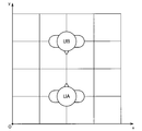
- FIG. 2 is an explanatory diagram for explaining an example of viewing experience while virtually sharing a spherical image with a plurality of users.
- the virtual dome-shaped screen VD20 is arranged in the virtual space, and the omnidirectional image is virtually projected as in the example shown in FIG.
- a plurality of avatars A21 to A23 each indicating a user are arranged inside the virtual dome-shaped screen VD20, and the position corresponding to each avatar (for example, the position of the head of each avatar).
- Virtual cameras VC21 to VC23 are arranged.
- the directions of the avatars A21 to A23 and the virtual cameras VC21 to VC23 may change according to the direction of each user.
- the virtual camera VC22 is arranged at the center position (preferred viewing position) of the virtual dome-shaped screen VD20, and the virtual camera VC21 and the virtual camera VC23 are arranged at other positions. For this reason, in a view image generated using the virtual camera VC21 and the virtual camera VC23 as a viewpoint, distortion or the like may occur, and it may be difficult for a user who is presented with the view image to view comfortably. .
- FIG. 3 is an explanatory diagram for explaining an example in which all avatars and all virtual cameras are arranged at suitable viewing positions.
- the avatar is arranged while maintaining the relative positional relationship between the users, and the view image generated from the viewpoint arranged at the preferred viewing position is presented to each user, thereby comfortably. While being viewable, it is possible to give a sufficient feeling that the spherical image is shared.
- the configuration and operation of the information processing system according to an embodiment of the present disclosure having such effects will be sequentially described.
- FIG. 4 is a block diagram illustrating a configuration example of an information processing system according to an embodiment of the present disclosure.
- the information processing system 9 includes an HMD 1, a distribution server 2, an avatar management server 3, a distributor terminal 4, and a communication network 5.
- the HMD 1 is an information processing device attached to the user.
- a user wearing the HMD 1 may be referred to as an HMD 1 wearing user.
- the wearing user of the HMD 1A is the user UA
- the wearing user of the HMD 1B is the user UB.
- the HMD 1 is connected to the communication network 5, receives an omnidirectional image (an example of a background image) from the distribution server 2, and receives information (user information) about users including other users from the avatar management server 3. Further, the HMD 1 transmits information regarding the user wearing the HMD 1 to the avatar management server 3.
- an omnidirectional image an example of a background image
- information user information
- the HMD 1 is a field of view generated with a preferred viewing position as a viewpoint based on an omnidirectional image (an example of a background image) arranged in a virtual space and an avatar arranged in the virtual space based on user information. Display an image. A more detailed configuration of the HMD 1 will be described later with reference to FIG.
- the distribution server 2 is an information processing apparatus having an image storage unit 22.
- the distribution server 2 distributes (sends) the omnidirectional image to the HMD 1A and the HMD 1B via the communication network 5.
- the distribution server 2 may distribute the omnidirectional image received from the distributor terminal 4 via the communication network 5 to the HMD 1 or distribute the omnidirectional image stored in the image storage unit 22 to the HMD 1. May be.
- the image storage unit 22 may store (accumulate) the omnidirectional image received from the distributor terminal 4 via the communication network 5 or may store the omnidirectional image prepared in advance.
- Good. 4 shows an example in which the distribution server 2 includes the image storage unit 22.
- the present embodiment is not limited to this example, and the image storage unit 22 is connected to, for example, another device connected to the communication network 5. It may be provided.
- the avatar management server 3 includes a user information storage unit 32.
- the avatar management server 3 manages user information based on information acquired from the HMD 1 and received from the HMD 1 via the communication network 5 and stores the user information in, for example, the user information storage unit 32.
- 4 illustrates an example in which the avatar management server 3 includes the user information storage unit 32.
- the present embodiment is not limited to the example, and the user information storage unit 32 may be connected to the communication network 5, for example. It may be provided in the apparatus.
- the avatar management server 3 transmits user information regarding users including users other than the user wearing the HMD 1 to the HMD 1 via the communication network 5.
- the avatar management server 3 may transmit real-time user information to the HMD 1 or may transmit past user information (history of user information) to the HMD 1.
- the real-time user information means information related to the user who is currently viewing and is not strictly limited to the user information at the current time, and is not limited to communication delay or processing of the avatar management server 3. It may include user information obtained after an accompanying delay or the like.
- the user information includes behavior information related to the behavior of the user wearing the HMD 1 acquired by the HMD 1, a relative position management coordinate system indicating a relative positional relationship (relative positional relationship) between users, and a message transmitted by the user. But you can.
- the user information may be stored in the user information storage unit 32 in time series. With such a configuration, the avatar management server 3 can transmit past user information to the HMD 1.
- the behavior information may include posture information regarding the posture of the user wearing the HMD 1.
- the posture information includes information on the head posture, arm, hand, foot posture, and facial expression of the wearing user.
- the behavior information may include information on the position movement of the user who wears the HMD 1.
- the avatar management server 3 manages the relative position management coordinate system based on, for example, information on the position movement of the user.
- the relative position management coordinate system is a coordinate system for managing the relative positional relationship between users independently of the virtual space managed by each HMD 1.
- the relative position management coordinate system includes not only the relative position between users but also information related to the relative orientation between users. As will be described later, the HMD 1 arranges the avatars of the respective users based on the relative position management coordinate system.
- FIG. 5 is an explanatory diagram showing a specific example of the relative position management coordinate system. As shown in FIG. 5, the position and orientation of the user UA and the position and orientation of the user UB are managed by the avatar management server 3 in the relative position management coordinate system.
- the avatar management server 3 may update the relative position management coordinate system in accordance with, for example, information on the position movement of the wearing user received from the HMD 1. Therefore, for example, the relative positional relationship between the user UA (first user) and the user UB (second user) can change according to the position movement of the user UA or the user UB.
- the avatar management server 3 may determine the initial position and initial orientation of each user in the relative position management coordinate system based on, for example, user information stored in the user information storage unit 32, that is, past user information. Good. Therefore, for example, the relative positional relationship between the user UA (first user) and the user UB (second user) can be specified based on past user information.
- the avatar management server 3 sets the position and orientation in the relative position management coordinate system when the user last viewed as the initial position and initial orientation of the user in the relative position management coordinate system. You may decide. Moreover, the avatar management server 3 may determine the average position and average direction of all past users as the initial position and initial direction of the user based on the past user information. With such a configuration, it is possible to determine the position and orientation that have been swelled by many users in the past as the initial position and the initial orientation.
- the avatar management server 3 may randomly determine the initial position and the initial orientation of each user in the relative position management coordinate system, or may be a predetermined predetermined value. It may be determined using the position and orientation.
- the message transmitted by the user may be, for example, text data or voice data.
- the text data may be converted into voice data by a voice synthesis technique, or the voice data may be converted into text data by a voice recognition technique.
- the message transmitted by the user is transmitted from the HMD 1 to the avatar management server 3 and then transmitted from the avatar management server 3 to the HMD 1 of the user to be transmitted. It is possible to send a message to all users or send a message to a specific user. Note that the message may be transmitted directly from the HMD 1 to another HMD 1 without going through the avatar management server 3.
- Distributor terminal 4 acquires the spherical image and transmits it to distribution server 2 via communication network 5.
- the distributor terminal 4 has an imaging unit, and may acquire an omnidirectional image based on the imaging by the imaging unit, or for imaging by an imaging device (not shown) connected to the distributor terminal 4.
- An omnidirectional image may be acquired based on this.
- the distributor terminal 4 may acquire an omnidirectional image by performing image processing such as stitching on the image obtained by imaging.
- the communication network 5 is a wired or wireless transmission path for information transmitted from a device or system connected to the communication network 5.
- the communication network 5 may include a public line network such as the Internet, a telephone line network, a satellite communication network, various LANs (Local Area Network) including Ethernet (registered trademark), a WAN (Wide Area Network), and the like.
- the communication network 5 may include a dedicated line network such as IP-VPN (Internet Protocol-Virtual Private Network).
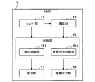
- FIG. 6 is a block diagram illustrating a configuration example of the HMD 1 according to the present embodiment.
- the HMD 1 is an information processing apparatus including a sensor unit 11, a communication unit 13, a control unit 15, a display unit 17, and a sound output unit 19.
- the sensor unit 11 acquires behavior information regarding the behavior of the user wearing the HMD 1 by sensing.
- the sensor unit 11 may include, for example, an acceleration sensor, a gyro sensor, a camera, a microphone, a geomagnetic sensor, a distance sensor, a force sensor, and the like.
- the sensor unit 11 may acquire posture information about the head posture (face orientation, head angle, etc.), arm, hand, foot posture, and facial expression of the wearing user as action information.
- the wearing user's facial expression can be acquired by a camera (an example of the sensor unit 11) disposed inside the HMD 1.
- the sensor part 11 may acquire a user's speech sound as action information.
- the sensor unit 11 may acquire information regarding the position movement of the user as behavior information.
- the behavior information is not limited to the example acquired by the sensor unit 11 included in the HMD 1, and may be acquired by an external sensor or an input device (such as a controller) connected to the HMD 1.
- information related to the position movement of the user may be acquired by a camera arranged outside the HMD 1 or an input device operated by the wearing user.
- posture information related to the postures of the user's arms, hands, and feet may be acquired by a camera or a distance measuring sensor disposed outside the HMD 1.
- the communication unit 13 is a communication interface that mediates communication between the HMD 1 and other devices.
- the communication unit 13 supports an arbitrary wireless communication protocol or wired communication protocol, and establishes a communication connection with another device, for example, via the communication network 5 described with reference to FIG. 4 or directly.
- the communication unit 13 transmits user information acquired by the sensor unit 11 or another sensor or input device connected to the HMD 1 to the avatar management server 3.
- the communication unit 13 receives an omnidirectional image from the distribution server 2.
- the communication unit 13 receives user information including information related to other users (users other than the user wearing the HMD 1) from the avatar management server 3.
- the user information received from the avatar management server 3 by the communication unit 13 may include behavior information of other users, a relative position management coordinate system, and messages transmitted by other users.
- the communication unit 13 may receive information from an external sensor or input device of the HMD 1 and transmit the received information to the avatar management server 3.
- the communication unit 13 may receive information related to the position movement of the user from an external sensor or input device and transmit the information to the avatar management server 3.
- the communication part 13 may receive the message which the user of HMD1 wants to transmit from an external input device, and may transmit to the avatar management server 3 or other HMD1.
- the control unit 15 controls the operation of each component of the HMD 1. Further, the control unit 15 also functions as a display control unit 151 and a sound output control unit 153 as shown in FIG.
- the display control unit 151 controls the display for the wearing user (first user) of the HMD 1, that is, the display of the display unit 17, based on the omnidirectional image (background image) received by the communication unit 13 and the user information. To do.
- the display control unit 151 arranges an omnidirectional image and an avatar of each user (an object indicating each user) in the virtual space, and a position (in accordance with the position of the wearing user (first user) in the virtual space ( For example, the field-of-view image is generated from the viewpoint arranged at the head position. Then, the display control unit 151 displays the view field image on the display unit 17.
- the display control unit 151 arranges the avatar of each user in the virtual space so as to maintain the relative positional relationship between the users in the virtual space based on the relative position management coordinate system received by the communication unit 13 from the avatar management server 3. .
- the avatar arranged by the display control unit 151 may include not only the avatars of other users but also the avatars of the wearing users. That is, the display control unit 151 may control the display based further on the avatar of the wearing user (first user). With such a configuration, the wearing user can also see his / her avatar, and for example, the feeling of immersion is improved.
- the display control unit 151 may control a user avatar corresponding to the user information based on the user information.
- the display control unit 151 may control the posture of each user's avatar based on the posture information of each user.
- the posture information of each user may include, for example, the above-described head posture (face orientation, head angle, etc.), arm, hand, and foot postures. With such a configuration, the user can obtain a stronger sense of sharing the omnidirectional image and the virtual space with other users.
- the display control unit 151 arranges the omnidirectional image in the virtual space with reference to the position of the wearing user in the virtual space (that is, the position of the wearing user's avatar).
- the arrangement of the omnidirectional image in the virtual space may be performed, for example, by arranging a virtual dome-shaped screen for projecting the omnidirectional image in the virtual space.
- FIG. 7 and 8 are explanatory diagrams showing an example of the arrangement of the avatar and the virtual dome-shaped screen in the virtual space.
- 7 illustrates a virtual space set by the display control unit 151 of the HMD 1A worn by the user UA
- FIG. 8 shows a virtual space set by the display control unit 151 of the HMD 1B worn by the user UB.
- the space is illustrated. That is, the wearing user (first user) in FIG. 7 is the user UA, and the wearing user (first user) in FIG. 8 is the user UB.
- the display control unit 151 of the HMD 1 ⁇ / b> A is based on the relative position management coordinate system described with reference to FIG. 5 so that the relative positional relationship between users in the virtual space is maintained.
- the avatar AA and the avatar AB of the user UB are arranged.
- the display control unit 151 of the HMD 1A arranges the omnidirectional image (that is, arranges the virtual dome-shaped screen VD1) based on the position of the user UA who is the wearing user (first user) (position of the avatar AA). To do).
- the display control unit 151 of the HMD 1A arranges the omnidirectional image so that the position of the virtual camera VC1 serving as the viewpoint becomes a predetermined preferred viewing position.
- the preferred viewing position is the center position of the virtual dome-shaped screen VD1
- the position of the virtual camera VC1 specified according to the position of the user UA in the virtual space for example, the head position of the avatar AA.
- a virtual dome-shaped screen VD1 is arranged so as to be in the center.
- the preferred viewing position is not limited to the center position of the virtual dome-shaped screen VD1, and the preferred viewing position may be set as appropriate.
- the display control unit 151 of the HMD 1B similarly maintains the relative positional relationship between users in the virtual space based on the relative position management coordinate system described with reference to FIG.
- the avatar AA of the user UA and the avatar AB of the user UB are arranged in the virtual space.
- the display control unit 151 of the HMD 1B arranges the omnidirectional image in the virtual space with the position of the user UB (the position of the avatar AB) being the wearing user (first user) as a reference (that is, the virtual dome-shaped screen). VD2 is placed).
- the display control unit 151 of the HMD 1B arranges the omnidirectional image in the virtual space so that the position of the virtual camera VC2 serving as the viewpoint becomes a predetermined preferred viewing position.
- the virtual dome-shaped screen VD2 is arranged in the virtual space so that the position of the virtual camera VC2 specified according to the position of the user UB in the virtual space (for example, the head position of the avatar AB) is the center.
- each user can view a view image generated with the preferred viewing position as a viewpoint, and can also view avatars of other users.
- the display control unit 151 may control the viewpoint direction (the direction of the virtual camera VC1) according to the direction of the wearing user (first user).
- the information on the orientation of the wearing user may be provided from the sensor unit 11 or may be provided from the avatar management server 3.
- FIG. 9 is an explanatory diagram showing an example of a visual field image V1 generated with the virtual camera VC1 shown in FIG. 7 as a viewpoint. That is, the view image V1 of FIG. 9 is displayed on the HMD 1A worn by the user UA.
- the field-of-view image V1 includes the avatar AB of the user UB and a part of the omnidirectional image E10. Moreover, as shown in FIG. 9, the visual field image V1 may include a part (hand) of the avatar AA of the user UA who is the wearing user.
- FIGS. 7 to 9 illustrate an example in which there is only one user other than the wearing user, the same applies when there are a plurality of other users.
- avatars of a plurality of other users may be arranged in the virtual space, and avatars of a plurality of other users may be included in the view field image.
- the display control unit 151 may arrange and display the avatar in the virtual space based on the past user information received from the avatar management server 3. For example, when the omnidirectional image is a moving image, it is not viewed at the same time, but the avatar is arranged in the virtual space based on the past user information having the same reproduction time in the moving image, and displayed. You may let them. With such a configuration, it is possible to display avatars of users who are not watching at the same time, so that even when there are few users watching at the same time, it is possible to obtain a sense of unity with other users.
- the display control unit 151 may control the display so that an avatar based on real-time user information (an avatar of a user viewing at the same time) and an avatar based on past user information are distinguished.
- the display control unit 151 may control the display so that an avatar based on real-time user information is emphasized.
- the display control unit 151 may emphasize the avatar based on real-time user information by increasing the transparency of the avatar based on past user information, or may apply an effect around the avatar based on real-time user information. By displaying, an avatar based on real-time user information may be emphasized.
- the display control unit 151 may control the display so that an avatar based on real-time user information is emphasized.
- the display control unit 151 may display distinguishable information (for example, an icon) in the vicinity of either or both of an avatar based on real-time user information and an avatar based on past user information.
- the display control unit 151 may perform display control related to communication between users. For example, the display control unit 151 may display a message transmitted by another user (second user). For example, the display control unit 151 may display the message at a position corresponding to the position of the user who sent the message (for example, near the face of the user's avatar).
- the display control unit 151 sends the other user (second user) who sent the message.
- the display may be controlled so that an avatar (hereinafter referred to as a message transmission avatar) is emphasized.
- the display control unit 151 may emphasize the message transmission avatar by increasing the transparency of the avatars other than the message transmission avatar, or may display the effect around the message transmission avatar to display the message transmission avatar. It may be emphasized. With such a configuration, for example, even when a large number of avatars are displayed, it is possible to easily recognize the avatar that transmitted the message. In particular, when avatars are displayed based on past user information as described above, a large number of avatars are likely to be displayed, and this highlighting is more effective.
- the sound output control unit 153 controls sound output by the sound output unit 19.
- the sound output control unit 153 may control the sound output unit 19 to sound output a message transmitted by another user (second user).
- the sound output control unit 153 may control the sound output by the sound output unit 19 so that the message can be heard from the position of the avatar of another user (second user) who has transmitted the message. With such a configuration, the wearing user can more strongly feel as if there is another user nearby.
- the display unit 17 is controlled by the display control unit 151 to perform display for the user who wears the HMD 1.
- the display unit 17 may be able to present different images for both eyes of the wearing user, for example, or may be able to visually recognize the virtual space as described above.
- the sound output unit 19 is controlled by the sound output control unit 153 to perform sound output.
- the sound output unit 19 may include, for example, a plurality of speakers, and the sound output unit 19 may be capable of outputting sound in a three-dimensional manner (stereo sound).
- FIG. 10 is a flowchart showing an operation example of the HMD 1 according to the present embodiment.
- the sensor unit 11 and the sensor connected to the HMD 1 acquire behavior information regarding the behavior of the wearing user by sensing (S102). Subsequently, the behavior information acquired by the communication unit 13 is transmitted to the avatar management server 3 (S104), and user information relating to users including other users is received from the avatar management server 3 (S106). Further, the communication unit 13 receives the omnidirectional image from the distribution server 2 (S108).
- the display control unit 151 arranges each user's avatar and the omnidirectional image in the virtual space based on the user information (S110).
- the display control unit 151 highlights the avatar (message transmission avatar) of the user who transmitted the message and displays the message on the display unit 17.
- the message may be acoustically output from the acoustic output unit 19 instead of or in addition to the display output by the display unit 17.
- the display control unit 151 displays all avatars evenly (S116). In step S114 and step S116, the display control unit 151 displays the field-of-view image generated from the viewpoint arranged at the preferred viewing position in the virtual space as described above.
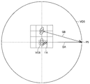
- the wearing user (first user) is a user UA, and the virtual camera VC3 is arranged according to the position of the user UA.
- the wearing user may want to point at the point P3 of the omnidirectional image projected on the dome-shaped screen VD3. .
- a virtual space set by the HMD 1B worn by the user UB when the control according to this modification is not performed will be considered.
- the wearing user is the user UB
- the virtual camera VC40 is arranged according to the position of the user UB.
- the avatar AA of the user UA is arranged according to the posture of the user UA
- the finger FA of the avatar AA is facing the direction DA as shown in FIG. Therefore, it is recognized from the user UB that the user UA is pointing at the point P40 of the omnidirectional image projected on the dome-shaped screen VD40, and the line of sight GB of the avatar AB of the user UB (that is, the line of sight of the user UB). Goes to point P40.
- FIG. 11 and FIG. 12 are compared, it can be seen that the user UB has looked at other points, not the point that the user UA originally wanted to point. Therefore, when it is determined that another user (second user) is pointing (an example of a predetermined condition), the display control unit 151 further determines the other The user's posture may be controlled. The same applies to the case where the whole celestial sphere image is pointed not only by a finger but also by an object or an arm.
- the display control unit 151 uses the other user's avatar to point to the position that the other user is pointing at based on the posture information of the other user and the arranged omnidirectional image.
- the posture of the avatar of the other user may be controlled.
- the position that the other user is about to point to can be specified by, for example, the intersection of the directivity and the dome-shaped screen in the virtual space set by the HMD worn by the other user.
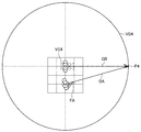
- FIG. 13 shows a control example of an avatar of another user of the display control unit 151 according to this modification described above.
- the wearing user is the user UB
- the virtual camera VC4 is arranged according to the position of the user UB.
- the line of sight GB of the avatar AB of the user UB goes to the point P4 of the dome-shaped screen VD4.
- the point P4 corresponds to the point P3 shown in FIG. 11, and the user UB can see the position in the omnidirectional image that the user UA wanted to point.
- FIG. 14 shows a virtual space set by the HMD 1A worn by the user UA based on the posture of the user UB in FIG. 13 when such control is not performed. That is, in FIG. 14, the wearing user is the user UA, and the virtual camera VC5 is arranged according to the position of the user UA. In the example of FIG. 14, the point P50 of the dome-shaped screen VD50 that the user UA is about to point to is different from the point P51 that is the tip of the line of sight GB of the avatar AB of the user UB.
- the display control unit 151 determines that another user (second user) is looking at a certain position of the omnidirectional image (an example of a predetermined condition).
- the posture of the other user may be controlled based on the omnidirectional image.
- the display control unit 151 according to this modification example is configured so that the line of sight GB of the avatar AB of the user UB is directed to the point P5 of the dome-shaped screen VD5 that the user UA is pointing to.
- the posture of AB may be controlled.
- FIG. 15 shows a virtual space set by the HMD 1A worn by the user UA as in FIG.
- the same position of the omnidirectional image can be shared between the users in the direction of the line of sight and the direction of the pointing.
- the point in the direction of the line of sight or the pointing direction is likely to be different between users as shown in FIG. Becomes more effective.
- the viewpoint in the virtual space is a position corresponding to the position of the wearing user (for example, the head position of the wearing user's avatar) has been described, but the present technology is not limited to such an example.
- the display control unit 151 may arrange the viewpoint at a predetermined overhead position in the virtual space. Such an example will be described as Modification 2 with reference to FIGS. 16 and 17.
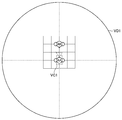
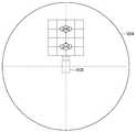
- FIG. 16 is an explanatory diagram showing a virtual space set in the present modification.
- the wearing user may be a user UA or a user UB.
- the virtual camera VC6 is disposed at an overhead position where the wearing user can also look down, and the display control unit 151 according to the present modification generates a bird's-eye view from the virtual camera VC6 as a viewpoint. 17 may be displayed.
- the dome-shaped screen VD6 is arranged so that the viewpoint position becomes the preferred viewing position.
- the viewpoint may be moved from a position corresponding to the position of the wearing user to an overhead view position in accordance with a user operation or the like.
- FIG. 17 is an explanatory diagram illustrating an example of the overhead image V2 displayed on the display unit 17 in the present modification.
- the bird's-eye view image V2 can include avatars AA to AE of a large number of users including the avatar of the wearing user, it is possible to have a bird's-eye view of the positional relationship among a plurality of avatars.
- the display control unit arranges the avatar in the virtual space, arranges the high-resolution image in the virtual space with the position of the wearing user as a reference so that the viewpoint becomes the preferential viewing position set in advance.
- a view field image may be generated from the viewpoint.
- the background image may be an image (computer graphics) rendered (generated) by a computer.
- the background image may be rendered on the basis of information on the position movement of the user.
- FIG. 18 is a block diagram illustrating an example of a hardware configuration of the information processing apparatus according to the present embodiment.
- the information processing apparatus 900 illustrated in FIG. 18 can realize, for example, the above-described HMD 1, distribution server 2, avatar management server 3, and distributor terminal 4.
- Information processing by the HMD 1, the distribution server 2, the avatar management server 3, and the distributor terminal 4 according to the present embodiment is realized by cooperation of software and hardware described below.
- the information processing apparatus 900 includes a CPU (Central Processing Unit) 901, a ROM (Read Only Memory) 902, a RAM (Random Access Memory) 903, and a host bus 904a.
- the information processing apparatus 900 includes a bridge 904, an external bus 904b, an interface 905, an input device 906, an output device 907, a storage device 908, a drive 909, a connection port 911, a communication device 913, and a sensor 915.
- the information processing apparatus 900 may include a processing circuit such as a DSP or an ASIC in place of or in addition to the CPU 901.
- the CPU 901 functions as an arithmetic processing unit and a control unit, and controls the overall operation in the information processing apparatus 900 according to various programs. Further, the CPU 901 may be a microprocessor.
- the ROM 902 stores programs used by the CPU 901, calculation parameters, and the like.
- the RAM 903 temporarily stores programs used in the execution of the CPU 901, parameters that change as appropriate during the execution, and the like.
- the CPU 901 can form the control unit 15, for example.
- the CPU 901, ROM 902, and RAM 903 are connected to each other by a host bus 904a including a CPU bus.
- the host bus 904 a is connected to an external bus 904 b such as a PCI (Peripheral Component Interconnect / Interface) bus via a bridge 904.
- an external bus 904 b such as a PCI (Peripheral Component Interconnect / Interface) bus
- PCI Peripheral Component Interconnect / Interface
- the host bus 904a, the bridge 904, and the external bus 904b do not necessarily have to be configured separately, and these functions may be mounted on one bus.
- the input device 906 is realized by a device in which information is input by the user, such as a mouse, a keyboard, a touch panel, a button, a microphone, a switch, and a lever.
- the input device 906 may be, for example, a remote control device using infrared rays or other radio waves, or may be an external connection device such as a mobile phone or a PDA that supports the operation of the information processing device 900.
- the input device 906 may include, for example, an input control circuit that generates an input signal based on information input by the user using the above-described input means and outputs the input signal to the CPU 901.
- a user of the information processing apparatus 900 can input various data and instruct a processing operation to the information processing apparatus 900 by operating the input device 906.
- the output device 907 is formed of a device that can notify the user of the acquired information visually or audibly. Examples of such devices include CRT display devices, liquid crystal display devices, plasma display devices, EL display devices, display devices such as lamps, audio output devices such as speakers and headphones, printer devices, and the like.
- the output device 907 outputs results obtained by various processes performed by the information processing device 900. Specifically, the display device visually displays results obtained by various processes performed by the information processing device 900 in various formats such as text, images, tables, and graphs.
- the audio output device converts an audio signal composed of reproduced audio data, acoustic data, and the like into an analog signal and outputs it aurally.
- the output device 907 can form the display unit 17 and the sound output unit 19, for example.
- the storage device 908 is a data storage device formed as an example of a storage unit of the information processing device 900.
- the storage apparatus 908 is realized by, for example, a magnetic storage device such as an HDD, a semiconductor storage device, an optical storage device, a magneto-optical storage device, or the like.
- the storage device 908 may include a storage medium, a recording device that records data on the storage medium, a reading device that reads data from the storage medium, a deletion device that deletes data recorded on the storage medium, and the like.
- the storage device 908 stores programs executed by the CPU 901, various data, various data acquired from the outside, and the like.
- the storage device 908 can form, for example, the image storage unit 22 and the user information storage unit 32.
- the drive 909 is a storage medium reader / writer, and is built in or externally attached to the information processing apparatus 900.
- the drive 909 reads information recorded on a removable storage medium such as a magnetic disk, an optical disk, a magneto-optical disk, or a semiconductor memory, and outputs the information to the RAM 903.
- the drive 909 can also write information to a removable storage medium.
- connection port 911 is an interface connected to an external device, and is a connection port with an external device capable of transmitting data by USB (Universal Serial Bus), for example.
- USB Universal Serial Bus
- the communication device 913 is a communication interface formed by a communication device or the like for connecting to the network 920, for example.
- the communication device 913 is, for example, a communication card for wired or wireless LAN (Local Area Network), LTE (Long Term Evolution), Bluetooth (registered trademark), or WUSB (Wireless USB).
- the communication device 913 may be a router for optical communication, a router for ADSL (Asymmetric Digital Subscriber Line), a modem for various communication, or the like.
- the communication device 913 can transmit and receive signals and the like according to a predetermined protocol such as TCP / IP, for example, with the Internet and other communication devices.
- the communication device 913 can form the communication unit 13, for example.
- the sensor 915 is various sensors such as an acceleration sensor, a gyro sensor, a geomagnetic sensor, an optical sensor, a sound sensor, a distance measuring sensor, and a force sensor.
- the sensor 915 acquires information on the state of the information processing apparatus 900 itself, such as the posture and movement speed of the information processing apparatus 900, and information on the surrounding environment of the information processing apparatus 900, such as brightness and noise around the information processing apparatus 900.
- Sensor 915 may also include a GPS sensor that receives GPS signals and measures the latitude, longitude, and altitude of the device.
- the sensor 915 can form the sensor unit 11, for example.
- the network 920 is a wired or wireless transmission path for information transmitted from a device connected to the network 920.
- the network 920 may include a public line network such as the Internet, a telephone line network, and a satellite communication network, various LANs including the Ethernet (registered trademark), a wide area network (WAN), and the like.
- the network 920 may include a dedicated line network such as an IP-VPN (Internet Protocol-Virtual Private Network).
- IP-VPN Internet Protocol-Virtual Private Network
- each of the above components may be realized using a general-purpose member, or may be realized by hardware specialized for the function of each component. Therefore, it is possible to change the hardware configuration to be used as appropriate according to the technical level at the time of carrying out this embodiment.
- a computer program for realizing each function of the information processing apparatus 900 according to the present embodiment as described above can be produced and mounted on a PC or the like.
- a computer-readable recording medium storing such a computer program can be provided.
- the recording medium is, for example, a magnetic disk, an optical disk, a magneto-optical disk, a flash memory, or the like.
- the above computer program may be distributed via a network, for example, without using a recording medium.
- the present technology is not limited to the example.
- a function of generating an image to be displayed on a display unit included in another device can be understood as a function as a display control unit.
- an information processing device for example, the distribution server 2 or the avatar management server 3 shown in FIG. 4 connected to a display device including a display unit via a communication network has a function as the display control unit described above. May be.
- an image including a background image and an avatar may be generated by the display control unit of the information processing apparatus and transmitted to the display apparatus, and the image received by the display apparatus may be displayed.
- the information processing apparatus connected to the display apparatus including the display unit via the communication network and the display apparatus may be provided with the functions as the display control unit described above in a distributed manner.
- the information processing apparatus may control the display of the display device by arranging avatars and omnidirectional images in the virtual space.
- the display device may receive the virtual space information and generate a view field image at a viewpoint according to the sensed user orientation.
- the display unit need not be an HMD.
- the display unit may be a display held by the user, a display installed, or a screen (including a dome-shaped screen) on which an image is projected by a projector.
- the display or the projector may have the function as the display control unit described above, or the information processing apparatus connected to the display or the projector, or the information processing apparatus connected via the communication network.
- Another information processing apparatus may have the function as the display control unit described above.
- An information processing apparatus comprising: a display control unit configured to control display for the first user based on an object related to the second user arranged in a virtual space.
- the display control unit generates a visual field image at a viewpoint arranged at a position corresponding to the position of the first user in the virtual space, and displays the visual field image.
- the background image is arranged so that the position of the viewpoint is a predetermined preferred viewing position.
- the information processing apparatus according to any one of (7) to (7).
- the information processing apparatus according to any one of (1) to (8), wherein the display control unit controls the display based further on an object related to the first user.
- the information processing apparatus controls an object related to a user corresponding to the user information based on the user information.
- the user information includes posture information regarding the posture of each user,
- the information processing apparatus controls an attitude of an object related to a user corresponding to the attitude information based on the attitude information.
- the display control unit when the posture information related to the posture of the second user satisfies a predetermined condition, based on the background image arranged in the virtual space, the posture of the object related to the second user The information processing apparatus according to (11), wherein the information processing apparatus is controlled. (13) The information processing apparatus according to any one of (10) to (12), wherein the display control unit displays an object based on the past user information. (14) The information processing apparatus according to (13), wherein the display control unit controls the display so that an object based on the real-time user information and an object based on the past user information are distinguished. (15) The information processing apparatus according to (13) or (14), wherein the relative positional relationship between the first user and the second user is specified based on the past user information.
- the display control unit generates an overhead image from a viewpoint arranged at a predetermined overhead position in the virtual space, and displays the overhead image. Processing equipment.
- the display control unit controls display of an apparatus worn by the first user.
- the background image arranged in the virtual space with reference to the position of the first user in the virtual space, and the relative positional relationship between the first user and the second user in the virtual space are maintained.
- An information processing method comprising: a processor controlling a display for the first user based on an object relating to the second user arranged in a virtual space. (20) On the computer, The background image arranged in the virtual space with reference to the position of the first user in the virtual space, and the relative positional relationship between the first user and the second user in the virtual space are maintained. A program for realizing a function of controlling display for the first user based on an object related to the second user arranged in a virtual space.
Landscapes
- Engineering & Computer Science (AREA)
- Theoretical Computer Science (AREA)
- General Engineering & Computer Science (AREA)
- Physics & Mathematics (AREA)
- General Physics & Mathematics (AREA)
- Human Computer Interaction (AREA)
- Multimedia (AREA)
- Signal Processing (AREA)
- Computing Systems (AREA)
- Geometry (AREA)
- Computer Graphics (AREA)
- Acoustics & Sound (AREA)
- Health & Medical Sciences (AREA)
- Audiology, Speech & Language Pathology (AREA)
- General Health & Medical Sciences (AREA)
- User Interface Of Digital Computer (AREA)
- Processing Or Creating Images (AREA)
- Testing, Inspecting, Measuring Of Stereoscopic Televisions And Televisions (AREA)
Abstract
Description
<<1.背景>>
<<2.構成>>
<2-1.全体構成>
<2-2.HMDの構成>
<<3.動作>>
<<4.変形例>>
<4-1.変形例1>
<4-2.変形例2>
<4-3.変形例3>
<<5.ハードウェア構成例>>
<<6.むすび>>
本開示の一実施形態に係る情報処理システムについて説明する前に、まず本実施形態による情報処理システムの創作に至った背景を説明する。
<2-1.全体構成>
まず、図4を参照して本開示の一実施形態に係る情報処理システムの全体構成を説明する。図4は、本開示の一実施形態に係る情報処理システムの構成例を示すブロック図である。
以上、本実施形態に係る情報処理システム9の全体構成を説明した。続いて、図6を参照して、情報処理システム9が有するHMD1の構成について説明する。図6は、本実施形態に係るHMD1の構成例を示すブロック図である。
以上、本実施形態に係る情報処理システム9、及びHMD1の構成例について説明した。続いて、本実施形態に係るHMD1の動作について図10を参照して説明する。図10は本実施形態に係るHMD1の動作例を示すフローチャート図である。
以上、本開示の一実施形態を説明した。以下では、本実施形態の幾つかの変形例を説明する。なお、以下に説明する各変形例は、単独で本実施形態に適用されてもよいし、組み合わせで本実施形態に適用されてもよい。また、各変形例は、本実施形態で説明した構成に代えて適用されてもよいし、本実施形態で説明した構成に対して追加的に適用されてもよい。
上記実施形態では、表示制御部151がユーザのアバタの姿勢を、当該ユーザの姿勢情報に基づいて制御する例を説明したが、本技術は係る例に限定されない。例えば、表示制御部151は、他のユーザ(第2のユーザ)の姿勢に関する姿勢情報が所定の条件を満たす場合に、仮想空間に配置された全天球画像にさらに基づいて、当該他のユーザのアバタの姿勢を制御してもよい。係る例について、変形例1として、図11~図15を参照して説明する。図11~図15は変形例1を説明するための説明図である。
また、上記実施形態では、仮想空間における視点は装着ユーザの位置に応じた位置(例えば装着ユーザのアバタの頭部位置)である例を説明したが、本技術は係る例に限定されない。例えば、表示制御部151は、視点を仮想空間における所定の俯瞰位置に配置してもよい。係る例について、図16、図17を参照して変形例2として説明する。
上記実施形態では、背景画像として全天球画像が用いられる例を説明したが、本技術は係る例に限定されない。背景画像としては多様な画像が用いられ得る。例えば、所謂4K画像や8K画像のような高い解像度を有する高解像度画像を背景画像とすることも可能である。
以上、本開示の実施形態を説明した。最後に、図18を参照して、本実施形態に係る情報処理装置のハードウェア構成について説明する。図18は、本実施形態に係る情報処理装置のハードウェア構成の一例を示すブロック図である。なお、図18に示す情報処理装置900は、例えば、上述したHMD1、配信サーバ2、アバタ管理サーバ3、配信者端末4を実現し得る。本実施形態に係るHMD1、配信サーバ2、アバタ管理サーバ3、配信者端末4による情報処理は、ソフトウェアと、以下に説明するハードウェアとの協働により実現される。
以上説明したように、本開示の実施形態によれば、画像を、他のユーザと仮想的に共有しながら視聴することが可能である。
(1)
仮想空間における第1のユーザの位置を基準として前記仮想空間に配置された背景画像、及び前記仮想空間における前記第1のユーザと第2のユーザとの間の相対位置関係を維持するように前記仮想空間に配置された前記第2のユーザに関するオブジェクトに基づいて、前記第1のユーザ用の表示を制御する表示制御部を備える、情報処理装置。
(2)
前記表示制御部は、前記仮想空間における前記第1のユーザの位置に応じた位置に配置された視点で視界画像を生成し、前記視界画像を表示させる、前記(1)に記載の情報処理装置。
(3)
前記背景画像は、前記視点の位置が予め定められた好適視聴位置となるように配置される、前記(2)に記載の情報処理装置。
(4)
前記表示制御部は、前記第1のユーザの向きに応じて、前記視点の向きを制御する、前記(2)または(3)に記載の情報処理装置。
(5)
前記表示制御部は、前記第2のユーザにより発信されるメッセージを表示させる、前記(1)~(4)のいずれか一項に記載の情報処理装置。
(6)
前記第2のユーザにより発信されるメッセージを音響出力させる音響出力制御部をさらに備える、前記(1)~(5)のいずれか一項に記載の情報処理装置。
(7)
前記音響出力制御部は、前記第2のユーザに関するオブジェクトの位置から前記メッセージが聞こえるように音響出力を制御する、前記(6)に記載の情報処理装置。
(8)
前記表示制御部は、前記第2のユーザが前記第1のユーザに対して前記メッセージを発信した場合に、前記第2のユーザに関するオブジェクトが強調されるように前記表示を制御する、前記(5)~(7)のいずれか一項に記載の情報処理装置。
(9)
前記表示制御部は、前記第1のユーザに関するオブジェクトにさらに基づいて、前記表示を制御する、前記(1)~(8)のいずれか一項に記載の情報処理装置。
(10)
前記表示制御部は、ユーザ情報に基づいて、当該ユーザ情報に対応したユーザに関するオブジェクトを制御する、前記(1)~(9)のいずれか一項に記載の情報処理装置。
(11)
前記ユーザ情報は、前記各ユーザの姿勢に関する姿勢情報を含み、
前記表示制御部は、前記姿勢情報に基づいて、当該姿勢情報に対応したユーザに関するオブジェクトの姿勢を制御する、前記(10)に記載の情報処理装置。
(12)
前記表示制御部は、前記第2のユーザの姿勢に関する前記姿勢情報が所定の条件を満たす場合に、前記仮想空間に配置された前記背景画像にさらに基づいて、前記第2のユーザに関するオブジェクトの姿勢を制御する、前記(11)に記載の情報処理装置。
(13)
前記表示制御部は、過去の前記ユーザ情報に基づくオブジェクトを表示させる、前記(10)~(12)のいずれか一項に記載の情報処理装置。
(14)
前記表示制御部は、リアルタイムの前記ユーザ情報に基づくオブジェクトと、前記過去の前記ユーザ情報に基づくオブジェクトとが区別されるように、前記表示を制御する、前記(13)に記載の情報処理装置。
(15)
前記第1のユーザと第2のユーザとの間の前記相対位置関係は、前記過去の前記ユーザ情報に基づいて特定される、前記(13)または(14)に記載の情報処理装置。
(16)
前記第1のユーザと第2のユーザとの間の前記相対位置関係は、前記第1のユーザまたは前記第2のユーザの位置移動に応じて変化する、前記(1)~(15)のいずれか一項に記載の情報処理装置。
(17)
前記表示制御部は、前記仮想空間における所定の俯瞰位置に配置された視点で俯瞰画像を生成し、前記俯瞰画像を表示させる、前記(1)~(16)のいずれか一項に記載の情報処理装置。
(18)
前記表示制御部は、前記第1のユーザにより装着された装置の表示を制御する、前記(1)~(17)のいずれか一項に記載の情報処理装置。
(19)
仮想空間における第1のユーザの位置を基準として前記仮想空間に配置された背景画像、及び前記仮想空間における前記第1のユーザと第2のユーザとの間の相対位置関係を維持するように前記仮想空間に配置された前記第2のユーザに関するオブジェクトに基づいて、前記第1のユーザ用の表示をプロセッサが制御すること、を含む情報処理方法。
(20)
コンピュータに、
仮想空間における第1のユーザの位置を基準として前記仮想空間に配置された背景画像、及び前記仮想空間における前記第1のユーザと第2のユーザとの間の相対位置関係を維持するように前記仮想空間に配置された前記第2のユーザに関するオブジェクトに基づいて、前記第1のユーザ用の表示を制御する機能を実現させるための、プログラム。
2 配信サーバ
3 アバタ管理サーバ
4 配信者端末
5 通信網
9 情報処理システム
11 センサ部
13 通信部
15 制御部
17 表示部
19 音響出力部
22 画像記憶部
32 ユーザ情報記憶部
151 表示制御部
153 音響出力制御部
Claims (20)
- 仮想空間における第1のユーザの位置を基準として前記仮想空間に配置された背景画像、及び前記仮想空間における前記第1のユーザと第2のユーザとの間の相対位置関係を維持するように前記仮想空間に配置された前記第2のユーザに関するオブジェクトに基づいて、前記第1のユーザ用の表示を制御する表示制御部を備える、情報処理装置。
- 前記表示制御部は、前記仮想空間における前記第1のユーザの位置に応じた位置に配置された視点で視界画像を生成し、前記視界画像を表示させる、請求項1に記載の情報処理装置。
- 前記背景画像は、前記視点の位置が予め定められた好適視聴位置となるように配置される、請求項2に記載の情報処理装置。
- 前記表示制御部は、前記第1のユーザの向きに応じて、前記視点の向きを制御する、請求項2に記載の情報処理装置。
- 前記表示制御部は、前記第2のユーザにより発信されるメッセージを表示させる、請求項1に記載の情報処理装置。
- 前記第2のユーザにより発信されるメッセージを音響出力させる音響出力制御部をさらに備える、請求項1に記載の情報処理装置。
- 前記音響出力制御部は、前記第2のユーザに関するオブジェクトの位置から前記メッセージが聞こえるように音響出力を制御する、請求項6に記載の情報処理装置。
- 前記表示制御部は、前記第2のユーザが前記第1のユーザに対して前記メッセージを発信した場合に、前記第2のユーザに関するオブジェクトが強調されるように前記表示を制御する、請求項5に記載の情報処理装置。
- 前記表示制御部は、前記第1のユーザに関するオブジェクトにさらに基づいて、前記表示を制御する、請求項1に記載の情報処理装置。
- 前記表示制御部は、ユーザ情報に基づいて、当該ユーザ情報に対応したユーザに関するオブジェクトを制御する、請求項1に記載の情報処理装置。
- 前記ユーザ情報は、前記各ユーザの姿勢に関する姿勢情報を含み、
前記表示制御部は、前記姿勢情報に基づいて、当該姿勢情報に対応したユーザに関するオブジェクトの姿勢を制御する、請求項10に記載の情報処理装置。 - 前記表示制御部は、前記第2のユーザの姿勢に関する前記姿勢情報が所定の条件を満たす場合に、前記仮想空間に配置された前記背景画像にさらに基づいて、前記第2のユーザに関するオブジェクトの姿勢を制御する、請求項11に記載の情報処理装置。
- 前記表示制御部は、過去の前記ユーザ情報に基づくオブジェクトを表示させる、請求項10に記載の情報処理装置。
- 前記表示制御部は、リアルタイムの前記ユーザ情報に基づくオブジェクトと、前記過去の前記ユーザ情報に基づくオブジェクトとが区別されるように、前記表示を制御する、請求項13に記載の情報処理装置。
- 前記第1のユーザと第2のユーザとの間の前記相対位置関係は、前記過去の前記ユーザ情報に基づいて特定される、請求項13に記載の情報処理装置。
- 前記第1のユーザと第2のユーザとの間の前記相対位置関係は、前記第1のユーザまたは前記第2のユーザの位置移動に応じて変化する、請求項1に記載の情報処理装置。
- 前記表示制御部は、前記仮想空間における所定の俯瞰位置に配置された視点で俯瞰画像を生成し、前記俯瞰画像を表示させる、請求項1に記載の情報処理装置。
- 前記表示制御部は、前記第1のユーザにより装着された装置の表示を制御する、請求項1に記載の情報処理装置。
- 仮想空間における第1のユーザの位置を基準として前記仮想空間に配置された背景画像、及び前記仮想空間における前記第1のユーザと第2のユーザとの間の相対位置関係を維持するように前記仮想空間に配置された前記第2のユーザに関するオブジェクトに基づいて、前記第1のユーザ用の表示をプロセッサが制御すること、を含む情報処理方法。
- コンピュータに、
仮想空間における第1のユーザの位置を基準として前記仮想空間に配置された背景画像、及び前記仮想空間における前記第1のユーザと第2のユーザとの間の相対位置関係を維持するように前記仮想空間に配置された前記第2のユーザに関するオブジェクトに基づいて、前記第1のユーザ用の表示を制御する機能を実現させるための、プログラム。
Priority Applications (4)
| Application Number | Priority Date | Filing Date | Title |
|---|---|---|---|
| US16/606,391 US11361497B2 (en) | 2017-05-24 | 2018-03-30 | Information processing device and information processing method |
| JP2019519500A JPWO2018216355A1 (ja) | 2017-05-24 | 2018-03-30 | 情報処理装置、情報処理方法、及びプログラム |
| EP18806186.5A EP3633497A4 (en) | 2017-05-24 | 2018-03-30 | INFORMATION PROCESSING DEVICE, INFORMATION PROCESSING PROCESS AND PROGRAM |
| CN201880032589.XA CN110637274B (zh) | 2017-05-24 | 2018-03-30 | 信息处理设备、信息处理方法以及程序 |
Applications Claiming Priority (2)
| Application Number | Priority Date | Filing Date | Title |
|---|---|---|---|
| JP2017102868 | 2017-05-24 | ||
| JP2017-102868 | 2017-05-24 |
Publications (1)
| Publication Number | Publication Date |
|---|---|
| WO2018216355A1 true WO2018216355A1 (ja) | 2018-11-29 |
Family
ID=64396744
Family Applications (1)
| Application Number | Title | Priority Date | Filing Date |
|---|---|---|---|
| PCT/JP2018/013713 WO2018216355A1 (ja) | 2017-05-24 | 2018-03-30 | 情報処理装置、情報処理方法、及びプログラム |
Country Status (5)
| Country | Link |
|---|---|
| US (1) | US11361497B2 (ja) |
| EP (1) | EP3633497A4 (ja) |
| JP (1) | JPWO2018216355A1 (ja) |
| CN (1) | CN110637274B (ja) |
| WO (1) | WO2018216355A1 (ja) |
Cited By (2)
| Publication number | Priority date | Publication date | Assignee | Title |
|---|---|---|---|---|
| WO2021049356A1 (ja) * | 2019-09-13 | 2021-03-18 | ソニー株式会社 | 再生装置、再生方法、及び記録媒体 |
| WO2024004398A1 (ja) * | 2022-06-29 | 2024-01-04 | ソニーグループ株式会社 | 情報処理装置、プログラム、及び情報処理システム |
Families Citing this family (4)
| Publication number | Priority date | Publication date | Assignee | Title |
|---|---|---|---|---|
| US11756259B2 (en) * | 2019-04-17 | 2023-09-12 | Rakuten Group, Inc. | Display controlling device, display controlling method, program, and non-transitory computer-readable information recording medium |
| KR102676846B1 (ko) * | 2021-12-31 | 2024-06-20 | 경북대학교 산학협력단 | 메타버스 환경에서 돔 디스플레이 운영 방법 |
| DE102022201351A1 (de) * | 2022-02-09 | 2023-08-10 | Robert Bosch Gesellschaft mit beschränkter Haftung | Verfahren zu einer Nutzeraktivitätserkennung für Datenbrillen und Datenbrille |
| US11700354B1 (en) * | 2022-07-21 | 2023-07-11 | Katmai Tech Inc. | Resituating avatars in a virtual environment |
Citations (7)
| Publication number | Priority date | Publication date | Assignee | Title |
|---|---|---|---|---|
| JP2006025281A (ja) * | 2004-07-09 | 2006-01-26 | Hitachi Ltd | 情報源選択システム、および方法 |
| JP2007188310A (ja) * | 2006-01-13 | 2007-07-26 | Nec Biglobe Ltd | 仮想チャット空間システム、端末、方法及びプログラム |
| JP2009140197A (ja) * | 2007-12-06 | 2009-06-25 | Internatl Business Mach Corp <Ibm> | 仮想空間における行動履歴の効率的記録方法および再生方法 |
| JP2014195599A (ja) * | 2013-03-29 | 2014-10-16 | 任天堂株式会社 | プログラム、情報処理装置、情報処理方法及び情報処理システム |
| JP2016105593A (ja) | 2014-11-26 | 2016-06-09 | ソニー株式会社 | ライブ選択的適応帯域幅 |
| JP2017073042A (ja) * | 2015-10-08 | 2017-04-13 | 富士通株式会社 | 画像生成システム、画像生成プログラム及び画像生成方法 |
| JP2017076202A (ja) * | 2015-10-13 | 2017-04-20 | 富士通株式会社 | 反応出力システム、反応出力プログラム、反応出力方法 |
Family Cites Families (22)
| Publication number | Priority date | Publication date | Assignee | Title |
|---|---|---|---|---|
| SE503067C2 (sv) | 1994-07-06 | 1996-03-18 | Rolf Blomdahl | Styrdon för datorer eller industriella processer |
| US7925703B2 (en) * | 2000-12-26 | 2011-04-12 | Numedeon, Inc. | Graphical interactive interface for immersive online communities |
| JP5226961B2 (ja) * | 2007-02-28 | 2013-07-03 | 株式会社スクウェア・エニックス | ゲーム装置、キャラクタ及び仮想カメラの制御方法、並びにプログラム及び記録媒体 |
| WO2012165978A1 (en) * | 2011-05-30 | 2012-12-06 | Auckland Uniservices Limited | Interactive gaming system |
| JP5927966B2 (ja) * | 2012-02-14 | 2016-06-01 | ソニー株式会社 | 表示制御装置、表示制御方法、及びプログラム |
| JP6056178B2 (ja) * | 2012-04-11 | 2017-01-11 | ソニー株式会社 | 情報処理装置、表示制御方法及びプログラム |
| US10969924B2 (en) * | 2013-03-08 | 2021-04-06 | Sony Corporation | Information processing apparatus, method, and non-transitory computer readable medium that controls a representation of a user object in a virtual space |
| JP6548203B2 (ja) * | 2013-03-18 | 2019-07-24 | 任天堂株式会社 | 情報処理プログラム、情報処理装置、情報処理システム、および、パノラマ動画表示方法 |
| US9940897B2 (en) * | 2013-05-24 | 2018-04-10 | Awe Company Limited | Systems and methods for a shared mixed reality experience |
| US9830679B2 (en) | 2014-03-25 | 2017-11-28 | Google Llc | Shared virtual reality |
| US9818225B2 (en) * | 2014-09-30 | 2017-11-14 | Sony Interactive Entertainment Inc. | Synchronizing multiple head-mounted displays to a unified space and correlating movement of objects in the unified space |
| EP3219098B1 (en) * | 2014-11-14 | 2021-10-06 | PCMS Holdings, Inc. | System and method for 3d telepresence |
| US10684485B2 (en) * | 2015-03-06 | 2020-06-16 | Sony Interactive Entertainment Inc. | Tracking system for head mounted display |
| JP2017027477A (ja) * | 2015-07-24 | 2017-02-02 | 株式会社オプティム | 3次元出力サーバ、3次元出力方法及び3次元出力サーバ用プログラム。 |
| CN108028964B (zh) * | 2015-09-14 | 2021-06-29 | 索尼公司 | 信息处理装置以及信息处理方法 |
| KR20170051013A (ko) * | 2015-11-02 | 2017-05-11 | 엘지전자 주식회사 | 테더링 형 hmd 및 그 hmd의 제어 방법 |
| JP5996814B1 (ja) * | 2016-02-08 | 2016-09-21 | 株式会社コロプラ | 仮想空間の画像をヘッドマウントディスプレイに提供する方法及びプログラム |
| JP6754678B2 (ja) * | 2016-11-18 | 2020-09-16 | 株式会社バンダイナムコエンターテインメント | シミュレーションシステム及びプログラム |
| JP6298523B1 (ja) * | 2016-12-26 | 2018-03-20 | 株式会社コロプラ | 仮想空間を介して通信するためにコンピュータによって実行される方法、当該方法をコンピュータに実行させるためのプログラム、およびコンピュータ装置 |
| JP6306765B1 (ja) * | 2017-02-27 | 2018-04-04 | 株式会社コロプラ | 仮想空間を移動するためにコンピュータで実行される方法、当該方法をコンピュータに実行させるプログラムおよび情報処理装置 |
| JP6298558B1 (ja) * | 2017-05-11 | 2018-03-20 | 株式会社コロプラ | 仮想空間を提供するための方法、および当該方法をコンピュータに実行させるためのプログラム、および当該プログラムを実行するための情報処理装置 |
| JP6276882B1 (ja) * | 2017-05-19 | 2018-02-07 | 株式会社コロプラ | 情報処理方法、装置、および当該情報処理方法をコンピュータに実行させるためのプログラム |
-
2018
- 2018-03-30 JP JP2019519500A patent/JPWO2018216355A1/ja active Pending
- 2018-03-30 WO PCT/JP2018/013713 patent/WO2018216355A1/ja active Application Filing
- 2018-03-30 CN CN201880032589.XA patent/CN110637274B/zh active Active
- 2018-03-30 EP EP18806186.5A patent/EP3633497A4/en active Pending
- 2018-03-30 US US16/606,391 patent/US11361497B2/en active Active
Patent Citations (7)
| Publication number | Priority date | Publication date | Assignee | Title |
|---|---|---|---|---|
| JP2006025281A (ja) * | 2004-07-09 | 2006-01-26 | Hitachi Ltd | 情報源選択システム、および方法 |
| JP2007188310A (ja) * | 2006-01-13 | 2007-07-26 | Nec Biglobe Ltd | 仮想チャット空間システム、端末、方法及びプログラム |
| JP2009140197A (ja) * | 2007-12-06 | 2009-06-25 | Internatl Business Mach Corp <Ibm> | 仮想空間における行動履歴の効率的記録方法および再生方法 |
| JP2014195599A (ja) * | 2013-03-29 | 2014-10-16 | 任天堂株式会社 | プログラム、情報処理装置、情報処理方法及び情報処理システム |
| JP2016105593A (ja) | 2014-11-26 | 2016-06-09 | ソニー株式会社 | ライブ選択的適応帯域幅 |
| JP2017073042A (ja) * | 2015-10-08 | 2017-04-13 | 富士通株式会社 | 画像生成システム、画像生成プログラム及び画像生成方法 |
| JP2017076202A (ja) * | 2015-10-13 | 2017-04-20 | 富士通株式会社 | 反応出力システム、反応出力プログラム、反応出力方法 |
Non-Patent Citations (1)
| Title |
|---|
| See also references of EP3633497A4 |
Cited By (4)
| Publication number | Priority date | Publication date | Assignee | Title |
|---|---|---|---|---|
| WO2021049356A1 (ja) * | 2019-09-13 | 2021-03-18 | ソニー株式会社 | 再生装置、再生方法、及び記録媒体 |
| CN114342367A (zh) * | 2019-09-13 | 2022-04-12 | 索尼集团公司 | 再现装置、再现方法和记录介质 |
| US12063344B2 (en) | 2019-09-13 | 2024-08-13 | Sony Group Corporation | Reproduction device, reproduction method, and recording medium |
| WO2024004398A1 (ja) * | 2022-06-29 | 2024-01-04 | ソニーグループ株式会社 | 情報処理装置、プログラム、及び情報処理システム |
Also Published As
| Publication number | Publication date |
|---|---|
| EP3633497A1 (en) | 2020-04-08 |
| EP3633497A4 (en) | 2020-04-08 |
| JPWO2018216355A1 (ja) | 2020-05-21 |
| US11361497B2 (en) | 2022-06-14 |
| US20210110596A1 (en) | 2021-04-15 |
| CN110637274A (zh) | 2019-12-31 |
| CN110637274B (zh) | 2022-05-03 |
Similar Documents
| Publication | Publication Date | Title |
|---|---|---|
| WO2018216355A1 (ja) | 情報処理装置、情報処理方法、及びプログラム | |
| US11250636B2 (en) | Information processing device, information processing method, and program | |
| JP6822410B2 (ja) | 情報処理システム及び情報処理方法 | |
| JPWO2019013016A1 (ja) | 情報処理装置、情報処理方法、及びプログラム | |
| CN112533017B (zh) | 直播方法、装置、终端及存储介质 | |
| WO2018163637A1 (ja) | 情報処理装置、情報処理方法及び記録媒体 | |
| JPWO2018150831A1 (ja) | 情報処理装置、情報処理方法及び記録媒体 | |
| WO2017221492A1 (ja) | 情報処理装置、情報処理方法、及びプログラム | |
| JP2020120336A (ja) | プログラム、方法、および情報処理装置 | |
| US11806621B2 (en) | Gaming with earpiece 3D audio | |
| KR20180017736A (ko) | Hmd 및 그 hmd의 제어 방법 | |
| JPWO2019069575A1 (ja) | 情報処理装置、情報処理方法及びプログラム | |
| JPWO2017064926A1 (ja) | 情報処理装置及び情報処理方法 | |
| JP2023551665A (ja) | 仮想位置を指示する実世界ビーコン | |
| WO2019142621A1 (ja) | 情報処理装置、情報処理方法、及びプログラム | |
| US20240153226A1 (en) | Information processing apparatus, information processing method, and program | |
| JP6250779B1 (ja) | 仮想空間を介して通信するためにコンピュータで実行される方法、当該方法をコンピュータに実行させるプログラム、および、情報処理装置 | |
| WO2021078182A1 (zh) | 一种播放方法以及播放系统 | |
| JPWO2018168247A1 (ja) | 情報処理装置、情報処理方法およびプログラム | |
| CN111462335B (zh) | 基于虚拟对象交互的设备控制方法及装置、介质和设备 | |
| JP2018067157A (ja) | 通信装置およびその制御方法 | |
| WO2018216327A1 (ja) | 情報処理装置、情報処理方法、及びプログラム | |
| JP6779715B2 (ja) | 情報処理システム | |
| WO2020054585A1 (ja) | 情報処理装置、情報処理方法及びプログラム | |
| US11934627B1 (en) | 3D user interface with sliding cylindrical volumes |
Legal Events
| Date | Code | Title | Description |
|---|---|---|---|
| 121 | Ep: the epo has been informed by wipo that ep was designated in this application |
Ref document number: 18806186 Country of ref document: EP Kind code of ref document: A1 |
|
| ENP | Entry into the national phase |
Ref document number: 2019519500 Country of ref document: JP Kind code of ref document: A |
|
| NENP | Non-entry into the national phase |
Ref country code: DE |
|
| WWE | Wipo information: entry into national phase |
Ref document number: 2018806186 Country of ref document: EP |
|
| ENP | Entry into the national phase |
Ref document number: 2018806186 Country of ref document: EP Effective date: 20200102 |