WO2018216280A1 - 画像処理装置、画像処理プログラム、記録媒体および画像処理方法 - Google Patents
画像処理装置、画像処理プログラム、記録媒体および画像処理方法 Download PDFInfo
- Publication number
- WO2018216280A1 WO2018216280A1 PCT/JP2018/006525 JP2018006525W WO2018216280A1 WO 2018216280 A1 WO2018216280 A1 WO 2018216280A1 JP 2018006525 W JP2018006525 W JP 2018006525W WO 2018216280 A1 WO2018216280 A1 WO 2018216280A1
- Authority
- WO
- WIPO (PCT)
- Prior art keywords
- score
- image processing
- image
- divided
- texture
- Prior art date
- Legal status (The legal status is an assumption and is not a legal conclusion. Google has not performed a legal analysis and makes no representation as to the accuracy of the status listed.)
- Ceased
Links
Images





Classifications
-
- G—PHYSICS
- G06—COMPUTING OR CALCULATING; COUNTING
- G06T—IMAGE DATA PROCESSING OR GENERATION, IN GENERAL
- G06T7/00—Image analysis
- G06T7/40—Analysis of texture
-
- G—PHYSICS
- G06—COMPUTING OR CALCULATING; COUNTING
- G06T—IMAGE DATA PROCESSING OR GENERATION, IN GENERAL
- G06T5/00—Image enhancement or restoration
Definitions
- the following disclosure relates to an image processing apparatus that adjusts the texture of an image.
- Patent Document 1 discloses an image forming apparatus that switches a gradation processing method based on a gloss addition amount for each pixel.
- JP 2013-15640 A (published January 24, 2013)
- An object of one embodiment of the present disclosure is to realize an image processing device that can appropriately express the texture of an image included in an image.
- an image processing apparatus that adjusts the texture of an image, the dividing unit that divides the image into a plurality of divided regions, and the plurality A score calculating unit that calculates a score indicating the degree of the specific texture in each of the divided regions, and a texture adjusting unit that adjusts the specific texture according to the scores of the plurality of divided regions.
- An image processing method is an image processing method for adjusting the texture of an image, and includes a division step of dividing the image into a plurality of divided regions, and identification in each of the plurality of divided regions.
- the texture of the image included in the image can be appropriately expressed.
- FIG. 1 is a block diagram illustrating a configuration of an image display system including an image processing apparatus according to Embodiment 1.
- FIG. It is a figure which shows the example which divided
- (A) is a figure which shows the example of an input image
- (b) is a figure which shows the brightness
- (c) is a figure. It is a figure which shows the brightness
- (A) is a figure which shows an example of an input image
- (b) is a figure which shows the score mask corresponding to the input image shown to (a), (c) was shown to (a) FIG.
- FIG. 6 is a diagram illustrating a luminance image that has been subjected to a blurring process corresponding to an input image, where (d) illustrates only a region where glossiness is enhanced, and (e) illustrates an output image that has been subjected to texture adjustment.
- FIG. It is a figure which shows the timing of the process in an image process part.
- (A) is a conceptual diagram of an input image input to the image processing device
- (b) is a conceptual diagram of a score mask generated by the score calculation unit
- (c) is an image (output) output from the image processing device.
- FIG. 6 is a block diagram illustrating a configuration of an image display system including an image processing apparatus according to a second embodiment.
- FIG. It is a figure which shows the structure of a general portable information terminal.
- FIG. 1 is a block diagram illustrating a configuration of an image display system 1 including an image processing apparatus 100 according to the present embodiment.
- the image display system 1 includes an image processing device 100 and a display device 200.
- the image processing apparatus 100 is an apparatus that executes a process of adjusting a specific texture of an image (input image) input to the image processing apparatus 100.
- the image processing apparatus 100 adjusts glossiness as the specific texture.
- the texture to be adjusted by the image processing apparatus 100 is not limited to a glossy feeling, and may be, for example, a material feeling (for example, roughness), a three-dimensional feeling, or the like.
- the input image may be a moving image or a still image.
- the image processing apparatus 100 includes an image processing unit 10, a receiving unit 20, and a storage unit 30.
- the display device 200 is a device that displays an image processed by the image processing device 100.
- the image processing unit 10 includes a dividing unit 11, a score calculating unit 12, a score correcting unit 13, and a texture adjusting unit 14. Each unit included in the image processing unit 10 will be described later.
- the receiving unit 20 receives an image transmitted by broadcasting as an input image. Further, the receiving unit 20 executes buffer processing for outputting the received input image to the dividing unit 11, the score correcting unit 13, and the texture adjusting unit 14 at an appropriate timing. Note that the receiving unit 20 may read the data from a storage medium in which the data of the input image is stored.
- the storage unit 30 stores information necessary for processing by the image processing unit 10.
- the dividing unit 11 divides the input image into a plurality of divided areas.
- the dividing unit 11 divides the image in a plurality of pattern division modes having different numbers of divided areas.
- each of a plurality of different patterns of division modes is referred to as a hierarchy.
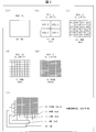
- FIG. 2 is a diagram showing an example in which an input image is divided hierarchically.
- 2A shows an example of division of the 0th layer
- FIG. 2B shows an example of division of the first layer
- FIG. 2C shows division of the second layer.
- An example is shown
- (d) of FIG. 2 shows an example of the division of the third hierarchy
- (e) of FIG. 2 shows an example of the division of the fourth hierarchy.
- FIG. 2F shows the hierarchical structure of the 0th to 4th hierarchies.
- the input image is divided as follows in each layer.
- Layer 0 (L0): Not divided (the number of divided areas is 1).
- First layer (L1) Divided into two vertically and horizontally (the number of divided areas is 4).
- Second layer (L2) Divided into 4 parts vertically and horizontally (the number of divided areas is 16).
- Third layer (L3) Divided into 8 parts vertically and horizontally (the number of divided areas is 64).
- the number of layers may be 2 or more, 4 or less, or 6 or more. Further, the number of divided areas in each layer may be set as appropriate.
- the score calculation unit 12 calculates a score indicating the degree of specific texture (for example, glossiness) in each of the plurality of divided regions.
- a learned model having a neural network can be used as the score calculation unit 12.
- the score calculation unit 12 includes a learned model learned by using a plurality of images of an object having a specific texture.
- the neural network is provided between an input layer that is an uppermost layer to which input data is input, an output layer that is a lowermost layer that outputs output data (the score), and the input layer and the output layer.
- a three-layer neural network including an intermediate layer.
- the number of intermediate layers is, for example, 20 to 25 layers, but is not limited to this example.
- the neural network is made to read a large number of images (referred to as a learning data set) with glossy or non-glossy tags and learn glossiness. Let (supervised learning). The number of images included in the learning data set is about 20,000 to 30,000, and each image includes images of various types of objects.
- the node value is transmitted from the upper layer to the lower layer, and weighting is performed using the weight parameter set for each connection between the nodes.
- the error back propagation method is a method of adjusting (learning) each weight parameter so that the difference between the output y when the input x is input and the true output y (teacher) is reduced for each neuron. .
- each weight parameter is optimized, and a neural network capable of generating a score indicating the degree of glossiness is constructed.
- a learning data set including an image with a tag with or without the texture is read into the neural network and learned. That's fine.
- a learned model obtained by performing machine learning other than deep learning may be used as the score calculation unit 12.
- FIG. 3 is a diagram illustrating an example of processing in the score calculation unit 12.
- the score calculation unit 12 calculates a score for each of a total of 341 divided regions in the 0th to 4th layers generated by dividing the input image.
- a recognition process 12a for calculating the score, and (ii) a position specifying process 12b for acquiring position information ([x, y] [0, 1]) of the divided area.
- the position information of the divided areas is generated by the dividing unit 11 along with the process of dividing the input image and is stored in the storage unit 30.
- the score calculation unit 12 performs the same processing for each divided region of the input image, and creates data in which the score and the position information are linked.
- the score in the present embodiment is the probability that the divided area has glossiness, and is calculated in the range of 0% or more and 100% or less.
- the score calculation unit 12 further adds the scores of the divided areas having a correspondence relationship between the plurality of divided images (between hierarchies), so that each division in the divided image (fourth hierarchy) having the largest number of divided areas is performed.
- the area score is calculated.
- the set of scores is referred to as a score mask. The score mask will be specifically described below.
- the score of each divided area is represented as Sn [x, y].
- n is a hierarchy (0 to 4).
- the image is divided into 4 n divided regions, and the score is calculated for each divided region. Therefore, the number of scores in the layer is 4 n .
- x and y indicate the positions of the divided areas.
- the scores at the four corners of the fourth layer are S4 [0,0], S4 [15,0], S4 [0,15], and S4 [15,15], respectively.
- the score included in the score mask is obtained by normalizing the scores in the divided areas of each hierarchy by adding the scores between the hierarchies. For this reason, the number of scores included in the score mask is the same as that of the hierarchy having the largest number of scores. In the example illustrated in FIG. 2, the fourth hierarchy having 256 scores is the hierarchy having the largest number of divided areas. For this reason, the score mask also has 256 scores.
- SM [0,0] S0 [0,0] + S1 [0,0] + S2 [0,0] + S3 [0,0] + S4 [0,0]
- SM [15,0] S0 [0,0] + S1 [1,0] + S2 [3,0] + S3 [7,0] + S4 [15,0]
- SM [0,15] S0 [0,0] + S1 [0,1] + S2 [0,3] + S3 [0,7] + S4 [0,15]
- SM [15,15] S0 [0,0] + S1 [1,1] + S2 [3,3] + S3 [7,7] + S4 [15,15]
- SM [15,15] S0 [0,0] + S1 [1,1] + S2 [3,3] + S3 [7,7] + S4 [15,15]
- SM [x, y] is expressed by the following equation.
- the score of each divided area is a probability that the divided area is glossy, and takes a value of 0% or more and 100% or less. For this reason, the sum of the scores of the divided areas of the 0th to 4th hierarchies takes a value of 0% to 500%. In the above formula, in order to normalize the score, the sum of the scores of the divided areas of each layer is divided by 5 which is the number of layers.
- the scores in each layer are linearly added. Therefore, for example, even if the score in the lower divided region (large divided region) is low, the glossiness in the divided region becomes stronger if the score in the upper divided region (small divided region) is high.
- the score calculation unit 12 can flexibly cope with the position and size of the object in the image by calculating the scores for the divided areas with different sizes divided by the dividing unit 11. That is, the score calculation unit 12 can calculate a score according to the presence or absence of glossiness regardless of the size of the object in the image. In general, when the proportion of the object in the divided region is high, the recognition processing by the score calculation unit 12 tends to be performed correctly as compared with the case where the proportion is low.
- the score correction unit 13 extracts information related to a specific texture level from the input image, and corrects the score calculated by the score calculation unit 12 based on the extracted information.
- the score correction unit 13 since the specific texture is glossiness, the score correction unit 13 extracts luminance information as information related to the degree of glossiness, and luminance information corresponding to each of the plurality of divided regions. Is used to correct the score of the divided area.
- the score correction unit 13 performs the following processing.
- the score correction unit 13 extracts the luminance information (Y) after converting the input image into the YUV format.
- the score correction unit 13 converts the input image into a luminance image indicating luminance information.
- the score correction unit 13 calculates a correction value that is a value obtained by normalizing the luminance of the divided region for each of the divided regions similar to the score mask in the luminance image.
- the luminance of each divided region can be obtained as an average value of luminance values indicated by a plurality of pixels included in the divided region, for example.
- a set of combinations of the calculated correction value and information for specifying a divided area of the score mask to which each correction value is applied is referred to as a correction mask.
- the score calculated by the score calculation unit 12 may include a score calculated based on misrecognition. For this reason, in the score mask, there is a possibility that a divided area which does not actually have a glossy feeling has a high score. Therefore, the score correction unit 13 generates a correction mask and corrects the score mask.
- the score mask reliability can be improved by correcting the score mask using the luminance for each divided region of the input image.
- the score correction unit 13 may correct (blur processing) the score of each divided region so that the difference between the scores of the adjacent divided regions becomes small.
- a correction method for example, there is a method of correcting the luminance of each divided region so that the difference in luminance between adjacent divided regions in the luminance image becomes small. This example will be described below.
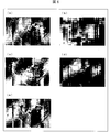
- FIG. 4A shows an example of an input image.
- FIG. 4B is a diagram showing a luminance image generated by extracting luminance information from the input image shown in FIG.
- the luminance image is generated by extracting luminance information (Y) from a YUV format image.
- FIG. 4 is a diagram showing a luminance image after performing the blurring process on the luminance image shown in (b) of FIG.
- the edges of the input image shown in FIG. 4A and the luminance image shown in FIG. 4B are clear.
- a luminance image with blurred edges is obtained as shown in FIG. 4C.
- the score correction unit 13 does not necessarily need to execute the blurring process. However, since the edge portion of the image is blurred when the blurring process is executed, a rapid change in the correction value in the divided region corresponding to the edge portion and the score corrected by the correction value is suppressed. As a result, the image quality failure at the edge portion is suppressed. Therefore, it is preferable that the score correction unit 13 performs a blurring process on the luminance image.
- the texture adjustment unit 14 adjusts a specific texture according to the score calculated by the score calculation unit 12 and corrected by the score correction unit 13 for a plurality of divided regions.
- the texture adjusting unit 14 emphasizes a specific texture for a divided area having a score equal to or higher than a predetermined value among the plurality of divided areas.
- the predetermined value may be appropriately set according to the type of texture to be emphasized.
- the specific texture is gloss.
- the texture adjustment unit 14 performs luminance adjustment, contrast adjustment, edge enhancement processing, or a combination thereof in each divided region of the input image for a divided region having a score equal to or greater than a predetermined value.
- a multi-step may be set so that it may select, as mentioned later.
- the texture adjusting unit 14 can enhance the glossiness of the divided region by executing processing including contrast enhancement and edge enhancement for the divided region having a score equal to or greater than a predetermined value.
- the change in the output luminance gradation with respect to the input image luminance gradation can be made steep.
- the shadow of the object in the output image appears to be relatively dark, so that the stereoscopic effect can be enhanced.
- FIG. 5 is a flowchart showing a flow of processing (image processing method) executed by the image processing unit 10.
- FIG. 6A is a diagram illustrating an example of an input image.
- FIG. 6B is a diagram illustrating a score mask corresponding to the input image.
- (C) of FIG. 6 is a figure which shows the brightness
- FIG. 6D shows only the divided areas where the glossiness is emphasized.
- FIG. 6E is a diagram illustrating an output image whose texture has been adjusted.
- the dividing unit 11 divides an input image as shown in FIG. 6A in a plurality of divided patterns having a plurality of divided regions, and thereby has a plurality of divided regions. (S1, division process).
- the score calculation unit 12 calculates a score for each divided region (S2, score calculation step), and generates a score mask by adding the scores of the divided regions that are in a correspondence relationship between layers (S3).
- FIG. 6B shows an image of the score mask visualized so that the divided region having a higher score becomes closer to white.
- the score correction unit 13 In parallel with steps S1 to S3, the score correction unit 13 generates a correction mask including a correction value based on the luminance value indicated by the luminance image as shown in FIG. 6C (S4). Further, the score correction unit 13 corrects the score mask using the correction mask (S5).
- the texture adjusting unit 14 executes a process of enhancing the texture (glossiness) for the divided areas whose score is a predetermined value or more in the score mask (S6, texture adjusting process). Specifically, as shown in FIG. 6D, the texture adjusting unit 14 generates an enhanced image in which glossiness is enhanced only in the divided areas having a score equal to or higher than a predetermined value. Furthermore, the texture adjusting unit 14 generates an output image shown in FIG. 6E by synthesizing the input image and the emphasized image.
- step S2 to S4 may be executed in this order, and step S4 may be executed before steps S2 and S3.
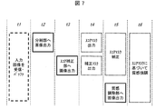
- FIG. 7 is a diagram illustrating processing timing in the image processing unit 10.
- t1 to t6 are times when some processing is executed in the image processing unit 10.
- the receiving unit 20 receives an input image and stores it in a buffer.
- the receiving unit 20 outputs the buffered input image to the dividing unit 11 at time t2.
- the dividing unit 11 divides the image into a plurality of divided areas.
- the score calculation unit 12 calculates a score for each of the divided regions and generates a score mask.
- the receiving unit 20 outputs the input image to the score correction unit 13 at time t3 after time t2. This is because the time required for the processing in the division unit 11 and the score calculation unit 12 is longer than the time required for the processing in the score correction unit 13. Thus, by providing a time difference between time t2 and time t3, both the score mask and the correction mask are generated at time t4.
- the score correction unit 13 corrects the score mask using the correction mask.
- the receiving unit 20 outputs the input image to the texture adjusting unit 14 at the same timing as the correction. Thereby, at time t6, the texture adjusting unit 14 can adjust the glossiness of the input image using the corrected score mask.
- FIG. 8 is a diagram for explaining an example of processing by the image processing apparatus 100.
- 8A is a conceptual diagram of an image (input image) input to the image processing apparatus 100
- FIG. 8B is a conceptual diagram of a score mask generated by the score calculation unit 12
- FIG. c) is a conceptual diagram showing an image (output image) output from the image processing apparatus 100.
- FIG. 8A is a conceptual diagram of an image (input image) input to the image processing apparatus 100
- FIG. 8B is a conceptual diagram of a score mask generated by the score calculation unit 12
- FIG. c) is a conceptual diagram showing an image (output image) output from the image processing apparatus 100.
- the score mask will be described as a set of scores for each of the divided areas obtained by dividing the input image into eight parts in the vertical and horizontal directions.
- 1 is set when there is glossiness, and 0 when there is no glossiness.
- the input image shown in FIG. 8A includes images of a metal spoon and a ceramic spoon.
- the image of the metal spoon is glossy.
- the image of a ceramic spoon has no gloss.
- the score calculation unit 12 sets the score of the divided area corresponding to the image of the metal spoon to 1, and sets the score of the other divided areas to 0. Generate a mask.
- the texture adjusting unit 14 executes a process of emphasizing glossiness in a divided area where the score in each divided area of the texture mask shown in FIG. 8B is 0.5 or more, and the score is less than 0.5. Processing for enhancing glossiness is not performed on the divided areas. Thereby, as shown in FIG. 8C, the glossiness is emphasized only in the divided areas corresponding to the image of the metal spoon, and the divided areas corresponding to the other divided areas, for example, the image of the ceramic spoon. In the area, an image that is not emphasized is output to the display device 200.
- the score may take a decimal value between 0 and 1, for example.
- the score calculation unit 12 takes a value of 0.5 or more and 1 or less in the divided area having glossiness, and the score in the divided area not having the glossiness is 0 or more and less than 0.5. A score mask like this is generated.
- the score may take a value in a range different from 0 or more and 1 or less, for example.
- the texture adjusting unit 14 may execute a process of enhancing glossiness for a divided region having a score equal to or higher than the predetermined value with a predetermined value different from 0.5 as a reference.
- the texture adjusting unit 14 may set a plurality of stages of processing for enhancing the glossiness, and may determine which stage of processing is performed on the divided area according to the score of the divided area. In this case, parameters used for the brightness adjustment process, contrast adjustment process, or edge enhancement process are associated in advance for each stage.
- the parameter in the brightness adjustment process is a ⁇ value.
- p is a pixel value in the output image of the pixel to be processed
- p0 is a pixel value in the input image of the pixel.
- ⁇ (1 / ⁇ ) means 1 / ⁇ power. As ⁇ increases from 1, the luminance after the luminance adjustment processing becomes larger than the luminance before the processing.
- the parameter in the contrast adjustment process is a coefficient ⁇ that is multiplied by the difference between the pixel value of the pixel to be processed and the intermediate value.
- pth is an intermediate value of pixel values (that is, a reference value for increasing or decreasing the pixel value by contrast adjustment processing). As ⁇ increases, pixel values larger than the intermediate value become larger, and pixel values smaller than the intermediate value become smaller.
- the parameter in the edge enhancement process is a ratio ⁇ 2 / ⁇ 1 of a coefficient ⁇ 2 that multiplies a pixel value around the pixel to be processed with respect to a coefficient ⁇ 1 that multiplies the pixel value of the pixel to be processed for the edge enhancement process.
- p1 to p4 are pixel values of pixels adjacent to the four sides of the pixel to be processed. As ⁇ 2 / ⁇ 1 increases, more edges are emphasized.
- the glossiness enhancement stage is set in, for example, three stages of “none”, “medium”, and “strong”.
- the above parameters are set (through setting) so that the amount of change in the pixel value before and after the process is zero.
- the value of ⁇ is set to 1, and ⁇ and ⁇ 2 / ⁇ 1 are set to 0.
- the above parameters are set to values that emphasize glossiness. Specifically, for example, the value of ⁇ is set to a value greater than 1, and ⁇ and ⁇ 2 / ⁇ 1 are set to a value greater than 0.
- the emphasis stage is “strong”, the amount of change in the parameter is set to a value that further enhances the glossiness (that is, the maximum value in the image processing apparatus 100) than when the emphasis stage is “medium”.
- the gloss enhancement step may be set in four or more steps. For example, when there are a large number of stages, such as 256 stages, a table showing the values of the parameters corresponding to the respective stages may be referred to, and the parameters may be interpolated arithmetically (for example, linearly).
- the texture adjusting unit 14 does not limit the divided areas whose glossiness is to be adjusted based on the score, but may set all the divided areas as the target. After that, the texture adjustment unit 14 adjusts the texture of each divided region of the input image by increasing or decreasing the parameter of the texture to be changed for the texture adjustment according to the score calculated by the score calculation unit 12. May be.
- the texture adjusting unit 14 employs a value obtained by multiplying the maximum change amount, which is the difference between the minimum value and the maximum value that can be taken by the parameter, by the score as a weighting factor, as the value of the parameter.
- the value of the parameter used for texture adjustment is obtained by multiplying the maximum value by the score.
- the brightness adjustment process, the contrast adjustment process, and the edge enhancement process are not limited to the above example, and the above parameters vary depending on the content of the process.
- the image processing apparatus 100 does not necessarily include the score correction unit 13.
- the texture adjustment unit 14 adjusts a specific texture according to the score calculated by the score calculation unit 12.
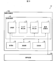
- FIG. 9 is a block diagram showing a configuration of an image display system 1A including the image processing apparatus 100A according to the present embodiment.
- the image display system 1A is different from the image display system 1 in that it includes the image processing apparatus 100A instead of the image processing apparatus 100.
- the image processing apparatus 100A includes a communication unit 40 in addition to the components included in the image processing apparatus 100.
- the communication unit 40 communicates with an external device in order to update the learned model included in the score calculation unit 12.
- the image processing apparatus 100A can improve the accuracy of the recognition process in which the score calculation unit 12 calculates the score.
- the image processing apparatus 100A illustrated in FIG. 9 includes the receiving unit 20 and the communication unit 40 separately.
- the receiving unit 20 and the communication unit 40 may be a common member.
- FIG. 10 is a diagram showing a configuration of a general information terminal 2.
- the information terminal 2 may be, for example, a workstation, a personal computer, a smartphone, or a tablet.
- the information terminal 2 includes a control CPU (Central Processing Unit) 201, an image processing GPU (Graphics Processing Unit) 202 capable of parallel arithmetic processing, a RAM (Random Access Memory) 203, a storage unit 204, a display 205, A camera 206 that captures images and videos, a communication unit 207 that performs wireless communication, an audio input / output 208, a sensor 209 such as a touch panel or buttons, and a connector 210 are connected to each other via a bus 211.
- a control CPU Central Processing Unit
- GPU Graphics Processing Unit
- RAM Random Access Memory
- a camera 206 that captures images and videos
- a communication unit 207 that performs wireless communication
- an audio input / output 208 a sensor 209 such as a touch panel or buttons
- Such an information terminal 2 can function as an information processing apparatus according to an aspect of the present disclosure.
- the input image stored in the storage unit 204 is divided into a plurality of divided regions by the process of step S1 shown in FIG.
- the GPU 202 executes the processes of steps S2 and S3 and the process of step S4 in parallel, and further executes the process of step S5.
- the CPU 201 executes the process of step S6.
- the processed output image is displayed on the display 205.
- the output image may be stored in the storage unit 204 or may be output to the outside via the communication unit 207 or the connector 210.
- the image processing apparatus 100 increases or decreases the texture parameter to be changed for texture adjustment according to the score calculated by the score calculation unit 12.
- the texture of each divided area of the input image is adjusted.
- the image processing apparatus 100 according to the present embodiment is configured such that the user can adjust the manner or degree in which the score correction unit 13 corrects the score. For example, a plurality of stages are set for the degree to which the score correction unit 13 corrects the score, and the user may select a desired stage among the plurality of stages.
- the above selection may be performed using, for example, a menu displayed on the display unit provided in the image processing apparatus.
- the above-described selection dial or lever may be provided in the image processing apparatus.
- Magnification for multiplying the score is defined for each of the above-mentioned plurality of stages.
- the score correction unit 13 multiplies the score value in each divided region by a magnification according to the stage selected by the user. By multiplying the above magnification, the degree of glossiness adjustment according to the score is increased or decreased.
- a stage where the score value becomes negative may be set.
- the score value is negative, as the score value approaches ⁇ 1, the adjustment amount for reducing the glossiness increases. For this reason, the glossiness of the divided area having the glossiness is reduced.
- the user can adjust the manner and degree in which the texture adjustment unit 14 adjusts the texture by adjusting the manner or degree in which the score correction unit 13 corrects the score. it can.
- control blocks (particularly, the dividing unit 11, the score calculating unit 12, the score correcting unit 13, and the texture adjusting unit 14) of the image processing apparatuses 100 and 100A are formed by a logic circuit (hardware) formed in an integrated circuit (IC chip) or the like. It may be realized or may be realized by software using a CPU (Central Processing Unit).
- a logic circuit hardware
- IC chip integrated circuit
- CPU Central Processing Unit
- the image processing apparatuses 100 and 100A have a CPU that executes instructions of an image processing program, which is software that realizes each function, and the image processing program and various data recorded in a computer (or CPU) so that they can be read.
- a ROM (Read Only Memory) or a storage device (these are called “recording media”), a RAM (Random Access Memory) for developing the image processing program, and the like are provided.
- the computer (or CPU) reads the image processing program from the recording medium and executes it, thereby achieving the object of one aspect of the present disclosure.
- a “non-temporary tangible medium” such as a tape, a disk, a card, a semiconductor memory, a programmable logic circuit, or the like can be used.
- the image processing program may be supplied to the computer via any transmission medium (communication network, broadcast wave, etc.) capable of transmitting the image processing program.
- any transmission medium communication network, broadcast wave, etc.
- one aspect of the present disclosure can also be realized in the form of a data signal embedded in a carrier wave, in which the image processing program is embodied by electronic transmission.
- An image processing apparatus is an image processing apparatus that adjusts the texture of an image, and includes a dividing unit that divides the image into a plurality of divided areas, and a specific texture in each of the plurality of divided areas.
- a score calculation unit that calculates a score indicating the degree of the texture, and a texture adjustment unit that adjusts the specific texture according to the scores of the plurality of divided regions.
- the dividing unit divides the input image into a plurality of divided regions, and the score calculating unit calculates a score indicating the degree of specific texture in each of the plurality of divided regions.
- the texture adjusting unit executes a process of adjusting the specific texture according to the score of the divided area. Therefore, it is possible to recognize a specific texture for each divided region and adjust the specific texture.
- the texture adjustment unit emphasizes the specific texture for a divided area in which the score is a predetermined value or more among the plurality of divided areas. It is preferable.
- the specific texture can be emphasized only for the divided areas having a score equal to or higher than a predetermined value.
- the dividing unit divides the image in a plurality of pattern division modes having different numbers of the divided regions
- the score calculating unit includes: It is possible to calculate the score of each divided region in the divided image having the largest number of divided regions by adding the scores of the divided regions corresponding to each other between the plurality of divided images divided in the above-described division pattern of the plurality of patterns. preferable.
- the score of a plurality of divided images divided in a plurality of pattern division modes having different numbers of divided regions can be used for final score calculation. Therefore, an appropriate score can be calculated flexibly corresponding to various sizes and positions of objects in the image.
- the image processing apparatus in any one of Aspects 1 to 3, extracts information related to the specific texture level from the image, and based on the extracted information, the score It is preferable to further include a score correction unit that corrects the score calculated by the calculation unit.
- the score correction unit can correct the score to an appropriate value.
- the specific texture is glossiness
- the score correction unit extracts luminance information as the relevant information, and It is preferable to correct the score of the divided area using luminance information corresponding to each of the divided areas.
- the score correction unit can correct the score of the divided area using the luminance information of the divided area.
- the score correction unit may correct the score of each divided region so that the difference between the scores of the adjacent divided regions is small. Good.
- the score calculation unit includes a learned model learned using a plurality of images of the object having the specific texture. It is preferable.
- the presence / absence of a specific texture in the divided region can be appropriately determined by the learned model.
- the image processing apparatus preferably further includes a communication unit that communicates with an external apparatus in order to update the learned model.
- the user may be able to adjust the manner or degree in which the score correction unit corrects the score.
- the manner or degree by which the score correction unit corrects the score can be adjusted according to the subjectivity of the user.
- the texture adjusting unit performs brightness adjustment, contrast adjustment, or edge enhancement processing of the image.
- the glossiness of the image can be adjusted by brightness adjustment, contrast adjustment, or edge enhancement processing.
- the image processing method is an image processing method for adjusting the texture of an image, and includes a dividing step of dividing the image into a plurality of divided regions, and a specific texture in each of the plurality of divided regions.
- the image processing apparatus may be realized by a computer.
- the image processing apparatus is operated on each computer by causing the computer to operate as each unit (software element) included in the image processing apparatus.
- An image processing program of an image processing apparatus to be realized in this manner and a computer-readable recording medium that records the image processing program also fall within the category of one aspect of the present disclosure.
Landscapes
- Engineering & Computer Science (AREA)
- Physics & Mathematics (AREA)
- General Physics & Mathematics (AREA)
- Theoretical Computer Science (AREA)
- Computer Vision & Pattern Recognition (AREA)
- Image Processing (AREA)
Abstract
画像に含まれる像の質感を適切に表現することが可能な画像処理装置などを実現する。画像処理装置(100)は、画像を複数の分割領域に分割する分割部(11)と、複数の分割領域のそれぞれにおける特定の質感の程度を示すスコアを算出するスコア算出部(12)と、複数の分割領域のスコアに応じて特定の質感を調整する質感調整部(14)とを備える。
Description
以下の開示は、画像の質感を調整する画像処理装置などに関する。
特許文献1には、画素ごとの光沢付加量に基づいて階調処理の方式を切り換える画像形成装置が開示されている。
特許文献1に開示されている画像形成装置では、画素ごとに光沢付加量を判定しているため、画像に含まれている物体の像に対して光沢付加量を適切に決定できない虞がある。
本開示の一態様は、画像に含まれる像の質感を適切に表現することが可能な画像処理装置などを実現することを目的とする。
上記の課題を解決するために、本開示の一態様に係る画像処理装置は、画像の質感を調整する画像処理装置であって、上記画像を複数の分割領域に分割する分割部と、上記複数の分割領域のそれぞれにおける特定の質感の程度を示すスコアを算出するスコア算出部と、上記複数の分割領域の上記スコアに応じて上記特定の質感を調整する質感調整部とを備える。
また、本開示の一態様に係る画像処理方法は、画像の質感を調整する画像処理方法であって、上記画像を複数の分割領域に分割する分割工程と、上記複数の分割領域のそれぞれにおける特定の質感の程度を示すスコアを算出するスコア算出工程と、上記複数の分割領域の上記スコアに応じて上記特定の質感を調整する質感調整工程とを含む。
本開示の一態様によれば、画像に含まれる像の質感を適切に表現できる。
〔実施形態1〕
以下、本開示の実施の形態について詳細に説明する。図1は、本実施形態の画像処理装置100を含む画像表示システム1の構成を示すブロック図である。画像表示システム1は、画像処理装置100および表示装置200を含む。画像処理装置100は、画像処理装置100に入力された画像(入力画像)の特定の質感を調整する処理を実行する装置である。以下の説明では、画像処理装置100は、前記特定の質感として、光沢感を調整するものとする。画像処理装置100の調整の対象となる質感は、光沢感に限定されず、例えば、材質感(例えば、ざらつき)、立体感などであってもよい。また、入力画像は、動画であっても静止画であってもよい。
以下、本開示の実施の形態について詳細に説明する。図1は、本実施形態の画像処理装置100を含む画像表示システム1の構成を示すブロック図である。画像表示システム1は、画像処理装置100および表示装置200を含む。画像処理装置100は、画像処理装置100に入力された画像(入力画像)の特定の質感を調整する処理を実行する装置である。以下の説明では、画像処理装置100は、前記特定の質感として、光沢感を調整するものとする。画像処理装置100の調整の対象となる質感は、光沢感に限定されず、例えば、材質感(例えば、ざらつき)、立体感などであってもよい。また、入力画像は、動画であっても静止画であってもよい。
図1に示すように、画像処理装置100は、画像処理部10、受信部20、および記憶部30を備える。表示装置200は、画像処理装置100により処理された画像を表示する装置である。
画像処理部10は、分割部11、スコア算出部12、スコア補正部13および質感調整部14を備える。画像処理部10が備える各部については後述する。受信部20は、放送により送信される画像を入力画像として受信する。また、受信部20は、受信した入力画像を、適切なタイミングで分割部11、スコア補正部13および質感調整部14に出力するバッファ処理を実行する。なお、受信部20は、入力画像のデータが記憶された記憶媒体から当該データを読み取ってもよい。記憶部30は、画像処理部10による処理に必要な情報を記憶する。
(分割部11)
分割部11は、入力画像を複数の分割領域に分割する。本実施形態では、分割部11は、分割領域の数が互いに異なる複数パターンの分割様式で上記画像を分割する。以下の説明では、互いに異なる複数パターンの分割様式のそれぞれを階層と称する。
分割部11は、入力画像を複数の分割領域に分割する。本実施形態では、分割部11は、分割領域の数が互いに異なる複数パターンの分割様式で上記画像を分割する。以下の説明では、互いに異なる複数パターンの分割様式のそれぞれを階層と称する。
図2は、入力画像を階層的に分割した例を示す図である。図2の(a)は、第0階層の分割の例を示し、図2の(b)は、第1階層の分割の例を示し、図2の(c)は、第2階層の分割の例を示し、図2の(d)は、第3階層の分割の例を示し、図2の(e)は、第4階層の分割の例を示す。また、図2の(f)は、第0~第4階層の階層構造を示す図である。
図2の(a)~(f)に示す例では、各階層において入力画像は以下のとおり分割される。
・第0階層(L0):分割されない(分割領域数は1)。
・第1階層(L1):縦および横のそれぞれに2分割される(分割領域数は4)。
・第2階層(L2):縦および横のそれぞれに4分割される(分割領域数は16)。
・第3階層(L3):縦および横のそれぞれに8分割される(分割領域数は64)。
・第4階層(L4):縦および横のそれぞれに16分割される(分割領域数は256)。なお、本開示の一態様において、階層の数は2以上4以下または6以上であってもよい。また、それぞれの階層における分割領域の数も、適宜設定されてよい。
・第0階層(L0):分割されない(分割領域数は1)。
・第1階層(L1):縦および横のそれぞれに2分割される(分割領域数は4)。
・第2階層(L2):縦および横のそれぞれに4分割される(分割領域数は16)。
・第3階層(L3):縦および横のそれぞれに8分割される(分割領域数は64)。
・第4階層(L4):縦および横のそれぞれに16分割される(分割領域数は256)。なお、本開示の一態様において、階層の数は2以上4以下または6以上であってもよい。また、それぞれの階層における分割領域の数も、適宜設定されてよい。
このように、複数の階層において画像を分割することで、画像に含まれる物体の位置および大きさに、柔軟に対応することができる。
(スコア算出部12)
スコア算出部12は、複数の分割領域のそれぞれにおける特定の質感(例えば、光沢感)の程度を示すスコアを算出する。スコア算出部12として、ニューラルネットワークを有する学習済みモデルを用いることができる。換言すれば、スコア算出部12は、特定の質感を有する物体の画像を複数用いて学習した学習済みモデルを含んでいる。
スコア算出部12は、複数の分割領域のそれぞれにおける特定の質感(例えば、光沢感)の程度を示すスコアを算出する。スコア算出部12として、ニューラルネットワークを有する学習済みモデルを用いることができる。換言すれば、スコア算出部12は、特定の質感を有する物体の画像を複数用いて学習した学習済みモデルを含んでいる。
上記ニューラルネットワークは、入力データが入力される最上位層である入力層と、出力データ(上記スコア)を出力する最下位層である出力層と、入力層と出力層との間に設けられた中間層とを含む、三層のニューラルネットワークである。中間層の数は、例えば、20~25層であるが、この例に限定されない。
スコア算出部12が光沢感を判定するものである場合、上記ニューラルネットワークに対して、光沢有りまたは光沢無しのタグを付与した多数の画像(学習データセットと称する)を読み込ませ、光沢感を学習させる(教師あり学習)。学習データセットに含まれる画像の数は、2万~3万枚程度であり、各画像には、様々な種類の物体の像が含まれている。
ニューラルネットワークでは、上位階層から下位階層にノード値が伝達されるが、この伝達の際に、ノード間の接続毎に設定された重みパラメータを用いた重み付けが行われる。これらの重みは、誤差逆伝搬法(バックプロパゲーション)により学習可能なものである。誤差逆伝搬法は、各ニューロンについて、入力xが入力されたときの出力yと真の出力y(教師)との差分を小さくするように、それぞれの重みパラメータを調整(学習)する手法である。学習データセットを用いた学習により、各重みパラメータが最適化され、光沢感の程度を示すスコアを生成可能なニューラルネットワークが構築される。
このような学習方法(ディープラーニング)によって構築した学習済みモデルに対して、タグの付与されていない画像における光沢感の有無を判定させたところ、約90%の正解率が得られた。
光沢感以外の質感(例えば、立体感)をニューラルネットワークに判定させる場合には、当該質感有りまたは当該質感無しのタグを付与した画像を含む学習データセットを当該ニューラルネットワークに読み込ませ、学習させればよい。
また、スコア算出部12として、ディープラーニング以外の機械学習を行った学習済みモデルを利用してもよい。
図3は、スコア算出部12における処理の例を示す図である。本実施形態のスコア算出部12は、入力画像を分割することによって生成された第0~第4階層の、合計341の分割領域のそれぞれについてスコアを算出する。図3に示す例は、スコア算出部12が、入力画像の第1階層における[x、y]=[0,1]の分割領域(4分割された入力画像の左下の領域)について、(i)上記スコアを算出する認識処理12a、および(ii)当該分割領域の位置情報([x、y]=[0,1])を取得する位置特定処理12b、を実行することを示している。分割領域の位置情報は、入力画像を分割する処理に伴って分割部11によって生成され、記憶部30に格納されている。
スコア算出部12は、入力画像の各分割領域について同様の処理を行い、スコアと位置情報とを紐づけしたデータを作成する。本実施形態におけるスコアは、分割領域が光沢感を有する確率であり、0%以上かつ100%以下の範囲で算出される。
また、スコア算出部12はさらに、複数の分割画像間(階層間)で対応関係にある分割領域のスコアを加算することにより、最も分割領域の数が多い分割画像(第4階層)における各分割領域のスコアを算出する。上記スコアの集合をスコアマスクと称する。スコアマスクについて以下に具体的に説明する。
それぞれの分割領域のスコアをSn[x,y]と表す。nは階層(0~4)である。第n階層において、画像は4nの分割領域に分割され、分割領域ごとにスコアが算出されるため、当該階層におけるスコアの数も4nである。xおよびyは、分割領域の位置を示す。[x,y]=[0,0]が画像の左上隅の分割領域の位置を示し、[x,y]=[2n-1,2n-1]が画像の右下隅の分割領域の位置を示す。例えば第4層の4隅のスコアは、それぞれS4[0,0]、S4[15,0]、S4[0,15]、およびS4[15,15]となる。
スコアマスクに含まれるスコアは、各階層の分割領域におけるスコアを階層間で加算し、正規化したものである。このため、スコアマスクに含まれるスコアの個数は、最もスコアの個数が多い階層のものと同じになる。図2に示す例では、スコアが256個である第4階層が最も分割領域数が多い階層である。このため、スコアマスクも256個のスコアを有する。
16×16分割のスコアマスクにおけるスコアの値をSM[x,y]とすると、例えば当該スコアマスクの4隅のスコアは、それぞれ以下のように表される。
SM[0,0]=S0[0,0]+S1[0,0]+S2[0,0]+S3[0,0]+S4[0,0]
SM[15,0]=S0[0,0]+S1[1,0]+S2[3,0]+S3[7,0]+S4[15,0]
SM[0,15]=S0[0,0]+S1[0,1]+S2[0,3]+S3[0,7]+S4[0,15]
SM[15,15]=S0[0,0]+S1[1,1]+S2[3,3]+S3[7,7]+S4[15,15]
これを一般化すると、SM[x,y]は以下の式で表される。
SM[x,y]=(S0[0,0]+S1[int(x/8),int(y/8)]+S2[int(x/4),int(y/4)]+S3[int(x/2),int(y/2)]+S4[x,y])/5
ここで、int()は小数部分の切り捨てによる整数化を意味する。
SM[0,0]=S0[0,0]+S1[0,0]+S2[0,0]+S3[0,0]+S4[0,0]
SM[15,0]=S0[0,0]+S1[1,0]+S2[3,0]+S3[7,0]+S4[15,0]
SM[0,15]=S0[0,0]+S1[0,1]+S2[0,3]+S3[0,7]+S4[0,15]
SM[15,15]=S0[0,0]+S1[1,1]+S2[3,3]+S3[7,7]+S4[15,15]
これを一般化すると、SM[x,y]は以下の式で表される。
SM[x,y]=(S0[0,0]+S1[int(x/8),int(y/8)]+S2[int(x/4),int(y/4)]+S3[int(x/2),int(y/2)]+S4[x,y])/5
ここで、int()は小数部分の切り捨てによる整数化を意味する。
上述したとおり、本実施形態では、個々の分割領域のスコアは当該分割領域が光沢を有する確率であり、0%以上かつ100%以下の値を取る。このため、第0~第4階層の各階層の分割領域のスコアの和は、0%以上かつ500%以下の値を取る。上記の式においては、スコアを正規化するため、各階層の分割領域のスコアの和を階層の数である5で除している。
SM[x,y]の算出においては、各階層におけるスコアが線形に加算される。したがって、例えば下位の階層の分割領域(大きな分割領域)におけるスコアが低い場合でも、上位の階層の分割領域(小さな分割領域)におけるスコアが高ければ、その分割領域における光沢感は強くなる。
スコア算出部12は、分割部11が分割した、互いにサイズの異なる分割領域についてスコアを算出することで、画像における物体の位置および大きさなどに柔軟に対応することができる。すなわち、スコア算出部12は、画像における物体の大小によらず、光沢感の有無に応じたスコアを算出することができる。一般に、分割領域内における物体の占める割合が高い場合には、当該割合が低い場合と比較して、スコア算出部12による認識処理が正しく行われる傾向がある。
(スコア補正部13)
スコア補正部13は、特定の質感の程度と関連性のある情報を入力画像から抽出し、抽出した情報に基づいて、スコア算出部12が算出したスコアを補正する。本実施形態では、上記特定の質感は光沢感であるため、スコア補正部13は、光沢感の程度と関連性のある情報として輝度情報を抽出し、複数の分割領域のそれぞれに対応する輝度情報を用いて当該分割領域のスコアを補正する。
スコア補正部13は、特定の質感の程度と関連性のある情報を入力画像から抽出し、抽出した情報に基づいて、スコア算出部12が算出したスコアを補正する。本実施形態では、上記特定の質感は光沢感であるため、スコア補正部13は、光沢感の程度と関連性のある情報として輝度情報を抽出し、複数の分割領域のそれぞれに対応する輝度情報を用いて当該分割領域のスコアを補正する。
具体的には、スコア補正部13は、以下の処理を実行する。
・入力画像がRGB形式で表現されている場合、スコア補正部13は、当該入力画像をYUV形式に変換した上で、輝度情報(Y)を抽出する。換言すれば、スコア補正部13は、入力画像を、輝度情報を示す輝度画像に変換する。
・スコア補正部13は、輝度画像における、スコアマスクと同様の分割領域のそれぞれについて、当該分割領域の輝度を正規化した値である補正値を算出する。
・入力画像がRGB形式で表現されている場合、スコア補正部13は、当該入力画像をYUV形式に変換した上で、輝度情報(Y)を抽出する。換言すれば、スコア補正部13は、入力画像を、輝度情報を示す輝度画像に変換する。
・スコア補正部13は、輝度画像における、スコアマスクと同様の分割領域のそれぞれについて、当該分割領域の輝度を正規化した値である補正値を算出する。
各分割領域の輝度は、例えば、当該分割領域に含まれる複数の画素が示す輝度値の平均値として求めることができる。算出された補正値と、各補正値が適用されるスコアマスクの分割領域を特定する情報との組み合わせの集合を補正マスクと称する。
さらにスコア補正部13は、上記補正マスクを用いてスコアマスクを補正する。具体的には、スコア補正部13は、スコアマスクに含まれる分割領域のスコアのそれぞれに、スコアマスクの分割領域に対応する、補正マスクの分割領域が示す補正値を乗算する。すなわち、補正マスクの[x,y]の位置における補正値をF[x,y]、当該位置におけるスコアマスクのスコアをSF[x,y]とした場合、SF[x,y]は以下の式で表される。
SF[x,y]=SM[x,y]×F[x,y]
スコア算出部12が算出したスコアには、誤認識に基づいて算出したスコアが含まれる可能性がある。このため、スコアマスクにおいては、実際には光沢感がない分割領域が高いスコアを有する可能性がある。そこで、スコア補正部13は、補正マスクを生成してスコアマスクを補正する。
SF[x,y]=SM[x,y]×F[x,y]
スコア算出部12が算出したスコアには、誤認識に基づいて算出したスコアが含まれる可能性がある。このため、スコアマスクにおいては、実際には光沢感がない分割領域が高いスコアを有する可能性がある。そこで、スコア補正部13は、補正マスクを生成してスコアマスクを補正する。
一般に、画像において、輝度が低い分割領域には光沢感がないと考えられる。したがって、入力画像の分割領域ごとの輝度を用いてスコアマスクを補正することで、スコアマスクの信頼度を向上させることができる。
なお、テキストフォントの空白部など、輝度値が高くても光沢感がない場合も考えられるため、光沢感を示すスコアとして輝度値自体を用いることは適切ではない。したがって、輝度値はスコアを補正するためにのみ用いられる。
また、さらにスコア補正部13は、互いに隣接する分割領域のスコアの差が小さくなるように、各分割領域のスコアを補正(ぼかし処理)してもよい。このような補正の方法として、例えば輝度画像における互いに隣接する分割領域の輝度の差が小さくなるように、各分割領域の輝度を補正する方法が挙げられる。この例について、以下に説明する。
図4の(a)は、入力画像の例を示す図である。図4の(b)は、図4の(a)に示した入力画像から輝度情報を抽出することによって生成した輝度画像を示す図である。当該輝度画像は、YUV形式の画像から輝度情報(Y)を抽出することによって生成される。
図4の(c)は、図4の(b)に示した輝度画像にぼかし処理を実行した後の輝度画像を示す図である。図4の(a)に示す入力画像、および図4の(b)に示す輝度画像のエッジは明確である。図4の(b)に示す輝度画像にぼかし処理を実行することで、図4の(c)に示すように、エッジがぼやけた輝度画像が得られる。
本開示の一態様においては、スコア補正部13は、必ずしもぼかし処理を実行する必要はない。ただし、ぼかし処理を実行すると、画像のエッジ部分がぼやけるため、当該エッジ部分に対応する分割領域における補正値、および当該補正値により補正されるスコアの急激な変化が抑制される。その結果、当該エッジ部分での画質の破綻が抑制される。したがって、スコア補正部13は、輝度画像にぼかし処理を実行することが好ましい。
(質感調整部14)
質感調整部14は、複数の分割領域について、スコア算出部12が算出し、スコア補正部13が補正したスコアに応じて特定の質感を調整する。本実施形態では、質感調整部14は、複数の分割領域のうち、スコアが所定の値以上である分割領域について特定の質感を強調する。なお、上記所定の値は、強調する質感の種類に応じて適宜設定すればよい。
質感調整部14は、複数の分割領域について、スコア算出部12が算出し、スコア補正部13が補正したスコアに応じて特定の質感を調整する。本実施形態では、質感調整部14は、複数の分割領域のうち、スコアが所定の値以上である分割領域について特定の質感を強調する。なお、上記所定の値は、強調する質感の種類に応じて適宜設定すればよい。
上述したとおり、本実施形態では、特定の質感は光沢感である。このため、具体的には質感調整部14は、スコアが所定の値以上である分割領域について、入力画像の各分割領域における輝度調整、コントラスト調整またはエッジ強調処理、もしくはこれらの組み合わせを実行する。輝度調整、コントラスト調整およびエッジ強調処理を行う程度については、後述するように複数段階を設定しておき、ユーザが選択できるようにしてもよい。
主観的評価によれば、コントラスト強調およびエッジ強調は、人間が感じる光沢感に大きく影響する。したがって、質感調整部14は、スコアが所定の値以上である分割領域について、コントラスト強調およびエッジ強調を含む処理を実行することで、当該分割領域の光沢感を強調することができる。
また、特定の質感を立体感とした場合には、例えば、γ値およびコントラストを大きくすることによって、入力画像の輝度の階調に対する出力輝度の階調の変化を急峻にすることができる。出力輝度の階調の変化を急峻にすることで、出力画像における物体の影が相対的に濃く見えるようになるため、立体感を強調することができる。
また、特定の質感を材質感とした場合には、例えば、エッジを強調することによって入力画像の模様がくっきりと感じられるようになるため、材質感を強調することができる。
(処理の流れ)
図5は、画像処理部10が実行する処理(画像処理方法)の流れを示すフローチャートである。図6の(a)は、入力画像の一例を示す図である。図6の(b)は、上記入力画像に対応するスコアマスクを示す図である。図6の(c)は、上記入力画像に対応するぼかし処理を施した輝度画像を示す図である。図6の(d)は、光沢感が強調される分割領域のみを示す図である。図6の(e)は、質感調整された出力画像を示す図である。
図5は、画像処理部10が実行する処理(画像処理方法)の流れを示すフローチャートである。図6の(a)は、入力画像の一例を示す図である。図6の(b)は、上記入力画像に対応するスコアマスクを示す図である。図6の(c)は、上記入力画像に対応するぼかし処理を施した輝度画像を示す図である。図6の(d)は、光沢感が強調される分割領域のみを示す図である。図6の(e)は、質感調整された出力画像を示す図である。
画像処理部10において、分割部11は、図6の(a)に示すような入力画像を、分割領域の数が互いに異なる複数パターンの分割様式で分割することにより、複数の分割領域を有する複数の階層の分割画像を生成する(S1、分割工程)。次に、スコア算出部12は、分割領域ごとにスコアを算出し(S2、スコア算出工程)、階層間で対応関係にある分割領域のスコアを足し合わせてスコアマスクを生成する(S3)。スコアが高い分割領域ほど白に近くなるように可視化したスコアマスクの画像を図6の(b)に示す。
また、ステップS1~S3と並列に、スコア補正部13は、図6の(c)に示すような輝度画像が示す輝度値に基づく補正値を含む補正マスクを生成する(S4)。さらにスコア補正部13は、補正マスクを用いてスコアマスクを補正する(S5)。
その後、質感調整部14は、スコアマスクにおいてスコアが所定の値以上である分割領域について、質感(光沢感)を強調する処理を実行する(S6、質感調整工程)。具体的には、質感調整部14は、図6の(d)に示すように、スコアが所定の値以上である分割領域のみ光沢感を強調した強調画像を生成する。さらに質感調整部14は、入力画像と強調画像とを合成することで、図6の(e)に示す出力画像を生成する。
なお、図5に示した例では、スコア算出部12による処理(S2、S3)と、スコア補正部13による処理の一部(S4)とが並列に実行された。しかし、ステップS2~S4はこの順番で実行されてもよく、また、ステップS4がステップS2およびS3より先に実行されてもよい。
図7は、画像処理部10における処理のタイミングを示す図である。図7におけるt1~t6は、画像処理部10において何らかの処理が実行される時刻である。
まず、時刻t1において、受信部20は、入力画像を受信し、バッファに保存処理する。受信部20は、バッファした入力画像を、時刻t2において分割部11に出力する。分割部11は、画像を複数の分割領域に分割する。スコア算出部12は、分割領域のそれぞれについてスコアを算出してスコアマスクを生成する。
また、受信部20は、時刻t2より後の時刻t3において入力画像をスコア補正部13に出力する。これは、分割部11およびスコア算出部12における処理に要する時間が、スコア補正部13における処理に要する時間より長いためである。このように時刻t2と時刻t3とに時間差を設けることで、スコアマスクおよび補正マスクの両方が時刻t4において生成される。
時刻t5において、スコア補正部13は、補正マスクを用いてスコアマスクを補正する。上記補正と同じタイミングで、受信部20は、入力画像を質感調整部14へ出力する。これにより、時刻t6において、質感調整部14は、補正後のスコアマスクを用いて入力画像の光沢感を調整することができる。
(実施例)
図8は、画像処理装置100による処理の例を説明するための図である。図8の(a)は、画像処理装置100に入力される画像(入力画像)の概念図、図8の(b)は、スコア算出部12が生成するスコアマスクの概念図、図8の(c)は、画像処理装置100から出力される画像(出力画像)を示す概念図である。
図8は、画像処理装置100による処理の例を説明するための図である。図8の(a)は、画像処理装置100に入力される画像(入力画像)の概念図、図8の(b)は、スコア算出部12が生成するスコアマスクの概念図、図8の(c)は、画像処理装置100から出力される画像(出力画像)を示す概念図である。
なお、簡単のため、図8の(b)においてはスコアマスクについて、入力画像を縦および横のそれぞれに8分割した分割領域のそれぞれについてのスコアの集合として説明する。また、スコアマスクのそれぞれのスコアについて、便宜上、光沢感がある場合を1、光沢感がない場合を0とする。
図8の(a)に示す入力画像には、金属のスプーンおよび陶器のスプーンの画像が含まれている。金属のスプーンの画像は光沢感を有する。一方、陶器のスプーンの画像は光沢感を有しない。
このような場合、スコア算出部12は、図8の(b)に示すように、金属のスプーンの画像に対応する分割領域のスコアを1とし、それ以外の分割領域のスコアを0とするスコアマスクを生成する。
質感調整部14は、図8の(b)に示す質感マスクの各分割領域におけるスコアが0.5以上である分割領域に光沢感を強調する処理を実行し、スコアが0.5未満である分割領域には光沢感を強調する処理を実行しない。これにより、図8の(c)に示すような、金属のスプーンの画像に対応する分割領域にのみ光沢感の強調が行われ、それ以外の分割領域、例えば陶器のスプーンの画像に対応する分割領域には上記強調が行われない画像が表示装置200に出力される。
スコアは、例えば0以上かつ1以下の小数の値を取ってもよい。この場合、スコア算出部12は、例えば光沢感を有する分割領域におけるスコアは0.5以上かつ1以下の値を取り、光沢感を有しない分割領域におけるスコアは0以上かつ0.5未満であるようなスコアマスクを生成する。
また、スコアは例えば0以上かつ1以下とは異なる範囲の値を取ってもよい。さらに、質感調整部14は、0.5とは別の所定の値を基準として、スコアが当該所定の値以上である分割領域について、光沢感を強調する処理を実行してもよい。
また、質感調整部14は、光沢感を強調する処理が複数段階設定され、分割領域のスコアに応じて当該分割領域にいずれの段階の処理を実行するか決定してもよい。この場合、それぞれの段階ごとに、輝度調整処理、コントラスト調整処理またはエッジ強調処理に用いるパラメータが予め対応付けられる。
輝度調整処理におけるパラメータとはγ値である。輝度調整処理は、例えば以下の式により実行される。
p=255×(p0/255)^(1/γ)
ここで、pは処理対象の画素の出力画像における画素値であり、p0は当該画素の入力画像における画素値である。また、「^(1/γ)」は1/γ乗を意味する。γが1よりも増大するにつれ、輝度調整処理後の輝度は処理前の輝度より大きくなる。
p=255×(p0/255)^(1/γ)
ここで、pは処理対象の画素の出力画像における画素値であり、p0は当該画素の入力画像における画素値である。また、「^(1/γ)」は1/γ乗を意味する。γが1よりも増大するにつれ、輝度調整処理後の輝度は処理前の輝度より大きくなる。
また、コントラスト調整処理におけるパラメータとは、処理対象の画素の画素値と中間値との差分に乗じる係数αである。コントラスト調整処理は、例えば以下の式により実行される。
p=p0+(p0-pth)×α
ここで、pthは画素値の中間値(すなわちコントラスト調整処理によって画素値を大きくするか小さくするかの基準となる値)である。αが増大するにつれ、中間値よりも大きい画素値はより大きくなり、中間値よりも小さい画素値はより小さくなる。
p=p0+(p0-pth)×α
ここで、pthは画素値の中間値(すなわちコントラスト調整処理によって画素値を大きくするか小さくするかの基準となる値)である。αが増大するにつれ、中間値よりも大きい画素値はより大きくなり、中間値よりも小さい画素値はより小さくなる。
また、エッジ強調処理におけるパラメータとは、エッジ強調処理のための、処理対象の画素の画素値に乗じる係数β1に対する、処理対象の画素の周囲の画素値に乗じる係数β2の比率β2/β1である。エッジ強調処理は、例えば以下の式により実行される。
p=(β1×p0-β2×(p1+p2+p3+p4))/(β1-4×β2)
ここで、p1~p4は処理対象の画素の四方に隣接する画素のそれぞれの画素値である。β2/β1が増大するにつれ、よりエッジが強調される。
p=(β1×p0-β2×(p1+p2+p3+p4))/(β1-4×β2)
ここで、p1~p4は処理対象の画素の四方に隣接する画素のそれぞれの画素値である。β2/β1が増大するにつれ、よりエッジが強調される。
光沢感の強調段階が、例えば「なし」、「中」および「強」の3段階で設定される場合を考える。この場合において、強調段階が「なし」のとき、上記のパラメータは、処理の前後における画素値の変化量が0であるように設定(スルー設定)される。具体的には、例えば上記のγの値は1に、αおよびβ2/β1は0に設定される。
強調段階が「中」のとき、上記のパラメータは、光沢感を強調する値に設定される。具体的には、例えば上記のγの値は1より大きい値に設定され、αおよびβ2/β1は0より大きい値に設定される。強調段階が「強」のとき、パラメータの変化量は、強調段階が「中」である場合よりもさらに光沢感を強調する値に(すなわち画像処理装置100における最大値に)設定される。
光沢感の強調段階は、4段階以上で設定されてもよい。例えば256段階など、段階の数が多い場合には、それぞれの段階に対応する上記パラメータの値を示すテーブルを参照してもよく、算術的に(例えば線形に)パラメータが補間されてもよい。
(変形例)
また、質感調整部14は、スコアに基づいて光沢感を調整する対象となる分割領域を限定するのではなく、全ての分割領域を上記対象としてもよい。その上で、質感調整部14は、スコア算出部12が算出したスコアに応じて、質感調整のために変化させる当該質感のパラメータを増減させることにより、入力画像の各分割領域の質感を調整してもよい。
また、質感調整部14は、スコアに基づいて光沢感を調整する対象となる分割領域を限定するのではなく、全ての分割領域を上記対象としてもよい。その上で、質感調整部14は、スコア算出部12が算出したスコアに応じて、質感調整のために変化させる当該質感のパラメータを増減させることにより、入力画像の各分割領域の質感を調整してもよい。
具体的には、質感調整部14は、上記パラメータが取り得る最小値と最大値との差である最大変化量に、重み係数として上記スコアを乗じた値を当該パラメータの値として採用する。
例えば、上記のγについて、最小値を1、最大値を1.5(最大変化量が0.5)とする場合、スコアSに対するγ値は以下の式で表される。
γ=1+0.5×S
また、スルー設定における値が0である上記のαおよびβ2/β1については、上記最大値にスコアを乗じることで、質感調整に用いるパラメータの値が得られる。
γ=1+0.5×S
また、スルー設定における値が0である上記のαおよびβ2/β1については、上記最大値にスコアを乗じることで、質感調整に用いるパラメータの値が得られる。
なお、輝度調整処理、コントラスト調整処理およびエッジ強調処理は、上記の例に限定されず、処理の内容によって上記のパラメータも異なる。
また、本開示の一態様において、画像処理装置100は必ずしもスコア補正部13を備える必要はない。画像処理装置100がスコア補正部13を備えない場合には、質感調整部14は、スコア算出部12が算出したスコアに応じて特定の質感を調整する。
(効果)
画像処理装置100によれば、入力画像における、光沢感がある分割領域を抽出し、当該分割領域にのみ光沢感を強調する処理を実行することができる。したがって、光沢感を有しない分割領域への、光沢感を強調する処理の影響を考慮しなくとも、当該処理が画質の破綻を生じさせる虞を低減できる。
画像処理装置100によれば、入力画像における、光沢感がある分割領域を抽出し、当該分割領域にのみ光沢感を強調する処理を実行することができる。したがって、光沢感を有しない分割領域への、光沢感を強調する処理の影響を考慮しなくとも、当該処理が画質の破綻を生じさせる虞を低減できる。
〔実施形態2〕
本開示の他の実施形態について、以下に説明する。なお、説明の便宜上、前記実施形態にて説明した部材と同じ機能を有する部材については、同じ符号を付記し、その説明を省略する。
本開示の他の実施形態について、以下に説明する。なお、説明の便宜上、前記実施形態にて説明した部材と同じ機能を有する部材については、同じ符号を付記し、その説明を省略する。
図9は、本実施形態に係る画像処理装置100Aを含む画像表示システム1Aの構成を示すブロック図である。画像表示システム1Aは、画像処理装置100の代わりに画像処理装置100Aを含む点で画像表示システム1と相違する。
画像処理装置100Aは、画像処理装置100が備える各構成要素に加えて、通信部40を備える。通信部40は、スコア算出部12に含まれる学習済みモデルを更新するために外部の装置と通信を行う。通信部40を介して学習済みモデルを更新することで、画像処理装置100Aは、スコア算出部12がスコアを算出する認識処理の精度を向上させることができる。
なお、図9に示した画像処理装置100Aは、受信部20および通信部40を別々に備えている。しかし、受信部20および通信部40は共通の部材であってもよい。
〔実施形態3〕
本開示の他の実施形態について、以下に説明する。
本開示の他の実施形態について、以下に説明する。
図10は、一般的な情報端末2の構成を示す図である。情報端末2は、例えばワークステーション、パソコン、スマートフォンまたはタブレットなどであってよい。情報端末2は、制御用のCPU(Central Processing Unit)201、並列演算処理が可能な画像処理用のGPU(Graphics Processing Unit)202、RAM(Random Access Memory)203、記憶部204、ディスプレイ205、静止画および動画を撮影するカメラ206、無線などによる通信を行う通信部207、音声入出力208、タッチパネルまたはボタンといったセンサ209、およびコネクタ210が、バス211により互いに接続されている構成を有する。
このような情報端末2は、本開示の一態様に係る情報処理装置として機能することができる。例えば、記憶部204に記憶された入力画像が、図5に示したステップS1の処理により複数の分割領域に分割され、RAM203に記憶される。次に、GPU202が、ステップS2およびS3の処理と、ステップS4の処理とを並列的に実行し、さらにステップS5の処理を実行する。その後、CPU201が、ステップS6の処理を実行する。処理後の出力画像は、ディスプレイ205に表示される。または、出力画像は、記憶部204に記憶されてもよく、通信部207またはコネクタ210を介して外部に出力されてもよい。
〔実施形態4〕
本開示の他の実施形態について、以下に説明する。なお、本実施形態の画像処理装置は、図1に示す画像処理装置100と同様の構成を有するため、以下の説明では各部材に図1と同様の符号を付して説明する。
本開示の他の実施形態について、以下に説明する。なお、本実施形態の画像処理装置は、図1に示す画像処理装置100と同様の構成を有するため、以下の説明では各部材に図1と同様の符号を付して説明する。
本実施形態の画像処理装置100は、実施形態1の変形例で説明したように、スコア算出部12が算出したスコアに応じて、質感調整のために変化させる当該質感のパラメータを増減させることにより、入力画像の各分割領域の質感を調整する。その上で、本実施形態の画像処理装置100は、スコア補正部13がスコアを補正する様式または程度をユーザが調整可能に構成されている。例えば、スコア補正部13がスコアを補正する程度について複数の段階が設定され、当該複数の段階のうち、所望する段階をユーザが選択すればよい。上記の選択は、例えば画像処理装置に表示部を設け、当該表示部に表示されるメニューを用いて行ってもよい。または、画像処理装置に、上記の選択のためのダイヤルまたはレバーなどを設けてもよい。
上記の複数の段階のそれぞれには、スコアに乗じるための倍率が規定されている。スコア補正部13は、それぞれの分割領域におけるスコアの値に、ユーザが選択した段階に応じた倍率を乗じる。上記の倍率を乗じることで、スコアに応じた光沢感調整の程度が増減される。
また、スコアの値が負になるような段階が設定されてもよい。スコアの値が負である場合には、スコアの値が-1に近づくにつれ、光沢感を減少させる調整量が大きくなる。このため、光沢感がある分割領域の光沢感が減少する。
本実施形態の画像処理装置100によれば、ユーザは、スコア補正部13がスコアを補正する様式または程度を調整することで、質感調整部14が質感を調整する様式および程度を調整することができる。
〔ソフトウェアによる実現例〕
画像処理装置100・100Aの制御ブロック(特に分割部11、スコア算出部12、スコア補正部13および質感調整部14)は、集積回路(ICチップ)等に形成された論理回路(ハードウェア)によって実現してもよいし、CPU(Central Processing Unit)を用いてソフトウェアによって実現してもよい。
画像処理装置100・100Aの制御ブロック(特に分割部11、スコア算出部12、スコア補正部13および質感調整部14)は、集積回路(ICチップ)等に形成された論理回路(ハードウェア)によって実現してもよいし、CPU(Central Processing Unit)を用いてソフトウェアによって実現してもよい。
後者の場合、画像処理装置100・100Aは、各機能を実現するソフトウェアである画像処理プログラムの命令を実行するCPU、上記画像処理プログラムおよび各種データがコンピュータ(またはCPU)で読み取り可能に記録されたROM(Read Only Memory)または記憶装置(これらを「記録媒体」と称する)、上記画像処理プログラムを展開するRAM(Random Access Memory)などを備えている。そして、コンピュータ(またはCPU)が上記画像処理プログラムを上記記録媒体から読み取って実行することにより、本開示の一態様の目的が達成される。上記記録媒体としては、「一時的でない有形の媒体」、例えば、テープ、ディスク、カード、半導体メモリ、プログラマブルな論理回路などを用いることができる。また、上記画像処理プログラムは、該画像処理プログラムを伝送可能な任意の伝送媒体(通信ネットワークや放送波等)を介して上記コンピュータに供給されてもよい。なお、本開示の一態様は、上記画像処理プログラムが電子的な伝送によって具現化された、搬送波に埋め込まれたデータ信号の形態でも実現され得る。
〔まとめ〕
本開示の態様1に係る画像処理装置は、画像の質感を調整する画像処理装置であって、上記画像を複数の分割領域に分割する分割部と、上記複数の分割領域のそれぞれにおける特定の質感の程度を示すスコアを算出するスコア算出部と、上記複数の分割領域の上記スコアに応じて上記特定の質感を調整する質感調整部とを備える。
本開示の態様1に係る画像処理装置は、画像の質感を調整する画像処理装置であって、上記画像を複数の分割領域に分割する分割部と、上記複数の分割領域のそれぞれにおける特定の質感の程度を示すスコアを算出するスコア算出部と、上記複数の分割領域の上記スコアに応じて上記特定の質感を調整する質感調整部とを備える。
上記の構成によれば、分割部が入力画像を複数の分割領域に分割し、スコア算出部が複数の分割領域のそれぞれにおける特定の質感の程度を示すスコアを算出する。質感調整部は、分割領域のスコアに応じて上記特定の質感を調整する処理を実行する。したがって、分割領域ごとに特定の質感を認識し、当該特定の質感を調整することができる。
本開示の態様2に係る画像処理装置は、上記態様1において、上記質感調整部は、上記複数の分割領域のうち、上記スコアが所定の値以上である分割領域について上記特定の質感を強調することが好ましい。
上記の構成によれば、スコアが所定の値以上である分割領域についてのみ特定の質感を強調することができる。
本開示の態様3に係る画像処理装置は、上記態様1または2において、上記分割部は、上記分割領域の数が互いに異なる複数パターンの分割様式で上記画像を分割し、上記スコア算出部は、上記複数パターンの分割様式で分割された複数の分割画像間で対応関係にある分割領域のスコアを加算することにより、最も分割領域の数が多い分割画像における各分割領域のスコアを算出することが好ましい。
上記の構成によれば、分割領域の数が互いに異なる複数パターンの分割様式で分割された、複数の分割画像のスコアを最終的なスコアの算出に利用することができる。したがって、画像における物体の、多様な大きさおよび位置などに柔軟に対応して適切なスコアを算出することができる。
本開示の態様4に係る画像処理装置は、上記態様1から3のいずれかにおいて、上記特定の質感の程度と関連性のある情報を上記画像から抽出し、抽出した情報に基づいて、上記スコア算出部が算出したスコアを補正するスコア補正部をさらに備えることが好ましい。
上記の構成によれば、スコア算出部が算出したスコアが適切でない場合であっても、スコア補正部が当該スコアを適切な値に補正することができる。
本開示の態様5に係る画像処理装置は、上記態様4において、上記特定の質感は、光沢感であり、上記スコア補正部は、上記関連性のある情報として輝度情報を抽出し、上記複数の分割領域のそれぞれに対応する輝度情報を用いて当該分割領域のスコアを補正することが好ましい。
上記の構成によれば、スコア補正部は、分割領域の輝度情報を用いて、分割領域のスコアを補正することができる。
本開示の態様6に係る画像処理装置は、上記態様4または5において、上記スコア補正部は、互いに隣接する分割領域のスコアの差が小さくなるように、各分割領域のスコアを補正してもよい。
上記の構成によれば、隣接する分割領域の間での、スコアの急激な変化が抑制され、画質の破綻が抑制される。
本開示の態様7に係る画像処理装置は、上記態様1から6のいずれかにおいて、上記スコア算出部は、上記特定の質感を有する物体の画像を複数用いて学習した学習済みモデルを含んでいることが好ましい。
上記の構成によれば、学習済みモデルにより、分割領域における特定の質感の有無を適切に判定することができる。
本開示の態様8に係る画像処理装置は、上記態様7において、上記学習済みモデルを更新するために外部の装置と通信を行う通信部をさらに備えることが好ましい。
上記の構成によれば、通信部を介して学習済みモデルを更新することで、特定の質感の有無の、判定の精度を向上させることができる。
本開示の態様9に係る画像処理装置は、上記態様4または5において、上記スコア補正部が上記スコアを補正する様式または程度をユーザが調整可能であってもよい。
上記の構成によれば、ユーザの主観によって、スコア補正部が上記スコアを補正する様式または程度を調整することができる。
本開示の態様10に係る画像処理装置は、上記態様1から9のいずれかにおいて、上記質感調整部は、上記画像の輝度調整、コントラスト調整またはエッジ強調処理を実行することが好ましい。
上記の構成によれば、輝度調整、コントラスト調整またはエッジ強調処理によって、画像の光沢感を調整することができる。
本開示の態様11に係る画像処理方法は、画像の質感を調整する画像処理方法であって、上記画像を複数の分割領域に分割する分割工程と、上記複数の分割領域のそれぞれにおける特定の質感の程度を示すスコアを算出するスコア算出工程と、上記複数の分割領域の上記スコアに応じて上記特定の質感を調整する質感調整工程とを含む。
上記の構成によれば、態様1と同様の効果を奏する。
本開示の各態様に係る画像処理装置は、コンピュータによって実現してもよく、この場合には、コンピュータを上記画像処理装置が備える各部(ソフトウェア要素)として動作させることにより上記画像処理装置をコンピュータにて実現させる画像処理装置の画像処理プログラム、およびそれを記録したコンピュータ読み取り可能な記録媒体も、本開示の一態様の範疇に入る。
本開示は上述した各実施形態に限定されるものではなく、請求項に示した範囲で種々の変更が可能であり、異なる実施形態にそれぞれ開示された技術的手段を適宜組み合わせて得られる実施形態についても本開示の一態様の技術的範囲に含まれる。さらに、各実施形態にそれぞれ開示された技術的手段を組み合わせることにより、新しい技術的特徴を形成することができる。
(関連出願の相互参照)
本出願は、2017年5月25日に出願された日本国特許出願:特願2017-103895に対して優先権の利益を主張するものであり、それを参照することにより、その内容の全てが本書に含まれる。
(関連出願の相互参照)
本出願は、2017年5月25日に出願された日本国特許出願:特願2017-103895に対して優先権の利益を主張するものであり、それを参照することにより、その内容の全てが本書に含まれる。
11 分割部
12 スコア算出部
13 スコア補正部
14 質感調整部
40 通信部
100、100A 画像処理装置
12 スコア算出部
13 スコア補正部
14 質感調整部
40 通信部
100、100A 画像処理装置
Claims (13)
- 画像の質感を調整する画像処理装置であって、
上記画像を複数の分割領域に分割する分割部と、
上記複数の分割領域のそれぞれにおける特定の質感の程度を示すスコアを算出するスコア算出部と、
上記複数の分割領域の上記スコアに応じて上記特定の質感を調整する質感調整部とを備えることを特徴とする画像処理装置。 - 上記質感調整部は、上記複数の分割領域のうち、上記スコアが所定の値以上である分割領域について上記特定の質感を強調することを特徴とする請求項1に記載の画像処理装置。
- 上記分割部は、上記分割領域の数が互いに異なる複数パターンの分割様式で上記画像を分割し、
上記スコア算出部は、上記複数パターンの分割様式で分割された複数の分割画像間で対応関係にある分割領域のスコアを加算することにより、最も分割領域の数が多い分割画像における各分割領域のスコアを算出することを特徴とする請求項1または2に記載の画像処理装置。 - 上記特定の質感の程度と関連性のある情報を上記画像から抽出し、抽出した情報に基づいて、上記スコア算出部が算出したスコアを補正するスコア補正部をさらに備えることを特徴とする請求項1から3のいずれか1項に記載の画像処理装置。
- 上記特定の質感は、光沢感であり、
上記スコア補正部は、上記関連性のある情報として輝度情報を抽出し、上記複数の分割領域のそれぞれに対応する輝度情報を用いて当該分割領域のスコアを補正することを特徴とする請求項4に記載の画像処理装置。 - 上記スコア補正部は、互いに隣接する分割領域のスコアの差が小さくなるように、各分割領域のスコアを補正することを特徴とする請求項4または5に記載の画像処理装置。
- 上記スコア算出部は、上記特定の質感を有する物体の画像を複数用いて学習した学習済みモデルを含んでいることを特徴とする請求項1から6のいずれか1項に記載の画像処理装置。
- 上記学習済みモデルを更新するために外部の装置と通信を行う通信部をさらに備えることを特徴とする請求項7に記載の画像処理装置。
- 上記スコア補正部が上記スコアを補正する様式または程度をユーザが調整可能であることを特徴とする請求項4または5に記載の画像処理装置。
- 上記質感調整部は、上記画像の輝度調整、コントラスト調整またはエッジ強調処理を実行することを特徴とする請求項1から9のいずれか1項に記載の画像処理装置。
- 請求項1から10のいずれか1項に記載に記載の画像処理装置としてコンピュータを機能させるための画像処理プログラムであって、上記各部としてコンピュータを機能させる画像処理プログラム。
- 請求項11に記載の画像処理プログラムを記録したコンピュータ読み取り可能な記録媒体。
- 画像の質感を調整する画像処理方法であって、
上記画像を複数の分割領域に分割する分割工程と、
上記複数の分割領域のそれぞれにおける特定の質感の程度を示すスコアを算出するスコア算出工程と、
上記複数の分割領域の上記スコアに応じて上記特定の質感を調整する質感調整工程とを含むことを特徴とする画像処理方法。
Applications Claiming Priority (2)
| Application Number | Priority Date | Filing Date | Title |
|---|---|---|---|
| JP2017103895 | 2017-05-25 | ||
| JP2017-103895 | 2017-05-25 |
Publications (1)
| Publication Number | Publication Date |
|---|---|
| WO2018216280A1 true WO2018216280A1 (ja) | 2018-11-29 |
Family
ID=64395389
Family Applications (1)
| Application Number | Title | Priority Date | Filing Date |
|---|---|---|---|
| PCT/JP2018/006525 Ceased WO2018216280A1 (ja) | 2017-05-25 | 2018-02-22 | 画像処理装置、画像処理プログラム、記録媒体および画像処理方法 |
Country Status (1)
| Country | Link |
|---|---|
| WO (1) | WO2018216280A1 (ja) |
Cited By (2)
| Publication number | Priority date | Publication date | Assignee | Title |
|---|---|---|---|---|
| JP2022542150A (ja) * | 2019-07-26 | 2022-09-29 | ザ ボード オブ トラスティーズ オブ ザ レランド スタンフォード ジュニア ユニバーシティー | 線維性結合組織ネットワーク形成を分析、検出、および処置するためのシステムおよび方法 |
| JP2024541043A (ja) * | 2021-10-29 | 2024-11-06 | 華為技術有限公司 | 画像処理方法及び装置、並びに記憶媒体 |
Citations (4)
| Publication number | Priority date | Publication date | Assignee | Title |
|---|---|---|---|---|
| JP2010009468A (ja) * | 2008-06-30 | 2010-01-14 | Toshiba Corp | 画像高画質化装置、方法およびプログラム |
| JP2012208671A (ja) * | 2011-03-29 | 2012-10-25 | Sony Corp | 画像理装置および方法、並びにプログラム |
| JP2015115628A (ja) * | 2013-12-09 | 2015-06-22 | 三菱電機株式会社 | 質感検出装置、質感復元装置、質感検出方法および質感復元方法 |
| JP2016081466A (ja) * | 2014-10-22 | 2016-05-16 | キヤノン株式会社 | 画像処理装置、画像処理方法及びプログラム |
-
2018
- 2018-02-22 WO PCT/JP2018/006525 patent/WO2018216280A1/ja not_active Ceased
Patent Citations (4)
| Publication number | Priority date | Publication date | Assignee | Title |
|---|---|---|---|---|
| JP2010009468A (ja) * | 2008-06-30 | 2010-01-14 | Toshiba Corp | 画像高画質化装置、方法およびプログラム |
| JP2012208671A (ja) * | 2011-03-29 | 2012-10-25 | Sony Corp | 画像理装置および方法、並びにプログラム |
| JP2015115628A (ja) * | 2013-12-09 | 2015-06-22 | 三菱電機株式会社 | 質感検出装置、質感復元装置、質感検出方法および質感復元方法 |
| JP2016081466A (ja) * | 2014-10-22 | 2016-05-16 | キヤノン株式会社 | 画像処理装置、画像処理方法及びプログラム |
Cited By (4)
| Publication number | Priority date | Publication date | Assignee | Title |
|---|---|---|---|---|
| JP2022542150A (ja) * | 2019-07-26 | 2022-09-29 | ザ ボード オブ トラスティーズ オブ ザ レランド スタンフォード ジュニア ユニバーシティー | 線維性結合組織ネットワーク形成を分析、検出、および処置するためのシステムおよび方法 |
| US12236599B2 (en) | 2019-07-26 | 2025-02-25 | The Board Of Trustees Of The Leland Stanford Junior University | Systems and methods for analyzing, detecting, and treating fibrotic connective tissue network formation |
| JP2024541043A (ja) * | 2021-10-29 | 2024-11-06 | 華為技術有限公司 | 画像処理方法及び装置、並びに記憶媒体 |
| JP7736928B2 (ja) | 2021-10-29 | 2025-09-09 | 深▲ジェン▼引望智能技術有限公司 | 画像処理方法及び装置、並びに記憶媒体 |
Similar Documents
| Publication | Publication Date | Title |
|---|---|---|
| JP7175197B2 (ja) | 画像処理方法および装置、記憶媒体、コンピュータ装置 | |
| CN103685850B (zh) | 图像处理方法以及图像处理装置 | |
| JP2020531931A5 (ja) | ||
| CN113596573A (zh) | 图像处理方法、装置、电子设备和计算机可读存储介质 | |
| JP2021086284A (ja) | 画像処理装置、画像処理方法、及びプログラム | |
| JP5859749B2 (ja) | ベジェ曲線を利用したコントラスト改善方法 | |
| US11790501B2 (en) | Training method for video stabilization and image processing device using the same | |
| CN110443252A (zh) | 一种文字检测方法、装置及设备 | |
| JP5152203B2 (ja) | 画像処理装置、画像処理方法、画像処理プログラムおよび画像補正装置 | |
| WO2018216280A1 (ja) | 画像処理装置、画像処理プログラム、記録媒体および画像処理方法 | |
| CN117994147A (zh) | 一种基于深度神经网络的低照度图像对比度增强方法 | |
| CN112700456A (zh) | 图像区域对比度优化方法、装置、设备及存储介质 | |
| KR100513273B1 (ko) | 동영상 신호의 실시간 밝기 제어 장치 및 방법 | |
| JP4232831B2 (ja) | 画像処理装置および画像処理方法並びに画像処理プログラム | |
| EP4089626B1 (en) | Method and apparatus based on scene dependent lens shading correction | |
| JP7746016B2 (ja) | 画像処理装置、画像処理方法及びプログラム | |
| CN114630090B (zh) | 图像处理装置以及图像处理方法 | |
| WO2019054024A1 (ja) | 画像処理装置及び画像処理方法 | |
| JP5312171B2 (ja) | 画像処理装置および方法 | |
| CN114120875A (zh) | 叠屏显示设备的亮度调节方法、装置及叠屏显示设备 | |
| KR20170000869A (ko) | 영상 처리 방법, 영상 처리 방법을 수행하는 영상 처리 장치, 및 영상 처리 장치를 포함하는 표시 장치 | |
| CN112184583A (zh) | 一种图像降噪方法及装置 | |
| JP5447614B2 (ja) | 画像処理装置および画像処理プログラム | |
| CN116137019B (zh) | 一种显示画面处理方法、装置、设备及存储介质 | |
| CN102754422B (zh) | 动态检测装置和集成电路 |
Legal Events
| Date | Code | Title | Description |
|---|---|---|---|
| 121 | Ep: the epo has been informed by wipo that ep was designated in this application |
Ref document number: 18806179 Country of ref document: EP Kind code of ref document: A1 |
|
| NENP | Non-entry into the national phase |
Ref country code: DE |
|
| 122 | Ep: pct application non-entry in european phase |
Ref document number: 18806179 Country of ref document: EP Kind code of ref document: A1 |
|
| NENP | Non-entry into the national phase |
Ref country code: JP |