WO2018207941A1 - 端末装置、ロケーションサーバおよび端末装置における方法 - Google Patents
端末装置、ロケーションサーバおよび端末装置における方法 Download PDFInfo
- Publication number
- WO2018207941A1 WO2018207941A1 PCT/JP2018/018434 JP2018018434W WO2018207941A1 WO 2018207941 A1 WO2018207941 A1 WO 2018207941A1 JP 2018018434 W JP2018018434 W JP 2018018434W WO 2018207941 A1 WO2018207941 A1 WO 2018207941A1
- Authority
- WO
- WIPO (PCT)
- Prior art keywords
- transmission
- information
- terminal device
- unit
- transmission beam
- Prior art date
- Legal status (The legal status is an assumption and is not a legal conclusion. Google has not performed a legal analysis and makes no representation as to the accuracy of the status listed.)
- Ceased
Links
Images





Classifications
-
- G—PHYSICS
- G01—MEASURING; TESTING
- G01S—RADIO DIRECTION-FINDING; RADIO NAVIGATION; DETERMINING DISTANCE OR VELOCITY BY USE OF RADIO WAVES; LOCATING OR PRESENCE-DETECTING BY USE OF THE REFLECTION OR RERADIATION OF RADIO WAVES; ANALOGOUS ARRANGEMENTS USING OTHER WAVES
- G01S1/00—Beacons or beacon systems transmitting signals having a characteristic or characteristics capable of being detected by non-directional receivers and defining directions, positions, or position lines fixed relatively to the beacon transmitters; Receivers co-operating therewith
- G01S1/02—Beacons or beacon systems transmitting signals having a characteristic or characteristics capable of being detected by non-directional receivers and defining directions, positions, or position lines fixed relatively to the beacon transmitters; Receivers co-operating therewith using radio waves
- G01S1/08—Systems for determining direction or position line
- G01S1/44—Rotating or oscillating beam beacons defining directions in the plane of rotation or oscillation
-
- H—ELECTRICITY
- H04—ELECTRIC COMMUNICATION TECHNIQUE
- H04B—TRANSMISSION
- H04B7/00—Radio transmission systems, i.e. using radiation field
- H04B7/02—Diversity systems; Multi-antenna system, i.e. transmission or reception using multiple antennas
- H04B7/04—Diversity systems; Multi-antenna system, i.e. transmission or reception using multiple antennas using two or more spaced independent antennas
- H04B7/06—Diversity systems; Multi-antenna system, i.e. transmission or reception using multiple antennas using two or more spaced independent antennas at the transmitting station
- H04B7/0613—Diversity systems; Multi-antenna system, i.e. transmission or reception using multiple antennas using two or more spaced independent antennas at the transmitting station using simultaneous transmission
- H04B7/0615—Diversity systems; Multi-antenna system, i.e. transmission or reception using multiple antennas using two or more spaced independent antennas at the transmitting station using simultaneous transmission of weighted versions of same signal
- H04B7/0617—Diversity systems; Multi-antenna system, i.e. transmission or reception using multiple antennas using two or more spaced independent antennas at the transmitting station using simultaneous transmission of weighted versions of same signal for beam forming
-
- H—ELECTRICITY
- H04—ELECTRIC COMMUNICATION TECHNIQUE
- H04B—TRANSMISSION
- H04B7/00—Radio transmission systems, i.e. using radiation field
- H04B7/02—Diversity systems; Multi-antenna system, i.e. transmission or reception using multiple antennas
- H04B7/04—Diversity systems; Multi-antenna system, i.e. transmission or reception using multiple antennas using two or more spaced independent antennas
- H04B7/08—Diversity systems; Multi-antenna system, i.e. transmission or reception using multiple antennas using two or more spaced independent antennas at the receiving station
- H04B7/0837—Diversity systems; Multi-antenna system, i.e. transmission or reception using multiple antennas using two or more spaced independent antennas at the receiving station using pre-detection combining
- H04B7/0842—Weighted combining
- H04B7/086—Weighted combining using weights depending on external parameters, e.g. direction of arrival [DOA], predetermined weights or beamforming
-
- H—ELECTRICITY
- H04—ELECTRIC COMMUNICATION TECHNIQUE
- H04B—TRANSMISSION
- H04B7/00—Radio transmission systems, i.e. using radiation field
- H04B7/02—Diversity systems; Multi-antenna system, i.e. transmission or reception using multiple antennas
- H04B7/04—Diversity systems; Multi-antenna system, i.e. transmission or reception using multiple antennas using two or more spaced independent antennas
- H04B7/08—Diversity systems; Multi-antenna system, i.e. transmission or reception using multiple antennas using two or more spaced independent antennas at the receiving station
- H04B7/0868—Hybrid systems, i.e. switching and combining
- H04B7/088—Hybrid systems, i.e. switching and combining using beam selection
-
- H—ELECTRICITY
- H04—ELECTRIC COMMUNICATION TECHNIQUE
- H04W—WIRELESS COMMUNICATION NETWORKS
- H04W64/00—Locating users or terminals or network equipment for network management purposes, e.g. mobility management
- H04W64/006—Locating users or terminals or network equipment for network management purposes, e.g. mobility management with additional information processing, e.g. for direction or speed determination
Definitions
- the present invention relates to a terminal device, a location server, and a method in the terminal device.
- base station devices base station, transmitting station, transmission point, downlink transmission
- base station devices base station, transmitting station, transmission point, downlink transmission
- the communication area can be expanded.
- Terminal devices (receiving station, receiving point, downlink receiving device, uplink transmitting device, receiving antenna group, receiving antenna port group, UE, station, STA) are connected to the base station device.
- frequency utilization efficiency can be improved by using the same frequency between adjacent cells or sectors.
- specifications for communication using high frequency bands such as millimeter waves will be formulated to further improve data rates.
- beam forming is assumed.
- Patent Document 1 describes a beamforming operation method by beam sweeping.
- Non-patent document 1 describes a position estimation method using a 60 GHz band signal.
- Non-Patent Document 1 has a problem that it is impossible to estimate the attitude of the terminal.
- An aspect of the present invention has been made in view of such circumstances, and an object thereof is to provide a terminal device, a location server, and a method in the terminal device that can estimate the attitude of the terminal with high accuracy.
- a terminal device, a location server, and a method in the terminal device according to an aspect of the present invention are configured as follows.
- a terminal apparatus receives transmission beam information that is information of a transmission beam used by a transmission apparatus, and sets a first direction that is a direction vector of the transmission beam in a first coordinate system as the transmission beam.
- a first direction setting unit that is set based on the information; a wireless reception unit that sets a reception beam used to receive a signal from the transmission device; and a second vector that is a direction vector of the reception beam in a second coordinate system
- a second direction setting unit that sets a direction; and an attitude measurement unit that measures its own attitude based on the first direction and the second direction.
- the transmission beam information is an azimuth angle and an elevation angle of the transmission beam used by the transmission device in the first coordinate system
- the first direction setting unit includes the first direction setting unit
- the first direction is set based on the azimuth angle and the elevation angle.
- the transmission beam information is a direction vector ⁇ ⁇ ⁇ ⁇ in the first coordinate system of the transmission beam used by the transmission device, and the first direction setting unit is configured to transmit the direction vector. To set the first direction.
- the second coordinate system is a coordinate system fixed to the posture.
- the attitude measurement unit receives beam attitude measurement information indicating whether to use the transmission beam for attitude measurement, and the attitude measurement unit receives the beam attitude measurement. The measurement is performed based on the first direction and the second direction corresponding to the transmission beam indicated by the information.
- a location server is a location server in a system in which a plurality of base station apparatuses and terminal apparatuses perform communication using beam forming, and transmission beam information that is information on transmission beams used by the base station apparatus
- a reception unit that receives reception beam information that is reception beam information used by the terminal device, and a first direction that is a direction vector of the transmission beam in a first coordinate system based on the transmission beam information.
- a first direction setting unit configured to set a second direction, which is a direction vector of the received beam in the second coordinate system of the terminal device, based on the received beam information
- a direction management unit that measures the attitude of the terminal device based on the first direction and the second direction.
- the transmission beam information and the reception beam information are an azimuth angle and an elevation angle of the transmission beam and the reception beam in the first coordinate system, and the first direction.
- the setting unit sets the first direction based on the azimuth angle and the elevation angle, and the second direction setting unit sets the second direction based on the azimuth angle and the elevation angle. .
- the transmission beam information and the reception beam information are vectors of the transmission beam and the reception beam in the first coordinate system
- the first direction setting unit includes: The first direction is set based on the vector, and the second direction setting unit sets the second direction based on the vector.
- the direction management unit estimates whether the transmission beam and the reception beam are reflected, and transmits the transmission beam that is not reflected and the transmission beam.
- the attitude is measured based on the first direction and the second direction in the reception beam.
- a method is a method in a terminal apparatus that communicates with a plurality of transmission apparatuses using beamforming, receiving transmission beam information that is transmission beam information used by the transmission apparatus, A first direction setting process for setting a first direction, which is a direction vector of the transmission beam in a coordinate system, based on the transmission beam information, and radio reception for setting a reception beam used for receiving a signal from the transmission device Based on the process, a second direction setting process for setting a second direction which is a direction vector of the received beam in the second coordinate system, and the first direction and the second direction.
- a posture measuring process for measuring the posture.
- the terminal device can estimate its own posture with high accuracy.
- the communication system in this embodiment includes a base station device (transmitting device, cell, transmission point, transmitting antenna group, transmitting antenna port group, component carrier, eNodeB, access point), terminal device (terminal, mobile terminal, receiving point, receiving point). Terminal, receiving device, receiving antenna group, receiving antenna port group, UE, station) and a location server.
- the location server includes, for example, E-SMLC (Enhanced Serving Mobile Location Center), SUPL (Secure User Plane Location), and SLP (SUPL Location Platform).
- a base station device connected to a terminal device (establishing a radio link) is called a serving cell.
- the base station apparatus and terminal apparatus in this embodiment can communicate in a frequency band (license band) that requires a license and / or a frequency band (unlicensed band) that does not require a license.
- X / Y includes the meaning of “X or Y”. In the present embodiment, “X / Y” includes the meanings of “X and Y”. In the present embodiment, “X / Y” includes the meaning of “X and / or Y”.
- FIG. 1 is a diagram illustrating an example of a communication system according to the present embodiment.
- the communication system in the present embodiment includes base station apparatuses 10-1, 10-2, 10-3, 10-4, a terminal apparatus 20, a core network 30, and a location server 40.
- Base station apparatuses 10-1, 10-2, 10-3, and 10-4 perform wireless communication with terminal apparatus 20.
- Base station apparatuses 10-1, 10-2, 10-3, and 10-4 are connected to location server 40 via core network 30.
- the location server 40 can support position estimation and posture estimation of the terminal device 20.
- the attitude is, for example, the direction (direction) of the terminal device 20 in the global coordinate system.
- the orientation is not limited to the global coordinate system, and may be the orientation of the terminal device 20 in the coordinate system shared by the base station device 10 and / or the location server 40 and the terminal device 20.
- the terminal device 20 and the location server 40 communicate with each other by a positioning protocol (for example, LPP). This communication is performed by the base station devices 10-1, 10-2, 10-3, 10-4, It is relayed by the core network 30. Further, the location server 40 and the base station devices 10-1, 10-2, 10-3, and 10-4 perform communication using the positioning protocol A (for example, LPPa). This communication is relayed by the core network 30.
- the base station apparatuses 10-1, 10-2, 10-3, and 10-4 and the terminal apparatus 20 perform communication using beamforming. Note that although four base station apparatuses have been described, the number may be more or less.
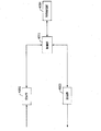
- FIG. 2 is a schematic block diagram showing communication between each device of the communication system in the present embodiment.
- the communication system includes four base station apparatuses 10-1, 10-2, 10-3, and 10-4.
- the base station device 10 performs communication with the terminal device 20 using beamforming.
- the base station apparatus 10 communicates with the location server 40 using LPPa.
- the location server 40 can acquire the beam direction used by the base station apparatus 10 via LPPa.
- the beam direction can be a direction vector in the global coordinate system or a set of azimuth and elevation angles.
- the global coordinate system can be, for example, a right-handed coordinate system in which the x axis is the east direction, the y axis is the north direction, and the z axis is the zenith direction.
- the terminal device 20 communicates with the location server 40 by LPP.
- the terminal device 20 can receive the direction of the transmission beam used by the base station device 10 from the location server 40 via LPP.
- the terminal device 20 may receive the position of the base station device 10 from the location server 40. In this case, the terminal device 20 can estimate the direction from the base station device 10 to the terminal device 20 by measuring the position of the terminal device.
- FIG. 3 is a diagram illustrating an example where the base station apparatus 10 and the terminal apparatus 20 determine beams using beam sweeping.
- a reference signal positioning reference signal, channel state information reference signal, cell-specific reference signal, etc.
- a synchronization signal can be used.
- the base station antenna 100 includes base station beam candidates 101-1, 101-2, 101-3, and 101-4.
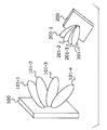
- the terminal antenna 200 includes terminal beam candidates 201-1, 201-2, 201-3, and 201-4.
- the base station apparatus 10 can transmit a signal to the terminal apparatus 20 using the base station beam candidate 101-1 as a transmission beam.
- the terminal apparatus 20 can receive signals from the base station apparatus 10 using the terminal beam candidates 201-1, 201-2, 201-3, and 201-4 as reception beams.
- the terminal device 20 includes, among the terminal beam candidates 201-1, 201-2, 201-3, and 201-4, SNR (Signal to Noise Ratio), beam gain, RSRP (Reference Signal Received Power).
- a beam candidate having the maximum RSRQ (Reference Signal Received Quality) or the like can be used as a received beam.
- the transmission beam of the base station beam candidate 101-m base station apparatus 10 when the SNR is maximized the terminal beams candidate 201-n
- the reception beam of the terminal device 20 can be used.
- the number of base station beam candidates and terminal beam candidates has been described as four, but it may be more or less.
- the base station apparatus 10 performs transmission and the terminal apparatus 20 performs reception.
- the terminal apparatus 20 may perform transmission and the base station apparatus 10 may perform reception.
- the m base station beam candidates described above may be all beam candidates that the base station apparatus 10 is capable of, or may be some beam candidates.
- n terminal beam candidates may be all beam candidates that the terminal device 20 is capable of, or may be some beam candidates.
- the beam candidate described above may be a horizontal beam or a vertical beam.
- the base station apparatus 10 / terminal apparatus 20 searches for a suitable horizontal beam and vertical beam, respectively.
- the vertical direction of the antenna is also called a first dimension
- the horizontal direction of the antenna is also called a second dimension.
- the base station apparatus 10 reports the base station beam direction in the global coordinate system of the determined base station beam candidate to the location server 40 via LPPa.
- the location server 40 notifies the base station beam direction to the terminal device 20 via LPP.
- FIG. 4 is a diagram illustrating a relationship between the base station apparatus 10-m and the terminal antenna 200 of the terminal apparatus 20.
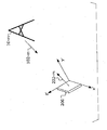
- the terminal antenna 200 is a planar antenna on a plane formed by the x ′ axis and the z ′ axis of the local coordinate system of the terminal 20.
- the base station beam direction 102-m and the terminal beam direction 202-m can be determined by the beam sweeping described above.
- the attitude of the terminal device 20 is estimated by estimating a rotation matrix from the global coordinate system to the local coordinate system of the terminal device 20 will be described.
- M be the number of base station devices.
- C (c 1 ,..., C M ) Become.
- a quaternion can be expressed as the sum of a scalar and a three-dimensional vector.
- a right-handed screw rotation at an angle ⁇ about a certain direction vector n can be represented by a quaternion of cos (0.5 ⁇ ) + nsin (0.5 ⁇ ).
- the matrix M described above is used. Let p p and q column components of the matrix M be m pq . Next, a 4 ⁇ 4 matrix N as shown in the following equation (1) is calculated.
- N is an eigenvalue decomposition and the normalized eigenvector of size 4 corresponding to the maximum eigenvalue is b.
- a quaternion is expressed by the sum of a scalar and a three-dimensional vector
- a quaternion to be obtained is obtained by using a quaternion in which the first component of the vector b is a scalar part and the three-dimensional vector consisting of the second, third and fourth components of the vector b is a vector part. It becomes.
- FIG. 5 is a schematic block diagram illustrating a configuration example of the base station apparatus 10 in the present embodiment.
- the base station apparatus 10 includes an upper layer processing unit (upper layer processing step) 1001, a control unit (control step) 1002, a transmission unit (transmission step) 1003, a reception unit (reception step) 1004, A signal generation unit (physical signal generation step) 10031, a transmission beam setting unit (transmission beam setting step) 10032, a radio reception unit (radio reception step) 10041, and a beam information reception unit (beam information reception step) 10044 are configured.
- the transmission unit 1003 may include a transmission antenna.
- the receiving unit 1005 may include a receiving antenna. The transmitting antenna and the receiving antenna may be the same antenna.
- the upper layer processing unit 1001 includes a medium access control (Medium Access Control: MAC) layer, a packet data integration protocol (Packet Data Convergence Protocol: PDCP) layer, a radio link control (Radio Link Control: RLC) layer, a radio resource control (Radio) Resource (Control: RRC) layer processing. Further, upper layer processing section 1001 generates information necessary for controlling transmission section 1003 and reception section 1004 and outputs the information to control section 1002.
- Medium Access Control: MAC Medium Access Control
- PDCP Packet Data Convergence Protocol
- RLC Radio Link Control
- Radio Radio Resource
- the upper layer processing unit 1001 receives information related to the terminal device such as the function (UE capability) of the terminal device from the terminal device. In other words, the terminal apparatus transmits its own function to the base station apparatus using an upper layer signal.
- information on a terminal device includes information indicating whether the terminal device supports a predetermined function, or information indicating that the terminal device has introduced a predetermined function and has completed a test.
- whether or not to support a predetermined function includes whether or not installation and testing for the predetermined function have been completed.
- the terminal device transmits information (parameters) indicating whether the predetermined function is supported.
- the terminal device does not transmit information (parameter) indicating whether or not the predetermined device is supported. That is, whether or not to support the predetermined function is notified by whether or not information (parameter) indicating whether or not to support the predetermined function is transmitted.
- Information (parameter) indicating whether or not a predetermined function is supported may be notified using 1 or 1 bit.
- the upper layer processing unit 1001 generates or acquires downlink data (transport block), system information, RRC message, MAC CE, and the like from the upper node. Upper layer processing section 1001 outputs downlink data to transmitting section 1003 and outputs other information to control section 1002. The upper layer processing unit 1001 manages various setting information of the terminal device.
- the upper layer processing unit 1001 determines the frequency and subframe to which the physical channel is allocated, the coding rate and modulation scheme (or MCS) of the physical channel, transmission power, and the like.
- the upper layer processing unit 1001 outputs the determined information to the control unit 1002.
- the upper layer processing unit 1001 generates information used for physical channel scheduling based on the scheduling result.
- the upper layer processing unit 1001 outputs the generated information to the control unit 1002.
- the control unit 1002 generates a control signal for controlling the transmission unit 1003 and the reception unit 1004 based on the information input from the higher layer processing unit 1001.
- the control unit 1002 generates downlink control information based on the information input from the higher layer processing unit 1001 and outputs the downlink control information to the transmission unit 1003.
- the transmission unit 1003 generates a downlink reference signal according to the control signal input from the control unit 1002, and encodes the HARQ indicator, the downlink control information, and the downlink data input from the higher layer processing unit 1001. Then, it modulates, multiplexes the downlink physical channel and the downlink reference signal, and transmits the signal to the terminal apparatus 20 via the transmission / reception antenna.
- the physical signal generation unit 10031 generates an OFDM (Orthogonal Frequency Division Multiplexing) signal from the HARQ indicator, the downlink control information, the downlink reference signal, and the downlink data input from the higher layer processing unit 1001.
- the OFDM signal is added with a cyclic prefix (CP) to generate a baseband digital signal.
- the baseband digital signal is converted into an analog signal, an extra frequency component is removed by filtering, upconverted to a carrier frequency, power amplified, and transmitted from a transmitting antenna.
- the generated signal is not limited to the OFDM signal, and may be a single carrier signal, a CDMA (Code Division Multiple Access) signal, or the like.
- the transmission beam setting unit 10032 sets a transmission beam used by the base station apparatus 10.
- the transmission beam setting unit 10032 can set a transmission beam using beam sweeping.
- a transmission beam candidate having a maximum SNR in the terminal device 20 and received by a beam information receiving unit 10042 described later can be used as a transmission beam.
- the transmission beam setting unit 10032 can report the direction of the set transmission beam in the global coordinate system to the location server 40 via the upper layer processing unit 1001. Information relating to the direction of the transmit beam can be referred to as transmit beam information.
- Radio receiving section 10040 separates, demodulates and decodes the received signal received from the terminal device in accordance with the control signal input from control section 1002, and outputs the decoded information to upper layer processing section 1001 or beam information receiving section 10042. .
- the radio reception unit 10041 converts the uplink signal received via the reception antenna into a baseband signal by down-conversion, removes unnecessary frequency components, and amplifies the signal level so that the signal level is properly maintained. And quadrature demodulation based on the in-phase and quadrature components of the received signal, and converting the quadrature demodulated analog signal into a digital signal.
- the wireless receiving unit 10040 removes a part corresponding to the CP from the converted digital signal.
- the wireless reception unit 10041 performs Fast Fourier Transform (FFT) on the signal from which the CP is removed, and extracts a signal in the frequency domain.
- FFT Fast Fourier Transform
- the extracted frequency domain signals are separated into signals such as uplink physical channels and uplink reference signals.
- the radio receiver unit 10041 performs inverse discrete Fourier transform (Inverse Fourier Transform: IDFT) on PUSCH / NPUSCH, acquires a modulation symbol, and demodulates the received signal. Note that IFFT corresponding to the number of points of the inverse discrete Fourier transform may be used.
- IDFT inverse discrete Fourier transform
- Radio receiving section 10041 decodes the demodulated coded bits at a coding rate that is determined in advance according to a predetermined encoding method or that is notified to terminal device 20 by uplink grant in advance by the device itself.
- the decoded uplink data and the uplink control information are output to the higher layer processing unit 1001.
- decoding is performed using the coded bits held in the HARQ buffer input from higher layer processing section 1001 and the demodulated coded bits.
- the beam information receiving unit 10042 receives beam information from the terminal device 20 necessary for the transmission beam setting unit 10032 to set a transmission beam.
- the beam information is, for example, transmission beam identification information that maximizes the SNR measured by the terminal device 20 when beam sweeping is performed.
- the identification information may be, for example, a transmission beam number (transmission beam index) or a resource number (resource index).
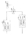
- FIG. 6 is a schematic block diagram showing the configuration of the terminal device 20 in the present embodiment.
- the terminal device 20 includes an upper layer processing unit (upper layer processing step) 2001, a control unit (control step) 2002, a transmission unit (transmission step) 2003, and a reception unit (reception step) 2004.
- the transmission unit 2003 includes a physical signal generation unit (physical signal generation step) 20003, a beam information generation unit (beam information generation step) 20032, a local direction setting unit (second direction setting unit, local direction setting step, second Direction setting step) 20033.
- the receiving unit 2004 includes a wireless receiving unit (wireless receiving step) 20041, a global direction setting unit (first direction setting unit, global direction setting step, first direction setting step) 20042, posture measuring unit (posture measuring step). ) 20044.
- the upper layer processing unit 2001 outputs uplink data (transport block) generated by a user operation or the like to the transmission unit 2003.
- the upper layer processing unit 2001 includes a medium access control (Medium Access Control: MAC) layer, a packet data integration protocol (Packet Data Convergence Protocol: PDCP) layer, a radio link control (Radio Link Control: RLC) layer, and a radio resource control. Process (Radio Resource Control: RRC) layer etc.
- Medium Access Control Medium Access Control: MAC
- PDCP Packet Data Convergence Protocol
- RLC Radio Link Control
- RRC Radio Resource Control
- the upper layer processing unit 2001 outputs information indicating the function of the terminal device supported by the own terminal device to the transmission unit 2003.
- the upper layer processing unit 2001 manages various setting information of the terminal device itself. Also, the upper layer processing unit 2001 generates information arranged in each uplink channel and outputs the information to the transmission unit 2003.
- the upper layer processing unit 2001 interprets downlink control information received via the receiving unit 2004 and determines scheduling information. Further, upper layer processing section 2001 generates control information for controlling receiving section 2004 and transmitting section 2003 based on the scheduling information, and outputs the control information to control section 2002.
- the upper layer processing unit 2001 interprets data (information) necessary for attitude measurement, such as direction information of the transmission beam of the base station apparatus 10-m, from the location server 40, and outputs the data (information) to the control unit 2002.
- the control unit 2002 generates a control signal for controlling the receiving unit 2004 and the transmitting unit 2003 based on the information input from the higher layer processing unit 2001.
- the control unit 2002 outputs the generated control signal to the receiving unit 2004 and the transmitting unit 2003 to control the receiving unit 2004 and the transmitting unit 2003.
- the receiving unit 2004 separates, demodulates, and decodes the received signal received from the base station apparatus via the receiving antenna according to the control signal input from the control unit 2002, and outputs the decoded information to the higher layer processing unit 2001. .
- the radio reception unit 20041 converts the downlink signal received via the transmission / reception antenna into a baseband signal by down-conversion, removes unnecessary frequency components, and sets the amplification level so that the signal level is properly maintained. Based on the in-phase component and the quadrature component of the received signal, the signal is quadrature demodulated, and the quadrature demodulated analog signal is converted into a digital signal.
- the wireless reception unit 20041 removes a portion corresponding to CP from the converted digital signal, performs fast Fourier transform on the signal from which CP is removed, and extracts a frequency domain signal.
- the extracted signal is separated into a downlink physical channel and a downlink reference signal.
- Radio receiving section 20041 performs channel compensation of the downlink physical channel based on the channel estimation value of the desired signal obtained from the channel measurement, detects downlink control information, and outputs the downlink control information to control section 2002.
- the wireless reception unit 20009 detects a signal using the channel estimation value and outputs the signal to the higher layer processing unit 2001.
- the wireless receiving unit 20041 sets a reception beam. For example, beam sweeping is performed with the base station apparatus 10-m, and a beam having the maximum SNR is set as a reception beam. Information relating to the direction of the receive beam can be referred to as receive beam information.
- the global direction setting unit 20042 sets a global direction vector, which is a direction vector in the global coordinate system from the base station apparatus 10-m to the terminal apparatus 20, based on the direction of the transmission beam.
- the global direction setting unit 20042 outputs the set global direction vector to the posture measurement unit 20044.
- the local direction setting unit 20043 sets a local direction vector which is a direction vector in the local coordinate system of the reception beam set by the wireless reception unit 20041.
- the local direction setting unit 20043 outputs the set local direction vector to the posture measurement unit 20044.
- the attitude measurement unit 20044 measures the attitude of the terminal device based on the global direction input from the global direction setting unit 20042 and the local direction input from the local direction setting unit 20043.
- the attitude measurement unit 20044 may receive beam attitude measurement information from the location server 40 indicating whether or not to use the transmission beam for attitude measurement. For example, when the transmission beam used by the base station apparatus 10-m is received by the reception beam of the terminal apparatus 20 through reflection, it is desirable to remove this transmission beam from the attitude measurement. By using the transmission beam indicated by the beam attitude measurement information, the accuracy of attitude measurement can be improved.
- the transmission unit 2003 generates an uplink reference signal according to the control signal input from the control unit 2002, encodes and modulates the uplink data (transport block) input from the higher layer processing unit 2001, and controls the control channel.
- the uplink physical channel such as the shared channel and the generated uplink reference signal are multiplexed and transmitted to the base station apparatus via the transmission antenna.
- the physical signal generation unit 20003 generates an SC-FDMA symbol from the uplink control information, the uplink data, and the uplink reference signal.
- a CP is added to the SC-FDMA symbol to generate a baseband digital signal.
- the baseband digital signal is converted to an analog signal, an extra frequency component is removed, converted to a carrier frequency by up-conversion, power amplified, and transmitted.
- the terminal device is not limited to the SC-FDMA system, and can perform modulation of the OFDMA system or the CDMA system.
- FIG. 7 is a schematic block diagram illustrating a configuration example of the location server 40.
- the location server 40 includes a control unit (control step) 4001, a reception unit (reception step) 4002, a transmission unit (transmission step) 4003, and a direction management unit (direction management step) 4004.
- the control unit 4001 controls the reception unit 4002, the transmission unit 4003, and the direction management unit 4004.
- the receiving unit 4002 receives the direction of the transmission beam used by the base station device 10-m for the terminal device 20, and outputs the direction to the control unit 4001.
- the reception unit 4002 receives transmission beam identification information used by the base station device 10-m for the terminal device 20, and outputs it to the control unit 4001.
- the control unit 4001 outputs the direction of the transmission beam or the identification information of the transmission beam to the direction management unit 4004.
- the direction management unit 4004 receives and stores the direction of the transmission beam.
- the direction management unit 4004 receives the identification information of the transmission beam, determines the direction of the transmission beam based on the transmission beam and direction related information in the base station apparatus 10-m, and stores it.
- Direction management section 4004 outputs the direction of the transmission beam of base station apparatus 10-m to control section 4001 as information addressed to terminal apparatus 20.
- the direction management unit 4004 may estimate the position of the terminal device 20. For example, assuming that the position of the base station apparatus 10-m is known, the position of the terminal apparatus 20 can be calculated from the direction of each transmission beam. At that time, it can be determined whether or not each transmission beam is reflected. If it is determined that the beam is reflected, the beam attitude measurement information indicating whether or not the transmission beam is used for attitude measurement can be rejected and output to the control unit 4001 as information addressed to the terminal device 20.
- the control unit 4001 outputs the direction of the transmission beam of the base station device 10-m to the transmission unit 4003 as information addressed to the terminal device 20.
- the transmission unit 4003 transmits the direction of the transmission beam of the base station apparatus 10-m as information addressed to the terminal apparatus 20. The same applies to the beam attitude measurement information.
- the terminal device can measure the attitude of the terminal device with high accuracy.
- the terminal apparatus measures the attitude of the terminal apparatus based on the direction of the transmission beam of the base station apparatus and the direction of the reception beam used by the terminal apparatus received from the location server.
- the terminal device reports the direction of the reception beam to the location server and the location server estimates the attitude of the terminal device will be described.
- the configuration of the base station apparatus 10 in this embodiment is the same as that in FIG. However, the operation of the beam information receiving unit 10042 is different.
- the beam information receiving unit 10044 receives the direction of the reception beam used by the terminal device 20. The received direction information is transmitted to the location server 40 via the control unit 1002 and the upper layer processing unit 1001.
- FIG. 8 is a schematic block diagram showing a configuration example of the terminal device 20 in the present embodiment. Comparing FIG. 8 with the terminal device 20 (FIG. 6) in the first embodiment, there is no global direction setting unit 20042, local direction setting unit 20043, and posture measuring unit 20044, and posture receiving unit (posture receiving step) 20045 is provided. Exists.
- the posture receiving unit 20045 receives the posture of the terminal device 20 calculated by the location server 40. This reception process may be performed via the upper layer processing unit 2001 and the control unit 2002.
- the operation of the beam information generation unit 20032 is different from that of the first embodiment.
- the beam information generation unit 20032 generates the direction of the reception beam for the base station device 10-m used by the terminal device 20, and transmits the direction through the transmission unit 2003.
- FIG. 9 is a schematic block diagram showing a configuration example of the location server 40 in the present embodiment.
- the reception unit 4002 receives the direction of the reception beam used by the terminal device 20 for the base station device 10-m and outputs the received beam direction to the control unit 4001.
- the direction management unit 4004 receives the direction of the transmission beam used by the base station device 10-m for the terminal device 20, and outputs it to the control unit 4001.
- the direction management unit 4004 includes a global direction setting unit (first direction setting unit, global direction setting step, first direction setting step) 40041, a local direction setting unit (second direction setting unit, local direction setting step). , Second direction setting step) 40042.
- Global direction setting section 40041 sets the first direction, which is the direction vector of the transmission beam of base station apparatus 10-m in the global coordinate system, based on the direction of the transmission beam input from control section 4001.
- the first direction may be the direction of the terminal device 20 with respect to the base station device 10-m.
- the local direction setting unit 40042 sets a second direction that is a direction vector of the reception beam in the local coordinate system of the terminal device 20 based on the direction of the reception beam input from the control unit 4001.
- the second direction may be the direction of base station apparatus 10-m with respect to terminal apparatus 20.
- the direction management unit 4004 measures the attitude of the terminal device 20 based on the first direction and the second direction. This measurement may be performed excluding the transmission beam and reception beam pairs via reflection.
- the direction management unit 4004 outputs the measured posture to the control unit 4001.
- the transmission unit 4003 transmits the attitude of the terminal device 20 as information addressed to the terminal device 20.
- the location server can measure the attitude of the terminal device with high accuracy by using the direction of the transmission beam and the direction of the reception beam.
- the terminal device can receive a highly accurate posture.
- the direction of the transmission beam / the direction of the reception beam is estimated by beam sweeping.
- one embodiment of the present invention is not limited thereto, and the direction / reception of the transmission beam is estimated by arrival direction estimation.
- the direction of the beam may be estimated.
- a program that operates in the terminal device, the location server, and the method in the terminal device according to one aspect of the present invention is a program that controls a CPU or the like so as to realize the function of the above-described embodiment according to one aspect of the present invention ( Computer program).
- Information handled by these devices is temporarily stored in the RAM at the time of processing, then stored in various ROMs and HDDs, read out by the CPU, and corrected and written as necessary.
- a recording medium for storing the program a semiconductor medium (for example, ROM, nonvolatile memory card, etc.), an optical recording medium (for example, DVD, MO, MD, CD, BD, etc.), a magnetic recording medium (for example, magnetic tape, Any of a flexible disk etc. may be sufficient.
- the program when distributing to the market, can be stored and distributed on a portable recording medium, or transferred to a server computer connected via a network such as the Internet.
- the storage device of the server computer is also included in one embodiment of the present invention.
- Each functional block of the receiving apparatus may be individually formed as a chip, or a part or all of them may be integrated into a chip. When each functional block is integrated, an integrated circuit controller for controlling them is added.
- the method of circuit integration is not limited to LSI, and may be realized by a dedicated circuit or a general-purpose processor.
- an integrated circuit based on the technology can also be used.
- the present invention is not limited to the above-described embodiment.
- the video generation method according to an aspect of the present invention is not limited to the application to the glasses-type terminal, and it is needless to say that the video generation method can be applied to a portable device or a wearable device.
- One embodiment of the present invention is suitable for a terminal device, a location server, and a method in a terminal device.
- One embodiment of the present invention is used in, for example, a communication system, a communication device (for example, a mobile phone device, a base station device, a wireless LAN device, or a sensor device), an integrated circuit (for example, a communication chip), a program, or the like. be able to.
- Base station apparatus 100 Base station antennas 101-1, 101-2, 101-3, 101-4 Base station beam candidates 102-m Base station beam direction 1001 Upper layer processing unit 1002 Control unit 1003 Transmission unit 10031 Physical signal generation unit 10032 Transmission beam setting unit 1004 Reception unit 10041 Radio reception unit 10042 Beam information reception unit 20 Terminal device 200 Terminal antennas 201-1 and 201-2 201-3, 201-4 Terminal beam candidates 202-m Terminal beam direction 2001 Upper layer processing unit 2002 Control unit 2003 Transmitting unit 20031 Physical signal generating unit 20032 Beam information generating unit 2004 Receiving unit 20041 Radio receiving unit 20042 Global direction setting unit 20043 Local direction setting unit 20044 Posture Tough 20045 posture receiver 30 core network 40 location server 4001 the control section 4002 receiving unit 4003 transmission 4004 direction management unit 40041 global direction setting unit 40042 local direction setting unit
Landscapes
- Engineering & Computer Science (AREA)
- Computer Networks & Wireless Communication (AREA)
- Signal Processing (AREA)
- Physics & Mathematics (AREA)
- General Physics & Mathematics (AREA)
- Radar, Positioning & Navigation (AREA)
- Remote Sensing (AREA)
- Mobile Radio Communication Systems (AREA)
Abstract
端末装置(20)は、送信装置(10-m)が用いる送信ビームの情報である送信ビーム情報を受信し、第1の座標系における前記送信ビームの方向ベクトルである第1の方向(102-m)を、前記送信ビーム情報に基づいて設定する第1の方向設定部と、前記送信装置から信号の受信に用いる受信ビームを設定する無線受信部と、第2の座標系における前記受信ビームの方向ベクトルである第2の方向(202-m)を設定する第2の方向設定部と、前記第1の方向(102-m)と前記第2の方向(202-m)とに基づいて、自身の姿勢を測定する姿勢測定部と、を備える。
Description
本発明は、端末装置、ロケーションサーバおよび端末装置における方法に関する。
本願は、2017年5月11日に日本に出願された特願2017-94569号について優先権を主張し、その内容をここに援用する。
本願は、2017年5月11日に日本に出願された特願2017-94569号について優先権を主張し、その内容をここに援用する。
3GPP(Third Generation Partnership Project)によって仕様策定されたLTE(Long Term Evolution)、LTE-A(LTE-Advanced)のような通信システムでは、基地局装置(基地局、送信局、送信点、下りリンク送信装置、上りリンク受信装置、送信アンテナ群、送信アンテナポート群、コンポーネントキャリア、eNodeB、アクセスポイント、AP、送信装置)或いは基地局装置に準じる送信局がカバーするエリアをセル(Cell)状に複数配置するセルラ構成とすることにより、通信エリアを拡大することができる。基地局装置には、端末装置(受信局、受信点、下りリンク受信装置、上りリンク送信装置、受信アンテナ群、受信アンテナポート群、UE、ステーション、STA)が接続する。このセルラ構成において、隣接するセルまたはセクタ間で同一周波数を利用することで、周波数利用効率を向上させることができる。今後は、さらなるデータ・レート向上のため、ミリ波等の高周波数帯を用いた通信が仕様策定されていく予定である。高周波数帯での通信では、ビームフォーミングが前提とされる。ビームスウィーピングによるビームフォーミングの運用方法が、特許文献1に記載されている。
また、LTEやLTE-Aでは、端末の位置推定を行う方法が仕様化されている。今後は高周波数帯を用いた位置推定も導入されていくと考えられる。60GHz帯の信号を用いた位置推定の方法が、非特許文献1に記載されている。
一方、近年、AR(Augmented Reality、拡張現実)、VR(Virtual Reality、仮想現実)、ロボットといった分野が急速に拡大している。このような分野では、AR/VRの端末やロボットの位置のみならず姿勢を高精度に推定する必要がある。
しかしながら、非特許文献1に記載の位置推定方法では、端末の姿勢を推定することはできないという問題がある。
本発明の一態様はこのような事情を鑑みてなされたものであり、その目的は、端末の姿勢を高精度に推定できる端末装置、ロケーションサーバおよび端末装置における方法を提供することにある。
上述した課題を解決するために本発明の一態様に係る端末装置、ロケーションサーバおよび端末装置における方法の構成は、次の通りである。
本発明の一態様による端末装置は、送信装置が用いる送信ビームの情報である送信ビーム情報を受信し、第1の座標系における前記送信ビームの方向ベクトルである第1の方向を、前記送信ビーム情報に基づいて設定する第1の方向設定部と、前記送信装置から信号の受信に用いる受信ビームを設定する無線受信部と、第2の座標系における前記受信ビームの方向ベクトルである第2の方向を設定する第2の方向設定部と、前記第1の方向と前記第2の方向とに基づいて、自身の姿勢を測定する姿勢測定部と、を備える。
また、本発明の一態様による端末装置において、前記送信ビーム情報は、前記送信装置が用いる送信ビームの前記第1の座標系における方位角と仰角であり、前記第1の方向設定部は、前記方位角と前記仰角に基づいて前記第1の方向を設定する。
また、本発明の一態様による端末装置において、前記送信ビーム情報は、前記送信装置が用いる送信ビームの前記第1の座標系における方向ベクトル であり、前記第1の方向設定部は、前記方向ベクトルに基づいて前記第1の方向を設定する。
また、本発明の一態様による端末装置において、前記第2の座標系は、前記姿勢に固定された座標系である。
また、本発明の一態様による端末装置において、前記姿勢測定部は、前記送信ビームを姿勢測定に用いるか否かを示す、ビーム姿勢測定情報を受信し、前記姿勢測定部は、前記ビーム姿勢測定情報が指示する前記送信ビームに対応する、前記第1の方向と前記第2の方向とに基づいて前記測定を行う。
本発明の一態様によるロケーションサーバは、複数の基地局装置と端末装置がビームフォーミングを用いて通信を行うシステムにおけるロケーションサーバであって、前記基地局装置が用いる送信ビームの情報である送信ビーム情報と、前記端末装置が用いる受信ビームの情報である受信ビーム情報とを受信する受信部と、第1の座標系における前記送信ビームの方向ベクトルである第1の方向を、前記送信ビーム情報に基づいて設定する第1の方向設定部と、前記端末装置の第2の座標系における前記受信ビームの方向ベクトルである第2の方向を、前記受信ビーム情報に基づいて設定する第2の方向管理部と、前記第1の方向と前記第2の方向とに基づいて、前記端末装置の姿勢を測定する方向管理部と、を備える。
また、本発明の一態様によるロケーションサーバにおいて、前記送信ビーム情報と前記受信ビーム情報は、前記送信ビームと前記受信ビームの前記第1の座標系における方位角と仰角であり、前記第1の方向設定部は、前記方位角と前記仰角に基づいて、前記第1の方向を設定し、前記第2の方向設定部は、前記方位角と前記仰角に基づいて、前記第2の方向を設定する。
また、本発明の一態様によるロケーションサーバにおいて、前記送信ビーム情報と前記受信ビーム情報は、前記送信ビームと前記受信ビームの前記第1の座標系におけるベクトルであり、前記第1の方向設定部は、前記ベクトルに基づいて、前記第1の方向を設定し、前記第2の方向設定部は、前記ベクトルに基づいて、前記第2の方向を設定する。
また、本発明の一態様によるロケーションサーバにおいて、前記方向管理部は、前記送信ビームと前記受信ビームとが、反射を介しているか否かを推定し、前記反射を介していない前記送信ビームと前記受信ビームにおける第1の方向と第2の方向に基づいて、前記姿勢を測定する。
本発明の一態様による方法は、複数の送信装置とビームフォーミングを用いて通信する端末装置における方法であって、前記送信装置が用いる送信ビームの情報である送信ビーム情報を受信し、第1の座標系における前記送信ビームの方向ベクトルである第1の方向を、前記送信ビーム情報に基づいて設定する第1の方向設定過程と、前記送信装置から信号の受信に用いる受信ビームを設定する無線受信過程と、第2の座標系における前記受信ビームの方向ベクトルである第2の方向を設定する第2の方向設定過程と、前記第1の方向と前記第2の方向とに基づいて、自身の姿勢を測定する姿勢測定過程と、を備える。
本発明の一又は複数の態様によれば、端末装置は、自身の姿勢を高精度に推定することができる。
(第1の実施形態)
本実施形態における通信システムは、基地局装置(送信装置、セル、送信点、送信アンテナ群、送信アンテナポート群、コンポーネントキャリア、eNodeB、アクセスポイント)、端末装置(端末、移動端末、受信点、受信端末、受信装置、受信アンテナ群、受信アンテナポート群、UE、ステーション)及びロケーションサーバを備える。ロケーションサーバは、例えばE-SMLC(Enhanced Serving Mobile Location Centre)、SUPL(Secure User Plane Location)、SLP(SUPL Location Platform)を含む。また端末装置と接続している(無線リンクを確立している)基地局装置をサービングセルと呼ぶ。
本実施形態における通信システムは、基地局装置(送信装置、セル、送信点、送信アンテナ群、送信アンテナポート群、コンポーネントキャリア、eNodeB、アクセスポイント)、端末装置(端末、移動端末、受信点、受信端末、受信装置、受信アンテナ群、受信アンテナポート群、UE、ステーション)及びロケーションサーバを備える。ロケーションサーバは、例えばE-SMLC(Enhanced Serving Mobile Location Centre)、SUPL(Secure User Plane Location)、SLP(SUPL Location Platform)を含む。また端末装置と接続している(無線リンクを確立している)基地局装置をサービングセルと呼ぶ。
本実施形態における基地局装置及び端末装置は、免許が必要な周波数帯域(ライセンスバンド)及び/又は免許不要の周波数帯域(アンライセンスバンド)で通信することができる。
本実施形態において、“X/Y”は、“XまたはY”の意味を含む。本実施形態において、“X/Y”は、“XおよびY”の意味を含む。本実施形態において、“X/Y”は、“Xおよび/またはY”の意味を含む。
図1は、本実施形態に係る通信システムの例を示す図である。図1に示すように、本実施形態における通信システムは、基地局装置10-1、10-2、10-3、10-4、端末装置20、コアネットワーク30、ロケーションサーバ40を含む。基地局装置10-1、10-2、10-3、10-4は、端末装置20と無線通信する。また、基地局装置10-1、10-2、10-3、10-4は、コアネットワーク30を介してロケーションサーバ40と接続されている。ロケーションサーバ40は、端末装置20の位置推定と姿勢推定をサポートすることができる。ここで、姿勢とは、例えばグローバル座標系における端末装置20の向き(方向)である。なお姿勢は、グローバル座標系に限らず、基地局装置10及び/又はロケーションサーバ40と端末装置20が共有している座標系における端末装置20の向きであってもよい。後述するように端末装置20とロケーションサーバ40とは、ポジショニングプロトコル(例えばLPP)による通信を行うが、この通信は、基地局装置10-1、10-2、10-3、10-4と、コアネットワーク30とにより中継される。また、ロケーションサーバ40と基地局装置10-1、10-2、10-3、10-4とは、ポジショニングプロトコルA(例えばLPPa)による通信を行うが、この通信は、コアネットワーク30により中継される。基地局装置10-1、10-2、10-3、10-4と端末装置20とは、ビームフォーミングを用いた通信が行われる。なお、基地局装置を4つとして説明したが、これより多くても良いし、少なくても良い。
図2は、本実施形態における通信システムの各装置間の通信を示す概略ブロック図である。図1において、通信システムは、4つの基地局装置10-1、10-2、10-3、10-4を含んでいるが、図2における基地局装置10は、これら4つの基地局装置10-1、10-2、10-3、10-4を代表している。図2に示すように、基地局装置10は、端末装置20とビームフォーミングを用いた通信を行う。基地局装置10は、ロケーションサーバ40とLPPaによる通信を行う。ロケーションサーバ40は、LPPaを介して、基地局装置10が用いるビームの方向を取得することができる。ここで、ビームの方向は、グローバル座標系における方向ベクトルか、または、方位角と仰角のセットとすることができる。グローバル座標系は、例えば、x軸を東方向、y軸を北方向、z軸を天頂方向とした右手座標系にすることができる。端末装置20は、ロケーションサーバ40とLPPによる通信を行う。端末装置20は、LPPを介して、基地局装置10が用いている送信ビームの方向を、ロケーションサーバ40から受信することができる。
なお、端末装置20は、基地局装置10の位置をロケーションサーバ40から、受信するようにしても良い。この場合、端末装置20が、自端末装置の位置を測定することで、基地局装置10から端末装置20への方向を推定することができる。
図3は、基地局装置10と端末装置20が、ビームスウィーピングを用いてビームを決定する場合の一例を示す図である。なおビームスウィーピングは、参照信号(ポジショニング参照信号、チャネル状態情報参照信号、セル固有参照信号など)や同期信号を用いることができる。図3において、基地局アンテナ100は、基地局ビーム候補101-1、101-2、101-3、101-4を備える。図3において、端末アンテナ200は、端末ビーム候補201-1、201-2、201-3、201-4を備える。例えば、基地局装置10は基地局ビーム候補101-1を送信ビームとし、端末装置20へ信号を送信することができる。その際、端末装置20は、端末ビーム候補201-1、201-2、201-3、201-4を受信ビームとして、基地局装置10からの信号を受信することができる。端末装置20は、端末ビーム候補201-1、201-2、201-3、201-4のうち、SNR(信号対雑音電力比、Signal to Noise Ratio)、ビームゲイン、RSRP(Reference Signal Received Power)、RSRQ(Reference Signal Received Quality)などが最大となるビーム候補を、受信ビームとすることができる。さらに、基地局装置10は、ビーム候補101-m(m=2、・・・4)を送信ビームとした信号送信を随時試すことができる。それぞれのmに対して、端末装置20は、SNRが最大となる受信ビームを、ビーム候補201-n(n=1、・・・、4)の中から選ぶことができる。以上の探索処理の結果、取りうる42通りの送受信ビームパターンの中から、SNRが最大となる場合の基地局ビーム候補101-mを基地局装置10の送信ビーム、端末ビーム候補201-nを端末装置20の受信ビームとすることができる。なお、上記の説明で、基地局ビーム候補と端末ビーム候補の数を4として説明したが、これより多くても良いし、少なくても良い。なお、上記の説明で、基地局装置10が送信、端末装置20が受信を行う場合について説明したが、端末装置20が送信、基地局装置10が受信を行っても良い。また、上述のm個の基地局ビーム候補は、基地局装置10が可能な全てのビーム候補であってもよいし、一部のビーム候補であってもよい。また、上述のn個の端末ビーム候補は、端末装置20が可能な全てのビーム候補であってもよいし、一部のビーム候補であってもよい。また、上述のビーム候補は、水平ビーム又は垂直ビームであってもよい。この場合、基地局装置10/端末装置20は、各々好適な水平ビーム及び垂直ビームを探索する。なお、以降の実施形態では、アンテナの垂直方向を第1の次元、アンテナの水平方向を第2の次元とも呼ぶ。
基地局装置10は、決定した基地局ビーム候補のグローバル座標系における基地局ビーム方向を、LPPaを介して、ロケーションサーバ40に報告する。ロケーションサーバ40は、基地局ビーム方向を端末装置20に、LPPを介して通知する。
図4は、基地局装置10-mと端末装置20の端末アンテナ200との間の関係を示す図である。図4において、端末アンテナ200は端末20のローカル座標系のx’軸とz’軸がなす平面上の平面アンテナである。基地局ビーム方向102-mと端末ビーム方向202-mは、上述したビームスウィーピング等で決定することができる。以下、グローバル座標系から端末装置20のローカル座標系への回転行列を推定することで、端末装置20の姿勢を推定する一例を説明する。グローバル座標系で基地局ビーム方向102-mを表すベクトルに-1を乗算した方向ベクトルをcmとし、端末装置20のローカル座標系で端末ビーム方向202-mを表すベクトルをemとする。基地局装置の数をMとする。なお、図1はM=4の場合の一例である。この場合、グローバル座標系における方向ベクトルcmをm=1、・・・、Mの順に並べた次元3×Mの行列をCとすると、C=(c1、・・・、cM)となる。同様に、ローカル座標系における方向ベクトルemをm=1、・・・、Mの順に並べた次元3×Mの行列をEとすると、E=(e1、・・・、eM)となる。次に、CとETを乗算した3×3の行列M=CETに対して、特異値分解を行った結果をUSVTとする。ただし、Tは転置を表し、Uは次元3×3の直交行列、Sは次元3×3の対角行列、VTは次元3×3の直交行列である。このとき、グローバル座標系からローカル座標系への回転行列Rは、R=Vdiag[1、1、det(VUT)]UTのように推定できる。ただし、diag()は、引数を対角に並べた対角行列を表し、det()は引数の行列の行列式を表す。
次に、グローバル座標系からローカル座標系へのクォータニオンを推定することで、端末装置20の姿勢を推定する一例を説明する。クォータニオンはスカラーと3次元ベクトルの和で表現することができる。ある方向ベクトルnを軸にした角度θの右ねじ回転を、cos(0.5θ)+nsin(0.5θ)というクォータニオンで表すことができる。この場合も上述した行列Mを用いる。行列Mのp行q列成分をmpqとする。次に、次式(1)のような次元4×4の行列Nを計算する。

Nを固有値分解し、その最大固有値に対応するサイズ4の正規化された固有ベクトルをbとする。クォータニオンをスカラーと3次元ベクトルの和で表現する場合、ベクトルbの第1成分をスカラー部、ベクトルbの第2、3、4成分からなる3次元ベクトルをベクトル部としたクォータニオンが、求めるべきクォータニオンとなる。
図5は、本実施形態における基地局装置10の構成例を示す概略ブロック図である。図5に示すように、基地局装置10は、上位層処理部(上位層処理ステップ)1001、制御部(制御ステップ)1002、送信部(送信ステップ)1003、受信部(受信ステップ)1004、物理信号生成部(物理信号生成ステップ)10031、送信ビーム設定部(送信ビーム設定ステップ)10032、無線受信部(無線受信ステップ)10041、ビーム情報受信部(ビーム情報受信ステップ)10042を含んで構成される。なお、図示していないが、送信部1003は送信アンテナを含んでも良い。また、図示していないが、受信部1005は受信アンテナを含んでも良い。また、送信アンテナと受信アンテナは同じアンテナであってもよい。
上位層処理部1001は、媒体アクセス制御(Medium Access Control: MAC)層、パケットデータ統合プロトコル(Packet Data Convergence Protocol: PDCP)層、無線リンク制御(Radio Link Control: RLC)層、無線リソース制御(Radio Resource Control: RRC)層の処理を行なう。また、上位層処理部1001は、送信部1003および受信部1004の制御を行なうために必要な情報を生成し、制御部1002に出力する。
上位層処理部1001は、端末装置の機能(UE capability)等、端末装置に関する情報を端末装置から受信する。言い換えると、端末装置は、自身の機能を基地局装置に上位層の信号で送信する。
なお、以下の説明において、端末装置に関する情報は、その端末装置が所定の機能をサポートするかどうかを示す情報、または、その端末装置が所定の機能に対する導入およびテストの完了を示す情報を含む。なお、以下の説明において、所定の機能をサポートするかどうかは、所定の機能に対する導入およびテストを完了しているかどうかを含む。
例えば、端末装置が所定の機能をサポートする場合、その端末装置はその所定の機能をサポートするかどうかを示す情報(パラメータ)を送信する。端末装置が所定の機能をサポートしない場合、その端末装置はその所定の機能をサポートするかどうかを示す情報(パラメータ)を送信しない。すなわち、その所定の機能をサポートするかどうかは、その所定の機能をサポートするかどうかを示す情報(パラメータ)を送信するかどうかによって通知される。なお、所定の機能をサポートするかどうかを示す情報(パラメータ)は、1または0の1ビットを用いて通知してもよい。
上位層処理部1001は、下りリンクデータ(トランスポートブロック)、システムインフォメーション、RRCメッセージ、MAC CEなどを生成、又は上位ノードから取得する。上位層処理部1001は、下りリンクデータを送信部1003に出力し、他の情報を制御部1002に出力する。また、上位層処理部1001は、端末装置の各種設定情報の管理をする。
上位層処理部1001は、物理チャネルを割り当てる周波数およびサブフレーム、物理チャネルの符号化率および変調方式(あるいはMCS)および送信電力などを決定する。上位層処理部1001は、決定した情報を制御部1002に出力する。
上位層処理部1001は、スケジューリング結果に基づき、物理チャネルのスケジューリングに用いられる情報を生成する。上位層処理部1001は、生成した情報を制御部1002に出力する。
制御部1002は、上位層処理部1001から入力された情報に基づいて、送信部1003および受信部1004の制御を行なう制御信号を生成する。制御部1002は、上位層処理部1001から入力された情報に基づいて、下りリンク制御情報を生成し、送信部1003に出力する。
送信部1003は、制御部1002から入力された制御信号に従って、下りリンク参照信号を生成し、上位層処理部1001から入力されたHARQインディケータ、下りリンク制御情報、および、下りリンクデータを、符号化および変調し、下りリンク物理チャネル、および下りリンク参照信号を多重して、送受信アンテナを介して端末装置20に信号を送信する。
物理信号生成部10031は、上位層処理部1001から入力されたHARQインディケータ、下りリンク制御情報、下りリンク参照信号および下りリンクデータからOFDM(Orthogonal Frequency Division Multiplexing)信号を生成する。OFDM信号は、サイクリックプレフィックス(cyclic prefix: CP)を付加されて、ベースバンドのディジタル信号を生成する。ベースバンドのディジタル信号はアナログ信号に変換され、フィルタリングにより余分な周波数成分が除去され、搬送周波数にアップコンバートされ、電力増幅され、送信アンテナから送信される。なお、生成される信号はOFDM信号に限られるものではなく、シングルキャリア信号やCDMA(Code Division Multiple Access)信号等でも良い。
送信ビーム設定部10032は、基地局装置10が用いる送信ビームを設定する。例えば、送信ビーム設定部10032は、ビームスウィーピングを用いて送信ビームを設定することができる。具体的に、後述するビーム情報受信部10042が受信する、端末装置20において最大のSNRだった送信ビーム候補を送信ビームとすることができる。送信ビーム設定部10032は、設定した送信ビームのグローバル座標系における方向を、上位層処理部1001を介してロケーションサーバ40に報告することができる。送信ビームの方向に関する情報を送信ビーム情報と呼称することができる。
無線受信部10041は、制御部1002から入力された制御信号に従って、端末装置から受信した受信信号を分離、復調、復号し、復号した情報を上位層処理部1001又はビーム情報受信部10042に出力する。
無線受信部10041は、受信アンテナを介して受信された上りリンクの信号を、ダウンコンバートによりベースバンド信号に変換し、不要な周波数成分を除去し、信号レベルが適切に維持されるように増幅レベルを制御し、受信された信号の同相成分および直交成分に基づいて、直交復調し、直交復調されたアナログ信号をディジタル信号に変換する。
無線受信部10041は、変換したディジタル信号からCPに相当する部分を除去する。無線受信部10041は、CPを除去した信号に対して高速フーリエ変換(Fast Fourier Transform: FFT)を行い、周波数領域の信号を抽出する。抽出した周波数領域の信号を上りリンク物理チャネル、上りリンク参照信号などの信号に分離する。
無線受信部10041は、PUSCH/NPUSCHを逆離散フーリエ変換(Inverse Discrete Fourier Transform: IDFT)し、変調シンボルを取得し、受信信号の復調を行なう。なお、上記逆離散フーリエ変換のポイント数に対応するIFFTを用いても良い。
無線受信部10041は、復調された符号化ビットを、予め定められた符号化方式の、予め定められた、又は自装置が端末装置20に上りリンクグラントで予め通知した符号化率で復号を行ない、復号した上りリンクデータと、上りリンク制御情報を上位層処理部1001へ出力する。PUSCHが再送信の場合は、上位層処理部1001から入力されるHARQバッファに保持している符号化ビットと、復調された符号化ビットを用いて復号を行なう。
ビーム情報受信部10042は、送信ビーム設定部10032が送信ビームを設定するのに必要な、端末装置20からのビーム情報を受信する。ここで、ビーム情報とは、例えば、ビームスウィーピングしたときに、端末装置20で測定されるSNRが最大となる送信ビームの識別情報である。識別情報は、例えば送信ビーム番号(送信ビームインデックス)、リソース番号(リソースインデックス)であってもよい。
図6は、本実施形態における端末装置20の構成を示す概略ブロック図である。図6に示すように、端末装置20は、上位層処理部(上位層処理ステップ)2001、制御部(制御ステップ)2002、送信部(送信ステップ)2003、受信部(受信ステップ)2004を含んで構成される。また、送信部2003は、物理信号生成部(物理信号生成ステップ)20031、ビーム情報生成部(ビーム情報生成ステップ)20032、ローカル方向設定部(第2の方向設定部、ローカル方向設定ステップ、第2の方向設定ステップ)20033を含んで構成される。また、受信部2004は、無線受信部(無線受信ステップ)20041、グローバル方向設定部(第1の方向設定部、グローバル方向設定ステップ、第1の方向設定ステップ)20042、姿勢測定部(姿勢測定ステップ)20044を含んで構成される。
上位層処理部2001は、ユーザの操作等によって生成された上りリンクデータ(トランスポートブロック)を、送信部2003に出力する。また、上位層処理部2001は、媒体アクセス制御(Medium Access Control: MAC)層、パケットデータ統合プロトコル(Packet Data Convergence Protocol: PDCP)層、無線リンク制御(Radio Link Control: RLC)層、無線リソース制御(Radio Resource Control: RRC)層などの処理を行なう。
上位層処理部2001は、自端末装置がサポートしている端末装置の機能を示す情報を送信部2003に出力する。
上位層処理部2001は、自端末装置の各種設定情報の管理をする。また、上位層処理部2001は、上りリンクの各チャネルに配置される情報を生成し、送信部2003に出力する。
上位層処理部2001は、受信部2004を介して受信した下りリンク制御情報を解釈し、スケジューリング情報を判定する。また、上位層処理部2001は、スケジューリング情報に基づき、受信部2004、および送信部2003の制御を行なうために制御情報を生成し、制御部2002に出力する。
上位層処理部2001は、ロケーションサーバ40から、基地局装置10-mの送信ビームの方向情報等、姿勢測定に必要なデータ(情報)を解釈し、制御部2002に出力する。
制御部2002は、上位層処理部2001から入力された情報に基づいて、受信部2004および送信部2003の制御を行なう制御信号を生成する。制御部2002は、生成した制御信号を受信部2004、および送信部2003に出力して受信部2004、および送信部2003の制御を行なう。
受信部2004は、制御部2002から入力された制御信号に従って、受信アンテナを介して基地局装置から受信した受信信号を、分離、復調、復号し、復号した情報を上位層処理部2001に出力する。
無線受信部20041は、送受信アンテナを介して受信した下りリンクの信号を、ダウンコンバートによりベースバンド信号に変換し、不要な周波数成分を除去し、信号レベルが適切に維持されるように増幅レベルを制御し、受信した信号の同相成分および直交成分に基づいて、直交復調し、直交復調されたアナログ信号をディジタル信号に変換する。
また、無線受信部20041は、変換したディジタル信号からCPに相当する部分を除去し、CPを除去した信号に対して高速フーリエ変換を行い、周波数領域の信号を抽出する。抽出した信号は下りリンク物理チャネル、および下りリンク参照信号に、それぞれ分離される。また、無線受信部20041は、チャネル測定から得られた所望信号のチャネルの推定値に基づいて、下りリンク物理チャネルのチャネル補償を行ない、下りリンク制御情報を検出し、制御部2002に出力する。
また、無線受信部20041は、チャネル推定値を用いて、信号検出し、上位層処理部2001に出力する。
また、無線受信部20041は、受信ビームを設定する。例えば、基地局装置10-mとの間でビームスウィーピングを行い、SNRが最大となるビームを受信ビームに設定する。受信ビームの方向に関する情報を受信ビーム情報と呼称することができる。
グローバル方向設定部20042は、送信ビームの方向に基づいて、基地局装置10-mから端末装置20へのグローバル座標系における方向ベクトルであるグローバル方向ベクトルを設定する。グローバル方向設定部20042は、設定されたグローバル方向ベクトルを姿勢測定部20044に出力する。
ローカル方向設定部20043は、無線受信部20041で設定された受信ビームのローカル座標系における方向ベクトルであるローカル方向ベクトルを設定する。ローカル方向設定部20043は、設定されたローカル方向ベクトルを姿勢測定部20044に出力する。
姿勢測定部20044は、グローバル方向設定部20042から入力されるグローバル方向と、ローカル方向設定部20043から入力されるローカル方向とに基づいて、自端末装置の姿勢を測定する。
姿勢測定部20044は、送信ビームを姿勢測定に用いるか否かを示す、ビーム姿勢測定情報をロケーションサーバ40から受信してもよい。例えば、基地局装置10-mが用いる送信ビームが、反射を介して、端末装置20の受信ビームで受信されている場合、この送信ビームは姿勢測定から外す方が望ましい。ビーム姿勢測定情報で指示されている送信ビームを用いることで、姿勢測定の精度を向上させることができる。
送信部2003は、制御部2002から入力された制御信号に従って、上りリンク参照信号を生成し、上位層処理部2001から入力された上りリンクデータ(トランスポートブロック)を符号化および変調し、制御チャネル、共有チャネルなどの上りリンク物理チャネル、および生成した上りリンク参照信号を多重し、送信アンテナを介して基地局装置に送信する。
物理信号生成部20031は、上りリンク制御情報、上りリンクデータ、上りリンク参照信号からSC-FDMAシンボルを生成する。SC-FDMAシンボルは、CPが付加され、ベースバンドのディジタル信号が生成される。ベースバンドのディジタル信号はアナログ信号に変換され、余分な周波数成分が除去され、アップコンバートにより搬送周波数に変換され、電力増幅され、送信される。
なお、端末装置はSC-FDMA方式に限らず、OFDMA方式やCDMA方式の変調を行うことができる。
図7は、ロケーションサーバ40の構成例を示す概略ブロック図である。ロケーションサーバ40は、制御部(制御ステップ)4001、受信部(受信ステップ)4002、送信部(送信ステップ)4003、方向管理部(方向管理ステップ)4004を含んで構成される。
制御部4001は、受信部4002、送信部4003、方向管理部4004を制御する。
受信部4002は、基地局装置10-mが端末装置20に用いる送信ビームの方向を受信し、制御部4001に出力する。あるいは、受信部4002は、基地局装置10-mが端末装置20に用いる送信ビームの識別情報を受信し、制御部4001に出力する。制御部4001は、これら送信ビームの方向または送信ビームの識別情報を方向管理部4004に出力する。方向管理部4004は、送信ビームの方向を受信し、保存する。あるいは、方向管理部4004は、送信ビームの識別情報を受信し、基地局装置10-mにおける送信ビームと方向の関連情報に基づいて、送信ビームの方向を決定し、保存する。方向管理部4004は、端末装置20宛の情報として、基地局装置10-mの送信ビームの方向を制御部4001に出力する。
方向管理部4004は、端末装置20の位置を推定してもよい。例えば、基地局装置10-mの位置を既知として、それぞれの送信ビームの方向から、端末装置20の位置を計算することができる。その際、各送信ビームが反射を介しているか否かを判断することができる。反射と判断した場合、その送信ビームを姿勢測定に用いるか否かを示す、ビーム姿勢測定情報を否にして、端末装置20宛の情報として制御部4001に出力することができる。
制御部4001は、端末装置20宛の情報として、基地局装置10-mの送信ビームの方向を送信部4003に出力する。送信部4003は、端末装置20宛の情報として、基地局装置10-mの送信ビームの方向を送信する。ビーム姿勢測定情報についても同様である。
このように、本実施形態によれば、端末装置は、自端末装置の姿勢を高精度に測定することができる。
(第2の実施形態)
第1の実施形態では、端末装置は、ロケーションサーバから受信する、基地局装置の送信ビームの方向と、自端末装置が用いる受信ビームの方向と、に基づいて自端末装置の姿勢を測定する。本実施形態では、端末装置が、受信ビームの方向をロケーションサーバに報告し、ロケーションサーバが端末装置の姿勢を推定する方法について説明する。
第1の実施形態では、端末装置は、ロケーションサーバから受信する、基地局装置の送信ビームの方向と、自端末装置が用いる受信ビームの方向と、に基づいて自端末装置の姿勢を測定する。本実施形態では、端末装置が、受信ビームの方向をロケーションサーバに報告し、ロケーションサーバが端末装置の姿勢を推定する方法について説明する。
本実施形態における基地局装置10の構成は、図5と同様である。ただし、ビーム情報受信部10042の動作が異なる。本実施形態において、ビーム情報受信部10042は、端末装置20が用いる受信ビームの方向を受信する。受信した方向の情報は、制御部1002、上位層処理部1001を介して、ロケーションサーバ40に送信される。
図8は、本実施形態における端末装置20の構成例を示す概略ブロック図である。図8と第1の実施形態における端末装置20(図6)とを比較すると、グローバル方向設定部20042、ローカル方向設定部20043、姿勢測定部20044が無く、姿勢受信部(姿勢受信ステップ)20045が存在する。姿勢受信部20045は、ロケーションサーバ40で計算された端末装置20の姿勢を受信する。この受信処理は、上位層処理部2001と制御部2002を介しても良い。
また、ビーム情報生成部20032の動作が、第1の実施形態と異なる。本実施形態において、ビーム情報生成部20032は、自端末装置20が用いる基地局装置10-mについての受信ビームの方向を生成し、送信部2003を介して送信する。
その他の機能は、第1の実施形態における端末装置20の構成例を示す概略ブロック図(図6)と同じである。機能が同じブロックの説明は省略する。
図9は、本実施形態におけるロケーションサーバ40の構成例を示す概略ブロック図である。
受信部4002は、端末装置20が、基地局装置10-mに用いる受信ビームの方向を受信し、制御部4001に出力する。また、方向管理部4004は、基地局装置10-mが端末装置20に用いる送信ビームの方向を受信し、制御部4001に出力する。
また、方向管理部4004の動作が異なるため、それを説明する。方向管理部4004は、内部にグローバル方向設定部(第1の方向設定部、グローバル方向設定ステップ、第1の方向設定ステップ)40041、ローカル方向設定部(第2の方向設定部、ローカル方向設定ステップ、第2の方向設定ステップ)40042を備える。グローバル方向設定部40041は、制御部4001から入力される送信ビームの方向に基づいて、グローバル座標系における基地局装置10-mの送信ビームの方向ベクトルである第1の方向を設定する。なお、第1の方向は、基地局装置10-mに対する端末装置20の方向であっても良い。ローカル方向設定部40042は、制御部4001から入力される受信ビームの方向に基づいて、端末装置20のローカル座標系における受信ビームの方向ベクトルである第2の方向を設定する。なお、第2の方向は、端末装置20に対する基地局装置10-mの方向であっても良い。方向管理部4004は、第1の方向と第2の方向とに基づいて、端末装置20の姿勢を測定する。この測定は、反射を介している送信ビームと受信ビームのペアを除いて行っても良い。方向管理部4004は、測定された姿勢を制御部4001に出力する。
また、送信部4003の動作が異なるため、それを説明する。送信部4003は、端末装置20宛の情報として、端末装置20の姿勢を送信する。
このように、本実施形態によれば、送信ビームの方向と受信ビームの方向を用いることで、ロケーションサーバは端末装置の姿勢を高精度に測定することができる。また、端末装置は、高精度な姿勢を受信することができる。
なお、上述の実施形態において、ビームスウィーピングによって、送信ビームの方向/受信ビームの方向を推定していたが、本発明の一態様はこれに限らず、到来方向推定によって、送信ビームの方向/受信ビームの方向を推定してもよい。
なお、本発明の一態様に係る端末装置、ロケーションサーバおよび端末装置における方法で動作するプログラムは、本発明の一態様に関わる上記実施形態の機能を実現するように、CPU等を制御するプログラム(コンピュータを機能させるプログラム)である。そして、これら装置で取り扱われる情報は、その処理時に一時的にRAMに蓄積され、その後、各種ROMやHDDに格納され、必要に応じてCPUによって読み出し、修正・書き込みが行なわれる。プログラムを格納する記録媒体としては、半導体媒体(例えば、ROM、不揮発性メモリカード等)、光記録媒体(例えば、DVD、MO、MD、CD、BD等)、磁気記録媒体(例えば、磁気テープ、フレキシブルディスク等)等のいずれであってもよい。また、ロードしたプログラムを実行することにより、上述した実施形態の機能が実現されるだけでなく、そのプログラムの指示に基づき、オペレーティングシステムあるいは他のアプリケーションプログラム等と共同して処理することにより、本発明の一態様による機能が実現される場合もある。
また市場に流通させる場合には、可搬型の記録媒体にプログラムを格納して流通させたり、インターネット等のネットワークを介して接続されたサーバコンピュータに転送したりすることができる。この場合、サーバコンピュータの記憶装置も本発明の一態様に含まれる。また、上述した実施形態における端末装置、ロケーションサーバおよび端末装置における方法の一部、または全部を典型的には集積回路であるLSIとして実現してもよい。受信装置の各機能ブロックは個別にチップ化してもよいし、一部、または全部を集積してチップ化してもよい。各機能ブロックを集積回路化した場合に、それらを制御する集積回路制御部が付加される。
また、集積回路化の手法はLSIに限らず専用回路、または汎用プロセッサで実現しても良い。また、半導体技術の進歩によりLSIに代替する集積回路化の技術が出現した場合、当該技術による集積回路を用いることも可能である。
なお、本願発明は上述の実施形態に限定されるものではない。本願発明の一態様による映像生成方法は、メガネ型端末への適用に限定されるものではなく、携帯型の機器や、ウエアラブル機器などに適用出来ることは言うまでもない。
以上、この発明の一態様による実施形態を、図面を参照して詳述してきたが、具体的な構成はこの一態様による実施形態に限られるものではなく、この発明の要旨を逸脱しない範囲の設計等も特許請求の範囲に含まれる。
本発明の一態様は、端末装置、ロケーションサーバおよび端末装置における方法に用いて好適である。本発明の一態様は、例えば、通信システム、通信機器(例えば、携帯電話装置、基地局装置、無線LAN装置、或いはセンサーデバイス)、集積回路(例えば、通信チップ)、又はプログラム等において、利用することができる。
10、10-1、10-2、10-3、10-4、10-m 基地局装置
100 基地局アンテナ
101-1、101-2、101-3、101-4 基地局ビーム候補
102-m 基地局ビーム方向
1001 上位層処理部
1002 制御部
1003 送信部
10031 物理信号生成部
10032 送信ビーム設定部
1004 受信部
10041 無線受信部
10042 ビーム情報受信部
20 端末装置
200 端末アンテナ
201-1、201-2、201-3、201-4 端末ビーム候補
202-m 端末ビーム方向
2001 上位層処理部
2002 制御部
2003 送信部
20031 物理信号生成部
20032 ビーム情報生成部
2004 受信部
20041 無線受信部
20042 グローバル方向設定部
20043 ローカル方向設定部
20044 姿勢測定部
20045 姿勢受信部
30 コアネットワーク
40 ロケーションサーバ
4001 制御部
4002 受信部
4003 送信部
4004 方向管理部
40041 グローバル方向設定部
40042 ローカル方向設定部
100 基地局アンテナ
101-1、101-2、101-3、101-4 基地局ビーム候補
102-m 基地局ビーム方向
1001 上位層処理部
1002 制御部
1003 送信部
10031 物理信号生成部
10032 送信ビーム設定部
1004 受信部
10041 無線受信部
10042 ビーム情報受信部
20 端末装置
200 端末アンテナ
201-1、201-2、201-3、201-4 端末ビーム候補
202-m 端末ビーム方向
2001 上位層処理部
2002 制御部
2003 送信部
20031 物理信号生成部
20032 ビーム情報生成部
2004 受信部
20041 無線受信部
20042 グローバル方向設定部
20043 ローカル方向設定部
20044 姿勢測定部
20045 姿勢受信部
30 コアネットワーク
40 ロケーションサーバ
4001 制御部
4002 受信部
4003 送信部
4004 方向管理部
40041 グローバル方向設定部
40042 ローカル方向設定部
Claims (10)
- 送信装置が用いる送信ビームの情報である送信ビーム情報を受信し、第1の座標系における前記送信ビームの方向ベクトルである第1の方向を、前記送信ビーム情報に基づいて設定する第1の方向設定部と、
前記送信装置から信号の受信に用いる受信ビームを設定する無線受信部と、
第2の座標系における前記受信ビームの方向ベクトルである第2の方向を設定する第2の方向設定部と、
前記第1の方向と前記第2の方向とに基づいて、自身の姿勢を測定する姿勢測定部と、
を備える端末装置。 - 前記送信ビーム情報は、前記送信装置が用いる送信ビームの前記第1の座標系における方位角と仰角であり、
前記第1の方向設定部は、前記方位角と前記仰角に基づいて前記第1の方向を設定する、
請求項1に記載の端末装置。 - 前記送信ビーム情報は、前記送信装置が用いる送信ビームの前記第1の座標系における方向ベクトルであり、
前記第1の方向設定部は、前記方向ベクトルに基づいて前記第1の方向を設定する、
請求項1に記載の端末装置。 - 前記第2の座標系は、前記姿勢に固定された座標系である、
請求項1に記載の端末装置。 - 前記姿勢測定部は、前記送信ビームを姿勢測定に用いるか否かを示す、ビーム姿勢測定情報を受信し、
前記姿勢測定部は、前記ビーム姿勢測定情報が指示する前記送信ビームに対応する、前記第1の方向と前記第2の方向とに基づいて前記測定を行う、
請求項1から4のいずれかに記載の端末装置。 - 複数の基地局装置と端末装置がビームフォーミングを用いて通信を行うシステムにおけるロケーションサーバであって、
前記基地局装置が用いる送信ビームの情報である送信ビーム情報と、前記端末装置が用いる受信ビームの情報である受信ビーム情報とを受信する受信部と、
第1の座標系における前記送信ビームの方向ベクトルである第1の方向を、前記送信ビーム情報に基づいて設定する第1の方向設定部と、
前記端末装置の第2の座標系における前記受信ビームの方向ベクトルである第2の方向を、前記受信ビーム情報に基づいて設定する第2の方向設定部と、
前記第1の方向と前記第2の方向とに基づいて、前記端末装置の姿勢を測定する方向管理部と、
を備えるロケーションサーバ。 - 前記送信ビーム情報と前記受信ビーム情報は、前記送信ビームと前記受信ビームの前記第1の座標系における方位角と仰角であり、
前記第1の方向設定部は、前記方位角と前記仰角に基づいて、前記第1の方向を設定し、
前記第2の方向設定部は、前記方位角と前記仰角に基づいて、前記第2の方向を設定する
請求項6に記載のロケーションサーバ。 - 前記送信ビーム情報と前記受信ビーム情報は、前記送信ビームと前記受信ビームの前記第1の座標系におけるベクトルであり、
前記第1の方向設定部は、前記ベクトルに基づいて、前記第1の方向を設定し、
前記第2の方向設定部は、前記ベクトルに基づいて、前記第2の方向を設定する
請求項6に記載のロケーションサーバ。 - 前記方向管理部は、
前記送信ビームと前記受信ビームとが、反射を介しているか否かを推定し、
前記反射を介していない前記送信ビームと前記受信ビームにおける第1の方向と第2の方向に基づいて、前記姿勢を測定する
請求項6から8のいずれかに記載のロケーションサーバ。 - 複数の送信装置とビームフォーミングを用いて通信する端末装置における方法であって、
前記送信装置が用いる送信ビームの情報である送信ビーム情報を受信し、第1の座標系における前記送信ビームの方向ベクトルである第1の方向を、前記送信ビーム情報に基づいて設定する第1の方向設定過程と、
前記送信装置から信号の受信に用いる受信ビームを設定する無線受信過程と、
第2の座標系における前記受信ビームの方向ベクトルである第2の方向を設定する第2の方向設定過程と、
前記第1の方向と前記第2の方向とに基づいて、自身の姿勢を測定する姿勢測定過程と、
を備える方法。
Priority Applications (1)
| Application Number | Priority Date | Filing Date | Title |
|---|---|---|---|
| US16/610,235 US20200059889A1 (en) | 2017-05-11 | 2018-05-11 | Terminal apparatus, location server, and method in terminal apparatus |
Applications Claiming Priority (2)
| Application Number | Priority Date | Filing Date | Title |
|---|---|---|---|
| JP2017094569A JP2020112354A (ja) | 2017-05-11 | 2017-05-11 | 端末装置、ロケーションサーバおよび端末装置における方法 |
| JP2017-094569 | 2017-05-11 |
Publications (1)
| Publication Number | Publication Date |
|---|---|
| WO2018207941A1 true WO2018207941A1 (ja) | 2018-11-15 |
Family
ID=64102739
Family Applications (1)
| Application Number | Title | Priority Date | Filing Date |
|---|---|---|---|
| PCT/JP2018/018434 Ceased WO2018207941A1 (ja) | 2017-05-11 | 2018-05-11 | 端末装置、ロケーションサーバおよび端末装置における方法 |
Country Status (3)
| Country | Link |
|---|---|
| US (1) | US20200059889A1 (ja) |
| JP (1) | JP2020112354A (ja) |
| WO (1) | WO2018207941A1 (ja) |
Cited By (1)
| Publication number | Priority date | Publication date | Assignee | Title |
|---|---|---|---|---|
| WO2020146820A1 (en) * | 2019-01-11 | 2020-07-16 | Apple Inc. | Resource allocation, reference signal design, and beam management for new radio (nr) positioning |
Families Citing this family (5)
| Publication number | Priority date | Publication date | Assignee | Title |
|---|---|---|---|---|
| US11658726B2 (en) * | 2019-05-08 | 2023-05-23 | Apple Inc. | Beam tracking using downlink data reception and motion sensing information |
| CN113573343B (zh) * | 2020-04-29 | 2024-03-15 | 上海华为技术有限公司 | 一种天面朝向的定位方法以及相关设备 |
| US20240053426A1 (en) * | 2021-03-08 | 2024-02-15 | Telefonaktiebolaget Lm Ericsson (Publ) | Orientation Determination of a Wireless Device |
| US20220330041A1 (en) * | 2021-04-06 | 2022-10-13 | Lg Electronics Inc. | Method for angle based positioning measurement and apparatus therefor |
| KR102878088B1 (ko) | 2022-02-13 | 2025-10-30 | 엘지전자 주식회사 | 무선 통신 시스템에서 prs 측정에 대한 정보 송수신 방법 및 그 장치 |
Citations (4)
| Publication number | Priority date | Publication date | Assignee | Title |
|---|---|---|---|---|
| JPS62215817A (ja) * | 1986-03-18 | 1987-09-22 | Mitsubishi Electric Corp | 人工衛星用姿勢センサ装置 |
| CN101399586A (zh) * | 2007-09-29 | 2009-04-01 | 鼎桥通信技术有限公司 | 信号处理方法 |
| US20110231133A1 (en) * | 2010-03-17 | 2011-09-22 | Qualcomm Incorporated | Methods and Systems for Wireless Platform Attitude Determination |
| CN106304031A (zh) * | 2015-05-30 | 2017-01-04 | 北京智谷睿拓技术服务有限公司 | 移动终端运动状态确定方法及确定装置 |
Family Cites Families (9)
| Publication number | Priority date | Publication date | Assignee | Title |
|---|---|---|---|---|
| KR100617749B1 (ko) * | 2000-08-16 | 2006-08-28 | 삼성전자주식회사 | 이동통신 시스템에서 쥐피에스 신호를 이용한 기지국안테나 어레이장치 및 송수신 빔 형성 방법 |
| JP2018054416A (ja) * | 2016-09-28 | 2018-04-05 | パナソニック インテレクチュアル プロパティ コーポレーション オブ アメリカPanasonic Intellectual Property Corporation of America | 位置推定システム及び位置推定方法 |
| US20180132116A1 (en) * | 2016-10-26 | 2018-05-10 | Invensense Inc. | Systems and methods for motion assisted communication |
| US10771898B2 (en) * | 2017-01-09 | 2020-09-08 | Apple Inc. | Locating wireless devices |
| US10447374B2 (en) * | 2017-06-28 | 2019-10-15 | Telefonaktiebolaget Lm Ericsson (Publ) | Beam sweep or scan in a wireless communication system |
| US11032721B2 (en) * | 2017-10-13 | 2021-06-08 | At&T Intellectual Property I, L.P. | Minimization of drive tests in beamformed wireless communication systems |
| US10419138B2 (en) * | 2017-12-22 | 2019-09-17 | At&T Intellectual Property I, L.P. | Radio-based channel sounding using phased array antennas |
| US10517061B1 (en) * | 2018-10-10 | 2019-12-24 | Qualcomm Incorporated | Enhanced cell identification location determination |
| US10564251B1 (en) * | 2018-10-03 | 2020-02-18 | Bastille Networks, Inc. | Localization of mobile high-speed wireless user equipment from downlink channels |
-
2017
- 2017-05-11 JP JP2017094569A patent/JP2020112354A/ja active Pending
-
2018
- 2018-05-11 WO PCT/JP2018/018434 patent/WO2018207941A1/ja not_active Ceased
- 2018-05-11 US US16/610,235 patent/US20200059889A1/en not_active Abandoned
Patent Citations (4)
| Publication number | Priority date | Publication date | Assignee | Title |
|---|---|---|---|---|
| JPS62215817A (ja) * | 1986-03-18 | 1987-09-22 | Mitsubishi Electric Corp | 人工衛星用姿勢センサ装置 |
| CN101399586A (zh) * | 2007-09-29 | 2009-04-01 | 鼎桥通信技术有限公司 | 信号处理方法 |
| US20110231133A1 (en) * | 2010-03-17 | 2011-09-22 | Qualcomm Incorporated | Methods and Systems for Wireless Platform Attitude Determination |
| CN106304031A (zh) * | 2015-05-30 | 2017-01-04 | 北京智谷睿拓技术服务有限公司 | 移动终端运动状态确定方法及确定装置 |
Non-Patent Citations (2)
| Title |
|---|
| NOKIA: "Alcatel -Lucent Shanghai Bell, Power Control for MIMO", 3GPP TSG-RAN WG1#86 R1-167292, 12 August 2016 (2016-08-12), XP051140618, Retrieved from the Internet <URL:http://www.3gpp.org/ftp/tsg_ran/WG1_RL1/TSGR1_1297/Docs/Rl-167292.zip> * |
| OSHIMA, TADASHI ET AL.: "Positioning and Attitude Estimation Method Using Onboard Direction Finders", PROCEEDINGS OF IEICE GENERAL CONFERENCE 2004 COMMUNICATION 1, March 2004 (2004-03-01), pages 328, ISSN: 1349-1369 * |
Cited By (3)
| Publication number | Priority date | Publication date | Assignee | Title |
|---|---|---|---|---|
| WO2020146820A1 (en) * | 2019-01-11 | 2020-07-16 | Apple Inc. | Resource allocation, reference signal design, and beam management for new radio (nr) positioning |
| CN113273102A (zh) * | 2019-01-11 | 2021-08-17 | 苹果公司 | 新无线电(nr)定位的资源分配、参考信号设计和波束管理 |
| US11695459B2 (en) | 2019-01-11 | 2023-07-04 | Apple Inc. | Resource allocation, reference signal design, and beam management for new radio (NR) positioning |
Also Published As
| Publication number | Publication date |
|---|---|
| JP2020112354A (ja) | 2020-07-27 |
| US20200059889A1 (en) | 2020-02-20 |
Similar Documents
| Publication | Publication Date | Title |
|---|---|---|
| US11043997B2 (en) | Electronic device, communication method and storage medium in wireless communication system | |
| WO2018207941A1 (ja) | 端末装置、ロケーションサーバおよび端末装置における方法 | |
| US12143188B2 (en) | Network device, user equipment, wireless communication method and storage medium | |
| US11496910B2 (en) | Electronic equipment, user equipment, wireless communication method, and storage medium | |
| US11528647B2 (en) | Device and method for measuring a channel state | |
| US11006380B2 (en) | Electronic device for wireless communications, and wireless communication method | |
| US10194333B2 (en) | Terminal apparatus, base station, and program | |
| US10911117B2 (en) | Electronic device in wireless communication system, method, and computer readable storage medium | |
| WO2019205997A1 (zh) | 用于无线通信的电子设备和方法、计算机可读存储介质 | |
| CN111108695A (zh) | 电子设备和通信方法 | |
| CN110383706B (zh) | 用于无线通信的电子设备和方法 | |
| KR102839126B1 (ko) | 상대 trp 빔 구성 정보 | |
| US11251852B2 (en) | Device for calculating a received quality of reference signal | |
| WO2018020900A1 (ja) | 端末装置、基地局、方法及び記録媒体 | |
| WO2019024928A1 (zh) | 小区间干扰协调和测量上报的方法、设备及系统 | |
| US20250374074A1 (en) | Electronic device and method for providing angle of arrival in wireless communication system | |
| WO2016121252A1 (ja) | 装置及び方法 | |
| CN106658711A (zh) | 一种目标终端定位方法以及设备 | |
| CN115190415B (zh) | 一种通信方法、装置及系统 | |
| KR20250020306A (ko) | 상대각 방향 추정을 이용한 빔 정렬 방법 및 장치 | |
| KR20260032072A (ko) | 통신 시스템에서 빔 탐색 방법 및 장치 | |
| CN121603171A (zh) | 解调参考信号发送或接收方法及装置 | |
| CN113676231A (zh) | 用于无线通信的电子设备和方法、计算机可读存储介质 |
Legal Events
| Date | Code | Title | Description |
|---|---|---|---|
| 121 | Ep: the epo has been informed by wipo that ep was designated in this application |
Ref document number: 18798743 Country of ref document: EP Kind code of ref document: A1 |
|
| NENP | Non-entry into the national phase |
Ref country code: DE |
|
| 122 | Ep: pct application non-entry in european phase |
Ref document number: 18798743 Country of ref document: EP Kind code of ref document: A1 |
|
| NENP | Non-entry into the national phase |
Ref country code: JP |