WO2018207651A1 - Connector - Google Patents
Connector Download PDFInfo
- Publication number
- WO2018207651A1 WO2018207651A1 PCT/JP2018/017104 JP2018017104W WO2018207651A1 WO 2018207651 A1 WO2018207651 A1 WO 2018207651A1 JP 2018017104 W JP2018017104 W JP 2018017104W WO 2018207651 A1 WO2018207651 A1 WO 2018207651A1
- Authority
- WO
- WIPO (PCT)
- Prior art keywords
- housing
- retainer
- connector
- terminal
- base end
- Prior art date
Links
Images


Classifications
-
- H—ELECTRICITY
- H01—ELECTRIC ELEMENTS
- H01R—ELECTRICALLY-CONDUCTIVE CONNECTIONS; STRUCTURAL ASSOCIATIONS OF A PLURALITY OF MUTUALLY-INSULATED ELECTRICAL CONNECTING ELEMENTS; COUPLING DEVICES; CURRENT COLLECTORS
- H01R13/00—Details of coupling devices of the kinds covered by groups H01R12/70 or H01R24/00 - H01R33/00
- H01R13/40—Securing contact members in or to a base or case; Insulating of contact members
- H01R13/42—Securing in a demountable manner
- H01R13/422—Securing in resilient one-piece base or case, e.g. by friction; One-piece base or case formed with resilient locking means
- H01R13/4223—Securing in resilient one-piece base or case, e.g. by friction; One-piece base or case formed with resilient locking means comprising integral flexible contact retaining fingers
-
- H—ELECTRICITY
- H01—ELECTRIC ELEMENTS
- H01R—ELECTRICALLY-CONDUCTIVE CONNECTIONS; STRUCTURAL ASSOCIATIONS OF A PLURALITY OF MUTUALLY-INSULATED ELECTRICAL CONNECTING ELEMENTS; COUPLING DEVICES; CURRENT COLLECTORS
- H01R13/00—Details of coupling devices of the kinds covered by groups H01R12/70 or H01R24/00 - H01R33/00
- H01R13/40—Securing contact members in or to a base or case; Insulating of contact members
- H01R13/42—Securing in a demountable manner
- H01R13/436—Securing a plurality of contact members by one locking piece or operation
- H01R13/4361—Insertion of locking piece perpendicular to direction of contact insertion
-
- H—ELECTRICITY
- H01—ELECTRIC ELEMENTS
- H01R—ELECTRICALLY-CONDUCTIVE CONNECTIONS; STRUCTURAL ASSOCIATIONS OF A PLURALITY OF MUTUALLY-INSULATED ELECTRICAL CONNECTING ELEMENTS; COUPLING DEVICES; CURRENT COLLECTORS
- H01R12/00—Structural associations of a plurality of mutually-insulated electrical connecting elements, specially adapted for printed circuits, e.g. printed circuit boards [PCB], flat or ribbon cables, or like generally planar structures, e.g. terminal strips, terminal blocks; Coupling devices specially adapted for printed circuits, flat or ribbon cables, or like generally planar structures; Terminals specially adapted for contact with, or insertion into, printed circuits, flat or ribbon cables, or like generally planar structures
- H01R12/70—Coupling devices
- H01R12/77—Coupling devices for flexible printed circuits, flat or ribbon cables or like structures
- H01R12/771—Details
- H01R12/774—Retainers
-
- H—ELECTRICITY
- H01—ELECTRIC ELEMENTS
- H01R—ELECTRICALLY-CONDUCTIVE CONNECTIONS; STRUCTURAL ASSOCIATIONS OF A PLURALITY OF MUTUALLY-INSULATED ELECTRICAL CONNECTING ELEMENTS; COUPLING DEVICES; CURRENT COLLECTORS
- H01R13/00—Details of coupling devices of the kinds covered by groups H01R12/70 or H01R24/00 - H01R33/00
- H01R13/02—Contact members
- H01R13/10—Sockets for co-operation with pins or blades
- H01R13/11—Resilient sockets
- H01R13/112—Resilient sockets forked sockets having two legs
-
- H—ELECTRICITY
- H01—ELECTRIC ELEMENTS
- H01R—ELECTRICALLY-CONDUCTIVE CONNECTIONS; STRUCTURAL ASSOCIATIONS OF A PLURALITY OF MUTUALLY-INSULATED ELECTRICAL CONNECTING ELEMENTS; COUPLING DEVICES; CURRENT COLLECTORS
- H01R13/00—Details of coupling devices of the kinds covered by groups H01R12/70 or H01R24/00 - H01R33/00
- H01R13/40—Securing contact members in or to a base or case; Insulating of contact members
- H01R13/42—Securing in a demountable manner
- H01R13/436—Securing a plurality of contact members by one locking piece or operation
- H01R13/4361—Insertion of locking piece perpendicular to direction of contact insertion
- H01R13/4362—Insertion of locking piece perpendicular to direction of contact insertion comprising a temporary and a final locking position
-
- H—ELECTRICITY
- H01—ELECTRIC ELEMENTS
- H01R—ELECTRICALLY-CONDUCTIVE CONNECTIONS; STRUCTURAL ASSOCIATIONS OF A PLURALITY OF MUTUALLY-INSULATED ELECTRICAL CONNECTING ELEMENTS; COUPLING DEVICES; CURRENT COLLECTORS
- H01R13/00—Details of coupling devices of the kinds covered by groups H01R12/70 or H01R24/00 - H01R33/00
- H01R13/46—Bases; Cases
- H01R13/533—Bases, cases made for use in extreme conditions, e.g. high temperature, radiation, vibration, corrosive environment, pressure
-
- H—ELECTRICITY
- H01—ELECTRIC ELEMENTS
- H01R—ELECTRICALLY-CONDUCTIVE CONNECTIONS; STRUCTURAL ASSOCIATIONS OF A PLURALITY OF MUTUALLY-INSULATED ELECTRICAL CONNECTING ELEMENTS; COUPLING DEVICES; CURRENT COLLECTORS
- H01R13/00—Details of coupling devices of the kinds covered by groups H01R12/70 or H01R24/00 - H01R33/00
- H01R13/62—Means for facilitating engagement or disengagement of coupling parts or for holding them in engagement
- H01R13/629—Additional means for facilitating engagement or disengagement of coupling parts, e.g. aligning or guiding means, levers, gas pressure electrical locking indicators, manufacturing tolerances
- H01R13/631—Additional means for facilitating engagement or disengagement of coupling parts, e.g. aligning or guiding means, levers, gas pressure electrical locking indicators, manufacturing tolerances for engagement only
- H01R13/6315—Additional means for facilitating engagement or disengagement of coupling parts, e.g. aligning or guiding means, levers, gas pressure electrical locking indicators, manufacturing tolerances for engagement only allowing relative movement between coupling parts, e.g. floating connection
-
- H—ELECTRICITY
- H01—ELECTRIC ELEMENTS
- H01R—ELECTRICALLY-CONDUCTIVE CONNECTIONS; STRUCTURAL ASSOCIATIONS OF A PLURALITY OF MUTUALLY-INSULATED ELECTRICAL CONNECTING ELEMENTS; COUPLING DEVICES; CURRENT COLLECTORS
- H01R11/00—Individual connecting elements providing two or more spaced connecting locations for conductive members which are, or may be, thereby interconnected, e.g. end pieces for wires or cables supported by the wire or cable and having means for facilitating electrical connection to some other wire, terminal, or conductive member, blocks of binding posts
- H01R11/03—Individual connecting elements providing two or more spaced connecting locations for conductive members which are, or may be, thereby interconnected, e.g. end pieces for wires or cables supported by the wire or cable and having means for facilitating electrical connection to some other wire, terminal, or conductive member, blocks of binding posts characterised by the relationship between the connecting locations
- H01R11/05—Individual connecting elements providing two or more spaced connecting locations for conductive members which are, or may be, thereby interconnected, e.g. end pieces for wires or cables supported by the wire or cable and having means for facilitating electrical connection to some other wire, terminal, or conductive member, blocks of binding posts characterised by the relationship between the connecting locations the connecting locations having different types of direct connections
-
- H—ELECTRICITY
- H01—ELECTRIC ELEMENTS
- H01R—ELECTRICALLY-CONDUCTIVE CONNECTIONS; STRUCTURAL ASSOCIATIONS OF A PLURALITY OF MUTUALLY-INSULATED ELECTRICAL CONNECTING ELEMENTS; COUPLING DEVICES; CURRENT COLLECTORS
- H01R12/00—Structural associations of a plurality of mutually-insulated electrical connecting elements, specially adapted for printed circuits, e.g. printed circuit boards [PCB], flat or ribbon cables, or like generally planar structures, e.g. terminal strips, terminal blocks; Coupling devices specially adapted for printed circuits, flat or ribbon cables, or like generally planar structures; Terminals specially adapted for contact with, or insertion into, printed circuits, flat or ribbon cables, or like generally planar structures
- H01R12/70—Coupling devices
- H01R12/77—Coupling devices for flexible printed circuits, flat or ribbon cables or like structures
- H01R12/778—Coupling parts carrying sockets, clips or analogous counter-contacts
-
- H—ELECTRICITY
- H01—ELECTRIC ELEMENTS
- H01R—ELECTRICALLY-CONDUCTIVE CONNECTIONS; STRUCTURAL ASSOCIATIONS OF A PLURALITY OF MUTUALLY-INSULATED ELECTRICAL CONNECTING ELEMENTS; COUPLING DEVICES; CURRENT COLLECTORS
- H01R13/00—Details of coupling devices of the kinds covered by groups H01R12/70 or H01R24/00 - H01R33/00
- H01R13/02—Contact members
- H01R13/22—Contacts for co-operating by abutting
- H01R13/24—Contacts for co-operating by abutting resilient; resiliently-mounted
- H01R13/2407—Contacts for co-operating by abutting resilient; resiliently-mounted characterized by the resilient means
- H01R13/2428—Contacts for co-operating by abutting resilient; resiliently-mounted characterized by the resilient means using meander springs
-
- H—ELECTRICITY
- H01—ELECTRIC ELEMENTS
- H01R—ELECTRICALLY-CONDUCTIVE CONNECTIONS; STRUCTURAL ASSOCIATIONS OF A PLURALITY OF MUTUALLY-INSULATED ELECTRICAL CONNECTING ELEMENTS; COUPLING DEVICES; CURRENT COLLECTORS
- H01R13/00—Details of coupling devices of the kinds covered by groups H01R12/70 or H01R24/00 - H01R33/00
- H01R13/40—Securing contact members in or to a base or case; Insulating of contact members
- H01R13/42—Securing in a demountable manner
- H01R13/428—Securing in a demountable manner by resilient locking means on the contact members; by locking means on resilient contact members
- H01R13/432—Securing in a demountable manner by resilient locking means on the contact members; by locking means on resilient contact members by stamped-out resilient tongue snapping behind shoulder in base or case
-
- H—ELECTRICITY
- H01—ELECTRIC ELEMENTS
- H01R—ELECTRICALLY-CONDUCTIVE CONNECTIONS; STRUCTURAL ASSOCIATIONS OF A PLURALITY OF MUTUALLY-INSULATED ELECTRICAL CONNECTING ELEMENTS; COUPLING DEVICES; CURRENT COLLECTORS
- H01R2201/00—Connectors or connections adapted for particular applications
- H01R2201/26—Connectors or connections adapted for particular applications for vehicles
-
- H—ELECTRICITY
- H01—ELECTRIC ELEMENTS
- H01R—ELECTRICALLY-CONDUCTIVE CONNECTIONS; STRUCTURAL ASSOCIATIONS OF A PLURALITY OF MUTUALLY-INSULATED ELECTRICAL CONNECTING ELEMENTS; COUPLING DEVICES; CURRENT COLLECTORS
- H01R4/00—Electrically-conductive connections between two or more conductive members in direct contact, i.e. touching one another; Means for effecting or maintaining such contact; Electrically-conductive connections having two or more spaced connecting locations for conductors and using contact members penetrating insulation
- H01R4/10—Electrically-conductive connections between two or more conductive members in direct contact, i.e. touching one another; Means for effecting or maintaining such contact; Electrically-conductive connections having two or more spaced connecting locations for conductors and using contact members penetrating insulation effected solely by twisting, wrapping, bending, crimping, or other permanent deformation
- H01R4/18—Electrically-conductive connections between two or more conductive members in direct contact, i.e. touching one another; Means for effecting or maintaining such contact; Electrically-conductive connections having two or more spaced connecting locations for conductors and using contact members penetrating insulation effected solely by twisting, wrapping, bending, crimping, or other permanent deformation by crimping
- H01R4/183—Electrically-conductive connections between two or more conductive members in direct contact, i.e. touching one another; Means for effecting or maintaining such contact; Electrically-conductive connections having two or more spaced connecting locations for conductors and using contact members penetrating insulation effected solely by twisting, wrapping, bending, crimping, or other permanent deformation by crimping for cylindrical elongated bodies, e.g. cables having circular cross-section
- H01R4/184—Electrically-conductive connections between two or more conductive members in direct contact, i.e. touching one another; Means for effecting or maintaining such contact; Electrically-conductive connections having two or more spaced connecting locations for conductors and using contact members penetrating insulation effected solely by twisting, wrapping, bending, crimping, or other permanent deformation by crimping for cylindrical elongated bodies, e.g. cables having circular cross-section comprising a U-shaped wire-receiving portion
- H01R4/185—Electrically-conductive connections between two or more conductive members in direct contact, i.e. touching one another; Means for effecting or maintaining such contact; Electrically-conductive connections having two or more spaced connecting locations for conductors and using contact members penetrating insulation effected solely by twisting, wrapping, bending, crimping, or other permanent deformation by crimping for cylindrical elongated bodies, e.g. cables having circular cross-section comprising a U-shaped wire-receiving portion combined with a U-shaped insulation-receiving portion
Definitions
- the present invention relates to a connector.
- Patent Document 1 Conventionally, a connector as described in Patent Document 1 is used for connection of internal wiring of an automobile or the like.
- the connector described in Patent Literature 1 is housed in a housing, a crimp terminal that is accommodated in the housing, is connected to an object to be connected at one end (terminal portion), and is crimp-connected to an electric wire at the other end (barrel portion). And a retainer to be fitted. When the retainer is fitted into the housing, the crimp terminal connected to the electric wire is prevented from coming off in the housing. In such a connector, workability is good because the connector can be handled relatively freely by utilizing the flexibility of the electric wire during the connection work between the connector and the connection object.
- the crimp terminal accommodated in the housing may be pulled or pushed into the electric wire. Then, there exists a possibility that sliding may occur in the contact part with the connection target in one end (terminal part) in the crimp terminal.
- the target to be connected to the other end of the terminal is not an electric wire, but FPC (Flexible printed circuits, flexible printed circuit board, flexible printed wiring board) or FFC (Flexible ⁇ ⁇ ⁇ ⁇ ⁇ ⁇ Flat Cable, flexible flat cable) (That is, an FPC connector and an FFC connector may be considered). Since FPC and FFC have the same flexibility as electric wires, they may be bent, and in that case, the influence of the bending may be transmitted to the terminals as in the case of electric wires, and contact sliding may occur.
- FPC Flexible printed circuits, flexible printed circuit board, flexible printed wiring board
- FFC Flexible ⁇ ⁇ ⁇ ⁇ ⁇ ⁇ ⁇ Flat Cable, flexible flat cable
- the present invention has been made in view of the above problems, and its purpose is a contact when a flexible wiring material (electric wire, FPC, FFC, etc.) is bent by vibration or impact. It is an object of the present invention to provide a connector capable of suppressing the sliding.
- a connector is a connector comprising: a terminal that is conductively connected to a connection object to be inserted / extracted; a housing that houses the terminal; and a retainer that fits into the housing that houses the terminal.
- the terminal includes a base end portion having a flexible wiring material connecting portion connected to a flexible wiring material, a tip end portion having a contact portion in contact with the connection object, the base end portion, and the base end portion.
- a spring portion positioned between the distal end portion and the distal end portion is prevented from coming off by a combination of the housing and the retainer or by the housing, and the retainer is fitted into the housing.
- the base end portion is movable in the longitudinal direction of the connector, which is the insertion / extraction direction of the connection object, with respect to the housing within a predetermined movable range.
- the connector includes a terminal, a housing, and a retainer.
- a retainer is fitted into the housing that houses the terminal.
- the terminal has a distal end portion having a contact portion that comes into contact with the connection object, and the distal end portion is prevented from being detached by a combination of the above-described housing and retainer, or (for example, press-fitted into the housing). It is prevented from coming off by the housing.
- the base end portion is movable in the connector front-rear direction, which is the insertion / extraction direction of the connection object with respect to the housing.
- the terminal has a spring part located between a base end part and a front-end
- the proximal end portion having the movement in the connector front-rear direction with respect to the housing can suppress the housing from being affected by this bending. As a result, it is possible to suppress the influence of the deflection from reaching the tip portion through the housing.
- the movement of the base end portion in the longitudinal direction of the connector relative to the housing is limited to a predetermined movable range. For this reason, it is suppressed that a spring part deforms plastically.
- the connector according to a second aspect is the connector according to the first aspect, wherein the housing has a tip placement portion on which the tip portion can be placed, and the tip placement portion removes the connection object.
- a connector front-restricting portion that restricts a range of movement of the tip portion in the connector front direction, which is the direction of the connector, and the retainer is a connector rear direction in which the connection object is inserted in a state of being fitted to the housing And a rear end restricting portion for restricting the movement range of the front end portion.
- the housing has a tip placement portion on which the tip portion can be placed, and the tip placement portion has a tip front restricting portion that limits a movement range of the tip portion in the connector front direction.
- the retainer has a rear end restricting portion that restricts a range of movement of the front end portion in the rear direction of the connector in a state where the retainer is fitted to the housing. For this reason, when the terminal is accommodated in the housing, the terminal can be temporarily positioned with respect to the housing by pushing the terminal until the distal end portion of the terminal comes into contact with the front end restricting portion of the distal end arrangement portion. Then, by attaching the retainer to the housing thereafter, the tip of the terminal is prevented from coming off. Therefore, it can be assembled easily.
- the connector according to a third aspect is the connector according to the first or second aspect, wherein the housing includes a bottom portion that restricts movement of the base end portion in the fitting direction of the retainer, and a fitting direction of the retainer. And an abutting portion that regulates the movement range of the base end portion in the counter-fitting direction that is the opposite direction.
- the housing has a bottom portion that restricts movement of the proximal end portion of the retainer in the fitting direction, and a movement of the proximal end portion in the opposite fitting direction that is opposite to the fitting direction of the retainer.
- a contact portion for regulating the range For this reason, after the terminal is accommodated in the housing and in a state where the retainer is not fitted to the housing, the base end portion is prevented from moving greatly in the fitting direction or the counter-fitting direction. Therefore, the connector can be easily assembled.
- the connector according to a fourth aspect is the connector according to the third aspect, wherein the retainer of the base end portion is fitted and counterfitted between the base end portion, the bottom portion, and the contact portion. There is a movable gap that allows the connector to move in the vertical direction, and the base end portion is movable in a predetermined movement range in the connector vertical direction in a state where the retainer is fitted to the housing.
- the connector according to the fourth aspect there is a movable gap that allows the base end portion to move in the vertical direction of the connector between the base end portion, the bottom portion, and the contact portion, and the retainer is fitted to the housing.
- the base end portion is movable in a predetermined movement range in the vertical direction of the connector. For this reason, even if the flexible wiring material is bent so as to move the terminal in the vertical direction of the connector, it is possible to reduce the influence of the housing and the retainer due to this bending. As a result, it is possible to suppress the influence of this bending from reaching the tip portion via the housing and the retainer.
- the spring portion positioned between the distal end portion and the proximal end portion is not provided.
- tip part which has a contact part receives from this bending can be reduced. Furthermore, since the range in which the base end portion moves in the vertical direction of the connector is restricted within a predetermined range, the plastic deformation of the spring portion is suppressed.
- the connector according to a fifth aspect is the connector according to any one of the first to fourth aspects, wherein the base end portion is a direction perpendicular to both the insertion direction of the connection object and the fitting direction of the retainer.
- the housing In the connector width direction, the housing is accommodated in a state where there is a gap with respect to the housing, and in a state where the retainer is fitted to the housing, the base end portion is in the range of the gap in the connector width direction. It is possible to move.
- the base end portion is accommodated in a state where there is a gap with respect to the housing in the connector width direction which is a direction perpendicular to both the insertion direction of the connection object and the fitting direction of the retainer.
- the base end portion can move in the connector width direction within the gap. That is, in a state where the retainer is fitted to the housing, the retainer can move within a predetermined movement range in the left-right direction of the connector. For this reason, even if the flexible wiring material is bent so as to move the terminal in the left-right direction of the connector, it is possible to reduce the influence of the housing and the retainer from this bending.
- the connector according to a sixth aspect is the connector according to any one of the first to fifth aspects, wherein the insertion / extraction shaft of the contact portion is substantially parallel to the connection axis of the flexible wiring member connection portion, and The position of the retainer in the fitting direction is shifted.
- the insertion / extraction shaft of the contact portion is substantially parallel to the connection shaft of the flexible wiring member connection portion, and the position of the retainer in the fitting direction is displaced, so the front-rear direction of the connector.
- the connector according to a seventh aspect is the connector according to the sixth aspect, wherein the spring portion includes a folded portion that is folded back in the connector rear direction, which is the insertion direction of the connection object.
- the connector in addition to the insertion / extraction shaft and the connection shaft of the flexible wiring member connection portion being arranged with the position in the connector vertical direction being shifted, the connector extends from the proximal end portion to the distal end portion.
- the spring portion includes a folded portion that is folded back in the connector rear direction. For this reason, the ease of deformation of the spring portion can be further ensured, and the sliding at the contact can be more effectively suppressed.
- the present invention has an excellent effect that it is possible to suppress sliding at the contact when the electric wire is bent due to vibration or impact.
- FIG. 8 It is a sectional side view corresponding to FIG. 8 which shows the state by which the electric wire was pushed in the assembly state. It is sectional drawing (sectional drawing when cut
- FIG. 15 is a perspective view showing a connector in a state where a cover is attached from the state of FIG. 14, that is, an assembled state.
- FIG. 17 is a cross-sectional perspective view corresponding to the state illustrated in FIG. 16. It is sectional drawing which looked at FIG. 17 from the connector side. It is sectional drawing which abbreviate
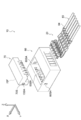
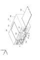
- the connector 10 of this embodiment includes a plurality (six) of terminals 20, a housing 60, and a retainer 70.
- the terminal 20 is accommodated in the housing 60, and then the retainer 70 is fitted into the housing 60 accommodating the terminal 20, whereby the connector 10 is assembled (see FIG. 2).
- the six terminals 20 have the same configuration. One of the six terminals 20 is shown in FIGS. Hereinafter, the terminal 20 will be described with reference to FIGS. 4 and 5.
- the arrow X shown in FIG. 4 and FIG. 5 is described as the terminal front direction, the arrow Y as one side in the terminal width direction (left direction), and the arrow Z as the terminal upward direction.
- front and rear, top and bottom, width (left and right) are used unless otherwise specified, front and rear in the front and rear direction of the terminal, vertical and vertical in the terminal vertical direction, and width (left and right) in the terminal width (left and right) direction are indicated.
- the front and rear, left and right, and up and down directions of the terminal 20 substantially coincide with the front and rear, left and right, and up and down directions of the connector 10.
- the terminal 20 is formed by, for example, bending after a plate material is punched.
- the material of the terminal 20 is a conductive material such as a copper alloy, for example.
- the terminal 20 has a proximal end portion 30 on one end side, a distal end portion 50 on the other end side, and a spring portion 40 positioned between the distal end portion 50 and the proximal end portion 30.
- the base end portion 30 has a U-shape or a C-shape in which both sides in the width direction are bent upward (in the thickness direction inner surface side) as a whole, and a cross-sectional shape perpendicular to the front-rear direction is opened upward. .
- the base end portion 30 extends forward from the rear end 20 ⁇ / b> B of the terminal 20.
- the base end part 30 has the electric wire connection part 31 and the base end side controlled part 32 in this order toward the other end side from the one end side.
- the electric wire connecting portion 31 is a portion connected to the electric wire 80 as the “flexible wiring material”, and corresponds to the “flexible wiring material connecting portion” of the present invention.
- the wire connection portion 31 includes a cover crimp portion 31A that is crimped to the sheath 84 of the electric wire 80 (see FIG. 1) and a core wire crimp portion 31B that is crimped to the core wire 82 (see FIG. 3) of the wire 80.
- the base end side restricted portion 32 is a portion for restricting the movement range of the base end portion 30 by contacting the housing 60 and the retainer 70.
- the proximal-side regulated portion 32 has a U shape in which a cross-sectional shape orthogonal to the terminal front-rear direction is opened upward. That is, the base-side regulated portion 32 includes a bottom plate portion 33 extending in the width direction, a right plate portion 34 extending upward from the right end portion of the bottom plate portion 33, and a left plate extending upward from the left end portion of the bottom plate portion 33. Part 34.
- the right side plate portion 34 and the left side plate portion 34 of the base end side restricted portion 32 may be collectively referred to as a pair of side plate portions 34 of the base end side restricted portion 32.
- the side plate part 34 has a front surface 34F facing forward, an upper surface 34U facing upward, and a rear surface 34R facing rearward. Further, a tapered surface 35 is formed between the front surface 34F and the upper surface 34U and faces forward and upward in an oblique direction.
- a lance 36 is formed on the bottom plate portion 33 of the base end side restricted portion 32.
- the lance 36 is formed by bending the center portion in the width direction of the bottom plate portion 33 downward (outer surface side in the plate thickness direction).
- the spring part 40 has the 1st linear part 41, the inclination part 42, the 1st curved part 43, the 2nd linear part 44, and the 2nd curved part 45 in this order toward the other end side from the one end side.
- the spring portion 40 has substantially the same width dimension from one end to the other end, and the width dimension is smaller than the width dimension of the proximal-side regulated portion 32, specifically, one third or less. It is said that.
- the first straight portion 41 extends forward from the central portion in the width direction of the bottom plate portion 33 in the base end side restricted portion 32.
- the first straight portion 41 has a plate thickness direction in the up-down direction, and extends linearly in the forward direction from one end to the other end.
- the extending direction of the first linear portion 41 is substantially parallel to the front-rear direction of the terminal.
- the other end side of the first linear portion 41 is connected to the inclined portion 42 through a bent portion that is slightly bent toward the inner surface side in the thickness direction.
- the inclined portion 42 has a plate thickness direction substantially in the vertical direction, and extends linearly in a direction slightly inclined upward (forward and diagonally forward) from one end to the other end with respect to the front direction. .
- the angle formed by the extending direction of the inclined portion 42 and the terminal front-rear direction is an angle of less than 45 degrees, and in the present embodiment, the angle is approximately 20 degrees.
- the other end side in the extending direction of the inclined portion 42 is connected to the first curved portion 43.
- the first curved portion 43 is bent toward the inner surface side in the thickness direction, and has a convexly curved shape.
- the first curved portion 43 changes the direction of extension from one end to the other end by approximately 160 degrees.
- the other end side in the extending direction of the first curved portion 43 is connected to the second linear portion 44.
- the second straight portion 44 has the plate thickness direction in the up-down direction, and extends linearly backward from one end to the other end.
- the extending direction of the second straight portion 44 is substantially parallel to the front-rear direction of the terminal.
- the other end side in the extending direction of the second linear portion 44 is connected to the second curved portion 45.
- the second curved portion 45 is bent toward the outer surface side in the thickness direction, and has a convex shape rearward. Specifically, the second curved portion 45 includes two bent portions 45C bent by approximately 90 degrees. The extending direction of the second curved portion 45 is changed by approximately 180 degrees from one end to the other end. The other end side in the extending direction of the second curved portion 45 is connected to the tip-side restricted portion 51 of the tip portion 50.
- the distal end portion 50 includes a distal end side restricted portion 51 and a contact portion 52.
- the tip side restricted portion 51 is a portion for limiting the movement range of the tip portion 50 by contacting the housing 60 and the retainer 70.
- the contact part 52 is a part that contacts the connection object 90.
- the front end side restricted portion 51 has a substantially rectangular cross-sectional shape in the front-rear direction.
- the tip side restricted portion 51 includes a lower plate portion 51B, a right plate portion 51R extending upward from the right end portion of the lower plate portion 51B, and an upper plate portion extending leftward from the upper end of the right plate portion 51R.
- 51T and the left board part 51L extended below from the left side edge part of the upper board part 51T.
- the spring part 40 is connected to the center part in the width direction at the rear end of the lower plate part 51B.
- the contact part 52 has a pair of contact piece parts 52A.
- Each of the pair of contact piece portions 52A extends forward from the center in the width direction at the front end of the upper plate portion 51T and the lower plate portion 51B of the tip side regulated portion 51 of the tip portion 50.
- the pair of contact piece portions 52 ⁇ / b> A are electrically connected to each other by contacting the connection object 90 in the vertical direction.
- the housing 60 is formed in a substantially rectangular parallelepiped shape by an insulator such as synthetic resin.
- the arrow X is the front direction of the housing
- the arrow Y is the one side in the housing width direction (left direction)
- the arrow Z is the upward direction of the housing.
- front and rear, top and bottom, width (left and right) are used, the front and rear in the front and rear direction of the housing, the top and bottom in the top and bottom direction of the housing, and the width (left and right) in the housing width (left and right) direction are used.
- the front / rear, left / right and up / down directions of the housing 60 coincide with the front / rear, left / right and up / down directions of the connector 10.
- the housing 60 has an accommodating portion 61 that accommodates the terminal 20.
- the accommodating portion 61 is a space formed in the housing 60 and extending in the front-rear direction, and is formed in plural (six in this embodiment corresponding to the number of terminals 20).
- the six accommodating portions 61 have the same configuration as each other, and are formed at equal intervals along the housing width direction.
- FIG. 6 is a cross-sectional view of the six storage portions 61 taken along a plane perpendicular to the lateral direction of the housing at the center in the width direction of the leftmost storage portion 61.
- the illustration of the terminal 20 corresponding to the leftmost accommodating part 61 is omitted, and the other accommodating part 61 shows a state where the terminal 20 is accommodated.
- a terminal push-in opening 61R is formed on the rear surface 60R of the housing 60, and the terminal push-in opening 61R is connected to the accommodating portion 61.
- the terminal 20 is accommodated in the accommodating portion 61 by pushing the terminal 20 into the accommodating portion 61 from the terminal insertion opening 61R. Specifically, as shown in FIG. 1, the terminal 20 is pushed forward from the terminal push-in opening 61 ⁇ / b> R on the rear surface 60 ⁇ / b> R of the housing 60 with the front / rear / left / right direction of the terminal 20 and the front / rear / left / right direction of the housing 60 aligned.
- the terminal 20 can be accommodated in the accommodating portion 61.
- a substantially rectangular retainer fitting opening 60 ⁇ / b> BH that opens upward in the housing is formed in the front-rear direction intermediate portion 60 ⁇ / b> B (housing intermediate portion 60 ⁇ / b> B) of the housing 60.
- the retainer fitting opening 60 ⁇ / b> BH is connected to the six accommodating portions 61. Therefore, the ceiling surface 61T of the accommodating part 61 does not exist in the housing middle part 60B.
- the plurality of accommodating portions 61 are separated from each other. That is, in the housing rear portion 60C, a pair of left and right side wall surfaces 61S is formed from the bottom surface 61B to the ceiling surface 61T for each housing portion 61. As illustrated in FIG. 3, the electric wire connection portion 31 and the electric wire 80 of the base end portion 30 of the terminal 20 are disposed between the pair of left and right side wall surfaces 61 ⁇ / b> S in the housing rear portion 60 ⁇ / b> C.
- the pair of left and right side wall surfaces 61S are formed lower than the side wall surface 61S of the housing rear portion 60C.
- the height of the side wall surface 61S of the housing middle portion 60B is lower than the ceiling surface 61T of the housing rear portion 60C.
- the side wall surface 61S of the housing intermediate portion 60B is interrupted at the intermediate position in the front-rear direction of the housing intermediate portion 60B. That is, when the housing intermediate portion 60B is further divided into the front side and the rear side, the side wall surface 61S is formed on the rear side of the housing intermediate portion 60B, but the side wall surface 61S is formed on the front side of the housing intermediate portion 60B.
- the base-side regulated portion 32 of the terminal 20 is disposed between the pair of left and right side wall surfaces 61S of the housing intermediate portion 60B (the accommodating portion 61 in the housing intermediate portion 60B).
- the plurality of accommodating parts 61 are separated from each other. That is, in the housing front portion 60A, a pair of left and right side wall surfaces 61S is formed from the bottom surface 61B to the ceiling surface 61T for each accommodating portion 61.
- the height of the ceiling surface 61T of the housing rear portion 60C and the ceiling surface 61T of the housing front portion 60A are the same. As shown in FIG.
- a tip 50 is arranged.
- the distance between the pair of left and right side wall surfaces 61S (the width dimension of the accommodating portion 61) is larger than the width dimension of the distal-side regulated portion 51 and the proximal-side regulated portion 32 of the terminal 20. Largely formed.
- the distal-side restricted portion 51 and the proximal-side restricted portion 32 can pass in the front-rear direction between the pair of left and right side wall surfaces 61S of the housing rear portion 60C. ing.
- the base-side regulated portion 32 can be disposed between the pair of left and right side wall surfaces 61S of the housing intermediate portion 60B in a state where the terminal 20 is accommodated in the accommodating portion 61.
- the distance between the pair of left and right side wall surfaces 61 ⁇ / b> S is formed to be smaller than the width dimension of the front end side restricted portion 51.
- a recess 62 that enlarges the distance between the pair of left and right side wall surfaces 61S is formed in a portion adjacent to the housing middle portion 60B in the housing front portion 60A and in the vicinity of the ceiling surface 61T.
- the recesses 62 are formed on both the pair of left and right side wall surfaces 61 ⁇ / b> S, and a pair of left and right sides are formed for each storage portion 61.
- the distance between the pair of left and right recesses 62 is formed to be equal to or larger than the width dimension of the tip side restricted portion 51 of the terminal 20. Further, the vertical dimension of the recess 62 is formed to be the same as or larger than the vertical dimension of the front end side restricted portion 51.
- the front-rear dimension of the recess 62 is formed to be the same as or larger than the front-rear dimension of the front end side restricted part 51. For this reason, in a state where the front end side restricted portion 51 is pushed forward into the concave portion 62, the front end side restricted portion 51 does not protrude into the housing intermediate portion 60B (the portion where the retainer fitting port 60BH is formed). It has become.
- the upper portion of the accommodating portion 61 in the housing front portion 60 ⁇ / b> A is the tip arrangement portion (the front housing portion) where the tip portion 50 of the terminal 20 is arranged.
- the upper portion of the accommodating portion 61 in the portion 60A) and the lower portion become a spring arrangement portion (a lower portion of the accommodating portion 61 in the housing front portion 60A) where a part of the spring portion 40 is arranged.
- the second curved portion 45 of the spring portion 40 is disposed in the accommodating portion 61 in the housing intermediate portion 60B.
- a terminal insertion port 61F is formed on the front side of the tip arrangement portion (the upper portion of the housing portion 61 in the housing front portion 60A).
- the terminal insertion port 61F passes through the front wall of the housing 60 that separates the outer space in front of the housing 60 and the accommodating portion 61 in the front-rear direction, and the cross-sectional shape orthogonal to the front-rear direction of the housing is rectangular. .
- On the front surface 60F side of the housing 60 of the terminal insertion port 61F a tapered portion 61FA is formed that gradually expands in the vertical and horizontal directions as it goes to the front side of the housing.
- the male terminal which is the connection target 90 is guided to the terminal insertion port 61F by the taper portion 61FA.
- the rearward movement range of the tip 50 is not limited by the housing 60.
- the proximal-side regulated portion 32 is disposed near the front end between the pair of left and right side wall surfaces 61S of the housing intermediate portion 60B. Then, in the vicinity of the front and upper end portions of the pair of left and right side wall surfaces 61S of the housing middle portion 60B, as a “contact portion” that reduces the distance between the pair of left and right side wall surfaces 61S (the width dimension of the housing portion 61).
- a protruding portion 63 is formed.
- the protrusion 63 has a substantially rectangular parallelepiped shape.
- the side plate portion 34 of the base end side restricted portion 32 of the terminal 20 is arranged directly below the protruding portion 63.
- the upper surface 34U of the right side plate portion 34 of the base end side restricted portion 32 comes into contact with the lower surface of the right protruding portion 63 and the base end side coverage is increased.
- the upper surface 34U of the left side plate portion 34 of the restricting portion 32 contacts the lower surface of the left protruding portion 63. That is, the range of movement of the proximal end portion 30 in the connector upward direction is limited by the protruding portion 63 (“contact portion”) which is a part of the housing 60.
- a lance locking hole 64 is formed in the bottom surface 61B of the accommodating portion 61 at a position where the proximal-side regulated portion 32 is disposed.
- the lance locking hole 64 is formed so as to penetrate the bottom surface 61 ⁇ / b> B, and locks the lance 36 of the base end portion 30 of the terminal 20.
- the retainer 70 will be described. After the terminal 20 is pushed into and accommodated in the accommodating portion 61 of the housing 60, the retainer 70 is fitted into the retainer fitting opening 60 ⁇ / b> BH of the housing 60. At this time, the locking portions 70SA formed on the left and right side surfaces 70S of the retainer 70 are locked to the locked portions 60SA of the housing 60 (see FIGS. 1 and 2).
- the arrow X shown in FIG. 7 will be described as the retainer forward direction, the arrow Y as the retainer width direction one side (left direction), and the arrow Z as the retainer upward direction.
- the terms front and rear, up and down, and width (left and right) are used unless otherwise specified, the front and rear in the front and rear direction of the retainer, the up and down in the retainer up and down direction, and the width (left and right) in the retainer width (left and right) direction are indicated.
- the front / rear, left / right and up / down directions of the retainer 70 substantially coincide with the front / rear, left / right and up / down directions of the connector 10.
- FIG. 7 is a cross-sectional view of the retainer 70 cut at a position corresponding to FIG.
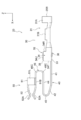
- the retainer 70 is formed with a plurality of spring portion disposition grooves 71 (six corresponding to the number of terminals 20) whose depth direction is the retainer upper direction.
- the spring portion arranging grooves 71 extend in the front-rear direction of the retainer, and are formed side by side at equal intervals in the retainer width direction.
- the pair of side wall surfaces 71S of the spring portion arranging groove 71 functions similarly to the pair of side wall surfaces 61S of the accommodating portion 61 in a state where the retainer 70 is fitted (see FIG. 3).
- the second curved portion 45 of the terminal 20 is disposed between the pair of side wall surfaces 71 ⁇ / b> S of the spring portion disposition groove 71 with the retainer 70 fitted. .
- the width dimension of the spring part arrangement groove 71 is larger than the width dimension of the spring part 40 of the terminal 20 and smaller than the width dimension of the distal-side regulated part 51 and the proximal-side regulated part 32. .
- the bottom surface 71B of the spring portion arranging groove 71 functions similarly to the ceiling surface 61T of the accommodating portion 61 in a state where the retainer 70 is fitted (see FIG. 3).
- the bottom surface 71B of the spring portion disposition groove 71 is lower than the ceiling surface 61T of the housing front portion 60A and lower than the ceiling surface of the housing rear portion 60C. Be placed.
- the front surface 70F of the retainer 70 is disposed behind the right plate portion 51R, the left plate portion 51L, and the upper plate portion 51T in the front end side restricted portion 51. Become.
- the retainer 70 has seven downward projecting portions 72 separated by six spring portion arrangement grooves 71.
- the front portion 70A (retainer front portion 70A) of the retainer 70 is disposed in a portion of the housing intermediate portion 60B where the side wall surface 61S is not formed. Therefore, the downward projecting portion 72A of the retainer front portion 70A is formed long downward.
- the lower end of the downward projecting portion 72 is in contact with or close to the bottom surface 61B of the accommodating portion 61 in the retainer front portion 70A.
- a tapered portion 73 whose width dimension and vertical dimension are gradually reduced is formed.
- the rear surface 72AR of the downward projecting portion 72A of the retainer front portion 70A is disposed in front of the pair of side plate portions 34 in the proximal-side regulated portion 32 of the terminal 20. Will be placed.
- the retainer rear portion 70B is disposed in a portion of the housing middle portion 60B where the side wall surface 61S is formed. Therefore, the downward projecting portion 72B of the retainer rear portion 70B is formed with a smaller downward projecting amount than the retainer front portion 70A.
- a base end rear restricting portion 74 protrudes further downward from a rear portion of the downward projecting portion 72B of the retainer rear portion 70B.
- the proximal rear end restricting portion 74 is disposed so as to protrude below the protruding portion 63 behind the protruding portion 63 of the housing 60.
- the rear end restricting portion 74 is disposed behind the pair of side plate portions 34 in the base end side restricted portion 32 of the terminal 20.
- the rear surfaces 34R of the pair of left and right side plate portions 34 of the base end-side restricted portion 32 are rear end-restricted. It contacts the part 74. That is, the range of movement of the proximal end portion 30 in the connector rearward direction is limited by the rear end restricting portion 74 of the retainer 70.
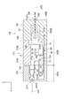
- the front-rear dimension L1 from the rear surface 72AR of the downward projection 72A of the retainer front part 70A to the rear-end rear restriction part 74 is larger than the front-rear dimension L2 of the proximal-side regulated part 32 of the terminal 20. Is formed large. Therefore, the base end portion 30 moves in a predetermined movement range (range L1-L2) in the connector front-rear direction with respect to the housing 60 and the retainer 70 in a state where the retainer 70 is fitted to the housing 60 (that is, an assembled state). It is possible. That is, when the electric wire 80 is pulled, the proximal-side regulated portion 32 moves to the rear of the connector as shown in FIG. On the other hand, when the electric wire 80 is pushed in, as shown in FIG. 10, the base end side restricted portion 32 moves forward of the connector.
- the connector 10 includes a terminal 20, a housing 60, and a retainer 70, and the retainer 70 is fitted into the housing 60 that accommodates the terminal 20.
- the terminal 20 has a proximal end portion 30 having a wire connection portion 31 connected to the electric wire 80 and a distal end portion 50 having a contact portion 52 in contact with the connection object 90. As shown in FIG. 3, the distal end portion 50 is prevented from being detached by a combination of the housing 60 and the retainer 70.
- the base end portion 30 is movable in the front-rear direction of the connector, which is the insertion / extraction direction of the connection object 90, with respect to the housing 60 and the retainer 70 in a state where the retainer 70 is fitted to the housing 60 (that is, an assembled state).
- the terminal 20 has a spring portion 40 located between the proximal end portion 30 and the distal end portion 50. For this reason, even if the electric wire 80 is bent so as to pull or push the terminal 20 in the longitudinal direction of the connector due to vibration or impact, the base end portion 30 having the electric wire connection portion 31 is connected to the housing 60 and the retainer 70.
- the base end portion 30 is movable within a predetermined movement range in the connector vertical direction in a state where the retainer 70 is fitted to the housing 60 (that is, an assembled state).
- the influence of the housing 60 and the retainer 70 due to this bending can be reduced.
- the spring portion 40 positioned between the distal end portion 50 and the proximal end portion 30 is not affected by this.
- the range in which the base end portion 30 moves in the vertical direction of the connector is limited within a predetermined range, the plastic deformation of the spring portion 40 is suppressed.
- the base end portion 30 is movable within a predetermined movement range in the left-right direction of the connector in a state where the retainer 70 is fitted to the housing 60 (that is, an assembled state). The For this reason, even if the electric wire 80 is bent so as to move the terminal 20 in the left-right direction of the connector, the influence of the housing 60 and the retainer 70 due to this bending can be reduced. As a result, it is possible to suppress the influence of this bending from reaching the distal end portion 50 via the housing 60 and the retainer 70.
- the spring portion 40 positioned between the distal end portion 50 and the proximal end portion 30 is not affected by this.
- the range in which the base end portion 30 moves in the left-right direction of the connector is limited within a predetermined range, the plastic deformation of the spring portion 40 is suppressed.
- the housing 60 has a tip placement portion (an upper portion of the housing portion 61 in the housing front portion 60A) in which the tip portion 50 of the terminal 20 can be placed, and this tip placement portion (housing front portion).
- the upper portion of the accommodating portion 61 in 60 ⁇ / b> A has a front-end restricting portion (a concave portion 62 of the housing 60) that restricts the movement range of the front-end portion 50 in the connector front direction.
- the retainer 70 has a rear end restricting portion (a front surface 70 ⁇ / b> F of the retainer 70) that restricts the range of movement of the front end portion 50 in the connector rearward direction in a state of being fitted to the housing 60.
- the terminal 20 when assembling the connector 10, the terminal 20 until the distal end portion 50 of the terminal 20 comes into contact with the front end restricting portion (the recessed portion 62 of the housing 60) of the distal end arrangement portion (the upper portion of the housing portion 61 in the housing front portion 60 ⁇ / b> A). Can be temporarily positioned with respect to the housing 60 by pushing in the connector forward direction. Thereafter, the retainer 70 is fitted into the housing 60, whereby the tip 50 of the terminal 20 can be prevented from coming off. Therefore, the connector 10 can be easily assembled.
- the front end restricting portion the recessed portion 62 of the housing 60
- the distal end arrangement portion the upper portion of the housing portion 61 in the housing front portion 60 ⁇ / b> A
- the housing 60 has a bottom portion (a bottom surface 61B of the housing portion 61) that restricts the range of movement of the base end portion 30 in the connector downward direction, which is the fitting direction of the retainer 70, and the fitting direction of the retainer 70.
- a protruding portion 63 as a “contact portion” that restricts the movement range of the base end portion 30 in the connector upward direction, which is the opposite direction.
- the base end portion 30 of the terminal 20 has a lance 36
- the housing 60 has a lance locking hole 64 for locking the lance 36.
- the lance 36 of the base end portion 30 is locked to the lance locking hole 64 of the housing 60 by pushing the terminal 20 into the housing portion 61 of the housing 60 in the forward direction of the connector.
- the range of movement of the base end portion 30 in the connector rearward direction is temporarily limited. Therefore, since the range of movement of the base end portion 30 in the connector rearward direction is limited in a state before the retainer 70 is fitted, the connector 10 can be easily assembled.
- a tapered surface 35 is formed on the base-end-side regulated portion 32 of the terminal 20.
- the retainer 70 has a base end front restricting portion (a rear surface 72AR of the downward projecting portion 72A of the retainer front portion 70A) that limits the movement range of the base end portion 30 in the connector front direction in the assembled state. Yes.
- the spring of the terminal 20 is pushed when the connector 10 is pushed into the accommodating portion 61 of the housing 60 as compared with the aspect in which the housing 60 has a portion that limits the movement range of the proximal end portion 30 in the connector front direction.
- the portion 40 or the like is not caught by the proximal end front restricting portion, and is easily pushed.
- shaft AX1 of the contact part 52 of the terminal 20 is wire connection axis
- shaft of a flexible wiring material connection part is wire connection axis
- shaft AX2 connection axis
- the spring portion 40 extending from the base end portion 30 to the tip end portion 50 includes: The first bent portion 43 and the second straight portion 44 as “folded portions” folded back in the connector rear direction are configured. For this reason, the easiness of deformation of the spring part 40 can be further ensured, and the sliding at the contact can be more effectively suppressed.
- the end portion (first curved portion 43) in the connector front direction of the “folded portion” is the housing portion 61 of the housing front portion 60A in front of the housing middle portion 60B to which the retainer 70 is fitted. Placed in. For this reason, since the full length of the spring part 40 can be set long, it is easy to ensure the ease of deformation of the spring part 40.
- the first bent portion 43 that is the end portion of the folded portion in the front direction of the connector is present on the front side of the connector with respect to the contact point P (see FIG. 3) in the contact portion 52 of the terminal 20. The movement of the base end 30 is very easily absorbed by the deformation of 40. Furthermore, in this embodiment, as shown in FIG.
- the end portion (second bent portion 45) of the “folded portion” of the terminal 20 in the connector rear direction is between the pair of side wall surfaces 71 ⁇ / b> S of the spring portion arranging groove 71. Placed in. That is, the end portion (second bent portion 45) of the “folded portion” of the terminal 20 in the connector rear direction is arranged in the housing portion 61 in the housing middle portion 60B. For this reason, since the full length of the spring part 40 can be set still longer, it is easy to ensure the ease of deformation
- the protruding portion 63 is formed on the housing 60, and the protruding portion 63 is the base end portion 30 in the counter-fitting direction (connector upward direction) that is opposite to the fitting direction of the retainer 70.
- the protruding portion 63 may not be formed on the housing 60, and a “contact portion” that restricts the range of movement of the proximal end portion 30 in the connector upward direction may be formed on the retainer 70.
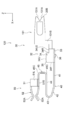
- the connector 110 has an object (“flexible wiring material”) connected to one end side (connector rear side) of the terminal 120 as an electric wire. It is different from the above-described embodiment in that it is FPC 180 (“flat wiring material”) instead of 80. In relation to this difference, the base end portion 30 and the like of the terminal 120 are different from the connector 10 according to the above-described embodiment. In other embodiments, unlike the above-described embodiments, the FPC 180 as a “flexible wiring material” and a “flat wiring material” can be inserted into and removed from the assembled connector 110 (FIG. 15). And FIG. 16).
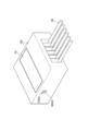
- the connector 110 includes a plurality (six) of terminals 120, a housing 160, a retainer 170, and a cover 190.
- the terminal 120 is accommodated in the housing 160 (see FIG. 13), and then the retainer 170 is fitted into the housing 160 that accommodates the terminal 120 (see FIG. 14) and the cover 190 is assembled, whereby the connector 110 is assembled. Assembled (see FIG. 15).
- the six terminals 120 have the same configuration. One of the six terminals 120 is shown in FIGS. Hereinafter, the terminal 120 will be described.
- the terminal 120 is formed by, for example, bending after a plate material is punched.
- the material of the terminal 120 is, for example, a conductive material such as a copper alloy.
- the terminal 120 has a proximal end portion 30 on one end side, a distal end portion 50 on the other end side, and a spring portion 40 positioned between the distal end portion 50 and the proximal end portion 30.
- the base end portion 30 extends forward from the rear end 20 ⁇ / b> B of the terminal 120.
- the base end portion 30 has an FPC connection portion 131 and a base end side restricted portion 32 in this order from one end side to the other end side.
- the FPC connection portion 131 is a portion connected to the FPC 180 as a “flexible wiring material” and corresponds to the “flexible wiring material connection portion” of the present invention.
- the FPC connecting portion 131 has a contact portion 131A that contacts the FPC 180 (see FIG. 18), and a displacement portion 131B that displaces the position contacting the FPC 180 to the middle side in the connector vertical direction from the proximal-side regulated portion 32. is doing.
- the FPC connection part 131 has its plate thickness direction in the connector width direction.
- the other end side (front end side) of the FPC connection portion 131 is connected to a right side plate portion 34 (one of the pair of side plate portions 34) of the base end side restricted portion 32 described later.
- the FPC connecting portion 131 and the right side plate portion 34 are located on the same plane.
- the contact portions 131A are formed as a pair and come into contact with the FPC 180 so as to be sandwiched from both sides.
- the proximal-side regulated portion 32 is a portion for restricting the movement range of the proximal end portion 30 by contacting the housing 160 and the retainer 170.
- the proximal-side regulated portion 32 has a U shape in which a cross-sectional shape orthogonal to the terminal front-rear direction is opened upward. That is, the base-side regulated portion 32 includes a bottom plate portion 33 extending in the width direction, a right plate portion 34 extending upward from the right end portion of the bottom plate portion 33, and a left plate extending upward from the left end portion of the bottom plate portion 33. Part 34.
- the right side plate portion 34 and the left side plate portion 34 of the base end side restricted portion 32 may be collectively referred to as a pair of side plate portions 34 of the base end side restricted portion 32.
- the side plate part 34 has a front surface 34F facing forward, an upper surface 34U facing upward, and a rear surface 34R facing rearward. Further, a tapered surface 35 is formed between the front surface 34F and the upper surface 34U and faces forward and upward in an oblique direction. Further, the side plate portion 34 has a second upper surface 34U2 facing upward. The second upper surface 34U2 is formed so as to be connected to the lower end of the rear surface 34R, and is positioned below and behind the upper surface 34U.
- a lance 36 is formed on the bottom plate portion 33 of the base end side restricted portion 32.
- the lance 36 is formed by bending the center portion in the width direction of the bottom plate portion 33 downward (outer surface side in the plate thickness direction).
- the spring part 40 has the 1st linear part 41, the inclination part 42, the 1st curved part 43, the 2nd linear part 44, and the 2nd curved part 45 in this order toward the other end side from the one end side. Since the spring part 40 has the same structure as the spring part 40 of the terminal 20 in the above-described embodiment, the description thereof is omitted.
- the distal end portion 50 includes a distal end side restricted portion 51 and a contact portion 52.
- the tip side restricted portion 51 is a portion for restricting the movement range of the tip portion 50 by contacting the housing 160 and the retainer 170. Since the tip portion 50 has the same structure as the spring portion 50 of the terminal 20 in the above-described embodiment, the description thereof is omitted.
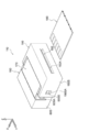
- the housing 160 is formed in a substantially rectangular parallelepiped shape by an insulator such as synthetic resin.
- the housing 160 has an accommodating portion 161 that accommodates the terminal 120.
- a plurality of accommodating portions 161 are formed (six in this embodiment corresponding to the number of terminals 120).
- the six accommodating portions 161 have the same configuration as each other, and are formed at equal intervals along the housing width direction.
- the terminal 120 can be accommodated in the accommodating portion 161 by pushing the terminal 120 forward from the rear of the housing 160.
- the housing 160 has a rear portion 160B (housing rear portion 160B, see FIG. 19) formed with a substantially rectangular retainer fitting port 160BH that opens upward from the housing.
- the retainer insertion opening 160BH is connected to the six accommodating portions 61. Therefore, in the housing rear portion 160B, the ceiling surface 61T (see FIG. 19) of the accommodating portion 161 does not exist.
- the pair of left and right side wall surfaces 61S are formed lower than the left and right side walls 60S of the housing 160. Further, the side wall surface 61S of the housing rear portion 160B is interrupted at an intermediate position in the front-rear direction of the housing rear portion 160B. That is, when the housing rear portion 160B is further divided into the front side and the rear side, the side wall surface 61S is formed on the rear side of the housing rear portion 160B, but the side wall surface 61S is not formed on the front side of the housing rear portion 160B. As shown in FIG.
- the base-side regulated portion 32 of the terminal 120 is disposed between the pair of left and right side wall surfaces 61S of the housing rear portion 160B (the accommodating portion 161 in the housing rear portion 160B).
- a displacement portion 131B of the FPC connection portion 131 of the terminal 120 is disposed in the housing portion 61 in the housing rear portion 160B.
- the plurality of accommodating portions 161 are separated from each other. That is, as shown in FIG. 19, in the housing front portion 160A, a pair of left and right side wall surfaces 61S is formed from the bottom surface 61B to the ceiling surface 61T for each accommodating portion 161. As shown in FIGS. 18 and 19, a part of the spring portion 40 of the terminal 120 (for example, the first curved portion) is interposed between the pair of left and right side wall surfaces 61S in the housing front portion 160A (the accommodating portion 61 in the housing front portion 60A). 43) and the tip 50 are arranged.
- the distance between the pair of left and right side wall surfaces 61 ⁇ / b> S is formed to be smaller than the width dimension of the front end side restricted portion 51.
- a recess 62 is formed in the front part 60A of the housing adjacent to the housing middle part 60B and in the vicinity of the ceiling surface 61T to increase the distance between the pair of left and right side wall surfaces 61S. Yes.
- the recesses 62 are formed on both the pair of left and right side wall surfaces 61 ⁇ / b> S, and a pair of left and right sides are formed for each storage portion 61.
- the distance between the pair of left and right recesses 62 is formed to be equal to or larger than the width dimension of the tip-side restricted portion 51 of the terminal 120. Further, the vertical dimension of the recess 62 is formed to be the same as or larger than the vertical dimension of the front end side restricted portion 51.
- the front-rear dimension of the recess 62 is formed to be the same as or larger than the front-rear dimension of the front end side restricted part 51. For this reason, in a state where the front end side restricted portion 51 is pushed forward into the concave portion 62, the front end side restricted portion 51 does not protrude into the housing intermediate portion 60B (the portion where the retainer fitting port 60BH is formed). It has become.
- the upper portion of the accommodating portion 61 in the housing front portion 160 ⁇ / b> A is the tip arrangement portion (the housing front portion) where the tip portion 50 of the terminal 120 is arranged.
- the upper portion of the accommodating portion 161 in the portion 160A) and the lower portion become a spring arrangement portion (a lower portion of the accommodating portion 161 in the housing front portion 160A) in which a part of the spring portion 40 is disposed.
- the second bent portion 45 of the spring portion 40 is disposed in the accommodating portion 161 in the housing rear portion 160B.
- a terminal insertion port 61F is formed on the front side of the tip arrangement portion (the upper portion of the housing portion 161 in the housing front portion 160A).
- the terminal insertion port 61F passes through the front wall of the housing 160 that separates the external space in front of the housing 160 and the accommodating portion 161 in the front-rear direction, and the cross-sectional shape orthogonal to the front-rear direction of the housing is rectangular.
- a tapered portion 61FA is formed that gradually expands in the vertical and horizontal directions toward the front side of the housing.
- the rearward movement range of the tip 50 is not limited by the housing 160.
- the proximal-side regulated portion 32 is disposed near the front end between the pair of left and right side wall surfaces 61S of the housing rear portion 160B. Note that the pair of left and right side wall surfaces 61S of the housing rear portion 160B is not formed with a protruding portion 63 (see FIG. 6) as a “contact portion”.
- the range of movement of the base end 30 in the connector upward direction is not limited.
- a lance locking hole 64 is formed at a position of the bottom surface 61B of the accommodating portion 161 where the proximal-side regulated portion 32 is disposed.
- the lance locking hole 64 is formed so as to penetrate the bottom surface 61 ⁇ / b> B, and locks the lance 36 of the base end portion 30 of the terminal 120.
- the retainer 170 is formed with a plurality (six corresponding to the number of terminals 120) of spring portion arranging grooves 171 whose depth direction is the retainer upper direction.
- the spring portion arranging grooves 171 respectively extend in the front-rear direction of the retainer, and are formed at equal intervals in the retainer width direction.
- the pair of side wall surfaces 71S of the spring portion arranging groove 171 functions similarly to the pair of side wall surfaces 61S of the accommodating portion 161 in a state where the retainer 170 is fitted (see FIG. 19).
- the second curved portion 45 of the terminal 120 is disposed between the pair of side wall surfaces 71 ⁇ / b> S of the spring portion disposition groove 171 with the retainer 170 fitted. .
- the width dimension of the spring part arrangement groove 171 is larger than the width dimension of the spring part 40 of the terminal 120 and smaller than the width dimension of the distal-side regulated part 51 and the proximal-side regulated part 32. .
- the bottom surface 71B of the spring portion arranging groove 171 functions similar to the ceiling surface 61T of the accommodating portion 161 in a state where the retainer 170 is fitted (see FIG. 19). As shown in FIG. 19, in a state where the retainer 170 is fitted, the bottom surface 71B of the spring portion disposition groove 171 is disposed at a position lower than the ceiling surface 61T of the housing front portion 60A.
- the front surface 70F of the retainer 170 is disposed behind the right plate portion 51R, the left plate portion 51L, and the upper plate portion 51T in the distal-side regulated portion 51.
- the retainer 170 has seven downward projecting portions 172 separated by six spring portion arrangement grooves 171.
- the front portion 170A (retainer front portion 170A) of the retainer 170 is disposed in a portion of the housing rear portion 160B where the side wall surface 61S is not formed. Therefore, the downward protrusion 72A of the retainer front portion 170A is formed long downward.
- the lower end of the downward projecting portion 72 is in contact with or close to the bottom surface 61B of the accommodating portion 161 in the retainer front portion 170A.
- a tapered portion 73 whose width dimension and vertical dimension are gradually reduced is formed.
- the retainer rear portion 170B is disposed in a portion of the housing rear portion 160B where the side wall surface 61S is formed. Therefore, the downward projecting portion 72B of the retainer rear portion 170B is formed with a smaller downward projecting amount than the retainer front portion 170A.
- a base end rear restricting portion 74 is further projected downward.
- the rear end restricting portion 74 is disposed behind the pair of side plate portions 34 in the base end side restricted portion 32 of the terminal 120.
- proximal-side rear regulating portion 74 is disposed above the second upper surface 34U2 of the pair of side plate portions 34 in the proximal-side regulated portion 32 of the terminal 120.
- the second upper surfaces 34U2 of the pair of left and right side plate portions 34 of the proximal end side restricted portion 32 are proximal ends. It contacts the rear restricting portion 74 from below. That is, the range of movement of the proximal end portion 30 in the connector upward direction is limited by the rear end restricting portion 74 of the retainer 170. That is, in the present embodiment, the rear end restricting portion 74 of the retainer 170 functions as a “contact portion” that restricts the movement range of the proximal end portion 30 in the counter-fitting direction of the retainer 170. That is, in this embodiment, not the housing 160 but the retainer 170 has the “contact portion”. Of course, in the present embodiment, a protrusion 63 (see FIG. 3 and the like) as a “contact portion” may be formed on the housing 160.
- the base end portion 30 is movable within a predetermined movement range in the connector front-rear direction with respect to the housing 160 and the retainer 170 in a state where the retainer 170 is fitted to the housing 160.
- ⁇ Cover 190> Next, the cover 190 will be described. As shown in FIGS. 14 and 15, a cover 190 is attached to the housing 160 from the rear side. At this time, the locked portions 190SA formed on the left and right side walls 190S of the cover 190 are locked to the protruding locking portions 60SB formed on the left and right side walls 60S of the housing 160.
- the upper surface 190U, the lower surface 190B, the left and right side surfaces 190S, and the rear surface 190R of the cover 190 constitute the outer surface of the connector 110 at the rear part of the connector 110 in the assembled state, as shown in FIGS.
- the upper surface 190U and the lower surface 190B of the cover 190 are substantially flush with the upper and lower surfaces of the housing 160 and the retainer 170.
- the left and right side surfaces 190S of the cover 190 have a step with respect to the left and right side walls 60S of the housing 160.
- the cover 190 has a flat wiring material insertion hole 192 into which the FPC 180 is inserted.
- a taper 192A for guiding the FPC 180 is formed vertically and horizontally.
- the cover 190 has a terminal accommodating portion 193 that accommodates the FPC connecting portions 131 of the plurality of terminals 120.
- the terminal accommodating part 193 is open toward the front.
- the cover 190 has a plurality (five) of partition walls 194 that separate the FPC connection portions 131 of the plurality (six) of terminals 120 from each other.
- the partition wall 194 is formed with a flat wiring material arrangement groove 194A for arranging the FPC 180.
- the connector 110 includes a terminal 120, a housing 160, and a retainer 170, and the retainer 170 is fitted into the housing 160 that accommodates the terminal 120.
- the terminal 120 has a proximal end portion 30 having an FPC connection portion 131 that is connected to the FPC 180, and a distal end portion 50 having a contact portion 52 that is in contact with the connection object 90. As shown in FIG. 18, the distal end portion 50 is prevented from being detached by a combination of the housing 160 and the retainer 170.
- the base end portion 30 is movable in the connector front-rear direction, which is the insertion / extraction direction of the connection object 90, with respect to the housing 160 and the retainer 170 in a state where the retainer 170 is fitted to the housing 160 (that is, an assembled state).
- the terminal 120 has a spring portion 40 located between the proximal end portion 30 and the distal end portion 50. For this reason, even if the FPC 180 is bent so as to pull or push the terminal 120 in the longitudinal direction of the connector due to vibration or impact, the proximal end portion 30 having the FCP connection portion 131 is not connected to the housing 160 and the retainer 170 in the longitudinal direction of the connector.
- the spring portion 40 is suppressed from being plastically deformed.
- Connector 20 Terminal 30 Base End 31 Electric Wire Connection (Flexible Wiring Material Connection) 40 Spring part 43 First curved part (turned part) 44 Second straight part (turned part) 50 Front end portion 52 Contact portion 60 Housing 60BH Retainer fitting port 61 Housing portion 61B Bottom surface (bottom portion) of housing portion 62 Concave part (front end restricting part) 63 Protruding part (contact part) 70 Front of retainer 70F (rear end restriction part) The rear surface of the downward projecting part of the 72AR retainer front part (base end front restricting part) 74 Rear end restricting portion 80 Electric wire (wiring material having flexibility) 90 Connection object AX1 Insertion / extraction axis AX2 Electric wire connection axis (connection axis of flexible wiring material connection part) 110 Connector 120 Terminal 131 FPC connection part (flexible wiring material connection part) 160 Housing 170 Retainer 180 FPC (wiring material having flexibility) 190 Cover
Abstract
This connector 10 is provided with: a terminal 20 connected in an electrically conductive manner to an object 90 to be connected, which is inserted and extracted; a housing 60 for containing the terminal 20; and a retainer 70 fitted to the housing 60 having the terminal 20 contained therein. The terminal 20 has: a base end section 30 having an electric wire connection section 31 (flexible wiring material connection section) connecting to an electric wire 80 (flexible wiring material); a front end section 50 having a contact section 52 coming into contact with the object 90 to be connected; and a spring section 40 located between the base end section 30 and the front end section 50. The base end section 30 is movable in a predetermined movable range in the front and rear direction of the connector while the retainer 70 is fitted to the housing 60, the front and rear direction being the direction in which the object 90 to be connected is inserted into and extracted from the housing 60.
Description
本発明は、コネクタに関する。
The present invention relates to a connector.
従来、自動車等の内部配線の接続には、特許文献1に記載されているようなコネクタが用いられている。
Conventionally, a connector as described in Patent Document 1 is used for connection of internal wiring of an automobile or the like.
特許文献1に記載のコネクタは、ハウジングと、このハウジングに収容されると共に一端(端子部)で接続対象物と接続して他端(バレル部)で電線と圧着接続する圧着端子と、ハウジングに嵌着されるリテーナと、を備えている。ハウジングにリテーナが嵌着されることで、電線に接続された圧着端子がハウジング内に抜け止めされる。
このようなコネクタでは、当該コネクタと接続対象物との接続作業時に電線の可撓性を活かしてコネクタを比較的自由に取り回しできるため、作業性が良い。 The connector described in Patent Literature 1 is housed in a housing, a crimp terminal that is accommodated in the housing, is connected to an object to be connected at one end (terminal portion), and is crimp-connected to an electric wire at the other end (barrel portion). And a retainer to be fitted. When the retainer is fitted into the housing, the crimp terminal connected to the electric wire is prevented from coming off in the housing.
In such a connector, workability is good because the connector can be handled relatively freely by utilizing the flexibility of the electric wire during the connection work between the connector and the connection object.
しかしながら、上述のようなコネクタでは、接続対象物と接続した状態で振動や衝撃によって電線が撓むと、ハウジングに収容された圧着端子が電線に引っ張られたり押し込まれたりすることがある。すると、圧着端子における一端(端子部)における接続対象物との接点部で摺動が起こってしまうおそれがある。
However, in the connector as described above, when the electric wire bends due to vibration or impact while connected to the connection target, the crimp terminal accommodated in the housing may be pulled or pushed into the electric wire. Then, there exists a possibility that sliding may occur in the contact part with the connection target in one end (terminal part) in the crimp terminal.
また、上述のようなコネクタにおいて、端子の他端に接続される対象を電線ではなく、FPC(Flexible printed circuits、フレキシブルプリント回路基板、フレキシブルプリント配線板)やFFC(Flexible Flat Cable、フレキシブルフラットケーブル)にすることが考えられる(つまり、FPC接続用コネクタ、FFC接続用コネクタとすることが考えられる)。FPCやFFCも電線と同じく可撓性を有するため、撓むことがあり、その場合、電線である場合と同様に撓みの影響が端子に伝わって接点摺動が起こるおそれがある。
In addition, in the connector as described above, the target to be connected to the other end of the terminal is not an electric wire, but FPC (Flexible printed circuits, flexible printed circuit board, flexible printed wiring board) or FFC (Flexible フ レ キ シ ブ ル Flat Cable, flexible flat cable) (That is, an FPC connector and an FFC connector may be considered). Since FPC and FFC have the same flexibility as electric wires, they may be bent, and in that case, the influence of the bending may be transmitted to the terminals as in the case of electric wires, and contact sliding may occur.
本発明は、以上のような問題点に鑑みてなされたものであり、その目的は、振動や衝撃によって可撓性を有する配線材(電線やFPC、FFCなど)が撓んだ場合の接点での摺動を抑制することができるコネクタを提供することにある。
The present invention has been made in view of the above problems, and its purpose is a contact when a flexible wiring material (electric wire, FPC, FFC, etc.) is bent by vibration or impact. It is an object of the present invention to provide a connector capable of suppressing the sliding.
第一の態様に係るコネクタは、挿抜される接続対象物に導通接続する端子と、前記端子を収容するハウジングと、前記端子を収容した前記ハウジングに嵌着するリテーナと、を備えるコネクタであって、前記端子は、可撓性を有する配線材と接続する可撓性配線材接続部を有する基端部と、前記接続対象物と接触する接触部を有する先端部と、前記基端部と前記先端部との間に位置するバネ部と、を有しており、前記先端部は、前記ハウジングと前記リテーナとの組合せにより、又は、前記ハウジングにより抜け止めされ、前記リテーナが前記ハウジングに嵌着した状態において、前記基端部は、所定の可動域で前記ハウジングに対して前記接続対象物の挿抜方向であるコネクタ前後方向に移動可能とされる。
A connector according to a first aspect is a connector comprising: a terminal that is conductively connected to a connection object to be inserted / extracted; a housing that houses the terminal; and a retainer that fits into the housing that houses the terminal. The terminal includes a base end portion having a flexible wiring material connecting portion connected to a flexible wiring material, a tip end portion having a contact portion in contact with the connection object, the base end portion, and the base end portion. A spring portion positioned between the distal end portion and the distal end portion is prevented from coming off by a combination of the housing and the retainer or by the housing, and the retainer is fitted into the housing. In this state, the base end portion is movable in the longitudinal direction of the connector, which is the insertion / extraction direction of the connection object, with respect to the housing within a predetermined movable range.
第一の態様に係るコネクタでは、コネクタが、端子とハウジングとリテーナとを備える。端子を収容したハウジングにリテーナが嵌着するようになっている。端子は、接続対象物と接触する接触部を有する先端部を有しており、先端部は、上述のハウジングとリテーナとの組合せで抜け止めされるか、又は、(例えば、ハウジングに圧入されることで)ハウジングにより抜け止めされる。
In the connector according to the first aspect, the connector includes a terminal, a housing, and a retainer. A retainer is fitted into the housing that houses the terminal. The terminal has a distal end portion having a contact portion that comes into contact with the connection object, and the distal end portion is prevented from being detached by a combination of the above-described housing and retainer, or (for example, press-fitted into the housing). It is prevented from coming off by the housing.
ここで、基端部は、ハウジングに対して接続対象物の挿抜方向であるコネクタ前後方向に移動可能である。そして、端子は、基端部と先端部との間に位置するバネ部を有している。
このため、振動や衝撃などにより、可撓性を有する配線材(電線やFPC、FFCなど)が端子をコネクタ前後方向に引っ張ったり押し込んだりするように撓んでも、可撓性配線材接続部を有する基端部がハウジングに対してコネクタ前後方向に移動することで、この撓みからハウジングが影響を受けることを抑制することができる。その結果、撓みの影響がハウジングを介して先端部に及ぶことを抑制することができる。
またこのため、振動や衝撃などにより、可撓性を有する配線材が端子をコネクタ前後方向に引っ張ったり押し込んだりするように撓んでも、先端部と基端部との間に位置するバネ部がこの撓みに応じて変形することで、この撓みから接触部を有する先端部が影響を受けることを抑制することができる。
これらの作用により、接触部と接続対象物との接点での摺動が抑制される。 Here, the base end portion is movable in the connector front-rear direction, which is the insertion / extraction direction of the connection object with respect to the housing. And the terminal has a spring part located between a base end part and a front-end | tip part.
Therefore, even if a flexible wiring material (such as an electric wire, FPC, or FFC) is bent by pulling or pushing the terminal in the front-rear direction of the connector due to vibration or impact, the flexible wiring material connecting portion The proximal end portion having the movement in the connector front-rear direction with respect to the housing can suppress the housing from being affected by this bending. As a result, it is possible to suppress the influence of the deflection from reaching the tip portion through the housing.
For this reason, even if the flexible wiring material is bent by pulling or pushing the terminal in the front-rear direction of the connector due to vibration or impact, the spring portion positioned between the distal end portion and the proximal end portion is not provided. By deform | transforming according to this bending, it can suppress that the front-end | tip part which has a contact part is influenced from this bending.
By these actions, sliding at the contact point between the contact portion and the connection object is suppressed.
さらに、ハウジングに対する基端部のコネクタ前後方向の移動は、所定の可動域に制限されている。このため、バネ部が塑性変形してしまうことが抑制される。
Furthermore, the movement of the base end portion in the longitudinal direction of the connector relative to the housing is limited to a predetermined movable range. For this reason, it is suppressed that a spring part deforms plastically.
第二の態様に係るコネクタは、第一の態様に係るコネクタにおいて、前記ハウジングは、前記先端部を配置可能な先端配置部を有しており、前記先端配置部は、前記接続対象物の抜去方向であるコネクタ前方向の前記先端部の移動範囲を制限する先端前規制部を有しており、前記リテーナは、前記ハウジングに嵌着した状態において前記接続対象物の挿入方向であるコネクタ後方向の前記先端部の移動範囲を制限する先端後規制部を有している。
The connector according to a second aspect is the connector according to the first aspect, wherein the housing has a tip placement portion on which the tip portion can be placed, and the tip placement portion removes the connection object. A connector front-restricting portion that restricts a range of movement of the tip portion in the connector front direction, which is the direction of the connector, and the retainer is a connector rear direction in which the connection object is inserted in a state of being fitted to the housing And a rear end restricting portion for restricting the movement range of the front end portion.
第二の態様に係るコネクタでは、ハウジングが、先端部を配置可能な先端配置部を有しており、この先端配置部は、先端部のコネクタ前方向の移動範囲を制限する先端前規制部を有している。また、リテーナが、ハウジングに嵌着した状態において先端部のコネクタ後方向の移動範囲を制限する先端後規制部を有している。
このため、端子をハウジングに収容する際に、端子の先端部が先端配置部の先端前規制部に当接するまで端子を押し込むことで、端子のハウジングに対する仮位置決めを行うことができる。そして、その後にリテーナをハウジングに嵌着させることで、端子の先端部が抜け止めされる。したがって、容易に組み立てることができる。 In the connector according to the second aspect, the housing has a tip placement portion on which the tip portion can be placed, and the tip placement portion has a tip front restricting portion that limits a movement range of the tip portion in the connector front direction. Have. Further, the retainer has a rear end restricting portion that restricts a range of movement of the front end portion in the rear direction of the connector in a state where the retainer is fitted to the housing.
For this reason, when the terminal is accommodated in the housing, the terminal can be temporarily positioned with respect to the housing by pushing the terminal until the distal end portion of the terminal comes into contact with the front end restricting portion of the distal end arrangement portion. Then, by attaching the retainer to the housing thereafter, the tip of the terminal is prevented from coming off. Therefore, it can be assembled easily.
第三の態様に係るコネクタは、第一又は第二の態様に係るコネクタにおいて、前記ハウジングは、前記リテーナの嵌着方向の前記基端部の移動を規制する底部と、前記リテーナの嵌着方向とは反対方向である反嵌着方向の前記基端部の移動範囲を規制する当接部と、を有している。
The connector according to a third aspect is the connector according to the first or second aspect, wherein the housing includes a bottom portion that restricts movement of the base end portion in the fitting direction of the retainer, and a fitting direction of the retainer. And an abutting portion that regulates the movement range of the base end portion in the counter-fitting direction that is the opposite direction.
第三の態様に係るコネクタでは、ハウジングが、リテーナの嵌着方向の基端部の移動を規制する底部と、リテーナの嵌着方向とは反対方向である反嵌着方向の基端部の移動範囲を規制する当接部と、を有している。このため、端子をハウジングに収容した後であってリテーナをハウジングに嵌着していない状態において、基端部が嵌着方向又は反嵌着方向に大きく動いてしまうことが防止されている。したがって、組み立てやすいコネクタとすることができる。
In the connector according to the third aspect, the housing has a bottom portion that restricts movement of the proximal end portion of the retainer in the fitting direction, and a movement of the proximal end portion in the opposite fitting direction that is opposite to the fitting direction of the retainer. A contact portion for regulating the range. For this reason, after the terminal is accommodated in the housing and in a state where the retainer is not fitted to the housing, the base end portion is prevented from moving greatly in the fitting direction or the counter-fitting direction. Therefore, the connector can be easily assembled.
第四の態様に係るコネクタは、第三の態様に係るコネクタにおいて、前記基端部と前記底部及び前記当接部との間には、前記基端部の前記リテーナの嵌着反嵌着方向であるコネクタ上下方向の移動を許容する可動間隙が存在し、前記リテーナが前記ハウジングに嵌着した状態において、前記基端部は、コネクタ上下方向に所定の移動範囲で移動可能である。
The connector according to a fourth aspect is the connector according to the third aspect, wherein the retainer of the base end portion is fitted and counterfitted between the base end portion, the bottom portion, and the contact portion. There is a movable gap that allows the connector to move in the vertical direction, and the base end portion is movable in a predetermined movement range in the connector vertical direction in a state where the retainer is fitted to the housing.
第四の態様に係るコネクタでは、基端部と底部及び当接部との間には、基端部のコネクタ上下方向の移動を許容する可動間隙が存在し、リテーナがハウジングに嵌着した状態において、基端部は、コネクタ上下方向に所定の移動範囲で移動可能である。
このため、可撓性を有する配線材が、端子をコネクタ上下方向に移動させるように撓んでも、この撓みからハウジングやリテーナが受ける影響を低減することができる。その結果、この撓みの影響がハウジングやリテーナを介して先端部に及ぶことを抑制することができる。
またこのため、振動や衝撃などにより、可撓性を有する配線材が端子をコネクタ上下方向に引っ張ったり押し込んだりするように撓んでも、先端部と基端部との間に位置するバネ部がこの撓みに応じて変形することで、この撓みから接触部を有する先端部が受ける影響を低減することができる。
さらに、基端部がコネクタ上下方向に移動する範囲は、所定の範囲で制限されているため、バネ部が塑性変形することが抑制される。 In the connector according to the fourth aspect, there is a movable gap that allows the base end portion to move in the vertical direction of the connector between the base end portion, the bottom portion, and the contact portion, and the retainer is fitted to the housing. The base end portion is movable in a predetermined movement range in the vertical direction of the connector.
For this reason, even if the flexible wiring material is bent so as to move the terminal in the vertical direction of the connector, it is possible to reduce the influence of the housing and the retainer due to this bending. As a result, it is possible to suppress the influence of this bending from reaching the tip portion via the housing and the retainer.
For this reason, even if the flexible wiring material is bent by pulling or pushing the terminal in the vertical direction of the connector due to vibration or impact, the spring portion positioned between the distal end portion and the proximal end portion is not provided. By deforming according to this bending, the influence which the front-end | tip part which has a contact part receives from this bending can be reduced.
Furthermore, since the range in which the base end portion moves in the vertical direction of the connector is restricted within a predetermined range, the plastic deformation of the spring portion is suppressed.
第五の態様に係るコネクタは、第一~第四の何れかの態様に係るコネクタにおいて、前記基端部は、前記接続対象物の挿入方向と前記リテーナの嵌着方向の両方に垂直な方向であるコネクタ幅方向において、前記ハウジングに対して隙間を空けた状態で収容されており、前記リテーナが前記ハウジングに嵌着した状態において、前記基端部が前記隙間の範囲で前記コネクタ幅方向の移動が可能である。
The connector according to a fifth aspect is the connector according to any one of the first to fourth aspects, wherein the base end portion is a direction perpendicular to both the insertion direction of the connection object and the fitting direction of the retainer. In the connector width direction, the housing is accommodated in a state where there is a gap with respect to the housing, and in a state where the retainer is fitted to the housing, the base end portion is in the range of the gap in the connector width direction. It is possible to move.
第五の態様に係るコネクタでは、基端部が、接続対象物の挿入方向とリテーナの嵌着方向の両方に垂直な方向であるコネクタ幅方向において、ハウジングに対して隙間を空けた状態で収容されており、リテーナがハウジングに嵌着した状態において、基端部が隙間の範囲でコネクタ幅方向の移動が可能である。つまり、リテーナがハウジングに嵌着した状態において、コネクタ左右方向の所定の移動範囲で移動可能とされる。
このため、可撓性を有する配線材が、端子をコネクタ左右方向に移動させるように撓んでも、この撓みからハウジングやリテーナが受ける影響を低減することができる。その結果、この撓みの影響がハウジングやリテーナを介して先端部に及ぶことを抑制することができる。
またこのため、振動や衝撃などにより、可撓性を有する配線材が端子をコネクタ左右方向に引っ張ったり押し込んだりするように撓んでも、先端部と基端部との間に位置するバネ部がこの撓みに応じて変形することで、この撓みから接触部を有する先端部が受ける影響を低減することができる。
さらに、基端部がコネクタ左右方向に移動する範囲は、所定の範囲で制限されているため、バネ部が塑性変形することが抑制される。 In the connector according to the fifth aspect, the base end portion is accommodated in a state where there is a gap with respect to the housing in the connector width direction which is a direction perpendicular to both the insertion direction of the connection object and the fitting direction of the retainer. In the state where the retainer is fitted to the housing, the base end portion can move in the connector width direction within the gap. That is, in a state where the retainer is fitted to the housing, the retainer can move within a predetermined movement range in the left-right direction of the connector.
For this reason, even if the flexible wiring material is bent so as to move the terminal in the left-right direction of the connector, it is possible to reduce the influence of the housing and the retainer from this bending. As a result, it is possible to suppress the influence of this bending from reaching the tip portion via the housing and the retainer.
For this reason, even if the flexible wiring material is bent by pulling or pushing the terminal in the left-right direction of the connector due to vibration or impact, the spring portion positioned between the distal end portion and the proximal end portion is not provided. By deforming according to this bending, the influence which the front-end | tip part which has a contact part receives from this bending can be reduced.
Furthermore, since the range in which the base end portion moves in the left-right direction of the connector is limited within a predetermined range, the plastic deformation of the spring portion is suppressed.
第六の態様に係るコネクタは、第一~第五の何れかの態様に係るコネクタにおいて、前記接触部の挿抜軸は、前記可撓性配線材接続部の接続軸と略平行で、かつ、前記リテーナの嵌着方向の位置がずれている。
The connector according to a sixth aspect is the connector according to any one of the first to fifth aspects, wherein the insertion / extraction shaft of the contact portion is substantially parallel to the connection axis of the flexible wiring member connection portion, and The position of the retainer in the fitting direction is shifted.
第六の態様に係るコネクタでは、接触部の挿抜軸は、可撓性配線材接続部の接続軸と略平行で、かつ、リテーナの嵌着方向の位置がずれているため、コネクタの前後方向の寸法の拡大を抑制しつつバネ部の変形のしやすさを確保することができ、もって接点での摺動を効果的に抑制することができる。
In the connector according to the sixth aspect, the insertion / extraction shaft of the contact portion is substantially parallel to the connection shaft of the flexible wiring member connection portion, and the position of the retainer in the fitting direction is displaced, so the front-rear direction of the connector The ease of deformation of the spring portion can be ensured while suppressing the increase in the size of the spring, and the sliding at the contact can be effectively suppressed.
第七の態様に係るコネクタは、第六の態様に係るコネクタにおいて、前記バネ部は、前記接続対象物の挿入方向であるコネクタ後方向へ折り返された折返し部を含んで構成されている。
The connector according to a seventh aspect is the connector according to the sixth aspect, wherein the spring portion includes a folded portion that is folded back in the connector rear direction, which is the insertion direction of the connection object.
第七の態様に係るコネクタでは、挿抜軸と可撓性配線材接続部の接続軸とがコネクタ上下方向の位置がずれて配置されていることに加えて、基端部から先端部へと延びるバネ部が、コネクタ後方向へ折り返された折返し部を含んで構成されている。このため、バネ部の変形しやすさをより一層確保することができ、もって接点での摺動を効果的により一層抑制することができる。
In the connector according to the seventh aspect, in addition to the insertion / extraction shaft and the connection shaft of the flexible wiring member connection portion being arranged with the position in the connector vertical direction being shifted, the connector extends from the proximal end portion to the distal end portion. The spring portion includes a folded portion that is folded back in the connector rear direction. For this reason, the ease of deformation of the spring portion can be further ensured, and the sliding at the contact can be more effectively suppressed.
以上説明したように、本発明は、振動や衝撃によって電線が撓んだ場合の接点での摺動を抑制することができるという優れた効果を有する。
As described above, the present invention has an excellent effect that it is possible to suppress sliding at the contact when the electric wire is bent due to vibration or impact.
以下、本発明の一実施形態に係るコネクタ10について説明する。
Hereinafter, the connector 10 according to an embodiment of the present invention will be described.
<コネクタ>
図1に示すように、本実施形態のコネクタ10は、複数(6つ)の端子20と、ハウジング60と、リテーナ70と、を備えている。まず、端子20がハウジング60に収容され、その後、端子20を収容したハウジング60にリテーナ70が嵌着されることで、コネクタ10が組み立てられる(図2参照)。 <Connector>
As shown in FIG. 1, theconnector 10 of this embodiment includes a plurality (six) of terminals 20, a housing 60, and a retainer 70. First, the terminal 20 is accommodated in the housing 60, and then the retainer 70 is fitted into the housing 60 accommodating the terminal 20, whereby the connector 10 is assembled (see FIG. 2).
図1に示すように、本実施形態のコネクタ10は、複数(6つ)の端子20と、ハウジング60と、リテーナ70と、を備えている。まず、端子20がハウジング60に収容され、その後、端子20を収容したハウジング60にリテーナ70が嵌着されることで、コネクタ10が組み立てられる(図2参照)。 <Connector>
As shown in FIG. 1, the
<端子>
6つの端子20は、互いに同一の構成とされている。6つの端子20のうちの1つを図4及び図5に示す。以下、端子20について図4及び図5を用いて説明する。 <Terminal>
The sixterminals 20 have the same configuration. One of the six terminals 20 is shown in FIGS. Hereinafter, the terminal 20 will be described with reference to FIGS. 4 and 5.
6つの端子20は、互いに同一の構成とされている。6つの端子20のうちの1つを図4及び図5に示す。以下、端子20について図4及び図5を用いて説明する。 <Terminal>
The six
以下の端子20についての説明では、図4及び図5に示される矢印Xを端子前方向、矢印Yを端子幅方向一方側(左方向)、矢印Zを端子上方向として説明する。また、特記なく前後、上下、幅(左右)という語を用いる場合は、端子前後方向の前後、端子上下方向の上下、端子幅(左右)方向の幅(左右)を示すものとする。なお、組み立てられた状態において、端子20の前後、左右、上下方向は、コネクタ10の前後、左右、上下方向と略一致する。
In the following description of the terminal 20, the arrow X shown in FIG. 4 and FIG. 5 is described as the terminal front direction, the arrow Y as one side in the terminal width direction (left direction), and the arrow Z as the terminal upward direction. In addition, when the terms front and rear, top and bottom, width (left and right) are used unless otherwise specified, front and rear in the front and rear direction of the terminal, vertical and vertical in the terminal vertical direction, and width (left and right) in the terminal width (left and right) direction are indicated. In the assembled state, the front and rear, left and right, and up and down directions of the terminal 20 substantially coincide with the front and rear, left and right, and up and down directions of the connector 10.
端子20は、例えば、板材が打ち抜き加工された後、曲げ加工されることで形成されている。端子20の材質は、例えば、銅合金などの導電性を有する材質である。
The terminal 20 is formed by, for example, bending after a plate material is punched. The material of the terminal 20 is a conductive material such as a copper alloy, for example.
端子20は、その一端側の基端部30と、その他端側の先端部50と、先端部50と基端部30との間に位置するバネ部40と、を有している。
The terminal 20 has a proximal end portion 30 on one end side, a distal end portion 50 on the other end side, and a spring portion 40 positioned between the distal end portion 50 and the proximal end portion 30.
(基端部30)
基端部30は、全体として幅方向両側が上方(板厚方向内面側)へ曲げられており、前後方向に直交する断面形状が上方に開放されたU字状またはC字状とされている。基端部30は、端子20の後端20Bから前方へ向けて延びている。基端部30は、その一端側から他端側へ向けて、電線接続部31と基端側被規制部32とをこの順に有している。 (Base end 30)
Thebase end portion 30 has a U-shape or a C-shape in which both sides in the width direction are bent upward (in the thickness direction inner surface side) as a whole, and a cross-sectional shape perpendicular to the front-rear direction is opened upward. . The base end portion 30 extends forward from the rear end 20 </ b> B of the terminal 20. The base end part 30 has the electric wire connection part 31 and the base end side controlled part 32 in this order toward the other end side from the one end side.
基端部30は、全体として幅方向両側が上方(板厚方向内面側)へ曲げられており、前後方向に直交する断面形状が上方に開放されたU字状またはC字状とされている。基端部30は、端子20の後端20Bから前方へ向けて延びている。基端部30は、その一端側から他端側へ向けて、電線接続部31と基端側被規制部32とをこの順に有している。 (Base end 30)
The
(電線接続部31)
電線接続部31は、「可撓性を有する配線材」としての電線80と接続する部分であり、本発明の「可撓性配線材接続部」に相当する。電線接続部31は、電線80(図1参照)の被覆84に圧着する被覆圧着部31Aと、電線80の芯線82(図3参照)に圧着する芯線圧着部31Bとを有している。 (Wire connection part 31)
The electricwire connecting portion 31 is a portion connected to the electric wire 80 as the “flexible wiring material”, and corresponds to the “flexible wiring material connecting portion” of the present invention. The wire connection portion 31 includes a cover crimp portion 31A that is crimped to the sheath 84 of the electric wire 80 (see FIG. 1) and a core wire crimp portion 31B that is crimped to the core wire 82 (see FIG. 3) of the wire 80.
電線接続部31は、「可撓性を有する配線材」としての電線80と接続する部分であり、本発明の「可撓性配線材接続部」に相当する。電線接続部31は、電線80(図1参照)の被覆84に圧着する被覆圧着部31Aと、電線80の芯線82(図3参照)に圧着する芯線圧着部31Bとを有している。 (Wire connection part 31)
The electric
(基端側被規制部32)
基端側被規制部32は、ハウジング60やリテーナ70に当接することで基端部30の移動範囲を制限するための部分である。基端側被規制部32は、端子前後方向に直交する断面形状が上方に開放されたU字状とされている。すなわち、基端側被規制部32は、幅方向に延びる底板部33と、底板部33の右側端部から上方へ延びる右側板部34と、底板部33の左側端部から上方へ延びる左側板部34と、を有している。以下、基端側被規制部32の右側板部34と左側板部34とを併せて、基端側被規制部32の一対の側板部34ということがある。 (Base end side restricted portion 32)
The base end side restrictedportion 32 is a portion for restricting the movement range of the base end portion 30 by contacting the housing 60 and the retainer 70. The proximal-side regulated portion 32 has a U shape in which a cross-sectional shape orthogonal to the terminal front-rear direction is opened upward. That is, the base-side regulated portion 32 includes a bottom plate portion 33 extending in the width direction, a right plate portion 34 extending upward from the right end portion of the bottom plate portion 33, and a left plate extending upward from the left end portion of the bottom plate portion 33. Part 34. Hereinafter, the right side plate portion 34 and the left side plate portion 34 of the base end side restricted portion 32 may be collectively referred to as a pair of side plate portions 34 of the base end side restricted portion 32.
基端側被規制部32は、ハウジング60やリテーナ70に当接することで基端部30の移動範囲を制限するための部分である。基端側被規制部32は、端子前後方向に直交する断面形状が上方に開放されたU字状とされている。すなわち、基端側被規制部32は、幅方向に延びる底板部33と、底板部33の右側端部から上方へ延びる右側板部34と、底板部33の左側端部から上方へ延びる左側板部34と、を有している。以下、基端側被規制部32の右側板部34と左側板部34とを併せて、基端側被規制部32の一対の側板部34ということがある。 (Base end side restricted portion 32)
The base end side restricted
側板部34は、前方を向いた前面34Fと、上方を向いた上面34Uと、後方を向いた後面34Rと、を有している。また、前面34Fと上面34Uとの間には、前方かつ上方の斜め方向を向いたテーパ面35が形成されている。
The side plate part 34 has a front surface 34F facing forward, an upper surface 34U facing upward, and a rear surface 34R facing rearward. Further, a tapered surface 35 is formed between the front surface 34F and the upper surface 34U and faces forward and upward in an oblique direction.
図5に示すように、基端側被規制部32の底板部33には、ランス36が形成されている。ランス36は、底板部33の幅方向中央部分が下方(板厚方向外面側)へ曲げられることで形成されている。
As shown in FIG. 5, a lance 36 is formed on the bottom plate portion 33 of the base end side restricted portion 32. The lance 36 is formed by bending the center portion in the width direction of the bottom plate portion 33 downward (outer surface side in the plate thickness direction).
(バネ部40)
バネ部40は、一端側から他端側へ向けて、第一直線部41、傾斜部42、第一曲部43、第二直線部44及び第二曲部45をこの順に有している。バネ部40はその一端から他端まで略同一の幅寸法とされており、その幅寸法は、基端側被規制部32の幅寸法よりも小さく、具体的には3分の1以下の寸法とされている。 (Spring part 40)
Thespring part 40 has the 1st linear part 41, the inclination part 42, the 1st curved part 43, the 2nd linear part 44, and the 2nd curved part 45 in this order toward the other end side from the one end side. The spring portion 40 has substantially the same width dimension from one end to the other end, and the width dimension is smaller than the width dimension of the proximal-side regulated portion 32, specifically, one third or less. It is said that.
バネ部40は、一端側から他端側へ向けて、第一直線部41、傾斜部42、第一曲部43、第二直線部44及び第二曲部45をこの順に有している。バネ部40はその一端から他端まで略同一の幅寸法とされており、その幅寸法は、基端側被規制部32の幅寸法よりも小さく、具体的には3分の1以下の寸法とされている。 (Spring part 40)
The
第一直線部41は、基端側被規制部32における底板部33の幅方向中央部分から前方へ延出されている。第一直線部41は、板厚方向を上下方向に向けており、一端から他端へ向けて前方向へ直線状に延びている。第一直線部41の延在方向は、端子前後方向と略平行とされている。第一直線部41の他端側は、板厚方向内面側へ若干屈曲された屈曲部を介して、傾斜部42に繋がっている。
The first straight portion 41 extends forward from the central portion in the width direction of the bottom plate portion 33 in the base end side restricted portion 32. The first straight portion 41 has a plate thickness direction in the up-down direction, and extends linearly in the forward direction from one end to the other end. The extending direction of the first linear portion 41 is substantially parallel to the front-rear direction of the terminal. The other end side of the first linear portion 41 is connected to the inclined portion 42 through a bent portion that is slightly bent toward the inner surface side in the thickness direction.
傾斜部42は、板厚方向を略上下方向に向けており、一端から他端へ向けて前方向に対して若干上方へ傾いた方向(前方かつ上方の斜め方向)に直線状に延びている。傾斜部42の延在方向と端子前後方向との成す角度は、45度未満の角度とされ、本実施形態では略20度の角度とされている。傾斜部42の延在方向他端側は、第一曲部43に繋がっている。
The inclined portion 42 has a plate thickness direction substantially in the vertical direction, and extends linearly in a direction slightly inclined upward (forward and diagonally forward) from one end to the other end with respect to the front direction. . The angle formed by the extending direction of the inclined portion 42 and the terminal front-rear direction is an angle of less than 45 degrees, and in the present embodiment, the angle is approximately 20 degrees. The other end side in the extending direction of the inclined portion 42 is connected to the first curved portion 43.
第一曲部43は、板厚方向内面側に曲げられており、前方へ凸の湾曲した形状となっている。第一曲部43は、その一端から他端までで延在方向を略160度方向転換している。第一曲部43の延在方向他端側は、第二直線部44に繋がっている。
The first curved portion 43 is bent toward the inner surface side in the thickness direction, and has a convexly curved shape. The first curved portion 43 changes the direction of extension from one end to the other end by approximately 160 degrees. The other end side in the extending direction of the first curved portion 43 is connected to the second linear portion 44.
第二直線部44は、板厚方向を上下方向に向けており、一端から他端へ向けて後方へ直線状に延びている。第二直線部44の延在方向は、端子前後方向と略平行とされている。第二直線部44の延在方向他端側は、第二曲部45に繋がっている。
The second straight portion 44 has the plate thickness direction in the up-down direction, and extends linearly backward from one end to the other end. The extending direction of the second straight portion 44 is substantially parallel to the front-rear direction of the terminal. The other end side in the extending direction of the second linear portion 44 is connected to the second curved portion 45.
第二曲部45は、板厚方向外面側に曲げられており、後方へ凸の形状となっている。具体的には、第二曲部45は、略90度曲げられた屈曲部45Cを2つ含んで構成されている。第二曲部45は、その一端から他端までで延在方向を略180度方向転換している。第二曲部45の延在方向他端側は、先端部50の先端側被規制部51に繋がっている。
The second curved portion 45 is bent toward the outer surface side in the thickness direction, and has a convex shape rearward. Specifically, the second curved portion 45 includes two bent portions 45C bent by approximately 90 degrees. The extending direction of the second curved portion 45 is changed by approximately 180 degrees from one end to the other end. The other end side in the extending direction of the second curved portion 45 is connected to the tip-side restricted portion 51 of the tip portion 50.
(先端部50)
先端部50は、先端側被規制部51と、接触部52と、を有している。先端側被規制部51は、ハウジング60やリテーナ70に当接することで先端部50の移動範囲を制限するための部分である。接触部52は、接続対象物90と接触する部分である。 (Tip 50)
Thedistal end portion 50 includes a distal end side restricted portion 51 and a contact portion 52. The tip side restricted portion 51 is a portion for limiting the movement range of the tip portion 50 by contacting the housing 60 and the retainer 70. The contact part 52 is a part that contacts the connection object 90.
先端部50は、先端側被規制部51と、接触部52と、を有している。先端側被規制部51は、ハウジング60やリテーナ70に当接することで先端部50の移動範囲を制限するための部分である。接触部52は、接続対象物90と接触する部分である。 (Tip 50)
The
先端側被規制部51は、前後方向に直交する断面形状が略矩形状とされている。具体的には、先端側被規制部51は、下板部51Bと、下板部51Bの右側端部から上方へ延びる右板部51Rと、右板部51Rの上端から左側へ延びる上板部51Tと、上板部51Tの左側端部から下方へ延びる左板部51Lと、から構成されている。このうち、下板部51Bの後端における幅方向中央部分にバネ部40が繋がっている。
The front end side restricted portion 51 has a substantially rectangular cross-sectional shape in the front-rear direction. Specifically, the tip side restricted portion 51 includes a lower plate portion 51B, a right plate portion 51R extending upward from the right end portion of the lower plate portion 51B, and an upper plate portion extending leftward from the upper end of the right plate portion 51R. 51T and the left board part 51L extended below from the left side edge part of the upper board part 51T. Among these, the spring part 40 is connected to the center part in the width direction at the rear end of the lower plate part 51B.
接触部52は、一対の接触片部52Aを有している。一対の接触片部52Aは、それぞれ、先端部50の先端側被規制部51の上板部51T及び下板部51Bの前端における幅方向中央から前方へ向けて延出されている。一対の接触片部52Aが接続対象物90に対して上下方向から接触することで導通接続するようになっている。
The contact part 52 has a pair of contact piece parts 52A. Each of the pair of contact piece portions 52A extends forward from the center in the width direction at the front end of the upper plate portion 51T and the lower plate portion 51B of the tip side regulated portion 51 of the tip portion 50. The pair of contact piece portions 52 </ b> A are electrically connected to each other by contacting the connection object 90 in the vertical direction.
<ハウジング60>
次に、ハウジング60について図1及び図6を用いて説明する。ハウジング60は、合成樹脂などの絶縁体によって略直方体形状に形成されている。 <Housing 60>
Next, thehousing 60 will be described with reference to FIGS. 1 and 6. The housing 60 is formed in a substantially rectangular parallelepiped shape by an insulator such as synthetic resin.
次に、ハウジング60について図1及び図6を用いて説明する。ハウジング60は、合成樹脂などの絶縁体によって略直方体形状に形成されている。 <
Next, the
以下のハウジング60についての説明では、矢印Xをハウジング前方向、矢印Yをハウジング幅方向一方側(左方向)、矢印Zをハウジング上方向として説明する。また、特記なく前後、上下、幅(左右)という語を用いる場合は、ハウジング前後方向の前後、ハウジング上下方向の上下、ハウジング幅(左右)方向の幅(左右)を示すものとする。なお、ハウジング60の前後、左右、上下方向は、コネクタ10の前後、左右、上下方向と一致する。
In the following description of the housing 60, the arrow X is the front direction of the housing, the arrow Y is the one side in the housing width direction (left direction), and the arrow Z is the upward direction of the housing. In addition, when the terms front and rear, top and bottom, width (left and right) are used, the front and rear in the front and rear direction of the housing, the top and bottom in the top and bottom direction of the housing, and the width (left and right) in the housing width (left and right) direction are used. The front / rear, left / right and up / down directions of the housing 60 coincide with the front / rear, left / right and up / down directions of the connector 10.
(収容部61)
ハウジング60は、端子20を収容する収容部61を有する。収容部61は、ハウジング60内に形成された前後方向に延びる空間とされており、複数(端子20の数に対応して本実施形態では6つ)形成されている。6つの収容部61は、互いに同様の構成とされ、ハウジング幅方向に並んで等間隔に形成されている。 (Accommodating part 61)
Thehousing 60 has an accommodating portion 61 that accommodates the terminal 20. The accommodating portion 61 is a space formed in the housing 60 and extending in the front-rear direction, and is formed in plural (six in this embodiment corresponding to the number of terminals 20). The six accommodating portions 61 have the same configuration as each other, and are formed at equal intervals along the housing width direction.
ハウジング60は、端子20を収容する収容部61を有する。収容部61は、ハウジング60内に形成された前後方向に延びる空間とされており、複数(端子20の数に対応して本実施形態では6つ)形成されている。6つの収容部61は、互いに同様の構成とされ、ハウジング幅方向に並んで等間隔に形成されている。 (Accommodating part 61)
The
図6は、6つの収容部61のうち最も左側の収容部61の幅方向中央で、ハウジング左右方向に垂直な平面で切断したときの断面図である。最も左側の収容部61に対応する端子20の図示は省略し、その他の収容部61には端子20が収容された状態を示している。
FIG. 6 is a cross-sectional view of the six storage portions 61 taken along a plane perpendicular to the lateral direction of the housing at the center in the width direction of the leftmost storage portion 61. The illustration of the terminal 20 corresponding to the leftmost accommodating part 61 is omitted, and the other accommodating part 61 shows a state where the terminal 20 is accommodated.
ハウジング60の後面60Rには端子押込口61Rが形成されており、端子押込口61Rは収容部61に繋がっている。この端子押込口61Rから端子20を収容部61に押し込むことで、端子20が収容部61に収容される。具体的には、図1に示すように端子20の前後左右方向とハウジング60の前後左右方向を一致させた状態で、ハウジング60の後面60Rの端子押込口61Rから端子20を前方に押し込むことで、端子20を収容部61に収容できるようになっている。
A terminal push-in opening 61R is formed on the rear surface 60R of the housing 60, and the terminal push-in opening 61R is connected to the accommodating portion 61. The terminal 20 is accommodated in the accommodating portion 61 by pushing the terminal 20 into the accommodating portion 61 from the terminal insertion opening 61R. Specifically, as shown in FIG. 1, the terminal 20 is pushed forward from the terminal push-in opening 61 </ b> R on the rear surface 60 </ b> R of the housing 60 with the front / rear / left / right direction of the terminal 20 and the front / rear / left / right direction of the housing 60 aligned. The terminal 20 can be accommodated in the accommodating portion 61.
図6に示すように、ハウジング60の前後方向中間部60B(ハウジング中間部60B)には、ハウジング上方へ開口する略矩形状のリテーナ嵌着口60BHが形成されている。リテーナ嵌着口60BHは6つの収容部61と繋がっている。そのため、ハウジング中間部60Bでは、収容部61の天井面61Tが存在しない。
As shown in FIG. 6, a substantially rectangular retainer fitting opening 60 </ b> BH that opens upward in the housing is formed in the front-rear direction intermediate portion 60 </ b> B (housing intermediate portion 60 </ b> B) of the housing 60. The retainer fitting opening 60 </ b> BH is connected to the six accommodating portions 61. Therefore, the ceiling surface 61T of the accommodating part 61 does not exist in the housing middle part 60B.
(ハウジング後部、左右一対の側壁面)
ハウジング60の後部60C(ハウジング後部60C)では、複数の収容部61が互いに分離されている。すなわち、ハウジング後部60Cでは、各々の収容部61につき、左右一対の側壁面61Sが底面61Bから天井面61Tにまで形成されている。
図3に示すように、ハウジング後部60Cにおける左右一対の側壁面61Sの間には、端子20の基端部30の電線接続部31と電線80が配置される。 (Housing rear, pair of left and right side walls)
In therear portion 60C (housing rear portion 60C) of the housing 60, the plurality of accommodating portions 61 are separated from each other. That is, in the housing rear portion 60C, a pair of left and right side wall surfaces 61S is formed from the bottom surface 61B to the ceiling surface 61T for each housing portion 61.
As illustrated in FIG. 3, the electricwire connection portion 31 and the electric wire 80 of the base end portion 30 of the terminal 20 are disposed between the pair of left and right side wall surfaces 61 </ b> S in the housing rear portion 60 </ b> C.
ハウジング60の後部60C(ハウジング後部60C)では、複数の収容部61が互いに分離されている。すなわち、ハウジング後部60Cでは、各々の収容部61につき、左右一対の側壁面61Sが底面61Bから天井面61Tにまで形成されている。
図3に示すように、ハウジング後部60Cにおける左右一対の側壁面61Sの間には、端子20の基端部30の電線接続部31と電線80が配置される。 (Housing rear, pair of left and right side walls)
In the
As illustrated in FIG. 3, the electric
ハウジング中間部60Bでは、左右一対の側壁面61Sが、ハウジング後部60Cの側壁面61Sよりも低く形成されている。ハウジング中間部60Bの側壁面61Sの高さは、ハウジング後部60Cの天井面61Tよりも低い位置となっている。
また、ハウジング中間部60Bの側壁面61Sは、ハウジング中間部60Bの前後方向中間位置で途切れている。すなわち、ハウジング中間部60Bをさらに前側と後側で分けた場合、ハウジング中間部60Bの後側には側壁面61Sが形成されているが、ハウジング中間部60Bの前側には側壁面61Sが形成されていない。
図3に示すように、ハウジング中間部60Bの左右一対の側壁面61Sの間(ハウジング中間部60Bにおける収容部61)には、端子20の基端側被規制部32が配置される。 In the housingmiddle portion 60B, the pair of left and right side wall surfaces 61S are formed lower than the side wall surface 61S of the housing rear portion 60C. The height of the side wall surface 61S of the housing middle portion 60B is lower than the ceiling surface 61T of the housing rear portion 60C.
Further, theside wall surface 61S of the housing intermediate portion 60B is interrupted at the intermediate position in the front-rear direction of the housing intermediate portion 60B. That is, when the housing intermediate portion 60B is further divided into the front side and the rear side, the side wall surface 61S is formed on the rear side of the housing intermediate portion 60B, but the side wall surface 61S is formed on the front side of the housing intermediate portion 60B. Not.
As shown in FIG. 3, the base-sideregulated portion 32 of the terminal 20 is disposed between the pair of left and right side wall surfaces 61S of the housing intermediate portion 60B (the accommodating portion 61 in the housing intermediate portion 60B).
また、ハウジング中間部60Bの側壁面61Sは、ハウジング中間部60Bの前後方向中間位置で途切れている。すなわち、ハウジング中間部60Bをさらに前側と後側で分けた場合、ハウジング中間部60Bの後側には側壁面61Sが形成されているが、ハウジング中間部60Bの前側には側壁面61Sが形成されていない。
図3に示すように、ハウジング中間部60Bの左右一対の側壁面61Sの間(ハウジング中間部60Bにおける収容部61)には、端子20の基端側被規制部32が配置される。 In the housing
Further, the
As shown in FIG. 3, the base-side
ハウジング60の前部60A(ハウジング前部60A)では、複数の収容部61が互いに分離されている。すなわち、ハウジング前部60Aでは、各々の収容部61につき、左右一対の側壁面61Sが底面61Bから天井面61Tにまで形成されている。ハウジング後部60Cの天井面61Tとハウジング前部60Aの天井面61Tの高さは同一である。
図3に示すように、ハウジング前部60Aにおける左右一対の側壁面61Sの間(ハウジング前部60Aにおける収容部61)に、端子20のバネ部40の一部(例えば第一曲部43)と先端部50とが配置される。 In thefront part 60 </ b> A (housing front part 60 </ b> A) of the housing 60, the plurality of accommodating parts 61 are separated from each other. That is, in the housing front portion 60A, a pair of left and right side wall surfaces 61S is formed from the bottom surface 61B to the ceiling surface 61T for each accommodating portion 61. The height of the ceiling surface 61T of the housing rear portion 60C and the ceiling surface 61T of the housing front portion 60A are the same.
As shown in FIG. 3, between the pair of left and right side wall surfaces 61S in thehousing front portion 60A (the housing portion 61 in the housing front portion 60A), a part of the spring portion 40 of the terminal 20 (for example, the first curved portion 43) A tip 50 is arranged.
図3に示すように、ハウジング前部60Aにおける左右一対の側壁面61Sの間(ハウジング前部60Aにおける収容部61)に、端子20のバネ部40の一部(例えば第一曲部43)と先端部50とが配置される。 In the
As shown in FIG. 3, between the pair of left and right side wall surfaces 61S in the
ハウジング後部60C及びハウジング中間部60Bでは、左右一対の側壁面61Sの間隔(収容部61の幅寸法)は、端子20の先端側被規制部51及び基端側被規制部32の幅寸法よりも大きく形成されている。これにより、端子20を収容部61内に押し込む際、ハウジング後部60Cの左右一対の側壁面61Sの間を、先端側被規制部51や基端側被規制部32が前後方向に通過可能となっている。またこれにより、端子20が収容部61に収容された状態で、ハウジング中間部60Bの左右一対の側壁面61Sの間に、基端側被規制部32が配置可能になっている。
In the housing rear portion 60C and the housing intermediate portion 60B, the distance between the pair of left and right side wall surfaces 61S (the width dimension of the accommodating portion 61) is larger than the width dimension of the distal-side regulated portion 51 and the proximal-side regulated portion 32 of the terminal 20. Largely formed. Thus, when the terminal 20 is pushed into the accommodating portion 61, the distal-side restricted portion 51 and the proximal-side restricted portion 32 can pass in the front-rear direction between the pair of left and right side wall surfaces 61S of the housing rear portion 60C. ing. Thereby, the base-side regulated portion 32 can be disposed between the pair of left and right side wall surfaces 61S of the housing intermediate portion 60B in a state where the terminal 20 is accommodated in the accommodating portion 61.
他方、ハウジング前部60Aでは、左右一対の側壁面61Sの間隔は、先端側被規制部51の幅寸法よりも小さく形成されている。
しかし、ハウジング前部60Aのうちハウジング中間部60Bと隣接する部分であって天井面61T付近には、左右一対の側壁面61Sの間隔を拡大する凹部62が形成されている。凹部62は、左右一対の側壁面61Sの両方に形成されており、各収容部61につき左右一対形成されている。
左右一対の凹部62の間隔は、端子20の先端側被規制部51の幅寸法と同一か大きく形成されている。また、凹部62の上下寸法は、先端側被規制部51の上下寸法と同一か大きく形成されている。 On the other hand, in thehousing front portion 60 </ b> A, the distance between the pair of left and right side wall surfaces 61 </ b> S is formed to be smaller than the width dimension of the front end side restricted portion 51.
However, arecess 62 that enlarges the distance between the pair of left and right side wall surfaces 61S is formed in a portion adjacent to the housing middle portion 60B in the housing front portion 60A and in the vicinity of the ceiling surface 61T. The recesses 62 are formed on both the pair of left and right side wall surfaces 61 </ b> S, and a pair of left and right sides are formed for each storage portion 61.
The distance between the pair of left andright recesses 62 is formed to be equal to or larger than the width dimension of the tip side restricted portion 51 of the terminal 20. Further, the vertical dimension of the recess 62 is formed to be the same as or larger than the vertical dimension of the front end side restricted portion 51.
しかし、ハウジング前部60Aのうちハウジング中間部60Bと隣接する部分であって天井面61T付近には、左右一対の側壁面61Sの間隔を拡大する凹部62が形成されている。凹部62は、左右一対の側壁面61Sの両方に形成されており、各収容部61につき左右一対形成されている。
左右一対の凹部62の間隔は、端子20の先端側被規制部51の幅寸法と同一か大きく形成されている。また、凹部62の上下寸法は、先端側被規制部51の上下寸法と同一か大きく形成されている。 On the other hand, in the
However, a
The distance between the pair of left and
また、凹部62の前後寸法は、先端側被規制部51の前後寸法と同一か大きく形成されている。このため、凹部62に先端側被規制部51が前方向に押し込まれた状態で、先端側被規制部51がハウジング中間部60B(リテーナ嵌着口60BHが形成された部分)に突出しないようになっている。
Further, the front-rear dimension of the recess 62 is formed to be the same as or larger than the front-rear dimension of the front end side restricted part 51. For this reason, in a state where the front end side restricted portion 51 is pushed forward into the concave portion 62, the front end side restricted portion 51 does not protrude into the housing intermediate portion 60B (the portion where the retainer fitting port 60BH is formed). It has become.
図3に示すように、端子20が収容部61に収容された状態では、ハウジング前部60Aにおける収容部61のうち、上部が、端子20の先端部50が配置される先端配置部(ハウジング前部60Aにおける収容部61の上部)となり、下部が、バネ部40の一部が配置されるバネ配置部(ハウジング前部60Aにおける収容部61の下部)となる。この状態では、ハウジング中間部60Bにおける収容部61にバネ部40の第二曲部45が配置される。
As shown in FIG. 3, in the state in which the terminal 20 is accommodated in the accommodating portion 61, the upper portion of the accommodating portion 61 in the housing front portion 60 </ b> A is the tip arrangement portion (the front housing portion) where the tip portion 50 of the terminal 20 is arranged. The upper portion of the accommodating portion 61 in the portion 60A) and the lower portion become a spring arrangement portion (a lower portion of the accommodating portion 61 in the housing front portion 60A) where a part of the spring portion 40 is arranged. In this state, the second curved portion 45 of the spring portion 40 is disposed in the accommodating portion 61 in the housing intermediate portion 60B.
先端配置部(ハウジング前部60Aにおける収容部61の上部)の前方側に端子差込口61Fが形成されている。端子差込口61Fは、ハウジング60の前方の外部空間と収容部61とを隔てるハウジング60の前壁を前後方向に貫通しており、ハウジング前後方向に直交する断面形状が矩形状とされている。端子差込口61Fの、ハウジング60の前面60F側には、ハウジング前方側へ向かうに従い、上下左右に次第に広がるテーパ部61FAが形成されている。テーパ部61FAにより接続対象物90であるオス端子が端子差込口61Fに誘導されるようになっている。端子差込口61Fに接続対象物90であるオス端子が差し込まれることで、端子20と接続対象物90とが導通接続する。
A terminal insertion port 61F is formed on the front side of the tip arrangement portion (the upper portion of the housing portion 61 in the housing front portion 60A). The terminal insertion port 61F passes through the front wall of the housing 60 that separates the outer space in front of the housing 60 and the accommodating portion 61 in the front-rear direction, and the cross-sectional shape orthogonal to the front-rear direction of the housing is rectangular. . On the front surface 60F side of the housing 60 of the terminal insertion port 61F, a tapered portion 61FA is formed that gradually expands in the vertical and horizontal directions as it goes to the front side of the housing. The male terminal which is the connection target 90 is guided to the terminal insertion port 61F by the taper portion 61FA. When the male terminal which is the connection target 90 is inserted into the terminal insertion port 61 </ b> F, the terminal 20 and the connection target 90 are conductively connected.
(先端前規制部)
凹部62に端子20の先端側被規制部51が配置された状態で、端子20の先端部50がコネクタ前方へ移動しようとする場合、先端側被規制部51の右板部51Rがハウジング60に当接すると共に先端側被規制部51の左板部51Lがハウジング60の凹部に当接する。したがって、ハウジング60の凹部62(「先端前規制部」)により、先端部50のコネクタ前方向の移動範囲が制限されている。
また同様に、ハウジング60の一部により、先端部50のコネクタ右方向、コネクタ左方向、コネクタ上方向及びコネクタ下方向の移動範囲が制限されている。 (Front-end regulation section)
When thetip 50 of the terminal 20 is about to move forward in the state where the tip-side restricted portion 51 of the terminal 20 is disposed in the recess 62, the right plate portion 51 </ b> R of the tip-side restricted portion 51 is attached to the housing 60. At the same time, the left plate portion 51 </ b> L of the tip-side regulated portion 51 contacts the recess of the housing 60. Therefore, the movement range of the front end portion 50 in the connector front direction is limited by the recess 62 (“front end restricting portion”) of the housing 60.
Similarly, the movement range of thedistal end portion 50 in the connector right direction, connector left direction, connector upward direction, and connector downward direction is limited by a part of the housing 60.
凹部62に端子20の先端側被規制部51が配置された状態で、端子20の先端部50がコネクタ前方へ移動しようとする場合、先端側被規制部51の右板部51Rがハウジング60に当接すると共に先端側被規制部51の左板部51Lがハウジング60の凹部に当接する。したがって、ハウジング60の凹部62(「先端前規制部」)により、先端部50のコネクタ前方向の移動範囲が制限されている。
また同様に、ハウジング60の一部により、先端部50のコネクタ右方向、コネクタ左方向、コネクタ上方向及びコネクタ下方向の移動範囲が制限されている。 (Front-end regulation section)
When the
Similarly, the movement range of the
他方、凹部62の後方側はリテーナ嵌着口60BHに開放されているため、先端部50の後方向の移動範囲はハウジング60によって制限されていない。
On the other hand, since the rear side of the recess 62 is opened to the retainer fitting opening 60BH, the rearward movement range of the tip 50 is not limited by the housing 60.
(当接部)
図3に示すように、ハウジング中間部60Bの左右一対の側壁面61Sの間のうち前端付近に、基端側被規制部32が配置される。そして、ハウジング中間部60Bの左右一対の側壁面61Sにおける前方かつ上方の端部付近には、左右一対の側壁面61Sの間隔(収容部61の幅寸法)を縮小する「当接部」としての突出部63が形成されている。突出部63は、略直方体形状とされている。突出部63の真下に、端子20の基端側被規制部32の側板部34が配置されるようになっている。 (Contact part)
As shown in FIG. 3, the proximal-sideregulated portion 32 is disposed near the front end between the pair of left and right side wall surfaces 61S of the housing intermediate portion 60B. Then, in the vicinity of the front and upper end portions of the pair of left and right side wall surfaces 61S of the housing middle portion 60B, as a “contact portion” that reduces the distance between the pair of left and right side wall surfaces 61S (the width dimension of the housing portion 61). A protruding portion 63 is formed. The protrusion 63 has a substantially rectangular parallelepiped shape. The side plate portion 34 of the base end side restricted portion 32 of the terminal 20 is arranged directly below the protruding portion 63.
図3に示すように、ハウジング中間部60Bの左右一対の側壁面61Sの間のうち前端付近に、基端側被規制部32が配置される。そして、ハウジング中間部60Bの左右一対の側壁面61Sにおける前方かつ上方の端部付近には、左右一対の側壁面61Sの間隔(収容部61の幅寸法)を縮小する「当接部」としての突出部63が形成されている。突出部63は、略直方体形状とされている。突出部63の真下に、端子20の基端側被規制部32の側板部34が配置されるようになっている。 (Contact part)
As shown in FIG. 3, the proximal-side
そのため、端子20の基端部30がコネクタ上方へ移動しようとする場合、基端側被規制部32の右側板部34の上面34Uが右側の突出部63の下面に当接すると共に基端側被規制部32の左側板部34の上面34Uが左側の突出部63の下面に当接する。つまり、ハウジング60の一部である突出部63(「当接部」)により、基端部30のコネクタ上方向の移動範囲が制限されている。
Therefore, when the base end portion 30 of the terminal 20 is about to move upward, the upper surface 34U of the right side plate portion 34 of the base end side restricted portion 32 comes into contact with the lower surface of the right protruding portion 63 and the base end side coverage is increased. The upper surface 34U of the left side plate portion 34 of the restricting portion 32 contacts the lower surface of the left protruding portion 63. That is, the range of movement of the proximal end portion 30 in the connector upward direction is limited by the protruding portion 63 (“contact portion”) which is a part of the housing 60.
また、収容部61の底面61Bのうち、基端側被規制部32が配置される位置には、ランス係止孔64が形成されている。ランス係止孔64は、底面61Bを貫通するように形成されており、端子20の基端部30のランス36を係止する。
組立作業時、端子20を収容部61に押し込む際に、端子20の基端部30のランス36がランス係止孔64に到達すると、ランス36がランス係止孔64に入り込み係止される。ランス36がランス係止孔64に係止されると、端子20の基端部30のコネクタ後方向の移動が制限される。 In addition, alance locking hole 64 is formed in the bottom surface 61B of the accommodating portion 61 at a position where the proximal-side regulated portion 32 is disposed. The lance locking hole 64 is formed so as to penetrate the bottom surface 61 </ b> B, and locks the lance 36 of the base end portion 30 of the terminal 20.
When the terminal 20 is pushed into theaccommodating portion 61 during the assembly operation, when the lance 36 of the base end portion 30 of the terminal 20 reaches the lance locking hole 64, the lance 36 enters and is locked. When the lance 36 is locked in the lance locking hole 64, the movement of the proximal end portion 30 of the terminal 20 in the connector rearward direction is restricted.
組立作業時、端子20を収容部61に押し込む際に、端子20の基端部30のランス36がランス係止孔64に到達すると、ランス36がランス係止孔64に入り込み係止される。ランス36がランス係止孔64に係止されると、端子20の基端部30のコネクタ後方向の移動が制限される。 In addition, a
When the terminal 20 is pushed into the
<リテーナ70>
次に、リテーナ70について説明する。ハウジング60の収容部61に端子20が押し込まれて収容された後、リテーナ70がハウジング60のリテーナ嵌着口60BHに嵌着される。このとき、リテーナ70の左右の側面70Sに形成された係止部70SAが、ハウジング60の被係止部60SAに係止される(図1、図2参照)。 <Retainer 70>
Next, theretainer 70 will be described. After the terminal 20 is pushed into and accommodated in the accommodating portion 61 of the housing 60, the retainer 70 is fitted into the retainer fitting opening 60 </ b> BH of the housing 60. At this time, the locking portions 70SA formed on the left and right side surfaces 70S of the retainer 70 are locked to the locked portions 60SA of the housing 60 (see FIGS. 1 and 2).
次に、リテーナ70について説明する。ハウジング60の収容部61に端子20が押し込まれて収容された後、リテーナ70がハウジング60のリテーナ嵌着口60BHに嵌着される。このとき、リテーナ70の左右の側面70Sに形成された係止部70SAが、ハウジング60の被係止部60SAに係止される(図1、図2参照)。 <
Next, the
以下のリテーナ70についての説明では、図7に示される矢印Xをリテーナ前方向、矢印Yをリテーナ幅方向一方側(左方向)、矢印Zをリテーナ上方向として説明する。また、特記なく前後、上下、幅(左右)という語を用いる場合は、リテーナ前後方向の前後、リテーナ上下方向の上下、リテーナ幅(左右)方向の幅(左右)を示すものとする。なお、組み立てられた状態において、リテーナ70の前後、左右、上下方向は、コネクタ10の前後、左右、上下方向と略一致する。
In the following description of the retainer 70, the arrow X shown in FIG. 7 will be described as the retainer forward direction, the arrow Y as the retainer width direction one side (left direction), and the arrow Z as the retainer upward direction. In addition, when the terms front and rear, up and down, and width (left and right) are used unless otherwise specified, the front and rear in the front and rear direction of the retainer, the up and down in the retainer up and down direction, and the width (left and right) in the retainer width (left and right) direction are indicated. In the assembled state, the front / rear, left / right and up / down directions of the retainer 70 substantially coincide with the front / rear, left / right and up / down directions of the connector 10.
図7は、図6に対応する位置でリテーナ70を切断した場合の断面図である。リテーナ70には、深さ方向をリテーナ上方向とするバネ部配置溝71が複数(端子20の数に対応して6つ)形成されている。バネ部配置溝71は、それぞれリテーナ前後方向に延びており、リテーナ幅方向に等間隔に並んで形成されている。バネ部配置溝71の一対の側壁面71Sは、リテーナ70が嵌着された状態で収容部61の一対の側壁面61Sと似た働きをする(図3参照)。具体的には、リテーナ70が嵌着された状態でバネ部配置溝71の一対の側壁面71Sの間には、図3に示すように、端子20の第二曲部45などが配置される。
FIG. 7 is a cross-sectional view of the retainer 70 cut at a position corresponding to FIG. The retainer 70 is formed with a plurality of spring portion disposition grooves 71 (six corresponding to the number of terminals 20) whose depth direction is the retainer upper direction. The spring portion arranging grooves 71 extend in the front-rear direction of the retainer, and are formed side by side at equal intervals in the retainer width direction. The pair of side wall surfaces 71S of the spring portion arranging groove 71 functions similarly to the pair of side wall surfaces 61S of the accommodating portion 61 in a state where the retainer 70 is fitted (see FIG. 3). Specifically, as shown in FIG. 3, the second curved portion 45 of the terminal 20 is disposed between the pair of side wall surfaces 71 </ b> S of the spring portion disposition groove 71 with the retainer 70 fitted. .
バネ部配置溝71の幅寸法は、端子20のバネ部40の幅寸法よりも大きく、先端側被規制部51の幅寸法や基端側被規制部32の幅寸法よりも小さく形成されている。また、バネ部配置溝71の底面71Bは、リテーナ70が嵌着された状態で収容部61の天井面61Tと似た働きをする(図3参照)。図3に示すようにリテーナ70が嵌着された状態で、バネ部配置溝71の底面71Bは、ハウジング前部60Aの天井面61Tよりも低く、またハウジング後部60Cの天井面よりも低い位置に配置される。これにより、リテーナ70が嵌着された状態で、先端側被規制部51のうち、右板部51R、左板部51L及び上板部51Tの後方にリテーナ70の前面70Fが配置された状態となる。
The width dimension of the spring part arrangement groove 71 is larger than the width dimension of the spring part 40 of the terminal 20 and smaller than the width dimension of the distal-side regulated part 51 and the proximal-side regulated part 32. . Further, the bottom surface 71B of the spring portion arranging groove 71 functions similarly to the ceiling surface 61T of the accommodating portion 61 in a state where the retainer 70 is fitted (see FIG. 3). As shown in FIG. 3, in the state where the retainer 70 is fitted, the bottom surface 71B of the spring portion disposition groove 71 is lower than the ceiling surface 61T of the housing front portion 60A and lower than the ceiling surface of the housing rear portion 60C. Be placed. Thereby, in a state where the retainer 70 is fitted, the front surface 70F of the retainer 70 is disposed behind the right plate portion 51R, the left plate portion 51L, and the upper plate portion 51T in the front end side restricted portion 51. Become.
(先端後規制部)
そのため、リテーナ70が嵌着した状態で、端子20の先端部50がコネクタ後方へ移動しようとする場合、先端側被規制部51の右板部51R、左板部51L及び上板部51Tがリテーナ70の前面70Fに当接する。つまり、リテーナ70の前面70F(「先端後規制部」)により、先端部50のコネクタ後方向の移動範囲が制限されている。
したがって、コネクタ10では、先端部50が、ハウジング60とリテーナ70との組合せで抜け止めされる。 (Rear-end regulation section)
Therefore, when thedistal end portion 50 of the terminal 20 is about to move backward with the retainer 70 fitted, the right plate portion 51R, the left plate portion 51L, and the upper plate portion 51T of the distal end side restricted portion 51 are retained by the retainer. 70 abuts against the front surface 70F of the 70. That is, the range of movement of the distal end portion 50 in the connector rearward direction is limited by the front surface 70F of the retainer 70 ("rear end leading restriction portion").
Therefore, in theconnector 10, the distal end portion 50 is prevented from coming off by the combination of the housing 60 and the retainer 70.
そのため、リテーナ70が嵌着した状態で、端子20の先端部50がコネクタ後方へ移動しようとする場合、先端側被規制部51の右板部51R、左板部51L及び上板部51Tがリテーナ70の前面70Fに当接する。つまり、リテーナ70の前面70F(「先端後規制部」)により、先端部50のコネクタ後方向の移動範囲が制限されている。
したがって、コネクタ10では、先端部50が、ハウジング60とリテーナ70との組合せで抜け止めされる。 (Rear-end regulation section)
Therefore, when the
Therefore, in the
また、リテーナ70は、6つのバネ部配置溝71で分離された7つの下方突出部72を有しているともいえる。
図3に示すように、リテーナ70の前部70A(リテーナ前部70A)は、ハウジング中間部60Bのうち側壁面61Sが形成されていない部分に配置される。そのため、リテーナ前部70Aの下方突出部72Aは、下方に長く形成されている。リテーナ70が嵌着された状態で、リテーナ前部70Aでは、下方突出部72の下端が収容部61の底面61Bに接触するか近接した状態となる。リテーナ前部70Aの下方突出部72Aの下端付近には、その幅寸法および上下寸法が次第に小さくされたテーパ部73が形成されている。 In addition, it can be said that theretainer 70 has seven downward projecting portions 72 separated by six spring portion arrangement grooves 71.
As shown in FIG. 3, thefront portion 70A (retainer front portion 70A) of the retainer 70 is disposed in a portion of the housing intermediate portion 60B where the side wall surface 61S is not formed. Therefore, the downward projecting portion 72A of the retainer front portion 70A is formed long downward. In the state in which the retainer 70 is fitted, the lower end of the downward projecting portion 72 is in contact with or close to the bottom surface 61B of the accommodating portion 61 in the retainer front portion 70A. In the vicinity of the lower end of the downward projecting portion 72A of the retainer front portion 70A, a tapered portion 73 whose width dimension and vertical dimension are gradually reduced is formed.
図3に示すように、リテーナ70の前部70A(リテーナ前部70A)は、ハウジング中間部60Bのうち側壁面61Sが形成されていない部分に配置される。そのため、リテーナ前部70Aの下方突出部72Aは、下方に長く形成されている。リテーナ70が嵌着された状態で、リテーナ前部70Aでは、下方突出部72の下端が収容部61の底面61Bに接触するか近接した状態となる。リテーナ前部70Aの下方突出部72Aの下端付近には、その幅寸法および上下寸法が次第に小さくされたテーパ部73が形成されている。 In addition, it can be said that the
As shown in FIG. 3, the
図3に示すように、リテーナ70が嵌着された状態では、端子20の基端側被規制部32のうち、一対の側板部34の前方にリテーナ前部70Aの下方突出部72Aの後面72ARが配置された状態となる。
As shown in FIG. 3, in the state where the retainer 70 is fitted, the rear surface 72AR of the downward projecting portion 72A of the retainer front portion 70A is disposed in front of the pair of side plate portions 34 in the proximal-side regulated portion 32 of the terminal 20. Will be placed.
(基端前規制部)
そのため、リテーナ70が嵌着した状態で、端子20の基端部30がコネクタ前方へ移動しようとする場合、基端側被規制部32の左右一対の側板部34の前面34Fが、リテーナ前部70Aの下方突出部72Aの後面72ARに当接する。つまり、リテーナ前部70Aの下方突出部72Aの後面72AR(「基端前規制部」)により、基端部30のコネクタ前方向の移動範囲が制限されている。 (Regulation before the proximal end)
Therefore, when thebase end portion 30 of the terminal 20 is about to move forward of the connector 20 with the retainer 70 fitted, the front surfaces 34F of the pair of left and right side plate portions 34 of the base end side restricted portion 32 are connected to the front portion of the retainer. It contacts the rear surface 72AR of the downward projecting portion 72A of 70A. That is, the range of movement of the base end portion 30 in the connector front direction is limited by the rear surface 72AR (“base end front restricting portion”) of the downward projecting portion 72A of the retainer front portion 70A.
そのため、リテーナ70が嵌着した状態で、端子20の基端部30がコネクタ前方へ移動しようとする場合、基端側被規制部32の左右一対の側板部34の前面34Fが、リテーナ前部70Aの下方突出部72Aの後面72ARに当接する。つまり、リテーナ前部70Aの下方突出部72Aの後面72AR(「基端前規制部」)により、基端部30のコネクタ前方向の移動範囲が制限されている。 (Regulation before the proximal end)
Therefore, when the
また、リテーナ後部70Bは、ハウジング中間部60Bのうち側壁面61Sが形成されている部分に配置される。そのため、リテーナ後部70Bの下方突出部72Bは、リテーナ前部70Aよりも下方への突出量が小さく形成されている。
Further, the retainer rear portion 70B is disposed in a portion of the housing middle portion 60B where the side wall surface 61S is formed. Therefore, the downward projecting portion 72B of the retainer rear portion 70B is formed with a smaller downward projecting amount than the retainer front portion 70A.
(基端後規制部)
また、リテーナ後部70Bの下方突出部72Bの後方部分からは、更に下方へ基端後規制部74が突設されている。リテーナ70が嵌着された状態では、基端後規制部74は、ハウジング60の突出部63の後方において突出部63よりも下方へ突出するように配置される。そして、基端後規制部74は、端子20の基端側被規制部32のうち、一対の側板部34の後方に配置された状態となる。 (Regulation after the proximal end)
Further, a base endrear restricting portion 74 protrudes further downward from a rear portion of the downward projecting portion 72B of the retainer rear portion 70B. In a state where the retainer 70 is fitted, the proximal rear end restricting portion 74 is disposed so as to protrude below the protruding portion 63 behind the protruding portion 63 of the housing 60. Then, the rear end restricting portion 74 is disposed behind the pair of side plate portions 34 in the base end side restricted portion 32 of the terminal 20.
また、リテーナ後部70Bの下方突出部72Bの後方部分からは、更に下方へ基端後規制部74が突設されている。リテーナ70が嵌着された状態では、基端後規制部74は、ハウジング60の突出部63の後方において突出部63よりも下方へ突出するように配置される。そして、基端後規制部74は、端子20の基端側被規制部32のうち、一対の側板部34の後方に配置された状態となる。 (Regulation after the proximal end)
Further, a base end
そのため、リテーナ70が嵌着した状態で、端子20の基端部30がコネクタ後方へ移動しようとする場合、基端側被規制部32の左右一対の側板部34の後面34Rが基端後規制部74に当接する。つまり、リテーナ70の基端後規制部74により、基端部30のコネクタ後方向の移動範囲が制限されている。
Therefore, when the base end portion 30 of the terminal 20 is about to move rearward with the retainer 70 fitted, the rear surfaces 34R of the pair of left and right side plate portions 34 of the base end-side restricted portion 32 are rear end-restricted. It contacts the part 74. That is, the range of movement of the proximal end portion 30 in the connector rearward direction is limited by the rear end restricting portion 74 of the retainer 70.
図8に示すように、端子20の基端側被規制部32の前後寸法L2よりも、リテーナ前部70Aの下方突出部72Aの後面72ARから基端後規制部74までの前後寸法L1の方が大きく形成されている。そのため、基端部30は、リテーナ70がハウジング60に嵌着した状態(つまり組立状態)において、ハウジング60及びリテーナ70に対してコネクタ前後方向に所定の移動範囲(L1-L2の範囲)で移動可能とされる。すなわち、電線80が引っ張られると、図9に示すように基端側被規制部32がコネクタ後方へ移動する。他方、電線80が押し込まれると、図10に示すように基端側被規制部32がコネクタ前方へ移動する。
As shown in FIG. 8, the front-rear dimension L1 from the rear surface 72AR of the downward projection 72A of the retainer front part 70A to the rear-end rear restriction part 74 is larger than the front-rear dimension L2 of the proximal-side regulated part 32 of the terminal 20. Is formed large. Therefore, the base end portion 30 moves in a predetermined movement range (range L1-L2) in the connector front-rear direction with respect to the housing 60 and the retainer 70 in a state where the retainer 70 is fitted to the housing 60 (that is, an assembled state). It is possible. That is, when the electric wire 80 is pulled, the proximal-side regulated portion 32 moves to the rear of the connector as shown in FIG. On the other hand, when the electric wire 80 is pushed in, as shown in FIG. 10, the base end side restricted portion 32 moves forward of the connector.
<作用効果>
次に、本実施形態に係るコネクタ10の作用効果について説明する。 <Effect>
Next, the function and effect of theconnector 10 according to this embodiment will be described.
次に、本実施形態に係るコネクタ10の作用効果について説明する。 <Effect>
Next, the function and effect of the
本実施形態では、コネクタ10が、端子20とハウジング60とリテーナ70とを備えており、端子20を収容したハウジング60にリテーナ70が嵌着するようになっている。
端子20は、電線80と接続する電線接続部31を有する基端部30と、接続対象物90と接触する接触部52を有する先端部50を有している。図3に示すように、このうち先端部50は、ハウジング60とリテーナ70との組合せで抜け止めされる。 In the present embodiment, theconnector 10 includes a terminal 20, a housing 60, and a retainer 70, and the retainer 70 is fitted into the housing 60 that accommodates the terminal 20.
The terminal 20 has aproximal end portion 30 having a wire connection portion 31 connected to the electric wire 80 and a distal end portion 50 having a contact portion 52 in contact with the connection object 90. As shown in FIG. 3, the distal end portion 50 is prevented from being detached by a combination of the housing 60 and the retainer 70.
端子20は、電線80と接続する電線接続部31を有する基端部30と、接続対象物90と接触する接触部52を有する先端部50を有している。図3に示すように、このうち先端部50は、ハウジング60とリテーナ70との組合せで抜け止めされる。 In the present embodiment, the
The terminal 20 has a
他方、基端部30は、リテーナ70がハウジング60に嵌着した状態(つまり組立状態)において、ハウジング60及びリテーナ70に対して接続対象物90の挿抜方向であるコネクタ前後方向に移動可能とされる。さらに、端子20は、基端部30と先端部50との間に位置するバネ部40を有している。
このため、振動や衝撃などにより、電線80が端子20をコネクタ前後方向に引っ張ったり押し込んだりするように撓んでも、電線接続部31を有する基端部30がハウジング60及びリテーナ70に対してコネクタ前後方向に移動することで、この撓みからハウジング60やリテーナ70が受ける影響を低減することができる。その結果、この撓みの影響がハウジング60やリテーナ70を介して先端部50に及ぶことを抑制することができる。
またこのため、振動や衝撃などにより、電線80が端子20をコネクタ前後方向に引っ張ったり押し込んだりするように撓んでも、先端部50と基端部30との間に位置するバネ部40がこの撓みに応じて変形することで、この撓みから接触部52を有する先端部50が受ける影響を低減することができる。
以上により、接触部52と接続対象物90との接点での摺動が抑制される。 On the other hand, thebase end portion 30 is movable in the front-rear direction of the connector, which is the insertion / extraction direction of the connection object 90, with respect to the housing 60 and the retainer 70 in a state where the retainer 70 is fitted to the housing 60 (that is, an assembled state). The Further, the terminal 20 has a spring portion 40 located between the proximal end portion 30 and the distal end portion 50.
For this reason, even if theelectric wire 80 is bent so as to pull or push the terminal 20 in the longitudinal direction of the connector due to vibration or impact, the base end portion 30 having the electric wire connection portion 31 is connected to the housing 60 and the retainer 70. By moving in the front-rear direction, it is possible to reduce the influence of the housing 60 and the retainer 70 from this bending. As a result, it is possible to suppress the influence of this bending from reaching the distal end portion 50 via the housing 60 and the retainer 70.
For this reason, even if theelectric wire 80 is bent by pulling or pushing the terminal 20 in the longitudinal direction of the connector due to vibration or impact, the spring portion 40 positioned between the distal end portion 50 and the proximal end portion 30 is not By deforming according to the bending, it is possible to reduce the influence of the tip 50 having the contact portion 52 from the bending.
As described above, sliding at the contact point between thecontact portion 52 and the connection object 90 is suppressed.
このため、振動や衝撃などにより、電線80が端子20をコネクタ前後方向に引っ張ったり押し込んだりするように撓んでも、電線接続部31を有する基端部30がハウジング60及びリテーナ70に対してコネクタ前後方向に移動することで、この撓みからハウジング60やリテーナ70が受ける影響を低減することができる。その結果、この撓みの影響がハウジング60やリテーナ70を介して先端部50に及ぶことを抑制することができる。
またこのため、振動や衝撃などにより、電線80が端子20をコネクタ前後方向に引っ張ったり押し込んだりするように撓んでも、先端部50と基端部30との間に位置するバネ部40がこの撓みに応じて変形することで、この撓みから接触部52を有する先端部50が受ける影響を低減することができる。
以上により、接触部52と接続対象物90との接点での摺動が抑制される。 On the other hand, the
For this reason, even if the
For this reason, even if the
As described above, sliding at the contact point between the
さらに、ハウジング60及びリテーナ70に対する基端部30のコネクタ前後方向の移動は、所定の範囲に制限されているため、バネ部40が塑性変形してしまうことが抑制される。
Furthermore, since the movement of the base end portion 30 with respect to the housing 60 and the retainer 70 in the connector front-rear direction is limited to a predetermined range, the plastic deformation of the spring portion 40 is suppressed.
また、本実施形態では、図11に示すように、基端部30は、リテーナ70がハウジング60に嵌着した状態(つまり組立状態)において、コネクタ上下方向の所定の移動範囲で移動可能とされる。
このため、電線80が、端子20をコネクタ上下方向に移動させるように撓んでも、この撓みからハウジング60やリテーナ70が受ける影響を低減することができる。その結果、この撓みの影響がハウジング60やリテーナ70を介して先端部50に及ぶことを抑制することができる。
またこのため、振動や衝撃などにより、電線80が端子20をコネクタ上下方向に引っ張ったり押し込んだりするように撓んでも、先端部50と基端部30との間に位置するバネ部40がこの撓みに応じて変形することで、この撓みから接触部52を有する先端部50が受ける影響を低減することができる。
さらに、基端部30がコネクタ上下方向に移動する範囲は、所定の範囲で制限されているため、バネ部40が塑性変形することが抑制される。 In the present embodiment, as shown in FIG. 11, thebase end portion 30 is movable within a predetermined movement range in the connector vertical direction in a state where the retainer 70 is fitted to the housing 60 (that is, an assembled state). The
For this reason, even if theelectric wire 80 is bent so as to move the terminal 20 in the vertical direction of the connector, the influence of the housing 60 and the retainer 70 due to this bending can be reduced. As a result, it is possible to suppress the influence of this bending from reaching the distal end portion 50 via the housing 60 and the retainer 70.
For this reason, even if theelectric wire 80 is bent so as to pull or push the terminal 20 in the vertical direction of the connector due to vibration or impact, the spring portion 40 positioned between the distal end portion 50 and the proximal end portion 30 is not affected by this. By deforming according to the bending, it is possible to reduce the influence of the tip 50 having the contact portion 52 from the bending.
Furthermore, since the range in which thebase end portion 30 moves in the vertical direction of the connector is limited within a predetermined range, the plastic deformation of the spring portion 40 is suppressed.
このため、電線80が、端子20をコネクタ上下方向に移動させるように撓んでも、この撓みからハウジング60やリテーナ70が受ける影響を低減することができる。その結果、この撓みの影響がハウジング60やリテーナ70を介して先端部50に及ぶことを抑制することができる。
またこのため、振動や衝撃などにより、電線80が端子20をコネクタ上下方向に引っ張ったり押し込んだりするように撓んでも、先端部50と基端部30との間に位置するバネ部40がこの撓みに応じて変形することで、この撓みから接触部52を有する先端部50が受ける影響を低減することができる。
さらに、基端部30がコネクタ上下方向に移動する範囲は、所定の範囲で制限されているため、バネ部40が塑性変形することが抑制される。 In the present embodiment, as shown in FIG. 11, the
For this reason, even if the
For this reason, even if the
Furthermore, since the range in which the
また、本実施形態では、図11に示すように、基端部30は、リテーナ70がハウジング60に嵌着した状態(つまり組立状態)において、コネクタ左右方向の所定の移動範囲で移動可能とされる。
このため、電線80が、端子20をコネクタ左右方向に移動させるように撓んでも、この撓みからハウジング60やリテーナ70が受ける影響を低減することができる。その結果、この撓みの影響がハウジング60やリテーナ70を介して先端部50に及ぶことを抑制することができる。
またこのため、振動や衝撃などにより、電線80が端子20をコネクタ左右方向に引っ張ったり押し込んだりするように撓んでも、先端部50と基端部30との間に位置するバネ部40がこの撓みに応じて変形することで、この撓みから接触部52を有する先端部50が受ける影響を低減することができる。
さらに、基端部30がコネクタ左右方向に移動する範囲は、所定の範囲で制限されているため、バネ部40が塑性変形することが抑制される。 Further, in the present embodiment, as shown in FIG. 11, thebase end portion 30 is movable within a predetermined movement range in the left-right direction of the connector in a state where the retainer 70 is fitted to the housing 60 (that is, an assembled state). The
For this reason, even if theelectric wire 80 is bent so as to move the terminal 20 in the left-right direction of the connector, the influence of the housing 60 and the retainer 70 due to this bending can be reduced. As a result, it is possible to suppress the influence of this bending from reaching the distal end portion 50 via the housing 60 and the retainer 70.
For this reason, even if theelectric wire 80 is bent by pulling or pushing the terminal 20 in the left-right direction of the connector due to vibration or impact, the spring portion 40 positioned between the distal end portion 50 and the proximal end portion 30 is not affected by this. By deforming according to the bending, it is possible to reduce the influence of the tip 50 having the contact portion 52 from the bending.
Furthermore, since the range in which thebase end portion 30 moves in the left-right direction of the connector is limited within a predetermined range, the plastic deformation of the spring portion 40 is suppressed.
このため、電線80が、端子20をコネクタ左右方向に移動させるように撓んでも、この撓みからハウジング60やリテーナ70が受ける影響を低減することができる。その結果、この撓みの影響がハウジング60やリテーナ70を介して先端部50に及ぶことを抑制することができる。
またこのため、振動や衝撃などにより、電線80が端子20をコネクタ左右方向に引っ張ったり押し込んだりするように撓んでも、先端部50と基端部30との間に位置するバネ部40がこの撓みに応じて変形することで、この撓みから接触部52を有する先端部50が受ける影響を低減することができる。
さらに、基端部30がコネクタ左右方向に移動する範囲は、所定の範囲で制限されているため、バネ部40が塑性変形することが抑制される。 Further, in the present embodiment, as shown in FIG. 11, the
For this reason, even if the
For this reason, even if the
Furthermore, since the range in which the
また、本実施形態では、ハウジング60が、端子20の先端部50を配置可能な先端配置部(ハウジング前部60Aにおける収容部61の上部)を有しており、この先端配置部(ハウジング前部60Aにおける収容部61の上部)は、先端部50のコネクタ前方向の移動範囲を制限する先端前規制部(ハウジング60の凹部62)を有している。また、リテーナ70が、ハウジング60に嵌着した状態において先端部50のコネクタ後方向の移動範囲を制限する先端後規制部(リテーナ70の前面70F)を有している。
このため、コネクタ10を組み立てる際、端子20の先端部50が先端配置部(ハウジング前部60Aにおける収容部61の上部)の先端前規制部(ハウジング60の凹部62)に当接するまで、端子20をコネクタ前方向に押し込むことで、端子20のハウジング60に対する仮位置決めを行うことができる。そして、その後にリテーナ70をハウジング60に嵌着させることで、端子20の先端部50が抜け止めすることができる。したがって、組み立てやすいコネクタ10とすることができる。 Further, in the present embodiment, thehousing 60 has a tip placement portion (an upper portion of the housing portion 61 in the housing front portion 60A) in which the tip portion 50 of the terminal 20 can be placed, and this tip placement portion (housing front portion). The upper portion of the accommodating portion 61 in 60 </ b> A has a front-end restricting portion (a concave portion 62 of the housing 60) that restricts the movement range of the front-end portion 50 in the connector front direction. Further, the retainer 70 has a rear end restricting portion (a front surface 70 </ b> F of the retainer 70) that restricts the range of movement of the front end portion 50 in the connector rearward direction in a state of being fitted to the housing 60.
For this reason, when assembling theconnector 10, the terminal 20 until the distal end portion 50 of the terminal 20 comes into contact with the front end restricting portion (the recessed portion 62 of the housing 60) of the distal end arrangement portion (the upper portion of the housing portion 61 in the housing front portion 60 </ b> A). Can be temporarily positioned with respect to the housing 60 by pushing in the connector forward direction. Thereafter, the retainer 70 is fitted into the housing 60, whereby the tip 50 of the terminal 20 can be prevented from coming off. Therefore, the connector 10 can be easily assembled.
このため、コネクタ10を組み立てる際、端子20の先端部50が先端配置部(ハウジング前部60Aにおける収容部61の上部)の先端前規制部(ハウジング60の凹部62)に当接するまで、端子20をコネクタ前方向に押し込むことで、端子20のハウジング60に対する仮位置決めを行うことができる。そして、その後にリテーナ70をハウジング60に嵌着させることで、端子20の先端部50が抜け止めすることができる。したがって、組み立てやすいコネクタ10とすることができる。 Further, in the present embodiment, the
For this reason, when assembling the
また、本実施形態では、ハウジング60が、リテーナ70の嵌着方向であるコネクタ下方向の基端部30の移動範囲を制限する底部(収容部61の底面61B)と、リテーナ70の嵌着方向とは反対方向であるコネクタ上方向の基端部30の移動範囲を規制する「当接部」としての突出部63と、を有している。このため、コネクタ10を組み立てる際、リテーナ70をハウジング60に嵌着する前の状態においも、基端部30がコネクタ上下方向に大きく動いてしまうことが抑制されている。したがって、組み立てやすいコネクタ10とすることができる。
Further, in the present embodiment, the housing 60 has a bottom portion (a bottom surface 61B of the housing portion 61) that restricts the range of movement of the base end portion 30 in the connector downward direction, which is the fitting direction of the retainer 70, and the fitting direction of the retainer 70. And a protruding portion 63 as a “contact portion” that restricts the movement range of the base end portion 30 in the connector upward direction, which is the opposite direction. For this reason, when the connector 10 is assembled, the base end portion 30 is prevented from moving greatly in the vertical direction of the connector even in a state before the retainer 70 is fitted to the housing 60. Therefore, the connector 10 can be easily assembled.
また、本実施形態では、端子20の基端部30がランス36を有しており、ハウジング60がランス36を係止するランス係止孔64を有している。
このため、コネクタ10を組み立てる際、端子20をハウジング60の収容部61へコネクタ前方向に押し込むことで、基端部30のランス36がハウジング60のランス係止孔64に係止され、これにより基端部30のコネクタ後方向の移動範囲が仮に制限される。
したがって、リテーナ70を嵌着する前の状態で、基端部30のコネクタ後方向の移動範囲が制限されるので、これによっても組み立てやすいコネクタ10とすることができる。 In this embodiment, thebase end portion 30 of the terminal 20 has a lance 36, and the housing 60 has a lance locking hole 64 for locking the lance 36.
For this reason, when theconnector 10 is assembled, the lance 36 of the base end portion 30 is locked to the lance locking hole 64 of the housing 60 by pushing the terminal 20 into the housing portion 61 of the housing 60 in the forward direction of the connector. The range of movement of the base end portion 30 in the connector rearward direction is temporarily limited.
Therefore, since the range of movement of thebase end portion 30 in the connector rearward direction is limited in a state before the retainer 70 is fitted, the connector 10 can be easily assembled.
このため、コネクタ10を組み立てる際、端子20をハウジング60の収容部61へコネクタ前方向に押し込むことで、基端部30のランス36がハウジング60のランス係止孔64に係止され、これにより基端部30のコネクタ後方向の移動範囲が仮に制限される。
したがって、リテーナ70を嵌着する前の状態で、基端部30のコネクタ後方向の移動範囲が制限されるので、これによっても組み立てやすいコネクタ10とすることができる。 In this embodiment, the
For this reason, when the
Therefore, since the range of movement of the
さらに、本実施形態では、端子20の基端側被規制部32にテーパ面35が形成されている。このため、端子20をハウジング60の収容部61へコネクタ前方向に押し込む際に、ハウジング60の突出部63に基端側被規制部32のテーパ面35が当接することで、基端側被規制部32が突出部63の下方へ誘導される。したがって、ランス36を有する基端側被規制部32を突出部63のコネクタ下側に容易に配置することができる。つまり、端子20をハウジング60の収容部61に押し込みやすい。
Furthermore, in the present embodiment, a tapered surface 35 is formed on the base-end-side regulated portion 32 of the terminal 20. For this reason, when the terminal 20 is pushed into the housing portion 61 of the housing 60 in the connector front direction, the tapered surface 35 of the proximal-side restricted portion 32 abuts against the protruding portion 63 of the housing 60, thereby The part 32 is guided below the protruding part 63. Accordingly, the proximal-side regulated portion 32 having the lance 36 can be easily disposed below the connector of the protruding portion 63. That is, it is easy to push the terminal 20 into the accommodating portion 61 of the housing 60.
また、本実施形態では、組立状態におけるコネクタ前方向の基端部30の移動範囲を制限する基端前規制部(リテーナ前部70Aの下方突出部72Aの後面72AR)をリテーナ70が有している。このため、ハウジング60が、コネクタ前方向の基端部30の移動範囲を制限する部分を有している態様と比較して、コネクタ10をハウジング60の収容部61に押し込む際、端子20のバネ部40などが基端前規制部に引っかかることがなく、押し込みやすい。
Further, in the present embodiment, the retainer 70 has a base end front restricting portion (a rear surface 72AR of the downward projecting portion 72A of the retainer front portion 70A) that limits the movement range of the base end portion 30 in the connector front direction in the assembled state. Yes. For this reason, the spring of the terminal 20 is pushed when the connector 10 is pushed into the accommodating portion 61 of the housing 60 as compared with the aspect in which the housing 60 has a portion that limits the movement range of the proximal end portion 30 in the connector front direction. The portion 40 or the like is not caught by the proximal end front restricting portion, and is easily pushed.
また、本実施形態では、図3に示すように、端子20の接触部52の挿抜軸AX1は、電線接続部31の電線接続軸AX2(「可撓性配線材接続部の接続軸」)と略平行であるが、コネクタ上下方向の位置がずれている。
このため、コネクタ10の前後方向の寸法の拡大を抑制しつつバネ部40の変形のしやすさを確保することができ、もって接点での摺動を効果的に抑制することができる。 Moreover, in this embodiment, as shown in FIG. 3, insertion / extraction axis | shaft AX1 of thecontact part 52 of the terminal 20 is wire connection axis | shaft AX2 ("connection axis | shaft of a flexible wiring material connection part") of the electric wire connection part 31. Although it is substantially parallel, the vertical position of the connector is shifted.
For this reason, the ease of deformation of thespring portion 40 can be ensured while suppressing an increase in the dimension of the connector 10 in the front-rear direction, and thus sliding at the contact can be effectively suppressed.
このため、コネクタ10の前後方向の寸法の拡大を抑制しつつバネ部40の変形のしやすさを確保することができ、もって接点での摺動を効果的に抑制することができる。 Moreover, in this embodiment, as shown in FIG. 3, insertion / extraction axis | shaft AX1 of the
For this reason, the ease of deformation of the
さらに、本実施形態では、挿抜軸AX1と電線接続軸AX2とがコネクタ上下方向の位置がずれて配置されていることに加えて、基端部30から先端部50へと延びるバネ部40が、コネクタ後方向へ折り返された「折返し部」としての第一曲部43や第二直線部44を含んで構成されている。このため、バネ部40の変形しやすさをより一層確保することができ、もって接点での摺動を効果的により一層抑制することができる。
Furthermore, in the present embodiment, in addition to the insertion / extraction shaft AX1 and the wire connection shaft AX2 being arranged with the positions in the connector vertical direction shifted, the spring portion 40 extending from the base end portion 30 to the tip end portion 50 includes: The first bent portion 43 and the second straight portion 44 as “folded portions” folded back in the connector rear direction are configured. For this reason, the easiness of deformation of the spring part 40 can be further ensured, and the sliding at the contact can be more effectively suppressed.
また、本実施形態では、「折返し部」のコネクタ前方向の端部(第一曲部43)が、リテーナ70が嵌着されるハウジング中間部60Bよりも前方のハウジング前部60Aの収容部61に配置される。このため、バネ部40の全長を長く設定できるので、バネ部40の変形しやすさを確保しやすい。特に、本実施形態では、折返し部のコネクタ前方向の端部である第一曲部43が、端子20の接触部52における接点P(図3参照)よりもコネクタ前側に存在するため、バネ部40の変形により基端部30の移動を非常に吸収しやすい。
さらに、本実施形態では、図3に示すように、端子20の「折返し部」のコネクタ後方向の端部(第二曲部45)が、バネ部配置溝71の一対の側壁面71Sの間に配置される。つまり、端子20の「折返し部」のコネクタ後方向の端部(第二曲部45)が、ハウジング中間部60Bにおける収容部61に配置される。このため、バネ部40の全長を更に長く設定できるので、バネ部40の変形しやすさを更に確保しやすい。 In the present embodiment, the end portion (first curved portion 43) in the connector front direction of the “folded portion” is thehousing portion 61 of the housing front portion 60A in front of the housing middle portion 60B to which the retainer 70 is fitted. Placed in. For this reason, since the full length of the spring part 40 can be set long, it is easy to ensure the ease of deformation of the spring part 40. In particular, in the present embodiment, the first bent portion 43 that is the end portion of the folded portion in the front direction of the connector is present on the front side of the connector with respect to the contact point P (see FIG. 3) in the contact portion 52 of the terminal 20. The movement of the base end 30 is very easily absorbed by the deformation of 40.
Furthermore, in this embodiment, as shown in FIG. 3, the end portion (second bent portion 45) of the “folded portion” of the terminal 20 in the connector rear direction is between the pair of side wall surfaces 71 </ b> S of the springportion arranging groove 71. Placed in. That is, the end portion (second bent portion 45) of the “folded portion” of the terminal 20 in the connector rear direction is arranged in the housing portion 61 in the housing middle portion 60B. For this reason, since the full length of the spring part 40 can be set still longer, it is easy to ensure the ease of deformation | transformation of the spring part 40 further.
さらに、本実施形態では、図3に示すように、端子20の「折返し部」のコネクタ後方向の端部(第二曲部45)が、バネ部配置溝71の一対の側壁面71Sの間に配置される。つまり、端子20の「折返し部」のコネクタ後方向の端部(第二曲部45)が、ハウジング中間部60Bにおける収容部61に配置される。このため、バネ部40の全長を更に長く設定できるので、バネ部40の変形しやすさを更に確保しやすい。 In the present embodiment, the end portion (first curved portion 43) in the connector front direction of the “folded portion” is the
Furthermore, in this embodiment, as shown in FIG. 3, the end portion (second bent portion 45) of the “folded portion” of the terminal 20 in the connector rear direction is between the pair of side wall surfaces 71 </ b> S of the spring
〔上記実施形態の補足説明〕
なお、上記実施形態では、先端部50が、ハウジング60とリテーナ70との組合せで抜け止めされる例を説明したが、本発明はこれに限定されない。例えば、先端部がハウジングに圧入されることで、先端部がハウジングにより抜け止めされる態様であってもよい。また、インサート成形されることで、先端部がハウジングにより抜け止めされる態様であってもよい。 [Supplementary explanation of the above embodiment]
In the above-described embodiment, the example in which thedistal end portion 50 is retained by the combination of the housing 60 and the retainer 70 has been described, but the present invention is not limited to this. For example, a mode in which the distal end portion is prevented from being detached by the housing by press-fitting the distal end portion into the housing may be employed. Moreover, the aspect by which a front-end | tip part is prevented by the housing by insert molding may be sufficient.
なお、上記実施形態では、先端部50が、ハウジング60とリテーナ70との組合せで抜け止めされる例を説明したが、本発明はこれに限定されない。例えば、先端部がハウジングに圧入されることで、先端部がハウジングにより抜け止めされる態様であってもよい。また、インサート成形されることで、先端部がハウジングにより抜け止めされる態様であってもよい。 [Supplementary explanation of the above embodiment]
In the above-described embodiment, the example in which the
また、上記実施形態では、ハウジング60に突出部63が形成されており、突出部63が、リテーナ70の嵌着方向とは反対方向である反嵌着方向(コネクタ上方向)の基端部30の移動範囲を規制する「当接部」として機能する例を説明したが、本発明はこれに限定されない。例えば、ハウジング60に突出部63が形成されておらず、リテーナ70に、基端部30のコネクタ上方向の移動範囲を規制する「当接部」が形成されていても良い。
Further, in the above-described embodiment, the protruding portion 63 is formed on the housing 60, and the protruding portion 63 is the base end portion 30 in the counter-fitting direction (connector upward direction) that is opposite to the fitting direction of the retainer 70. Although an example of functioning as a “contact portion” that restricts the movement range of the present invention has been described, the present invention is not limited to this. For example, the protruding portion 63 may not be formed on the housing 60, and a “contact portion” that restricts the range of movement of the proximal end portion 30 in the connector upward direction may be formed on the retainer 70.
また、上記実施形態では、リテーナ前部70Aの下方突出部72Aの後面72AR(「基端前規制部」)により、基端部30のコネクタ前方向の移動範囲が制限される例を説明したが、本発明はこれに限定されない。リテーナ70ではなくハウジング60の一部によって、基端部30のコネクタ前方向の移動範囲が制限されるように構成してもよい。
Moreover, although the said embodiment demonstrated the example which the movement range of the connector front direction of the base end part 30 was restrict | limited by the rear surface 72AR ("base end front regulation part") of the downward protrusion part 72A of the retainer front part 70A. However, the present invention is not limited to this. You may comprise so that the movement range of the connector front direction of the base end part 30 may be restrict | limited by a part of housing 60 instead of the retainer 70. FIG.
〔他の実施形態〕
最後に、図12~図21を用いて、本発明の他の実施形態に係るコネクタ110(FPC接続用コネクタ)について説明する。 [Other Embodiments]
Finally, a connector 110 (an FPC connection connector) according to another embodiment of the present invention will be described with reference to FIGS.
最後に、図12~図21を用いて、本発明の他の実施形態に係るコネクタ110(FPC接続用コネクタ)について説明する。 [Other Embodiments]
Finally, a connector 110 (an FPC connection connector) according to another embodiment of the present invention will be described with reference to FIGS.
他の実施形態に係るコネクタ110は、図17、図18等に示すように、端子120の一端側(コネクタ後方側)に接続される対象(「可撓性を有する配線材」)が、電線80ではなく、FPC180(「平型配線材」)である点で前述の実施形態と相違している。そして、この相違点と関連して、端子120の基端部30等が前述の実施形態に係るコネクタ10と相違している。また、他の実施形態では、前述の実施形態と異なり、組立状態のコネクタ110に対して「可撓性を有する配線材」かつ「平型配線材」としてのFPC180が挿抜自在である(図15や図16参照)。
As shown in FIGS. 17 and 18, the connector 110 according to another embodiment has an object (“flexible wiring material”) connected to one end side (connector rear side) of the terminal 120 as an electric wire. It is different from the above-described embodiment in that it is FPC 180 (“flat wiring material”) instead of 80. In relation to this difference, the base end portion 30 and the like of the terminal 120 are different from the connector 10 according to the above-described embodiment. In other embodiments, unlike the above-described embodiments, the FPC 180 as a “flexible wiring material” and a “flat wiring material” can be inserted into and removed from the assembled connector 110 (FIG. 15). And FIG. 16).
以下、コネクタ110について具体的に説明する。
Hereinafter, the connector 110 will be specifically described.
<コネクタ>
図12に示すように、他の実施形態に係るコネクタ110は、複数(6つ)の端子120と、ハウジング160と、リテーナ170と、カバー190と、を備えている。まず、端子120がハウジング160に収容され(図13参照)、その後、端子120を収容したハウジング160にリテーナ170が嵌着される(図14参照)と共にカバー190が組み付けられることで、コネクタ110が組み立てられる(図15参照)。 <Connector>
As shown in FIG. 12, theconnector 110 according to another embodiment includes a plurality (six) of terminals 120, a housing 160, a retainer 170, and a cover 190. First, the terminal 120 is accommodated in the housing 160 (see FIG. 13), and then the retainer 170 is fitted into the housing 160 that accommodates the terminal 120 (see FIG. 14) and the cover 190 is assembled, whereby the connector 110 is assembled. Assembled (see FIG. 15).
図12に示すように、他の実施形態に係るコネクタ110は、複数(6つ)の端子120と、ハウジング160と、リテーナ170と、カバー190と、を備えている。まず、端子120がハウジング160に収容され(図13参照)、その後、端子120を収容したハウジング160にリテーナ170が嵌着される(図14参照)と共にカバー190が組み付けられることで、コネクタ110が組み立てられる(図15参照)。 <Connector>
As shown in FIG. 12, the
<端子>
6つの端子120は、互いに同一の構成とされている。6つの端子120のうちの1つを図20及び図21に示す。以下、端子120について説明する。 <Terminal>
The sixterminals 120 have the same configuration. One of the six terminals 120 is shown in FIGS. Hereinafter, the terminal 120 will be described.
6つの端子120は、互いに同一の構成とされている。6つの端子120のうちの1つを図20及び図21に示す。以下、端子120について説明する。 <Terminal>
The six
端子120は、例えば、板材が打ち抜き加工された後、曲げ加工されることで形成されている。端子120の材質は、例えば、銅合金などの導電性を有する材質である。
The terminal 120 is formed by, for example, bending after a plate material is punched. The material of the terminal 120 is, for example, a conductive material such as a copper alloy.
端子120は、その一端側の基端部30と、その他端側の先端部50と、先端部50と基端部30との間に位置するバネ部40と、を有している。
The terminal 120 has a proximal end portion 30 on one end side, a distal end portion 50 on the other end side, and a spring portion 40 positioned between the distal end portion 50 and the proximal end portion 30.
(基端部30)
基端部30は、端子120の後端20Bから前方へ向けて延びている。基端部30は、その一端側から他端側へ向けて、FPC接続部131と基端側被規制部32とをこの順に有している。 (Base end 30)
Thebase end portion 30 extends forward from the rear end 20 </ b> B of the terminal 120. The base end portion 30 has an FPC connection portion 131 and a base end side restricted portion 32 in this order from one end side to the other end side.
基端部30は、端子120の後端20Bから前方へ向けて延びている。基端部30は、その一端側から他端側へ向けて、FPC接続部131と基端側被規制部32とをこの順に有している。 (Base end 30)
The
(FPC接続部131)
FPC接続部131は、図18等に示すように「可撓性を有する配線材」としてのFPC180と接続する部分であり、本発明の「可撓性配線材接続部」に相当する。FPC接続部131は、FPC180(図18参照)に接触する接触部131Aと、FPC180と接触する位置を基端側被規制部32よりもコネクタ上下方向中間側に変位させる変位部131Bと、を有している。 (FPC connection part 131)
As shown in FIG. 18 and the like, theFPC connection portion 131 is a portion connected to the FPC 180 as a “flexible wiring material” and corresponds to the “flexible wiring material connection portion” of the present invention. The FPC connecting portion 131 has a contact portion 131A that contacts the FPC 180 (see FIG. 18), and a displacement portion 131B that displaces the position contacting the FPC 180 to the middle side in the connector vertical direction from the proximal-side regulated portion 32. is doing.
FPC接続部131は、図18等に示すように「可撓性を有する配線材」としてのFPC180と接続する部分であり、本発明の「可撓性配線材接続部」に相当する。FPC接続部131は、FPC180(図18参照)に接触する接触部131Aと、FPC180と接触する位置を基端側被規制部32よりもコネクタ上下方向中間側に変位させる変位部131Bと、を有している。 (FPC connection part 131)
As shown in FIG. 18 and the like, the
FPC接続部131は、その板厚方向をコネクタ幅方向に向けている。FPC接続部131の他端側(先端側)は、後述する基端側被規制部32の右側板部34(一対の側板部34のうちの一方)に接続されている。FPC接続部131と右側板部34とは、同一平面上に位置している。
The FPC connection part 131 has its plate thickness direction in the connector width direction. The other end side (front end side) of the FPC connection portion 131 is connected to a right side plate portion 34 (one of the pair of side plate portions 34) of the base end side restricted portion 32 described later. The FPC connecting portion 131 and the right side plate portion 34 are located on the same plane.
接触部131Aは、一対形成されており、FPC180に対してその両面から挟持するように接触する。
The contact portions 131A are formed as a pair and come into contact with the FPC 180 so as to be sandwiched from both sides.
(基端側被規制部32)
基端側被規制部32は、ハウジング160やリテーナ170に当接することで基端部30の移動範囲を制限するための部分である。基端側被規制部32は、端子前後方向に直交する断面形状が上方に開放されたU字状とされている。すなわち、基端側被規制部32は、幅方向に延びる底板部33と、底板部33の右側端部から上方へ延びる右側板部34と、底板部33の左側端部から上方へ延びる左側板部34と、を有している。以下、基端側被規制部32の右側板部34と左側板部34とを併せて、基端側被規制部32の一対の側板部34ということがある。 (Base end side restricted portion 32)
The proximal-sideregulated portion 32 is a portion for restricting the movement range of the proximal end portion 30 by contacting the housing 160 and the retainer 170. The proximal-side regulated portion 32 has a U shape in which a cross-sectional shape orthogonal to the terminal front-rear direction is opened upward. That is, the base-side regulated portion 32 includes a bottom plate portion 33 extending in the width direction, a right plate portion 34 extending upward from the right end portion of the bottom plate portion 33, and a left plate extending upward from the left end portion of the bottom plate portion 33. Part 34. Hereinafter, the right side plate portion 34 and the left side plate portion 34 of the base end side restricted portion 32 may be collectively referred to as a pair of side plate portions 34 of the base end side restricted portion 32.
基端側被規制部32は、ハウジング160やリテーナ170に当接することで基端部30の移動範囲を制限するための部分である。基端側被規制部32は、端子前後方向に直交する断面形状が上方に開放されたU字状とされている。すなわち、基端側被規制部32は、幅方向に延びる底板部33と、底板部33の右側端部から上方へ延びる右側板部34と、底板部33の左側端部から上方へ延びる左側板部34と、を有している。以下、基端側被規制部32の右側板部34と左側板部34とを併せて、基端側被規制部32の一対の側板部34ということがある。 (Base end side restricted portion 32)
The proximal-side
側板部34は、前方を向いた前面34Fと、上方を向いた上面34Uと、後方を向いた後面34Rと、を有している。また、前面34Fと上面34Uとの間には、前方かつ上方の斜め方向を向いたテーパ面35が形成されている。更に、側板部34は、上方を向いた第二上面34U2を有している。第二上面34U2は、後面34Rの下端に接続するように形成され、上面34Uよりも下方かつ後方に位置する。
The side plate part 34 has a front surface 34F facing forward, an upper surface 34U facing upward, and a rear surface 34R facing rearward. Further, a tapered surface 35 is formed between the front surface 34F and the upper surface 34U and faces forward and upward in an oblique direction. Further, the side plate portion 34 has a second upper surface 34U2 facing upward. The second upper surface 34U2 is formed so as to be connected to the lower end of the rear surface 34R, and is positioned below and behind the upper surface 34U.
図18や図21に示すように、基端側被規制部32の底板部33には、ランス36が形成されている。ランス36は、底板部33の幅方向中央部分が下方(板厚方向外面側)へ曲げられることで形成されている。
As shown in FIG. 18 and FIG. 21, a lance 36 is formed on the bottom plate portion 33 of the base end side restricted portion 32. The lance 36 is formed by bending the center portion in the width direction of the bottom plate portion 33 downward (outer surface side in the plate thickness direction).
(バネ部40)
バネ部40は、一端側から他端側へ向けて、第一直線部41、傾斜部42、第一曲部43、第二直線部44及び第二曲部45をこの順に有している。バネ部40は、前述の実施形態における端子20のバネ部40と同一の構造であるため、説明を省略する。 (Spring part 40)
Thespring part 40 has the 1st linear part 41, the inclination part 42, the 1st curved part 43, the 2nd linear part 44, and the 2nd curved part 45 in this order toward the other end side from the one end side. Since the spring part 40 has the same structure as the spring part 40 of the terminal 20 in the above-described embodiment, the description thereof is omitted.
バネ部40は、一端側から他端側へ向けて、第一直線部41、傾斜部42、第一曲部43、第二直線部44及び第二曲部45をこの順に有している。バネ部40は、前述の実施形態における端子20のバネ部40と同一の構造であるため、説明を省略する。 (Spring part 40)
The
(先端部50)
先端部50は、先端側被規制部51と、接触部52と、を有している。先端側被規制部51は、ハウジング160やリテーナ170に当接することで先端部50の移動範囲を制限するための部分である。先端部50は、前述の実施形態における端子20のバネ部50と同一の構造であるため、説明を省略する。 (Tip 50)
Thedistal end portion 50 includes a distal end side restricted portion 51 and a contact portion 52. The tip side restricted portion 51 is a portion for restricting the movement range of the tip portion 50 by contacting the housing 160 and the retainer 170. Since the tip portion 50 has the same structure as the spring portion 50 of the terminal 20 in the above-described embodiment, the description thereof is omitted.
先端部50は、先端側被規制部51と、接触部52と、を有している。先端側被規制部51は、ハウジング160やリテーナ170に当接することで先端部50の移動範囲を制限するための部分である。先端部50は、前述の実施形態における端子20のバネ部50と同一の構造であるため、説明を省略する。 (Tip 50)
The
<ハウジング160>
次に、ハウジング160について説明する。ハウジング160は、合成樹脂などの絶縁体によって略直方体形状に形成されている。 <Housing 160>
Next, thehousing 160 will be described. The housing 160 is formed in a substantially rectangular parallelepiped shape by an insulator such as synthetic resin.
次に、ハウジング160について説明する。ハウジング160は、合成樹脂などの絶縁体によって略直方体形状に形成されている。 <
Next, the
(収容部161)
ハウジング160は、端子120を収容する収容部161を有する。収容部161は、複数(端子120の数に対応して本実施形態では6つ)形成されている。6つの収容部161は、互いに同様の構成とされ、ハウジング幅方向に並んで等間隔に形成されている。 (Accommodating portion 161)
Thehousing 160 has an accommodating portion 161 that accommodates the terminal 120. A plurality of accommodating portions 161 are formed (six in this embodiment corresponding to the number of terminals 120). The six accommodating portions 161 have the same configuration as each other, and are formed at equal intervals along the housing width direction.
ハウジング160は、端子120を収容する収容部161を有する。収容部161は、複数(端子120の数に対応して本実施形態では6つ)形成されている。6つの収容部161は、互いに同様の構成とされ、ハウジング幅方向に並んで等間隔に形成されている。 (Accommodating portion 161)
The
図12及び図13に示すように、ハウジング160の後方から端子120を前方に押し込むことで、端子120を収容部161に収容できる。
12 and 13, the terminal 120 can be accommodated in the accommodating portion 161 by pushing the terminal 120 forward from the rear of the housing 160.
図12や図13に示すように、ハウジング160の後部160B(ハウジング後部160B、図19参照)には、ハウジング上方へ開口する略矩形状のリテーナ嵌着口160BHが形成されている。リテーナ嵌着口160BHは6つの収容部61と繋がっている。そのため、ハウジング後部160Bでは、収容部161の天井面61T(図19参照)が存在しない。
As shown in FIG. 12 and FIG. 13, the housing 160 has a rear portion 160B (housing rear portion 160B, see FIG. 19) formed with a substantially rectangular retainer fitting port 160BH that opens upward from the housing. The retainer insertion opening 160BH is connected to the six accommodating portions 61. Therefore, in the housing rear portion 160B, the ceiling surface 61T (see FIG. 19) of the accommodating portion 161 does not exist.
ハウジング後部160Bでは、左右一対の側壁面61Sが、ハウジング160の左右の側壁60Sよりも低く形成されている。
また、ハウジング後部160Bの側壁面61Sは、ハウジング後部160Bの前後方向中間位置で途切れている。すなわち、ハウジング後部160Bをさらに前側と後側で分けた場合、ハウジング後部160Bの後側には側壁面61Sが形成されているが、ハウジング後部160Bの前側には側壁面61Sが形成されていない。
図19に示すように、ハウジング後部160Bの左右一対の側壁面61Sの間(ハウジング後部160Bにおける収容部161)には、端子120の基端側被規制部32が配置される。また、ハウジング後部160Bにおける収容部61には、端子120のFPC接続部131の変位部131Bが配置される。 In the housingrear portion 160B, the pair of left and right side wall surfaces 61S are formed lower than the left and right side walls 60S of the housing 160.
Further, theside wall surface 61S of the housing rear portion 160B is interrupted at an intermediate position in the front-rear direction of the housing rear portion 160B. That is, when the housing rear portion 160B is further divided into the front side and the rear side, the side wall surface 61S is formed on the rear side of the housing rear portion 160B, but the side wall surface 61S is not formed on the front side of the housing rear portion 160B.
As shown in FIG. 19, the base-sideregulated portion 32 of the terminal 120 is disposed between the pair of left and right side wall surfaces 61S of the housing rear portion 160B (the accommodating portion 161 in the housing rear portion 160B). In addition, a displacement portion 131B of the FPC connection portion 131 of the terminal 120 is disposed in the housing portion 61 in the housing rear portion 160B.
また、ハウジング後部160Bの側壁面61Sは、ハウジング後部160Bの前後方向中間位置で途切れている。すなわち、ハウジング後部160Bをさらに前側と後側で分けた場合、ハウジング後部160Bの後側には側壁面61Sが形成されているが、ハウジング後部160Bの前側には側壁面61Sが形成されていない。
図19に示すように、ハウジング後部160Bの左右一対の側壁面61Sの間(ハウジング後部160Bにおける収容部161)には、端子120の基端側被規制部32が配置される。また、ハウジング後部160Bにおける収容部61には、端子120のFPC接続部131の変位部131Bが配置される。 In the housing
Further, the
As shown in FIG. 19, the base-side
ハウジング160の前部160A(ハウジング前部160A)では、複数の収容部161が互いに分離されている。すなわち、図19に示すように、ハウジング前部160Aでは、各々の収容部161につき、左右一対の側壁面61Sが底面61Bから天井面61Tにまで形成されている。
図18および図19に示すように、ハウジング前部160Aにおける左右一対の側壁面61Sの間(ハウジング前部60Aにおける収容部61)に、端子120のバネ部40の一部(例えば第一曲部43)と先端部50とが配置される。 In thefront portion 160A of the housing 160 (housing front portion 160A), the plurality of accommodating portions 161 are separated from each other. That is, as shown in FIG. 19, in the housing front portion 160A, a pair of left and right side wall surfaces 61S is formed from the bottom surface 61B to the ceiling surface 61T for each accommodating portion 161.
As shown in FIGS. 18 and 19, a part of thespring portion 40 of the terminal 120 (for example, the first curved portion) is interposed between the pair of left and right side wall surfaces 61S in the housing front portion 160A (the accommodating portion 61 in the housing front portion 60A). 43) and the tip 50 are arranged.
図18および図19に示すように、ハウジング前部160Aにおける左右一対の側壁面61Sの間(ハウジング前部60Aにおける収容部61)に、端子120のバネ部40の一部(例えば第一曲部43)と先端部50とが配置される。 In the
As shown in FIGS. 18 and 19, a part of the
ハウジング前部60Aでは、左右一対の側壁面61Sの間隔は、先端側被規制部51の幅寸法よりも小さく形成されている。
しかし、図19に示すように、ハウジング前部60Aのうちハウジング中間部60Bと隣接する部分であって天井面61T付近には、左右一対の側壁面61Sの間隔を拡大する凹部62が形成されている。凹部62は、左右一対の側壁面61Sの両方に形成されており、各収容部61につき左右一対形成されている。
左右一対の凹部62の間隔は、端子120の先端側被規制部51の幅寸法と同一か大きく形成されている。また、凹部62の上下寸法は、先端側被規制部51の上下寸法と同一か大きく形成されている。 In thehousing front portion 60 </ b> A, the distance between the pair of left and right side wall surfaces 61 </ b> S is formed to be smaller than the width dimension of the front end side restricted portion 51.
However, as shown in FIG. 19, arecess 62 is formed in the front part 60A of the housing adjacent to the housing middle part 60B and in the vicinity of the ceiling surface 61T to increase the distance between the pair of left and right side wall surfaces 61S. Yes. The recesses 62 are formed on both the pair of left and right side wall surfaces 61 </ b> S, and a pair of left and right sides are formed for each storage portion 61.
The distance between the pair of left andright recesses 62 is formed to be equal to or larger than the width dimension of the tip-side restricted portion 51 of the terminal 120. Further, the vertical dimension of the recess 62 is formed to be the same as or larger than the vertical dimension of the front end side restricted portion 51.
しかし、図19に示すように、ハウジング前部60Aのうちハウジング中間部60Bと隣接する部分であって天井面61T付近には、左右一対の側壁面61Sの間隔を拡大する凹部62が形成されている。凹部62は、左右一対の側壁面61Sの両方に形成されており、各収容部61につき左右一対形成されている。
左右一対の凹部62の間隔は、端子120の先端側被規制部51の幅寸法と同一か大きく形成されている。また、凹部62の上下寸法は、先端側被規制部51の上下寸法と同一か大きく形成されている。 In the
However, as shown in FIG. 19, a
The distance between the pair of left and
また、凹部62の前後寸法は、先端側被規制部51の前後寸法と同一か大きく形成されている。このため、凹部62に先端側被規制部51が前方向に押し込まれた状態で、先端側被規制部51がハウジング中間部60B(リテーナ嵌着口60BHが形成された部分)に突出しないようになっている。
Further, the front-rear dimension of the recess 62 is formed to be the same as or larger than the front-rear dimension of the front end side restricted part 51. For this reason, in a state where the front end side restricted portion 51 is pushed forward into the concave portion 62, the front end side restricted portion 51 does not protrude into the housing intermediate portion 60B (the portion where the retainer fitting port 60BH is formed). It has become.
図18に示すように、端子120が収容部161に収容された状態では、ハウジング前部160Aにおける収容部61のうち、上部が、端子120の先端部50が配置される先端配置部(ハウジング前部160Aにおける収容部161の上部)となり、下部が、バネ部40の一部が配置されるバネ配置部(ハウジング前部160Aにおける収容部161の下部)となる。この状態では、ハウジング後部160Bにおける収容部161にバネ部40の第二曲部45が配置される。
As shown in FIG. 18, in the state where the terminal 120 is accommodated in the accommodating portion 161, the upper portion of the accommodating portion 61 in the housing front portion 160 </ b> A is the tip arrangement portion (the housing front portion) where the tip portion 50 of the terminal 120 is arranged. The upper portion of the accommodating portion 161 in the portion 160A) and the lower portion become a spring arrangement portion (a lower portion of the accommodating portion 161 in the housing front portion 160A) in which a part of the spring portion 40 is disposed. In this state, the second bent portion 45 of the spring portion 40 is disposed in the accommodating portion 161 in the housing rear portion 160B.
先端配置部(ハウジング前部160Aにおける収容部161の上部)の前方側に端子差込口61Fが形成されている。端子差込口61Fは、ハウジング160の前方の外部空間と収容部161とを隔てるハウジング160の前壁を前後方向に貫通しており、ハウジング前後方向に直交する断面形状が矩形状とされている。端子差込口61Fの、ハウジング160の前面60F側には、ハウジング前方側へ向かうに従い、上下左右に次第に広がるテーパ部61FAが形成されている。
A terminal insertion port 61F is formed on the front side of the tip arrangement portion (the upper portion of the housing portion 161 in the housing front portion 160A). The terminal insertion port 61F passes through the front wall of the housing 160 that separates the external space in front of the housing 160 and the accommodating portion 161 in the front-rear direction, and the cross-sectional shape orthogonal to the front-rear direction of the housing is rectangular. . On the front surface 60F side of the housing 160 of the terminal insertion port 61F, a tapered portion 61FA is formed that gradually expands in the vertical and horizontal directions toward the front side of the housing.
(先端前規制部)
凹部62に端子120の先端側被規制部51が配置された状態で、端子120の先端部50がコネクタ前方へ移動しようとする場合、先端側被規制部51の右板部51Rがハウジング160の凹部62に当接すると共に先端側被規制部51の左板部51Lがハウジング160の凹部62に当接する。したがって、ハウジング160の凹部62(「先端前規制部」)により、先端部50のコネクタ前方向の移動範囲が制限されている。
また同様に、ハウジング160の一部により、先端部50のコネクタ右方向、コネクタ左方向、コネクタ上方向及びコネクタ下方向の移動範囲が制限されている。 (Front-end regulation section)
When thedistal end portion 50 of the terminal 120 is about to move forward of the connector 120 with the distal end side restricted portion 51 of the terminal 120 disposed in the recess 62, the right plate portion 51 </ b> R of the distal end side restricted portion 51 is formed on the housing 160. The left plate portion 51 </ b> L of the front end side restricted portion 51 comes into contact with the concave portion 62 of the housing 160 while coming into contact with the concave portion 62. Therefore, the range of movement of the front end portion 50 in the connector front direction is limited by the concave portion 62 (“front end restricting portion”) of the housing 160.
Similarly, the movement range of thedistal end portion 50 in the connector right direction, connector left direction, connector upward direction, and connector downward direction is limited by a part of the housing 160.
凹部62に端子120の先端側被規制部51が配置された状態で、端子120の先端部50がコネクタ前方へ移動しようとする場合、先端側被規制部51の右板部51Rがハウジング160の凹部62に当接すると共に先端側被規制部51の左板部51Lがハウジング160の凹部62に当接する。したがって、ハウジング160の凹部62(「先端前規制部」)により、先端部50のコネクタ前方向の移動範囲が制限されている。
また同様に、ハウジング160の一部により、先端部50のコネクタ右方向、コネクタ左方向、コネクタ上方向及びコネクタ下方向の移動範囲が制限されている。 (Front-end regulation section)
When the
Similarly, the movement range of the
他方、凹部62の後方側はリテーナ嵌着口160BHに開放されているため、先端部50の後方向の移動範囲はハウジング160によって制限されていない。
On the other hand, since the rear side of the recess 62 is opened to the retainer fitting opening 160BH, the rearward movement range of the tip 50 is not limited by the housing 160.
図18に示すように、ハウジング後部160Bの左右一対の側壁面61Sの間のうち前端付近に、基端側被規制部32が配置される。なお、ハウジング後部160Bの左右一対の側壁面61Sには、「当接部」としての突出部63(図6参照)が形成されていない。
As shown in FIG. 18, the proximal-side regulated portion 32 is disposed near the front end between the pair of left and right side wall surfaces 61S of the housing rear portion 160B. Note that the pair of left and right side wall surfaces 61S of the housing rear portion 160B is not formed with a protruding portion 63 (see FIG. 6) as a “contact portion”.
そのため、リテーナ170が嵌着される前の状態(図13に示す状態)では、基端部30のコネクタ上方向の移動範囲が制限されない。
Therefore, in the state before the retainer 170 is fitted (the state shown in FIG. 13), the range of movement of the base end 30 in the connector upward direction is not limited.
また、収容部161の底面61Bのうち、基端側被規制部32が配置される位置には、ランス係止孔64が形成されている。ランス係止孔64は、底面61Bを貫通するように形成されており、端子120の基端部30のランス36を係止する。
Further, a lance locking hole 64 is formed at a position of the bottom surface 61B of the accommodating portion 161 where the proximal-side regulated portion 32 is disposed. The lance locking hole 64 is formed so as to penetrate the bottom surface 61 </ b> B, and locks the lance 36 of the base end portion 30 of the terminal 120.
<リテーナ170>
次に、リテーナ170について説明する。ハウジング160の収容部161に端子120が押し込まれて収容された後、リテーナ170がハウジング160のリテーナ嵌着口160BHに嵌着される。このとき、リテーナ170の左右の側面70Sに形成された係止部70SAが、ハウジング160の被係止部60SAに係止される(図13や図14参照)。 <Retainer 170>
Next, theretainer 170 will be described. After the terminal 120 is pushed into and accommodated in the accommodating portion 161 of the housing 160, the retainer 170 is fitted into the retainer fitting opening 160BH of the housing 160. At this time, the locking portions 70SA formed on the left and right side surfaces 70S of the retainer 170 are locked to the locked portions 60SA of the housing 160 (see FIGS. 13 and 14).
次に、リテーナ170について説明する。ハウジング160の収容部161に端子120が押し込まれて収容された後、リテーナ170がハウジング160のリテーナ嵌着口160BHに嵌着される。このとき、リテーナ170の左右の側面70Sに形成された係止部70SAが、ハウジング160の被係止部60SAに係止される(図13や図14参照)。 <
Next, the
図13に示すように、リテーナ170には、深さ方向をリテーナ上方向とするバネ部配置溝171が複数(端子120の数に対応して6つ)形成されている。バネ部配置溝171は、それぞれリテーナ前後方向に延びており、リテーナ幅方向に等間隔に並んで形成されている。バネ部配置溝171の一対の側壁面71Sは、リテーナ170が嵌着された状態で収容部161の一対の側壁面61Sと似た働きをする(図19参照)。具体的には、リテーナ170が嵌着された状態でバネ部配置溝171の一対の側壁面71Sの間には、図18に示すように、端子120の第二曲部45などが配置される。
As shown in FIG. 13, the retainer 170 is formed with a plurality (six corresponding to the number of terminals 120) of spring portion arranging grooves 171 whose depth direction is the retainer upper direction. The spring portion arranging grooves 171 respectively extend in the front-rear direction of the retainer, and are formed at equal intervals in the retainer width direction. The pair of side wall surfaces 71S of the spring portion arranging groove 171 functions similarly to the pair of side wall surfaces 61S of the accommodating portion 161 in a state where the retainer 170 is fitted (see FIG. 19). Specifically, as shown in FIG. 18, the second curved portion 45 of the terminal 120 is disposed between the pair of side wall surfaces 71 </ b> S of the spring portion disposition groove 171 with the retainer 170 fitted. .
バネ部配置溝171の幅寸法は、端子120のバネ部40の幅寸法よりも大きく、先端側被規制部51の幅寸法や基端側被規制部32の幅寸法よりも小さく形成されている。また、バネ部配置溝171の底面71Bは、リテーナ170が嵌着された状態で収容部161の天井面61Tと似た働きをする(図19参照)。図19に示すように、リテーナ170が嵌着された状態で、バネ部配置溝171の底面71Bは、ハウジング前部60Aの天井面61Tよりも低い位置に配置される。これにより、リテーナ170が嵌着された状態で、先端側被規制部51のうち、右板部51R、左板部51L及び上板部51Tの後方にリテーナ170の前面70Fが配置された状態となる。
The width dimension of the spring part arrangement groove 171 is larger than the width dimension of the spring part 40 of the terminal 120 and smaller than the width dimension of the distal-side regulated part 51 and the proximal-side regulated part 32. . Further, the bottom surface 71B of the spring portion arranging groove 171 functions similar to the ceiling surface 61T of the accommodating portion 161 in a state where the retainer 170 is fitted (see FIG. 19). As shown in FIG. 19, in a state where the retainer 170 is fitted, the bottom surface 71B of the spring portion disposition groove 171 is disposed at a position lower than the ceiling surface 61T of the housing front portion 60A. Thereby, in a state where the retainer 170 is fitted, the front surface 70F of the retainer 170 is disposed behind the right plate portion 51R, the left plate portion 51L, and the upper plate portion 51T in the distal-side regulated portion 51. Become.
(先端後規制部)
そのため、リテーナ170が嵌着した状態で、端子120の先端部50がコネクタ後方へ移動しようとする場合、先端側被規制部51の右板部51R、左板部51L及び上板部51Tがリテーナ170の前面70Fに当接する。つまり、リテーナ170の前面70F(「先端後規制部」)により、先端部50のコネクタ後方向の移動範囲が制限されている。
したがって、コネクタ110では、先端部50が、ハウジング160とリテーナ170との組合せで抜け止めされる。 (Rear-end regulation section)
Therefore, when thedistal end portion 50 of the terminal 120 is about to move rearward with the retainer 170 fitted, the right plate portion 51R, the left plate portion 51L, and the upper plate portion 51T of the distal end side restricted portion 51 are retained by the retainer. It abuts against the front surface 70F of 170. That is, the range of movement of the distal end portion 50 in the connector rearward direction is limited by the front surface 70F of the retainer 170 ("rear end leading restriction portion").
Therefore, in theconnector 110, the distal end portion 50 is prevented from coming off by the combination of the housing 160 and the retainer 170.
そのため、リテーナ170が嵌着した状態で、端子120の先端部50がコネクタ後方へ移動しようとする場合、先端側被規制部51の右板部51R、左板部51L及び上板部51Tがリテーナ170の前面70Fに当接する。つまり、リテーナ170の前面70F(「先端後規制部」)により、先端部50のコネクタ後方向の移動範囲が制限されている。
したがって、コネクタ110では、先端部50が、ハウジング160とリテーナ170との組合せで抜け止めされる。 (Rear-end regulation section)
Therefore, when the
Therefore, in the
また、リテーナ170は、6つのバネ部配置溝171で分離された7つの下方突出部172を有しているともいえる。
図19に示すように、リテーナ170の前部170A(リテーナ前部170A)は、ハウジング後部160Bのうち側壁面61Sが形成されていない部分に配置される。そのため、リテーナ前部170Aの下方突出部72Aは、下方に長く形成されている。リテーナ170が嵌着された状態で、リテーナ前部170Aでは、下方突出部72の下端が収容部161の底面61Bに接触するか近接した状態となる。リテーナ前部170Aの下方突出部72Aの下端付近には、その幅寸法および上下寸法が次第に小さくされたテーパ部73が形成されている。 It can also be said that theretainer 170 has seven downward projecting portions 172 separated by six spring portion arrangement grooves 171.
As shown in FIG. 19, thefront portion 170A (retainer front portion 170A) of the retainer 170 is disposed in a portion of the housing rear portion 160B where the side wall surface 61S is not formed. Therefore, the downward protrusion 72A of the retainer front portion 170A is formed long downward. In the state where the retainer 170 is fitted, the lower end of the downward projecting portion 72 is in contact with or close to the bottom surface 61B of the accommodating portion 161 in the retainer front portion 170A. In the vicinity of the lower end of the downward projecting portion 72A of the retainer front portion 170A, a tapered portion 73 whose width dimension and vertical dimension are gradually reduced is formed.
図19に示すように、リテーナ170の前部170A(リテーナ前部170A)は、ハウジング後部160Bのうち側壁面61Sが形成されていない部分に配置される。そのため、リテーナ前部170Aの下方突出部72Aは、下方に長く形成されている。リテーナ170が嵌着された状態で、リテーナ前部170Aでは、下方突出部72の下端が収容部161の底面61Bに接触するか近接した状態となる。リテーナ前部170Aの下方突出部72Aの下端付近には、その幅寸法および上下寸法が次第に小さくされたテーパ部73が形成されている。 It can also be said that the
As shown in FIG. 19, the
図18に示すように、リテーナ170が嵌着された状態では、端子120の基端側被規制部32のうち、一対の側板部34の前方にリテーナ前部170Aの下方突出部72Aの後面72ARが配置された状態となる。
As shown in FIG. 18, in the state where the retainer 170 is fitted, the rear surface 72AR of the downward projecting portion 72A of the retainer front portion 170A in front of the pair of side plate portions 34 in the proximal end side restricted portion 32 of the terminal 120. Will be placed.
(基端前規制部)
そのため、リテーナ170が嵌着した状態で、端子120の基端部30がコネクタ前方へ移動しようとする場合、基端側被規制部32の左右一対の側板部34の前面34Fが、リテーナ前部70Aの下方突出部72Aの後面72ARに当接する。つまり、リテーナ前部170Aの下方突出部72Aの後面72AR(「基端前規制部」)により、基端部30のコネクタ前方向の移動範囲が制限されている。 (Regulation before the proximal end)
Therefore, when thebase end portion 30 of the terminal 120 is about to move forward of the connector with the retainer 170 fitted, the front surfaces 34F of the pair of left and right side plate portions 34 of the base end side restricted portion 32 are connected to the front portion of the retainer. It contacts the rear surface 72AR of the downward projecting portion 72A of 70A. That is, the range of movement of the base end portion 30 in the connector front direction is limited by the rear surface 72AR (“base end front restricting portion”) of the downward projecting portion 72A of the retainer front portion 170A.
そのため、リテーナ170が嵌着した状態で、端子120の基端部30がコネクタ前方へ移動しようとする場合、基端側被規制部32の左右一対の側板部34の前面34Fが、リテーナ前部70Aの下方突出部72Aの後面72ARに当接する。つまり、リテーナ前部170Aの下方突出部72Aの後面72AR(「基端前規制部」)により、基端部30のコネクタ前方向の移動範囲が制限されている。 (Regulation before the proximal end)
Therefore, when the
また、リテーナ後部170Bは、ハウジング後部160Bのうち側壁面61Sが形成されている部分に配置される。そのため、リテーナ後部170Bの下方突出部72Bは、リテーナ前部170Aよりも下方への突出量が小さく形成されている。
Further, the retainer rear portion 170B is disposed in a portion of the housing rear portion 160B where the side wall surface 61S is formed. Therefore, the downward projecting portion 72B of the retainer rear portion 170B is formed with a smaller downward projecting amount than the retainer front portion 170A.
また、リテーナ後部170Bの下方突出部72Bの後方部分からは、更に下方へ基端後規制部74が突設されている。基端後規制部74は、端子120の基端側被規制部32のうち、一対の側板部34の後方に配置された状態となる。
Further, from the rear part of the downward projecting portion 72B of the retainer rear portion 170B, a base end rear restricting portion 74 is further projected downward. The rear end restricting portion 74 is disposed behind the pair of side plate portions 34 in the base end side restricted portion 32 of the terminal 120.
(基端後規制部)
そのため、リテーナ170が嵌着した状態で、端子120の基端部30がコネクタ後方へ移動しようとする場合、基端側被規制部32の左右一対の側板部34の後面34Rが基端後規制部74に当接する。つまり、リテーナ170の基端後規制部74により、基端部30のコネクタ後方向の移動範囲が制限されている。 (Regulation after the proximal end)
Therefore, when thebase end portion 30 of the terminal 120 is about to move rearward with the retainer 170 fitted, the rear surfaces 34R of the pair of left and right side plate portions 34 of the base end side restricted portion 32 are rear end restriction. It contacts the part 74. That is, the range of movement of the proximal end 30 in the connector rearward direction is limited by the proximal rearward restricting portion 74 of the retainer 170.
そのため、リテーナ170が嵌着した状態で、端子120の基端部30がコネクタ後方へ移動しようとする場合、基端側被規制部32の左右一対の側板部34の後面34Rが基端後規制部74に当接する。つまり、リテーナ170の基端後規制部74により、基端部30のコネクタ後方向の移動範囲が制限されている。 (Regulation after the proximal end)
Therefore, when the
また、基端側後規制部74は、端子120の基端側被規制部32のうち、一対の側板部34の第二上面34U2の上方に配置された状態となる。
Further, the proximal-side rear regulating portion 74 is disposed above the second upper surface 34U2 of the pair of side plate portions 34 in the proximal-side regulated portion 32 of the terminal 120.
そのため、リテーナ170が嵌着した状態で、端子120の基端部30がコネクタ上方へ移動しようとする場合、基端側被規制部32の左右一対の側板部34の第二上面34U2が基端後規制部74に下方から当接する。つまり、リテーナ170の基端後規制部74により、基端部30のコネクタ上方向の移動範囲が制限されている。
すなわち、本実施形態では、リテーナ170の基端後規制部74は、リテーナ170の反嵌着方向の基端部30の移動範囲を規制する「当接部」として機能する。つまり、本実施形態では、ハウジング160ではなく、リテーナ170が「当接部」を有している。勿論、本実施形態において、ハウジング160に「当接部」としての突出部63(図3等参照)を形成してもよい。 Therefore, when theproximal end portion 30 of the terminal 120 is about to move upward with the retainer 170 fitted, the second upper surfaces 34U2 of the pair of left and right side plate portions 34 of the proximal end side restricted portion 32 are proximal ends. It contacts the rear restricting portion 74 from below. That is, the range of movement of the proximal end portion 30 in the connector upward direction is limited by the rear end restricting portion 74 of the retainer 170.
That is, in the present embodiment, the rearend restricting portion 74 of the retainer 170 functions as a “contact portion” that restricts the movement range of the proximal end portion 30 in the counter-fitting direction of the retainer 170. That is, in this embodiment, not the housing 160 but the retainer 170 has the “contact portion”. Of course, in the present embodiment, a protrusion 63 (see FIG. 3 and the like) as a “contact portion” may be formed on the housing 160.
すなわち、本実施形態では、リテーナ170の基端後規制部74は、リテーナ170の反嵌着方向の基端部30の移動範囲を規制する「当接部」として機能する。つまり、本実施形態では、ハウジング160ではなく、リテーナ170が「当接部」を有している。勿論、本実施形態において、ハウジング160に「当接部」としての突出部63(図3等参照)を形成してもよい。 Therefore, when the
That is, in the present embodiment, the rear
図18に示すように、基端部30は、リテーナ170がハウジング160に嵌着した状態において、ハウジング160及びリテーナ170に対してコネクタ前後方向に所定の移動範囲で移動可能とされる。
As shown in FIG. 18, the base end portion 30 is movable within a predetermined movement range in the connector front-rear direction with respect to the housing 160 and the retainer 170 in a state where the retainer 170 is fitted to the housing 160.
<カバー190>
次に、カバー190について説明する。図14および図15に示すように、ハウジング160に対して後方側からカバー190が取り付けられる。このとき、カバー190の左右の側壁190Sに形成された被係止部190SAが、ハウジング160の左右の側壁60Sに形成された突起状の係止部60SBに係止される。 <Cover 190>
Next, thecover 190 will be described. As shown in FIGS. 14 and 15, a cover 190 is attached to the housing 160 from the rear side. At this time, the locked portions 190SA formed on the left and right side walls 190S of the cover 190 are locked to the protruding locking portions 60SB formed on the left and right side walls 60S of the housing 160.
次に、カバー190について説明する。図14および図15に示すように、ハウジング160に対して後方側からカバー190が取り付けられる。このとき、カバー190の左右の側壁190Sに形成された被係止部190SAが、ハウジング160の左右の側壁60Sに形成された突起状の係止部60SBに係止される。 <Cover 190>
Next, the
カバー190の上面190U、下面190B、左右の側面190Sおよび後面190Rは、図15や図18に示すように、組立状態のコネクタ110の後部において、それぞれ、コネクタ110の外表面を構成する。組立状態では、カバー190の上面190Uおよび下面190Bは、ハウジング160およびリテーナ170の上面および下面と略面一の状態となる。他方、カバー190の左右の側面190Sは、ハウジング160の左右の側壁60Sに対して段差を持った状態となる。
The upper surface 190U, the lower surface 190B, the left and right side surfaces 190S, and the rear surface 190R of the cover 190 constitute the outer surface of the connector 110 at the rear part of the connector 110 in the assembled state, as shown in FIGS. In the assembled state, the upper surface 190U and the lower surface 190B of the cover 190 are substantially flush with the upper and lower surfaces of the housing 160 and the retainer 170. On the other hand, the left and right side surfaces 190S of the cover 190 have a step with respect to the left and right side walls 60S of the housing 160.
カバー190は、FPC180が挿入される平型配線材挿入孔192を有する。平型配線材挿入孔192の入口側には、上下左右にFPC180を誘導するテーパ192Aが形成されている。
The cover 190 has a flat wiring material insertion hole 192 into which the FPC 180 is inserted. On the entrance side of the flat wiring member insertion hole 192, a taper 192A for guiding the FPC 180 is formed vertically and horizontally.
図19に示すように、カバー190は、複数の端子120のFPC接続部131を収容する端子収容部193を有する。端子収容部193は、前方に向けて開放されている。
As shown in FIG. 19, the cover 190 has a terminal accommodating portion 193 that accommodates the FPC connecting portions 131 of the plurality of terminals 120. The terminal accommodating part 193 is open toward the front.
カバー190は、複数(6つ)の端子120のFPC接続部131を互いに隔てる複数(5つ)の隔壁194を有する。隔壁194には、FPC180が配置されるための平型配線材配置溝194Aが形成されている。
The cover 190 has a plurality (five) of partition walls 194 that separate the FPC connection portions 131 of the plurality (six) of terminals 120 from each other. The partition wall 194 is formed with a flat wiring material arrangement groove 194A for arranging the FPC 180.
<作用効果>
次に、本実施形態の作用効果について説明する。 <Effect>
Next, the effect of this embodiment is demonstrated.
次に、本実施形態の作用効果について説明する。 <Effect>
Next, the effect of this embodiment is demonstrated.
本実施形態では、コネクタ110が、端子120とハウジング160とリテーナ170とを備えており、端子120を収容したハウジング160にリテーナ170が嵌着するようになっている。
端子120は、FPC180と接続するFPC接続部131を有する基端部30と、接続対象物90と接触する接触部52を有する先端部50を有している。図18に示すように、このうち先端部50は、ハウジング160とリテーナ170との組合せで抜け止めされる。 In the present embodiment, theconnector 110 includes a terminal 120, a housing 160, and a retainer 170, and the retainer 170 is fitted into the housing 160 that accommodates the terminal 120.
The terminal 120 has aproximal end portion 30 having an FPC connection portion 131 that is connected to the FPC 180, and a distal end portion 50 having a contact portion 52 that is in contact with the connection object 90. As shown in FIG. 18, the distal end portion 50 is prevented from being detached by a combination of the housing 160 and the retainer 170.
端子120は、FPC180と接続するFPC接続部131を有する基端部30と、接続対象物90と接触する接触部52を有する先端部50を有している。図18に示すように、このうち先端部50は、ハウジング160とリテーナ170との組合せで抜け止めされる。 In the present embodiment, the
The terminal 120 has a
他方、基端部30は、リテーナ170がハウジング160に嵌着した状態(つまり組立状態)において、ハウジング160及びリテーナ170に対して接続対象物90の挿抜方向であるコネクタ前後方向に移動可能とされる。さらに、端子120は、基端部30と先端部50との間に位置するバネ部40を有している。
このため、振動や衝撃などにより、FPC180が端子120をコネクタ前後方向に引っ張ったり押し込んだりするように撓んでも、FCP接続部131を有する基端部30がハウジング160及びリテーナ170に対してコネクタ前後方向に移動することで、この撓みからハウジング160やリテーナ170が受ける影響を低減することができる。その結果、この撓みの影響がハウジング160やリテーナ170を介して先端部50に及ぶことを抑制することができる。
またこのため、振動や衝撃などにより、FPC180が端子120をコネクタ前後方向に引っ張ったり押し込んだりするように撓んでも、先端部50と基端部30との間に位置するバネ部40がこの撓みに応じて変形することで、この撓みから接触部52を有する先端部50が受ける影響を低減することができる。
以上により、接触部52と接続対象物90との接点での摺動が抑制される。 On the other hand, thebase end portion 30 is movable in the connector front-rear direction, which is the insertion / extraction direction of the connection object 90, with respect to the housing 160 and the retainer 170 in a state where the retainer 170 is fitted to the housing 160 (that is, an assembled state). The Further, the terminal 120 has a spring portion 40 located between the proximal end portion 30 and the distal end portion 50.
For this reason, even if theFPC 180 is bent so as to pull or push the terminal 120 in the longitudinal direction of the connector due to vibration or impact, the proximal end portion 30 having the FCP connection portion 131 is not connected to the housing 160 and the retainer 170 in the longitudinal direction of the connector. By moving in the direction, it is possible to reduce the influence of the housing 160 and the retainer 170 from this bending. As a result, it is possible to suppress the influence of this bending from reaching the distal end portion 50 via the housing 160 and the retainer 170.
For this reason, even if theFPC 180 is bent by pulling or pushing the terminal 120 in the longitudinal direction of the connector due to vibration or impact, the spring portion 40 positioned between the distal end portion 50 and the proximal end portion 30 is bent. By deforming according to this, the influence which the front-end | tip part 50 which has the contact part 52 receives from this bending can be reduced.
As described above, sliding at the contact point between thecontact portion 52 and the connection object 90 is suppressed.
このため、振動や衝撃などにより、FPC180が端子120をコネクタ前後方向に引っ張ったり押し込んだりするように撓んでも、FCP接続部131を有する基端部30がハウジング160及びリテーナ170に対してコネクタ前後方向に移動することで、この撓みからハウジング160やリテーナ170が受ける影響を低減することができる。その結果、この撓みの影響がハウジング160やリテーナ170を介して先端部50に及ぶことを抑制することができる。
またこのため、振動や衝撃などにより、FPC180が端子120をコネクタ前後方向に引っ張ったり押し込んだりするように撓んでも、先端部50と基端部30との間に位置するバネ部40がこの撓みに応じて変形することで、この撓みから接触部52を有する先端部50が受ける影響を低減することができる。
以上により、接触部52と接続対象物90との接点での摺動が抑制される。 On the other hand, the
For this reason, even if the
For this reason, even if the
As described above, sliding at the contact point between the
さらに、ハウジング160及びリテーナ170に対する基端部30のコネクタ前後方向の移動は、所定の範囲に制限されているため、バネ部40が塑性変形してしまうことが抑制される。
Furthermore, since the movement of the base end portion 30 in the longitudinal direction of the connector relative to the housing 160 and the retainer 170 is limited to a predetermined range, the spring portion 40 is suppressed from being plastically deformed.
その他、前述の実施形態と同様の構成に係る作用効果の説明は省略する。なお、他の実施形態において、前述のFPC180をFFCに代えてもよい。
Other description of the operational effects related to the same configuration as the above-described embodiment is omitted. In other embodiments, the aforementioned FPC 180 may be replaced with FFC.
10 コネクタ
20 端子
30 基端部
31 電線接続部(可撓性配線材接続部)
40 バネ部
43 第一曲部(折返し部)
44 第二直線部(折返し部)
50 先端部
52 接触部
60 ハウジング
60BH リテーナ嵌着口
61 収容部
61B 収容部の底面(底部)
62 凹部(先端前規制部)
63 突出部(当接部)
70 リテーナ
70F 前面(先端後規制部)
72AR リテーナ前部の下方突出部の後面(基端前規制部)
74 基端後規制部
80 電線(可撓性を有する配線材)
90 接続対象物
AX1 挿抜軸
AX2 電線接続軸(可撓性配線材接続部の接続軸)
110 コネクタ
120 端子
131 FPC接続部(可撓性配線材接続部)
160 ハウジング
170 リテーナ
180 FPC(可撓性を有する配線材)
190 カバー 10Connector 20 Terminal 30 Base End 31 Electric Wire Connection (Flexible Wiring Material Connection)
40Spring part 43 First curved part (turned part)
44 Second straight part (turned part)
50Front end portion 52 Contact portion 60 Housing 60BH Retainer fitting port 61 Housing portion 61B Bottom surface (bottom portion) of housing portion
62 Concave part (front end restricting part)
63 Protruding part (contact part)
70 Front ofretainer 70F (rear end restriction part)
The rear surface of the downward projecting part of the 72AR retainer front part (base end front restricting part)
74 Rearend restricting portion 80 Electric wire (wiring material having flexibility)
90 Connection object AX1 Insertion / extraction axis AX2 Electric wire connection axis (connection axis of flexible wiring material connection part)
110Connector 120 Terminal 131 FPC connection part (flexible wiring material connection part)
160 Housing 170 Retainer 180 FPC (wiring material having flexibility)
190 Cover
20 端子
30 基端部
31 電線接続部(可撓性配線材接続部)
40 バネ部
43 第一曲部(折返し部)
44 第二直線部(折返し部)
50 先端部
52 接触部
60 ハウジング
60BH リテーナ嵌着口
61 収容部
61B 収容部の底面(底部)
62 凹部(先端前規制部)
63 突出部(当接部)
70 リテーナ
70F 前面(先端後規制部)
72AR リテーナ前部の下方突出部の後面(基端前規制部)
74 基端後規制部
80 電線(可撓性を有する配線材)
90 接続対象物
AX1 挿抜軸
AX2 電線接続軸(可撓性配線材接続部の接続軸)
110 コネクタ
120 端子
131 FPC接続部(可撓性配線材接続部)
160 ハウジング
170 リテーナ
180 FPC(可撓性を有する配線材)
190 カバー 10
40
44 Second straight part (turned part)
50
62 Concave part (front end restricting part)
63 Protruding part (contact part)
70 Front of
The rear surface of the downward projecting part of the 72AR retainer front part (base end front restricting part)
74 Rear
90 Connection object AX1 Insertion / extraction axis AX2 Electric wire connection axis (connection axis of flexible wiring material connection part)
110
190 Cover
2017年5月9日に出願された日本国特許出願2017-092783号の開示は、その全体が参照により本明細書に取り込まれる。
The entire disclosure of Japanese Patent Application No. 2017-092783 filed on May 9, 2017 is incorporated herein by reference.
Claims (7)
- 挿抜される接続対象物に導通接続する端子と、
前記端子を収容するハウジングと、
前記端子を収容した前記ハウジングに嵌着するリテーナと、
を備えるコネクタであって、
前記端子は、
可撓性を有する配線材と接続する可撓性配線材接続部を有する基端部と、
前記接続対象物と接触する接触部を有する先端部と、
前記基端部と前記先端部との間に位置するバネ部と、
を有しており、
前記先端部は、前記ハウジングと前記リテーナとの組合せにより、又は、前記ハウジングにより抜け止めされ、
前記リテーナが前記ハウジングに嵌着した状態において、前記基端部は、所定の可動域で前記ハウジングに対して前記接続対象物の挿抜方向であるコネクタ前後方向に移動可能とされる、
コネクタ。 A terminal that is conductively connected to the connection object to be inserted and removed;
A housing for accommodating the terminal;
A retainer that fits into the housing containing the terminal;
A connector comprising:
The terminal is
A proximal end portion having a flexible wiring member connecting portion connected to a flexible wiring member;
A tip portion having a contact portion in contact with the connection object;
A spring portion located between the proximal end portion and the distal end portion;
Have
The tip portion is retained by the combination of the housing and the retainer or by the housing,
In a state where the retainer is fitted to the housing, the base end portion is movable in the connector front-rear direction, which is the insertion / extraction direction of the connection object, with respect to the housing within a predetermined movable range.
connector. - 前記ハウジングは、前記先端部を配置可能な先端配置部を有しており、
前記先端配置部は、前記接続対象物の抜去方向であるコネクタ前方向の前記先端部の移動範囲を制限する先端前規制部を有しており、
前記リテーナは、前記ハウジングに嵌着した状態において前記接続対象物の挿入方向であるコネクタ後方向の前記先端部の移動範囲を制限する先端後規制部を有している、
請求項1に記載のコネクタ。 The housing has a tip placement portion on which the tip portion can be placed,
The tip arrangement portion has a tip front restricting portion that restricts a movement range of the tip portion in the connector front direction, which is a direction in which the connection object is removed,
The retainer has a rear end restricting portion that restricts a movement range of the front end portion in a connector rear direction which is an insertion direction of the connection object in a state of being fitted to the housing.
The connector according to claim 1. - 前記ハウジングは、
前記リテーナの嵌着方向の前記基端部の移動を規制する底部と、
前記リテーナの嵌着方向とは反対方向である反嵌着方向の前記基端部の移動範囲を規制する当接部と、
を有している、
請求項1又は請求項2に記載のコネクタ。 The housing is
A bottom portion for restricting movement of the base end portion in the fitting direction of the retainer;
A contact portion that regulates a movement range of the base end portion in a reverse fitting direction that is opposite to the fitting direction of the retainer;
have,
The connector according to claim 1 or 2. - 前記基端部と前記底部及び前記当接部との間には、前記基端部の前記リテーナの嵌着反嵌着方向であるコネクタ上下方向の移動を許容する可動間隙が存在し、
前記リテーナが前記ハウジングに嵌着した状態において、前記基端部は、コネクタ上下方向に所定の移動範囲で移動可能である、
請求項3に記載のコネクタ。 Between the base end portion and the bottom portion and the contact portion, there is a movable gap that allows the base end portion to move in the vertical direction of the connector, which is the fitting / removing direction of the retainer,
In a state where the retainer is fitted to the housing, the base end portion is movable in a predetermined movement range in the connector vertical direction.
The connector according to claim 3. - 前記基端部は、前記接続対象物の挿入方向と前記リテーナの嵌着方向の両方に垂直な方向であるコネクタ幅方向において、前記ハウジングに対して隙間を空けた状態で収容されており、
前記リテーナが前記ハウジングに嵌着した状態において、前記基端部が前記隙間の範囲で前記コネクタ幅方向の移動が可能である、
請求項1~請求項4の何れか一項に記載のコネクタ。 The base end portion is accommodated in a state where there is a gap with respect to the housing in the connector width direction, which is a direction perpendicular to both the insertion direction of the connection object and the fitting direction of the retainer,
In the state where the retainer is fitted to the housing, the base end portion can move in the connector width direction within the range of the gap.
The connector according to any one of claims 1 to 4. - 前記接触部の挿抜軸は、前記可撓性配線材接続部の接続軸と略平行で、かつ、前記リテーナの嵌着方向の位置がずれている、
請求項1~請求項5の何れか一項に記載のコネクタ。 The insertion / extraction shaft of the contact part is substantially parallel to the connection axis of the flexible wiring member connection part, and the position of the retainer in the fitting direction is shifted,
The connector according to any one of claims 1 to 5. - 前記バネ部は、前記接続対象物の挿入方向であるコネクタ後方向へ折り返された折返し部を含んで構成されている、
請求項6に記載のコネクタ。 The spring portion includes a folded portion that is folded back in the connector rear direction, which is the insertion direction of the connection object.
The connector according to claim 6.
Priority Applications (4)
| Application Number | Priority Date | Filing Date | Title |
|---|---|---|---|
| US16/611,164 US20200083632A1 (en) | 2017-05-09 | 2018-04-26 | Connector |
| EP18799119.5A EP3624276A4 (en) | 2017-05-09 | 2018-04-26 | Connector |
| JP2019517564A JPWO2018207651A1 (en) | 2017-05-09 | 2018-04-26 | connector |
| CN201880030002.1A CN110651400A (en) | 2017-05-09 | 2018-04-26 | Connector with a locking member |
Applications Claiming Priority (2)
| Application Number | Priority Date | Filing Date | Title |
|---|---|---|---|
| JP2017092783 | 2017-05-09 | ||
| JP2017-092783 | 2017-05-09 |
Publications (1)
| Publication Number | Publication Date |
|---|---|
| WO2018207651A1 true WO2018207651A1 (en) | 2018-11-15 |
Family
ID=64105291
Family Applications (1)
| Application Number | Title | Priority Date | Filing Date |
|---|---|---|---|
| PCT/JP2018/017104 WO2018207651A1 (en) | 2017-05-09 | 2018-04-26 | Connector |
Country Status (5)
| Country | Link |
|---|---|
| US (1) | US20200083632A1 (en) |
| EP (1) | EP3624276A4 (en) |
| JP (1) | JPWO2018207651A1 (en) |
| CN (1) | CN110651400A (en) |
| WO (1) | WO2018207651A1 (en) |
Cited By (1)
| Publication number | Priority date | Publication date | Assignee | Title |
|---|---|---|---|---|
| JP7408611B2 (en) | 2021-10-20 | 2024-01-05 | 矢崎総業株式会社 | connector |
Citations (4)
| Publication number | Priority date | Publication date | Assignee | Title |
|---|---|---|---|---|
| JP2001126800A (en) * | 1999-10-22 | 2001-05-11 | Sumitomo Wiring Syst Ltd | Metal terminal connector |
| JP2010049844A (en) * | 2008-08-19 | 2010-03-04 | Sumitomo Wiring Syst Ltd | Connector and terminal metal fitting |
| JP2014186934A (en) | 2013-03-25 | 2014-10-02 | Sumitomo Wiring Syst Ltd | Joint connector |
| JP2017092783A (en) | 2015-11-12 | 2017-05-25 | 株式会社フジクラ | Resonator antenna device |
Family Cites Families (11)
| Publication number | Priority date | Publication date | Assignee | Title |
|---|---|---|---|---|
| JP2527144Y2 (en) * | 1992-11-19 | 1997-02-26 | モレックス インコーポレーテッド | Electrical connector for connecting printed circuit boards |
| JPH09106854A (en) * | 1995-10-13 | 1997-04-22 | Yazaki Corp | Female terminal for water-proof connector and resin charged water-proof connector |
| JP2001015213A (en) * | 1999-06-28 | 2001-01-19 | Yazaki Corp | Semi-fitting detection connector |
| US7241190B2 (en) * | 2001-11-20 | 2007-07-10 | Fci Americas Technology, Inc. | Female electrical terminal and electrical connector comprising the same |
| US7112105B2 (en) * | 2003-07-22 | 2006-09-26 | Hon Hai Precision Ind. Co., Ltd. | Cable assembly having power contacts |
| JP2006073271A (en) * | 2004-08-31 | 2006-03-16 | Tyco Electronics Amp Kk | Electric connector |
| JP2010067432A (en) * | 2008-09-10 | 2010-03-25 | Sumitomo Wiring Syst Ltd | Connector |
| CN102088136A (en) * | 2009-12-03 | 2011-06-08 | 泰科电子(上海)有限公司 | Electric connection terminal |
| JP5747102B1 (en) * | 2014-04-18 | 2015-07-08 | 日本航空電子工業株式会社 | Female contact and power connector |
| JP5907300B1 (en) * | 2015-04-30 | 2016-04-26 | 第一精工株式会社 | Conductive terminal |
| JP6123004B1 (en) * | 2016-06-10 | 2017-04-26 | イリソ電子工業株式会社 | connector |
-
2018
- 2018-04-26 EP EP18799119.5A patent/EP3624276A4/en not_active Withdrawn
- 2018-04-26 WO PCT/JP2018/017104 patent/WO2018207651A1/en unknown
- 2018-04-26 CN CN201880030002.1A patent/CN110651400A/en active Pending
- 2018-04-26 US US16/611,164 patent/US20200083632A1/en not_active Abandoned
- 2018-04-26 JP JP2019517564A patent/JPWO2018207651A1/en active Pending
Patent Citations (4)
| Publication number | Priority date | Publication date | Assignee | Title |
|---|---|---|---|---|
| JP2001126800A (en) * | 1999-10-22 | 2001-05-11 | Sumitomo Wiring Syst Ltd | Metal terminal connector |
| JP2010049844A (en) * | 2008-08-19 | 2010-03-04 | Sumitomo Wiring Syst Ltd | Connector and terminal metal fitting |
| JP2014186934A (en) | 2013-03-25 | 2014-10-02 | Sumitomo Wiring Syst Ltd | Joint connector |
| JP2017092783A (en) | 2015-11-12 | 2017-05-25 | 株式会社フジクラ | Resonator antenna device |
Non-Patent Citations (1)
| Title |
|---|
| See also references of EP3624276A4 * |
Cited By (1)
| Publication number | Priority date | Publication date | Assignee | Title |
|---|---|---|---|---|
| JP7408611B2 (en) | 2021-10-20 | 2024-01-05 | 矢崎総業株式会社 | connector |
Also Published As
| Publication number | Publication date |
|---|---|
| JPWO2018207651A1 (en) | 2020-03-12 |
| CN110651400A (en) | 2020-01-03 |
| US20200083632A1 (en) | 2020-03-12 |
| EP3624276A1 (en) | 2020-03-18 |
| EP3624276A4 (en) | 2021-01-13 |
Similar Documents
| Publication | Publication Date | Title |
|---|---|---|
| US7654865B2 (en) | Electrical connector | |
| CN111201678B (en) | Connector with a locking member | |
| CN110323613B (en) | Connector and terminal component | |
| US20130065446A1 (en) | Electrical Connector | |
| JP5098875B2 (en) | connector | |
| CN112652902B (en) | Electrical connector for flat conductor | |
| JP2002313472A (en) | Connector | |
| WO2018207651A1 (en) | Connector | |
| WO2018220975A1 (en) | Connector | |
| JP2006179266A (en) | Connector | |
| JP4488372B2 (en) | Electrical connector for cable | |
| JP5217602B2 (en) | connector | |
| US7819695B2 (en) | Multi-unit connector | |
| JP7014139B2 (en) | connector | |
| JP5986933B2 (en) | Terminal | |
| JP3800314B2 (en) | connector | |
| JP2019145463A (en) | connector | |
| JP5394696B2 (en) | connector | |
| JP6937081B2 (en) | connector | |
| JP2019220320A (en) | Connector and assembly method of the same | |
| JP5105195B2 (en) | connector | |
| JP5034791B2 (en) | connector | |
| EP1872442B1 (en) | Electrical connector | |
| JP2013058328A (en) | Connector | |
| JP2007005100A (en) | Electric terminal and electric connector using electric terminal |
Legal Events
| Date | Code | Title | Description |
|---|---|---|---|
| 121 | Ep: the epo has been informed by wipo that ep was designated in this application |
Ref document number: 18799119 Country of ref document: EP Kind code of ref document: A1 |
|
| ENP | Entry into the national phase |
Ref document number: 2019517564 Country of ref document: JP Kind code of ref document: A |
|
| NENP | Non-entry into the national phase |
Ref country code: DE |
|
| ENP | Entry into the national phase |
Ref document number: 2018799119 Country of ref document: EP Effective date: 20191209 |