CN111201678B - Connector with a locking member - Google Patents
Connector with a locking member Download PDFInfo
- Publication number
- CN111201678B CN111201678B CN201880043190.1A CN201880043190A CN111201678B CN 111201678 B CN111201678 B CN 111201678B CN 201880043190 A CN201880043190 A CN 201880043190A CN 111201678 B CN111201678 B CN 111201678B
- Authority
- CN
- China
- Prior art keywords
- terminal
- holding member
- connector
- portions
- opening
- Prior art date
- Legal status (The legal status is an assumption and is not a legal conclusion. Google has not performed a legal analysis and makes no representation as to the accuracy of the status listed.)
- Active
Links
Images


Classifications
-
- H—ELECTRICITY
- H01—ELECTRIC ELEMENTS
- H01R—ELECTRICALLY-CONDUCTIVE CONNECTIONS; STRUCTURAL ASSOCIATIONS OF A PLURALITY OF MUTUALLY-INSULATED ELECTRICAL CONNECTING ELEMENTS; COUPLING DEVICES; CURRENT COLLECTORS
- H01R13/00—Details of coupling devices of the kinds covered by groups H01R12/70 or H01R24/00 - H01R33/00
- H01R13/40—Securing contact members in or to a base or case; Insulating of contact members
- H01R13/42—Securing in a demountable manner
- H01R13/436—Securing a plurality of contact members by one locking piece or operation
- H01R13/4367—Insertion of locking piece from the rear
-
- H—ELECTRICITY
- H01—ELECTRIC ELEMENTS
- H01R—ELECTRICALLY-CONDUCTIVE CONNECTIONS; STRUCTURAL ASSOCIATIONS OF A PLURALITY OF MUTUALLY-INSULATED ELECTRICAL CONNECTING ELEMENTS; COUPLING DEVICES; CURRENT COLLECTORS
- H01R13/00—Details of coupling devices of the kinds covered by groups H01R12/70 or H01R24/00 - H01R33/00
- H01R13/40—Securing contact members in or to a base or case; Insulating of contact members
- H01R13/42—Securing in a demountable manner
- H01R13/428—Securing in a demountable manner by resilient locking means on the contact members; by locking means on resilient contact members
-
- H—ELECTRICITY
- H01—ELECTRIC ELEMENTS
- H01R—ELECTRICALLY-CONDUCTIVE CONNECTIONS; STRUCTURAL ASSOCIATIONS OF A PLURALITY OF MUTUALLY-INSULATED ELECTRICAL CONNECTING ELEMENTS; COUPLING DEVICES; CURRENT COLLECTORS
- H01R13/00—Details of coupling devices of the kinds covered by groups H01R12/70 or H01R24/00 - H01R33/00
- H01R13/40—Securing contact members in or to a base or case; Insulating of contact members
- H01R13/42—Securing in a demountable manner
- H01R13/436—Securing a plurality of contact members by one locking piece or operation
- H01R13/4364—Insertion of locking piece from the front
-
- H—ELECTRICITY
- H01—ELECTRIC ELEMENTS
- H01R—ELECTRICALLY-CONDUCTIVE CONNECTIONS; STRUCTURAL ASSOCIATIONS OF A PLURALITY OF MUTUALLY-INSULATED ELECTRICAL CONNECTING ELEMENTS; COUPLING DEVICES; CURRENT COLLECTORS
- H01R13/00—Details of coupling devices of the kinds covered by groups H01R12/70 or H01R24/00 - H01R33/00
- H01R13/46—Bases; Cases
- H01R13/502—Bases; Cases composed of different pieces
- H01R13/506—Bases; Cases composed of different pieces assembled by snap action of the parts
-
- H—ELECTRICITY
- H01—ELECTRIC ELEMENTS
- H01H—ELECTRIC SWITCHES; RELAYS; SELECTORS; EMERGENCY PROTECTIVE DEVICES
- H01H2231/00—Applications
- H01H2231/026—Car
-
- H—ELECTRICITY
- H01—ELECTRIC ELEMENTS
- H01R—ELECTRICALLY-CONDUCTIVE CONNECTIONS; STRUCTURAL ASSOCIATIONS OF A PLURALITY OF MUTUALLY-INSULATED ELECTRICAL CONNECTING ELEMENTS; COUPLING DEVICES; CURRENT COLLECTORS
- H01R13/00—Details of coupling devices of the kinds covered by groups H01R12/70 or H01R24/00 - H01R33/00
- H01R13/648—Protective earth or shield arrangements on coupling devices, e.g. anti-static shielding
- H01R13/658—High frequency shielding arrangements, e.g. against EMI [Electro-Magnetic Interference] or EMP [Electro-Magnetic Pulse]
- H01R13/6591—Specific features or arrangements of connection of shield to conductive members
- H01R13/6592—Specific features or arrangements of connection of shield to conductive members the conductive member being a shielded cable
Abstract
Provided is a connector capable of reducing the number of components. A connector (100) is provided with: a plurality of terminal fittings (50) connected to the electric wires (90) at the rear end portions thereof; and a dielectric body (20) which accommodates the plurality of terminal fittings (50) in a state that the electric wire (90) is led out backward. The dielectric body (20) has: a holding member (30) having a plurality of terminal accommodating chambers (34) divided into upper and lower layers and arranged in parallel in the left-right direction, and having openings (35) formed in the upper and lower surfaces thereof, respectively, for mounting terminal components (50) to the terminal accommodating chambers (34); and a front member (40) which is integrally formed with a pair of upper and lower closing sections (41, 41) that individually close the opening (35) on the upper surface side and the opening (35) on the lower surface side, and which is assembled to the holding member (30) from the front of the holding member (30).
Description
Technical Field
The present invention relates to a connector.
Background
The connector disclosed in patent document 1 includes: a terminal fitting crimped to a terminal portion of an electric wire; and a housing portion having a cavity for receiving the terminal member. The terminal fitting is inserted into the cavity from the rear, and the terminal fitting inserted normally is elastically prevented from coming off by a lance portion formed integrally with the inner surface of the cavity.
Documents of the prior art
Patent document
Patent document 1: japanese patent laid-open publication No. 2013-229224
Disclosure of Invention
Problems to be solved by the invention
In the connector of patent document 1, when the terminal fitting is inserted into the cavity, the lance portion interferes with the terminal fitting and is deformed in a vertical direction. Therefore, a deflection space into which the deflected lance portion enters is formed below the lance portion in the housing portion. Since the flexure space is disposed on the lower side with respect to the cavity, the size of the case portion is increased in the vertical direction.
Therefore, in order to omit the retaining structure using the lance portion, the following structure is considered: the cavity is provided with an opening portion opened upward, and the terminal fitting is inserted into the cavity from above. In the structure in which the terminal fitting is inserted into the cavity from above, it is necessary to close the opening from above to prevent the terminal fitting from coming off. However, in the case of housing the terminal parts in the cavities arranged in two upper and lower stages as in the connector of patent document 1, the closing member for closing the opening of the cavity in the upper stage from above and the closing member for closing the opening of the cavity in the lower stage from below need to be separate members. Therefore, the number of parts constituting the connector increases.
The present invention has been made in view of the above circumstances, and an object thereof is to provide a connector capable of reducing the number of components.
Means for solving the problems
A connector according to a first aspect of the present invention includes:
a plurality of terminal parts connected with electric wires at a rear end portion; and
a dielectric body which accommodates the plurality of terminal fittings in a state where the electric wires are led out rearward,
the dielectric body has:
a holding member having a plurality of terminal accommodating chambers divided into upper and lower stages and arranged in parallel in the left-right direction, and having openings formed in the upper and lower surfaces thereof, respectively, through which the terminal parts can be mounted to the terminal accommodating chambers; and
a front member integrally formed with a pair of upper and lower closing portions for closing the opening portion on the upper surface side and the opening portion on the lower surface side individually, the front member being assembled to the holding member from the front of the holding member,
the front member has a pair of left and right side plate portions which are connected to both left and right end portions of the pair of upper and lower closing portions and which cover both left and right side surfaces of the holding member,
by forming a slit in a form of being cut forward from a rear end of the front member, a part of the side plate portion becomes an elastic locking piece capable of being elastically deformed in a left-right direction and being locked to the holding member,
the slit is formed at a boundary portion between the closing portion and the side plate portion.
A connector according to a second aspect of the present invention includes:
a plurality of terminal parts connected with electric wires at a rear end portion; and
a dielectric body which accommodates the plurality of terminal fittings in a state where the electric wires are led out rearward,
the dielectric body has:
a holding member having a plurality of terminal accommodating chambers divided into upper and lower stages and arranged in parallel in the left-right direction, and having openings formed in the upper and lower surfaces thereof, respectively, through which the terminal parts can be mounted to the terminal accommodating chambers; and
a front member integrally formed with a pair of upper and lower closing portions that individually close the opening portion on the upper surface side and the opening portion on the lower surface side, the front member being assembled to the holding member from the front of the holding member,
a plurality of insertion holes are formed on the front surface of the dielectric body, the insertion holes allow the protruding sheets of the opposite side terminals to be inserted into the terminal receiving chambers,
the insertion hole is configured by a cutout portion in a form of cutting out the front wall portion of the holding member so as to communicate with the opening portion, and a recess portion formed at a distal end portion of the closing portion.
Effects of the invention
A connector according to a first aspect of the present invention is configured such that a front member assembled to a holding member from the front of the holding member is integrally formed with a pair of upper and lower closing portions that individually close an opening on an upper surface side and an opening on a lower surface side. Thus, it is not necessary to use a member for closing the opening on the upper surface side and the opening on the lower surface side independently from each other in order to close the upper surface side and the lower surface side, and only the front member is used, and the number of components can be reduced.
Further, since the elastic locking piece is formed at a part of the side plate portion of the front member so as to be elastically deformable in the left-right direction, the elastic locking piece is deflected in the left-right direction, and thus the assembling resistance when the front member is assembled to the holding member from the front can be reduced.
A connector according to a second aspect of the present invention is configured such that a pair of upper and lower closing portions that individually close an opening on an upper surface side and an opening on a lower surface side are integrally formed in a front member that is assembled to a holding member from a front side of the holding member. Thus, it is not necessary to use a member for closing the opening on the upper surface side and the opening on the lower surface side independently from each other in order to close the upper surface side and the lower surface side, and only the front member is used, and the number of components can be reduced.
In addition, when the insertion hole formed in the front surface of the dielectric body is formed only by the front wall portion of the holding member, a part of the hole edge portion of the insertion hole is formed by an elongated beam portion for partitioning the insertion hole and the opening portion, and the beam portion may be broken. As a countermeasure for this, a portion (recess) closest to the opening portion among the portions constituting the insertion hole is constituted by a closed portion. This eliminates the possibility of breakage without leaving an elongated beam portion in the holding member.
Drawings
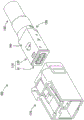
Fig. 1 is a perspective view of the connector of example 1, as viewed from obliquely above, in a state where the housing and the shield terminal are separated.
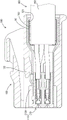
Fig. 2 is a side cross-sectional view of the connector assembled with the cable.
Fig. 3 is a partial perspective view of the terminal unit and the cable.
Fig. 4 is a partial perspective view of the terminal unit and the electric wire.
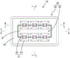
Fig. 5 is a front view of the terminal unit.
Fig. 6 is a sectional view taken along line a-a of fig. 5.
Fig. 7 is a sectional view taken along line B-B of fig. 5.
Fig. 8 is a cross-sectional view taken along line C-C of fig. 5 in a state where a tab of the counterpart terminal is inserted.
Fig. 9 is a perspective view of the holding member.
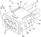
Fig. 10 is a perspective view of the front member.
Fig. 11 is a perspective view of the state before the terminal fitting is mounted to the holding member, as viewed from obliquely above.
Fig. 12 is a perspective view of a state in which the terminal fitting is attached to the holding member as viewed from obliquely above.
Fig. 13 is a partially enlarged view of fig. 12.
Fig. 14 is a perspective view of the 1 st shell.
Fig. 15 is a perspective view of the 2 nd housing.
Fig. 16 is a partial perspective view of the terminal unit and the cable according to example 2.
Fig. 17 is a side cross-sectional view of the terminal unit and the cable.
Fig. 18 is a perspective view of the holding member.
Fig. 19 is a perspective view of the front member.
Fig. 20 is a perspective view of the state in which the terminal fitting is attached to the holding member, viewed from obliquely above.
Detailed Description
In the present invention, the holding member may have a side wall portion that partitions the plurality of terminal accommodating chambers. The side wall portion may be formed with a restricting projection portion that is locked to the terminal fitting in the terminal receiving chamber so as to restrict the terminal fitting in the terminal receiving chamber from being disengaged from the opening portion.
According to this configuration, the terminal fitting attached to the terminal housing chamber is locked by the restricting projection so as to restrict the terminal fitting from coming off the opening portion, and therefore, the terminal fitting can be prevented from coming off the terminal housing chamber before the front member is assembled to the holding member.
In the present invention, the restricting projection may be disposed so as to be locked to the distal end portion of the terminal fitting.
According to this configuration, since the regulating protrusion is locked to the distal end portion of the terminal fitting, it is possible to regulate at least the distal end portion of the terminal fitting from coming off from the terminal accommodating chamber before the front member is assembled to the holding member. Therefore, when the front member is assembled to the holding member from the front, the front end portion of the terminal fitting detached from the terminal accommodating chamber can be prevented from interfering with the front member and interfering with the assembly.
In the present invention, the holding member may be formed with a rib which enters the slit to fill the hole.
According to this structure, in the structure in which the front member is assembled to the holding member, it is possible to prevent foreign matter from entering the slit formed in the front member. This prevents the elastic locking piece forming a part of the slit from being deformed by interference with foreign matter entering the slit.
< example 1>
Hereinafter, embodiment 1 embodying the present invention will be described with reference to fig. 1 to 15. In the following description, the left side in fig. 1 to 4 and 6 to 15 is defined as the front side with respect to the front-rear direction. The vertical directions are defined as upward and downward in the same manner as the directions shown in FIGS. 1 to 5 and 8 to 15. The left and right directions are defined as the left and right directions in fig. 5.
The connector 100 of embodiment 1 is a connecting member constituting a wire harness for a high-speed communication circuit of an automobile. As shown in fig. 1 and 2, the connector 100 includes a shield terminal 110 and a housing 120 that houses the shield terminal 110. The shield terminal 110 is configured by surrounding the terminal unit 10 with an outer conductor 130. As shown in fig. 7, the terminal unit 10 is configured by housing a plurality of terminal fittings 50 in the dielectric body 20.
As shown in fig. 2, a housing chamber 121 is formed inside the housing 120. Shield terminal 110 is inserted into housing chamber 121 from the rear of housing 120. A lance 122 is formed on the upper surface of the inside of the housing chamber 121, and the lance 122 is cantilevered forward and can elastically deflect upward.
As shown in fig. 1, the shield terminal 110 includes a terminal unit 10 and an outer conductor 130. As shown in fig. 1, the terminal unit 10 has a dielectric body 20 and a terminal fitting 50. As shown in fig. 7, the dielectric body 20 houses the terminal fitting 50, and the terminal fitting 50 is crimped to the end portion of the cable 160.
The cable 160 is a multi-core cable in which a plurality of electric wires 90 are collectively surrounded by a braided wire 161 and a sheath 162. The electric wire 90 is branched and led out from the end portions of the braided wire 161 and the sheath 162. A metal sleeve 163 is fitted over the end of the sheath 162, and the end of the braided wire 16 exposed outside the end of the sheath 162 is folded back in a backward reversed manner and overlaps the outer periphery of the sleeve 163. The axial direction of the electric wire 90 is parallel to the front-rear direction and orthogonal to the up-down direction and the left-right direction.
As shown in fig. 7 and 8, the dielectric body 20 accommodates a plurality of terminal fittings 50 in a state where the electric wires 90 are led out rearward. A plurality of insertion holes 21 are formed in the front surface of the dielectric body 20, and the plurality of insertion holes 21 allow insertion of the protruding pieces 95 of the counterpart terminals into the terminal accommodating chambers 34 described later. As shown in FIGS. 4 to 8, the dielectric body 20 includes: a holding member 30 to which the terminal fitting 50 is assembled; and a front member 40 assembled to the holding member 30 from the front of the holding member 30.
As shown in fig. 9, the holding member 30 includes: a substantially rectangular plate-shaped substrate portion 31; a front wall portion 32 connected to the front end portion of the substrate portion 31 upward and downward so as to be substantially orthogonal to the front end portion of the substrate portion 31; and four side walls 33 connected to the substrate portion 31 upward and downward so as to be substantially orthogonal to the substrate portion 31. The holding member 30 has a plurality of terminal accommodating chambers 34 divided into upper and lower stages and arranged in parallel in the left and right direction. The terminal accommodating chamber 34 is partitioned into a long groove shape extending in the front-rear direction by the front wall portion 32 and the four side wall portions 33. Openings 35 are formed in the upper and lower surfaces of the holding member 30, respectively, and the openings 35 enable the terminal fitting 50 to be mounted on the terminal accommodating chamber 34. A cutout 36 that is cut out so as to communicate with the opening 35 is formed in the front wall portion 32 of the terminal accommodating chamber 34. The cutout portion 36 is formed in a tapered shape such that a cutout width (cutout region) decreases toward the rear.
The side wall 33 has a restricting projection 37 formed on a surface thereof facing the terminal accommodating chamber 34, and the restricting projection 37 is locked to a front end portion (both right and left edges of the cutout 66) of the terminal fitting 50. The restricting protrusion 37 restricts the terminal fitting 50 from being removed from the opening 35 by the terminal fitting 50 locked in the terminal accommodating chamber 34. The upper side wall portion 33 has a rib 33A extending upward from its rear end side region, and the lower side wall portion 33 has a rib 33A extending downward from its rear end side region. The movement restricting portions 38 are formed in the substrate portion 31 so as to protrude inward of the terminal accommodating chambers 34, and the movement restricting portions 38 abut against the terminal fittings 50 to restrict the rearward movement of the terminal fittings 50. Projecting locking projections 39 are formed on both right and left outer side surfaces (outer surfaces of the side wall portions 33) of the holding member 30, and the locking projections 39 are locked to a front member 40 described later.
As shown in fig. 10, the front member 40 is a single member including a pair of upper and lower closing portions 41, a pair of left and right side plate portions 42, and a front wall portion 43. The pair of upper and lower closing portions 41 and 41 are formed integrally with the pair of left and right side plate portions 42 and 42, and individually close the upper-surface-side opening 35 and the lower-surface-side opening 35 in the holding member 30. The pair of left and right side plate portions 42, 42 cover both left and right side surfaces of the holding member 30, and are connected to both left and right end portions of the pair of upper and lower closing portions 41, 41. The front wall portion 43 is connected to the front end portions of the pair of closing portions 41, 41 and the front end portions of the pair of side plate portions 42, 42 so as to be substantially perpendicular thereto. Slits 44 are formed in the front member 40 at the boundary between the closing portion 41 and the side plate portion 42 (four corners of the front member 40) so as to be cut forward from the rear end portion. The rib 33A of the holding member 30 enters the slit 44 to fill the hole. The closing portion 41 is formed with an engaging portion 41A that protrudes upward and engages with a 1 st shell 140 described later.
In the side plate portions 42 and 42, a region where the slit 44 is formed in the front-rear direction (a portion from a position forward to a rear side of the center in the front-rear direction) serves as an elastic locking piece 42A, and the elastic locking piece 42A can be elastically deformed in the left-right direction and can be locked to the locking projection 39 of the holding member 30. The side plate portion 42 is formed with a locking hole 45, the locking hole 45 penetrates the side plate portion 42 in the plate thickness direction, and the locking protrusion 39 of the holding member 30 is locked to the locking hole 45. Locking portions 42B and 42C that protrude outward and are locked to a second case 150 described later are formed in the side plate portion 42.
A through hole 46 is formed in the front wall portion 43 and in a central portion of the wall surface, the through hole 46 penetrates the front wall portion 43 in the front-rear direction, and the front wall portion 32 of the holding member 30 enters the through hole 46. The through-hole 46 has formed therein: three recesses 47 cut upward at the upper edge (the front end of the upper closing portion 41); and three recesses 47 cut downward at the lower edge (the front end of the lower closing portion 41). The recess 47 is formed in a tapered shape such that a notch width (notch area) decreases toward the rear.
The terminal fitting 50 is a so-called female-type terminal fitting, and is integrally formed by punching out a conductive metal plate and then bending it. As shown in fig. 7, 8, 11 to 13, the terminal fitting 50 is elongated in the front-rear direction as a whole, and includes a box portion 60, a pressure-bonding portion 70, and a connecting portion 80. The box portion 60 is formed in a shape elongated in the front-rear direction as a whole, and is formed in a square tube shape in which a pair of elastic contact pieces 86 and 87 described later are housed. The crimp part 70 is crimped to the outer periphery of the electric wire 90. The coupling portion 80 is formed with a pair of elastic contact pieces 86 and 87, and is formed in a square cylindrical shape that couples the rear end of the box portion 60 and the front end of the pressure-bonding section 70. The box portion 60 and the connection portion 80 constitute a terminal body 51. When the projecting piece 95 of the mating terminal is inserted into the box portion 60 from the front (see fig. 8), the pair of elastic contact pieces 86 and 87 are brought into contact with the projecting piece 95 of the mating terminal in a state where the projecting piece 95 of the mating terminal is elastically sandwiched, and therefore the mating terminal and the terminal body portion 51 can be conductively connected.
A notch 65 penetrating the plate portion in the plate thickness direction is formed in the upper plate portion of the box portion 60. The elastic contact piece 86 enters the notch portion 65 when deformed, thereby avoiding interference between the tip end portion (protruding end portion) of the elastic contact piece 86 and the box portion 60. A notch 66 is formed in the lower plate portion of the box portion 60 to penetrate the plate portion in the plate thickness direction. The elastic contact piece 87 enters the cutout portion 66 when deformed, thereby avoiding interference between the tip end portion (protruding end portion) of the elastic contact piece 87 and the box portion 60.
As shown in fig. 7 and 8, the pressure-bonding section 70 is configured to be capable of conductively connecting the distal end of the wire 90 by pressure-bonding. The pressure-bonding section 70 includes: a wire barrel 71 crimped to the core wire 91 at the tip end of the wire 90; and an insulating tube 72 located behind the wire tube 71 and pressure-bonded to the covering 92 of the electric wire 90.
As shown in fig. 7 and 8, the coupling portion 80 includes a main body portion 81 and elastic contact pieces 86 and 87. The main body 81 is formed in a square tube shape. The elastic contact piece 86 is formed in a long plate shape extending forward so as to be continuous with a front end portion of the upper plate portion of the main body 81. The elastic contact piece 87 is formed in a long plate shape extending forward so as to be continuous with the front end portion of the lower plate portion of the main body 81.
As shown in fig. 1, the outer conductor 130 is formed by combining a half-divided 1 st shell 140 and a half-divided 2 nd shell 150 so as to sandwich the terminal unit 10. The upper tube 143 and the lower tube 153 formed at the rear end of the outer conductor 130 are conductively fixed to the braided wire 161 of the cable 160. Shield terminal 110 fixed to electric wire 90 is inserted into housing 120 from the rear and assembled to housing 120.
The 1 st case 140 includes an elongated plate-shaped upper plate portion 141, a pair of left and right side plate portions 142 connected to both left and right side edge portions of the upper plate portion 141 at substantially right angles, and an open tubular upper tube portion 143. A 1 st locking portion 144 that is formed in a substantially central portion of the upper plate portion 141 and that causes a portion of the upper plate portion 141 to be cut and punched upward in a protruding manner and locked to the housing 120 is formed. An upper locking hole 145 penetrating in the plate thickness direction and locking with the front member 40 is formed in front of the 1 st locking portion 144 of the upper plate portion 141. A 2 nd locking portion 146 that cuts and punches a part of the side plate portion 142 outward in a protruding shape and locks the side plate portion 142 to the housing 120 is formed at a substantially central portion of the side plate portion 142. A 3 rd locking portion 147 is formed in front of the 2 nd locking portion 146 of the side plate portion 142, and is cut and punched out to protrude inward and locked to the front member 40. A 4 th locking portion 148 is formed on the side plate 142 behind the 2 nd locking portion 146, and is cut and punched inward to protrude and locked to the 2 nd case 150.
The 2 nd shell 150 includes a long plate-shaped lower plate portion 151, a pair of left and right side plate portions 152 connected to both left and right side edge portions of the lower plate portion 151 at substantially right angles, and an open tubular lower tubular portion 153. A 1 st notch 154 that cuts rearward is formed at the front end of the side plate 152. A 2 nd notch 155 that is notched downward is formed behind the 1 st notch 154 of the side plate 152. A 2 nd through hole 156 penetrating in the plate thickness direction is formed in the rear of the 2 nd notch portion 155 of the side plate portion 152.
As shown in fig. 11 to 13, the terminal fitting 50 configured as described above is assembled to the holding member 30 from above or below. The three terminal fittings 50 enter the three terminal receiving chambers 34 on the upper layer of the holding member 30 from above through the opening portions 35, respectively. The three terminal fittings 50 enter the three terminal accommodating chambers 34 in the lower layer of the holding member 30 from below through the opening portions 35, respectively. The terminal fitting 50 entering the terminal receiving chamber 34 on the lower stage is in a state of being inverted in the vertical direction with respect to the direction of the terminal fitting 50 entering the terminal receiving chamber 34 on the upper stage. The pair of restricting projections 37, 37 are locked to the front end portions (the left and right edges of the cutout portion 66) of the terminal fitting 50 in the terminal accommodating chamber 34 in the upper stage from above. The pair of restricting projections 37, 37 are locked to the front end portions (the left and right edges of the cutout 66) of the terminal fitting 50 in the terminal accommodating chamber 34 of the lower stage from below. The terminal fitting 50 in the terminal accommodating chamber 34 is restricted from being removed from the opening 35 by the pair of restricting projections 37, 37. The rear end of the terminal body 51 is locked to the movement restricting portion 38 from the front. The terminal body 51 of the terminal fitting 50 in the terminal accommodating chamber 34 is restricted from moving backward by the movement restricting portion 38.
As shown in fig. 3 to 8, the front member 40 is assembled from the front to the holding member 30 to which the terminal fitting 50 is assembled, thereby constituting the terminal unit 10. During assembly, the left and right elastic locking pieces 42A, 42A of the front member 40 interfere with the locking projection 39 and are elastically deformed in the left and right directions, respectively, and the holding member 30 enters the front member 40. When the assembly is completed, as shown in fig. 4, the rib 33A enters the slit 44 of the front member 40 to fill the hole. The locking projection 39 of the holding member 30 enters the locking hole 45 of the front member 40, and the elastic locking piece 42A is elastically deformed and restored. The upper closing portion 41 closes the three openings 35 on the upper surface side of the holding member 30 from above. The lower closing portion 41 closes the three openings 35 on the lower surface side of the holding member 30 from below. The six terminal fittings 50 are accommodated in the dielectric body 20, and the terminal unit 10 is completed.
Since the front member 40 has a structure in which a pair of upper and lower closing portions 41 and 41 that individually close the upper-surface-side opening 35 and the lower-surface-side opening 35 are integrally formed, it is not necessary to use separate members that individually close the upper-surface-side opening 35 and the lower-surface-side opening 35. Therefore, the number of components constituting the connector 100 can be reduced. When a separate member is used to close the upper-surface-side opening 35 and the lower-surface-side opening 35, a dimensional tolerance in the vertical direction is generated in each member. Therefore, the dimensional tolerance in the vertical direction as a whole becomes large, and a gap may be generated between the members in the vertical direction, thereby causing rattling. The connector 100 of the present embodiment is configured such that the opening 35 on the upper surface side and the opening 35 on the lower surface side are closed with only one member (front member 40). Therefore, the accumulation of dimensional tolerances in the vertical direction is small, and a gap between the components in the vertical direction is less likely to occur, and rattling is less likely to occur.
As shown in fig. 4 and 5, the insertion hole 21 is formed by the notch portion 36 of the holding member 30 and the recess portion 47 of the front member 40. The insertion hole 21 is tapered such that the opening area decreases toward the rear. When the protruding piece 95 of the counterpart terminal enters the insertion hole 21, the protruding piece 95 is guided toward the center of the opening area of the insertion hole 21 by contacting the insertion hole 21.
The shield terminal 110 is configured by assembling the outer conductor 130 to the terminal unit 10. The 2 nd housing 150 is assembled to the terminal unit 10. The locking portions 42B and 42C of the front member 40 enter the 1 st notch portion 154 and the 2 nd notch portion 155 of the 2 nd case 150, respectively, and are locked. After the 2 nd housing 150 is assembled to the terminal unit 10, the 1 st housing 140 is assembled to the 2 nd housing 150 and the terminal unit 10. The locking portion 41A of the front member 40 enters the upper locking hole 145 of the 1 st case 140 and is locked. The 3 rd locking portion 147 of the 1 st shell 140 contacts and locks the locking portion 42C of the front member 40 from below. The 4 th locking part 148 of the 1 st case 140 enters the 2 nd through hole 156 of the 2 nd case 150 and is locked. The terminal unit 10, the 1 st case 140, and the 2 nd case 150 are held in an integrated state, and the shield terminal 110 is completed.
As shown in fig. 1 and 2, shield terminal 110 is inserted into housing 120 from the rear, and shield terminal 110 is accommodated in housing 120, thereby completing connector 100.
When the mating side connector is fitted to the connector 100, as shown in fig. 8, the projecting piece 95 of the mating side terminal inserted into the insertion hole 21 is inserted into the terminal accommodating chamber 34 from the front. The pair of elastic contact pieces 86, 87 are in contact with the protruding piece 95 in a state of elastically sandwiching the protruding piece 95, and the counterpart terminal and the terminal main body 51 are conductively connected. When the elastic contact pieces 86 and 87 elastically pinch the protruding piece 95 and deform, the tip portions thereof enter the notch portions 65 and 66, respectively. This can avoid interference between the elastic contact pieces 86 and 87 and the box portion 60.
The connector 100 of embodiment 1 is configured such that a pair of upper and lower closing portions 41 and 41 that individually close the opening 35 on the upper surface side and the opening 35 on the lower surface side are integrally formed in the front member 40 assembled to the holding member 30 from the front. Therefore, compared to a configuration using a plurality of separate members that close the upper surface side opening 35 and the lower surface side opening 35 from the upper surface side and the lower surface side, only the front member 40 that is a single member may be used, and the number of components can be reduced.
The holding member 30 has a side wall portion 33 that partitions a plurality of terminal receiving chambers 34. The side wall portion 33 is formed with a restricting projection 37, and the restricting projection 37 is locked to the terminal fitting 50 so as to restrict the terminal fitting 50 in the terminal accommodating chamber 34 from being detached from the opening portion 35.
According to this configuration, the restricting projection 37 is locked to the terminal fitting 50 so as to restrict the terminal fitting 50 attached to the terminal receiving chamber 34 from coming off from the opening 35, and thus the terminal fitting 50 can be prevented from coming off from the terminal receiving chamber 34 before the front member 40 is assembled to the holding member 30.
The restricting protrusion 37 is disposed so as to be locked to the front end portion (the edge portions on both the left and right sides of the notch portion 66) of the terminal fitting 50.
According to this configuration, since the regulating protrusion 37 is locked to the distal end portion of the terminal fitting 50 (the edge portions on both the left and right sides of the notch portion 66), it is possible to regulate at least the distal end portion of the terminal fitting 50 from coming out of the terminal accommodating chamber 34 before the front member 40 is assembled to the holding member 30. Therefore, when the front member 40 is assembled to the holding member 30 from the front, the front end portion of the terminal fitting 50 which is detached from the terminal accommodating chamber 34 can be prevented from interfering with the front member 40 and interfering with the assembly.
The front member 40 has a pair of left and right side plate portions 42, and the pair of left and right side plate portions 42, 42 are connected to both left and right end portions of the pair of upper and lower closing portions 41, 41 to cover both left and right side surfaces of the holding member 30. By forming the slit 44 in a form of being cut forward from the rear end of the front member 40, a part of the side plate portion 42 becomes an elastic locking piece 42A which can be elastically deformed in the left-right direction and can be locked to the holding member 30.
According to this configuration, since a part of the side plate portion 42 of the front member 40 is the elastic locking piece 42A that is elastically deformable in the left-right direction, the elastic locking piece 42A is deflected in the left-right direction, and thus the assembly resistance when the front member 40 is assembled to the holding member 30 from the front can be reduced.
The holding member 30 is formed with a rib 33A that enters the slit 44 and fills the hole.
According to this structure, in the structure in which the front member 40 is assembled to the holding member 30, it is possible to prevent foreign matter from entering the slit 44 formed in the front member 40. This prevents the elastic locking piece 42A constituting a part of the slit 44 from being deformed by interference with foreign matter entering the slit 44.
A plurality of insertion holes 21 are formed in the front surface of the dielectric body 20, and the plurality of insertion holes 21 allow insertion of the protruding pieces 95 of the counterpart terminals into the terminal accommodating chambers 34. The insertion hole 21 is composed of a notch 36 in which the front wall 32 of the holding member 30 is notched so as to communicate with the opening 35, and a recess 47 formed at the front end of the closing portion 41.
When the insertion hole 21 formed in the front surface of the dielectric body 20 is formed only by the front wall portion 32 of the holding member 30, a part of the insertion hole 21 is formed by a long and narrow beam portion for partitioning the insertion hole 21 and the opening portion 35, and the beam portion may be broken. As a countermeasure against this, a portion (recess 47) closest to the mouth portion 35 among the portions constituting the insertion hole 21 is constituted by the closing portion 41. This eliminates the need to leave an elongated beam portion in the holding member 30, and also eliminates the possibility of breakage.
< example 2>
FIGS. 16 to 20 show embodiment 2 of the present invention. The holding member 30 and the front member 40 in embodiment 2 are different from those in embodiment 1, and the other parts are the same as those in embodiment 1. Therefore, the same or corresponding components as those in embodiment 1 are denoted by the same reference numerals, and redundant description thereof is omitted.
In the case of example 2, as shown in fig. 17, the hole edge portion of the insertion hole 21 formed in the front surface of the dielectric body 20 is constituted only by the front wall portion 32 of the holding member 30. The insertion hole 21 is formed by a cutout portion 36A, and the cutout portion 36A is formed in a window shape by cutting the front wall portion 32 of the holding member 30 so as to communicate with the opening portion 35. The upper edge of the insertion hole 21 (cutout 36A) on the upper layer side is formed by a beam portion 32A (see fig. 18) extending in the left-right direction. The lower edge of the insertion hole 21 (the cutout portion 36A) on the lower layer side is formed by a beam portion 32A (see fig. 18) extending in the left-right direction. As shown in fig. 18, the opening 35 of the holding member 30 is composed of the beam portion 32A and the side wall portion 33. As shown in fig. 19, the recess 47 constituting the insertion hole 21 is not formed in the front member 40. The restricting projection 37A of the holding member 30 is formed on the side wall portion 33 so as to be engaged with the pressure-bonding section 70 of the terminal fitting 50 from above.
In the mechanism of example 2 as well, as in example 1, the terminal unit 10 is configured by assembling the front member 40 from the front with respect to the holding member 30 in which the terminal fitting 50 is assembled, as shown in fig. 16. The front member 40 is configured by integrally forming a pair of upper and lower closing portions 41 and 41 that individually close the upper-surface-side opening portion 35 and the lower-surface-side opening portion 35. Therefore, compared to a configuration using a plurality of separate members that close the upper surface side opening 35 and the lower surface side opening 35 from the upper surface side and the lower surface side, only the front member 40 that is a single member may be used, and the number of components can be reduced.
< other examples >
The present invention is not limited to the embodiments described above and illustrated in the drawings, and for example, the following embodiments are also included in the technical scope of the present invention.
(1) In embodiments 1 and 2, the number of terminal receiving chambers 34 in the upper layer of the holding member 30 may be other than three, and the number of terminal receiving chambers 34 in the lower layer may be other than three.
(2) In embodiments 1 and 2, the restricting projections 37 and 37A of the holding member 30 may be formed so as to be locked to the front end portions (the left and right edges of the cutout portion 66) and portions (the rear end portions and the like) other than the intermediate portion (the pressure-bonding section 70) of the terminal fitting 50.
(3) In embodiments 1 and 2, the slits of the front member 40 are not limited to the boundary portions between the closed portion 41 and the side plate portions 42 (four corner portions of the front member 40), and may be formed in the closed portion 41 or in the side plate portions 42.
Description of the reference numerals
20: dielectric body
21: inserting hole
30: holding member
32: front wall part
33: side wall part
33A: ribs
34: terminal receiving chamber
35: opening part
36. 36A: cut-out part
37. 37A: limiting projection
40: front component
41: closure part
42: side plate part
42A: elastic clamping stop piece
44: slit
47: concave part
50: terminal fitting
90: electric wire
95: tab
100: connector with a locking member
Claims (5)
1. A connector, characterized in that the connector is provided with:
a plurality of terminal parts connected with electric wires at a rear end portion; and
a dielectric body which accommodates the plurality of terminal fittings in a state where the electric wires are led out rearward,
the dielectric body has:
a holding member having a substantially rectangular plate-shaped substrate portion; and a front wall portion connected to the front end portion of the substrate portion in an upward and downward direction so as to be substantially orthogonal to the front end portion of the substrate portion, the holding member further including a plurality of terminal accommodating chambers arranged in parallel in a left-right direction and divided into upper and lower stages, and having openings formed in an upper surface and a lower surface, respectively, through which the terminal components can be mounted in the terminal accommodating chambers; and
a front member integrally formed with a pair of upper and lower closing portions that individually close the opening portion on the upper surface side and the opening portion on the lower surface side, the front member being assembled to the holding member from the front of the holding member,
a plurality of insertion holes are formed on the front surface of the dielectric body, the insertion holes allow the protruding sheets of the opposite side terminals to be inserted into the terminal receiving chambers,
the insertion hole is configured by a cutout portion in a form of cutting out the front wall portion of the holding member so as to communicate with the opening portion, and a recess portion formed at a distal end portion of the closing portion.
2. The connector of claim 1,
the holding member has a side wall portion partitioning the plurality of terminal receiving chambers,
a restricting projection is formed on the side wall portion, and the restricting projection is locked to the terminal fitting in the terminal receiving chamber so as to restrict the terminal fitting in the terminal receiving chamber from being detached from the opening portion.
3. The connector of claim 2,
the restricting protrusion is disposed so as to be locked to a distal end portion of the terminal fitting.
4. The connector according to any one of claims 1 to 3,
the front member has a pair of left and right side plate portions which are connected to both left and right end portions of the pair of upper and lower closing portions and which cover both left and right side surfaces of the holding member,
by forming the slit in a form of being cut forward from the rear end of the front member, a part of the side plate portion becomes an elastic locking piece which can be elastically deformed in the left-right direction and can be locked to the holding member.
5. The connector of claim 4,
the holding member is formed with a rib which enters the slit to fill the hole.
Applications Claiming Priority (3)
| Application Number | Priority Date | Filing Date | Title |
|---|---|---|---|
| JP2017135246A JP6816668B2 (en) | 2017-07-11 | 2017-07-11 | connector |
| JP2017-135246 | 2017-07-11 | ||
| PCT/JP2018/023447 WO2019012932A1 (en) | 2017-07-11 | 2018-06-20 | Connector |
Publications (2)
| Publication Number | Publication Date |
|---|---|
| CN111201678A CN111201678A (en) | 2020-05-26 |
| CN111201678B true CN111201678B (en) | 2021-05-28 |
Family
ID=65002426
Family Applications (1)
| Application Number | Title | Priority Date | Filing Date |
|---|---|---|---|
| CN201880043190.1A Active CN111201678B (en) | 2017-07-11 | 2018-06-20 | Connector with a locking member |
Country Status (5)
| Country | Link |
|---|---|
| US (1) | US11011865B2 (en) |
| JP (1) | JP6816668B2 (en) |
| CN (1) | CN111201678B (en) |
| DE (1) | DE112018003542T5 (en) |
| WO (1) | WO2019012932A1 (en) |
Families Citing this family (6)
| Publication number | Priority date | Publication date | Assignee | Title |
|---|---|---|---|---|
| JP6750525B2 (en) * | 2017-02-02 | 2020-09-02 | 株式会社オートネットワーク技術研究所 | Shield connector and male shield terminal |
| JP6750540B2 (en) * | 2017-03-10 | 2020-09-02 | 株式会社オートネットワーク技術研究所 | Shield terminal and shield connector |
| JP6816668B2 (en) * | 2017-07-11 | 2021-01-20 | 株式会社オートネットワーク技術研究所 | connector |
| JP7388264B2 (en) | 2020-03-24 | 2023-11-29 | 住友電装株式会社 | Connectors and cables with connectors |
| JP7447731B2 (en) | 2020-08-07 | 2024-03-12 | 住友電装株式会社 | connector |
| JP2022039033A (en) * | 2020-08-27 | 2022-03-10 | 住友電装株式会社 | connector |
Citations (3)
| Publication number | Priority date | Publication date | Assignee | Title |
|---|---|---|---|---|
| JPH0896864A (en) * | 1994-09-20 | 1996-04-12 | Yazaki Corp | Pressure contact connector |
| CN1513220A (en) * | 2001-06-04 | 2004-07-14 | ʸ����ҵ��ʽ���� | Wiring harness and wire harness manufacturing method |
| CN107077984A (en) * | 2014-11-21 | 2017-08-18 | 歌乐株式会社 | Button guide is constructed |
Family Cites Families (39)
| Publication number | Priority date | Publication date | Assignee | Title |
|---|---|---|---|---|
| JPS5755757Y2 (en) * | 1978-12-22 | 1982-12-01 | ||
| JPS61133978A (en) | 1984-12-03 | 1986-06-21 | 三菱電機株式会社 | Liquid crystal display unit |
| JPH0214137Y2 (en) * | 1985-02-12 | 1990-04-18 | ||
| JP2964446B2 (en) | 1994-11-22 | 1999-10-18 | 矢崎総業株式会社 | ID connector |
| JP3905731B2 (en) * | 2000-09-22 | 2007-04-18 | 矢崎総業株式会社 | Connector with lock security mechanism |
| JP4591228B2 (en) * | 2005-06-21 | 2010-12-01 | 住友電装株式会社 | connector |
| DE602006004519D1 (en) * | 2005-09-14 | 2009-02-12 | Sumitomo Wiring Systems | Connector, connector assembly and mounting method |
| JP4577209B2 (en) * | 2005-12-26 | 2010-11-10 | 住友電装株式会社 | connector |
| JP2007294200A (en) * | 2006-04-24 | 2007-11-08 | Yazaki Corp | Connector |
| JP2007335328A (en) * | 2006-06-16 | 2007-12-27 | Sumitomo Wiring Syst Ltd | Fitting member |
| JP4336358B2 (en) * | 2006-08-23 | 2009-09-30 | 矢崎総業株式会社 | Connector unit |
| JP5064131B2 (en) * | 2007-07-09 | 2012-10-31 | 矢崎総業株式会社 | connector |
| EP2023445B1 (en) * | 2007-08-10 | 2012-07-25 | Sumitomo Wiring Systems, Ltd. | A joint connector and an assembling method therefor |
| DE102009052772B4 (en) * | 2008-12-01 | 2014-02-13 | Sumitomo Wiring Systems, Ltd. | A connector |
| JP2011048945A (en) * | 2009-08-25 | 2011-03-10 | Sumitomo Wiring Syst Ltd | Connector |
| JP5532309B2 (en) * | 2010-03-17 | 2014-06-25 | 住友電装株式会社 | connector |
| JP2013016402A (en) * | 2011-07-06 | 2013-01-24 | Sumitomo Wiring Syst Ltd | Connector |
| US9160084B2 (en) * | 2011-10-28 | 2015-10-13 | Sumitomo Wiring Systems, Ltd. | Connector |
| JP5754412B2 (en) | 2012-04-26 | 2015-07-29 | 住友電装株式会社 | connector |
| JP5922528B2 (en) * | 2012-08-09 | 2016-05-24 | タイコエレクトロニクスジャパン合同会社 | Electrical connector assembly and housing |
| WO2014104122A1 (en) * | 2012-12-27 | 2014-07-03 | 住友電装株式会社 | Waterproof container |
| JP2015060628A (en) * | 2013-09-17 | 2015-03-30 | 住友電装株式会社 | Connector |
| JP2015090843A (en) * | 2013-11-07 | 2015-05-11 | 矢崎総業株式会社 | Water cutoff structure for connector |
| JP6036661B2 (en) * | 2013-11-19 | 2016-11-30 | 住友電装株式会社 | Waterproof connector |
| JP6342708B2 (en) * | 2014-05-15 | 2018-06-13 | 矢崎総業株式会社 | Connector and terminal fitting connection structure |
| EP2991169B1 (en) * | 2014-08-27 | 2018-01-31 | TE Connectivity Nederland B.V. | Connector system |
| JP2016051634A (en) * | 2014-09-01 | 2016-04-11 | 住友電装株式会社 | connector |
| JP2016054057A (en) * | 2014-09-03 | 2016-04-14 | 株式会社ユニゾン | connector |
| JP6737011B2 (en) * | 2016-07-01 | 2020-08-05 | 株式会社オートネットワーク技術研究所 | Shielded connector |
| JP2018018583A (en) * | 2016-07-25 | 2018-02-01 | 住友電装株式会社 | connector |
| JP2018018584A (en) * | 2016-07-25 | 2018-02-01 | 住友電装株式会社 | connector |
| JP2019016531A (en) * | 2017-07-07 | 2019-01-31 | 株式会社オートネットワーク技術研究所 | Board connector, and connection structure between circuit board and board connector |
| JP6816668B2 (en) * | 2017-07-11 | 2021-01-20 | 株式会社オートネットワーク技術研究所 | connector |
| JP6819510B2 (en) * | 2017-08-16 | 2021-01-27 | 株式会社オートネットワーク技術研究所 | connector |
| JP2019091610A (en) * | 2017-11-14 | 2019-06-13 | 住友電装株式会社 | connector |
| JP6616815B2 (en) * | 2017-12-20 | 2019-12-04 | 矢崎総業株式会社 | Connector and electric wire with connector |
| JP2019153502A (en) * | 2018-03-05 | 2019-09-12 | 住友電装株式会社 | connector |
| JP7054452B2 (en) * | 2018-11-02 | 2022-04-14 | 住友電装株式会社 | connector |
| JP2020087844A (en) * | 2018-11-30 | 2020-06-04 | 住友電装株式会社 | Terminal fitting |
-
2017
- 2017-07-11 JP JP2017135246A patent/JP6816668B2/en active Active
-
2018
- 2018-06-20 CN CN201880043190.1A patent/CN111201678B/en active Active
- 2018-06-20 WO PCT/JP2018/023447 patent/WO2019012932A1/en active Application Filing
- 2018-06-20 DE DE112018003542.5T patent/DE112018003542T5/en active Pending
- 2018-06-20 US US16/629,158 patent/US11011865B2/en active Active
Patent Citations (3)
| Publication number | Priority date | Publication date | Assignee | Title |
|---|---|---|---|---|
| JPH0896864A (en) * | 1994-09-20 | 1996-04-12 | Yazaki Corp | Pressure contact connector |
| CN1513220A (en) * | 2001-06-04 | 2004-07-14 | ʸ����ҵ��ʽ���� | Wiring harness and wire harness manufacturing method |
| CN107077984A (en) * | 2014-11-21 | 2017-08-18 | 歌乐株式会社 | Button guide is constructed |
Also Published As
| Publication number | Publication date |
|---|---|
| JP2019016575A (en) | 2019-01-31 |
| DE112018003542T5 (en) | 2020-04-09 |
| WO2019012932A1 (en) | 2019-01-17 |
| CN111201678A (en) | 2020-05-26 |
| US11011865B2 (en) | 2021-05-18 |
| JP6816668B2 (en) | 2021-01-20 |
| US20200136294A1 (en) | 2020-04-30 |
Similar Documents
| Publication | Publication Date | Title |
|---|---|---|
| CN111201678B (en) | Connector with a locking member | |
| US10931056B2 (en) | Connector | |
| US10644416B2 (en) | Connector | |
| JP6525221B2 (en) | connector | |
| CN110383591B (en) | Shielding terminal and shielding connector | |
| CN109417251B (en) | Shielded connector | |
| CN110301072B (en) | Connector with a locking member | |
| US9017108B2 (en) | Electrical connector | |
| US11088486B2 (en) | Shield terminal and shield connector | |
| CN110323613B (en) | Connector and terminal component | |
| WO2018168368A1 (en) | Terminal unit and connector | |
| JP6315339B2 (en) | connector | |
| JP7236034B2 (en) | branch connector | |
| CN110870143B (en) | Terminal fitting | |
| CN111480270B (en) | Shielding terminal | |
| CN219067403U (en) | Connector assembly | |
| WO2022054455A1 (en) | Shield connector | |
| WO2022264799A1 (en) | Connector | |
| US20230101364A1 (en) | Connector | |
| US20220109267A1 (en) | Connector | |
| JP2023077162A (en) | connector | |
| JP2022108785A (en) | connector | |
| CN112952410A (en) | Connector with a locking member | |
| JP2011165474A (en) | Connector for wire harness connection |
Legal Events
| Date | Code | Title | Description |
|---|---|---|---|
| PB01 | Publication | ||
| PB01 | Publication | ||
| SE01 | Entry into force of request for substantive examination | ||
| SE01 | Entry into force of request for substantive examination | ||
| GR01 | Patent grant | ||
| GR01 | Patent grant |