JP6750525B2 - Shield connector and male shield terminal - Google Patents
Shield connector and male shield terminal Download PDFInfo
- Publication number
- JP6750525B2 JP6750525B2 JP2017017180A JP2017017180A JP6750525B2 JP 6750525 B2 JP6750525 B2 JP 6750525B2 JP 2017017180 A JP2017017180 A JP 2017017180A JP 2017017180 A JP2017017180 A JP 2017017180A JP 6750525 B2 JP6750525 B2 JP 6750525B2
- Authority
- JP
- Japan
- Prior art keywords
- male
- female
- housing
- outer conductor
- conductor
- Prior art date
- Legal status (The legal status is an assumption and is not a legal conclusion. Google has not performed a legal analysis and makes no representation as to the accuracy of the status listed.)
- Active
Links
Images


Classifications
-
- H—ELECTRICITY
- H01—ELECTRIC ELEMENTS
- H01R—ELECTRICALLY-CONDUCTIVE CONNECTIONS; STRUCTURAL ASSOCIATIONS OF A PLURALITY OF MUTUALLY-INSULATED ELECTRICAL CONNECTING ELEMENTS; COUPLING DEVICES; CURRENT COLLECTORS
- H01R13/00—Details of coupling devices of the kinds covered by groups H01R12/70 or H01R24/00 - H01R33/00
- H01R13/648—Protective earth or shield arrangements on coupling devices, e.g. anti-static shielding
- H01R13/658—High frequency shielding arrangements, e.g. against EMI [Electro-Magnetic Interference] or EMP [Electro-Magnetic Pulse]
- H01R13/6591—Specific features or arrangements of connection of shield to conductive members
- H01R13/6592—Specific features or arrangements of connection of shield to conductive members the conductive member being a shielded cable
- H01R13/6593—Specific features or arrangements of connection of shield to conductive members the conductive member being a shielded cable the shield being composed of different pieces
-
- H—ELECTRICITY
- H01—ELECTRIC ELEMENTS
- H01R—ELECTRICALLY-CONDUCTIVE CONNECTIONS; STRUCTURAL ASSOCIATIONS OF A PLURALITY OF MUTUALLY-INSULATED ELECTRICAL CONNECTING ELEMENTS; COUPLING DEVICES; CURRENT COLLECTORS
- H01R13/00—Details of coupling devices of the kinds covered by groups H01R12/70 or H01R24/00 - H01R33/00
- H01R13/648—Protective earth or shield arrangements on coupling devices, e.g. anti-static shielding
- H01R13/658—High frequency shielding arrangements, e.g. against EMI [Electro-Magnetic Interference] or EMP [Electro-Magnetic Pulse]
- H01R13/6581—Shield structure
- H01R13/6582—Shield structure with resilient means for engaging mating connector
-
- H—ELECTRICITY
- H01—ELECTRIC ELEMENTS
- H01R—ELECTRICALLY-CONDUCTIVE CONNECTIONS; STRUCTURAL ASSOCIATIONS OF A PLURALITY OF MUTUALLY-INSULATED ELECTRICAL CONNECTING ELEMENTS; COUPLING DEVICES; CURRENT COLLECTORS
- H01R2107/00—Four or more poles
Description
本発明は、シールドコネクタ及び雄側シールド端子に関するものである。 The present invention relates to a shield connector and a male side shield terminal.
特許文献1には、メスハウジングにメスアウター端子とメスインナー端子を設け、オスハウジングにオスアウター端子とオスインナー端子を設け、メスハウジングとオスハウジングを嵌合することにより、メスインナー端子とオスインナー端子を接続するコネクタが開示されている。このコネクタでは、メスハウジングとオスハウジングが嵌合すると、メスアウター端子とオスアウター端子が接続される。そして、メスアウター端子の半円筒部とオスアウター端子の半円筒部が円筒形をなすように合体することで、メスインナー端子とオスインナー端子との接触部位が全周に亘ってシールドされるようになっている。 In Patent Document 1, a female outer terminal and a female inner terminal are provided in a female housing, a male outer terminal and a male inner terminal are provided in a male housing, and a female inner terminal and a male inner terminal are provided by fitting the female housing and the male housing. A connector for connecting terminals is disclosed. In this connector, when the female housing and the male housing are fitted together, the female outer terminal and the male outer terminal are connected. Then, the semi-cylindrical portion of the female outer terminal and the semi-cylindrical portion of the male outer terminal are combined so as to form a cylindrical shape, so that the contact portion between the female inner terminal and the male inner terminal is shielded over the entire circumference. It has become.
メス側の半円筒部とオス側の半円筒部は、単に合体しているだけであるから、半円筒部同士の間に隙間が空いてシールド機能が低下することが懸念される。この対策としては、一方の半円筒部に弾性接触片を形成し、この弾性接触片を相手側の半円筒部に弾性的に接触させる構成が考えられる。しかし、半円筒部は、弾性接触片の弾力によって径方向外方へ拡開変形可能な形状をなしているため、弾性接触片を形成しても、接触信頼性を高めることができず、シールド機能の低下は回避できない。 Since the female-side semi-cylindrical portion and the male-side semi-cylindrical portion are simply united, there is a concern that a gap is left between the semi-cylindrical portions and the shield function is deteriorated. As a countermeasure against this, it is conceivable that an elastic contact piece is formed on one of the semi-cylindrical parts and the elastic contact piece is elastically brought into contact with the semi-cylindrical part on the other side. However, since the semi-cylindrical portion has a shape that can be expanded and deformed radially outward by the elastic force of the elastic contact piece, even if the elastic contact piece is formed, the contact reliability cannot be improved and the shield is shielded. A decline in function cannot be avoided.
本発明は上記のような事情に基づいて完成されたものであって、シールド機能の信頼性向上を図ることを目的とする。 The present invention has been completed based on the above circumstances, and an object thereof is to improve the reliability of the shield function.
第1の発明は、
雌側ハウジングと、
前記雌側ハウジングに取り付けられた雌側シールド端子と、
前記雌側シールド端子を構成する雌側内導体と、
雌側誘電体を介して前記雌側内導体を包囲する雌側外導体と、
前記雌側ハウジングと嵌合可能な雄側ハウジングと、
前記雄側ハウジングに取り付けられた雄側シールド端子と、
前記雄側シールド端子を構成し、前記雌側ハウジングと前記雄側ハウジングが嵌合することで前記雌側内導体と接続する雄側内導体と、
雄側誘電体を介して前記雄側内導体を包囲し、前記雌側ハウジングと前記雄側ハウジングが嵌合することで前記雌側外導体と接触する雄側外導体と、
前記雄側外導体に形成され、前記雌側ハウジングと前記雄側ハウジングが嵌合した状態で前記雌側外導体を包囲する筒部と、
前記雌側外導体と前記雄側外導体のうち少なくとも一方に形成され、前記雌側外導体の外周と前記筒部の内周を弾性的に接続する弾性接触片とを備え、
前記筒部は、全周に亘って繋がった形態であることで拡開変形が規制されているところに特徴を有する。
The first invention is
A female housing,
A female shield terminal attached to the female housing,
A female inner conductor that constitutes the female shield terminal,
A female outer conductor that surrounds the female inner conductor via a female dielectric;
A male housing that is engageable with the female housing;
A male shield terminal attached to the male housing,
A male inner conductor that constitutes the male shield terminal, and is connected to the female inner conductor by fitting the female housing and the male housing,
A male outer conductor that surrounds the male inner conductor via a male dielectric, and is brought into contact with the female outer conductor by fitting the female housing and the male housing,
A tubular portion that is formed on the male-side outer conductor and that surrounds the female-side outer conductor in a state where the female-side housing and the male-side housing are fitted together;
At least one of the female-side outer conductor and the male-side outer conductor, comprising an elastic contact piece that elastically connects the outer periphery of the female-side outer conductor and the inner periphery of the tubular portion,
The cylindrical portion is characterized in that the expansion deformation is restricted because the cylindrical portion is connected over the entire circumference.
第2の発明は、
雌側ハウジングと嵌合可能な雄側ハウジングに取り付けられる雄側シールド端子であって、
前記雌側ハウジングに設けた前記雌側内導体と接続可能な雄側内導体と、
雄側誘電体を介して前記雄側内導体を包囲し、前記雌側ハウジングに設けた雌側外導体と接触可能な雄側外導体と、
前記雄側外導体に形成され、前記雌側ハウジングと前記雄側ハウジングが嵌合した状態で前記雌側外導体を包囲する筒部と、
前記筒部に形成され、前記雌側外導体の外周に対して弾性的に接続する弾性接触片とを備え、
前記筒部は、全周に亘って繋がった形態であることで拡開変形が規制されているところに特徴を有する。
The second invention is
A male side shield terminal attached to a male side housing that can be fitted with a female side housing,
A male inner conductor connectable to the female inner conductor provided in the female housing;
A male-side outer conductor that surrounds the male-side inner conductor via a male-side dielectric and is capable of contacting the female-side outer conductor provided in the female-side housing,
A tubular portion that is formed on the male-side outer conductor and that surrounds the female-side outer conductor in a state where the female-side housing and the male-side housing are fitted together;
An elastic contact piece formed on the cylindrical portion and elastically connected to the outer circumference of the female outer conductor,
The cylindrical portion is characterized in that the expansion deformation is restricted by being in the form of being connected over the entire circumference.
雌側外導体の外周と雄側外導体の筒部が弾性接触片によって接続された状態では、弾性接触片の弾力が筒部に対して拡開変形させる方向の力として作用する。しかし、筒部は、全周に亘って繋がった形態であることで拡開変形を規制されているので、雌側外導体と雄側外導体との間の接触信頼性に優れている。 When the outer circumference of the female outer conductor and the cylindrical portion of the male outer conductor are connected by the elastic contact piece, the elastic force of the elastic contact piece acts as a force in the direction of expanding and deforming the cylindrical portion. However, since the cylindrical portion is connected over the entire circumference to prevent expansion and deformation, the contact reliability between the female outer conductor and the male outer conductor is excellent.
第1及び第2の発明は、前記筒部が、前記雄側内導体のタブを包囲していてもよい。この構成によれば、雄側シールド端子を雄側ハウジングから外した状態において、タブに対する異物の干渉を筒部によって防止することができる。 In the first and second aspects, the tubular portion may surround the tab of the male-side inner conductor. According to this configuration, in the state where the male side shield terminal is removed from the male side housing, it is possible to prevent foreign matter from interfering with the tab by the tubular portion.
第1及び第2の発明は、前記雄側外導体が、前記筒部が形成された筒状部材と、電線のシールド層に圧着される圧着部が形成された圧着用部材とを備えて構成されていてもよい。この構成によれば、形状が複雑な圧着部を、筒状部材とは別体である圧着用部材に形成したので、筒状部材の形状を簡素化することができる。これにより、筒状部材の設計に際しては、筒部の拡開変形を規制するための機能を優先させることができるので、筒部の拡開変形を確実に防止することができる。 1st and 2nd invention is comprised with the said male side outer conductor provided with the cylindrical member in which the said cylindrical part was formed, and the crimping member in which the crimping part crimped to the shield layer of an electric wire was formed. It may have been done. According to this configuration, since the crimping portion having a complicated shape is formed in the crimping member which is a separate body from the tubular member, the shape of the tubular member can be simplified. Thus, when designing the tubular member, the function for restricting the expansion deformation of the tubular portion can be prioritized, so that the expansion deformation of the tubular portion can be reliably prevented.
第1の発明は、前記雌側ハウジングには、前記雌側ハウジングと前記雄側ハウジングが嵌合した状態で前記筒部の外周面を当接させる当接面が形成されていてもよい。この構成によれば、雌側ハウジングと雄側ハウジングが嵌合した状態では、筒部の拡開変形が、雌側ハウジングの当接面によっても規制されるので、雌側外導体と雄側外導体の接触信頼性が向上する。 In the first invention, the female housing may be formed with an abutting surface that abuts an outer peripheral surface of the tubular portion in a state where the female housing and the male housing are fitted to each other. According to this configuration, in the state where the female housing and the male housing are fitted together, the expanding deformation of the tubular portion is also restricted by the contact surface of the female housing, so the female outer conductor and the male outer housing The contact reliability of the conductor is improved.
<実施例1>
以下、本発明を具体化した実施例1を図1〜図13を参照して説明する。本実施例のシールドコネクタは、互いに嵌合離脱が可能な雄側コネクタMと雌側コネクタFとを備えて構成されている。尚、以下の説明において、雄側コネクタMの前後の方向については、図1〜4における左方を前方と定義する。上下の方向については、図1,2,4,5にあらわれる向きを、そのまま上方、下方と定義する。
<Example 1>
Hereinafter, a first embodiment embodying the present invention will be described with reference to FIGS. The shielded connector of the present embodiment is provided with a male connector M and a female connector F that can be fitted and removed from each other. In the following description, with respect to the front-back direction of the male connector M, the left side in FIGS. 1 to 4 is defined as the front side. Regarding the up and down directions, the directions appearing in FIGS. 1, 2, 4, and 5 are defined as upper and lower as they are.
雄側コネクタMは、合成樹脂製の雄側ハウジング10と、雄側シールド端子20とを備えて構成されている。雄側ハウジング10には、その前後両端に開放された端子収容部11と、端子収容部11から前方へ角筒状に延出したフード部12とが形成されている。端子収容部11の内部には、雄側シールド端子20を抜止めするためのランス13が形成され、フード部12の外面にはロック突起14が形成されている。
The male connector M includes a
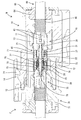
雄側シールド端子20は、図5に示すように、雄側外導体21と、雄側誘電体31と、複数の雄側内導体37とを組み付けて構成されている。雄側外導体21は、筒状部材22とロア部材40(請求項に記載の圧着用部材)とアッパ部材47との3部品を組み付けて構成されている。
As shown in FIG. 5, the male
筒状部材22は、所定形状の金属板材に曲げ加工等を施すことにより全体として概ね角筒状に成形されたものである。図6に示すように、筒状部材22を構成する下面部においては、金属板材の一方の端縁部に形成した略台形状の凹部23と、金属板材の他方の端縁部に形成した略台形状の凸部24とが離脱規制状態に嵌合されている。この凹部23と凸部24の嵌合により、筒状部材22は、周方向において全周に亘って繋がった形態に保持され、拡開変形しないようになっている。
The
筒状部材22のうち前端側領域は、雌側外導体76との接触手段として機能する略角筒状の筒部25となっている。筒部25を構成する4つの板部には、夫々、板部の一部を切り起こした形態であって、斜め内側前方へ片持ち状に延出した形態の弾性接触片26が形成されている。これらの弾性接触片26は、雌側外導体76の外周面に対し弾性的に当接するようになっている。弾性接触片26は、凹部23と凸部24よりも前方の領域に配されている。
A front end side region of the
筒状部材22の後端側領域は、雄側誘電体31を保持するための略角筒状の保持部27として機能する。図5,8に示すように、保持部27を構成する左右両側板部には夫々、窓孔状の第1係止部28と、保持部27の後端縁を切欠した形態の第2係止部29と、窓孔状の第3係止部30とが形成されている。
The rear end side region of the
雄側誘電体31は、合成樹脂製であり、全体としてブロック状をなす。雄側誘電体31の内部には、前後方向に細長く貫通した形態の複数の収容孔32が形成されている。雄側誘電体31の左右両側面には、夫々、第1係止突起33と第2係止突起34と第4係止突起35と第1ガイドピン36が形成されている。
The
雄側内導体37は、金属材料からなり、全体として前後方向に細長い形状である。雄側内導体37の前端部には、前方へ片持ち状に延出した形態の細長いタブ38が形成されている。雄側内導体37の後端部には、電線接続部39が形成されている。
The male
ロア部材40は、金属板材に曲げ加工等を施して成形されたものである。ロア部材40の前端側領域は、底板部の左右両側縁から左右一対の側板部を立ち上げた形態のロアシェル41となっている。ロアシェル41の底板部には、その前端縁に沿ってリブ状に突出し、且つ側面視形状が段差状に屈曲した形態の第1支点部42が形成されている。ロアシェル41の左右両側板部には、夫々、側板部の前端縁から斜め下後方へ切欠した形態の第1ガイド溝45Fと、窓孔状の第4係止部43と、窓孔状の第5係止部44と、側板部の後端縁から斜め下前方へ切欠した形態第2ガイド溝45Rが形成されている。ロア部材40の後端側領域は、オープンバレル状の圧着部46となっている。
The
アッパ部材47は、金属板材に曲げ加工等を施して成形されたものである。アッパ部材47の前端側領域は、上板部の左右両側縁から左右一対の側板部を下方へ延出させた形態のアッパシェル48となっている。アッパシェル48の上板部には、その前端縁に沿ってリブ状に突出し、且つ側面視形状が段差状に屈曲した形態の第2支点部49が形成されている。アッパシェル48の左右両側板部の内面には、夫々、第3係止突起50と、第5係止突起51と、第2ガイドピン52が形成されている。アッパ部材47の後端側領域は、ロア部材40の圧着部46に対し上方から対向するカバー部53となっている。
The
次に、本実施例のシールドコネクタの組付け手順を説明する。まず、図7に示すように、雄側誘電体31に対し、その後方から複数の雄側内導体37を収容孔32内に挿入して取り付ける。雄側内導体37を雄側誘電体31に取り付けた状態では、図4,8に示すように、タブ38が雄側誘電体31の前端面から前方へ突出し、電線接続部39が雄側誘電体31の上面と下面において外部へ露出した状態となる。
Next, a procedure for assembling the shield connector of this embodiment will be described. First, as shown in FIG. 7, a plurality of male
次に、筒状部材22に対し、その後方から雄側誘電体31を組み付ける。図4,9に示すように、取り付けた状態では、雄側誘電体31の前端側領域が、筒状部材22の保持部27内に嵌合され、複数のタブ38が筒部25によって一括して包囲される。また、筒状部材22と雄側誘電体31は、第1係止突起33と第1係止部28との係止と、第2係止突起34と第2係止部29との係止により、組付け状態に保持されている。取り付け状態では、第4係止突起35と第1ガイドピン36と雄側内導体37の電線接続部39が筒状部材22の後方に露出している。
Next, the
この後、各雄側内導体37の電線接続部39には、夫々、多芯電線60(請求項に記載の電線)を構成する複数本の被覆電線61の前端部が、半田付けにより導通可能に接続される。多芯電線60は、複数本の細い被覆電線61と、複数本の被覆電線61を束ねた状態で包囲する編組線等からにるシールド層62と、シールド層62を包囲する円筒状のシース63とを備えて構成されている。シールド層62の前端部は、後方へ折り返されてシース63の外周を覆っている。複数本の被覆電線61は、シース63及びシールド層62の前端から前方へ延出されている。
After that, the front end portions of the plurality of covered
被覆電線61を電線接続部39に接続した後、筒状部材22と雄側誘電体31にロア部材40を組み付ける。取り付けに際しては、図10に示すように、ロア部材40の第1支点部45Fを筒状部材22の保持部27の後端の下縁部に係止し、その係止位置を支点としてロア部材40を上方へ揺動させる。ロア部材40を揺動する過程では、第1ガイド溝42と第1ガイドピン36が摺動することで、ロア部材40の揺動軌跡が安定する。
After connecting the covered
図11に示すように、ロア部材40と筒状部材22と雄側誘電体31は、第4係止突起35と第4係止部43との係止と、第1ガイド溝45Fと第1ガイドピン36との嵌合により、組付け状態に保持される。ロア部材40を筒状部材22と雄側誘電体31に取り付けた状態では、圧着部46がシールド層62の外周のうち下面側領域を覆う状態となる。
As shown in FIG. 11, the
この後、筒状部材22と雄側誘電体31とロア部材40にアッパ部材47を組み付ける。取り付けに際しては、図12に示すように、アッパ部材47の第2支点部49を筒状部材22の保持部27の後端の上縁部に係止し、その係止位置を支点としてアッパ部材47を下方へ揺動させる。アッパ部材47を揺動する過程では、第2ガイド溝45Rと第2ガイドピン52が摺動することで、アッパ部材47の揺動軌跡が安定する。
Then, the
アッパ部材47と筒状部材22とロア部材40は、第3係止突起50と第3係止部30との係止と、第5係止突起51と第5係止部44との係止と、第2ガイド溝45Rと第2ガイドピン52との嵌合により、組付け状態に保持される。アッパ部材47を筒状部材22とロア部材40に取り付けた状態では、カバー部53が、シールド層62の外周のうち上面側領域を覆う状態となる。次に、図13に示すように、圧着部46をカバー部53の外周にカシメ付けることにより、圧着部46とカバー部53が、シールド層62の外周に対し全周に亘って包囲し且つ導通可能な状態で固着され、雄側シールド端子20の組付けが完了する。
The
この後、雄側ハウジング10に対し後方から雄側シールド端子20を挿入し、ランス13により抜止め状態に保持する。次に、予め多芯電線60に外嵌されているゴム栓64とリヤホルダ65を雄側ハウジング10の後端部に取り付ければ、雄側コネクタMの組付けが完了する。
Thereafter, the
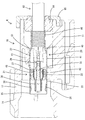
雌側コネクタFは、合成樹脂製の雌側ハウジング70と、雌側シールド端子75と備えて構成されている。図2,3に示すように、雌側ハウジング70は、雌側シールド端子75を収容するハウジング本体71と、ハウジング本体71を包囲する筒状嵌合部72とを備えている。ハウジング本体71には、雌側外導体76の外周の前端部に対し、僅かな隙間を空けて対向する4面の当接面73が形成されている。筒状嵌合部72にはロックアーム74が形成されている。図2に示すように、雌側シールド端子75は、略角筒状の雌側外導体76と、雌側外導体76に収容された雌側誘電体77と、雌側誘電体77内周に収容された複数の雌側内導体78とを備えて構成されている。
The female connector F includes a
雄側コネクタMと雌側コネクタFを嵌合すると、ハウジング本体71部がフード部12内に収容されるとともに、筒状嵌合部72がフード部12を包囲し、ロックアーム74とロック突起14との係止によって両コネクタF,Mが嵌合状態にロックされる。両コネクタF,Mが嵌合した状態では、雄側内導体37のタブ38が雌側内導体78に接続するとともに、雄側外導体21の弾性接触片26が雌側外導体76の外周に弾性接触する。
When the male side connector M and the female side connector F are fitted together, the
弾性接触片26は、筒部25を構成する4つの板部に形成されているので、雌側外導体76の外周に対し上下左右の4方向から当接する。弾性接触片26の後端は筒部25に支持されているため、弾性接触片26が雌側外導体76の外周に弾性接触すると、弾性接触片26の弾性復元力によって筒部25には径方向外方(上下方向及び左右方向)への反力が作用する。
Since the
しかし、筒部25は、凹部23と凸部24の嵌合により全周に亘って拡開変形しないように繋がった形態となっているので、筒部25は所期の略角筒形状を保つ。また、筒部25の外周の4面は、雌側ハウジング70の4つの当接面73に対し当接又は接近して対向しているので、万一筒部25が上下方向又は左右方向へ拡開変位しようとしても、当接面73への当接によって拡開変位が規制される。これにより、雌側外導体76に対する弾性接触片26の接触圧が確保され、雄側外導体21と雌側外導体76が確実に導通可能に接続される。
However, since the
上述のように、本実施例のシールドコネクタは、雄側コネクタMと雌側コネクタFとを備えて構成されている。雌側コネクタFは、雌側ハウジング70と、雌側ハウジング70に取り付けられた雌側シールド端子75と、雌側シールド端子75を構成する雌側内導体78と、雌側誘電体77を介して雌側内導体78を包囲する雌側外導体76とを備えている。
As described above, the shield connector of this embodiment is configured to include the male side connector M and the female side connector F. The female connector F includes a
雄側コネクタMは、雌側ハウジング70と嵌合可能な雄側ハウジング10と、雄側ハウジング10に取り付けられた雄側シールド端子20と、雄側シールド端子20を構成し、雌側ハウジング70と雄側ハウジング10が嵌合することで雌側内導体78と接続する雄側内導体37と、雄側誘電体31を介して雄側内導体37を包囲し、雌側ハウジング70と雄側ハウジング10が嵌合することで雌側外導体76と接触する雄側外導体21とを備えている。
The male-side connector M constitutes a male-
そして、雄側外導体21には、雌側ハウジング70と雄側ハウジング10が嵌合した状態で雌側外導体76を包囲する筒部25が形成されており、雄側外導体21の筒部22には、雌側外導体76の外周と筒部25の内周を弾性的に接続する弾性接触片26が形成されている。筒部25は、全周に亘って繋がった形態であることで拡開変形が規制されている。
The male
雌側外導体76の外周と雄側外導体21の筒部25が弾性接触片26によって接続された状態では、弾性接触片26の弾力が筒部25に対して拡開変形させる方向の力として作用する。しかし、筒部25は、全周に亘って繋がった形態であることで拡開変形を規制されているので、雌側外導体76と雄側外導体21との間の接触信頼性に優れている。
In a state where the outer circumference of the female
しかも、雌側ハウジング70には、雌側ハウジング70と雄側ハウジング10が嵌合した状態で筒部25の外周面を当接させる当接面73が形成されている。この構成によれば、雌側ハウジング70と雄側ハウジング10が嵌合した状態では、筒部25の拡開変形が、雌側ハウジング70の当接面73によっても規制されるので、雌側外導体76と雄側外導体21の接触信頼性が向上する。
Moreover, the
また、雄側外導体21は、筒部25が形成された筒状部材22と、多芯電線60のシールド層62に圧着される圧着部46が形成されたロア部材40(圧着用部材)とを備えて構成されていてもよい。この構成によれば、形状が複雑な圧着部46を、筒状部材22とは別体であるロア部材40に形成したので、筒状部材22の形状を簡素化することができる。これにより、筒状部材22の設計に際しては、筒部25の拡開変形を規制するための機能を優先させることができるので、筒部25の拡開変形を確実に防止することができる。
The male
また、筒部25は、雄側内導体37のタブ38を包囲しているので、雄側シールド端子20を雄側ハウジング10から外した状態において、タブ38に対する異物の干渉を筒部25によって防止することができる。
Further, since the
<他の実施例>
本発明は上記記述及び図面によって説明した実施例に限定されるものではなく、例えば次のような実施例も本発明の技術的範囲に含まれる。
(1)上記実施例では、弾性接触片を雄側外導体の筒部のみに形成したが、弾性接触片は、筒部と雌側外導体の両方に形成してもよく、雌側外導体のみに形成してもよい。
(2)上記実施例では、筒部がタブを包囲しているが、タブの前端部が筒部の前端よりも突出していてもよい。
(3)上記実施例では、雄側外導体が、筒状部材とロア部材とアッパ部材との3部品で構成されているが、雄側外導体を構成する部品の数は、2つ以下でもよく、4つ以上でもよい。
(4)上記実施例では、雌側ハウジングに、筒部の外周面を当接させる当接面を形成したが、雌側ハウジングは、当接面を有しない形態であってもよい。
<Other Examples>
The present invention is not limited to the embodiments described by the above description and the drawings, and the following embodiments are also included in the technical scope of the present invention.
(1) In the above embodiment, the elastic contact pieces are formed only on the cylindrical portion of the male outer conductor, but the elastic contact pieces may be formed on both the cylindrical portion and the female outer conductor. It may be formed only.
(2) In the above-mentioned embodiment, the tubular portion surrounds the tab, but the front end portion of the tab may project beyond the front end of the tubular portion.
(3) In the above embodiment, the male outer conductor is composed of three parts, the tubular member, the lower member, and the upper member, but the number of parts that make up the male outer conductor may be two or less. It may be four or more.
(4) In the above-described embodiment, the female-side housing is formed with the contact surface for contacting the outer peripheral surface of the tubular portion. However, the female-side housing may not have the contact surface.
10…雄側ハウジング
20…雄側シールド端子
21…雄側外導体
22…筒状部材
25…筒部
26…弾性接触片
31…雄側誘電体
37…雄側内導体
38…タブ
40…ロア部材(圧着用部材)
46…圧着部
60…多芯電線(電線)
62…シールド層
70…雌側ハウジング
73…当接面
75…雌側シールド端子
76…雌側外導体
78…雌側内導体
10...
46... Crimping
62...
Claims (4)
前記雌側ハウジングに取り付けられた雌側シールド端子と、
前記雌側シールド端子を構成する雌側内導体と、
雌側誘電体を介して前記雌側内導体を包囲する雌側外導体と、
前記雌側ハウジングと嵌合可能な雄側ハウジングと、
前記雄側ハウジングに取り付けられた雄側シールド端子と、
前記雄側シールド端子を構成し、前記雌側ハウジングと前記雄側ハウジングが嵌合することで前記雌側内導体と接続する雄側内導体と、
雄側誘電体を介して前記雄側内導体を包囲し、前記雌側ハウジングと前記雄側ハウジングが嵌合することで前記雌側外導体と接触する雄側外導体と、
前記雄側外導体を構成する筒状部材と、
前記雄側外導体を構成し、前記筒状部材とは別体の部品であって、電線のシールド層に圧着される圧着部が形成された圧着用部材と、
前記筒状部材に形成され、前記雌側ハウジングと前記雄側ハウジングが嵌合した状態で前記雌側外導体を包囲する筒部と、
前記雌側外導体と前記雄側外導体のうち少なくとも一方に形成され、前記雌側外導体の外周と前記筒部の内周を弾性的に接続する弾性接触片とを備え、
前記筒部は、全周に亘って繋がった形態であることで拡開変形が規制されていることを特徴とするシールドコネクタ。 A female housing,
A female shield terminal attached to the female housing,
A female inner conductor that constitutes the female shield terminal,
A female outer conductor that surrounds the female inner conductor via a female dielectric;
A male housing that is engageable with the female housing;
A male shield terminal attached to the male housing,
A male inner conductor that constitutes the male shield terminal, and is connected to the female inner conductor by fitting the female housing and the male housing,
A male outer conductor that surrounds the male inner conductor via a male dielectric and is in contact with the female outer conductor by fitting the female housing and the male housing,
A tubular member that constitutes the male-side outer conductor ,
A crimping member that constitutes the male outer conductor, is a component separate from the tubular member, and in which a crimping portion that is crimped to the shield layer of the electric wire is formed,
A tubular portion formed on the tubular member and surrounding the female outer conductor in a state where the female housing and the male housing are fitted together;
At least one of the female-side outer conductor and the male-side outer conductor, comprising an elastic contact piece that elastically connects the outer periphery of the female-side outer conductor and the inner periphery of the tubular portion,
A shielded connector in which the cylindrical portion is connected over the entire circumference so that expansion deformation is restricted.
前記雌側ハウジングに設けた雌側内導体と接続可能な雄側内導体と、 A male inner conductor connectable to the female inner conductor provided in the female housing,
雄側誘電体を介して前記雄側内導体を包囲し、前記雌側ハウジングに設けた雌側外導体と接触可能な雄側外導体と、 A male-side outer conductor that surrounds the male-side inner conductor via a male-side dielectric and is capable of contacting the female-side outer conductor provided in the female-side housing,
前記雄側外導体を構成する筒状部材と、 A tubular member that constitutes the male-side outer conductor,
前記雄側外導体を構成し、前記筒状部材とは別体の部品であって、電線のシールド層に圧着される圧着部が形成された圧着用部材と、 A crimping member that constitutes the male outer conductor, is a component separate from the tubular member, and in which a crimping portion that is crimped to the shield layer of the electric wire is formed,
前記筒状部材に形成され、前記雌側ハウジングと前記雄側ハウジングが嵌合した状態で前記雌側外導体を包囲する筒部と、 A tubular portion formed on the tubular member and surrounding the female outer conductor in a state where the female housing and the male housing are fitted together;
前記筒部に形成され、前記雌側外導体の外周に対して弾性的に接続する弾性接触片とを備え、 An elastic contact piece formed on the cylindrical portion and elastically connected to the outer circumference of the female outer conductor,
前記筒部は、全周に亘って繋がった形態であることで拡開変形が規制されていることを特徴とする雄側シールド端子。 The male side shield terminal is characterized in that the cylindrical portion is connected over the entire circumference so that expansion deformation is restricted.
Priority Applications (5)
| Application Number | Priority Date | Filing Date | Title |
|---|---|---|---|
| JP2017017180A JP6750525B2 (en) | 2017-02-02 | 2017-02-02 | Shield connector and male shield terminal |
| DE112018000644.1T DE112018000644B4 (en) | 2017-02-02 | 2018-01-12 | SHIELD CONNECTOR AND PLUG SHIELD TERMINAL |
| CN201880008774.5A CN110226266B (en) | 2017-02-02 | 2018-01-12 | Shielded connector and male-side shielded terminal |
| US16/482,698 US10741976B1 (en) | 2017-02-02 | 2018-01-12 | Shield connector and male shield terminal |
| PCT/JP2018/000708 WO2018142883A1 (en) | 2017-02-02 | 2018-01-12 | Shield connector and male-side shield terminal |
Applications Claiming Priority (1)
| Application Number | Priority Date | Filing Date | Title |
|---|---|---|---|
| JP2017017180A JP6750525B2 (en) | 2017-02-02 | 2017-02-02 | Shield connector and male shield terminal |
Publications (3)
| Publication Number | Publication Date |
|---|---|
| JP2018125199A JP2018125199A (en) | 2018-08-09 |
| JP2018125199A5 JP2018125199A5 (en) | 2019-07-18 |
| JP6750525B2 true JP6750525B2 (en) | 2020-09-02 |
Family
ID=63039617
Family Applications (1)
| Application Number | Title | Priority Date | Filing Date |
|---|---|---|---|
| JP2017017180A Active JP6750525B2 (en) | 2017-02-02 | 2017-02-02 | Shield connector and male shield terminal |
Country Status (5)
| Country | Link |
|---|---|
| US (1) | US10741976B1 (en) |
| JP (1) | JP6750525B2 (en) |
| CN (1) | CN110226266B (en) |
| DE (1) | DE112018000644B4 (en) |
| WO (1) | WO2018142883A1 (en) |
Families Citing this family (8)
| Publication number | Priority date | Publication date | Assignee | Title |
|---|---|---|---|---|
| JP6745043B2 (en) | 2017-02-03 | 2020-08-26 | 株式会社オートネットワーク技術研究所 | Shield terminal |
| JP6757497B2 (en) | 2017-02-03 | 2020-09-23 | 株式会社オートネットワーク技術研究所 | Shield terminal |
| JP6745044B2 (en) | 2017-02-03 | 2020-08-26 | 株式会社オートネットワーク技術研究所 | Shield terminal |
| JP7144305B2 (en) * | 2018-12-14 | 2022-09-29 | 日本航空電子工業株式会社 | connector assembly |
| JP7052736B2 (en) * | 2019-01-08 | 2022-04-12 | 住友電装株式会社 | Inner conductor terminal and shield terminal |
| JP7211301B2 (en) * | 2019-08-09 | 2023-01-24 | 株式会社オートネットワーク技術研究所 | connector |
| DE102020204913A1 (en) * | 2020-04-17 | 2021-10-21 | Te Connectivity Germany Gmbh | Miniaturized connector |
| JP7454124B2 (en) | 2020-09-14 | 2024-03-22 | 株式会社オートネットワーク技術研究所 | shield connector |
Family Cites Families (49)
| Publication number | Priority date | Publication date | Assignee | Title |
|---|---|---|---|---|
| GB2098412B (en) | 1981-05-11 | 1984-08-01 | Trw Carr Ltd | Shielded electrical connectors |
| FR2517482B1 (en) | 1981-11-30 | 1988-12-02 | Itt Composants Instr | GROUND CONTINUITY DEVICE BETWEEN CONNECTOR HOUSINGS |
| JPS6424373A (en) | 1987-07-13 | 1989-01-26 | Amp Inc | Shielded connector |
| US5158481A (en) | 1991-09-27 | 1992-10-27 | Amp Incorporated | Shielded electrical connector with torsioned shield interconnect |
| US5409400A (en) | 1993-01-15 | 1995-04-25 | The Whitaker Corporation | Shielding for an electrical connector |
| JPH10172681A (en) * | 1996-12-10 | 1998-06-26 | Harness Sogo Gijutsu Kenkyusho:Kk | Connector |
| JP3294193B2 (en) * | 1998-06-25 | 2002-06-24 | 住友電装株式会社 | Shield connector |
| JP3365549B2 (en) * | 1998-11-19 | 2003-01-14 | 住友電装株式会社 | Shield terminal |
| JP3472719B2 (en) * | 1999-04-15 | 2003-12-02 | 株式会社オートネットワーク技術研究所 | Shield connector |
| JP3365550B2 (en) * | 1999-05-07 | 2003-01-14 | 住友電装株式会社 | Shield terminal |
| JP3802742B2 (en) * | 2000-10-06 | 2006-07-26 | 矢崎総業株式会社 | Shield connector |
| JP4158877B2 (en) * | 2001-07-04 | 2008-10-01 | 古河電気工業株式会社 | Shield connector |
| JP3946096B2 (en) * | 2001-09-11 | 2007-07-18 | 株式会社オートネットワーク技術研究所 | Shield connector |
| US6540551B1 (en) | 2001-12-05 | 2003-04-01 | Cosner Precision Electronics Co., Ltd. | Connector structure |
| JP2003297493A (en) * | 2002-04-05 | 2003-10-17 | Auto Network Gijutsu Kenkyusho:Kk | Coaxial connector |
| US6887106B2 (en) * | 2002-11-08 | 2005-05-03 | Sumitomo Wiring Systems, Ltd. | Shielding connector |
| US7204716B1 (en) * | 2006-03-01 | 2007-04-17 | Delphi Technologies, Inc. | Shielded electrical connector and connection system |
| JP2009099266A (en) * | 2007-10-12 | 2009-05-07 | Yazaki Corp | Shield terminal for coaxial cable |
| JP5140837B2 (en) * | 2009-06-05 | 2013-02-13 | ヒロセ電機株式会社 | Electrical connector |
| JP2011003363A (en) * | 2009-06-17 | 2011-01-06 | Hirose Electric Co Ltd | Crimp terminal structure, and terminal crimping device |
| US7980894B1 (en) * | 2010-08-23 | 2011-07-19 | Tyco Electronics Corporation | Coaxial connector with a cable receptor with an outer contact |
| JP2012129103A (en) | 2010-12-16 | 2012-07-05 | Yazaki Corp | Coaxial connector |
| US8366483B2 (en) * | 2011-02-04 | 2013-02-05 | Tyco Electronics Corporation | Radio frequency connector assembly |
| US8870602B2 (en) | 2011-07-14 | 2014-10-28 | Powerwave Technologies S.A.R.L. | Combination of radio frequency, high speed digital communication, and direct current signals in a single cable assembly |
| JP5785011B2 (en) * | 2011-07-19 | 2015-09-24 | 矢崎総業株式会社 | Shield connector |
| JP5771094B2 (en) * | 2011-08-25 | 2015-08-26 | 矢崎総業株式会社 | Shield connector |
| JP5829911B2 (en) * | 2011-12-28 | 2015-12-09 | 矢崎総業株式会社 | Shield connector |
| JP5934568B2 (en) * | 2012-04-26 | 2016-06-15 | 矢崎総業株式会社 | Shield connector |
| EP2824775B1 (en) * | 2013-07-09 | 2018-10-17 | PHOENIX CONTACT Connector Technology GmbH | Shielded round plug connection unit with symmetrical arranged contact plugs |
| JP5826895B2 (en) | 2013-11-27 | 2015-12-02 | 日本航空電子工業株式会社 | connector |
| JP6276157B2 (en) * | 2014-09-29 | 2018-02-07 | ホシデン株式会社 | Plug connector |
| JP2016072067A (en) * | 2014-09-30 | 2016-05-09 | ホシデン株式会社 | connector |
| US9537231B2 (en) * | 2014-11-12 | 2017-01-03 | Tyco Electronics Corporation | Connector assembly |
| EP3220483A1 (en) * | 2016-03-17 | 2017-09-20 | TE Connectivity Germany GmbH | Electric connection device, method of assembling an electrical cable and assembled electrical coaxial cable |
| US9787017B1 (en) * | 2016-03-17 | 2017-10-10 | Te Connectivity Corporation | Electrical connector with two-piece cavity insert |
| US9673578B1 (en) * | 2016-05-06 | 2017-06-06 | Te Connectivity Corporation | Cable-mounted electrical connector |
| US9960550B2 (en) * | 2016-07-25 | 2018-05-01 | Delphi Technologies, Inc. | Coaxial connector assembly |
| US9929519B1 (en) * | 2016-09-22 | 2018-03-27 | Te Connectivity Corporation | Electrical cable connector and method of assembling the same |
| JP2018113176A (en) * | 2017-01-12 | 2018-07-19 | 住友電装株式会社 | Shield conductive path |
| JP6757497B2 (en) * | 2017-02-03 | 2020-09-23 | 株式会社オートネットワーク技術研究所 | Shield terminal |
| JP6745043B2 (en) * | 2017-02-03 | 2020-08-26 | 株式会社オートネットワーク技術研究所 | Shield terminal |
| JP6745044B2 (en) * | 2017-02-03 | 2020-08-26 | 株式会社オートネットワーク技術研究所 | Shield terminal |
| JP6913524B2 (en) * | 2017-06-14 | 2021-08-04 | モレックス エルエルシー | Coaxial connector |
| JP6816668B2 (en) * | 2017-07-11 | 2021-01-20 | 株式会社オートネットワーク技術研究所 | connector |
| JP6943175B2 (en) * | 2017-12-26 | 2021-09-29 | 住友電装株式会社 | Terminal fittings and connectors |
| JP6939529B2 (en) * | 2017-12-26 | 2021-09-22 | 住友電装株式会社 | Terminal bracket |
| JP6939531B2 (en) * | 2017-12-26 | 2021-09-22 | 住友電装株式会社 | Terminal bracket |
| JP6933126B2 (en) * | 2017-12-26 | 2021-09-08 | 住友電装株式会社 | Connector housing and connector |
| JP6939530B2 (en) * | 2017-12-26 | 2021-09-22 | 住友電装株式会社 | connector |
-
2017
- 2017-02-02 JP JP2017017180A patent/JP6750525B2/en active Active
-
2018
- 2018-01-12 WO PCT/JP2018/000708 patent/WO2018142883A1/en active Application Filing
- 2018-01-12 DE DE112018000644.1T patent/DE112018000644B4/en active Active
- 2018-01-12 US US16/482,698 patent/US10741976B1/en active Active
- 2018-01-12 CN CN201880008774.5A patent/CN110226266B/en active Active
Also Published As
| Publication number | Publication date |
|---|---|
| DE112018000644B4 (en) | 2023-02-02 |
| WO2018142883A1 (en) | 2018-08-09 |
| CN110226266A (en) | 2019-09-10 |
| US10741976B1 (en) | 2020-08-11 |
| US20200235531A1 (en) | 2020-07-23 |
| DE112018000644T5 (en) | 2019-10-17 |
| JP2018125199A (en) | 2018-08-09 |
| CN110226266B (en) | 2021-06-18 |
Similar Documents
| Publication | Publication Date | Title |
|---|---|---|
| JP6750525B2 (en) | Shield connector and male shield terminal | |
| JP6745043B2 (en) | Shield terminal | |
| JP6462601B2 (en) | connector | |
| JP6745044B2 (en) | Shield terminal | |
| JP6757497B2 (en) | Shield terminal | |
| WO2017122779A1 (en) | Connector | |
| KR101673924B1 (en) | Connector and connector assembly | |
| WO2018163788A1 (en) | Shielded terminal and shielded connector | |
| JP6475669B2 (en) | connector | |
| JP6879649B2 (en) | Shield terminal and shield connector | |
| JP2009099300A (en) | Shield connector | |
| JP3731791B2 (en) | Coaxial cable connector and manufacturing method thereof | |
| WO2020017572A1 (en) | Connector and outer conductor | |
| JP2016157594A (en) | Fitting structure for connector | |
| JP6486309B2 (en) | connector | |
| CN112714985B (en) | Connector with a locking member | |
| JP2010182647A (en) | Shield connector and shield shell | |
| JP4720718B2 (en) | Shield connector | |
| JP4457862B2 (en) | connector | |
| JP3997894B2 (en) | Shield connector | |
| JP2004171831A (en) | Shield connector | |
| JP7428633B2 (en) | Waterproof structure of connector | |
| US20230163534A1 (en) | Shielded terminal | |
| JP7460959B2 (en) | shield connector | |
| JP2005149905A (en) | Shield connector |
Legal Events
| Date | Code | Title | Description |
|---|---|---|---|
| A621 | Written request for application examination |
Free format text: JAPANESE INTERMEDIATE CODE: A621 Effective date: 20190530 |
|
| A521 | Request for written amendment filed |
Free format text: JAPANESE INTERMEDIATE CODE: A523 Effective date: 20190614 |
|
| A131 | Notification of reasons for refusal |
Free format text: JAPANESE INTERMEDIATE CODE: A131 Effective date: 20200107 |
|
| A521 | Request for written amendment filed |
Free format text: JAPANESE INTERMEDIATE CODE: A523 Effective date: 20200226 |
|
| TRDD | Decision of grant or rejection written | ||
| A01 | Written decision to grant a patent or to grant a registration (utility model) |
Free format text: JAPANESE INTERMEDIATE CODE: A01 Effective date: 20200714 |
|
| A61 | First payment of annual fees (during grant procedure) |
Free format text: JAPANESE INTERMEDIATE CODE: A61 Effective date: 20200727 |
|
| R150 | Certificate of patent or registration of utility model |
Ref document number: 6750525 Country of ref document: JP Free format text: JAPANESE INTERMEDIATE CODE: R150 |