JP4158877B2 - Shield connector - Google Patents
Shield connector Download PDFInfo
- Publication number
- JP4158877B2 JP4158877B2 JP2001203354A JP2001203354A JP4158877B2 JP 4158877 B2 JP4158877 B2 JP 4158877B2 JP 2001203354 A JP2001203354 A JP 2001203354A JP 2001203354 A JP2001203354 A JP 2001203354A JP 4158877 B2 JP4158877 B2 JP 4158877B2
- Authority
- JP
- Japan
- Prior art keywords
- male
- female
- shield pipe
- shield
- terminal
- Prior art date
- Legal status (The legal status is an assumption and is not a legal conclusion. Google has not performed a legal analysis and makes no representation as to the accuracy of the status listed.)
- Expired - Lifetime
Links
Images


Classifications
-
- H—ELECTRICITY
- H01—ELECTRIC ELEMENTS
- H01R—ELECTRICALLY-CONDUCTIVE CONNECTIONS; STRUCTURAL ASSOCIATIONS OF A PLURALITY OF MUTUALLY-INSULATED ELECTRICAL CONNECTING ELEMENTS; COUPLING DEVICES; CURRENT COLLECTORS
- H01R13/00—Details of coupling devices of the kinds covered by groups H01R12/70 or H01R24/00 - H01R33/00
- H01R13/648—Protective earth or shield arrangements on coupling devices, e.g. anti-static shielding
- H01R13/658—High frequency shielding arrangements, e.g. against EMI [Electro-Magnetic Interference] or EMP [Electro-Magnetic Pulse]
- H01R13/6581—Shield structure
- H01R13/6582—Shield structure with resilient means for engaging mating connector
Landscapes
- Details Of Connecting Devices For Male And Female Coupling (AREA)
- Coupling Device And Connection With Printed Circuit (AREA)
- Connector Housings Or Holding Contact Members (AREA)
Description
【0001】
【発明の属する技術分野】
本発明はシールド電線の接続に用いるシールドコネクタに関するものである。
【0002】
【従来の技術】
従来のシールドコネクタを図6に示す。(A)は垂直断面図、(B)は水平断面図である。シールドコネクタは一方のシールド電線10Aの端部に取り付けられた雄コネクタ12と、他方のシールド電線10Bの端部に取り付けられた雌コネクタ14とから構成される。
【0003】
雄コネクタ12は、雄側ハウジング16内に雄端子18及び雄側シールドパイプ20を有している。雄側ハウジング16はインナーハウジング16aとアウターハウジング16bとからなり、この両者の間に円筒状の雄側シールドパイプ20が配置されている。なお雄側シールドパイプ20は、予め形成された雄側ハウジング16に挿入、係止される場合と、インサート成形により雄側ハウジング16と一体に形成される場合とがある。インナーハウジング16a内には雄端子18が挿入、係止されている。雄端子18はシールド電線10Aの中心導体10pに圧着接続され、絶縁被覆10qを把持している。
【0004】
シールド電線10Aのシールド編組10rの外周上にはシリコンゴム等からなる弾性リング22が配置されており、シールド編組10rはこの弾性リング22の外周面に沿って折り返され、先端部が金属製の固定リング24によりシールド電線10Aのシース10s上に固定される。弾性リング22は雄側シールドパイプ20内に押し込まれると縮径方向に弾性変形する大きさに形成されており、このためシールド編組10rは弾性リング22の弾性反発力により雄側シールドパイプ20の内面に押し付けられ、雄側シールドパイプ20と電気的に接続される。
【0005】
シールド電線10Aのシース10s外周にはシリコンゴム等からなるワイヤシールリング26とエンジニアリングプラスチック等からなるバックアップリング28が配置され、ワイヤシールリング26がアウターハウジング16b内に押し込まれてシールド電線10Aとアウターハウジング16b間を水密に封止し、バックアップリング28がアウターハウジング16bの端部に嵌め込まれてワイヤシールリング26の抜け出しを防止している。
【0006】
一方、雌コネクタ14は雌側ハウジング30内に雌端子32及び雌側シールドパイプ34を有している。雌側ハウジング30もインナーハウジング30aとアウターハウジング30bとからなり、この両者の間に円筒状の雌側シールドパイプ34が配置されている。インナーハウジング30a内には雌端子32が挿入、係止されている。雌端子32はシールド電線10Bの中心導体10pに圧着接続され、絶縁被覆10qを把持している。アウターハウジング30bの先端側に設けられた内筒部30cの外周にはハウジングシールリング36が装着されている。その他の構成、使用部品は雄コネクタ12と同じであるので、同一部分には同一符号を付して説明を省略する。
【0007】
雄側シールドパイプ20と雌側シールドパイプ34は同径であるが、雄側シールドパイプ20の先端部は雌側シールドパイプ34の先端部と嵌合できるように拡径されている。図6は雄コネクタ12と雌コネクタ14が結合した状態を示しており、この状態では、雄端子18と雌端子32が嵌合してシールド電線10A、10Bの導体10p、10pが電気的に接続され、雄側シールドパイプ20の先端部と雌側シールドパイプ34の先端部が嵌合してシールド電線10A、10Bのシールド編組10r、10rが電気的に接続され、アウターハウジング16bと30b間がハウジングシールリング36により水密に封止される。
【0008】
図7は図6からシールド接続に関わる部品のみを抜き出して示した垂直断面図であり、図8は雄側シールドパイプ20及び雌側シールドパイプ34の外観を示す斜視図である。
【0009】
【発明が解決しようとする課題】
従来のシールドコネクタは、図6(A)から明らかなように、雄コネクタ12内ではシールド電線10Aの絶縁心線(中心導体10pと絶縁被覆10qよりなるもの)が弾性リング22から雄コネクタ18へ至る経路で上方に屈曲され、雌コネクタ14内ではシールド電線10Bの絶縁心線が弾性リング22から雌コネクタ32へ至る経路で下方に屈曲される。
【0010】
これは次のような理由による。雄端子18及び雌端子32は金属薄板のプレス加工により製造される関係で、端子の底面が平坦になり、両端子とも導体圧着部の中心軸線Uは端子底面からほぼ同じ高さの所にくる。これに対し、雄端子18と雌端子32の嵌合部の中心軸線Vは、両端子の構造が異なっているために、端子底面からの高さが異なってくる。すなわち雄端子18の嵌合部は単なる板状であるのに対し、雌端子32の嵌合部は弾性舌片などを含む構造であるため、雌端子32の底面から嵌合部中心軸線Vまでの高さは、雄端子18の底面から嵌合部中心軸線Vまでの高さより高くならざるを得ない。
【0011】
このような構造上の差異があるにもかかわらず、雄端子18及び雌端子32はシールドパイプ20、34の中心軸線上で嵌合するように雄側ハウジング16及び雌側ハウジング30内に組み込まれるため、雄端子18の導体圧着部は雄側シールドパイプ20の中心軸線より上に偏心し、雌端子32の導体圧着部は雌側シールドパイプ34の中心軸線より下に偏心することになる。このため上記のような絶縁心線の曲がりが生じてしまうのである。
【0012】
上記のように絶縁心線が曲げられると、絶縁心線を曲げる力の反力は、雄端子18及び雌端子32の姿勢を傾かせる方向に作用することになる。図6(A)においては、絶縁心線が曲げられたことによる反力は、雄端子18の先端側を上側に向け、雌端子32の先端側を下側に向けるように作用する。このような力が加わることは、雌端子32の弾性舌片に過度の変形を与えることになり、電気接続性能上好ましくない。
【0013】
本発明の目的は、以上のような問題点に鑑み、雄コネクタ及び雌コネクタ内での絶縁心線の曲がりを少なくして接続の信頼性を向上させたシールドコネクタを提供することにある。
【0015】
【課題を解決するための手段】
この目的を達成するため本発明は、
一方のシールド電線の端部に取り付けられた雄コネクタと、他方のシールド電線の端部に取り付けられた雌コネクタとからなり、
前記雄コネクタは、雄側ハウジングと、この雄側ハウジング内に同軸配置された円筒状の雄側シールドパイプと、この雄側シールドパイプ内で前記雄側ハウジングのインナーハウジングに組み込まれた雄端子とを有し、前記一方のシールド電線のシース部分は雄側シールドパイプと同軸配置され、前記雄端子は雄側シールドパイプ内で前記シールド電線の中心導体に圧着接続され、前記雄側シールドパイプは前記シールド電線のシールド導体と電気的に接続されており、
前記雌コネクタは、雌側ハウジングと、この雌側ハウジング内に同軸配置された円筒状の雌側シールドパイプと、この雌側シールドパイプ内で前記雌側ハウジングのインナーハウジングに組み込まれた雌端子とを有し、前記他方のシールド電線のシース部分は雌側シールドパイプと同軸配置され、前記雌端子は雌側シールドパイプ内で前記シールド電線の中心導体に圧着接続され、前記雌側シールドパイプは前記シールド電線のシールド導体と電気的に接続されており、
前記雄端子及び雌端子は、両方とも端子底面が平坦で、端子底面から導体圧着部中心軸線までの高さが同じであるのに対し、雌端子の底面から嵌合部中心軸線までの高さが雄端子の底面から嵌合部中心軸線までの高さより高いものからなり、
前記雄端子と雌端子を嵌合させると、雄側シールドパイプの先端部と雌側シールドパイプの先端部が互いに嵌合するようになっているシールドコネクタにおいて、
前記雄端子及び雌端子の底面側を下、その反対側のシールド電線中心導体を圧着する側を上と定義して、雄側シールドパイプと雌側シールドパイプは、雄端子と雌端子を嵌合させたときに、雄側シールドパイプの先端部上半分が雌側シールドパイプの先端部上半分の外側に位置し、雄側シールドパイプの先端部下半分が雌側シールドパイプの先端部下半分の内側に位置して、雄側シールドパイプの中心軸線と雌側シールドパイプの中心軸線とが上下に偏心した状態で嵌合し、
雄コネクタの雄端子の嵌合部中心軸線を、雄側シールドパイプの中心軸線より下に偏心して設け、雌コネクタの雌端子の嵌合部中心軸線を、雌側シールドパイプの中心軸線より上に偏心して設けることにより、両シールドパイプの中心軸線の前記偏心の量を、両シールドパイプが嵌合したことによる偏心量となるようにし、
これにより雄端子及び雌端子に接続された絶縁心線の曲がりを解消ないしは緩和するようになっていることを特徴とするものである。
【0016】
このように雄側シールドパイプと雌側シールドパイプを上下に偏心させた状態で嵌合させるようにすれば、雄コネクタ及び雌コネクタ内での絶縁心線の曲がりを解消ないし緩和することが可能となる。
【0017】
本発明のシールドコネクタは、より具体的には、雄側シールドパイプの先端部が雄端子の両側で上下に二分割され、前記雌側シールドパイプの先端部が雌端子の両側で上下に二分割されており、雄側シールドパイプの先端部上半分は雌側シールドパイプの先端部上半分より大きい曲率半径を有し、雌側シールドパイプの先端部下半分は雄側シールドパイプの先端部下半分より大きい曲率半径を有する構成とすることが好ましい。
【0018】
また本発明のシールドコネクタは、雄側シールドパイプの先端部と雌側シールドパイプの先端部のうち、雄側シールドパイプの先端部だけが雄端子の両側で上下に二分割されており、雄側シールドパイプの先端部上半分が雌側シールドパイプの先端部より大きい曲率半径を有し、雄側シールドパイプの先端部下半分が雌側シールドパイプの先端部より小さい曲率半径を有する構成とすることもできる。
【0019】
また本発明のシールドコネクタは、雄側シールドパイプの先端部と雌側シールドパイプの先端部のうち、雌側シールドパイプの先端部だけが雌端子の両側で上下に二分割されており、雌側シールドパイプの先端部上半分が雄側シールドパイプの先端部より小さい曲率半径を有し、雌側シールドパイプの先端部下半分が雄側シールドパイプの先端部より大きい曲率半径を有する構成とすることもできる。
【0020】
【発明の実施の形態】
以下、本発明の実施の形態を、図面を参照して詳細に説明する。
【0021】
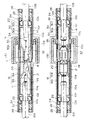
〔実施形態1〕 図1ないし図3は本発明の一実施形態を示す。図1はシールドコネクタ全体の垂直断面図(図6(A)に対応)である。図1において、シールド電線10A、10B、雄端子18及び雌端子32は従来と同じものである。また雄側及び雌側ハウジング16、30、雄側及び雌側シールドパイプ20、34、弾性リング22、固定リング24、ワイヤシールリング26、バックアップリング28及びハウジングシールリング36は、従来より径が若干大きくなっているが、基本的な構造は従来と同じである。
【0022】
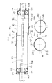
このシールドコネクタが従来と異なるのは、雄側シールドパイプ20と雌側シールドパイプ34の先端部の構造と、嵌合の仕方である。すなわち、雄側シールドパイプ20の先端部は、図2及び図3に示すように、雄端子18の両側に相当する位置にスロット38が形成され、上下に二分割されている。同様に雌側シールドパイプ34の先端部も、雌端子32の両側に相当する位置にスロット40が形成され、上下に二分割されている。そして、雄側シールドパイプ20の先端部下半分20bは雄側シールドパイプ20の基端側(外端側)と同径であるが、雄側シールドパイプ20の先端部上半分20aは先端部下半分20bより曲率半径が大きくなるように形成されている(図2(B)参照)。これとは反対に、雌側シールドパイプ34の先端部上半分34aは雌側シールドパイプ34の基端側(外端側)と同径であるが、雌側シールドパイプ34の先端部下半分34bは上半分34aより曲率半径が大きくなるように形成されている。なお雄側シールドパイプ20と雌側シールドパイプ34の先端部以外の部分は同径である。
【0023】
上記のように形成された雄側シールドパイプ20と雌側シールドパイプ34は、雄端子18と雌端子32が嵌合するときに、図2(A)に示すように、雄側シールドパイプ20の先端部上半分20aが雌側シールドパイプ34の先端部上半分34aの外側に、雄側シールドパイプ20の先端部下半分20bが雌側シールドパイプ34の先端部下半分34bの内側に位置した状態で嵌合するように、それぞれ雄側ハウジング16及び雌側ハウジング30に組み込まれる。つまり雄側シールドパイプ20と雌側シールドパイプ34は、中心軸線を上下に偏心させた状態で嵌合するようになるので、雄端子18と雌端子32の嵌合部中心軸線Vを両者の中心軸線の中間に位置させることにより、雄側シールドパイプ20の中心軸線Xを嵌合部中心軸線Vより上に偏心させ、雌側シールドパイプ34の中心軸線Yを嵌合部中心軸線Vより下に偏心させることが可能となる。このようにすれば雄コネクタ12及び雌コネクタ14内の絶縁心線(導体10pと絶縁被覆10qよりなる心線)の曲がりは解消ないし緩和されることになり、雄端子18及び雌コネクタ32を傾かせるような力が全くないし殆ど発生しなくなるので、信頼性の高い接続状態を得ることができる。
【0024】
〔実施形態2〕 図4は本発明の他の実施形態を示す。図4はシールドコネクタからシールド接続に関わる部品のみを抜き出して示した垂直断面図であるが、それ以外の構成は実施形態1と同じである。この実施形態では、雄側シールドパイプ20の先端部はスロット38により上下に二分割されているが、雌側シールドパイプ34の先端部は二分割されていない。雌側シールドパイプ34はストレート管の状態である。そして、雄側シールドパイプ20の先端部上半分20aは雌側シールドパイプ34の外側に接するように雌側シールドパイプ34の半径より大きい曲率半径に形成され、先端部下半分20bは雌側シールドパイプ34の内側に挿入できるように雌側シールドパイプ34の半径より小さい曲率半径に形成されている。なお雄側シールドパイプ20の基端側は雌側シールドパイプ34と同径である。
【0025】
このような構成でも、雄側シールドパイプ20と雌側シールドパイプ34を上下に偏心させた状態で嵌合させることができ、実施形態1と同様の効果を得ることができる。
【0026】
〔実施形態3〕 図5は本発明のさらに他の実施形態を示す。図5はシールドコネクタからシールド接続に関わる部品のみを抜き出して示した垂直断面図であるが、それ以外の構成は実施形態1と同じである。この実施形態では、雌側シールドパイプ34の先端部はスロット40により上下に二分割されているが、雄側シールドパイプ20の先端部は二分割されていない。雄側シールドパイプ20はストレート管の状態である。そして、雌側シールドパイプ34の先端部上半分34aは雄側シールドパイプ20の内側に挿入できるように雄側シールドパイプ20の半径より小さい曲率半径に形成され、先端部下半分34bは雄側シールドパイプ20の外側に接するように雄側シールドパイプ20の半径より大きい曲率半径に形成されている。なお雌側シールドパイプ34の基端側は雄側シールドパイプ20と同径である。
【0027】
このような構成でも、雄側シールドパイプ20と雌側シールドパイプ34を上下に偏心させた状態で先端部を嵌合させることができ、実施形態1と同様の効果を得ることができる。
【0028】
【発明の効果】
以上説明したように本発明によれば、雄端子と雌端子が嵌合したときに、雄側シールドパイプと雌側シールドパイプが後者より前者が上に偏心した状態で嵌合するようになっているので、雄コネクタ及び雌コネクタ内での雄端子と雌端子の構造の違いによる絶縁心線の曲がりを解消ないし緩和することができる。したがって雄端子及び雌コネクタを傾かせるような力が実質的に発生しなくなり、信頼性の高い接続状態を得ることができる。
【図面の簡単な説明】
【図1】 本発明に係るシールドコネクタの一実施形態を示す垂直断面図。
【図2】 図1のシールドコネクタからシールド接続に関わる部品だけを抜き出して示した垂直断面図。
【図3】 図1のシールドコネクタにおける雄側シールドパイプ及び雌側シールドパイプの外観を概略的に示す斜視図。
【図4】 本発明の他の実施形態を示す要部の垂直断面図。
【図5】 本発明のさらに他の実施形態を示す要部の垂直断面図。
【図6】 従来のシールドコネクタを示す、(A)は垂直断面図、(B)は水平断面図。
【図7】 図6のシールドコネクタからシールド接続に関わる部品だけを抜き出して示した垂直断面図。
【図8】 図6のシールドコネクタにおける雄側シールドパイプ及び雌側シールドパイプの外観を概略的に示す斜視図。
【符号の説明】
10A、10B:シールド電線
10p:導体
10q:絶縁被覆
10r:シールド編組
10s:シース
12:雄コネクタ
14:雌コネクタ
16:雄側ハウジング
18:雄端子
20:雄側シールドパイプ
20a:先端部上半分
20b:先端部下半分
22:弾性リング
24:固定リング
26:ワイヤシールリング
28:バックアップリング
30:雌側ハウジング
32:雌端子
34:雌側シールドパイプ
34a:先端部上半分
34b:先端部下半分
36:ハウジングシールリング
38、40:スロット[0001]
BACKGROUND OF THE INVENTION
The present invention relates to a shield connector used for connecting shielded wires.
[0002]
[Prior art]
A conventional shield connector is shown in FIG. (A) is a vertical sectional view, and (B) is a horizontal sectional view. The shield connector includes a
[0003]
The
[0004]
An
[0005]
A
[0006]
On the other hand, the
[0007]
The
[0008]
FIG. 7 is a vertical sectional view showing only the components related to the shield connection extracted from FIG. 6, and FIG. 8 is a perspective view showing the appearance of the
[0009]
[Problems to be solved by the invention]
As is clear from FIG. 6A, in the conventional shield connector, the insulation core wire (the
[0010]
This is due to the following reason. Since the
[0011]
Despite such structural differences, the
[0012]
When the insulating core wire is bent as described above, the reaction force of the force that bends the insulating core wire acts in a direction in which the postures of the
[0013]
In view of the above-described problems, an object of the present invention is to provide a shielded connector that improves the connection reliability by reducing the bending of the insulating core wire in the male connector and the female connector.
[0015]
[Means for Solving the Problems]
In order to achieve this object, the present invention
It consists of a male connector attached to the end of one shielded wire and a female connector attached to the end of the other shielded wire,
The male connector includes a male housing, a cylindrical male shield pipe coaxially disposed in the male housing, and a male terminal incorporated in the inner housing of the male housing within the male shield pipe. The shield part of the one shielded electric wire is coaxially arranged with the male shield pipe, the male terminal is crimped and connected to the central conductor of the shielded electric wire in the male shield pipe, and the male shield pipe is It is electrically connected to the shield conductor of the shield wire,
The female connector includes a female housing, a cylindrical female shield pipe coaxially disposed in the female housing, and a female terminal incorporated in the inner housing of the female housing in the female shield pipe. And the sheath portion of the other shielded electric wire is coaxially arranged with the female shield pipe, the female terminal is crimped to the central conductor of the shielded electric wire in the female shield pipe, and the female shield pipe is It is electrically connected to the shield conductor of the shield wire,
Both the male terminal and the female terminal have a flat terminal bottom surface, and the height from the terminal bottom surface to the conductor crimping portion central axis is the same, whereas the height from the bottom surface of the female terminal to the fitting portion central axis is the same. There made of a high casting than the height from the bottom surface of the male terminal to the fitting portion central axis,
When the male terminal and the female terminal are fitted together, in the shield connector in which the tip of the male shield pipe and the tip of the female shield pipe are fitted to each other,
The bottom side of the male and female terminals is defined as the bottom, and the side where the shielded wire central conductor on the opposite side is crimped is defined as the top. The male and female shield pipes are mated with the male and female terminals. The upper half of the tip of the male shield pipe is located outside the upper half of the tip of the female shield pipe, and the lower half of the tip of the male shield pipe is inside the lower half of the tip of the female shield pipe. Located, the center axis line of the male shield pipe and the center axis line of the female shield pipe are fitted in an eccentric state vertically,
The male connector mating part center axis of the male connector is eccentrically arranged below the male shield pipe center axis, and the female connector mating part center axis of the female connector is above the female shield pipe center axis. By providing eccentrically, the amount of eccentricity of the central axis of both shielded pipes is the amount of eccentricity due to the fitting of both shielded pipes,
Thereby, the bending of the insulation core wire connected to the male terminal and the female terminal is eliminated or alleviated.
[0016]
In this way, if the male shield pipe and the female shield pipe are fitted in an eccentric state, it is possible to eliminate or alleviate the bending of the insulation core wire in the male connector and the female connector. Become.
[0017]
More specifically, in the shield connector of the present invention, the distal end portion of the male shield pipe is divided into two vertically on both sides of the male terminal, and the distal end portion of the female shield pipe is divided into two vertically on both sides of the female terminal. The upper half of the tip of the male shield pipe has a larger radius of curvature than the upper half of the tip of the female shield pipe, and the lower half of the tip of the female shield pipe is larger than the lower half of the tip of the male shield pipe A configuration having a radius of curvature is preferable.
[0018]
In the shield connector of the present invention, only the tip of the male shield pipe is divided into two vertically on both sides of the male terminal, of the tip of the male shield pipe and the tip of the female shield pipe. The upper half of the tip of the shield pipe may have a larger radius of curvature than the tip of the female shield pipe, and the lower half of the tip of the male shield pipe may have a smaller radius of curvature than the tip of the female shield pipe. it can.
[0019]
In the shield connector of the present invention, only the tip of the female shield pipe of the tip of the male shield pipe and the tip of the female shield pipe is divided into two vertically on both sides of the female terminal. The upper half of the tip of the shield pipe may have a smaller radius of curvature than the tip of the male shield pipe, and the lower half of the tip of the female shield pipe may have a larger radius of curvature than the tip of the male shield pipe. it can.
[0020]
DETAILED DESCRIPTION OF THE INVENTION
Hereinafter, embodiments of the present invention will be described in detail with reference to the drawings.
[0021]
Embodiment 1 FIGS. 1 to 3 show an embodiment of the present invention. FIG. 1 is a vertical sectional view of the entire shielded connector (corresponding to FIG. 6A). In FIG. 1, the shielded
[0022]
This shield connector differs from the conventional one in the structure of the front end portions of the
[0023]
The
[0024]
Embodiment 2 FIG. 4 shows another embodiment of the present invention. FIG. 4 is a vertical cross-sectional view showing only the components related to the shield connection extracted from the shield connector, but the other configurations are the same as those of the first embodiment. In this embodiment, the distal end portion of the
[0025]
Even with such a configuration, the
[0026]
Embodiment 3 FIG. 5 shows still another embodiment of the present invention. FIG. 5 is a vertical sectional view showing only the components related to the shield connection extracted from the shield connector, but the other configurations are the same as those of the first embodiment. In this embodiment, the distal end portion of the
[0027]
Even in such a configuration, the tip end portion can be fitted in a state where the
[0028]
【The invention's effect】
As described above, according to the present invention, when the male terminal and the female terminal are fitted, the male side shield pipe and the female side shield pipe are fitted with the former being eccentric from the latter. Therefore, the bending of the insulation core wire due to the difference in structure between the male terminal and the female terminal in the male connector and the female connector can be eliminated or alleviated. Therefore, a force that tilts the male terminal and the female connector is substantially not generated, and a highly reliable connection state can be obtained.
[Brief description of the drawings]
FIG. 1 is a vertical sectional view showing an embodiment of a shielded connector according to the present invention.
2 is a vertical sectional view showing only components related to shield connection extracted from the shield connector of FIG. 1. FIG.
3 is a perspective view schematically showing the appearance of a male shield pipe and a female shield pipe in the shield connector of FIG. 1. FIG.
FIG. 4 is a vertical sectional view of an essential part showing another embodiment of the present invention.
FIG. 5 is a vertical sectional view of an essential part showing still another embodiment of the present invention.
6A and 6B show a conventional shield connector, in which FIG. 6A is a vertical sectional view and FIG. 6B is a horizontal sectional view.
7 is a vertical sectional view showing only the components related to the shield connection extracted from the shield connector of FIG. 6;
8 is a perspective view schematically showing the external appearance of a male shield pipe and a female shield pipe in the shield connector of FIG. 6. FIG.
[Explanation of symbols]
10A, 10B: shielded wire
10p: Conductor
10q: Insulation coating
10r: Shield braid
10s: sheath
12: Male connector
14: Female connector
16: Male housing
18: Male terminal
20: Male shield pipe
20a: Upper half of tip
20b: Lower half of the tip
22: Elastic ring
24: Retaining ring
26: Wire seal ring
28: Backup ring
30: Female housing
32: Female terminal
34: Female shield pipe
34a: Upper half of tip
34b: Lower half of the tip
36: Housing seal ring
38, 40: Slot
Claims (4)
前記雄コネクタ( 12 )は、雄側ハウジング( 16 )と、この雄側ハウジング( 16 )内に同軸配置された円筒状の雄側シールドパイプ( 20 )と、この雄側シールドパイプ( 20 )内で前記雄側ハウジング( 16 )のインナーハウジング( 16 a)に組み込まれた雄端子( 18 )とを有し、前記一方のシールド電線( 10 A)のシース( 10 s)部分は雄側シールドパイプ( 20 )と同軸配置され、前記雄端子( 18 )は雄側シールドパイプ( 20 )内で前記シールド電線( 10 A)の中心導体( 10 p)に圧着接続され、前記雄側シールドパイプ( 20 )は前記シールド電線( 10 A)のシールド導体( 10 r)と電気的に接続されており、
前記雌コネクタ( 14 )は、雌側ハウジング( 30 )と、この雌側ハウジング( 30 )内に同軸配置された円筒状の雌側シールドパイプ( 34 )と、この雌側シールドパイプ( 34 )内で前記雌側ハウジング( 30 )のインナーハウジング( 30 a)に組み込まれた雌端子( 32 )とを有し、前記他方のシールド電線( 10 B)のシース( 10 s)部分は雌側シールドパイプ( 34 )と同軸配置され、前記雌端子( 32 )は雌側シールドパイプ( 34 )内で前記シールド電線( 10 B)の中心導体( 10 p)に圧着接続され、前記雌側シールドパイプ( 34 )は前記シールド電線( 10 B)のシールド導体( 10 r)と電気的に接続されており、
前記雄端子(18)及び雌端子(32)は、両方とも端子底面が平坦で、端子底面から導体圧着部中心軸線(U)までの高さが同じであるのに対し、雌端子(32)の底面から嵌合部中心軸線(V)までの高さが雄端子(18)の底面から嵌合部中心軸線(V)までの高さより高いものからなり、
前記雄端子(18)と雌端子(32)を嵌合させると、雄側シールドパイプ(20)の先端部と雌側シールドパイプ(34)の先端部が互いに嵌合するようになっているシールドコネクタにおいて、
前記雄端子及び雌端子の底面側を下、その反対側のシールド電線中心導体を圧着する側を上と定義して、雄側シールドパイプ(20)と雌側シールドパイプ(34)は、雄端子と雌端子を嵌合させたときに、雄側シールドパイプの先端部上半分(20a)が雌側シールドパイプの先端部上半分(34a)の外側に位置し、雄側シールドパイプの先端部下半分(20b)が雌側シールドパイプの先端部下半分(34b)の内側に位置して、雄側シールドパイプ(20)の中心軸線(X)と雌側シールドパイプ(34)の中心軸線(Y)とが上下に偏心した状態で嵌合し、
雄コネクタ( 12 )の雄端子( 18 )の嵌合部中心軸線(V)を、雄側シールドパイプ( 20 )の中心軸線(X)より下に偏心して設け、雌コネクタ( 14 )の雌端子( 32 )の嵌合部中心軸線(V)を、雌側シールドパイプ( 34 )の中心軸線(Y)より上に偏心して設けることにより、両シールドパイプ( 20 、 34 )の中心軸線の前記偏心の量を、両シールドパイプ( 20 、 34 )が嵌合したことによる偏心量となるようにし、
これにより雄端子(18)及び雌端子(32)に接続された絶縁心線の曲がりを解消ないしは緩和するようになっていることを特徴とするシールドコネクタ。 It from the one of the shielded wire (10 A) a male connector attached to an end portion (12), the other of the shielded wire (10 B) a female connector attached to an end portion (14),
The male connector ( 12 ) includes a male housing ( 16 ), a cylindrical male shield pipe ( 20 ) arranged coaxially in the male housing ( 16 ), and a male shield pipe ( 20 ). in the and a male terminal incorporated in the inner housing (16 a) of the male housing (16) (18), the sheath (10 s) the portion of the one of the shielded wire (10 a) is a male-side shield pipe (20) and arranged coaxially, said male terminal (18) is connected by crimping to the central conductor (10 p) of the shielded electric wire in the male-side shield pipe (20) (10 a), the male-side shield pipe (20 ) is electrically connected to the shield conductor (10 r) of said shield wire (10 a),
The female connector ( 14 ) includes a female housing ( 30 ), a cylindrical female shield pipe ( 34 ) arranged coaxially in the female housing ( 30 ), and the female shield pipe ( 34 ). in the and a female terminal incorporated in the inner housing (30 a) of the female housing (30) (32), the sheath (10 s) the portion of the other of the shielded wire (10 B) is female shield pipe ( 34 ), and the female terminal ( 32 ) is crimped and connected to the central conductor ( 10 p) of the shielded electric wire ( 10 B) in the female shield pipe ( 34 ), and the female shield pipe ( 34 ) is electrically connected to the shield conductor (10 r) of said shield wire (10 B),
Both the male terminal (18) and the female terminal (32) have a flat terminal bottom surface, and the height from the terminal bottom surface to the conductor crimping portion central axis (U) is the same, whereas the female terminal (32) height from the bottom surface to the fitting portion central axis (V) is made of a high casting than the height from the bottom surface of the male terminal (18) to the fitting portion central axis (V),
A shield in which when the male terminal (18) and the female terminal (32) are fitted, the tip of the male shield pipe (20) and the tip of the female shield pipe (34) are fitted to each other. In the connector,
Under a bottom side of the male terminal and female terminal, the side crimping the shielded electric wire central conductor on the opposite side is defined as above, and the female-side shield pipe male-side shield pipe (20) (34), the male terminal The upper half (20a) of the male shield pipe is positioned outside the upper half (34a) of the female shield pipe when the female terminal and the female terminal are fitted, and the lower half of the male shield pipe. (20b) is positioned inside the lower half (34b) of the female shield pipe, and the central axis (X) of the male shield pipe (20) and the central axis (Y) of the female shield pipe (34) Is fitted in an eccentric state up and down,
Fitting portion center axis of the male terminals of the male connector (12) (18) to (V), provided eccentrically below the center axis (X) of the male-side shield pipe (20), the female terminal of the female connector (14) The center axis (V) of the fitting portion of ( 32 ) is eccentrically provided above the center axis (Y ) of the female shield pipe ( 34 ) so that the eccentricity of the center axis of both shield pipes ( 20 , 34 ) To be the amount of eccentricity due to the fitting of both shielded pipes ( 20 , 34 ),
As a result, the shield connector is characterized in that the bending of the insulation core wire connected to the male terminal (18) and the female terminal (32) is eliminated or alleviated.
Priority Applications (3)
| Application Number | Priority Date | Filing Date | Title |
|---|---|---|---|
| JP2001203354A JP4158877B2 (en) | 2001-07-04 | 2001-07-04 | Shield connector |
| EP02012433A EP1274154A3 (en) | 2001-07-04 | 2002-06-10 | Shield connector |
| US10/187,085 US6749464B2 (en) | 2001-07-04 | 2002-06-28 | Shield connector including male connector and female connector |
Applications Claiming Priority (1)
| Application Number | Priority Date | Filing Date | Title |
|---|---|---|---|
| JP2001203354A JP4158877B2 (en) | 2001-07-04 | 2001-07-04 | Shield connector |
Publications (2)
| Publication Number | Publication Date |
|---|---|
| JP2003017191A JP2003017191A (en) | 2003-01-17 |
| JP4158877B2 true JP4158877B2 (en) | 2008-10-01 |
Family
ID=19040008
Family Applications (1)
| Application Number | Title | Priority Date | Filing Date |
|---|---|---|---|
| JP2001203354A Expired - Lifetime JP4158877B2 (en) | 2001-07-04 | 2001-07-04 | Shield connector |
Country Status (3)
| Country | Link |
|---|---|
| US (1) | US6749464B2 (en) |
| EP (1) | EP1274154A3 (en) |
| JP (1) | JP4158877B2 (en) |
Families Citing this family (30)
| Publication number | Priority date | Publication date | Assignee | Title |
|---|---|---|---|---|
| JP4199597B2 (en) * | 2003-05-30 | 2008-12-17 | 日本圧着端子製造株式会社 | Connector for antenna |
| JP2005108510A (en) * | 2003-09-29 | 2005-04-21 | Clarion Co Ltd | Multi-pole type high frequency coaxial connector |
| DE102004051367A1 (en) * | 2003-10-23 | 2005-06-09 | AUTONETWORKS Technologies, LTD., Yokkaichi | Shielded connector for wire bundle, has outer cylindrical portion of rubber plug holder, that protects resin coating from interference with shield shell when coating is bend such that wires are diverted away from normal wiring path |
| US7004793B2 (en) * | 2004-04-28 | 2006-02-28 | 3M Innovative Properties Company | Low inductance shielded connector |
| US7204716B1 (en) * | 2006-03-01 | 2007-04-17 | Delphi Technologies, Inc. | Shielded electrical connector and connection system |
| US7351098B2 (en) * | 2006-04-13 | 2008-04-01 | Delphi Technologies, Inc. | EMI shielded electrical connector and connection system |
| JP4821573B2 (en) * | 2006-11-20 | 2011-11-24 | 住友電装株式会社 | Shield connector |
| US7726985B2 (en) * | 2007-02-20 | 2010-06-01 | Delphi Technologies, Inc. | Shielded electric cable assembly and method |
| US7598455B2 (en) * | 2007-03-01 | 2009-10-06 | Delphi Technologies, Inc. | Shielded electric cable assembly and method |
| WO2008109109A1 (en) * | 2007-03-06 | 2008-09-12 | Tyco Electronics Corporation | High voltage shielded electrical connector assembly |
| JP5186170B2 (en) * | 2007-10-05 | 2013-04-17 | 矢崎総業株式会社 | Conductive member and connector having the conductive member |
| US7868251B2 (en) * | 2008-04-08 | 2011-01-11 | Delphi Technologies, Inc. | Shielded electric cable assembly |
| JP4820421B2 (en) * | 2009-01-13 | 2011-11-24 | ホシデン株式会社 | connector |
| KR101667745B1 (en) * | 2009-04-20 | 2016-10-19 | 에이에스엠엘 네델란즈 비.브이. | Lithographic projection apparatus and device manufacturing method |
| JP5339154B2 (en) * | 2010-01-14 | 2013-11-13 | 住友電装株式会社 | Shield connector |
| JP5293628B2 (en) * | 2010-02-01 | 2013-09-18 | 日立電線株式会社 | connector |
| JP5730132B2 (en) | 2011-06-03 | 2015-06-03 | 矢崎総業株式会社 | Connector unit |
| JP6002592B2 (en) | 2013-02-04 | 2016-10-05 | 矢崎総業株式会社 | Electric wire terminal connection structure |
| US8979592B2 (en) * | 2013-03-15 | 2015-03-17 | Carlisle Interconnect Technologies, Inc. | Electrical connector for high-speed data transmission |
| US9106025B2 (en) | 2013-07-09 | 2015-08-11 | Coninvers Gmbh | Shielded circular plug connector unit with symmetrically arranged plug contacts |
| DK2824775T3 (en) * | 2013-07-09 | 2019-02-04 | Phoenix Contact Connector Tech Gmbh | SHIELDED SOCKET WITH SYMMETRIC LOCATED CONNECTOR |
| JP2016157642A (en) * | 2015-02-25 | 2016-09-01 | アルプス電気株式会社 | Shield connection structure |
| US9577362B1 (en) * | 2015-11-10 | 2017-02-21 | Amphenol Corporation | Electrical connector assembly |
| JP6750525B2 (en) * | 2017-02-02 | 2020-09-02 | 株式会社オートネットワーク技術研究所 | Shield connector and male shield terminal |
| US10858022B2 (en) * | 2018-07-17 | 2020-12-08 | Ridge Tool Company | Separable transport carts for sectional drain cleaner |
| US10923863B2 (en) | 2018-12-04 | 2021-02-16 | J.S.T. Corporation | High voltage connector and method for assembling thereof |
| US10923860B2 (en) * | 2019-02-25 | 2021-02-16 | J.S.T. Corporation | Method for shielding and grounding a connector assembly from electromagnetic interference (EMI) using conductive seal and conductive housing |
| US10804655B2 (en) | 2019-02-28 | 2020-10-13 | J.S.T. Corporation | Method for electromagnetic interference (EMI) protection for a connector assembly using a conductive seal |
| DE102020204913A1 (en) * | 2020-04-17 | 2021-10-21 | Te Connectivity Germany Gmbh | Miniaturized connector |
| US11735858B2 (en) * | 2020-07-14 | 2023-08-22 | J.S.T. Corporation | Elastomer seal spring |
Family Cites Families (3)
| Publication number | Priority date | Publication date | Assignee | Title |
|---|---|---|---|---|
| US3958851A (en) * | 1974-12-30 | 1976-05-25 | Ibm Corporation | Shielded connector |
| US4192566A (en) * | 1978-12-26 | 1980-03-11 | Amp Incorporated | Antenna lead splice |
| JP3585061B2 (en) * | 1995-06-06 | 2004-11-04 | 矢崎総業株式会社 | Shield connector |
-
2001
- 2001-07-04 JP JP2001203354A patent/JP4158877B2/en not_active Expired - Lifetime
-
2002
- 2002-06-10 EP EP02012433A patent/EP1274154A3/en not_active Withdrawn
- 2002-06-28 US US10/187,085 patent/US6749464B2/en not_active Expired - Fee Related
Also Published As
| Publication number | Publication date |
|---|---|
| JP2003017191A (en) | 2003-01-17 |
| EP1274154A3 (en) | 2007-09-12 |
| EP1274154A2 (en) | 2003-01-08 |
| US20030008555A1 (en) | 2003-01-09 |
| US6749464B2 (en) | 2004-06-15 |
Similar Documents
| Publication | Publication Date | Title |
|---|---|---|
| JP4158877B2 (en) | Shield connector | |
| JP2000323233A (en) | Connector device | |
| JP4663636B2 (en) | Female terminal with flexible side wall and flat inclined contact | |
| JP2644548B2 (en) | Electrical connector | |
| US6811450B1 (en) | Electrical receptacle-type terminal | |
| KR20190108069A (en) | Connection terminal | |
| JP3066589B2 (en) | Shielded electrical connector assembly with grounding mechanism | |
| US5885104A (en) | Electrical plug connector | |
| WO2006044770A1 (en) | Cable connector with termination arrangement | |
| JPH10106663A (en) | Electric terminal | |
| TWI831388B (en) | Electrical connector, manufacturing method and connector assembly | |
| JP3186021B2 (en) | Connector for coaxial cable and method of manufacturing the same | |
| JP2023018173A (en) | connector | |
| JP3204887B2 (en) | Female terminal of connector for electrical connection | |
| JP3307877B2 (en) | Electrical contacts | |
| CN110797691A (en) | Flexible circuit socket, plug and connector assembly | |
| JPH0559773U (en) | Coaxial cable connector | |
| CN216903446U (en) | Electric connector combination | |
| CN219801314U (en) | Male base of board-to-board connector and connector combination | |
| CN210123812U (en) | Electrical connector assembly | |
| KR200273020Y1 (en) | Wire splice assembly | |
| CN216529482U (en) | Coaxial cable connector | |
| JP2024077927A (en) | Crimp-style terminal and electric wire with terminal | |
| JP2024100334A (en) | Terminal fittings and wires with terminals | |
| JP2001189168A (en) | Clmping structure for electric connection terminal |
Legal Events
| Date | Code | Title | Description |
|---|---|---|---|
| A977 | Report on retrieval |
Free format text: JAPANESE INTERMEDIATE CODE: A971007 Effective date: 20040705 |
|
| A131 | Notification of reasons for refusal |
Free format text: JAPANESE INTERMEDIATE CODE: A131 Effective date: 20040727 |
|
| A521 | Written amendment |
Free format text: JAPANESE INTERMEDIATE CODE: A523 Effective date: 20040921 |
|
| A02 | Decision of refusal |
Free format text: JAPANESE INTERMEDIATE CODE: A02 Effective date: 20050627 |
|
| A521 | Written amendment |
Free format text: JAPANESE INTERMEDIATE CODE: A523 Effective date: 20050823 |
|
| A911 | Transfer to examiner for re-examination before appeal (zenchi) |
Free format text: JAPANESE INTERMEDIATE CODE: A911 Effective date: 20050926 |
|
| A912 | Re-examination (zenchi) completed and case transferred to appeal board |
Free format text: JAPANESE INTERMEDIATE CODE: A912 Effective date: 20061006 |
|
| A521 | Written amendment |
Free format text: JAPANESE INTERMEDIATE CODE: A523 Effective date: 20080529 |
|
| A01 | Written decision to grant a patent or to grant a registration (utility model) |
Free format text: JAPANESE INTERMEDIATE CODE: A01 |
|
| A61 | First payment of annual fees (during grant procedure) |
Free format text: JAPANESE INTERMEDIATE CODE: A61 Effective date: 20080709 |
|
| R151 | Written notification of patent or utility model registration |
Ref document number: 4158877 Country of ref document: JP Free format text: JAPANESE INTERMEDIATE CODE: R151 |
|
| FPAY | Renewal fee payment (event date is renewal date of database) |
Free format text: PAYMENT UNTIL: 20110725 Year of fee payment: 3 |
|
| FPAY | Renewal fee payment (event date is renewal date of database) |
Free format text: PAYMENT UNTIL: 20110725 Year of fee payment: 3 |
|
| FPAY | Renewal fee payment (event date is renewal date of database) |
Free format text: PAYMENT UNTIL: 20120725 Year of fee payment: 4 |
|
| R250 | Receipt of annual fees |
Free format text: JAPANESE INTERMEDIATE CODE: R250 |
|
| FPAY | Renewal fee payment (event date is renewal date of database) |
Free format text: PAYMENT UNTIL: 20120725 Year of fee payment: 4 |
|
| FPAY | Renewal fee payment (event date is renewal date of database) |
Free format text: PAYMENT UNTIL: 20130725 Year of fee payment: 5 |
|
| R250 | Receipt of annual fees |
Free format text: JAPANESE INTERMEDIATE CODE: R250 |
|
| EXPY | Cancellation because of completion of term |