WO2018207271A1 - Light quantity adjustment device, image pickup device, image pickup system, and mobile body - Google Patents
Light quantity adjustment device, image pickup device, image pickup system, and mobile body Download PDFInfo
- Publication number
- WO2018207271A1 WO2018207271A1 PCT/JP2017/017608 JP2017017608W WO2018207271A1 WO 2018207271 A1 WO2018207271 A1 WO 2018207271A1 JP 2017017608 W JP2017017608 W JP 2017017608W WO 2018207271 A1 WO2018207271 A1 WO 2018207271A1
- Authority
- WO
- WIPO (PCT)
- Prior art keywords
- rotating member
- light amount
- base member
- amount adjusting
- adjusting device
- Prior art date
Links
- 230000003746 surface roughness Effects 0.000 claims abstract description 10
- 238000003384 imaging method Methods 0.000 claims description 59
- 230000005484 gravity Effects 0.000 claims description 30
- 230000007246 mechanism Effects 0.000 claims description 5
- 230000002093 peripheral effect Effects 0.000 claims description 4
- 238000000034 method Methods 0.000 description 6
- 230000008569 process Effects 0.000 description 4
- 238000010586 diagram Methods 0.000 description 3
- 230000006870 function Effects 0.000 description 3
- 238000003491 array Methods 0.000 description 2
- 230000003287 optical effect Effects 0.000 description 2
- 230000004044 response Effects 0.000 description 2
- 230000001174 ascending effect Effects 0.000 description 1
- 230000008859 change Effects 0.000 description 1
- 230000008602 contraction Effects 0.000 description 1
- 230000001419 dependent effect Effects 0.000 description 1
- 235000013372 meat Nutrition 0.000 description 1
- 230000004048 modification Effects 0.000 description 1
- 238000012986 modification Methods 0.000 description 1
- 238000007788 roughening Methods 0.000 description 1
- 239000004065 semiconductor Substances 0.000 description 1
- 230000003068 static effect Effects 0.000 description 1
- 230000008719 thickening Effects 0.000 description 1
- XLYOFNOQVPJJNP-UHFFFAOYSA-N water Substances O XLYOFNOQVPJJNP-UHFFFAOYSA-N 0.000 description 1
Images


Classifications
-
- F—MECHANICAL ENGINEERING; LIGHTING; HEATING; WEAPONS; BLASTING
- F21—LIGHTING
- F21V—FUNCTIONAL FEATURES OR DETAILS OF LIGHTING DEVICES OR SYSTEMS THEREOF; STRUCTURAL COMBINATIONS OF LIGHTING DEVICES WITH OTHER ARTICLES, NOT OTHERWISE PROVIDED FOR
- F21V14/00—Controlling the distribution of the light emitted by adjustment of elements
- F21V14/08—Controlling the distribution of the light emitted by adjustment of elements by movement of the screens or filters
-
- H—ELECTRICITY
- H04—ELECTRIC COMMUNICATION TECHNIQUE
- H04N—PICTORIAL COMMUNICATION, e.g. TELEVISION
- H04N23/00—Cameras or camera modules comprising electronic image sensors; Control thereof
-
- B—PERFORMING OPERATIONS; TRANSPORTING
- B64—AIRCRAFT; AVIATION; COSMONAUTICS
- B64C—AEROPLANES; HELICOPTERS
- B64C39/00—Aircraft not otherwise provided for
- B64C39/02—Aircraft not otherwise provided for characterised by special use
- B64C39/024—Aircraft not otherwise provided for characterised by special use of the remote controlled vehicle type, i.e. RPV
-
- F—MECHANICAL ENGINEERING; LIGHTING; HEATING; WEAPONS; BLASTING
- F21—LIGHTING
- F21S—NON-PORTABLE LIGHTING DEVICES; SYSTEMS THEREOF; VEHICLE LIGHTING DEVICES SPECIALLY ADAPTED FOR VEHICLE EXTERIORS
- F21S41/00—Illuminating devices specially adapted for vehicle exteriors, e.g. headlamps
- F21S41/60—Illuminating devices specially adapted for vehicle exteriors, e.g. headlamps characterised by a variable light distribution
- F21S41/68—Illuminating devices specially adapted for vehicle exteriors, e.g. headlamps characterised by a variable light distribution by acting on screens
- F21S41/683—Illuminating devices specially adapted for vehicle exteriors, e.g. headlamps characterised by a variable light distribution by acting on screens by moving screens
- F21S41/695—Screens rotating around a vertical axis
-
- F—MECHANICAL ENGINEERING; LIGHTING; HEATING; WEAPONS; BLASTING
- F21—LIGHTING
- F21V—FUNCTIONAL FEATURES OR DETAILS OF LIGHTING DEVICES OR SYSTEMS THEREOF; STRUCTURAL COMBINATIONS OF LIGHTING DEVICES WITH OTHER ARTICLES, NOT OTHERWISE PROVIDED FOR
- F21V11/00—Screens not covered by groups F21V1/00, F21V3/00, F21V7/00 or F21V9/00
- F21V11/08—Screens not covered by groups F21V1/00, F21V3/00, F21V7/00 or F21V9/00 using diaphragms containing one or more apertures
- F21V11/10—Screens not covered by groups F21V1/00, F21V3/00, F21V7/00 or F21V9/00 using diaphragms containing one or more apertures of iris type
-
- G—PHYSICS
- G03—PHOTOGRAPHY; CINEMATOGRAPHY; ANALOGOUS TECHNIQUES USING WAVES OTHER THAN OPTICAL WAVES; ELECTROGRAPHY; HOLOGRAPHY
- G03B—APPARATUS OR ARRANGEMENTS FOR TAKING PHOTOGRAPHS OR FOR PROJECTING OR VIEWING THEM; APPARATUS OR ARRANGEMENTS EMPLOYING ANALOGOUS TECHNIQUES USING WAVES OTHER THAN OPTICAL WAVES; ACCESSORIES THEREFOR
- G03B15/00—Special procedures for taking photographs; Apparatus therefor
-
- G—PHYSICS
- G03—PHOTOGRAPHY; CINEMATOGRAPHY; ANALOGOUS TECHNIQUES USING WAVES OTHER THAN OPTICAL WAVES; ELECTROGRAPHY; HOLOGRAPHY
- G03B—APPARATUS OR ARRANGEMENTS FOR TAKING PHOTOGRAPHS OR FOR PROJECTING OR VIEWING THEM; APPARATUS OR ARRANGEMENTS EMPLOYING ANALOGOUS TECHNIQUES USING WAVES OTHER THAN OPTICAL WAVES; ACCESSORIES THEREFOR
- G03B9/00—Exposure-making shutters; Diaphragms
- G03B9/02—Diaphragms
- G03B9/06—Two or more co-operating pivoted blades, e.g. iris type
-
- H—ELECTRICITY
- H04—ELECTRIC COMMUNICATION TECHNIQUE
- H04N—PICTORIAL COMMUNICATION, e.g. TELEVISION
- H04N5/00—Details of television systems
- H04N5/222—Studio circuitry; Studio devices; Studio equipment
-
- B—PERFORMING OPERATIONS; TRANSPORTING
- B64—AIRCRAFT; AVIATION; COSMONAUTICS
- B64U—UNMANNED AERIAL VEHICLES [UAV]; EQUIPMENT THEREFOR
- B64U10/00—Type of UAV
- B64U10/10—Rotorcrafts
- B64U10/13—Flying platforms
-
- B—PERFORMING OPERATIONS; TRANSPORTING
- B64—AIRCRAFT; AVIATION; COSMONAUTICS
- B64U—UNMANNED AERIAL VEHICLES [UAV]; EQUIPMENT THEREFOR
- B64U20/00—Constructional aspects of UAVs
- B64U20/80—Arrangement of on-board electronics, e.g. avionics systems or wiring
- B64U20/87—Mounting of imaging devices, e.g. mounting of gimbals
-
- B—PERFORMING OPERATIONS; TRANSPORTING
- B64—AIRCRAFT; AVIATION; COSMONAUTICS
- B64U—UNMANNED AERIAL VEHICLES [UAV]; EQUIPMENT THEREFOR
- B64U2101/00—UAVs specially adapted for particular uses or applications
- B64U2101/30—UAVs specially adapted for particular uses or applications for imaging, photography or videography
-
- B—PERFORMING OPERATIONS; TRANSPORTING
- B64—AIRCRAFT; AVIATION; COSMONAUTICS
- B64U—UNMANNED AERIAL VEHICLES [UAV]; EQUIPMENT THEREFOR
- B64U2201/00—UAVs characterised by their flight controls
- B64U2201/20—Remote controls
Definitions
- the present invention relates to a light amount adjustment device, an imaging device, an imaging system, and a moving body.
- Patent Document 1 Japanese Patent Application Laid-Open No. 2012-145929
- a member that adjusts the amount of light such as a diaphragm provided in the imaging apparatus may move due to an impact, and the amount of light may not be controlled appropriately.
- the light amount adjusting device may include a rotating member.
- the light amount adjusting device may include a light amount adjusting member that is engaged with the rotating member, is driven by rotation of the rotating member, and adjusts the amount of light to be transmitted.
- the rotating member may have a main body portion.
- the rotating member may include a gear portion that is provided in the main body portion and receives power from the drive source.
- the rotating member may have a weight portion provided in the main body portion. The position of the combined center of gravity of the main body portion, the gear portion, and the weight portion may be closer to the rotation axis of the rotating member than the position of the main body portion, the gear portion, and the combined center of gravity.
- the distance between the line obtained by projecting the vertical line passing through the center of gravity of the rotating member onto the plane perpendicular to the rotating axis of the rotating member and the intersection of the plane and the rotating axis of the rotating member is It may be shorter than the distance between the line obtained by projecting the horizontal line passing through the center of gravity onto the plane and the intersection.
- the position of the center of gravity of the rotating member may be on the rotating shaft of the rotating member.
- the gear portion may have a meat removal portion.
- the light amount adjusting device may further include a base member.
- the rotating member may be held rotatably with respect to the base member.
- the surface roughness of the first surface region of the rotating member that contacts the base member may be greater than the surface roughness of the second surface region of the rotating member that does not contact the base member.
- the rotating member may be plate-shaped.
- the rotating member may be provided between the base member and the light amount adjusting member.
- the first surface region of the rotating member may be included in a surface facing the base member.
- the rotating member may be plate-shaped.
- the rotating member may be provided between the base member and the light amount adjusting member.
- the second surface region of the rotating member may be included in a surface facing the light amount adjusting member.
- the base member may have a convex portion on which the rotating member is rotatably fitted.
- the rotating member may be plate-shaped.
- the rotating member may be rotatably fitted to the convex portion of the base member.
- the first surface region of the rotating member may be included in a surface facing the convex portion of the base member.
- the light amount adjusting device may include an elastic member that biases the rotating member.
- the elastic member may press the first surface region of the rotating member against the base member.
- the base member may have a recess that rotatably accommodates the rotating member.
- the elastic member may be provided between the side wall of the recess and the side surface of the rotating member facing the side wall of the recess.
- the base member may have a holding part that holds the rotating member in a rotatable manner.
- the elastic member may be provided between the holding portion and the rotating member.
- the rotating member may be provided between the base member and the light amount adjusting member.
- the rotating member may be a plate-like annular member having an opening.
- the base member may include a recess that rotatably accommodates the rotating member.
- the base member may be provided in the concave portion and may have a convex portion protruding from the bottom surface of the concave portion so as to be rotatably fitted in the opening portion.
- the first surface region of the rotating member may be included in a surface facing the convex portion of the base member.
- the elastic member may be provided between the side wall of the recess and the outer peripheral side surface of the rotating member facing the side wall of the recess.
- the rotating member may be provided between the base member and the light amount adjusting member.
- the rotating member may be a plate-like annular member having an opening.
- the base member may include a recess that rotatably accommodates the rotating member.
- the base member may be provided in the concave portion and may have a convex portion protruding from the bottom surface of the concave portion so as to be rotatably fitted in the opening portion.
- the base member may include a holding portion that is provided on the convex portion and holds the rotating member so as to be rotatable.
- the first surface region of the rotating member may be included in a surface facing the base member.
- the elastic member may be provided between the holding portion and the rotating member.
- the light quantity adjustment member may be a diaphragm including a plurality of diaphragm blades.
- An imaging device may include the light amount adjustment device.
- the imaging device may include an image sensor that forms an image of light that has passed through the light amount adjustment device.
- An imaging system may include the imaging device.
- the imaging system may include a support mechanism that supports the imaging device.
- a moving body according to one embodiment of the present invention moves with the imaging system.
- FIG. 13 is an enlarged view of the vicinity of the holding portion of the cross section taken along line AA of FIG.
- a block is either (1) a stage in a process in which an operation is performed or (2) an apparatus responsible for performing the operation. May represent a “part”.
- Certain stages and “units” may be implemented by programmable circuits and / or processors.
- Dedicated circuitry may include digital and / or analog hardware circuitry.
- Integrated circuits (ICs) and / or discrete circuits may be included.
- the programmable circuit may include a reconfigurable hardware circuit.
- Reconfigurable hardware circuits include logical AND, logical OR, logical XOR, logical NAND, logical NOR, and other logical operations, flip-flops, registers, field programmable gate arrays (FPGA), programmable logic arrays (PLA), etc.
- the memory element or the like may be included.
- the computer readable medium may include any tangible device capable of storing instructions to be executed by a suitable device.
- a computer readable medium having instructions stored thereon comprises a product that includes instructions that can be executed to create a means for performing the operations specified in the flowcharts or block diagrams.
- Examples of computer readable media may include electronic storage media, magnetic storage media, optical storage media, electromagnetic storage media, semiconductor storage media, and the like.
- Computer readable media include floppy disks, diskettes, hard disks, random access memory (RAM), read only memory (ROM), erasable programmable read only memory (EPROM or flash memory), Electrically erasable programmable read only memory (EEPROM), static random access memory (SRAM), compact disc read only memory (CD-ROM), digital versatile disc (DVD), Blu-ray (RTM) disc, memory stick, integrated A circuit card or the like may be included.
- RAM random access memory
- ROM read only memory
- EPROM or flash memory erasable programmable read only memory
- EEPROM Electrically erasable programmable read only memory
- SRAM static random access memory
- CD-ROM compact disc read only memory
- DVD digital versatile disc
- RTM Blu-ray
- the computer readable instructions may include either source code or object code written in any combination of one or more programming languages.
- the source code or object code includes a conventional procedural programming language.
- Conventional procedural programming languages include assembler instructions, instruction set architecture (ISA) instructions, machine instructions, machine dependent instructions, microcode, firmware instructions, state setting data, or Smalltalk, JAVA, C ++, etc. It may be an object-oriented programming language and a “C” programming language or a similar programming language.
- Computer readable instructions may be directed to a general purpose computer, special purpose computer, or other programmable data processing device processor or programmable circuit locally or in a wide area network (WAN) such as a local area network (LAN), the Internet, etc. ).
- WAN wide area network
- LAN local area network
- the Internet etc.
- the processor or programmable circuit may execute computer readable instructions to create a means for performing the operations specified in the flowcharts or block diagrams.
- Examples of processors include computer processors, processing units, microprocessors, digital signal processors, controllers, microcontrollers, and the like.
- FIG. 1 shows an example of the external appearance of an unmanned aerial vehicle (UAV) 10 and a remote control device 300.
- the UAV 10 includes a UAV main body 20, a gimbal 50, a plurality of imaging devices 60, and an imaging device 100.
- the gimbal 50 and the imaging device 100 are an example of an imaging system.
- the UAV 10 is an example of a moving body propelled by a propulsion unit.
- the moving body is a concept including a flying body such as another aircraft moving in the air, a vehicle moving on the ground, a ship moving on the water, etc. in addition to the UAV.
- the UAV main body 20 includes a plurality of rotor blades.
- the plurality of rotor blades is an example of a propulsion unit.
- the UAV main body 20 causes the UAV 10 to fly by controlling the rotation of a plurality of rotor blades.
- the UAV main body 20 causes the UAV 10 to fly using four rotary wings.
- the number of rotor blades is not limited to four.
- the UAV 10 may be a fixed wing machine that does not have a rotating wing.
- the imaging apparatus 100 is an imaging camera that images a subject included in a desired imaging range.
- the gimbal 50 supports the imaging device 100 so that the posture of the imaging device 100 can be changed.
- the gimbal 50 supports the imaging device 100 in a rotatable manner.
- the gimbal 50 is an example of a support mechanism.
- the gimbal 50 supports the imaging device 100 so as to be rotatable about the pitch axis using an actuator.
- the gimbal 50 further supports the imaging apparatus 100 using an actuator so as to be rotatable about the roll axis and the yaw axis.
- the gimbal 50 may change the posture of the imaging device 100 by rotating the imaging device 100 about at least one of the yaw axis, the pitch axis, and the roll axis.
- the plurality of imaging devices 60 are sensing cameras that image the surroundings of the UAV 10 in order to control the flight of the UAV 10.
- Two imaging devices 60 may be provided in the front which is the nose of UAV10.
- Two other imaging devices 60 may be provided on the bottom surface of the UAV 10.
- the two imaging devices 60 on the front side may be paired and function as a so-called stereo camera.
- the two imaging devices 60 on the bottom side may also be paired and function as a stereo camera. Based on images picked up by a plurality of image pickup devices 60, three-dimensional spatial data around the UAV 10 may be generated.
- the number of imaging devices 60 included in the UAV 10 is not limited to four.
- the UAV 10 only needs to include at least one imaging device 60.
- the UAV 10 may include at least one imaging device 60 on each of the nose, the tail, the side surface, the bottom surface, and the ceiling surface of the UAV 10.
- the angle of view that can be set by the imaging device 60 may be wider than the angle of view that can be set by the imaging device 100. That is, the imaging range of the imaging device 60 may be wider than the imaging range of the imaging device 100.
- the imaging device 60 may have a single focus lens or a fisheye lens.
- the remote operation device 300 communicates with the UAV 10 to remotely operate the UAV 10.
- the remote operation device 300 may communicate with the UAV 10 wirelessly.
- the remote operation device 300 transmits drive information indicating various drive commands relating to movement of the UAV 10 such as ascending, descending, accelerating, decelerating, moving forward, backward, and rotating to the UAV 10.
- the drive information includes, for example, drive information for raising the altitude of the UAV 10.
- the drive information may indicate the altitude at which the UAV 10 should be located.
- the UAV 10 moves so as to be located at an altitude indicated by the drive information received from the remote control device 300.
- FIG. 2 is an example of an external perspective view of the imaging apparatus 100.
- the imaging apparatus 100 may receive a relatively large impact depending on the environment in which it is used. For example, the imaging device 100 mounted on the UAV 10 is likely to receive a relatively large impact when the UAV 10 is landed. Due to such an impact, a member included in the light amount adjusting device that adjusts the amount of light such as a diaphragm included in the imaging device 100 may move, and the amount of light may not be adjusted appropriately.
- FIG. 3 shows an example of an exploded perspective view of the light amount adjusting device 200.
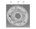
- FIG. 4 shows an example of an external perspective view of the light amount adjustment device 200 with the cover 240 removed.
- the light amount adjustment device 200 may be provided in the imaging device 100.
- the light amount adjustment device 200 may be provided in the imaging device 60.
- the light amount adjusting device 200 includes a base member 210, a rotating member 220, a diaphragm unit 230, a cover 240, and a stepping motor 250.
- the rotating member 220 is held rotatably with respect to the base member 210.
- the rotating member 220 is provided between the base member 210 and the throttle unit 230.
- the rotating member 220 is a plate-like annular member having an opening 222.
- the rotating member 220 includes an annular main body portion 221 and a gear portion 224 that receives power from the stepping motor 250.
- the base member 210 has a recess 212 that rotatably accommodates the rotating member 220.
- the base member 210 has a convex portion 214 to which the rotating member 220 is rotatably fitted.
- the convex portion 214 is provided in the concave portion 212 and protrudes from the bottom surface of the concave portion 212 so as to be rotatably fitted in the opening 222 of the rotating member 220.
- the convex portion 214 has an opening 218 through which light passes in the central portion.
- the diaphragm unit 230 is engaged with the rotating member 220 and is driven by the rotation of the rotating member 220 in response to the power from the stepping motor 250 to adjust the amount of light passing therethrough.
- the diaphragm unit 230 is an example of a light amount adjusting member.
- the diaphragm unit 230 has a plurality of diaphragm blades 232.
- the aperture blade 232 has a through hole 233 and a guide groove 234. By inserting the support pin 216 provided on the base member 210 into the through hole 233, the aperture blade 232 is rotatably supported by the base member 210. Guide pins 2221 provided on the rotating member 220 are guided by the guide grooves 234.
- a diaphragm opening 235 is formed by the inner edge of each of the plurality of diaphragm blades 232 in a state where the plurality of diaphragm blades 232 overlap each other.
- the guide pin 2221 moves along the guide groove 234 in response to the rotation of the rotating member 220 receiving power from the stepping motor 250. Thereby, the aperture blade 232 rotates around the through hole 233, and the size of the aperture opening 235 changes.
- the cover 240 is fixed to the base member 210 in a state where the rotating member 220 and the throttle portion 230 are sandwiched between the cover 240 and the base member 210.
- the cover 240 has a through hole 243.
- the base member 210 has a fixing pin 217.
- the through hole 243 is inserted into the fixing pin 217, and the cover 240 is positioned and fixed with respect to the base member 210.
- the stepping motor 250 has a gear portion 252 on the drive shaft.
- the stepping motor 250 is held by the base member 210.
- the gear portion 224 of the rotating member 220 is engaged with the gear portion 252 and the stepping motor 250 is driven to rotate the rotating member 220.
- the stepping motor 250 is kept in an energized state so that the rotating member 220 does not rotate due to an impact or the like.
- electric power is required to keep the stepping motor 250 energized.
- the imaging apparatus 100 is used in an environment that is susceptible to a relatively large impact such as the UAV 10, a relatively large amount of electric power is continuously supplied to the stepping motor 250 in order to prevent the rotating member 220 from moving due to the impact. It may be necessary.
- the rotating member 220 is prevented from rotating due to an impact while suppressing power consumption.
- the rotating member 220 includes the gear portion 224 in addition to the main body portion 221.
- the rotating member 220 further includes a weight portion 226 provided in the main body portion 221.
- the weight part 226 may be provided in consideration of the weight of the gear part 224.
- the weight part 226 may be provided at a position facing the gear part 224 across the opening 222.
- the weight portion 226 may have the same weight as the gear portion 224.
- the center of gravity of the rotating member 220 is brought close to the rotating shaft of the rotating member 220.
- the position of the combined center of gravity of the main body part 221, the gear part 224, and the weight part 226 is closer to the rotational axis of the rotating member 220 than the position of the combined center of gravity of the main body part 221 and the gear part 224.
- the position of the center of gravity of the rotation member 220 may be on or near the rotation axis of the rotation member.
- the weight portion 226 may be composed of a plurality of small pieces, and the plurality of small pieces may be provided in a scattered manner on the main body portion 221.
- the imaging apparatus 100 may be used in a posture where the optical axis does not face the horizontal direction. Even in such a case, if the position of the center of gravity of the rotating member 220 is on or near the rotating shaft of the rotating member, the rotating member 220 can be hardly rotated by an impact or the like.
- a line 404 obtained by projecting a vertical line 401 passing through the center of gravity 400 of the rotating member 220 onto a plane 403 perpendicular to the rotation axis 402 of the rotating member 220, and a plane 403 406 between the intersection 405 and a line 411 obtained by projecting a horizontal line 410 passing through the center of gravity 400 of the rotation member 220 onto the plane 403.
- the distance 412 may be shorter than the distance 412 between them. Thereby, the rotation member 220 can be made difficult to rotate due to an impact or the like.
- the rotating member 220 may be difficult to rotate with respect to the base member 210.
- the second surface of the rotating member 220 where the surface roughness of the first surface region of the rotating member 220 that contacts the base member 210 is not in contact with the base member 210 so that the rotating member 220 is less likely to rotate with respect to the base member 210. It may be larger than the surface roughness of the region.
- FIG. 6 is an example of a perspective view of the rotating member 220 as viewed from the side facing the base member 210.
- the first surface region of the rotating member 220 may be included in the surface 223 that faces the base member 210.
- the first surface region may be at least a part of the surface 223.
- the first surface region of the rotating member 220 may be included in the surface 225 that faces the convex portion 214 of the base member 210.
- the first surface region may be at least part of the surface 225.
- the first surface region may be at least part of the surface 223 and the surface 225.
- the second surface region of the rotating member 220 may be included in a surface (a surface on the back side of the surface 223) that faces the diaphragm 230.
- the rotating member 220 may have a weight portion 226.
- the gear portion 224 may have a lightening portion 227.
- the weight of the gear part 224 can be reduced and the weight of the weight part 226 can also be reduced.
- the thinned portion 227 in the gear portion 224 it is possible to prevent so-called “sinking” such as a dent and a dent in the gear portion 224 due to contraction when the rotating member 220 is molded.
- the light amount adjusting device 200 may suppress the rotation of the rotating member 220 by including an elastic member that biases the rotating member 220.
- the elastic member may press the first surface region having a rough surface of the rotating member against the base member 210.
- the elastic member may be provided between the side wall of the recess 212 and the side surface of the rotating member 220 facing the side wall of the recess 212.
- the elastic member 260 may be provided between the side wall 2111 of the recess 212 and the side surface 229 of the rotating member 220 facing the side wall 2111 of the recess 212.
- the elastic member 260 may press the surface of the base member 210 that faces the convex portion 214 against the outer side surface of the convex portion 214 of the base member 210.
- the elastic member that biases the rotating member 220 may be provided at another position as long as the rotation of the rotating member 220 is suppressed.
- the base member 210 may have a holding portion 219 that holds the rotating member 220 in a rotatable manner.
- the holding part 219 may be provided on the convex part 214.
- the holding part 219 may be formed so as to protrude from the outer side surface of the convex part 214.
- a plurality of holding portions 219 may be provided on the convex portion 214.
- a plurality of holding portions 219 may be provided radially on the convex portion 214.
- the rotating member 220 may have a flange portion 2201 that engages with the holding portion 219 on the inner side surface.
- the holding part 219 and the flange part 2201 may function as a so-called bayonet mechanism.
- the rotating member 220 has a notch 2202 that is continuous with the flange 2201 on the inner side surface.
- the rotating member 220 is accommodated in the recess 212 via the notch 2202 and rotates, so that the rotating member 220 is rotatably held by the base member 210.
- FIG. 11 shows a state where the rotating member 220 is housed in the recess 212.
- FIG. 12 shows another example of an external perspective view of the light amount adjustment device 200 with the cover 240 removed.
- FIG. 13 is an enlarged view of the vicinity of the holding portion 219 of the AA cross section of FIG.
- the elastic member 262 may be provided between the holding portion 219 and the rotating member 220.
- the elastic member 262 may be provided between the holding part 219 and the flange part 2201.
- the elastic member 262 urges the rotating member 220 to suppress the rotation of the rotating member 220.
- the elastic member 262 presses the first surface region having a rough surface facing the base member 210 of the rotating member 220 against the base member 210. Thereby, rotation of the rotation member 220 can be suppressed.
- the light amount adjusting device 200 may include at least one of the elastic member 260 and the elastic member 262.
- the light amount adjusting apparatus 200 it is possible to prevent the diaphragm blade 232 from rotating due to the rotation of the rotating member 220 due to an impact and the amount of light from being appropriately adjusted. While suppressing the power supplied to the stepping motor 250, unnecessary rotation of the aperture blade 232 can be suppressed.
- the rotating member has a plate shape and is provided between the base member and the light amount adjusting member. The light amount adjusting device according to item 1, wherein the first surface region of the rotating member is included in a surface facing the base member.
- the rotating member has a plate shape and is provided between the base member and the light amount adjusting member.
- Item 2. The light amount adjusting device according to Item 1, wherein the second surface region of the rotating member is included in a surface facing the light amount adjusting member.
- the base member has a convex portion to which the rotating member is rotatably fitted,
- the rotating member has a plate shape, and is rotatably fitted to the convex portion of the base member.
- the light amount adjusting device according to item 1 wherein the first surface region of the rotating member is included in a surface of the base member facing the convex portion.
- Item 5 Item 4.
- the light amount adjusting device according to item 5, wherein the elastic member presses the first surface region of the rotating member against the base member.
- the base member has a recess that rotatably accommodates the rotating member; Item 6.
- the light amount adjusting device according to Item 5, wherein the elastic member is provided between a side wall of the concave portion and a side surface of the rotating member facing the side wall of the concave portion.
- the base member has a holding portion that holds the rotating member in a rotatable manner, Item 6.
- the light amount adjusting device according to Item 5, wherein the elastic member is provided between the holding portion and the rotating member.
- the rotating member is a plate-like annular member provided between the base member and the light amount adjusting member and having an opening.
- the base member has a concave portion that rotatably accommodates the rotating member, and a convex portion that is provided in the concave portion and protrudes from the bottom surface of the concave portion so as to be rotatably fitted in the opening portion,
- the first surface region of the rotating member is included in a surface facing the convex portion of the base member, Item 6.
- the light amount adjusting device according to Item 5, wherein the elastic member is provided between a side wall of the concave portion and a side surface on the outer peripheral side of the rotating member facing the side wall of the concave portion.
- the rotating member is a plate-like annular member provided between the base member and the light amount adjusting member and having an opening.
- the base member has a concave portion that rotatably accommodates the rotating member, and a convex portion that is provided in the concave portion and protrudes from the bottom surface of the concave portion so as to be rotatably fitted in the opening portion,
- the base member has a holding portion that is provided on the convex portion and holds the rotating member so as to be rotatable.
- the first surface region of the rotating member is included in a surface facing the base member, Item 6.
- the light amount adjusting device according to Item 5, wherein the elastic member is provided between the holding portion and the rotating member.
- the rotating member is The main body, A gear part provided in the main body part for receiving power from a drive source; A weight part provided on the main body part, The light amount adjusting device according to item 1, wherein the position of the combined gravity center of the main body portion, the gear portion, and the weight portion is closer to the rotation axis of the rotating member than the position of the main body portion, the gear portion, and the combined gravity center. .
- the light amount adjusting device according to item 1 wherein the light amount adjusting member is a stop portion including a plurality of stop blades.
- a rotating member A rotating member; A light amount adjusting member which is engaged with the rotating member and is driven by rotation of the rotating member to adjust the amount of light passing therethrough; A light amount adjusting device comprising: an elastic member that biases the rotating member to suppress the rotation of the rotating member.
- a base member A base member, The rotating member is rotatably held with respect to the base member, 14. The light amount adjusting device according to item 13, wherein the elastic member is provided between the base member and the rotating member.
- the base member has a recess that rotatably accommodates the rotating member; Item 15.
- the light amount adjusting device according to Item 14, wherein the elastic member is provided between a side wall of the concave portion and a side surface of the rotating member facing the side wall of the concave portion.
- the base member has a holding portion that holds the rotating member in a rotatable manner, Item 15.
- the light quantity adjusting device according to Item 14, wherein the elastic member is provided between the holding portion and the rotating member.
- the rotating member is a plate-like annular member provided between the base member and the light amount adjusting member and having an opening.
- the base member has a concave portion that rotatably accommodates the rotating member, and a convex portion that is provided in the concave portion and protrudes from the bottom surface of the concave portion so as to be rotatably fitted in the opening portion, Item 16.
- the rotating member is a plate-like annular member provided between the base member and the light amount adjusting member and having an opening.
- the base member has a concave portion that rotatably accommodates the rotating member, and a convex portion that is provided in the concave portion and protrudes from the bottom surface of the concave portion so as to be rotatably fitted in the opening portion,
- the base member has a holding portion that is provided on the convex portion and holds the rotating member so as to be rotatable.
- Item 16 The light amount adjusting device according to Item 15, wherein the elastic member is provided between the holding portion and the rotating member.
- the rotating member is The main body, A gear part provided in the main body part for receiving power from a drive source; A weight part provided on the main body part, Item 14.
- the light quantity adjusting device wherein the position of the combined center of gravity of the main body, the gear, and the weight is closer to the rotation axis of the rotating member than the position of the main body, the gear, and the combined center of gravity. .
- a rotating member A light amount adjusting member that is engaged with the rotating member, is driven by rotation of the rotating member, and adjusts an amount of light passing therethrough,
- the rotating member is The main body, A gear part provided in the main body part for receiving power from a drive source; A weight part provided on the main body part, The light amount adjusting device, wherein the position of the combined gravity center of the main body portion, the gear portion, and the weight portion is closer to the rotation axis of the rotating member than the position of the main body portion, the gear portion, and the combined gravity center.
- a distance between a line obtained by projecting a vertical line passing through the center of gravity of the rotating member onto a plane perpendicular to the rotation axis of the rotating member and an intersection of the plane and the rotation axis of the rotating member is Item 21.
- the light amount adjustment device according to Item 20 wherein a horizontal line passing through the center of gravity of the rotating member is shorter than a distance between a line obtained by projecting the line on the plane and the intersection.
- Item 22 Item 21.
- Item 23 Item 21.
- the light amount adjustment device according to Item 20, wherein the gear portion has a lightening portion.
- the light amount adjusting device according to any one of items 1 to 23;
- An image sensor comprising: an image sensor that forms an image of light that has passed through the light amount adjusting device.
- the imaging device according to item 24;
- An imaging system comprising: a support mechanism that supports the imaging device.
- a moving body that includes the imaging system according to item 25 and moves.
Abstract
This light quantity adjustment device may be provided with a base member. The light quantity adjustment device may be provided with a rotating member that is held such that the rotating member can rotate with respect to the base member. The light quantity adjustment device may be provided with a light quantity adjustment member, which is engaged with the rotating member, and which is driven by the rotation of the rotating member, said light quantity adjustment member adjusting the quantity of light to be allowed to pass through. The surface roughness of a first surface region of the rotating member, said first surface region being in contact with the base member, may be larger than the surface roughness of a second surface region of the rotating member, said second surface region not being in contact with the base member.
Description
本発明は、光量調整装置、撮像装置、撮像システム、及び移動体に関する。
The present invention relates to a light amount adjustment device, an imaging device, an imaging system, and a moving body.
特許文献1には、遮光羽根における駆動リング側の羽根面が、駆動リングが有する羽根支持部によって支持されることで、回動する遮光羽根と回転する駆動リングとの接触面積を小さくし、遮光羽根が駆動リングから受ける摩擦抵抗を低減することが開示されている。
特許文献1 特開2012-145929号公報 In Patent Document 1, the blade surface on the drive ring side of the light shielding blade is supported by the blade support portion of the drive ring, so that the contact area between the rotating light shielding blade and the rotating drive ring is reduced, and the light shielding is performed. It is disclosed to reduce the frictional resistance that the vanes receive from the drive ring.
Patent Document 1 Japanese Patent Application Laid-Open No. 2012-145929
衝撃で撮像装置が備える絞りなどの光の量を調整する部材が移動して、光の量を適切に制御できなくなる場合がある。
A member that adjusts the amount of light such as a diaphragm provided in the imaging apparatus may move due to an impact, and the amount of light may not be controlled appropriately.
本発明の一態様に係る光量調整装置は、回転部材を備えてよい。光量調整装置は、回転部材に係合され、回転部材が回転することによって駆動され、通過させる光の量を調整する光量調整部材を備えてよい。回転部材は、本体部を有してよい。回転部材は、本体部に設けられ、駆動源から動力を受けるギア部を有してよい。回転部材は、本体部に設けられたウェイト部を有してよい。本体部とギア部とウェイト部との合成重心の位置は、本体部とギア部と合成重心の位置より、回転部材の回転軸に近くてよい。
The light amount adjusting device according to one aspect of the present invention may include a rotating member. The light amount adjusting device may include a light amount adjusting member that is engaged with the rotating member, is driven by rotation of the rotating member, and adjusts the amount of light to be transmitted. The rotating member may have a main body portion. The rotating member may include a gear portion that is provided in the main body portion and receives power from the drive source. The rotating member may have a weight portion provided in the main body portion. The position of the combined center of gravity of the main body portion, the gear portion, and the weight portion may be closer to the rotation axis of the rotating member than the position of the main body portion, the gear portion, and the combined center of gravity.
回転部材の重心を通る鉛直方向の線が回転部材の回転軸に垂直な平面に投影されることにより得られる線と、平面と回転部材の回転軸の交点との間の距離が、回転部材の重心を通る水平方向の線が平面に投影されることにより得られる線と交点との間の距離より短くてよい。
The distance between the line obtained by projecting the vertical line passing through the center of gravity of the rotating member onto the plane perpendicular to the rotating axis of the rotating member and the intersection of the plane and the rotating axis of the rotating member is It may be shorter than the distance between the line obtained by projecting the horizontal line passing through the center of gravity onto the plane and the intersection.
回転部材の重心の位置は、回転部材の回転軸上にあってよい。
The position of the center of gravity of the rotating member may be on the rotating shaft of the rotating member.
ギア部は、肉抜き部を有してよい。
The gear portion may have a meat removal portion.
上記光量調整装置は、ベース部材をさらに備えてよい。回転部材は、ベース部材に対して回転可能に保持されてよい。ベース部材に接触する回転部材の第1表面領域の表面粗さは、ベース部材に接触しない回転部材の第2表面領域の表面粗さより大きくてよい。
The light amount adjusting device may further include a base member. The rotating member may be held rotatably with respect to the base member. The surface roughness of the first surface region of the rotating member that contacts the base member may be greater than the surface roughness of the second surface region of the rotating member that does not contact the base member.
回転部材は、板状でよい。回転部材は、ベース部材と光量調整部材との間に設けられてよい。回転部材の第1表面領域は、ベース部材に対向する面に含まれてよい。
The rotating member may be plate-shaped. The rotating member may be provided between the base member and the light amount adjusting member. The first surface region of the rotating member may be included in a surface facing the base member.
回転部材は、板状でよい。回転部材は、ベース部材と光量調整部材との間に設けられてよい。回転部材の第2表面領域は、光量調整部材に対向する面に含まれてよい。
The rotating member may be plate-shaped. The rotating member may be provided between the base member and the light amount adjusting member. The second surface region of the rotating member may be included in a surface facing the light amount adjusting member.
ベース部材は、回転部材が回転可能に嵌め合わされる凸部を有してよい。回転部材は、板状でよい。回転部材は、ベース部材の凸部に回転可能に嵌め合わされてよい。回転部材の第1表面領域は、ベース部材の凸部に対向する面に含まれてよい。
The base member may have a convex portion on which the rotating member is rotatably fitted. The rotating member may be plate-shaped. The rotating member may be rotatably fitted to the convex portion of the base member. The first surface region of the rotating member may be included in a surface facing the convex portion of the base member.
上記光量調整装置は、回転部材を付勢する弾性部材を備えてよい。
The light amount adjusting device may include an elastic member that biases the rotating member.
弾性部材は、回転部材の第1表面領域をベース部材に押し付けてよい。
The elastic member may press the first surface region of the rotating member against the base member.
ベース部材は、回転部材を回転可能に収容する凹部を有してよい。弾性部材は、凹部の側壁と凹部の側壁に対向する回転部材の側面との間に設けられてよい。
The base member may have a recess that rotatably accommodates the rotating member. The elastic member may be provided between the side wall of the recess and the side surface of the rotating member facing the side wall of the recess.
ベース部材は、回転部材を回転可能に挟んで保持する保持部を有してよい。弾性部材は、保持部と回転部材との間に設けられてよい。
The base member may have a holding part that holds the rotating member in a rotatable manner. The elastic member may be provided between the holding portion and the rotating member.
回転部材は、ベース部材と光量調整部材との間に設けられてよい。回転部材は、開口部を有する板状の環状部材でよい。ベース部材は、回転部材を回転可能に収容する凹部を有してよい。ベース部材は、凹部内に設けられ、開口部に回転可能に嵌め合されるように凹部の底面から突出する凸部を有してよい。回転部材の第1表面領域は、ベース部材の凸部に対向する面に含まれてよい。弾性部材は、凹部の側壁と凹部の側壁に対向する回転部材の外周側の側面との間に設けられてよい。
The rotating member may be provided between the base member and the light amount adjusting member. The rotating member may be a plate-like annular member having an opening. The base member may include a recess that rotatably accommodates the rotating member. The base member may be provided in the concave portion and may have a convex portion protruding from the bottom surface of the concave portion so as to be rotatably fitted in the opening portion. The first surface region of the rotating member may be included in a surface facing the convex portion of the base member. The elastic member may be provided between the side wall of the recess and the outer peripheral side surface of the rotating member facing the side wall of the recess.
回転部材は、ベース部材と光量調整部材との間に設けられてよい。回転部材は、開口部を有する板状の環状部材でよい。ベース部材は、回転部材を回転可能に収容する凹部を有してよい。ベース部材は、凹部内に設けられ、開口部に回転可能に嵌め合されるように凹部の底面から突出する凸部を有してよい。ベース部材は、凸部に設けられ、回転部材を回転可能に挟んで保持する保持部を有してよい。回転部材の第1表面領域は、ベース部材に対向する面に含まれてよい。弾性部材は、保持部と回転部材との間に設けられてよい。
The rotating member may be provided between the base member and the light amount adjusting member. The rotating member may be a plate-like annular member having an opening. The base member may include a recess that rotatably accommodates the rotating member. The base member may be provided in the concave portion and may have a convex portion protruding from the bottom surface of the concave portion so as to be rotatably fitted in the opening portion. The base member may include a holding portion that is provided on the convex portion and holds the rotating member so as to be rotatable. The first surface region of the rotating member may be included in a surface facing the base member. The elastic member may be provided between the holding portion and the rotating member.
光量調整部材は、複数の絞り羽根を含む絞り部でよい。
The light quantity adjustment member may be a diaphragm including a plurality of diaphragm blades.
本発明の一態様に係る撮像装置は、上記光量調整装置を備えてよい。撮像装置は、光量調整装置を通過した光を結像させるイメージセンサを備えてよい。
An imaging device according to an aspect of the present invention may include the light amount adjustment device. The imaging device may include an image sensor that forms an image of light that has passed through the light amount adjustment device.
本発明の一態様に係る撮像システムは、上記撮像装置を備えてよい。撮像システムは、撮像装置を支持する支持機構を備えてよい。
An imaging system according to an aspect of the present invention may include the imaging device. The imaging system may include a support mechanism that supports the imaging device.
本発明の一態様に係る移動体は、上記撮像システムを備えて移動する。
A moving body according to one embodiment of the present invention moves with the imaging system.
本発明の一態様によれば、回転部材の不要な回転により光量調整部材が駆動することで、光の量を適切に制御できなくなることを防止できる。
According to one aspect of the present invention, it is possible to prevent the amount of light from being appropriately controlled by driving the light amount adjusting member by unnecessary rotation of the rotating member.
上記の発明の概要は、本発明の特徴の全てを列挙したものではない。これらの特徴群のサブコンビネーションも発明となりうる。
The above summary of the invention does not enumerate all the features of the present invention. A sub-combination of these feature groups can also be an invention.
以下、発明の実施の形態を通じて本発明を説明するが、以下の実施の形態は請求の範囲に係る発明を限定するものではない。また、実施の形態の中で説明されている特徴の組み合わせの全てが発明の解決手段に必須であるとは限らない。以下の実施の形態に、多様な変更または改良を加えることが可能であることが当業者に明らかである。その様な変更または改良を加えた形態も本発明の技術的範囲に含まれ得ることが、請求の範囲の記載から明らかである。
Hereinafter, the present invention will be described through embodiments of the invention, but the following embodiments do not limit the claimed invention. Moreover, not all the combinations of features described in the embodiments are essential for the solution means of the invention. It will be apparent to those skilled in the art that various modifications or improvements can be made to the following embodiments. It is apparent from the scope of the claims that the embodiments added with such changes or improvements can be included in the technical scope of the present invention.
請求の範囲、明細書、図面、及び要約書には、著作権による保護の対象となる事項が含まれる。著作権者は、これらの書類の何人による複製に対しても、特許庁のファイルまたはレコードに表示される通りであれば異議を唱えない。ただし、それ以外の場合、一切の著作権を留保する。
The claims, the description, the drawings, and the abstract include matters that are subject to copyright protection. The copyright owner will not object to any number of copies of these documents as they appear in the JPO file or record. However, in other cases, all copyrights are reserved.
本発明の様々な実施形態は、フローチャート及びブロック図を参照して記載されてよく、ここにおいてブロックは、(1)操作が実行されるプロセスの段階または(2)操作を実行する役割を持つ装置の「部」を表わしてよい。特定の段階及び「部」が、プログラマブル回路、及び/またはプロセッサによって実装されてよい。専用回路は、デジタル及び/またはアナログハードウェア回路を含んでよい。集積回路(IC)及び/またはディスクリート回路を含んでよい。プログラマブル回路は、再構成可能なハードウェア回路を含んでよい。再構成可能なハードウェア回路は、論理AND、論理OR、論理XOR、論理NAND、論理NOR、及び他の論理操作、フリップフロップ、レジスタ、フィールドプログラマブルゲートアレイ(FPGA)、プログラマブルロジックアレイ(PLA)等のようなメモリ要素等を含んでよい。
Various embodiments of the present invention may be described with reference to flowcharts and block diagrams, where a block is either (1) a stage in a process in which an operation is performed or (2) an apparatus responsible for performing the operation. May represent a “part”. Certain stages and “units” may be implemented by programmable circuits and / or processors. Dedicated circuitry may include digital and / or analog hardware circuitry. Integrated circuits (ICs) and / or discrete circuits may be included. The programmable circuit may include a reconfigurable hardware circuit. Reconfigurable hardware circuits include logical AND, logical OR, logical XOR, logical NAND, logical NOR, and other logical operations, flip-flops, registers, field programmable gate arrays (FPGA), programmable logic arrays (PLA), etc. The memory element or the like may be included.
コンピュータ可読媒体は、適切なデバイスによって実行される命令を格納可能な任意の有形なデバイスを含んでよい。その結果、そこに格納される命令を有するコンピュータ可読媒体は、フローチャートまたはブロック図で指定された操作を実行するための手段を作成すべく実行され得る命令を含む、製品を備えることになる。コンピュータ可読媒体の例としては、電子記憶媒体、磁気記憶媒体、光記憶媒体、電磁記憶媒体、半導体記憶媒体等が含まれてよい。コンピュータ可読媒体のより具体的な例としては、フロッピー(登録商標)ディスク、ディスケット、ハードディスク、ランダムアクセスメモリ(RAM)、リードオンリメモリ(ROM)、消去可能プログラマブルリードオンリメモリ(EPROMまたはフラッシュメモリ)、電気的消去可能プログラマブルリードオンリメモリ(EEPROM)、静的ランダムアクセスメモリ(SRAM)、コンパクトディスクリードオンリメモリ(CD-ROM)、デジタル多用途ディスク(DVD)、ブルーレイ(RTM)ディスク、メモリスティック、集積回路カード等が含まれてよい。
The computer readable medium may include any tangible device capable of storing instructions to be executed by a suitable device. As a result, a computer readable medium having instructions stored thereon comprises a product that includes instructions that can be executed to create a means for performing the operations specified in the flowcharts or block diagrams. Examples of computer readable media may include electronic storage media, magnetic storage media, optical storage media, electromagnetic storage media, semiconductor storage media, and the like. More specific examples of computer readable media include floppy disks, diskettes, hard disks, random access memory (RAM), read only memory (ROM), erasable programmable read only memory (EPROM or flash memory), Electrically erasable programmable read only memory (EEPROM), static random access memory (SRAM), compact disc read only memory (CD-ROM), digital versatile disc (DVD), Blu-ray (RTM) disc, memory stick, integrated A circuit card or the like may be included.
コンピュータ可読命令は、1または複数のプログラミング言語の任意の組み合わせで記述されたソースコードまたはオブジェクトコードの何れかを含んでよい。ソースコードまたはオブジェクトコードは、従来の手続型プログラミング言語を含む。従来の手続型プログラミング言語は、アセンブラ命令、命令セットアーキテクチャ(ISA)命令、マシン命令、マシン依存命令、マイクロコード、ファームウェア命令、状態設定データ、またはSmalltalk、JAVA(登録商標)、C++等のようなオブジェクト指向プログラミング言語、及び「C」プログラミング言語または同様のプログラミング言語でよい。コンピュータ可読命令は、汎用コンピュータ、特殊目的のコンピュータ、若しくは他のプログラム可能なデータ処理装置のプロセッサまたはプログラマブル回路に対し、ローカルにまたはローカルエリアネットワーク(LAN)、インターネット等のようなワイドエリアネットワーク(WAN)を介して提供されてよい。プロセッサまたはプログラマブル回路は、フローチャートまたはブロック図で指定された操作を実行するための手段を作成すべく、コンピュータ可読命令を実行してよい。プロセッサの例としては、コンピュータプロセッサ、処理ユニット、マイクロプロセッサ、デジタル信号プロセッサ、コントローラ、マイクロコントローラ等を含む。
The computer readable instructions may include either source code or object code written in any combination of one or more programming languages. The source code or object code includes a conventional procedural programming language. Conventional procedural programming languages include assembler instructions, instruction set architecture (ISA) instructions, machine instructions, machine dependent instructions, microcode, firmware instructions, state setting data, or Smalltalk, JAVA, C ++, etc. It may be an object-oriented programming language and a “C” programming language or a similar programming language. Computer readable instructions may be directed to a general purpose computer, special purpose computer, or other programmable data processing device processor or programmable circuit locally or in a wide area network (WAN) such as a local area network (LAN), the Internet, etc. ). The processor or programmable circuit may execute computer readable instructions to create a means for performing the operations specified in the flowcharts or block diagrams. Examples of processors include computer processors, processing units, microprocessors, digital signal processors, controllers, microcontrollers, and the like.
図1は、無人航空機(UAV)10及び遠隔操作装置300の外観の一例を示す。UAV10は、UAV本体20、ジンバル50、複数の撮像装置60、及び撮像装置100を備える。ジンバル50、及び撮像装置100は、撮像システムの一例である。UAV10は、推進部により推進される移動体の一例である。移動体とは、UAVの他、空中を移動する他の航空機などの飛行体、地上を移動する車両、水上を移動する船舶等を含む概念である。
FIG. 1 shows an example of the external appearance of an unmanned aerial vehicle (UAV) 10 and a remote control device 300. The UAV 10 includes a UAV main body 20, a gimbal 50, a plurality of imaging devices 60, and an imaging device 100. The gimbal 50 and the imaging device 100 are an example of an imaging system. The UAV 10 is an example of a moving body propelled by a propulsion unit. The moving body is a concept including a flying body such as another aircraft moving in the air, a vehicle moving on the ground, a ship moving on the water, etc. in addition to the UAV.
UAV本体20は、複数の回転翼を備える。複数の回転翼は、推進部の一例である。UAV本体20は、複数の回転翼の回転を制御することでUAV10を飛行させる。UAV本体20は、例えば、4つの回転翼を用いてUAV10を飛行させる。回転翼の数は、4つには限定されない。また、UAV10は、回転翼を有さない固定翼機でもよい。
The UAV main body 20 includes a plurality of rotor blades. The plurality of rotor blades is an example of a propulsion unit. The UAV main body 20 causes the UAV 10 to fly by controlling the rotation of a plurality of rotor blades. For example, the UAV main body 20 causes the UAV 10 to fly using four rotary wings. The number of rotor blades is not limited to four. The UAV 10 may be a fixed wing machine that does not have a rotating wing.
撮像装置100は、所望の撮像範囲に含まれる被写体を撮像する撮像用のカメラである。ジンバル50は、撮像装置100の姿勢を変更可能に撮像装置100を支持する。ジンバル50は、撮像装置100を回転可能に支持する。ジンバル50は、支持機構の一例である。例えば、ジンバル50は、撮像装置100を、アクチュエータを用いてピッチ軸で回転可能に支持する。ジンバル50は、撮像装置100を、アクチュエータを用いてさらにロール軸及びヨー軸のそれぞれを中心に回転可能に支持する。ジンバル50は、ヨー軸、ピッチ軸、及びロール軸の少なくとも1つを中心に撮像装置100を回転させることで、撮像装置100の姿勢を変更してよい。
The imaging apparatus 100 is an imaging camera that images a subject included in a desired imaging range. The gimbal 50 supports the imaging device 100 so that the posture of the imaging device 100 can be changed. The gimbal 50 supports the imaging device 100 in a rotatable manner. The gimbal 50 is an example of a support mechanism. For example, the gimbal 50 supports the imaging device 100 so as to be rotatable about the pitch axis using an actuator. The gimbal 50 further supports the imaging apparatus 100 using an actuator so as to be rotatable about the roll axis and the yaw axis. The gimbal 50 may change the posture of the imaging device 100 by rotating the imaging device 100 about at least one of the yaw axis, the pitch axis, and the roll axis.
複数の撮像装置60は、UAV10の飛行を制御するためにUAV10の周囲を撮像するセンシング用のカメラである。2つの撮像装置60が、UAV10の機首である正面に設けられてよい。さらに他の2つの撮像装置60が、UAV10の底面に設けられてよい。正面側の2つの撮像装置60はペアとなり、いわゆるステレオカメラとして機能してよい。底面側の2つの撮像装置60もペアとなり、ステレオカメラとして機能してよい。複数の撮像装置60により撮像された画像に基づいて、UAV10の周囲の3次元空間データが生成されてよい。UAV10が備える撮像装置60の数は4つには限定されない。UAV10は、少なくとも1つの撮像装置60を備えていればよい。UAV10は、UAV10の機首、機尾、側面、底面、及び天井面のそれぞれに少なくとも1つの撮像装置60を備えてもよい。撮像装置60で設定できる画角は、撮像装置100で設定できる画角より広くてよい。すなわち、撮像装置60の撮像範囲は、撮像装置100の撮像範囲より広くてよい。撮像装置60は、単焦点レンズまたは魚眼レンズを有してもよい。
The plurality of imaging devices 60 are sensing cameras that image the surroundings of the UAV 10 in order to control the flight of the UAV 10. Two imaging devices 60 may be provided in the front which is the nose of UAV10. Two other imaging devices 60 may be provided on the bottom surface of the UAV 10. The two imaging devices 60 on the front side may be paired and function as a so-called stereo camera. The two imaging devices 60 on the bottom side may also be paired and function as a stereo camera. Based on images picked up by a plurality of image pickup devices 60, three-dimensional spatial data around the UAV 10 may be generated. The number of imaging devices 60 included in the UAV 10 is not limited to four. The UAV 10 only needs to include at least one imaging device 60. The UAV 10 may include at least one imaging device 60 on each of the nose, the tail, the side surface, the bottom surface, and the ceiling surface of the UAV 10. The angle of view that can be set by the imaging device 60 may be wider than the angle of view that can be set by the imaging device 100. That is, the imaging range of the imaging device 60 may be wider than the imaging range of the imaging device 100. The imaging device 60 may have a single focus lens or a fisheye lens.
遠隔操作装置300は、UAV10と通信して、UAV10を遠隔操作する。遠隔操作装置300は、UAV10と無線で通信してよい。遠隔操作装置300は、UAV10に上昇、下降、加速、減速、前進、後進、回転などのUAV10の移動に関する各種駆動命令を示す駆動情報を送信する。駆動情報は、例えば、UAV10の高度を上昇させる駆動情報を含む。駆動情報は、UAV10が位置すべき高度を示してよい。UAV10は、遠隔操作装置300から受信した駆動情報により示される高度に位置するように移動する。
The remote operation device 300 communicates with the UAV 10 to remotely operate the UAV 10. The remote operation device 300 may communicate with the UAV 10 wirelessly. The remote operation device 300 transmits drive information indicating various drive commands relating to movement of the UAV 10 such as ascending, descending, accelerating, decelerating, moving forward, backward, and rotating to the UAV 10. The drive information includes, for example, drive information for raising the altitude of the UAV 10. The drive information may indicate the altitude at which the UAV 10 should be located. The UAV 10 moves so as to be located at an altitude indicated by the drive information received from the remote control device 300.
図2は、撮像装置100の外観斜視図の一例である。撮像装置100は、使用される環境によって比較的大きな衝撃を受ける場合がある。例えば、UAV10に搭載される撮像装置100は、UAV10が着陸する場合などにおいて比較的大きな衝撃を受けやすい。このような衝撃により、撮像装置100が備える絞りなどの光の量を調整する光量調整装置が備える部材が移動して、光の量を適切に調整できない場合がある。
FIG. 2 is an example of an external perspective view of the imaging apparatus 100. The imaging apparatus 100 may receive a relatively large impact depending on the environment in which it is used. For example, the imaging device 100 mounted on the UAV 10 is likely to receive a relatively large impact when the UAV 10 is landed. Due to such an impact, a member included in the light amount adjusting device that adjusts the amount of light such as a diaphragm included in the imaging device 100 may move, and the amount of light may not be adjusted appropriately.
図3は、光量調整装置200の分解斜視図の一例を示す。図4は、カバー240が外された状態の光量調整装置200の外観斜視図の一例を示す。
FIG. 3 shows an example of an exploded perspective view of the light amount adjusting device 200. FIG. 4 shows an example of an external perspective view of the light amount adjustment device 200 with the cover 240 removed.
光量調整装置200は、撮像装置100に設けられてよい。光量調整装置200は、撮像装置60に設けられてもよい。光量調整装置200は、ベース部材210、回転部材220、絞り部230、カバー240、及びステッピングモータ250を備える。回転部材220は、ベース部材210に対して回転可能に保持される。回転部材220は、ベース部材210と絞り部230との間に設けられる。回転部材220は、開口部222を有する板状の環状部材である。回転部材220は、環状の本体部221と、ステッピングモータ250から動力を受けるギア部224とを有する。ベース部材210は、回転部材220を回転可能に収容する凹部212を有する。ベース部材210は、回転部材220が回転可能に嵌め合わされる凸部214を有する。凸部214は、凹部212内に設けられ、回転部材220の開口部222に回転可能に嵌め合されるように凹部212の底面から突出する。凸部214は、中央部分に光が通過する開口部218を有する。
The light amount adjustment device 200 may be provided in the imaging device 100. The light amount adjustment device 200 may be provided in the imaging device 60. The light amount adjusting device 200 includes a base member 210, a rotating member 220, a diaphragm unit 230, a cover 240, and a stepping motor 250. The rotating member 220 is held rotatably with respect to the base member 210. The rotating member 220 is provided between the base member 210 and the throttle unit 230. The rotating member 220 is a plate-like annular member having an opening 222. The rotating member 220 includes an annular main body portion 221 and a gear portion 224 that receives power from the stepping motor 250. The base member 210 has a recess 212 that rotatably accommodates the rotating member 220. The base member 210 has a convex portion 214 to which the rotating member 220 is rotatably fitted. The convex portion 214 is provided in the concave portion 212 and protrudes from the bottom surface of the concave portion 212 so as to be rotatably fitted in the opening 222 of the rotating member 220. The convex portion 214 has an opening 218 through which light passes in the central portion.
絞り部230は、回転部材220に係合され、ステッピングモータ250からの動力を受けて回転部材220が回転することによって駆動して、通過させる光の量を調整する。絞り部230は、光量調整部材の一例である。絞り部230は、複数の絞り羽根232を有する。絞り羽根232は、貫通孔233及びガイド溝234を有する。ベース部材210に設けられた支持ピン216が貫通孔233に挿入されることにより、絞り羽根232は、回動可能にベース部材210に支持される。回転部材220に設けられたガイドピン2221がガイド溝234にガイドされる。複数の絞り羽根232が重なり合った状態で複数の絞り羽根232のそれぞれの内側縁部により絞り開口235が形成される。回転部材220がステッピングモータ250からの動力を受けて回転することに応じて、ガイドピン2221がガイド溝234に沿って移動する。これにより、絞り羽根232が貫通孔233を中心として回動し、絞り開口235の大きさが変化する。
The diaphragm unit 230 is engaged with the rotating member 220 and is driven by the rotation of the rotating member 220 in response to the power from the stepping motor 250 to adjust the amount of light passing therethrough. The diaphragm unit 230 is an example of a light amount adjusting member. The diaphragm unit 230 has a plurality of diaphragm blades 232. The aperture blade 232 has a through hole 233 and a guide groove 234. By inserting the support pin 216 provided on the base member 210 into the through hole 233, the aperture blade 232 is rotatably supported by the base member 210. Guide pins 2221 provided on the rotating member 220 are guided by the guide grooves 234. A diaphragm opening 235 is formed by the inner edge of each of the plurality of diaphragm blades 232 in a state where the plurality of diaphragm blades 232 overlap each other. The guide pin 2221 moves along the guide groove 234 in response to the rotation of the rotating member 220 receiving power from the stepping motor 250. Thereby, the aperture blade 232 rotates around the through hole 233, and the size of the aperture opening 235 changes.
カバー240は、ベース部材210との間に回転部材220及び絞り部230を挟んだ状態で、ベース部材210に固定される。カバー240は、貫通孔243を有する。ベース部材210は、固定ピン217を有し、貫通孔243が固定ピン217に挿入されて、カバー240は、ベース部材210に対して位置決めされ、固定される。ステッピングモータ250は、駆動軸にギア部252を有する。ステッピングモータ250は、ベース部材210に保持される。回転部材220のギア部224がギア部252と係合し、ステッピングモータ250が駆動することにより回転部材220が回転する。
The cover 240 is fixed to the base member 210 in a state where the rotating member 220 and the throttle portion 230 are sandwiched between the cover 240 and the base member 210. The cover 240 has a through hole 243. The base member 210 has a fixing pin 217. The through hole 243 is inserted into the fixing pin 217, and the cover 240 is positioned and fixed with respect to the base member 210. The stepping motor 250 has a gear portion 252 on the drive shaft. The stepping motor 250 is held by the base member 210. The gear portion 224 of the rotating member 220 is engaged with the gear portion 252 and the stepping motor 250 is driven to rotate the rotating member 220.
ここで、回転部材220が衝撃などを受けて回転しないように、ステッピングモータ250を通電状態にしおくことが考えられる。しかしながら、ステッピングモータ250を通電状態にしておくためには電力が必要である。UAV10などの比較的大きな衝撃を受けやすい環境下で、撮像装置100が利用される場合、その衝撃で回転部材220が動かないようにするために、ステッピングモータ250に比較的大きな電力を供給し続けなければならない可能性がある。一方、例えば、UAV10などのように限られた電力で駆動を継続できることが望まれている装置の場合、可能な限り電力の消費が抑えられることが望ましい。そこで、本実施形態に係る光量調整装置200では、消費電力を抑制しつつ、回転部材220が衝撃で回転しないようにする。
Here, it is conceivable that the stepping motor 250 is kept in an energized state so that the rotating member 220 does not rotate due to an impact or the like. However, electric power is required to keep the stepping motor 250 energized. When the imaging apparatus 100 is used in an environment that is susceptible to a relatively large impact such as the UAV 10, a relatively large amount of electric power is continuously supplied to the stepping motor 250 in order to prevent the rotating member 220 from moving due to the impact. It may be necessary. On the other hand, for example, in the case of a device that is desired to be able to continue driving with limited power, such as the UAV 10, it is desirable to suppress power consumption as much as possible. Therefore, in the light amount adjustment device 200 according to the present embodiment, the rotating member 220 is prevented from rotating due to an impact while suppressing power consumption.
ここで、回転部材220の重心が回転部材220の回転軸上付近にあれば、回転部材220は回転しにくくなる。しかし、上記の通り、回転部材220は、本体部221のほかにギア部224を有する。ギア部224が設けられていることで、回転部材220の重心が回転軸からずれる可能性がある。そこで、本実施形態に係る回転部材220は、本体部221に設けられたウェイト部226をさらに備える。ウェイト部226は、ギア部224の重さを考慮して設けられてよい。ウェイト部226は、開口部222を挟んでギア部224に対向する位置に設けられてよい。ウェイト部226の重さは、ギア部224の重さと同じでよい。ウェイト部226を設けることで、回転部材220の重心を回転部材220の回転軸に近づける。本体部221とギア部224とウェイト部226との合成重心の位置は、本体部221とギア部224との合成重心の位置より、回転部材220の回転軸に近い。回転部材220の重心の位置は、回転部材の回転軸上または回転軸付近にあってよい。ウェイト部226は、複数の小片からなり、複数の小片が本体部221に点在して設けられてよい。
Here, if the center of gravity of the rotating member 220 is near the rotation axis of the rotating member 220, the rotating member 220 is difficult to rotate. However, as described above, the rotating member 220 includes the gear portion 224 in addition to the main body portion 221. By providing the gear portion 224, the center of gravity of the rotating member 220 may be displaced from the rotation axis. Therefore, the rotating member 220 according to the present embodiment further includes a weight portion 226 provided in the main body portion 221. The weight part 226 may be provided in consideration of the weight of the gear part 224. The weight part 226 may be provided at a position facing the gear part 224 across the opening 222. The weight portion 226 may have the same weight as the gear portion 224. By providing the weight portion 226, the center of gravity of the rotating member 220 is brought close to the rotating shaft of the rotating member 220. The position of the combined center of gravity of the main body part 221, the gear part 224, and the weight part 226 is closer to the rotational axis of the rotating member 220 than the position of the combined center of gravity of the main body part 221 and the gear part 224. The position of the center of gravity of the rotation member 220 may be on or near the rotation axis of the rotation member. The weight portion 226 may be composed of a plurality of small pieces, and the plurality of small pieces may be provided in a scattered manner on the main body portion 221.
撮像装置100は、光軸が水平方向を向かない姿勢で使用される場合もある。このような場合でも、回転部材220の重心の位置が、回転部材の回転軸上または回転軸付近にあれば、回転部材220は衝撃などで回転しにくくできる。加えて、図5に示すように、回転部材220の重心400を通る鉛直方向の線401が回転部材220の回転軸402に垂直な平面403に投影されることにより得られる線404と、平面403と回転部材220の回転軸402の交点405との間の距離406が、回転部材220の重心400を通る水平方向の線410が平面403に投影されることにより得られる線411と交点405との間の距離412より短ければよい。これにより、回転部材220は衝撃などで回転しにくくできる。
The imaging apparatus 100 may be used in a posture where the optical axis does not face the horizontal direction. Even in such a case, if the position of the center of gravity of the rotating member 220 is on or near the rotating shaft of the rotating member, the rotating member 220 can be hardly rotated by an impact or the like. In addition, as shown in FIG. 5, a line 404 obtained by projecting a vertical line 401 passing through the center of gravity 400 of the rotating member 220 onto a plane 403 perpendicular to the rotation axis 402 of the rotating member 220, and a plane 403 406 between the intersection 405 and a line 411 obtained by projecting a horizontal line 410 passing through the center of gravity 400 of the rotation member 220 onto the plane 403. The distance 412 may be shorter than the distance 412 between them. Thereby, the rotation member 220 can be made difficult to rotate due to an impact or the like.
回転部材220の重心の位置を調整する以外に、回転部材220が、ベース部材210に対して回転しにくくなるようにしてもよい。回転部材220がベース部材210に対して回転しにくくなるように、ベース部材210に接触する回転部材220の第1表面領域の表面粗さが、ベース部材210に接触しない回転部材220の第2表面領域の表面粗さより大きくてよい。回転部材220のベース部材210に接触する面を粗面とすることで、回転部材220がベース部材210に対して回転しにくくできる。
Other than adjusting the position of the center of gravity of the rotating member 220, the rotating member 220 may be difficult to rotate with respect to the base member 210. The second surface of the rotating member 220 where the surface roughness of the first surface region of the rotating member 220 that contacts the base member 210 is not in contact with the base member 210 so that the rotating member 220 is less likely to rotate with respect to the base member 210. It may be larger than the surface roughness of the region. By making the surface of the rotating member 220 in contact with the base member 210 rough, the rotating member 220 can be made difficult to rotate with respect to the base member 210.
図6は、回転部材220をベース部材210に対向する面側から見た斜視図の一例である。回転部材220の第1表面領域は、ベース部材210に対向する面223に含まれてよい。第1表面領域は、面223の少なくとも一部でよい。回転部材220の第1表面領域は、ベース部材210の凸部214に対向する面225に含まれてよい。第1表面領域は、面225の少なくとも一部でよい。第1表面領域は、面223及び面225の少なくとも一部でよい。回転部材220の第2表面領域は、絞り部230に対向する面(面223の裏側の面)に含まれてよい。
FIG. 6 is an example of a perspective view of the rotating member 220 as viewed from the side facing the base member 210. The first surface region of the rotating member 220 may be included in the surface 223 that faces the base member 210. The first surface region may be at least a part of the surface 223. The first surface region of the rotating member 220 may be included in the surface 225 that faces the convex portion 214 of the base member 210. The first surface region may be at least part of the surface 225. The first surface region may be at least part of the surface 223 and the surface 225. The second surface region of the rotating member 220 may be included in a surface (a surface on the back side of the surface 223) that faces the diaphragm 230.
図7に示すように、回転部材220のベース部材210に接触する面223及び面225を粗面にすることに加えて、回転部材220はウェイト部226を有してもよい。図8に示すように、ギア部224は、肉抜き部227を有してよい。ギア部224に肉抜き部227を形成することで、ギア部224の重さを軽くでき、ウェイト部226の重さも軽くできる。ギア部224に肉抜き部227を形成することで、回転部材220の成形時の収縮によりギア部224にへこみ、窪みなどのいわゆる「ひけ」が発生することを防止できる。
As shown in FIG. 7, in addition to roughening the surface 223 and the surface 225 that contact the base member 210 of the rotating member 220, the rotating member 220 may have a weight portion 226. As shown in FIG. 8, the gear portion 224 may have a lightening portion 227. By forming the lightening part 227 in the gear part 224, the weight of the gear part 224 can be reduced and the weight of the weight part 226 can also be reduced. By forming the thinned portion 227 in the gear portion 224, it is possible to prevent so-called “sinking” such as a dent and a dent in the gear portion 224 due to contraction when the rotating member 220 is molded.
回転部材220にウェイト部226を設ける以外に、光量調整装置200は、回転部材220を付勢する弾性部材を備えることで、回転部材220の回転を抑制してもよい。弾性部材は、回転部材の表面が粗い第1表面領域をベース部材210に押し付けてよい。弾性部材は、凹部212の側壁と凹部212の側壁に対向する回転部材220の側面との間に設けられてよい。例えば、図9に示すように、弾性部材260が、凹部212の側壁2111と、凹部212の側壁2111に対向する回転部材220の側面229との間に設けられてよい。弾性部材260は、ベース部材210の凸部214に対向する面を、ベース部材210の凸部214の外側の側面に押し付けてよい。回転部材220を付勢する弾性部材は、回転部材220の回転が抑制される位置であれば、他の位置に設けられてもよい。
In addition to providing the weight member 226 on the rotating member 220, the light amount adjusting device 200 may suppress the rotation of the rotating member 220 by including an elastic member that biases the rotating member 220. The elastic member may press the first surface region having a rough surface of the rotating member against the base member 210. The elastic member may be provided between the side wall of the recess 212 and the side surface of the rotating member 220 facing the side wall of the recess 212. For example, as shown in FIG. 9, the elastic member 260 may be provided between the side wall 2111 of the recess 212 and the side surface 229 of the rotating member 220 facing the side wall 2111 of the recess 212. The elastic member 260 may press the surface of the base member 210 that faces the convex portion 214 against the outer side surface of the convex portion 214 of the base member 210. The elastic member that biases the rotating member 220 may be provided at another position as long as the rotation of the rotating member 220 is suppressed.
ベース部材210は、図10に示すように、回転部材220を回転可能に挟んで保持する保持部219を有してよい。保持部219は、凸部214に設けられてよい。保持部219は、凸部214の外側の側面から突出するように形成されてよい。複数の保持部219が、凸部214に設けられてよい。複数の保持部219が、凸部214に放射状に設けられてよい。回転部材220は、内側の側面に保持部219に係合するフランジ部2201を有してよい。保持部219とフランジ部2201は、いわゆるバヨネット機構として機能してよい。回転部材220は、内側の側面にフランジ部2201に連続して切欠き部2202を有する。回転部材220は、切欠き部2202を介して凹部212内に収まり回転することで、回転可能にベース部材210に保持される。図11は、回転部材220が、凹部212内に収められた状態を示す。
As shown in FIG. 10, the base member 210 may have a holding portion 219 that holds the rotating member 220 in a rotatable manner. The holding part 219 may be provided on the convex part 214. The holding part 219 may be formed so as to protrude from the outer side surface of the convex part 214. A plurality of holding portions 219 may be provided on the convex portion 214. A plurality of holding portions 219 may be provided radially on the convex portion 214. The rotating member 220 may have a flange portion 2201 that engages with the holding portion 219 on the inner side surface. The holding part 219 and the flange part 2201 may function as a so-called bayonet mechanism. The rotating member 220 has a notch 2202 that is continuous with the flange 2201 on the inner side surface. The rotating member 220 is accommodated in the recess 212 via the notch 2202 and rotates, so that the rotating member 220 is rotatably held by the base member 210. FIG. 11 shows a state where the rotating member 220 is housed in the recess 212.
図12は、カバー240が外れた状態の光量調整装置200の外観斜視図の他の一例を示す。図13は、図12のA-A断面の保持部219付近の拡大図を示す。図13に示すように、弾性部材262が、保持部219と回転部材220との間に設けられてよい。弾性部材262は、保持部219とフランジ部2201との間に設けられてよい。弾性部材262は、回転部材220を付勢して、回転部材220の回転を抑制する。弾性部材262は、回転部材220のベース部材210に対向する表面が粗い第1表面領域をベース部材210に押し付ける。これにより、回転部材220の回転を抑制できる。光量調整装置200は、弾性部材260及び弾性部材262の少なくとも一方を備えてよい。
FIG. 12 shows another example of an external perspective view of the light amount adjustment device 200 with the cover 240 removed. FIG. 13 is an enlarged view of the vicinity of the holding portion 219 of the AA cross section of FIG. As shown in FIG. 13, the elastic member 262 may be provided between the holding portion 219 and the rotating member 220. The elastic member 262 may be provided between the holding part 219 and the flange part 2201. The elastic member 262 urges the rotating member 220 to suppress the rotation of the rotating member 220. The elastic member 262 presses the first surface region having a rough surface facing the base member 210 of the rotating member 220 against the base member 210. Thereby, rotation of the rotation member 220 can be suppressed. The light amount adjusting device 200 may include at least one of the elastic member 260 and the elastic member 262.
以上、本実施形態に係る光量調整装置200によれば、衝撃による回転部材220の回転により絞り羽根232が回動して、光の量を適切に調整できなくなることを防止できる。ステッピングモータ250に供給する電力を抑制しつつ、絞り羽根232の不要な回動を抑制できる。
As described above, according to the light amount adjusting apparatus 200 according to the present embodiment, it is possible to prevent the diaphragm blade 232 from rotating due to the rotation of the rotating member 220 due to an impact and the amount of light from being appropriately adjusted. While suppressing the power supplied to the stepping motor 250, unnecessary rotation of the aperture blade 232 can be suppressed.
請求の範囲、明細書、及び図面中において示した装置、システム、プログラム、及び方法における動作、手順、ステップ、及び段階等の各処理の実行順序は、特段「より前に」、「先立って」等と明示しておらず、また、前の処理の出力を後の処理で用いるのでない限り、任意の順序で実現しうることに留意すべきである。請求の範囲、明細書、及び図面中の動作フローに関して、便宜上「まず、」、「次に、」等を用いて説明したとしても、この順で実施することが必須であることを意味するものではない。
[項目1]
ベース部材と、
上記ベース部材に対して回転可能に保持される回転部材と、
上記回転部材に係合され、上記回転部材が回転することによって駆動され、通過させる光の量を調整する光量調整部材と
を備え、
上記ベース部材に接触する上記回転部材の第1表面領域の表面粗さは、上記ベース部材に接触しない上記回転部材の第2表面領域の表面粗さより大きい、光量調整装置。
[項目2]
上記回転部材は、板状であり、上記ベース部材と上記光量調整部材との間に設けられ、
上記回転部材の上記第1表面領域は、上記ベース部材に対向する面に含まれる、項目1に記載の光量調整装置。
[項目3]
上記回転部材は、板状であり、上記ベース部材と上記光量調整部材との間に設けられ、
上記回転部材の上記第2表面領域は、上記光量調整部材に対向する面に含まれる、項目1に記載の光量調整装置。
[項目4]
上記ベース部材は、上記回転部材が回転可能に嵌め合わされる凸部を有し、
上記回転部材は、板状であり、上記ベース部材の上記凸部に回転可能に嵌め合わされ、
上記回転部材の上記第1表面領域は、上記ベース部材の上記凸部に対向する面に含まれる、項目1に記載の光量調整装置。
[項目5]
上記回転部材を付勢する弾性部材をさらに備える、項目1に記載の光量調整装置。
[項目6]
上記弾性部材は、上記回転部材の上記第1表面領域を上記ベース部材に押し付ける、項目5に記載の光量調整装置。
[項目7]
上記ベース部材は、上記回転部材を回転可能に収容する凹部を有し、
上記弾性部材は、上記凹部の側壁と上記凹部の上記側壁に対向する上記回転部材の側面との間に設けられる、項目5に記載の光量調整装置。
[項目8]
上記ベース部材は、上記回転部材を回転可能に挟んで保持する保持部を有し、
上記弾性部材は、上記保持部と上記回転部材との間に設けられる、項目5に記載の光量調整装置。
[項目9]
上記回転部材は、上記ベース部材と上記光量調整部材との間に設けられ、開口部を有する板状の環状部材であり、
上記ベース部材は、上記回転部材を回転可能に収容する凹部と、上記凹部内に設けられ、上記開口部に回転可能に嵌め合されるように上記凹部の底面から突出する凸部を有し、
上記回転部材の上記第1表面領域は、上記ベース部材の上記凸部に対向する面に含まれ、
上記弾性部材は、上記凹部の側壁と上記凹部の上記側壁に対向する上記回転部材の外周側の側面との間に設けられる、項目5に記載の光量調整装置。
[項目10]
上記回転部材は、上記ベース部材と上記光量調整部材との間に設けられ、開口部を有する板状の環状部材であり、
上記ベース部材は、上記回転部材を回転可能に収容する凹部と、上記凹部内に設けられ、上記開口部に回転可能に嵌め合されるように上記凹部の底面から突出する凸部を有し、
上記ベース部材は、上記凸部に設けられ、上記回転部材を回転可能に挟んで保持する保持部を有し、
上記回転部材の上記第1表面領域は、上記ベース部材に対向する面に含まれ、
上記弾性部材は、上記保持部と上記回転部材との間に設けられる、項目5に記載の光量調整装置。
[項目11]
上記回転部材は、
本体部と、
上記本体部に設けられ、駆動源から動力を受けるギア部と、
上記本体部に設けられたウェイト部と
を有し、
上記本体部と上記ギア部と上記ウェイト部との合成重心の位置は、上記本体部と上記ギア部と合成重心の位置より、上記回転部材の回転軸に近い、項目1に記載の光量調整装置。
[項目12]
上記光量調整部材は、複数の絞り羽根を含む絞り部である、項目1に記載の光量調整装置。
[項目13]
回転部材と、
上記回転部材に係合され、上記回転部材が回転することによって駆動され、通過させる光の量を調整する光量調整部材と、
上記回転部材の回転を抑制すべく、上記回転部材を付勢する弾性部材と
を備える、光量調整装置。
[項目14]
ベース部材をさらに備え、
上記回転部材は、上記ベース部材に対して回転可能に保持され、
上記弾性部材は、上記ベース部材と上記回転部材との間に設けられる、項目13に記載の光量調整装置。
[項目15]
上記ベース部材は、上記回転部材を回転可能に収容する凹部を有し、
上記弾性部材は、上記凹部の側壁と上記凹部の上記側壁に対向する上記回転部材の側面との間に設けられる、項目14に記載の光量調整装置。
[項目16]
上記ベース部材は、上記回転部材を回転可能に挟んで保持する保持部を有し、
上記弾性部材は、上記保持部と上記回転部材との間に設けられる、項目14に記載の光量調整装置。
[項目17]
上記回転部材は、上記ベース部材と上記光量調整部材との間に設けられ、開口部を有する板状の環状部材であり、
上記ベース部材は、上記回転部材を回転可能に収容する凹部と、上記凹部内に設けられ、上記開口部に回転可能に嵌め合されるように上記凹部の底面から突出する凸部を有し、
上記弾性部材は、上記凹部の側壁と上記凹部の上記側壁に対向する上記回転部材の外周側の側面との間に設けられる、項目15に記載の光量調整装置。
[項目18]
上記回転部材は、上記ベース部材と上記光量調整部材との間に設けられ、開口部を有する板状の環状部材であり、
上記ベース部材は、上記回転部材を回転可能に収容する凹部と、上記凹部内に設けられ、上記開口部に回転可能に嵌め合されるように上記凹部の底面から突出する凸部を有し、
上記ベース部材は、上記凸部に設けられ、上記回転部材を回転可能に挟んで保持する保持部を有し、
上記弾性部材は、上記保持部と上記回転部材との間に設けられる、項目15に記載の光量調整装置。
[項目19]
上記回転部材は、
本体部と、
上記本体部に設けられ、駆動源から動力を受けるギア部と、
上記本体部に設けられたウェイト部と
を有し、
上記本体部と上記ギア部と上記ウェイト部との合成重心の位置は、上記本体部と上記ギア部と合成重心の位置より、上記回転部材の回転軸に近い、項目13に記載の光量調整装置。
[項目20]
回転部材と、
上記回転部材に係合され、上記回転部材が回転することによって駆動され、通過させる光の量を調整する光量調整部材と
を備え、
上記回転部材は、
本体部と、
上記本体部に設けられ、駆動源から動力を受けるギア部と、
上記本体部に設けられたウェイト部と
を有し、
上記本体部と上記ギア部と上記ウェイト部との合成重心の位置は、上記本体部と上記ギア部と合成重心の位置より、上記回転部材の回転軸に近い、光量調整装置。
[項目21]
上記回転部材の重心を通る鉛直方向の線が上記回転部材の回転軸に垂直な平面に投影されることにより得られる線と、上記平面と上記回転部材の回転軸の交点との間の距離が、上記回転部材の重心を通る水平方向の線が上記平面に投影されることにより得られる線と上記交点との間の距離より短い、項目20に記載の光量調整装置。
[項目22]
上記回転部材の重心の位置は、上記回転部材の回転軸上にある、項目20に記載の光量調整装置。
[項目23]
上記ギア部は、肉抜き部を有する、項目20に記載の光量調整装置。
[項目24]
項目1から23の何れか1つに記載の光量調整装置と、
上記光量調整装置を通過した光を結像させるイメージセンサと
を備える撮像装置。
[項目25]
項目24に記載の撮像装置と、
上記撮像装置を支持する支持機構と
を備える撮像システム。
[項目26]
項目25に記載の撮像システムを備えて移動する移動体。 The execution order of each process such as operations, procedures, steps, and stages in the apparatus, system, program, and method shown in the claims, the description, and the drawings is particularly “before” or “prior”. It should be noted that they can be implemented in any order unless the output of the previous process is used in the subsequent process. Regarding the operation flow in the claims, the description, and the drawings, even if it is described using “first”, “next”, etc. for the sake of convenience, it means that it is essential to carry out in this order. is not.
[Item 1]
A base member;
A rotating member held rotatably with respect to the base member;
A light amount adjusting member that is engaged with the rotating member, is driven by rotation of the rotating member, and adjusts an amount of light passing therethrough,
The light amount adjusting device, wherein the surface roughness of the first surface region of the rotating member that contacts the base member is larger than the surface roughness of the second surface region of the rotating member that does not contact the base member.
[Item 2]
The rotating member has a plate shape and is provided between the base member and the light amount adjusting member.
The light amount adjusting device according to item 1, wherein the first surface region of the rotating member is included in a surface facing the base member.
[Item 3]
The rotating member has a plate shape and is provided between the base member and the light amount adjusting member.
Item 2. The light amount adjusting device according to Item 1, wherein the second surface region of the rotating member is included in a surface facing the light amount adjusting member.
[Item 4]
The base member has a convex portion to which the rotating member is rotatably fitted,
The rotating member has a plate shape, and is rotatably fitted to the convex portion of the base member.
The light amount adjusting device according to item 1, wherein the first surface region of the rotating member is included in a surface of the base member facing the convex portion.
[Item 5]
Item 4. The light amount adjusting device according to Item 1, further comprising an elastic member that biases the rotating member.
[Item 6]
The light amount adjusting device according to item 5, wherein the elastic member presses the first surface region of the rotating member against the base member.
[Item 7]
The base member has a recess that rotatably accommodates the rotating member;
Item 6. The light amount adjusting device according to Item 5, wherein the elastic member is provided between a side wall of the concave portion and a side surface of the rotating member facing the side wall of the concave portion.
[Item 8]
The base member has a holding portion that holds the rotating member in a rotatable manner,
Item 6. The light amount adjusting device according to Item 5, wherein the elastic member is provided between the holding portion and the rotating member.
[Item 9]
The rotating member is a plate-like annular member provided between the base member and the light amount adjusting member and having an opening.
The base member has a concave portion that rotatably accommodates the rotating member, and a convex portion that is provided in the concave portion and protrudes from the bottom surface of the concave portion so as to be rotatably fitted in the opening portion,
The first surface region of the rotating member is included in a surface facing the convex portion of the base member,
Item 6. The light amount adjusting device according to Item 5, wherein the elastic member is provided between a side wall of the concave portion and a side surface on the outer peripheral side of the rotating member facing the side wall of the concave portion.
[Item 10]
The rotating member is a plate-like annular member provided between the base member and the light amount adjusting member and having an opening.
The base member has a concave portion that rotatably accommodates the rotating member, and a convex portion that is provided in the concave portion and protrudes from the bottom surface of the concave portion so as to be rotatably fitted in the opening portion,
The base member has a holding portion that is provided on the convex portion and holds the rotating member so as to be rotatable.
The first surface region of the rotating member is included in a surface facing the base member,
Item 6. The light amount adjusting device according to Item 5, wherein the elastic member is provided between the holding portion and the rotating member.
[Item 11]
The rotating member is
The main body,
A gear part provided in the main body part for receiving power from a drive source;
A weight part provided on the main body part,
The light amount adjusting device according to item 1, wherein the position of the combined gravity center of the main body portion, the gear portion, and the weight portion is closer to the rotation axis of the rotating member than the position of the main body portion, the gear portion, and the combined gravity center. .
[Item 12]
The light amount adjusting device according to item 1, wherein the light amount adjusting member is a stop portion including a plurality of stop blades.
[Item 13]
A rotating member;
A light amount adjusting member which is engaged with the rotating member and is driven by rotation of the rotating member to adjust the amount of light passing therethrough;
A light amount adjusting device comprising: an elastic member that biases the rotating member to suppress the rotation of the rotating member.
[Item 14]
A base member,
The rotating member is rotatably held with respect to the base member,
14. The light amount adjusting device according to item 13, wherein the elastic member is provided between the base member and the rotating member.
[Item 15]
The base member has a recess that rotatably accommodates the rotating member;
Item 15. The light amount adjusting device according to Item 14, wherein the elastic member is provided between a side wall of the concave portion and a side surface of the rotating member facing the side wall of the concave portion.
[Item 16]
The base member has a holding portion that holds the rotating member in a rotatable manner,
Item 15. The light quantity adjusting device according to Item 14, wherein the elastic member is provided between the holding portion and the rotating member.
[Item 17]
The rotating member is a plate-like annular member provided between the base member and the light amount adjusting member and having an opening.
The base member has a concave portion that rotatably accommodates the rotating member, and a convex portion that is provided in the concave portion and protrudes from the bottom surface of the concave portion so as to be rotatably fitted in the opening portion,
Item 16. The light quantity adjusting device according to Item 15, wherein the elastic member is provided between a side wall of the concave portion and a side surface on the outer peripheral side of the rotating member facing the side wall of the concave portion.
[Item 18]
The rotating member is a plate-like annular member provided between the base member and the light amount adjusting member and having an opening.
The base member has a concave portion that rotatably accommodates the rotating member, and a convex portion that is provided in the concave portion and protrudes from the bottom surface of the concave portion so as to be rotatably fitted in the opening portion,
The base member has a holding portion that is provided on the convex portion and holds the rotating member so as to be rotatable.
Item 16. The light amount adjusting device according to Item 15, wherein the elastic member is provided between the holding portion and the rotating member.
[Item 19]
The rotating member is
The main body,
A gear part provided in the main body part for receiving power from a drive source;
A weight part provided on the main body part,
Item 14. The light quantity adjusting device according to Item 13, wherein the position of the combined center of gravity of the main body, the gear, and the weight is closer to the rotation axis of the rotating member than the position of the main body, the gear, and the combined center of gravity. .
[Item 20]
A rotating member;
A light amount adjusting member that is engaged with the rotating member, is driven by rotation of the rotating member, and adjusts an amount of light passing therethrough,
The rotating member is
The main body,
A gear part provided in the main body part for receiving power from a drive source;
A weight part provided on the main body part,
The light amount adjusting device, wherein the position of the combined gravity center of the main body portion, the gear portion, and the weight portion is closer to the rotation axis of the rotating member than the position of the main body portion, the gear portion, and the combined gravity center.
[Item 21]
A distance between a line obtained by projecting a vertical line passing through the center of gravity of the rotating member onto a plane perpendicular to the rotation axis of the rotating member and an intersection of the plane and the rotation axis of the rotating member is Item 21. The light amount adjustment device according toItem 20, wherein a horizontal line passing through the center of gravity of the rotating member is shorter than a distance between a line obtained by projecting the line on the plane and the intersection.
[Item 22]
Item 21. The light amount adjustment device according toItem 20, wherein the position of the center of gravity of the rotating member is on the rotation axis of the rotating member.
[Item 23]
Item 21. The light amount adjustment device according toItem 20, wherein the gear portion has a lightening portion.
[Item 24]
The light amount adjusting device according to any one of items 1 to 23;
An image sensor comprising: an image sensor that forms an image of light that has passed through the light amount adjusting device.
[Item 25]
The imaging device according to item 24;
An imaging system comprising: a support mechanism that supports the imaging device.
[Item 26]
A moving body that includes the imaging system according to item 25 and moves.
[項目1]
ベース部材と、
上記ベース部材に対して回転可能に保持される回転部材と、
上記回転部材に係合され、上記回転部材が回転することによって駆動され、通過させる光の量を調整する光量調整部材と
を備え、
上記ベース部材に接触する上記回転部材の第1表面領域の表面粗さは、上記ベース部材に接触しない上記回転部材の第2表面領域の表面粗さより大きい、光量調整装置。
[項目2]
上記回転部材は、板状であり、上記ベース部材と上記光量調整部材との間に設けられ、
上記回転部材の上記第1表面領域は、上記ベース部材に対向する面に含まれる、項目1に記載の光量調整装置。
[項目3]
上記回転部材は、板状であり、上記ベース部材と上記光量調整部材との間に設けられ、
上記回転部材の上記第2表面領域は、上記光量調整部材に対向する面に含まれる、項目1に記載の光量調整装置。
[項目4]
上記ベース部材は、上記回転部材が回転可能に嵌め合わされる凸部を有し、
上記回転部材は、板状であり、上記ベース部材の上記凸部に回転可能に嵌め合わされ、
上記回転部材の上記第1表面領域は、上記ベース部材の上記凸部に対向する面に含まれる、項目1に記載の光量調整装置。
[項目5]
上記回転部材を付勢する弾性部材をさらに備える、項目1に記載の光量調整装置。
[項目6]
上記弾性部材は、上記回転部材の上記第1表面領域を上記ベース部材に押し付ける、項目5に記載の光量調整装置。
[項目7]
上記ベース部材は、上記回転部材を回転可能に収容する凹部を有し、
上記弾性部材は、上記凹部の側壁と上記凹部の上記側壁に対向する上記回転部材の側面との間に設けられる、項目5に記載の光量調整装置。
[項目8]
上記ベース部材は、上記回転部材を回転可能に挟んで保持する保持部を有し、
上記弾性部材は、上記保持部と上記回転部材との間に設けられる、項目5に記載の光量調整装置。
[項目9]
上記回転部材は、上記ベース部材と上記光量調整部材との間に設けられ、開口部を有する板状の環状部材であり、
上記ベース部材は、上記回転部材を回転可能に収容する凹部と、上記凹部内に設けられ、上記開口部に回転可能に嵌め合されるように上記凹部の底面から突出する凸部を有し、
上記回転部材の上記第1表面領域は、上記ベース部材の上記凸部に対向する面に含まれ、
上記弾性部材は、上記凹部の側壁と上記凹部の上記側壁に対向する上記回転部材の外周側の側面との間に設けられる、項目5に記載の光量調整装置。
[項目10]
上記回転部材は、上記ベース部材と上記光量調整部材との間に設けられ、開口部を有する板状の環状部材であり、
上記ベース部材は、上記回転部材を回転可能に収容する凹部と、上記凹部内に設けられ、上記開口部に回転可能に嵌め合されるように上記凹部の底面から突出する凸部を有し、
上記ベース部材は、上記凸部に設けられ、上記回転部材を回転可能に挟んで保持する保持部を有し、
上記回転部材の上記第1表面領域は、上記ベース部材に対向する面に含まれ、
上記弾性部材は、上記保持部と上記回転部材との間に設けられる、項目5に記載の光量調整装置。
[項目11]
上記回転部材は、
本体部と、
上記本体部に設けられ、駆動源から動力を受けるギア部と、
上記本体部に設けられたウェイト部と
を有し、
上記本体部と上記ギア部と上記ウェイト部との合成重心の位置は、上記本体部と上記ギア部と合成重心の位置より、上記回転部材の回転軸に近い、項目1に記載の光量調整装置。
[項目12]
上記光量調整部材は、複数の絞り羽根を含む絞り部である、項目1に記載の光量調整装置。
[項目13]
回転部材と、
上記回転部材に係合され、上記回転部材が回転することによって駆動され、通過させる光の量を調整する光量調整部材と、
上記回転部材の回転を抑制すべく、上記回転部材を付勢する弾性部材と
を備える、光量調整装置。
[項目14]
ベース部材をさらに備え、
上記回転部材は、上記ベース部材に対して回転可能に保持され、
上記弾性部材は、上記ベース部材と上記回転部材との間に設けられる、項目13に記載の光量調整装置。
[項目15]
上記ベース部材は、上記回転部材を回転可能に収容する凹部を有し、
上記弾性部材は、上記凹部の側壁と上記凹部の上記側壁に対向する上記回転部材の側面との間に設けられる、項目14に記載の光量調整装置。
[項目16]
上記ベース部材は、上記回転部材を回転可能に挟んで保持する保持部を有し、
上記弾性部材は、上記保持部と上記回転部材との間に設けられる、項目14に記載の光量調整装置。
[項目17]
上記回転部材は、上記ベース部材と上記光量調整部材との間に設けられ、開口部を有する板状の環状部材であり、
上記ベース部材は、上記回転部材を回転可能に収容する凹部と、上記凹部内に設けられ、上記開口部に回転可能に嵌め合されるように上記凹部の底面から突出する凸部を有し、
上記弾性部材は、上記凹部の側壁と上記凹部の上記側壁に対向する上記回転部材の外周側の側面との間に設けられる、項目15に記載の光量調整装置。
[項目18]
上記回転部材は、上記ベース部材と上記光量調整部材との間に設けられ、開口部を有する板状の環状部材であり、
上記ベース部材は、上記回転部材を回転可能に収容する凹部と、上記凹部内に設けられ、上記開口部に回転可能に嵌め合されるように上記凹部の底面から突出する凸部を有し、
上記ベース部材は、上記凸部に設けられ、上記回転部材を回転可能に挟んで保持する保持部を有し、
上記弾性部材は、上記保持部と上記回転部材との間に設けられる、項目15に記載の光量調整装置。
[項目19]
上記回転部材は、
本体部と、
上記本体部に設けられ、駆動源から動力を受けるギア部と、
上記本体部に設けられたウェイト部と
を有し、
上記本体部と上記ギア部と上記ウェイト部との合成重心の位置は、上記本体部と上記ギア部と合成重心の位置より、上記回転部材の回転軸に近い、項目13に記載の光量調整装置。
[項目20]
回転部材と、
上記回転部材に係合され、上記回転部材が回転することによって駆動され、通過させる光の量を調整する光量調整部材と
を備え、
上記回転部材は、
本体部と、
上記本体部に設けられ、駆動源から動力を受けるギア部と、
上記本体部に設けられたウェイト部と
を有し、
上記本体部と上記ギア部と上記ウェイト部との合成重心の位置は、上記本体部と上記ギア部と合成重心の位置より、上記回転部材の回転軸に近い、光量調整装置。
[項目21]
上記回転部材の重心を通る鉛直方向の線が上記回転部材の回転軸に垂直な平面に投影されることにより得られる線と、上記平面と上記回転部材の回転軸の交点との間の距離が、上記回転部材の重心を通る水平方向の線が上記平面に投影されることにより得られる線と上記交点との間の距離より短い、項目20に記載の光量調整装置。
[項目22]
上記回転部材の重心の位置は、上記回転部材の回転軸上にある、項目20に記載の光量調整装置。
[項目23]
上記ギア部は、肉抜き部を有する、項目20に記載の光量調整装置。
[項目24]
項目1から23の何れか1つに記載の光量調整装置と、
上記光量調整装置を通過した光を結像させるイメージセンサと
を備える撮像装置。
[項目25]
項目24に記載の撮像装置と、
上記撮像装置を支持する支持機構と
を備える撮像システム。
[項目26]
項目25に記載の撮像システムを備えて移動する移動体。 The execution order of each process such as operations, procedures, steps, and stages in the apparatus, system, program, and method shown in the claims, the description, and the drawings is particularly “before” or “prior”. It should be noted that they can be implemented in any order unless the output of the previous process is used in the subsequent process. Regarding the operation flow in the claims, the description, and the drawings, even if it is described using “first”, “next”, etc. for the sake of convenience, it means that it is essential to carry out in this order. is not.
[Item 1]
A base member;
A rotating member held rotatably with respect to the base member;
A light amount adjusting member that is engaged with the rotating member, is driven by rotation of the rotating member, and adjusts an amount of light passing therethrough,
The light amount adjusting device, wherein the surface roughness of the first surface region of the rotating member that contacts the base member is larger than the surface roughness of the second surface region of the rotating member that does not contact the base member.
[Item 2]
The rotating member has a plate shape and is provided between the base member and the light amount adjusting member.
The light amount adjusting device according to item 1, wherein the first surface region of the rotating member is included in a surface facing the base member.
[Item 3]
The rotating member has a plate shape and is provided between the base member and the light amount adjusting member.
Item 2. The light amount adjusting device according to Item 1, wherein the second surface region of the rotating member is included in a surface facing the light amount adjusting member.
[Item 4]
The base member has a convex portion to which the rotating member is rotatably fitted,
The rotating member has a plate shape, and is rotatably fitted to the convex portion of the base member.
The light amount adjusting device according to item 1, wherein the first surface region of the rotating member is included in a surface of the base member facing the convex portion.
[Item 5]
Item 4. The light amount adjusting device according to Item 1, further comprising an elastic member that biases the rotating member.
[Item 6]
The light amount adjusting device according to item 5, wherein the elastic member presses the first surface region of the rotating member against the base member.
[Item 7]
The base member has a recess that rotatably accommodates the rotating member;
[Item 8]
The base member has a holding portion that holds the rotating member in a rotatable manner,
[Item 9]
The rotating member is a plate-like annular member provided between the base member and the light amount adjusting member and having an opening.
The base member has a concave portion that rotatably accommodates the rotating member, and a convex portion that is provided in the concave portion and protrudes from the bottom surface of the concave portion so as to be rotatably fitted in the opening portion,
The first surface region of the rotating member is included in a surface facing the convex portion of the base member,
[Item 10]
The rotating member is a plate-like annular member provided between the base member and the light amount adjusting member and having an opening.
The base member has a concave portion that rotatably accommodates the rotating member, and a convex portion that is provided in the concave portion and protrudes from the bottom surface of the concave portion so as to be rotatably fitted in the opening portion,
The base member has a holding portion that is provided on the convex portion and holds the rotating member so as to be rotatable.
The first surface region of the rotating member is included in a surface facing the base member,
[Item 11]
The rotating member is
The main body,
A gear part provided in the main body part for receiving power from a drive source;
A weight part provided on the main body part,
The light amount adjusting device according to item 1, wherein the position of the combined gravity center of the main body portion, the gear portion, and the weight portion is closer to the rotation axis of the rotating member than the position of the main body portion, the gear portion, and the combined gravity center. .
[Item 12]
The light amount adjusting device according to item 1, wherein the light amount adjusting member is a stop portion including a plurality of stop blades.
[Item 13]
A rotating member;
A light amount adjusting member which is engaged with the rotating member and is driven by rotation of the rotating member to adjust the amount of light passing therethrough;
A light amount adjusting device comprising: an elastic member that biases the rotating member to suppress the rotation of the rotating member.
[Item 14]
A base member,
The rotating member is rotatably held with respect to the base member,
14. The light amount adjusting device according to item 13, wherein the elastic member is provided between the base member and the rotating member.
[Item 15]
The base member has a recess that rotatably accommodates the rotating member;
Item 15. The light amount adjusting device according to Item 14, wherein the elastic member is provided between a side wall of the concave portion and a side surface of the rotating member facing the side wall of the concave portion.
[Item 16]
The base member has a holding portion that holds the rotating member in a rotatable manner,
Item 15. The light quantity adjusting device according to Item 14, wherein the elastic member is provided between the holding portion and the rotating member.
[Item 17]
The rotating member is a plate-like annular member provided between the base member and the light amount adjusting member and having an opening.
The base member has a concave portion that rotatably accommodates the rotating member, and a convex portion that is provided in the concave portion and protrudes from the bottom surface of the concave portion so as to be rotatably fitted in the opening portion,
Item 16. The light quantity adjusting device according to Item 15, wherein the elastic member is provided between a side wall of the concave portion and a side surface on the outer peripheral side of the rotating member facing the side wall of the concave portion.
[Item 18]
The rotating member is a plate-like annular member provided between the base member and the light amount adjusting member and having an opening.
The base member has a concave portion that rotatably accommodates the rotating member, and a convex portion that is provided in the concave portion and protrudes from the bottom surface of the concave portion so as to be rotatably fitted in the opening portion,
The base member has a holding portion that is provided on the convex portion and holds the rotating member so as to be rotatable.
Item 16. The light amount adjusting device according to Item 15, wherein the elastic member is provided between the holding portion and the rotating member.
[Item 19]
The rotating member is
The main body,
A gear part provided in the main body part for receiving power from a drive source;
A weight part provided on the main body part,
Item 14. The light quantity adjusting device according to Item 13, wherein the position of the combined center of gravity of the main body, the gear, and the weight is closer to the rotation axis of the rotating member than the position of the main body, the gear, and the combined center of gravity. .
[Item 20]
A rotating member;
A light amount adjusting member that is engaged with the rotating member, is driven by rotation of the rotating member, and adjusts an amount of light passing therethrough,
The rotating member is
The main body,
A gear part provided in the main body part for receiving power from a drive source;
A weight part provided on the main body part,
The light amount adjusting device, wherein the position of the combined gravity center of the main body portion, the gear portion, and the weight portion is closer to the rotation axis of the rotating member than the position of the main body portion, the gear portion, and the combined gravity center.
[Item 21]
A distance between a line obtained by projecting a vertical line passing through the center of gravity of the rotating member onto a plane perpendicular to the rotation axis of the rotating member and an intersection of the plane and the rotation axis of the rotating member is Item 21. The light amount adjustment device according to
[Item 22]
Item 21. The light amount adjustment device according to
[Item 23]
Item 21. The light amount adjustment device according to
[Item 24]
The light amount adjusting device according to any one of items 1 to 23;
An image sensor comprising: an image sensor that forms an image of light that has passed through the light amount adjusting device.
[Item 25]
The imaging device according to item 24;
An imaging system comprising: a support mechanism that supports the imaging device.
[Item 26]
A moving body that includes the imaging system according to item 25 and moves.
10 UAV
20 UAV本体
50 ジンバル
60 撮像装置
100 撮像装置
200 光量調整装置
210 ベース部材
212 凹部
214 凸部
216 支持ピン
217 固定ピン
218 開口部
219 保持部
220 回転部材
221 本体部
222 開口部
224 ギア部
226 ウェイト部
227 肉抜き部
2201 フランジ部
2202 切欠き部
2221 ガイドピン
230 絞り部
232 絞り羽根
240 カバー
250 ステッピングモータ
252 ギア部
260 弾性部材
262 弾性部材
300 遠隔操作装置 10 UAV
20 UAVmain body 50 Gimbal 60 Imaging device 100 Imaging device 200 Light amount adjustment device 210 Base member 212 Concave portion 214 Convex portion 216 Support pin 217 Fixing pin 218 Opening portion 219 Holding portion 220 Rotating member 221 Main body portion 222 Opening portion 224 Gear portion 226 Weight portion 227 Thickening part 2201 Flange part 2202 Notch part 2221 Guide pin 230 Diaphragm part 232 Diaphragm blade 240 Cover 250 Stepping motor 252 Gear part 260 Elastic member 262 Elastic member 300 Remote control device
20 UAV本体
50 ジンバル
60 撮像装置
100 撮像装置
200 光量調整装置
210 ベース部材
212 凹部
214 凸部
216 支持ピン
217 固定ピン
218 開口部
219 保持部
220 回転部材
221 本体部
222 開口部
224 ギア部
226 ウェイト部
227 肉抜き部
2201 フランジ部
2202 切欠き部
2221 ガイドピン
230 絞り部
232 絞り羽根
240 カバー
250 ステッピングモータ
252 ギア部
260 弾性部材
262 弾性部材
300 遠隔操作装置 10 UAV
20 UAV
Claims (18)
- 回転部材と、
前記回転部材に係合され、前記回転部材が回転することによって駆動され、通過させる光の量を調整する光量調整部材と
を備え、
前記回転部材は、
本体部と、
前記本体部に設けられ、駆動源から動力を受けるギア部と、
前記本体部に設けられたウェイト部と
を有し、
前記本体部と前記ギア部と前記ウェイト部との合成重心の位置は、前記本体部と前記ギア部と合成重心の位置より、前記回転部材の回転軸に近い、光量調整装置。 A rotating member;
A light amount adjusting member that is engaged with the rotating member, is driven by rotation of the rotating member, and adjusts an amount of light to be transmitted;
The rotating member is
The main body,
A gear part that is provided in the main body part and receives power from a drive source;
A weight portion provided in the main body portion,
The light amount adjusting device, wherein a position of a combined center of gravity of the main body portion, the gear portion, and the weight portion is closer to a rotation axis of the rotating member than a position of the main body portion, the gear portion, and the combined center of gravity. - 前記回転部材の重心を通る鉛直方向の線が前記回転部材の回転軸に垂直な平面に投影されることにより得られる線と、前記平面と前記回転部材の回転軸の交点との間の距離が、前記回転部材の重心を通る水平方向の線が前記平面に投影されることにより得られる線と前記交点との間の距離より短い、請求項1に記載の光量調整装置。 A distance between a line obtained by projecting a vertical line passing through the center of gravity of the rotating member onto a plane perpendicular to the rotation axis of the rotating member and an intersection of the plane and the rotation axis of the rotating member is The light amount adjusting device according to claim 1, wherein a horizontal line passing through the center of gravity of the rotating member is shorter than a distance between a line obtained by projecting on the plane and the intersection.
- 前記回転部材の重心の位置は、前記回転部材の回転軸上にある、請求項1に記載の光量調整装置。 The light amount adjusting device according to claim 1, wherein the position of the center of gravity of the rotating member is on a rotating shaft of the rotating member.
- 前記ギア部は、肉抜き部を有する、請求項1に記載の光量調整装置。 The light amount adjusting device according to claim 1, wherein the gear portion has a lightening portion.
- ベース部材をさらに備え、
前記回転部材は、前記ベース部材に対して回転可能に保持され、
前記ベース部材に接触する前記回転部材の第1表面領域の表面粗さは、前記ベース部材に接触しない前記回転部材の第2表面領域の表面粗さより大きい、請求項1に記載の光量調整装置。 A base member,
The rotating member is rotatably held with respect to the base member;
2. The light amount adjusting device according to claim 1, wherein a surface roughness of a first surface region of the rotating member that contacts the base member is larger than a surface roughness of a second surface region of the rotating member that does not contact the base member. - 前記回転部材は、板状であり、前記ベース部材と前記光量調整部材との間に設けられ、
前記回転部材の前記第1表面領域は、前記ベース部材に対向する面に含まれる、請求項5に記載の光量調整装置。 The rotating member has a plate shape and is provided between the base member and the light amount adjusting member,
The light amount adjusting device according to claim 5, wherein the first surface region of the rotating member is included in a surface facing the base member. - 前記回転部材は、板状であり、前記ベース部材と前記光量調整部材との間に設けられ、
前記回転部材の前記第2表面領域は、前記光量調整部材に対向する面に含まれる、請求項5に記載の光量調整装置。 The rotating member has a plate shape and is provided between the base member and the light amount adjusting member,
The light amount adjusting device according to claim 5, wherein the second surface region of the rotating member is included in a surface facing the light amount adjusting member. - 前記ベース部材は、前記回転部材が回転可能に嵌め合わされる凸部を有し、
前記回転部材は、板状であり、前記ベース部材の前記凸部に回転可能に嵌め合わされ、
前記回転部材の前記第1表面領域は、前記ベース部材の前記凸部に対向する面に含まれる、請求項5に記載の光量調整装置。 The base member has a convex portion to which the rotating member is rotatably fitted,
The rotating member has a plate shape, and is rotatably fitted to the convex portion of the base member.
The light amount adjusting device according to claim 5, wherein the first surface region of the rotating member is included in a surface facing the convex portion of the base member. - 前記回転部材を付勢する弾性部材をさらに備える、請求項5に記載の光量調整装置。 The light amount adjusting device according to claim 5, further comprising an elastic member that biases the rotating member.
- 前記弾性部材は、前記回転部材の前記第1表面領域を前記ベース部材に押し付ける、請求項9に記載の光量調整装置。 The light quantity adjusting device according to claim 9, wherein the elastic member presses the first surface region of the rotating member against the base member.
- 前記ベース部材は、前記回転部材を回転可能に収容する凹部を有し、
前記弾性部材は、前記凹部の側壁と前記凹部の前記側壁に対向する前記回転部材の側面との間に設けられる、請求項9に記載の光量調整装置。 The base member has a recess that rotatably accommodates the rotating member;
The light quantity adjusting device according to claim 9, wherein the elastic member is provided between a side wall of the concave portion and a side surface of the rotating member facing the side wall of the concave portion. - 前記ベース部材は、前記回転部材を回転可能に挟んで保持する保持部を有し、
前記弾性部材は、前記保持部と前記回転部材との間に設けられる、請求項9に記載の光量調整装置。 The base member has a holding portion that holds the rotating member so as to be rotatable.
The light quantity adjusting device according to claim 9, wherein the elastic member is provided between the holding portion and the rotating member. - 前記回転部材は、前記ベース部材と前記光量調整部材との間に設けられ、開口部を有する板状の環状部材であり、
前記ベース部材は、前記回転部材を回転可能に収容する凹部と、前記凹部内に設けられ、前記開口部に回転可能に嵌め合されるように前記凹部の底面から突出する凸部を有し、
前記回転部材の前記第1表面領域は、前記ベース部材の前記凸部に対向する面に含まれ、
前記弾性部材は、前記凹部の側壁と前記凹部の前記側壁に対向する前記回転部材の外周側の側面との間に設けられる、請求項9に記載の光量調整装置。 The rotating member is a plate-like annular member that is provided between the base member and the light amount adjusting member and has an opening.
The base member has a concave portion that rotatably accommodates the rotating member, and a convex portion that is provided in the concave portion and protrudes from the bottom surface of the concave portion so as to be rotatably fitted in the opening portion,
The first surface region of the rotating member is included in a surface facing the convex portion of the base member,
The light quantity adjusting device according to claim 9, wherein the elastic member is provided between a side wall of the concave portion and a side surface on an outer peripheral side of the rotating member facing the side wall of the concave portion. - 前記回転部材は、前記ベース部材と前記光量調整部材との間に設けられ、開口部を有する板状の環状部材であり、
前記ベース部材は、前記回転部材を回転可能に収容する凹部と、前記凹部内に設けられ、前記開口部に回転可能に嵌め合されるように前記凹部の底面から突出する凸部を有し、
前記ベース部材は、前記凸部に設けられ、前記回転部材を回転可能に挟んで保持する保持部を有し、
前記回転部材の前記第1表面領域は、前記ベース部材に対向する面に含まれ、
前記弾性部材は、前記保持部と前記回転部材との間に設けられる、請求項9に記載の光量調整装置。 The rotating member is a plate-like annular member that is provided between the base member and the light amount adjusting member and has an opening.
The base member has a concave portion that rotatably accommodates the rotating member, and a convex portion that is provided in the concave portion and protrudes from the bottom surface of the concave portion so as to be rotatably fitted in the opening portion,
The base member has a holding portion that is provided on the convex portion and holds the rotating member so as to be rotatable.
The first surface region of the rotating member is included in a surface facing the base member;
The light quantity adjusting device according to claim 9, wherein the elastic member is provided between the holding portion and the rotating member. - 前記光量調整部材は、複数の絞り羽根を含む絞り部である、請求項1に記載の光量調整装置。 The light quantity adjusting device according to claim 1, wherein the light quantity adjusting member is a diaphragm unit including a plurality of diaphragm blades.
- 請求項1から15の何れか1つに記載の光量調整装置と、
前記光量調整装置を通過した光を結像させるイメージセンサと
を備える撮像装置。 A light amount adjusting device according to any one of claims 1 to 15,
An imaging device comprising: an image sensor that forms an image of light that has passed through the light amount adjusting device. - 請求項16に記載の撮像装置と、
前記撮像装置を支持する支持機構と
を備える撮像システム。 An imaging device according to claim 16,
An imaging system comprising: a support mechanism that supports the imaging device. - 請求項17に記載の撮像システムを備えて移動する移動体。 A moving body that moves with the imaging system according to claim 17.
Priority Applications (4)
| Application Number | Priority Date | Filing Date | Title |
|---|---|---|---|
| PCT/JP2017/017608 WO2018207271A1 (en) | 2017-05-09 | 2017-05-09 | Light quantity adjustment device, image pickup device, image pickup system, and mobile body |
| JP2019516782A JP6707791B2 (en) | 2017-05-09 | 2017-05-09 | Light amount adjusting device, imaging device, imaging system, and moving body |
| CN201780090518.0A CN110603486B (en) | 2017-05-09 | 2017-05-09 | Light amount adjustment device, imaging system, and moving object |
| US16/672,013 US11073257B2 (en) | 2017-05-09 | 2019-11-01 | Light amount adjustment device, imaging device, imaging system and moving object |
Applications Claiming Priority (1)
| Application Number | Priority Date | Filing Date | Title |
|---|---|---|---|
| PCT/JP2017/017608 WO2018207271A1 (en) | 2017-05-09 | 2017-05-09 | Light quantity adjustment device, image pickup device, image pickup system, and mobile body |
Related Child Applications (1)
| Application Number | Title | Priority Date | Filing Date |
|---|---|---|---|
| US16/672,013 Continuation US11073257B2 (en) | 2017-05-09 | 2019-11-01 | Light amount adjustment device, imaging device, imaging system and moving object |
Publications (1)
| Publication Number | Publication Date |
|---|---|
| WO2018207271A1 true WO2018207271A1 (en) | 2018-11-15 |
Family
ID=64104536
Family Applications (1)
| Application Number | Title | Priority Date | Filing Date |
|---|---|---|---|
| PCT/JP2017/017608 WO2018207271A1 (en) | 2017-05-09 | 2017-05-09 | Light quantity adjustment device, image pickup device, image pickup system, and mobile body |
Country Status (4)
| Country | Link |
|---|---|
| US (1) | US11073257B2 (en) |
| JP (1) | JP6707791B2 (en) |
| CN (1) | CN110603486B (en) |
| WO (1) | WO2018207271A1 (en) |
Cited By (2)
| Publication number | Priority date | Publication date | Assignee | Title |
|---|---|---|---|---|
| CN110022460A (en) * | 2019-01-07 | 2019-07-16 | 深圳市道通智能航空技术有限公司 | A kind of image pickup method of aircraft, aircraft, terminal device and flight system |
| TWI700546B (en) * | 2019-01-14 | 2020-08-01 | 致能機電工業股份有限公司 | Mobile device lens assembly with variable aperture device |
Families Citing this family (3)
| Publication number | Priority date | Publication date | Assignee | Title |
|---|---|---|---|---|
| US11971645B2 (en) | 2021-06-16 | 2024-04-30 | Dell Products L.P. | Cylindrical camera rotating cap shutter mechanism with enhanced audio security |
| US11736789B2 (en) | 2021-06-16 | 2023-08-22 | Dell Products L.P. | Peripheral camera and information handling system security system and method |
| US11656532B2 (en) * | 2021-06-16 | 2023-05-23 | Dell Products L.P. | Cylindrical camera dual leaf shutter |
Citations (6)
| Publication number | Priority date | Publication date | Assignee | Title |
|---|---|---|---|---|
| JPH04139427A (en) * | 1990-10-01 | 1992-05-13 | Fuji Photo Optical Co Ltd | Camera provided with turret type stop plate |
| JPH075523A (en) * | 1993-04-05 | 1995-01-10 | Eastman Kodak Co | Coupled body of shutter and adjustable diaphragm |
| JP2002090796A (en) * | 2000-09-19 | 2002-03-27 | Nidec Copal Corp | Diaphragm device for camera |
| JP2007086547A (en) * | 2005-09-22 | 2007-04-05 | Nidec Copal Corp | Light quantity adjusting device |
| JP2012145929A (en) * | 2010-12-21 | 2012-08-02 | Canon Electronics Inc | Light quantity adjustment device and optical instrument |
| JP6024074B1 (en) * | 2016-04-19 | 2016-11-09 | 株式会社ニチギ | Unmanned moving body for photography |
Family Cites Families (11)
| Publication number | Priority date | Publication date | Assignee | Title |
|---|---|---|---|---|
| US5333024A (en) | 1993-03-01 | 1994-07-26 | Eastman Kodak Company | Optical apparatus for changing focus and focal length |
| US5502524A (en) * | 1993-10-27 | 1996-03-26 | Eastman Kodak Company | Aperture/shutter mechanism with damping member |
| JP3733177B2 (en) * | 1996-07-02 | 2006-01-11 | キヤノン株式会社 | Rotation drive device and optical apparatus provided with the rotation drive device |
| EP1336871B1 (en) * | 2002-02-19 | 2006-11-22 | Canon Kabushiki Kaisha | Production process of a graded neutral density filter, diaphragm with graded neutral density filter and photographing apparatus comprising the diaphragm |
| JP4235486B2 (en) * | 2002-05-28 | 2009-03-11 | キヤノン株式会社 | Driving device, light amount adjusting device, and lens driving device |
| JP2004212662A (en) * | 2002-12-27 | 2004-07-29 | Olympus Corp | Shutter unit |
| JP4250456B2 (en) * | 2003-05-30 | 2009-04-08 | キヤノン株式会社 | Molded lens with aperture stop |
| JP4906645B2 (en) * | 2007-09-07 | 2012-03-28 | セイコープレシジョン株式会社 | Blade drive device |
| JP5368697B2 (en) * | 2007-12-03 | 2013-12-18 | キヤノン株式会社 | Light control device, lens device, camera system |
| US8976435B2 (en) * | 2010-11-18 | 2015-03-10 | Nisca Corporation | Light quantity adjustment apparatus and image pickup apparatus |
| US8654455B2 (en) * | 2011-05-10 | 2014-02-18 | Nisca Corporation | Light quantity adjustment apparatus, lens unit and optical apparatus provided with the same |
-
2017
- 2017-05-09 JP JP2019516782A patent/JP6707791B2/en not_active Expired - Fee Related
- 2017-05-09 CN CN201780090518.0A patent/CN110603486B/en not_active Expired - Fee Related
- 2017-05-09 WO PCT/JP2017/017608 patent/WO2018207271A1/en active Application Filing
-
2019
- 2019-11-01 US US16/672,013 patent/US11073257B2/en active Active
Patent Citations (6)
| Publication number | Priority date | Publication date | Assignee | Title |
|---|---|---|---|---|
| JPH04139427A (en) * | 1990-10-01 | 1992-05-13 | Fuji Photo Optical Co Ltd | Camera provided with turret type stop plate |
| JPH075523A (en) * | 1993-04-05 | 1995-01-10 | Eastman Kodak Co | Coupled body of shutter and adjustable diaphragm |
| JP2002090796A (en) * | 2000-09-19 | 2002-03-27 | Nidec Copal Corp | Diaphragm device for camera |
| JP2007086547A (en) * | 2005-09-22 | 2007-04-05 | Nidec Copal Corp | Light quantity adjusting device |
| JP2012145929A (en) * | 2010-12-21 | 2012-08-02 | Canon Electronics Inc | Light quantity adjustment device and optical instrument |
| JP6024074B1 (en) * | 2016-04-19 | 2016-11-09 | 株式会社ニチギ | Unmanned moving body for photography |
Cited By (3)
| Publication number | Priority date | Publication date | Assignee | Title |
|---|---|---|---|---|
| CN110022460A (en) * | 2019-01-07 | 2019-07-16 | 深圳市道通智能航空技术有限公司 | A kind of image pickup method of aircraft, aircraft, terminal device and flight system |
| WO2020143575A1 (en) * | 2019-01-07 | 2020-07-16 | 深圳市道通智能航空技术有限公司 | Drone photographing method, drone, terminal device and flight system |
| TWI700546B (en) * | 2019-01-14 | 2020-08-01 | 致能機電工業股份有限公司 | Mobile device lens assembly with variable aperture device |
Also Published As
| Publication number | Publication date |
|---|---|
| US11073257B2 (en) | 2021-07-27 |
| US20200173633A1 (en) | 2020-06-04 |
| JPWO2018207271A1 (en) | 2019-11-07 |
| JP6707791B2 (en) | 2020-06-10 |
| CN110603486A (en) | 2019-12-20 |
| CN110603486B (en) | 2022-05-03 |
Similar Documents
| Publication | Publication Date | Title |
|---|---|---|
| WO2018207271A1 (en) | Light quantity adjustment device, image pickup device, image pickup system, and mobile body | |
| JP6399498B1 (en) | Control apparatus, imaging system, moving object, control method, and program | |
| JP6493702B2 (en) | Control method, imaging apparatus, imaging system, moving object, control method, and program | |
| JP2019191428A (en) | Control device, imaging device, moving body, control method and program | |
| JP6582317B1 (en) | Control device, imaging device, control method, and program | |
| JP6496953B2 (en) | Control device, imaging device, moving object, control method, and program | |
| JP6838231B2 (en) | Controls, unmanned aerial vehicles, control methods, and programs | |
| JP6331180B1 (en) | Control device, imaging device, imaging system, flying object, control method, and program | |
| JP6544542B2 (en) | Control device, imaging device, unmanned aerial vehicle, control method, and program | |
| JP7048019B2 (en) | Controls, flying objects, control methods, and programs | |
| JP6733107B2 (en) | Lens device, imaging device, and moving body | |
| WO2018207284A1 (en) | Lens device, imaging system, and moving body | |
| JP6565071B2 (en) | Control device, imaging device, flying object, control method, and program | |
| JP6710864B1 (en) | Lens device, imaging device, and moving body | |
| JP6733108B2 (en) | Lens device, imaging device, moving object | |
| JP2019205047A (en) | Controller, imaging apparatus, mobile body, control method and program | |
| JP6488521B2 (en) | Control device, support system, imaging system, moving object, control method, and program | |
| JP6409239B1 (en) | Imaging apparatus, imaging system, flying object, recording method, and program | |
| JP6776494B2 (en) | Control devices, imaging devices, moving objects, control methods, and programs | |
| JP2022049384A (en) | Imaging apparatus, control method, and program | |
| CN112136316A (en) | Control device, imaging device, mobile body, control method, and program | |
| JP2019040129A (en) | Imaging device, imaging system, mobile object, method, and program |
Legal Events
| Date | Code | Title | Description |
|---|---|---|---|
| 121 | Ep: the epo has been informed by wipo that ep was designated in this application |
Ref document number: 17909371 Country of ref document: EP Kind code of ref document: A1 |
|
| ENP | Entry into the national phase |
Ref document number: 2019516782 Country of ref document: JP Kind code of ref document: A |
|
| NENP | Non-entry into the national phase |
Ref country code: DE |
|
| 122 | Ep: pct application non-entry in european phase |
Ref document number: 17909371 Country of ref document: EP Kind code of ref document: A1 |