JP5368697B2 - Light control device, lens device, camera system - Google Patents
Light control device, lens device, camera system Download PDFInfo
- Publication number
- JP5368697B2 JP5368697B2 JP2007312660A JP2007312660A JP5368697B2 JP 5368697 B2 JP5368697 B2 JP 5368697B2 JP 2007312660 A JP2007312660 A JP 2007312660A JP 2007312660 A JP2007312660 A JP 2007312660A JP 5368697 B2 JP5368697 B2 JP 5368697B2
- Authority
- JP
- Japan
- Prior art keywords
- aperture
- diaphragm
- blades
- blade
- opening
- Prior art date
- Legal status (The legal status is an assumption and is not a legal conclusion. Google has not performed a legal analysis and makes no representation as to the accuracy of the status listed.)
- Expired - Fee Related
Links
Images


Abstract
Description
本発明は、例えばカメラのレンズ鏡筒などに搭載される光量調節装置に関する。 The present invention relates to a light amount adjusting device mounted on, for example, a lens barrel of a camera.
従来の光量調節装置として、複数の絞り羽根をステップ駆動させて絞り開口の開度を変化させる1−2相駆動方式のステッピングモータを有する電磁駆動装置がある。この装置は通電を遮断した時にコギングトルクが不安定な位置で停止すると、そのコギングトルクにより絞り羽根が小絞り側か開放側へ1ステップ分ずれた安定位置にロータを停止させるため、絞り口径に誤差が発生する。また、ずれる方向が特定できないため、仮に正方向を小絞り側、負方向を開放側とすると、±1ステップの絞り口径誤差が生じてしまう(例えば、特許文献1)。 As a conventional light amount adjusting device, there is an electromagnetic driving device having a stepping motor of a 1-2 phase driving method in which a plurality of aperture blades are step-driven to change the aperture opening degree. If this device stops at a position where the cogging torque is unstable when the power is cut off, the aperture stops the rotor at a stable position where the diaphragm blades are shifted by one step from the small aperture side to the open side. An error occurs. Further, since the direction of deviation cannot be specified, if the positive direction is the small aperture side and the negative direction is the open side, an aperture error of ± 1 step occurs (for example, Patent Document 1).
また、上記課題を改善するために、一方向(正方向もしくは負方向)に強制的に1ステップ分駆動してずれる方向を一方向に限定し、口径精度を向上させる技術がある(例えば、特許文献2)。
特許文献1では、オートエクスポージャーブラケティング(以下、AEB)機能などにより露出を段階的に補正して(ずらして)撮影を行う際に、露出補正指令に対して露出が変化しない又は補正過剰となって、撮影者の意図に反した結果が生じる場合がある。また、上記特許文献2では、強制的に1ステップ分駆動するため、少なくとも1ステップ分の絞り口径誤差は許容しなければならない。
In
いずれの場合も常時通電しておくことで1ステップ分の口径誤差が生じることなく、所望の停止位置に保持できるが、省電力化のためには所望の停止位置まで駆動した後は、駆動のための通電は遮断するのが望ましい。 In either case, by always energizing, it can be held at the desired stop position without causing a one-step aperture error. However, after driving to the desired stop position for power saving, drive It is desirable to cut off the energization for the purpose.
本発明は、上記課題に鑑みてなされ、絞り装置の基本構成を変えずに、通電遮断後のコギングトルクによる口径誤差を改善できる技術を実現する。 This invention is made in view of the said subject, and implement | achieves the technique which can improve the aperture error by the cogging torque after electricity supply interruption | blocking, without changing the basic composition of a diaphragm | throttle device.
上記課題を解決するために、本発明の光量調節装置は、互いに重なり合うように配置されて絞り開口を形成する複数の絞り羽根と、前記絞り羽根を駆動するステッピングモータと、前記絞り羽根に当接して案内するカム部材とを有し、前記ステッピングモータにより複数の前記絞り羽根を前記カム部材に沿って作動させて前記絞り開口の開度を調節する光量調節装置であって、前記絞り羽根は、前記絞り開口が開放状態となるときに前記絞り羽根同士が重なり合って前記絞り羽根の先端部が隣接する他の絞り羽根に接触し、前記絞り開口が小絞り状態となるときに前記絞り羽根の前記先端部が押し上げられて隣接する他の絞り羽根と接触しないものであって、前記ステッピングモータへの通電を遮断した際にロータに作用するコギングトルクを超えるように、前記絞り羽根の前記先端部に前記絞り羽根の他の面よりも高い摩擦係数を有する高摩擦係数部を形成する。 In order to solve the above-described problems, a light amount adjusting device of the present invention abuts on a plurality of diaphragm blades that are arranged so as to overlap each other to form a diaphragm aperture, a stepping motor that drives the diaphragm blades, and the diaphragm blades. and a cam member for guiding Te, wherein a light amount adjustment device of the diaphragm blades of by the stepping motor Rifuku number is actuated along said cam member to regulate an opening degree of the throttle opening, the throttle The blades overlap each other when the aperture opening is in an open state, the leading end of the aperture blade contacts another adjacent aperture blade, and the aperture when the aperture opening is in a small aperture state. be those not in contact with the other diaphragm blade adjacent is pushed up is the tip of the blade, the cogging torque acting on the rotor when energization of the said stepping motor It exceeds manner, to form a high friction coefficient unit having a higher coefficient of friction than the other surface of the diaphragm blades in the distal portion of the diaphragm blade.
また、本発明の光量調節装置は、互いに重なり合うように配置されて絞り開口を形成する複数の絞り羽根と、前記絞り羽根を駆動するステッピングモータと、前記絞り羽根の軸部に当接して案内するカム穴が形成されるカム部材とを有し、前記ステッピングモータにより前記複数の絞り羽根を前記カム穴に沿って作動させて前記絞り開口の開度を調節する光量調節装置であって、前記ステッピングモータへの通電を遮断した際にロータに作用するコギングトルクを超えるように、前記絞り開口が開放状態となるときに前記絞り羽根の前記軸部が当接するカム穴の側面の摩擦係数を、前記絞り開口が小絞り状態となるときに前記絞り羽根の前記軸部が当接するカム穴の側面の摩擦係数より高くする。 Further, the light amount adjusting device of the present invention guides a plurality of diaphragm blades that are arranged so as to overlap each other to form a diaphragm aperture, a stepping motor that drives the diaphragm blades, and a shaft portion of the diaphragm blade. and a cam member which cam holes are formed, said a light amount adjusting device for adjusting an opening degree of the plurality of diaphragm blades is operated along the cam hole the diaphragm opening by a stepping motor, the stepping The coefficient of friction of the side surface of the cam hole with which the shaft portion of the aperture blade abuts when the aperture opening is in an open state so as to exceed the cogging torque acting on the rotor when energization to the motor is interrupted , When the aperture opening is in the small aperture state, the friction coefficient is set higher than the friction coefficient of the side surface of the cam hole with which the shaft portion of the aperture blade abuts .
本発明によれば、絞り装置の基本構成を変えずに、通電遮断後のコギングトルクによる口径誤差を改善できる。 According to the present invention, it is possible to improve the aperture error due to the cogging torque after energization interruption without changing the basic configuration of the expansion device.
以下、本発明に係る一実施形態について図面を参照して詳細に説明する。 Hereinafter, an embodiment according to the present invention will be described in detail with reference to the drawings.
なお、以下に説明する実施形態は、本発明を実現するための一例であり、本発明が適用される装置の構成や各種条件によって適宜修正又は変更されるべきものであり、本発明は以下の実施形態に限定されるものではない。 The embodiment described below is an example for realizing the present invention, and should be appropriately modified or changed according to the configuration and various conditions of the apparatus to which the present invention is applied. It is not limited to the embodiment.
[カメラシステム]
先ず、本発明の光量調節装置を適用したレンズ装置が装着されたカメラシステムについて説明する。
[Camera system]
First, a camera system equipped with a lens device to which the light amount adjusting device of the present invention is applied will be described.
図6は、本発明の光量調節装置を適用したレンズ装置が装着されたカメラシステムを示すブロック図である。 FIG. 6 is a block diagram showing a camera system to which a lens device to which the light amount adjusting device of the present invention is applied is mounted.
図6において、200はカメラ本体、300はカメラ本体200に着脱自在な交換レンズ本体であり、カメラ本体200に交換レンズ本体300が装着されて、レンズ交換式オートフォーカス(AF)一眼レフカメラを構成している。
In FIG. 6,
カメラ本体200は、電源スイッチ203、レリーズスイッチ204、およびカメラCPU201を備える。レンズ本体300は、レンズCPU301、合焦装置306、および絞り装置307を備える。
The
カメラCPU201は、マイクロコンピュータで構成され、測距装置208、測光装置205、露光装置206、記憶装置207、および表示装置209などを制御する。また、カメラCPU201は、レンズ本体300の装着時にレンズ接点302とカメラ接点202とが接続されると、レンズCPU301との間で通信を行う。
The
電源スイッチ203は外部から操作可能とされ、オン操作によりカメラCPU201を立ち上げてシステム内の各アクチュエータやセンサなどへの電源供給及びシステムの動作を可能な状態とする。
The
レリーズスイッチ204は、外部から操作可能な2段ストローク式のスイッチで、その操作信号はカメラCPU201に入力される。カメラCPU201は、レリーズスイッチ204の第1ストロークSWがONであれば、測光装置205による露光量の決定や測距装置208による被写体の測距演算結果に基づく合焦装置306への合焦レンズ駆動命令による合焦動作および合焦判定などを行う。これにより、撮影準備状態に入る。
The
また、カメラCPU201は、レリーズスイッチ204の第2ストロークSWがONまで操作されたことを検出すると、レンズ本体300内のレンズCPU301に絞り装置307の駆動命令を送信する。そして、絞り装置307を駆動するとともに、露光装置206に露光開始命令を送信して実際の露光動作を行わせ、露光終了信号を受信すると記憶装置207に記録開始命令を送信して撮影画像の記憶処理を実行させる。
When the
表示装置209は、絞り値やシャッタスピードなどの各種撮影条件や、撮影枚数、電池残量、各種モードを、カメラCPU201の指令により表示する。
The
レンズCPU301は、制御部としてレンズ本体300に内蔵された合焦装置306および絞り装置307などの種々の装置回路の動作を制御する。また、レンズCPU301は、レンズ本体300がカメラ本体200に装着されてレンズ接点302とカメラ接点202とが接続されると、カメラCPU201との間で通信を行う。
The
合焦装置306は、光学系として合焦レンズおよびそのレンズ保持部材と、合焦レンズを目標位置まで駆動するための合焦レンズ駆動手段と、合焦レンズ駆動手段による駆動力を合焦レンズの移動力として伝達する伝達機構とを備える。また、合焦装置306は、カメラCPU201から送信された合焦レンズの移動量情報に従ってレンズCPU301により制御され、合焦レンズ駆動手段に駆動指令を送る合焦レンズ駆動回路を備える。
The focusing
絞り装置307は、互いに重なり合うように周上に配置されて絞り開口を形成する複数の絞り羽根を有し、絞り開口の開度(面積)を設定する絞り機構を有する。また、絞り装置307は、絞り機構を駆動するための駆動ユニットと、カメラCPU201から送信された絞り動作命令に従ってレンズCPU301により制御され、駆動ユニットに駆動指令を送る駆動回路とを備える。
The
[光量調節装置]
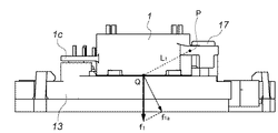
図1は、本発明の光量調節装置を適用した実施形態の絞り装置の分解斜視図である。図2は、図1の駆動ユニットの斜視図である。図3及び図4は、図1の絞り機構と駆動ユニットの組立方法を説明する側面図である。図5は、図4の部分断面図である。
[Light control device]
FIG. 1 is an exploded perspective view of a diaphragm device according to an embodiment to which the light amount adjusting device of the present invention is applied. FIG. 2 is a perspective view of the drive unit of FIG. 3 and 4 are side views for explaining a method of assembling the diaphragm mechanism and the drive unit of FIG. FIG. 5 is a partial cross-sectional view of FIG.
図1及び図2において、本実施形態の光量調節装置は、カバー部材1、ロータ2、ボビン5a,5b、ヨーク9、軸受部材10、位置検出器12、ケース部材13、ロータリープレート14、絞り羽根15、およびカムプレート16を備える。ここで、カバー部材1、ロータ2、ボビン5a,5b、ヨーク9、軸受部材10などによって駆動ユニットを構成する。また、位置検出器12、ケース部材13、ロータリープレート14、絞り羽根15、およびカムプレート16などによって絞り機構を構成する。
1 and 2, the light amount adjusting device of the present embodiment includes a
カバー部材1は、合成樹脂などの弾性材料で構成されており、ロータ2およびボビン5a,5bなどを収納する。カバー部材1の略中央部には、軸受穴1aが形成され、軸受穴1aの回りには、ボビン5a,5bの端子を挿通させる穴部1b−1〜1b−4が形成されている。また、カバー部材1の両側部には、それぞれ位置検出器12を押さえるための張り出し片1c、およびカバー部材1をケース部材13に押圧固定するための座部1dが設けられている。
The
張り出し片1cには、位置検出器12の端子部12aを挿通させる穴部1c−1〜1c−3、および位置検出器12の端面と接触する突起部1j(押圧部:図2参照)が設けられている。座部1dには、締結部材挿通穴1d−1、およびケース部材13に嵌合によって位置決めするための嵌合片部1e−1,1e−2が設けられている。また、座部1dの軸受穴1a寄りには、薄肉片部(薄肉部)1fが設けられている。
The projecting
また、カバー部材1には、ケース部材13にスナップフィット結合するための係止爪部(係止部)1k−2を先端に有する弾性片部1kが設けられている。また、カバー部材1には、ヨーク9を嵌合させて位置決めするための嵌合部1g−1,1g−2,1h−1〜1h−4,1i−1〜1i−4が設けられている。
Further, the
ロータ2は永久磁石で構成され、内周部に円盤状のコア3が接着などにより固定されている。コア3には回転軸4が圧入などにより嵌合固定されており、回転軸4のカバー部材1側の端部は該カバー部材の軸受穴1aに回転可能に支持されている。また、コア3と軸受部材10との間には、コア3の端面と軸受部材10の端面との摺動摩擦を低減させるためのワッシャ7が介装される。ワッシャ7は、潤滑性の高い材料で構成されている。
The
ボビン5a,5bは合成樹脂などで構成されており、給電のための端子部を有する。また、ボビン5a,5bには、コイル6a,6bが取り付けられるとともに、端子部にコイル引き出し線が絡げられて、半田によるメッキ処理が施されている。また、コイル6a,6bとヨーク9との間には、両者が導通しないようにするための絶縁性のシート部材8が介装される。このシート部材8には、軸受部材10の逃げ穴部8aとヨーク9の逃げ穴部8b−1,8b−2とが形成されている。
The bobbins 5a and 5b are made of synthetic resin or the like and have a terminal portion for supplying power. In addition, coils 6a and 6b are attached to the bobbins 5a and 5b, and coil lead wires are wound around the terminal portions and subjected to plating with solder. Further, an insulating sheet member 8 is interposed between the
ヨーク9は軟磁性材料で構成されており、ロータ2と径方向に対向するように曲げられたステータ部9b−1,9b−2、軸受部材10を圧入などにより固定するための穴部9a、およびカバー部材1と嵌合するための嵌合面部9c−1〜9c−6を有している。
The
軸受部材(軸受部)10は磁性材料で構成され、回転軸4のカバー部材1の反対側の端部を回転可能に支持する軸受穴10a、およびフランジ部10bを有する。軸受穴10aから突出する回転軸4の先端には、ピニオン11が固定される。ピニオン11は、回転軸4が圧入などにより固定されるための穴部11a、駆動ユニットの回転力をロータリープレート14に伝達するためのギヤ部11bを有する。
The bearing member (bearing portion) 10 is made of a magnetic material, and has a
位置検出器12は、フォトインタラプタなどの位置検出素子が用いられており、ロータリープレート14の回転位置を検出する。位置検出器12には、端子部12aが設けられている。
The
ケース部材13は合成樹脂などで構成されており、光軸方向に突出した突出部13aを有する。ケース部材13には、カバー部材1の座部1dの裏面が当接する受け面部13a−3、嵌合片部1e−1,1e−2の嵌合端面1e−1−a,1e−2−aが嵌合する嵌合突起部13a−2−aが設けられている。嵌合突起部13a−2は、裏面にも設けられている。
The
また、ケース部材13には、締結部材挿通穴1d−1に挿入された締結部材17を締め込むねじ穴部13a−1、ピニオン10の挿通穴部13b、軸受部材10のフランジ部10bの嵌合穴部13c、ヨーク9の端面を当接させる座面13dが設けられている。
Further, the
さらに、ケース部材13には、位置検出器12を収納する収納部13e、ロータリープレート14の遮蔽板部14aの逃げ穴13g、および弾性片部1kの挿通穴13fが設けられている。また、ケース部材13には、カムプレート16のスナップフィット部16b−1〜16b−3の挿通溝13h−1〜13h−3、位置決め軸16a−1、16a−2の嵌合穴および溝13i−1,13i−2が施されている。さらに、ケース部材13には、ロータリープレート14の嵌合リブ部14b−1〜14b−6が嵌合する嵌合穴部13jが設けられている。
Further, the
ロータリープレート(駆動部材)14は合成樹脂などで構成されており、位置検出器12の投射光を遮蔽するための検出片としての遮蔽板部14aが設けられている。また、ロータリープレート14には、嵌合穴部13jに嵌合してロータリープレート14を光軸中心に回転させるための嵌合リブ部14b−1〜14b−6が設けられている。
The rotary plate (drive member) 14 is made of synthetic resin or the like, and is provided with a shielding plate portion 14a as a detection piece for shielding the projection light of the
また、ロータリープレート14には、ピニオン11のギヤ部11bに噛合してロータリープレート14に回転駆動力を伝達するためのギヤ部14cが設けられている。さらに、ロータリープレート14には、絞り羽根15の嵌合軸部15a−1,15b−1,15c−1,15d−1,15e−1,15f−1が嵌合するための嵌合穴部14d−1〜14d−6が設けられている。
Further, the rotary plate 14 is provided with a gear portion 14 c that meshes with the gear portion 11 b of the
さらに、ロータリープレート14には、ケース部材13の端面に光軸方向に当接してロータリープレート14の光軸方向の位置を定めるための突起部14e−1〜14e−3(14e−3は不図示)が設けられている。突起部14e−1〜14e−3は、ほぼ光軸周りに等分に配置されている。ロータリープレート14の中央部には、開口14fが設けられている。
Further, the rotary plate 14 has
絞り羽根15は、合成樹脂または金属薄板などで構成され、嵌合穴部14d−1〜14d−6に嵌合する嵌合軸部15a−1,15b−1,15c−1,15d−1,15e−1,15f−1を有する。また、絞り羽根15には、カムプレート16のカム穴16c〜16hに係合する軸部15a−2,15b−2,15c−2,15d−2,15e−2,15f−2(15b−2,15c−2,15d−2は不図示)が設けられている。
The
カムプレート(カム部材)16は、カム穴16c〜16h、ケース部材13との位置決めのための軸部16a−1,16a−2を有する。また、カムプレート16には、ケース部材13にカムプレート16をスナップフィット結合させるためのスナップフィット部16b−1〜16b−3、および開口穴部16kが設けられている。
The cam plate (cam member) 16 includes cam holes 16 c to 16 h and
[駆動ユニットの組立手順]
次に、図1〜図4を参照して、駆動ユニットの組立手順について説明する。
[Assembly procedure of drive unit]
Next, the assembly procedure of the drive unit will be described with reference to FIGS.
まず、ヨーク9の穴部9aに軸受部材10の外径部を圧入などによって固定して、ヨーク9に軸受部材10を取り付ける。かかる状態においては、軸受部材10のフランジ部10bがヨーク9の端面に当接し、軸受部材10のヨーク9に対する位置決めがなされる。また、ヨーク9のステータ部9b−1,9b−2にシート部材8の穴部8b−1、8b−2を挿通させて、ヨーク9にシート部材8を敷設する。
First, the outer diameter portion of the bearing
次に、コイル6a,6bが取り付けられたボビン5a,5bの中空穴部(不図示)をヨーク9のステータ部9b−1,9b−2に挿通させる。次に、ロータ3と回転軸4とが一体となったロータユニットの回転軸4にワッシャ7を挿通させ、回転軸4先端を軸受部材10の穴部10aに嵌合させる。
Next, the hollow holes (not shown) of the bobbins 5a and 5b to which the
次に、ヨーク9をカバー部材1に取り付ける。かかる取り付けの際には、ヨーク9の嵌合面部9c−1−a〜9c−4−aおよび9c−5,9c−6が嵌合部1h−1〜1h−4,1g−1,1g−2にそれぞれ嵌合する。これにより、図2に示す状態となる。ここで、嵌合面部および嵌合部の一部、例えば嵌合面部9c−5,9c−6と嵌合部1g−1,1g−2とを圧入設定にすると、ヨーク9がカバー部材1に固定され、組立の際に不用意に分解して組み直すということがなくなる。そして、ピニオン11を回転軸4の先端部に圧入などにより固定することにより、駆動ユニットの組立が完了する。
Next, the
次に、図1〜図4を参照して、駆動ユニットのカバー部材1を絞り機構のケース部材13に取り付ける手順を説明する。
Next, a procedure for attaching the
まず、図3に示すように、駆動ユニットのカバー部材1を、光軸方向より絞り機構のケース部材13に移動させていく。その際、位置検出器12をケース部材13の収納部13eに収める。次に、カバー部材1をさらにケース部材13に接近させ、嵌合端面1e−1−a,1e−2−aをケース部材13の嵌合突起部13a−2−a,13a−2−b(不図示)にそれぞれ嵌合させる。また、軸受部材10のフランジ部10bの外径をケース部材13の穴部13cに嵌合させる。
First, as shown in FIG. 3, the
これらの嵌合により、カバー部材1がケース部材13に位置決めされ、また、嵌合と同時に穴部1c−1〜1c−3に端子部12aを挿通させる。そして、カバー部材1をさらにケース部材13に接近させると、座部1dの端面が受け面部13a−3に当接する。受け面部13a−3は傾斜面となっており、図1および図3に示すように、穴部13a−1の中心と穴部13cの中心とを結ぶ線方向にαの高低差が設けられ、穴部13c側の方が低くなっている。
By these fittings, the
次に、締結部材17によりカバー部材1をケース部材13に締め込んでいくと、座部1dの端面が高低差を持った受け面部13a−3に倣おうとして薄肉片部1fが弾性変形する。高低差αは穴部13a−1より穴部13c側の方が低くなっているので、この弾性変形により、ヨーク9の端面9eが座面13dに当接する力が発生する。この状態で、ヨーク9とケース部材13との光軸方向の位置が定まり、ピニオン11の位置が適切な位置に配置される。
Next, when the
これにより、ピニオン11のギヤ部11bとロータリープレート14のギヤ部14cとの良好な噛み合いが維持され、絞り羽根15による精度の良い開口径が得られる。なお、座部1dに設けられた突起部1d−2は、締結部材17が締め込まれた時に該締結部材17の端面が突起部1d−2を押圧することで、座部1dの端面を受け面部13a−3に積極的に倣わせようとするもので、薄肉片部1f寄りに設けられている。
Thereby, good meshing between the gear portion 11b of the
一方、カバー部材1をケース部材13に取り付けた状態では、図5に示すように、弾性片部1kの係止爪部1k−2の斜面部1k−1とケース部材13に施された係止爪部13kとが接触する。このとき、弾性片部1kが若干の撓み量を持つように斜面部1k−1の位置が設定されているため、図3を参照して、ヨーク9の端面9eの座面13dへの当接力(付勢力)を持ったまま、カバー部材1がケース部材13に保持される。
On the other hand, in the state where the
さらにこの状態では、図5に示すように、カバー部材1の突起部1jが位置検出器12の端面12bに当接し、張り出し片部1cが若干の撓み量を持って、位置検出器12を押圧保持している。
Furthermore, in this state, as shown in FIG. 5, the
ここで、図4および図5に示すように、弾性変形するカバー部材1の薄肉片部1fの略中心位置をP、ヨーク9の端面9eが座面13dへ当接する位置をQ、弾性片部1kの係止突起1k−2の斜面部1k−1が係止爪部13kと接触する位置をRとする。また、張り出し片部1cの突起部1jが位置検出器12の端面12bに当接する位置をSとする。
Here, as shown in FIGS. 4 and 5, P is the approximate center position of the thin piece 1 f of the
さらに、ヨーク部材9がQ点で座面13dを押圧する力f1の線分PQに対する垂直分力をf1a、カバー部材1がR点で受ける力f2の線分PRに対する垂直分力をf2a、カバー部材1がS点で受ける力f3の線分PSに対する垂直分力をf3aとする。
Further, the vertical component force f1a of the force f1 that the
そして、線分PQの長さをL1、線分PRの長さをL2、線分PSの長さをL3とすると、f1a・L1+f2a・L2>f3a・L3の関係を満足している。 When the length of the line segment PQ is L1, the length of the line segment PR is L2, and the length of the line segment PS is L3, the relationship f1a · L1 + f2a · L2> f3a · L3 is satisfied.
少なくとも上記の関係を満たすことにより、張り出し片部1cの突起部1jが受ける力に負けて、カバー部材1がケース部材13より浮き上がる(端面9eの座面13dへの当接力を得ない)といった不具合を回避することができる。従って、ピニオン11のギヤ部11bとロータリープレート14のギヤ部14cとの良好な噛み合いが維持され、絞り羽根15による精度の良い開口径が得られる。
By satisfying at least the above-mentioned relationship, the
以上説明したように、この実施の形態では、ロータリープレート14の遮蔽板部14aに対して位置検出器12をカバー部材1の付勢力により精度よく位置決め固定することができる。これにより、位置検出器12の位置ずれによる検出タイミングの変動を回避することができる。
As described above, in this embodiment, the
また、カバー部材1により光軸方向にケース部材13を押さえる構造にして、駆動ユニットを回転させずに光軸方向に組み込むようにしている。これにより、駆動ユニットを固定するためのフランジ部などを設ける必要がなくなり、省スペース化を実現することができる。
Further, the
なお、本発明は上記実施の形態に限定されるものではなく、本発明の要旨を逸脱しない範囲において適宜変更可能である。 In addition, this invention is not limited to the said embodiment, In the range which does not deviate from the summary of this invention, it can change suitably.
例えば、上記実施の形態では、カバー部材1に弾性片部1kを設けた場合を例示したが、f1a・L1>f3a・L3の関係を満足していれば、弾性片部1kを省略してもよい。
For example, in the above embodiment, the case where the
また、ケース部材13の受け面部13a−3は、必ずしも傾斜面である必要はない。例えば、突起部が設けられた受け面部13a−3と座部1dの端面とが押圧力を持って当接することで薄肉片部1fを弾性変形させ、ヨーク9の端面9eを座面13dへ付勢力を持って当接させるようにしてもよい。また、上記突起部は受け面部13a−3側ではなく座部1d側に設けてもよい。
Further, the receiving
さらに、ヨーク9の端面9eとケース部材13の座面13dとの当接は、複数個の突起部による接触であってもよい。また、カバー部材1とヨーク9とを圧入設定にした場合は、ヨーク9がカバー部材1に固定されるので、座面13dへの当接部をヨーク9の端面9eではなくカバー部材1の一部としてもよい。
Further, the contact between the
さて、上記構成の光量調節装置を1−2相駆動方式のステッピングモータで駆動した時には、図7、図8に模式的に示すようなトルク特性となる。 Now, when the light quantity adjusting device having the above configuration is driven by the stepping motor of the 1-2 phase driving system, the torque characteristics as schematically shown in FIGS. 7 and 8 are obtained.
図7は1相通電時の、あるロータ停止位置でのトルク特性、図8は2相通電時の、あるロータ停止位置でのトルク特性をそれぞれ示し、横軸はロータの回転角度、縦軸はトルクで、あるロータ位置を基準(0°)とした時の半周(180°)分の特性である。101はコイルに通電した時にロータに発生するトルク(コイル発生トルク)、102はコギングトルクを示している。図中の正方向は小絞り方向(もしくは開放方向)、負方向は開放方向(もしくは小絞り方向)である。103は正方向の摺動摩擦トルク(主に隣接する絞り羽根同士の摺動摩擦力に起因するトルク)、104は負方向の摺動摩擦トルク(主に隣接する絞り羽根同士の摺動摩擦力に起因するトルク)である。ただし、摺動摩擦トルクの正、負の方向は、コイル発生トルクやコギングトルクとは便宜上逆方向にしている。なお、小絞りとは、絞り値が最大(絞り開口径が最小)となるように制御された状態であり、開放とは、絞り値が最小(絞り開口径が最大)となるように制御された状態である。
FIG. 7 shows the torque characteristics at a certain rotor stop position during one-phase energization, FIG. 8 shows the torque characteristics at a certain rotor stop position during two-phase energization, the horizontal axis represents the rotor rotation angle, and the vertical axis represents The torque is a characteristic for a half circumference (180 °) when a certain rotor position is set as a reference (0 °).
105、108の黒抜き丸部はコイル発生トルクの磁気的安定位置である。また、106の黒点で示された位置はコギングトルクの磁気的安定位置である。
The
まず、1相駆動時である図7に着目すると、ロータ回転角75°の位置でコイル発生トルクとコギングトルクの磁気的安定位置が一致している。この状態でコイルへの通電を遮断すると、コギングトルクのみとなるが、コギングトルクの磁気的安定位置で停止しているため、ロータはその位置を維持した状態となる。 First, paying attention to FIG. 7 during one-phase driving, the magnetically stable positions of the coil generation torque and the cogging torque coincide at a position where the rotor rotation angle is 75 °. If the power supply to the coil is cut off in this state, only the cogging torque is obtained, but the rotor is maintained at that position because it stops at the magnetically stable position of the cogging torque.
一方、2相通電時である図8に着目すると、ロータ回転角90°の位置でコイル発生トルクの磁気的安定位置となるが、その位置ではコギングトルクは磁気的不安定位置となる。そのため、この状態でコイルへの通電を遮断すると、コギングトルクによりロータはロータ回転角75°の位置もしくは105°の位置へ移動して、コギングトルクの磁気的安定位置で停止する。ただし、これは摺動摩擦トルクを考慮しない場合であり、充分な摺動摩擦トルクがある場合は、コギングトルクの磁気的安定位置へ移動させるトルクに打ち勝って、ロータの回転移動を食い止めることができる。逆に摺動摩擦トルクが極めて少ない場合は、停止時のロータの振動などによりコギングトルクが摺動摩擦トルクよりも勝り、ロータが磁気的安定位置へ回転移動する。 On the other hand, when attention is paid to FIG. 8 during two-phase energization, the position of the rotor rotation angle of 90 ° is a magnetically stable position of the coil generation torque, but at that position, the cogging torque is a magnetically unstable position. Therefore, when the power supply to the coil is cut off in this state, the rotor moves to the position of the rotor rotation angle of 75 ° or 105 ° by the cogging torque and stops at the magnetically stable position of the cogging torque. However, this is a case where the sliding friction torque is not taken into consideration, and when there is a sufficient sliding friction torque, the rotational movement of the rotor can be stopped by overcoming the torque to be moved to the magnetically stable position of the cogging torque. On the other hand, when the sliding friction torque is extremely small, the cogging torque is superior to the sliding friction torque due to the vibration of the rotor at the time of stopping, and the rotor rotates and moves to a magnetically stable position.
図9は、開放〜小絞りまでの摺動摩擦トルクの変化を示している。111は従来の摺動摩擦トルク、112は絞り羽根が小絞り側へ作動する時に、絞り羽根が迫上がり始める時期である。迫上がりとは、複数の絞り羽根を周上に重ねて絞り開口を形成する場合に、絞り羽根全体として小絞りへ作動するほど開口部が光軸方向に突き出していく現象である。即ち、両隣りの絞り羽根が光軸方向にずれて配置されるため、中間絞り付近から小絞り側にかけて両隣の絞り羽根のエッジがその間の絞り羽根を押し上げて、絞り羽根全体が小絞りへ作動するほど開口部が光軸方向に突き出していく。113はコギングトルクの磁気的不安定位置で停止して通電を遮断した時に、磁気的安定位置へ移動しない限界の摺動摩擦トルクを示している。なお、中間絞りとは、小絞りと開放の中間にあたる絞り状態のことである。
FIG. 9 shows changes in the sliding friction torque from the open position to the small stop.
さて、図9の摺動摩擦トルクの変化をみると、摺動摩擦トルク111は、開放〜中間絞り付近では比較的摺動摩擦トルクは低く、コギングトルクの磁気的不安定位置で停止して通電を遮断した時に、磁気的安定位置へ移動してしまう。一方さらに絞り込むことで迫上がり始めると、急激に摺動摩擦トルクが増加していき、コギングトルクの磁気的不安定位置で停止して通電を遮断した時でも、磁気的安定位置へ移動することはなくなる。ただし、摺動摩擦トルクは大きければよいというわけではなく、それに打ち勝てるだけのコイル発生トルクが必要となり、闇雲に摺動トルクを増加させることは、装置の大型化や消費電力の増大につながり、好ましくない。
Now, looking at the change of the sliding friction torque in FIG. 9, the sliding
そこで、本例では、以下に説明する摩擦力付与手段により開放側から中間絞り付近までの摺動摩擦トルクを増加させ、小絞り側は摺動摩擦トルクを増加させない構成とし、コイル発生トルクを増やすことなく、絞り口径精度を向上させている。 Therefore, in this example, the frictional force applying means described below is used to increase the sliding friction torque from the open side to the vicinity of the middle diaphragm, and the small diaphragm side is configured not to increase the sliding friction torque without increasing the coil generation torque. The aperture diameter accuracy is improved.
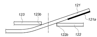
図10は、本発明を適用した光量調節装置の絞り羽根の開放状態を示している。図中121は複数の絞り羽根のうちの1枚の断面図を示しており、絞り羽根同士が摺接する先端部位には他の面と比較して摩擦係数の高い面(以下、高摩擦係数部分)121aが形成されている。この高摩擦係数部分121aは、全ての絞り羽根に形成されている。開放側から中間絞りの状態では、高摩擦係数部分121aが隣接する絞り羽根122の面122aと常時接触するため、これによる摺動摩擦力が得られる。
FIG. 10 shows an open state of the diaphragm blades of the light amount adjusting device to which the present invention is applied.
一方、図11は、本発明を適用した光量調節装置の絞り羽根の小絞り状態を示している。この状態では前述したように、隣接する絞り羽根122,123のエッジ部122a,123aが間に配置されている絞り羽根121を押し上げる。このメカニズムにより、絞り羽根全体として光軸方向に迫上がりが生じる。また、この状態では、迫上がりにより絞り羽根121の先端部の面121aは隣接する絞り羽根の面122aを離れるため、高摩擦係数部分121aによる摺動摩擦力は発生しない。
On the other hand, FIG. 11 shows a small aperture state of the aperture blade of the light amount adjusting device to which the present invention is applied. In this state, as described above, the
上記構成により、摺動摩擦トルクは図9の114のようになる。つまり、開放〜中間絞り付近のみ摺動摩擦トルクが増加して移動限界の摺動摩擦トルク113を超え、小絞り付近では摺動摩擦トルクは増加しない。従って、駆動部を大型にしたり、消費電力を増加させたりしてコイル発生トルクを上昇させる必要がなく、開放〜小絞りまで安定した絞り口径精度が得られる。
With the above configuration, the sliding friction torque is as indicated by 114 in FIG. That is, the sliding friction torque increases only in the vicinity of the open to middle aperture and exceeds the sliding
ところで、図10及び図11では、絞り羽根先端に他の面と比べて摩擦係数の高い面を形成したが、図12及び図13のように、先端部を屈曲させて隣接する絞り羽根の面を押圧する構成でも同様の効果が得られる。 In FIGS. 10 and 11, a surface having a higher coefficient of friction than the other surfaces is formed at the tip of the diaphragm blade. However, as shown in FIGS. The same effect can be obtained even in a configuration in which is pressed.
図12は、本発明を適用した光量調節装置の絞り羽根の開放状態を示している。絞り羽根131の先端には屈曲部131aと、隣接する絞り羽根132の端面に接触する接触面部131bが設けられている。開放から中間絞りの状態では、接触面部131bが隣接する絞り羽根132の端面に接触している。またこの状態では、若干絞り羽根を撓ませた状態となっているため、接触面部131bは隣接する絞り羽根132の端面を押圧しながら接触している。これにより開放から中間絞りで、摺動摩擦力を得ることができる。
FIG. 12 shows an open state of the diaphragm blades of the light amount adjusting device to which the present invention is applied. At the tip of the
一方図13は、本発明を適用した光量調節装置の絞り羽根の小絞り状態を示している。この状態では前述のように、迫上がり現象によって絞り羽根の先端部が持ち上がるため、接触面部131bは隣接する絞り羽根132の端面を離れ、摺動摩擦力を増加させることはない。
On the other hand, FIG. 13 shows a small aperture state of the aperture blade of the light amount adjusting device to which the present invention is applied. In this state, as described above, the leading end of the diaphragm blades is lifted by the uplift phenomenon, so that the
上記構成により、摺動摩擦トルクは図9の114のようになる。つまり、開放〜中間絞り付近のみ摺動摩擦トルクが増加して移動限界の摺動摩擦トルク113を超え、小絞り付近では摺動摩擦トルクは増加しない。従って、本構成においても、駆動部を大型にしたり、消費電力を増加させたりしてコイル発生トルクを上昇させる必要がなく、開放〜小絞りまで安定した絞り口径精度が得られる。なお、上記構成では、絞り羽根先端を屈曲させたが、各絞り羽根の全面を曲面形状に形成しても同様の効果が得られる。
With the above configuration, the sliding friction torque is as indicated by 114 in FIG. That is, the sliding friction torque increases only in the vicinity of the open to middle aperture and exceeds the sliding
ところで、前述の各構成では摺動摩擦力を絞り羽根によって発生させる形態であったが、絞り羽根に当接して案内するカムプレートと、カムプレートに沿って作動する絞り羽根との係合部に摺動摩擦力を発生させる構成でもよい。即ち、カムプレートのカム穴(図1の16c〜16h)側面と絞り羽根の軸部(図1の15a−2〜15f−2)が係合する構成において、カム側面の摩擦係数を小絞り側よりも開放側が高くなるように形成することで前述と同様の効果が得られる。 By the way, in each of the above-mentioned configurations, the sliding frictional force is generated by the diaphragm blades. The structure which generate | occur | produces dynamic friction force may be sufficient. That is, in a configuration in which the cam hole (16c to 16h in FIG. 1) side surface and the shaft portion (15a-2 to 15f-2 in FIG. 1) of the aperture plate engage with each other, the friction coefficient on the cam side surface is reduced to the small aperture side. By forming so that the open side is higher than the above, the same effect as described above can be obtained.
さらに、軸部の軸方向に直交する方向に力(側圧)が加わった時に、軸部が弾性的に変形するように構成し、カム穴の幅寸法を軸部直径よりも若干小さくする。そして、開放側と小絞り側で徐々に変化(例えば、開放側の幅寸法<小絞り側の幅寸法)させて軸部への側圧を変化させることで、軸部に作用する摺動摩擦力を開放〜小絞り間で変化させるようにすれば、前述と同様の効果が得られる。 Further, the shaft portion is configured to be elastically deformed when a force (side pressure) is applied in a direction orthogonal to the axial direction of the shaft portion, and the width dimension of the cam hole is made slightly smaller than the shaft portion diameter. Then, the sliding friction force acting on the shaft portion is changed by gradually changing the opening side and the small aperture side (for example, the width dimension on the open side <the width size on the small aperture side) to change the side pressure to the shaft portion. The effect similar to the above can be obtained by changing between the wide open and the small aperture.
1 カバー部材
1d−2 薄肉片部(薄肉部)
1j 突起部(押圧部)
1k 弾性片部
1k−2 係止爪部(係止部)
2 ロータ
3 コア
4 回転軸
6 コイル
7 ワッシャ
8 シート部材
9 ヨーク
10 軸受部材(軸受部)
11 ピニオン
12 位置検出器
13 ケース部材
14 ロータリープレート(駆動部材)
15 絞り羽根
16 カムプレート(カム部材)
1
1j Protruding part (pressing part)
2
11
15
Claims (4)
前記絞り羽根は、前記絞り開口が開放状態となるときに前記絞り羽根同士が重なり合って前記絞り羽根の先端部が隣接する他の絞り羽根に接触し、前記絞り開口が小絞り状態となるときに前記絞り羽根の前記先端部が押し上げられて隣接する他の絞り羽根と接触しないものであって、
前記ステッピングモータへの通電を遮断した際にロータに作用するコギングトルクを超えるように、前記絞り羽根の前記先端部に前記絞り羽根の他の面よりも高い摩擦係数を有する高摩擦係数部を形成することを特徴とする光量調節装置。 Includes a plurality of diaphragm blades for forming the aperture stop is disposed so as to overlap each other, a stepping motor for driving the diaphragm blades, and a cam member which abuts the guide with the diaphragm blades, Ri by said stepping motor a light amount adjusting device for adjusting an opening degree of the throttle opening of the diaphragm blades of the multiple is actuated along said cam member,
When the aperture opening is in an open state, the aperture blades are overlapped with each other so that the front end of the aperture blade contacts another adjacent aperture blade, and the aperture opening is in a small aperture state. The tip of the diaphragm blade is pushed up and does not come into contact with other adjacent diaphragm blades,
A high coefficient of friction portion having a higher coefficient of friction than the other surface of the diaphragm blade is formed at the tip of the diaphragm blade so as to exceed the cogging torque acting on the rotor when the energization to the stepping motor is cut off. A light amount adjusting device characterized by that.
前記ステッピングモータへの通電を遮断した際にロータに作用するコギングトルクを超えるように、前記絞り開口が開放状態となるときに前記絞り羽根の前記軸部が当接するカム穴の側面の摩擦係数を、前記絞り開口が小絞り状態となるときに前記絞り羽根の前記軸部が当接するカム穴の側面の摩擦係数より高くすることを特徴とする光量調節装置。 A plurality of aperture blades that are arranged so as to overlap each other and that form an aperture opening, a stepping motor that drives the aperture blades , and a cam member that is formed with a cam hole that contacts and guides the shaft portion of the aperture blades A light amount adjusting device that adjusts the opening of the aperture opening by operating the plurality of aperture blades along the cam hole by the stepping motor;
The friction coefficient of the side surface of the cam hole with which the shaft portion of the aperture blade abuts when the aperture opening is opened so that the cogging torque acting on the rotor when the energization to the stepping motor is interrupted is exceeded. The light quantity adjusting device is characterized in that the coefficient of friction is set to be higher than the friction coefficient of the side surface of the cam hole with which the shaft portion of the diaphragm blade abuts when the aperture opening is in a small aperture state .
複数のレンズを有する光学系と、
前記光量調節装置と前記光学系とを制御する制御部と、を有するレンズ装置。 A light amount adjustment equipment according to claim 1 or 2,
An optical system having a plurality of lenses;
A lens device comprising: a control unit that controls the light amount adjusting device and the optical system.
前記レンズ装置が着脱自在なカメラ装置と、を備えることを特徴とするカメラシステム。 A lens device according to claim 3 ;
A camera system comprising: a camera device to which the lens device is detachable.
Priority Applications (1)
| Application Number | Priority Date | Filing Date | Title |
|---|---|---|---|
| JP2007312660A JP5368697B2 (en) | 2007-12-03 | 2007-12-03 | Light control device, lens device, camera system |
Applications Claiming Priority (1)
| Application Number | Priority Date | Filing Date | Title |
|---|---|---|---|
| JP2007312660A JP5368697B2 (en) | 2007-12-03 | 2007-12-03 | Light control device, lens device, camera system |
Publications (3)
| Publication Number | Publication Date |
|---|---|
| JP2009139431A JP2009139431A (en) | 2009-06-25 |
| JP2009139431A5 JP2009139431A5 (en) | 2011-01-20 |
| JP5368697B2 true JP5368697B2 (en) | 2013-12-18 |
Family
ID=40870130
Family Applications (1)
| Application Number | Title | Priority Date | Filing Date |
|---|---|---|---|
| JP2007312660A Expired - Fee Related JP5368697B2 (en) | 2007-12-03 | 2007-12-03 | Light control device, lens device, camera system |
Country Status (1)
| Country | Link |
|---|---|
| JP (1) | JP5368697B2 (en) |
Cited By (1)
| Publication number | Priority date | Publication date | Assignee | Title |
|---|---|---|---|---|
| CN110603486A (en) * | 2017-05-09 | 2019-12-20 | 深圳市大疆创新科技有限公司 | Light amount adjustment device, imaging system, and moving object |
Families Citing this family (1)
| Publication number | Priority date | Publication date | Assignee | Title |
|---|---|---|---|---|
| JP6380079B2 (en) * | 2014-12-17 | 2018-08-29 | コニカミノルタ株式会社 | Rotating member position detecting device and lens barrel |
Family Cites Families (7)
| Publication number | Priority date | Publication date | Assignee | Title |
|---|---|---|---|---|
| JP2584804B2 (en) * | 1987-12-17 | 1997-02-26 | キヤノン株式会社 | Stepping motor |
| JP3683325B2 (en) * | 1996-02-29 | 2005-08-17 | 日本電産コパル株式会社 | Pulse motor for camera drive |
| JP3800719B2 (en) * | 1997-05-06 | 2006-07-26 | 日本精工株式会社 | Electric linear actuator |
| JP2001069793A (en) * | 1999-08-31 | 2001-03-16 | Canon Inc | Driving device with stepping motor and device with the driving device, light quantity adjusting device, and optical equipment |
| JP4054618B2 (en) * | 2001-12-25 | 2008-02-27 | オリンパス株式会社 | Light intensity adjustment unit |
| JP2006042465A (en) * | 2004-07-26 | 2006-02-09 | Toyota Motor Corp | Motor with brake mechanism |
| JP2006113256A (en) * | 2004-10-14 | 2006-04-27 | Canon Inc | Light quantity controller |
-
2007
- 2007-12-03 JP JP2007312660A patent/JP5368697B2/en not_active Expired - Fee Related
Cited By (2)
| Publication number | Priority date | Publication date | Assignee | Title |
|---|---|---|---|---|
| CN110603486A (en) * | 2017-05-09 | 2019-12-20 | 深圳市大疆创新科技有限公司 | Light amount adjustment device, imaging system, and moving object |
| US11073257B2 (en) | 2017-05-09 | 2021-07-27 | SZ DJI Technology Co., Ltd. | Light amount adjustment device, imaging device, imaging system and moving object |
Also Published As
| Publication number | Publication date |
|---|---|
| JP2009139431A (en) | 2009-06-25 |
Similar Documents
| Publication | Publication Date | Title |
|---|---|---|
| US7053514B2 (en) | Image apparatus and drive motor | |
| US7806605B2 (en) | Light amount adjustment apparatus and image pickup apparatus | |
| JP4189412B2 (en) | Electromagnetic drive device and light amount adjustment device using the same | |
| KR101272003B1 (en) | Drive mechanism, blade drive mechanism and optical device | |
| US6792204B2 (en) | Electronic shutter for camera and method for controlling the same | |
| JP5368697B2 (en) | Light control device, lens device, camera system | |
| JP2009008853A (en) | Light quantity adjusting device, lens device and camera system | |
| JP5173293B2 (en) | Light control device | |
| JP4901551B2 (en) | Blade driving device and imaging device | |
| JP5349848B2 (en) | Light amount adjusting device having diaphragm blades and method of manufacturing diaphragm blades | |
| JP3181777B2 (en) | Interchangeable lens camera | |
| JP5064757B2 (en) | Light control device | |
| JP2002099017A (en) | Blur correcting apparatus | |
| JP6513182B2 (en) | Imaging device | |
| JP2017116642A (en) | Light-amount adjustment device and lens barrel using the same, and optical instrument using the same | |
| JP2003090948A (en) | Optical equipment | |
| JP2012159637A (en) | Light quantity adjustment device and optical apparatus having the same | |
| WO2016147259A1 (en) | Imaging device | |
| JP5134230B2 (en) | Electromagnetic actuator and camera blade drive device using the same | |
| KR100261600B1 (en) | Electronic shutter operating device | |
| JP2007199578A (en) | Aperture adjustment device and imaging apparatus | |
| JP2004191750A (en) | Light amount control device | |
| JP2006296142A (en) | Electromagnetic drive and quantity-of-light control device having the same | |
| JP2002318339A (en) | Focusing mode switching device for camera lens | |
| JP2013020165A (en) | Light quantity adjusting device and optical apparatus with the same |
Legal Events
| Date | Code | Title | Description |
|---|---|---|---|
| A521 | Written amendment |
Free format text: JAPANESE INTERMEDIATE CODE: A523 Effective date: 20101201 |
|
| A621 | Written request for application examination |
Free format text: JAPANESE INTERMEDIATE CODE: A621 Effective date: 20101201 |
|
| A977 | Report on retrieval |
Free format text: JAPANESE INTERMEDIATE CODE: A971007 Effective date: 20121018 |
|
| A131 | Notification of reasons for refusal |
Free format text: JAPANESE INTERMEDIATE CODE: A131 Effective date: 20121102 |
|
| A521 | Written amendment |
Free format text: JAPANESE INTERMEDIATE CODE: A523 Effective date: 20121221 |
|
| TRDD | Decision of grant or rejection written | ||
| A01 | Written decision to grant a patent or to grant a registration (utility model) |
Free format text: JAPANESE INTERMEDIATE CODE: A01 Effective date: 20130816 |
|
| A61 | First payment of annual fees (during grant procedure) |
Free format text: JAPANESE INTERMEDIATE CODE: A61 Effective date: 20130913 |
|
| R151 | Written notification of patent or utility model registration |
Ref document number: 5368697 Country of ref document: JP Free format text: JAPANESE INTERMEDIATE CODE: R151 |
|
| LAPS | Cancellation because of no payment of annual fees |