WO2018199178A1 - Multi-layered glass manufacturing method and multi-layered glass - Google Patents
Multi-layered glass manufacturing method and multi-layered glass Download PDFInfo
- Publication number
- WO2018199178A1 WO2018199178A1 PCT/JP2018/016849 JP2018016849W WO2018199178A1 WO 2018199178 A1 WO2018199178 A1 WO 2018199178A1 JP 2018016849 W JP2018016849 W JP 2018016849W WO 2018199178 A1 WO2018199178 A1 WO 2018199178A1
- Authority
- WO
- WIPO (PCT)
- Prior art keywords
- spacer
- glass
- adhesive
- glass plate
- molecular weight
- Prior art date
Links
Images


Classifications
-
- B—PERFORMING OPERATIONS; TRANSPORTING
- B32—LAYERED PRODUCTS
- B32B—LAYERED PRODUCTS, i.e. PRODUCTS BUILT-UP OF STRATA OF FLAT OR NON-FLAT, e.g. CELLULAR OR HONEYCOMB, FORM
- B32B17/00—Layered products essentially comprising sheet glass, or glass, slag, or like fibres
- B32B17/06—Layered products essentially comprising sheet glass, or glass, slag, or like fibres comprising glass as the main or only constituent of a layer, next to another layer of a specific material
- B32B17/10—Layered products essentially comprising sheet glass, or glass, slag, or like fibres comprising glass as the main or only constituent of a layer, next to another layer of a specific material of synthetic resin
- B32B17/10005—Layered products essentially comprising sheet glass, or glass, slag, or like fibres comprising glass as the main or only constituent of a layer, next to another layer of a specific material of synthetic resin laminated safety glass or glazing
- B32B17/10009—Layered products essentially comprising sheet glass, or glass, slag, or like fibres comprising glass as the main or only constituent of a layer, next to another layer of a specific material of synthetic resin laminated safety glass or glazing characterized by the number, the constitution or treatment of glass sheets
- B32B17/10036—Layered products essentially comprising sheet glass, or glass, slag, or like fibres comprising glass as the main or only constituent of a layer, next to another layer of a specific material of synthetic resin laminated safety glass or glazing characterized by the number, the constitution or treatment of glass sheets comprising two outer glass sheets
- B32B17/10045—Layered products essentially comprising sheet glass, or glass, slag, or like fibres comprising glass as the main or only constituent of a layer, next to another layer of a specific material of synthetic resin laminated safety glass or glazing characterized by the number, the constitution or treatment of glass sheets comprising two outer glass sheets with at least one intermediate layer consisting of a glass sheet
- B32B17/10055—Layered products essentially comprising sheet glass, or glass, slag, or like fibres comprising glass as the main or only constituent of a layer, next to another layer of a specific material of synthetic resin laminated safety glass or glazing characterized by the number, the constitution or treatment of glass sheets comprising two outer glass sheets with at least one intermediate layer consisting of a glass sheet with at least one intermediate air space
-
- B—PERFORMING OPERATIONS; TRANSPORTING
- B32—LAYERED PRODUCTS
- B32B—LAYERED PRODUCTS, i.e. PRODUCTS BUILT-UP OF STRATA OF FLAT OR NON-FLAT, e.g. CELLULAR OR HONEYCOMB, FORM
- B32B17/00—Layered products essentially comprising sheet glass, or glass, slag, or like fibres
- B32B17/06—Layered products essentially comprising sheet glass, or glass, slag, or like fibres comprising glass as the main or only constituent of a layer, next to another layer of a specific material
- B32B17/10—Layered products essentially comprising sheet glass, or glass, slag, or like fibres comprising glass as the main or only constituent of a layer, next to another layer of a specific material of synthetic resin
- B32B17/10005—Layered products essentially comprising sheet glass, or glass, slag, or like fibres comprising glass as the main or only constituent of a layer, next to another layer of a specific material of synthetic resin laminated safety glass or glazing
- B32B17/10807—Making laminated safety glass or glazing; Apparatus therefor
- B32B17/10816—Making laminated safety glass or glazing; Apparatus therefor by pressing
-
- C—CHEMISTRY; METALLURGY
- C03—GLASS; MINERAL OR SLAG WOOL
- C03C—CHEMICAL COMPOSITION OF GLASSES, GLAZES OR VITREOUS ENAMELS; SURFACE TREATMENT OF GLASS; SURFACE TREATMENT OF FIBRES OR FILAMENTS MADE FROM GLASS, MINERALS OR SLAGS; JOINING GLASS TO GLASS OR OTHER MATERIALS
- C03C27/00—Joining pieces of glass to pieces of other inorganic material; Joining glass to glass other than by fusing
- C03C27/06—Joining glass to glass by processes other than fusing
- C03C27/10—Joining glass to glass by processes other than fusing with the aid of adhesive specially adapted for that purpose
-
- C—CHEMISTRY; METALLURGY
- C08—ORGANIC MACROMOLECULAR COMPOUNDS; THEIR PREPARATION OR CHEMICAL WORKING-UP; COMPOSITIONS BASED THEREON
- C08G—MACROMOLECULAR COMPOUNDS OBTAINED OTHERWISE THAN BY REACTIONS ONLY INVOLVING UNSATURATED CARBON-TO-CARBON BONDS
- C08G18/00—Polymeric products of isocyanates or isothiocyanates
- C08G18/06—Polymeric products of isocyanates or isothiocyanates with compounds having active hydrogen
- C08G18/28—Polymeric products of isocyanates or isothiocyanates with compounds having active hydrogen characterised by the compounds used containing active hydrogen
- C08G18/2805—Compounds having only one group containing active hydrogen
- C08G18/288—Compounds containing at least one heteroatom other than oxygen or nitrogen
- C08G18/289—Compounds containing at least one heteroatom other than oxygen or nitrogen containing silicon
-
- C—CHEMISTRY; METALLURGY
- C08—ORGANIC MACROMOLECULAR COMPOUNDS; THEIR PREPARATION OR CHEMICAL WORKING-UP; COMPOSITIONS BASED THEREON
- C08G—MACROMOLECULAR COMPOUNDS OBTAINED OTHERWISE THAN BY REACTIONS ONLY INVOLVING UNSATURATED CARBON-TO-CARBON BONDS
- C08G18/00—Polymeric products of isocyanates or isothiocyanates
- C08G18/06—Polymeric products of isocyanates or isothiocyanates with compounds having active hydrogen
- C08G18/28—Polymeric products of isocyanates or isothiocyanates with compounds having active hydrogen characterised by the compounds used containing active hydrogen
- C08G18/40—High-molecular-weight compounds
- C08G18/62—Polymers of compounds having carbon-to-carbon double bonds
- C08G18/6204—Polymers of olefins
- C08G18/6208—Hydrogenated polymers of conjugated dienes
-
- C—CHEMISTRY; METALLURGY
- C08—ORGANIC MACROMOLECULAR COMPOUNDS; THEIR PREPARATION OR CHEMICAL WORKING-UP; COMPOSITIONS BASED THEREON
- C08G—MACROMOLECULAR COMPOUNDS OBTAINED OTHERWISE THAN BY REACTIONS ONLY INVOLVING UNSATURATED CARBON-TO-CARBON BONDS
- C08G18/00—Polymeric products of isocyanates or isothiocyanates
- C08G18/06—Polymeric products of isocyanates or isothiocyanates with compounds having active hydrogen
- C08G18/28—Polymeric products of isocyanates or isothiocyanates with compounds having active hydrogen characterised by the compounds used containing active hydrogen
- C08G18/40—High-molecular-weight compounds
- C08G18/62—Polymers of compounds having carbon-to-carbon double bonds
- C08G18/6216—Polymers of alpha-beta ethylenically unsaturated carboxylic acids or of derivatives thereof
- C08G18/622—Polymers of esters of alpha-beta ethylenically unsaturated carboxylic acids
- C08G18/6225—Polymers of esters of acrylic or methacrylic acid
- C08G18/6229—Polymers of hydroxy groups containing esters of acrylic or methacrylic acid with aliphatic polyalcohols
-
- C—CHEMISTRY; METALLURGY
- C08—ORGANIC MACROMOLECULAR COMPOUNDS; THEIR PREPARATION OR CHEMICAL WORKING-UP; COMPOSITIONS BASED THEREON
- C08G—MACROMOLECULAR COMPOUNDS OBTAINED OTHERWISE THAN BY REACTIONS ONLY INVOLVING UNSATURATED CARBON-TO-CARBON BONDS
- C08G18/00—Polymeric products of isocyanates or isothiocyanates
- C08G18/06—Polymeric products of isocyanates or isothiocyanates with compounds having active hydrogen
- C08G18/70—Polymeric products of isocyanates or isothiocyanates with compounds having active hydrogen characterised by the isocyanates or isothiocyanates used
- C08G18/72—Polyisocyanates or polyisothiocyanates
- C08G18/73—Polyisocyanates or polyisothiocyanates acyclic
-
- C—CHEMISTRY; METALLURGY
- C08—ORGANIC MACROMOLECULAR COMPOUNDS; THEIR PREPARATION OR CHEMICAL WORKING-UP; COMPOSITIONS BASED THEREON
- C08G—MACROMOLECULAR COMPOUNDS OBTAINED OTHERWISE THAN BY REACTIONS ONLY INVOLVING UNSATURATED CARBON-TO-CARBON BONDS
- C08G18/00—Polymeric products of isocyanates or isothiocyanates
- C08G18/06—Polymeric products of isocyanates or isothiocyanates with compounds having active hydrogen
- C08G18/70—Polymeric products of isocyanates or isothiocyanates with compounds having active hydrogen characterised by the isocyanates or isothiocyanates used
- C08G18/72—Polyisocyanates or polyisothiocyanates
- C08G18/74—Polyisocyanates or polyisothiocyanates cyclic
- C08G18/75—Polyisocyanates or polyisothiocyanates cyclic cycloaliphatic
- C08G18/751—Polyisocyanates or polyisothiocyanates cyclic cycloaliphatic containing only one cycloaliphatic ring
- C08G18/752—Polyisocyanates or polyisothiocyanates cyclic cycloaliphatic containing only one cycloaliphatic ring containing at least one isocyanate or isothiocyanate group linked to the cycloaliphatic ring by means of an aliphatic group
- C08G18/753—Polyisocyanates or polyisothiocyanates cyclic cycloaliphatic containing only one cycloaliphatic ring containing at least one isocyanate or isothiocyanate group linked to the cycloaliphatic ring by means of an aliphatic group containing one isocyanate or isothiocyanate group linked to the cycloaliphatic ring by means of an aliphatic group having a primary carbon atom next to the isocyanate or isothiocyanate group
- C08G18/755—Polyisocyanates or polyisothiocyanates cyclic cycloaliphatic containing only one cycloaliphatic ring containing at least one isocyanate or isothiocyanate group linked to the cycloaliphatic ring by means of an aliphatic group containing one isocyanate or isothiocyanate group linked to the cycloaliphatic ring by means of an aliphatic group having a primary carbon atom next to the isocyanate or isothiocyanate group and at least one isocyanate or isothiocyanate group linked to a secondary carbon atom of the cycloaliphatic ring, e.g. isophorone diisocyanate
-
- C—CHEMISTRY; METALLURGY
- C09—DYES; PAINTS; POLISHES; NATURAL RESINS; ADHESIVES; COMPOSITIONS NOT OTHERWISE PROVIDED FOR; APPLICATIONS OF MATERIALS NOT OTHERWISE PROVIDED FOR
- C09J—ADHESIVES; NON-MECHANICAL ASPECTS OF ADHESIVE PROCESSES IN GENERAL; ADHESIVE PROCESSES NOT PROVIDED FOR ELSEWHERE; USE OF MATERIALS AS ADHESIVES
- C09J175/00—Adhesives based on polyureas or polyurethanes; Adhesives based on derivatives of such polymers
- C09J175/04—Polyurethanes
-
- E—FIXED CONSTRUCTIONS
- E06—DOORS, WINDOWS, SHUTTERS, OR ROLLER BLINDS IN GENERAL; LADDERS
- E06B—FIXED OR MOVABLE CLOSURES FOR OPENINGS IN BUILDINGS, VEHICLES, FENCES OR LIKE ENCLOSURES IN GENERAL, e.g. DOORS, WINDOWS, BLINDS, GATES
- E06B3/00—Window sashes, door leaves, or like elements for closing wall or like openings; Layout of fixed or moving closures, e.g. windows in wall or like openings; Features of rigidly-mounted outer frames relating to the mounting of wing frames
- E06B3/66—Units comprising two or more parallel glass or like panes permanently secured together
- E06B3/663—Elements for spacing panes
- E06B3/66309—Section members positioned at the edges of the glazing unit
- E06B3/66328—Section members positioned at the edges of the glazing unit of rubber, plastics or similar materials
-
- E—FIXED CONSTRUCTIONS
- E06—DOORS, WINDOWS, SHUTTERS, OR ROLLER BLINDS IN GENERAL; LADDERS
- E06B—FIXED OR MOVABLE CLOSURES FOR OPENINGS IN BUILDINGS, VEHICLES, FENCES OR LIKE ENCLOSURES IN GENERAL, e.g. DOORS, WINDOWS, BLINDS, GATES
- E06B3/00—Window sashes, door leaves, or like elements for closing wall or like openings; Layout of fixed or moving closures, e.g. windows in wall or like openings; Features of rigidly-mounted outer frames relating to the mounting of wing frames
- E06B3/66—Units comprising two or more parallel glass or like panes permanently secured together
- E06B3/663—Elements for spacing panes
- E06B3/66309—Section members positioned at the edges of the glazing unit
- E06B3/66342—Section members positioned at the edges of the glazing unit characterised by their sealed connection to the panes
- E06B3/66352—Section members positioned at the edges of the glazing unit characterised by their sealed connection to the panes with separate sealing strips between the panes and the spacer
-
- E—FIXED CONSTRUCTIONS
- E06—DOORS, WINDOWS, SHUTTERS, OR ROLLER BLINDS IN GENERAL; LADDERS
- E06B—FIXED OR MOVABLE CLOSURES FOR OPENINGS IN BUILDINGS, VEHICLES, FENCES OR LIKE ENCLOSURES IN GENERAL, e.g. DOORS, WINDOWS, BLINDS, GATES
- E06B3/00—Window sashes, door leaves, or like elements for closing wall or like openings; Layout of fixed or moving closures, e.g. windows in wall or like openings; Features of rigidly-mounted outer frames relating to the mounting of wing frames
- E06B3/66—Units comprising two or more parallel glass or like panes permanently secured together
- E06B3/673—Assembling the units
- E06B3/67326—Assembling spacer elements with the panes
- E06B3/6733—Assembling spacer elements with the panes by applying, e.g. extruding, a ribbon of hardenable material on or between the panes
Definitions
- the present invention relates to a method for producing a multilayer glass and a multilayer glass.
- a multi-layer glass in which a plurality of glass plates are arranged to face each other via a spacer and a hollow layer is formed between the glass plates, and the spacer and the glass plate are bonded via an adhesive.
- a multilayer glass having a thickness of 0.5 mm or less for each adhesive layer is known (for example, see Patent Document 1).
- an object of the present invention is to provide a method for producing a double-glazed glass and a double-glazed glass capable of significantly reducing the drying time after bonding a spacer to a glass plate.
- a method for producing a multilayer glass includes a multilayer in which a plurality of glass plates are arranged to face each other via a spacer, and a hollow layer is formed between the glass plates.
- a method for producing glass Applying an adhesive to at least one of the plurality of glass plates; Adhering the spacer to the glass plate coated with the adhesive at a temperature of 50 ° C. or more and 160 ° C. or less,
- the spacer is formed of a thermoplastic resin material containing butyl rubber.
- FIG. 1 It is a principal part schematic sectional drawing which shows an example of the fundamental structure of the multilayer glass which concerns on embodiment of this invention. It is a principal part schematic sectional drawing which shows another example of the multilayer glass which concerns on embodiment of this invention. It is the figure which showed a series of processes of the manufacturing method of the multilayer glass 10 which concerns on the 1st Embodiment of this invention. It is the figure which showed a series of processes of the manufacturing method of the multilayer glass which concerns on the 2nd Embodiment of this invention. It is the figure which showed a series of processes of the manufacturing method of the multilayer glass which concerns on the 3rd Embodiment of this invention.
- 3 is a view showing the structure of an adhesive evaluation sample for evaluating the adhesiveness of Examples 1 to 12 and Comparative Examples 1 to 3.
- 3 is a table showing combined configurations and evaluation results of Examples 1 to 12.
- 6 is a table showing the combined configurations and evaluation results of Comparative Examples 1 to 3.
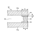
- FIG. 1 is a schematic cross-sectional view of an essential part showing an example of a basic configuration of the multilayer glass of the present invention.
- the glass plates 11a and 11b are arranged to face each other with a predetermined interval by a resin spacer 12, and a hollow layer 15 is formed between the glass plates 11a and 11b to constitute the multilayer glass 10.
- adhesive layers 14 are formed between the spacer 12 and the glass plate 11a and between the spacer 12 and the glass plate 11b, respectively.
- the thickness a of the adhesive layer 14 is not less than 0.1 ⁇ m and not more than 50 ⁇ m.
- the spacer 12 is formed from a resin material and contains a hygroscopic agent in the resin material.
- a hygroscopic agent zeolite, silica gel or the like can be used, and zeolite is preferable because of its high hygroscopic performance in a low humidity region.
- the shape of the zeolite there is no particular limitation on the shape of the zeolite, and from the viewpoint of uniform dispersibility in the resin material for the spacer, a powdery one is preferable.
- the pore diameter is not particularly limited as long as it absorbs water vapor, and 4A zeolite powder that can be obtained at low cost is desirable.
- the moisture absorption performance of the spacer resin material is greatly influenced by environmental conditions such as temperature and humidity, so it is not easy to define, but at least the temperature range of ⁇ 20 ° C to + 60 ° C, which is the operating temperature range of double-glazed glass Therefore, it is desirable to have a moisture absorption performance of 0.1% or more with respect to the weight of the sealing material.
- thermoplastic resin material As the resin material forming the spacer 12, a thermoplastic resin material is used in view of the fact that the drying time (curing time) after the production of the multilayer glass 10 can be shortened.
- a resin material containing a butyl rubber-based material is used so that sufficient low moisture permeability can be obtained as a spacer of the multilayer glass.
- a material that contributes to increasing the hardness such as crystalline polyolefin, so that sufficient shape retention as the spacer 12 of the multilayer glass 10 can be obtained.
- thermoplastic resin material used as the material of the spacer 12 of the multilayer glass 10 according to the present embodiment includes butyl rubber.
- the butyl rubber contained in the thermoplastic resin material includes two types of materials: a high molecular weight side material constituting the high molecular weight butyl rubber and a low molecular weight side material constituting the low molecular weight butyl rubber. .
- the high molecular weight butyl rubber and the low molecular weight butyl rubber have almost the same chemical structure but different molecular weights. Since the chemical structure is the same, the gas permeability and chemical resistance are the same, but the physical properties such as melt viscosity and elastic modulus are different due to the different molecular weight. High molecular weight butyl rubber is a block-like solid and exhibits properties as an elastomer. On the other hand, the low molecular weight butyl rubber exhibits properties as a viscous liquid and an adhesive.
- the difference in physical properties due to the molecular weight of the butyl rubber is utilized in order to increase the fluidity at high temperatures (decrease the melt viscosity) while maintaining the elastic modulus at room temperature. To do. The contents will be described below.
- the molecular weight of the high molecular weight butyl rubber is greatly affected. Therefore, when selecting the high molecular weight butyl rubber, the range showing the physical properties (high elastomeric properties and elasticity) of the high molecular weight butyl rubber. Therefore, it is preferable to use a material having a lower molecular weight.
- the high molecular weight butyl rubber it is preferable to use a material having a number average molecular weight of 55,000 to 150,000, more preferably a material having a number average molecular weight of 60000 to 120,000, and a number average molecular weight. It is more preferable to use a material having a molecular weight of 65,000 or more and 100,000 or less, and it is particularly preferable to use a material having a number average molecular weight of 70,000 or more and 80,000 or less.
- the selection of the low molecular weight butyl rubber has a higher molecular weight within the range showing the physical properties (high viscosity) of the low molecular weight butyl rubber. It is preferable to select the material on the side.
- the low molecular weight butyl rubber a material having a number average molecular weight of 35000 or more and 50000 or less is preferably used, and a material having a number average molecular weight of 38000 or more and 45000 or less is more preferably used.
- a duplicate glass 10 having a high-quality spacer 12 is manufactured while maintaining the elastic modulus at room temperature while reducing the melt viscosity at high temperature and increasing the productivity. And can be configured.
- the spacer 12 is preferably provided between a plurality of glass plates by extruding a resin material in the form of a spacer directly on one glass plate and then pressing between the other glass plates in view of automation of the manufacturing process of the multi-layer glass 10. .
- a resin material is directly extruded in a spacer shape between a plurality of glass plates 11a and 11b held at intervals, and provided between a plurality of glass plates 11a and 11b, or a resin material separately.
- the spacer 12 can be formed and placed between a plurality of glass plates.
- the thickness of the adhesive layer 14 is 50 ⁇ m or less.
- the thickness of the adhesive layer 14 is preferably 30 ⁇ m or less, more preferably 20 ⁇ m or less, even more preferably 10 ⁇ m or less, and particularly preferably 3 ⁇ m or less.
- the lower limit of the thickness of the adhesive layer 14 is 0.1 ⁇ m so that the adhesive does not fade and the adhesive force between the glass plates 11 a and 11 b and the spacer 12 does not become insufficient as the performance of the multilayer glass 10.
- the lower limit of the thickness of the adhesive layer 14 is set to 0.1 ⁇ m or more. If the thickness of the adhesive layer 14 is 0.1 ⁇ m or more, the adhesive function of adhering the spacer 12 and the glass plates 11a and 11b can be performed without any problem.
- the thickness of the adhesive layer 14 may be 0.2 ⁇ m or more, or 0.3 ⁇ m or more.
- the adhesive layer 14 in the embodiment of the present invention is formed of the multilayer glass 10 in the sense of reinforcing the tackiness and adhesion. It may be provided on a part of the entire circumference. In view of sufficient adhesion durability between the spacer 12 and the glass plates 11a and 11b, the adhesive layer 14 is preferably provided on the entire circumference of the multilayer glass 10. In this case, it is preferable that the thickness of the adhesive layer 14 is 50 ⁇ m or less on all sides having the adhesive layer 14 in the multilayer glass 10. If there is a part of the adhesive layer 14 exceeding 50 ⁇ m, moisture easily penetrates from there.
- the thickness of the adhesive layer 14 may have some non-uniformity in the width direction (for example, the left-right direction in FIG. 1), but preferably has a uniform thickness. If the thickness is not uniform, the spacer 12 and the glass plates 11a and 11b are likely to be peeled off. In the case where the thickness is not uniform, if there is a part exceeding 50 ⁇ m in the width direction, if the part exceeding 50 ⁇ m is very small, and the other part occupies most of the region in the width direction, As long as moisture permeation can be prevented, the thickness of the adhesive layer may be 50 ⁇ m or less because most of the region in the width direction is 50 ⁇ m or less.
- the adhesive layer 14 is interposed between the glass plates 11 a and 11 b and the spacer 12 rather than the thickness of the adhesive alone.
- the thickness becomes slightly smaller.
- the difference in thickness corresponding to the thickness reduction is an error range. Therefore, regarding the non-uniformity in the width direction, the non-uniformity of the above-described reduction amount may be considered as a substantially uniform thickness.
- the adhesive according to the embodiment of the present invention is not particularly limited as long as it has been conventionally proposed for various glass / resin adhesives.
- Examples include urethane adhesives, polyester adhesives, epoxy adhesives, ⁇ -cyanoacrylate adhesives, acrylic adhesives, and the like containing a compound having a hydrolyzable silyl group.
- FIG. 2 is a schematic cross-sectional view showing a main part of another example of the multilayer glass of the present invention, and shows an example in which the shape of the spacer is different from the shape of the spacer 12 in FIG.
- the multi-layer glass 10 ′ glass plates 11 a and 11 b are arranged opposite to each other with a predetermined interval by a resin spacer 12 ′, and a hollow layer 15 is formed between the glass plates 11 a and 11 b.
- the spacer 12 ′ is formed so that the hollow layer 15 side is wide and the end surface side of the multilayer glass 10 ′ is narrower than the hollow layer 15 side. And the difference in width is not more than twice the thickness of the adhesive layer 14 on both sides (the glass plate 11a side and the glass plate 11b side) (because the adhesive thickness is 0.5 mm or less, the total is 1 mm or less). Thus, an adhesive layer 14 is provided in a gap of 0.5 mm or less between the spacer 12 'and the glass plates 11a and 11b generated due to this difference.
- the adhesive layer 14 is not the entire surface of the spacer 12 ′ facing the glass plates 11a and 11b, but only a part in the horizontal direction in the figure, and is interposed between the glass plates 11a and 11b and the spacer 12 ′. It may be a form.
- the adhesive layer 14 is preferably interposed between the spacer 12 and the glass plates 11a and 11b on the entire surface of the spacer 12 facing the glass plates 11a and 11b. .
- the adhesive layer 14 extends to the hollow layer 15, and a part of the adhesive layer 14 is exposed to the hollow layer 15. It is preferable that the width c of the adhesive layer 14 is large because higher adhesive force can be obtained. In this case, not only high adhesive strength but also the accuracy of the size of the spacer 12 and the accuracy of the interposition between the glass plates 11a and 11b are not required, and the productivity of the multi-layer glass 10 can be improved. preferable. Since the size of the spacer 12 and the strictness with high positional accuracy are not required, the width c of the adhesive layer is larger than the width b of the spacer, not necessarily the entire circumference of the multilayer glass 10, but at least one. Department may be sufficient.
- the multi-layer glass 10 and 10 ′ in which two glass plates 11 a and 11 b are used is mentioned, but the multi-layer glass 10 and 10 ′ according to the embodiment of the present invention includes three or more sheets.
- a glass plate may be used.
- the glass plate to be used is not limited to a normal single plate glass plate, but various types such as an organic transparent resin plate called a so-called resin glass, a glass plate with a functional coating on its surface, a tempered glass subjected to a tempering treatment, etc. Can be used.
- a laminated glass in which a plurality of these glass plates are bonded via an adhesive intermediate film, a laminated glass having a resin film laminated on the surface, or the like can also be used.
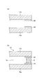
- FIG. 3 is a diagram showing a series of steps of the method for manufacturing the multilayer glass 10 according to the first embodiment of the present invention.
- FIG. 3A is a diagram showing an example of an adhesive application process.
- the adhesive 14 is applied to a predetermined region of the outer edge portion of the glass plate 1a.
- the same reference numerals are used without distinguishing the adhesive 14 and the adhesive layer 14.
- the method of applying the adhesive 14 is not particularly limited, and is performed by various application methods such as application by brush, application by cloth, application by a material having a solid shape such as felt, application by spray, application by dropping, and the like. Good.
- application using an impregnating material such as a brush, cloth, fault, etc.
- the adhesive 14 can be directly sprayed or dropped from above the glass plate 11a.
- the adhesive agent 14 can be apply
- region demonstrates and demonstrates the example which manufactures the multilayer glass 10 of FIG. 1, it becomes an area
- the application region can also be appropriately changed according to the application.
- the adhesive 14 is applied to a region narrower than the region where the spacer 12 ′ is formed. What is necessary is just to apply.
- region of the adhesive agent 14 can be variously changed according to a use.
- FIG. 3B is a diagram showing an example of the spacer bonding process.
- the spacer 12 is bonded onto the adhesive 14 applied to the glass plate 11a.
- the spacer 12 is formed from a thermoplastic resin material containing butyl rubber.
- the spacer 12 can be bonded in advance by molding the spacer 12 in advance using a resin material and pressing the molded spacer 12 onto the adhesive 14. At this time, the temperature of the spacer 12 is set to be 50 ° C. or higher and 160 ° C. or lower. That is, the spacer 12 once molded is bonded to the glass plate 11a in a molten state.
- the spacer 12 is heated to a high temperature such as 180 ° C.
- the spacer 12 is heated to 160 ° C. or less.
- the cooling time after bonding can be shortened, and the productivity can be increased.
- the spacer 12 is in a state of having a viscosity that can be easily molded, and can be easily molded into a predetermined shape.
- the spacer 12 is easily deformed and can be easily molded.
- the spacer 12 can be bonded in an easily molded state, and the cooling time after bonding can be shortened to increase productivity. be able to.
- butyl rubber is used as the material of the spacer 12.
- the butyl rubber includes two kinds of materials, a high molecular weight butyl rubber constituting a high molecular weight butyl rubber and a low molecular weight butyl rubber constituting a low molecular weight butyl rubber.
- the material having an average molecular weight of 55000 to 150,000 and the low molecular weight butyl rubber it is preferable to use a material having a number average molecular weight of 35000 to 50000. Thereby, the viscosity of a butyl-type rubber can be made low and the spacer 12 can be shape
- the spacer 12 is formed at a relatively low temperature of 50 ° C. or more and 160 ° C. or less. Can be adhered to the glass plate 11a.
- the spacer 12 may have any temperature as long as it is 50 ° C. or higher and 160 ° C. or lower, but is preferably 150 ° C. or lower, more preferably 130 ° C. or lower, still more preferably 120 ° C. or lower, and particularly preferably 110 ° C. or lower. This is because the lower the temperature, the less the deterioration of the spacer 12 and the shorter the cooling time of the spacer 12. Further, the temperature of the spacer 12 is preferably 60 ° C. or higher, and more preferably 70 ° C. or higher. This is because the spacer 12 is easily deformed and easily molded.
- the spacer 12 is adhered to the glass plate 11a 30 seconds to 20 minutes after the adhesive 14 is applied to the glass plate 11a. That is, since the adhesive 14 and the spacer 12 are mixed well by using the butyl rubber including the high molecular weight butyl rubber and the low molecular weight butyl rubber as the spacer 12, the adhesive 14 to be applied is Even if it is thin, good adhesion can be maintained. By thinning the adhesive 14 to be applied, the adhesive 14 is dried within 20 minutes, and the spacer 12 can be quickly bonded to the glass plate 11a. Thereby, production time can be shortened. Conventionally, since the application thickness of the adhesive was greater than 50 ⁇ m, it took 30 minutes or more from application to drying, and a large waiting time was generated here, making automation difficult.
- the spacer 12 can be adhered to the glass plate 11a 30 seconds to 20 minutes after the adhesive 14 is applied to the glass plate 11a. If the waiting time after applying the adhesive 14 to the glass plate 11a is about 30 seconds to 1 minute, the process can be automated and the multilayer glass 10 can be automatically manufactured.
- the thickness of the adhesive 14 is preferably 0.1 ⁇ m or more and 50 ⁇ m. As described above, by using butyl rubber having a low viscosity as the spacer 12, the adhesive 14 and the spacer 12 are mixed well, so that the thickness of the adhesive 14 can be reduced. As a result, the adhesive 14 dries in a short time of 30 seconds to 20 minutes, and the productivity can be improved.
- FIG. 3C is a diagram showing an example of the glass plate bonding step.
- another glass plate 11 b is bonded to the spacer 12.
- the glass plate 11b is bonded to the spacer 12 in a state where the adhesive 14 has already been applied to a predetermined region of the outer edge portion of the glass plate 11b.
- the same adhesive 14 as the adhesive 14 applied to the glass plate 11a may be used as the adhesive 14, and the application region where the adhesive 14 is applied is also the same as the application region of the glass plate 11a. It's okay.
- the timing of applying the adhesive 14 to the glass plate 11b may be the same as or different from the timing of applying the adhesive 14 to the glass plate 11a.
- the adhesive 14 may be applied to the glass plate 11a first, and the adhesive 14 may be applied to the glass plate 11b while performing the spacer bonding process.
- the glass plates 11a and 11b may be arranged side by side, and the adhesive 14 may be applied to the glass plates 11a and 11b almost simultaneously.
- coats the adhesive agent 14 to the glass plate 11b can be made into a suitable timing according to a use or application equipment.
- the glass plate 11b may be pressurized as necessary.
- pressure may be applied from above the glass plate 11b, or pressure may be applied from both sides of the glass plates 11a and 11b.
- the pressurization can ensure the adhesion between the glass plates 11a and 11b and the spacer 12, and the positions of the glass plates 11a and 11b and the spacer 12 can be fixed.
- the glass plate bonding step can be performed without heating after that. If the temperature of the spacer 12 is set to 50 ° C. or higher and 160 ° C. or lower at the stage of the spacer bonding process, the glass plate 11b can be bonded to the spacer 12 even if the temperature of the spacer 12 subsequently decreases. There is no problem in the process.
- FIG. 3 although the example which manufactures the multilayer glass 10 which consists of two glass plates 11a and 11b was given and demonstrated, the multilayer which consists of three sheets and four sheets and many glass plates 11a and 11b was demonstrated.
- a process of applying the adhesive 14 on the glass plate 11 b, bonding a new spacer 12, and further bonding a glass plate on the spacer 12 may be added. That is, the steps of FIGS. 3A to 3C may be repeated according to the number of the multi-layer glass 10.
- the adhesive agent 14 can be dried in a short time, and productivity can be improved.
- FIG. 4 is a view showing a series of steps of a method for producing a multilayer glass according to the second embodiment of the present invention.
- FIG. 4A is a diagram showing an example of the glass plate arranging step.
- the two glass plates 11a and 11b coated with the adhesive 14 are arranged to face each other. Naturally, it arrange
- coated may oppose.
- the adhesive application step described with reference to FIG. 3A is performed on each of the glass plates 11a and 11b. And the glass plates 11a and 11b which already apply
- FIG. 4B is a diagram showing an example of the spacer bonding process.
- the spacer 12 is formed by extruding a molten butyl rubber thermoplastic resin material by extrusion molding and filling between the two glass plates 11a and 11b facing each other.
- a butyl rubber containing a high molecular weight butyl rubber and a low molecular weight butyl rubber as a material for the spacer as described above, extrusion can be easily performed at a low temperature of about 100 to 150 ° C.
- a spacer bonding step can be performed.
- the glass plate 11b or the glass plates 11a and 11b may be pressurized as necessary.
- the method of pressurization is the same as that described with reference to FIG. 3C and can be applied as it is, so that the description thereof is omitted.
- the spacer adhesion process of FIG.4 (b) is a process which does not adhere the shape
- the multilayer glass which concerns on 2nd Embodiment, it has many more glass plates 11a and 11b, such as 3 sheets and 4 sheets, by repeating the process of Fig.4 (a) and (b).
- the production of the multi-layer glass 10 is possible. Since this point is the same as the content described in the first embodiment, the description thereof is omitted.
- the application region of the adhesive 14 and the adhesion region of the spacer 12 can be combined appropriately according to the application.
- FIG. 5 is a diagram showing a series of steps of the method for producing a multilayer glass according to the third embodiment of the present invention. Note that in the third embodiment, the same components as those in the first and second embodiments are denoted by the same reference numerals, and description thereof is omitted.
- FIG. 5A is a diagram showing an example of the glass plate adhesive application step.
- the adhesive 14 is applied to a predetermined region of the outer edge portion of the glass plate 11a. Since the adhesive application step is the same as that in FIG. 3A of the method for manufacturing a multilayer glass according to the first embodiment, the contents described in FIG. 3A can be applied as they are. Therefore, detailed description of the adhesive application process is omitted.
- FIG. 5B is a diagram showing an example of the spacer bonding step.
- the spacer 12 is bonded onto the adhesive 14 applied to the glass plate 11a. Since the spacer bonding step is the same as that in FIG. 3B of the method for manufacturing a multilayer glass according to the first embodiment, the contents described in FIG. 3B can be applied as they are. Therefore, detailed description of the spacer bonding step is omitted.
- FIG. 5C is a diagram showing an example of the spacer adhesive application process.
- the adhesive 14 is applied to the upper surface of the spacer 12, that is, the surface opposite to the surface bonded to the glass plate 11 a of the spacer 12 via the adhesive 14. That is, the adhesive 14 is applied to the surface of the spacer 12 on which the glass plate 11a is not bonded and parallel to the glass plate 11a.
- the adhesive 14 is applied to the glass plate 11b sandwiching the spacer 12, but the manufacturing method of the multilayer glass according to the third embodiment. Is different from the manufacturing method of the multilayer glass according to the first and second embodiments in that the adhesive 14 is applied to the spacer 12 instead of the glass plate 11b. As shown in FIG. 5C, the area of the spacer 12 is naturally smaller than that of the glass plate 11a. Therefore, the adhesive 14 is applied to the extent that the adhesive 14 does not overflow and flow out of the side surface of the spacer 12 according to the area of the spacer 12. Is done.
- the thickness of the adhesive 14 can be 0.1 ⁇ m or more and 50 ⁇ m, but is preferably set in the range of 20 to 30 ⁇ m, for example. Since the surface of the spacer 12 has a larger surface roughness than the surface of the glass plate 11b, the surface of the spacer 12 can serve as a buffer for the surface roughness by applying the adhesive 14 slightly thicker. A state can be made favorable. Thereby, the adhesion
- FIG. 5D is a diagram showing an example of the glass plate bonding step.
- the glass plate bonding step another glass plate 11b is bonded to the spacer 12 to which the adhesive 14 is applied.
- the adhesive 14 is not applied to the glass plate 11b, and the glass plate 11b is bonded to the spacer 12 in a state where the adhesive 14 is applied only to the spacer 12.
- the adhesive 14 may be applied to the spacer 12 to bond the second glass plate 11b.
- the multilayer glass 10 can be manufactured so that it may pile up sequentially from one side (lower side in FIG. 5), and workability
- coats the adhesive agent 14 separately to the glass plate 11b becomes unnecessary, space saving at the time of multilayer glass manufacture can be achieved.
- the area of the adhesive 14 for bonding the second glass plate 11b and the spacer 12 can be minimized, and the amount of the adhesive 14 used can be reduced.
- the adhesive 14 can be prevented from jumping out to unnecessary portions, and although it is the inner surface of the hollow layer 15, the aesthetics of the multilayer glass can be improved.
- the adhesive 14 can use the same adhesive 14 in the glass plate adhesive application process of Fig.5 (a), and the spacer adhesive application process of FIG.5 (c).
- the bonding objects are the glass plates 11a and 11b and the spacer 12, and are used for bonding the same kind of objects.
- the glass plate 11b may be pressurized as necessary in the glass plate bonding step.
- pressure may be applied from above the glass plate 11b, or pressure may be applied from both sides of the glass plates 11a and 11b.
- the pressurization can ensure the adhesion between the glass plates 11a and 11b and the spacer 12, and the positions of the glass plates 11a and 11b and the spacer 12 can be fixed.
- FIG. 5 although the example which manufactures the multi-layer glass 10 which consists of two glass plates 11a and 11b was given and demonstrated, the multi-layer glass 10 which consists of 3 sheets and 4 sheets and many glass plates is further demonstrated.
- the process of applying the adhesive 14 on the glass plate 11b, bonding a new spacer 12, applying the adhesive 14 on the spacer 12, and further bonding the glass plate is added. Good. That is, the steps of FIGS. 5A to 5D may be repeated according to the number of the multi-layer glass 10.
- a series of processes which consist of a glass plate adhesive application process, a spacer adhesion process, a spacer adhesive application process, and a glass plate adhesion process are applied. It can be performed by a similar operation as a base, and workability and productivity can be improved.
- thermoplastic resin composition constituting the spacer material is hydrophobic and the glass plates 1a and 1b are hydrophilic, it is required that the adhesiveness between the two can be ensured. It is possible to use any adhesive.
- a urethane-based adhesive made from a soft polyolefin-based polyol, a non-yellowing isocyanate, and a derivative of the non-yellowing isocyanate may be used.
- the urethane-based adhesive only needs to contain at least a polyol and an isocyanate, and may further contain a silane coupling agent as necessary in order to ensure adhesion with the glass plate.
- the polyol may be a polyester polyol or a polyacryl polyol in addition to the above-described soft polyolefin-based polyol, and may be a urethane resin obtained by reacting a polyol with an isocyanate.
- the isocyanate may be a non-yellowing isocyanate or a derivative of a non-yellowing isocyanate. Therefore, the urethane-based adhesive includes polyester polyol, polyacryl polyol, soft polyolefin-based polyol, and at least one urethane resin obtained by reacting polyol with non-yellowing isocyanate, non-yellowing isocyanate and non-yellowing isocyanate. And a silane coupling agent or the like as necessary.
- the polyol means a polyfunctional alcohol having one or more hydroxyl groups in one molecule.
- the polyol contained in the urethane-based adhesive preferably has a glass transition point Tg higher than 20 ° C.
- Tg glass transition point
- the molecular weight of the polyol is preferably in the range of 2000 to 50000.
- the acid value of the polyol is preferably less than 3 KOH mg / g.
- the acid value is the number of mg of potassium hydroxide required to neutralize free fatty acids present in 1 g of polyol, and indicates the degree of purification of the polyol, with the lower degree indicating higher degree of purification.
- a divalent hydrocarbon group having 4 carbon atoms is a repeating unit.
- a mixture of a compound capable of reacting with a terminal functional group of the oligomer and a terminal functional group of the oligomer, (B) a terminal reactive oligomer having a divalent hydrocarbon group having 4 carbon atoms as a repeating unit, and a terminal functional group of the oligomer It may be an adhesive composed of a combination of a reaction product of a compound capable of reacting with.
- the terminal reactive oligomer having a divalent hydrocarbon group having 4 carbon atoms as a repeating unit is an oligomer containing a repeating unit derived from a hydrocarbon monomer having 4 carbon atoms, and has a hydroxyl group at the end of the oligomer. It is a compound having a reactive functional group such as a carboxyl group, an amino group, a mercapto group, an epoxy group, or an isocyanate group. It is a compound that can become a high molecular weight polymer that functions as an adhesive by reacting a compound having a functional group capable of reacting with this functional group to cause chain extension or crosslinking.
- the lower limit of the molecular weight of the terminal reactive oligomer is not particularly limited, but is usually about 2000.
- the upper limit is not particularly limited, but is about 10,000.
- the molecular weight is preferably from 500 to 10,000, particularly preferably from 1,000 to 5,000.
- the terminal reactive oligomer is preferably a substantially linear oligomer.
- the relatively low molecular weight oligomer may be a branched oligomer, or may be a trifunctional or higher functional oligomer having a branch having a reactive functional group at each end.
- Preferred end-reactive oligomers in the multilayer glass according to the embodiment of the present invention are 1-butene homopolymer, isoprene homopolymer, 1-butene-isoprene copolymer, butadiene homopolymer (1 , 2-polybutadiene and 1,4-polybutadiene), and copolymers of at least one monomer having 4 carbon atoms such as 1-butene, isoprene, and butadiene with isoprene, pentadiene, styrene, and the like. Hydride.
- the most preferred terminal reactive oligomer is a butadiene homopolymer hydride.
- Examples of the functional group in the terminal reactive oligomer include a hydroxyl group, a carboxyl group, an amino group, a mercapto group, an epoxy group, and an isocyanate group.
- a hydroxyl group or a carboxyl group is preferred, and a hydroxyl group is particularly preferred.
- the compound capable of reacting with the terminal functional group of the oligomer a compound having two or more functional groups capable of reacting with the functional group of the terminal reactive oligomer is used.
- a hydroxyl-terminated oligomer can be reacted with a polyisocyanate to form a polyurethane, and can be reacted with a polycarboxylic acid or its acid chloride or alkyl ester to form a polyester.
- carboxyl group-terminated oligomers can be reacted with polyols, polyamines, polyepoxides, etc., and amino group-terminated oligomers can be reacted with polyepoxides, polycarboxylic acids or anhydrides thereof.
- a particularly preferred combination of the terminal reactive oligomer and the compound capable of reacting with the terminal functional group of the oligomer in the multilayer glass according to the embodiment of the present invention is a hydroxyl group terminal oligomer and a polyisocyanate or polycarboxylic acid or a reactive acid derivative thereof. It is a combination with the compound which becomes.
- silane coupling agent can be added to the above-described adhesive as necessary. As described above, the silane coupling agent is used to increase the adhesion with glass.
- silane coupling agent examples include epoxy silanes such as 3-glycidoxypropyltrimethoxysilane and 3-glycidoxypropyltriethoxysilane, 3-aminopropyltrimethoxysilane, 3-aminopropylethoxysilane, 3 And aminosilanes such as -triethoxysilyl-N- (1,3-dimethyl-butylidene) propylamine.
- an additive such as an antioxidant, a wetting agent, an antifoaming agent, and an organic solvent may be added to the above-described adhesive as necessary.
- Table 1 shows the compositions of the adhesive solutions 1 to 3 prepared in this example.
- Adhesive solutions 1 to 3 shown in Table 1 were prepared as follows.
- a urethane resin solution having a solid content concentration of about 50 wt%, 1.13 parts by mass of hexamethylene diisocyanate, 0.5 parts by mass of 3-aminopropyltrimethoxysilane, toluene and methyl ethyl ketone, etc.
- the amount of the mixed solvent was changed to 61.3 parts by mass and 0 parts by mass to obtain adhesives 2 and 3, respectively.
- solid content concentration was 10%, 1%, and 50% with adhesives 1, 2, and 3, respectively.
- Table 2 shows the compositions of the adhesive solutions 4 to 7 prepared in this example.
- Table 3 shows specific types and characteristics of the polyols of the adhesive solutions 4 to 7 shown in Table 2.
- Table 4 shows the compositions of the spacers A, B, and C used in this example.
- each numerical value indicates a mass ratio with respect to 100 parts by mass.
- butyl rubber having a number average molecular weight of 76000 on the low molecular weight side was used in the range of a number average molecular weight of 55,000 or more, which shows the physical properties (elastomer characteristics, rubbery elasticity) of the high molecular weight butyl rubber.
- the spacer A has a mass ratio of 18.0 parts by mass, and the spacer B has a mass ratio of 21.3 parts by mass.
- the polyisobutylene used was a polyisobutylene having a number average molecular weight of 41,000 on the high molecular weight side in the range of a number average molecular weight of 50000 or less indicating the physical properties (adhesiveness) of the low molecular weight butyl rubber.
- the spacer A has a mass ratio of 18.0 parts by mass, and the spacer B has a mass ratio of 21.3 parts by mass.
- a size exclusion chromatography apparatus manufactured by Tosoh Corporation (main body: HLC-8220GPC, RI detector, guard column: TSKgen guardcolumn SuperHZ-L, column: TSKgen SuperHZ2000, TSKgel) SuperHZ2500, TSKgel SuperHZ4000) were used, and measurement was performed with reference to a THF solvent and a polystyrene standard sample.
- HDPE indicates a high-density polyethylene having a melt flow rate MFR of 20 g / 10 minutes (according to JIS K6922-2) and a melting point of 133 ° C. It is not contained in the spacer A, and the spacer B has a mass ratio of 4.3 parts by mass. Further, the modified PE indicates polyethylene having a melt flow rate MFR of 80 g / 10 min (according to JIS K6922-2), a melting point of 98 ° C., and an acid anhydride and an acrylate ester introduced thereinto. The spacer A has a mass ratio of 6.0 parts by mass, and the spacer B is not contained.
- the tackifier was a DCPD (dicyclopentadiene) type hydrogenated hydrocarbon resin having a softening point of 125 ° C.
- Spacer A has a mass ratio of 10.7 parts by mass
- spacer B has a mass ratio of 10.6 parts by mass.
- Talc and carbon black are inorganic fillers.
- the inorganic filler an inorganic filler containing talc having an average particle diameter of 2 ⁇ m and HAF (High Abrasion® Furnace) type carbon black was used. Each of them is contained in the spacers A and B and contained in parts by mass shown in Table 2.
- FIG. 6 is a view showing the structure of an adhesive evaluation sample for evaluating the adhesiveness of Examples 1 to 12 and Comparative Examples 1 to 3.
- An adhesive evaluation sample in which the adhesive 14s was applied to the surfaces of the glass plates 11c and 11d and the spacer 12s was adhered was produced, and the adhesiveness of Examples 1 to 12 and Comparative Examples 1 to 3 was evaluated.
- FIG. 7 is a table showing combination configurations and evaluation results of Examples 1 to 12.
- FIG. 8 is a table showing the combined configurations and evaluation results of Comparative Examples 1 to 3.
- Example 1 was produced as follows. Two float glasses of 50 mm x 50 mm and 5 mm thickness are washed with ethanol, and the adhesive 1 is soaked in the felt so that it becomes 10 mm wide at the center of the glass. After 1 minute, it is heated to 60 ° C in advance. The spacer A having a width of 7 mm, a thickness of 12 mm, and a length of 50 mm was disposed on the adhesive 1. Furthermore, the glass coated with the adhesive 1 in the same manner was combined and pressed at a pressure of 0.1 MPa for 1 minute to obtain a sample of Example 1 as shown in FIG.
- Example 2 Samples of Examples 3 to 6 and Comparative Examples 2 and 3 were produced in the same manner as Example 1.
- the adhesive 2 was used.
- Example 7 spacer B was used.
- Example 8 the adhesive 3 was used.
- Example 9 the adhesive 4 and the spacer C were used.
- Example 10 the adhesive 5 and the spacer C were used.
- Example 11 the adhesive 6 and the spacer C were used.
- Example 12 the adhesive 7 and the spacer C were used.
- no adhesive was used.
- the spacer temperature during bonding was also changed.
- the spacer temperature was changed in the range of 60 to 150 ° C.
- Comparative Examples 2 and 3 the temperature was set to 40 ° C. below the lower limit and 180 ° C. above the upper limit.
- the dew point measurement sample used in the dew point measurement at the second stage from the bottom of FIGS. 7 and 8 is obtained by washing two float glasses of 350 mm ⁇ 500 mm and a thickness of 5 mm with hot water so that the peripheral part of the glass becomes 10 mm wide.
- the adhesive 1 was apply
- the dew point measurement samples of Examples 2 to 12 and Comparative Examples 2 and 3 were obtained by changing the adhesive.
- an acceleration measurement sample used in the accelerated durability test at the bottom of FIGS. 7 and 8 was produced as follows. After obtaining the dew point measurement sample, a spacer A having a width of 7 mm and a thickness of 6 mm, which had been heated to 60 ° C. in advance, was placed on one glass outer edge. Furthermore, another glass was combined thereon and pressed at a pressure of 0.1 MPa for 5 minutes to obtain a multilayer glass of Example 1. Similarly, the types of adhesives, the types of spacers, and the spacer temperature during bonding were changed to obtain the multilayer glasses of Examples 2 to 12 and Comparative Examples 1 to 3.
- the initial plate displacement of the fourth stage from the bottom is adhesive 1 so that two float glasses of 500 mm ⁇ 1000 mm and thickness 5 mm are washed with warm water and the width of the glass is 10 mm around the periphery.
- a spacer A having a width of 7 mm and a thickness of 12 mm preliminarily heated to 140 ° C. was arranged on one glass periphery, and the adhesive 1 was applied to the spacer A.
- another glass was put thereon and pressed at a pressure of 0.1 MPa for 20 seconds to obtain a multilayer glass (Example 1).
- the laminated glass of Examples 2 to 12 and Comparative Examples 1 to 3 was obtained by changing the type of adhesive, the type of spacer, and the spacer temperature during bonding.
- the adhesive film thickness in the fourth step from the top was applied to a 50 mm ⁇ 50 mm, 5 mm thick float glass, and the solvent was dried. Thereafter, the coating thickness of the adhesive was measured with a 3D measurement laser microscope (LEXT OLS4000, manufactured by OLYMPUS Corporation).
- the air drying time at the fifth stage from the top is defined as the air drying time when the adhesive solution was applied to 50 mm ⁇ 50 mm and 5 mm thick float glass and the solvent odor disappeared at room temperature. An air drying time of 20 minutes or less was accepted, and when it exceeded 20 minutes, it was rejected.
- the third stage from the bottom after preparing the sample shown in FIG. 5, leave the sample for 2 days at room temperature, and further immersed in warm water at 60 ° C. for 6 days. It was taken out and dried at room temperature for 1 day. The dried sample was subjected to an adhesion test using an autograph (ORIENTIC RTC-1210) and pulling the glass in both directions at a speed of 50 mm / min. As the determination, a maximum point stress of 25 N / cm 2 or more was accepted and less than 25 N / cm 2 was rejected.
- the dew point was measured according to the apparatus and method described in JIS R3209. As a judgment, as described in JIS R3209 item 4.2, less than ⁇ 35 ° was accepted and ⁇ 35 ° or more was rejected.
- the accelerated durability test at the lowermost stage was tested in accordance with JIS R3209 on a multilayer glass having a float glass of 350 mm ⁇ 500 mm, a thickness of 5 mm and a spacer of 6 mm in thickness. As the determination, the determination was made according to the description of the class III determination described in item 3b) of JIS R3209.
- the temperature of the spacer at the time of adhesion was set to 60 ° C. to 150 ° C. within the range of 50 ° C. or more and 160 ° C. or less.
- the film thickness was 2.3 ⁇ m or less, and a thin adhesive layer was obtained.
- the air drying time was 1 minute or less.
- the adhesive also is 26N / cm 2 or more, exceeding the 25 N / cm 2 or more acceptance criteria.
- the dew point was also -60 ° C, which was less than -35 ° C.
- the accelerated durability test was also passed. Furthermore, the initial misalignment test was also passed.
- Example 8 a sample was obtained using the adhesive 3 at a spacer temperature of 80 ° C. during bonding.
- the film thickness of the adhesive was 50 ⁇ m or more and the air drying time was 30 minutes or more. Only this point did not clear the standard, but all other evaluation items passed, and the dew point measurement test and accelerated durability test, which are JIS standards Also passed. Therefore, when the requirement of the air drying time is not high, Example 8 is also included in the usable range.
Abstract
Description
前記複数枚のガラス板の少なくとも1枚に接着剤を塗布する工程と、
前記スペーサーを50℃以上160℃以下の温度で前記接着剤が塗布された前記ガラス板に接着させる工程と、を有し、
前記スペーサーは、ブチル系ゴムを含む熱可塑性樹脂材料から形成されてなることを特徴とする。 In order to achieve the above object, a method for producing a multilayer glass according to an aspect of the present invention includes a multilayer in which a plurality of glass plates are arranged to face each other via a spacer, and a hollow layer is formed between the glass plates. A method for producing glass,
Applying an adhesive to at least one of the plurality of glass plates;
Adhering the spacer to the glass plate coated with the adhesive at a temperature of 50 ° C. or more and 160 ° C. or less,
The spacer is formed of a thermoplastic resin material containing butyl rubber.
以下、本発明の実施例について説明する。なお、以下にいう「幅」は例えば図1の左右方向の寸法に相当する。また、「厚み方向」は例えば図1の上下方向に相当し、「厚さ」は例えば図1の上下方向の寸法に相当する。 [Example]
Examples of the present invention will be described below. The “width” described below corresponds to, for example, the horizontal dimension in FIG. Further, the “thickness direction” corresponds to, for example, the vertical direction in FIG. 1, and the “thickness” corresponds to, for example, the vertical dimension in FIG.
表1は、本実施例において作製した接着剤溶液1~3の組成を示している。 (Example of adhesive)
Table 1 shows the compositions of the


表4は、本実施例で用いたスペーサーA、B、Cの組成を示している。 (Example of spacer)
Table 4 shows the compositions of the spacers A, B, and C used in this example.

図6は、実施例1~12及び比較例1~3の接着性を評価するための接着性評価サンプルの構成を示した図である。ガラス板11c、11dの表面に接着剤14sが塗布され、スペーサー12sが接着された接着性評価サンプルを作製し、実施例1~12及び比較例1~3の接着性の評価を行った。 (Examples and evaluation results)
FIG. 6 is a view showing the structure of an adhesive evaluation sample for evaluating the adhesiveness of Examples 1 to 12 and Comparative Examples 1 to 3. An adhesive evaluation sample in which the adhesive 14s was applied to the surfaces of the
11a、11b、11c、11d ガラス板
12、12’、12s スペーサー
14、14s 接着剤層
15 中空層 10, 10 '
Claims (18)
- 複数枚のガラス板がスペーサーを介して対向配置され、前記ガラス板間に中空層が形成されてなる複層ガラスの製造方法であって、
前記複数枚のガラス板の少なくとも1枚に接着剤を塗布する工程と、
前記スペーサーを50℃以上160℃以下の温度で前記ガラス板に接着させる工程と、を有し、
前記スペーサーは、ブチル系ゴムを含む熱可塑性樹脂材料から形成されてなる複層ガラスの製造方法。 A method for producing a multi-layer glass in which a plurality of glass plates are arranged to face each other with a spacer, and a hollow layer is formed between the glass plates,
Applying an adhesive to at least one of the plurality of glass plates;
Adhering the spacer to the glass plate at a temperature of 50 ° C. or more and 160 ° C. or less,
The said spacer is a manufacturing method of the multilayer glass formed from the thermoplastic resin material containing a butyl-type rubber. - 前記複数枚のガラス板の少なくとも1枚に前記接着剤を塗布する工程は、
第1のガラス板に前記接着剤を塗布する工程と、
第2のガラス板に前記接着剤を塗布する工程と、を含み、
前記スペーサーを前記ガラス板に接着させる工程は、
前記第1のガラス板に前記スペーサーを接着させる工程と、
前記第1のガラス板に接着した前記スペーサーに第2のガラス板を接着させる工程と、を含む請求項1に記載の複層ガラスの製造方法。 Applying the adhesive to at least one of the plurality of glass plates,
Applying the adhesive to the first glass plate;
Applying the adhesive to the second glass plate,
The step of bonding the spacer to the glass plate includes:
Adhering the spacer to the first glass plate;
The method for producing a multilayer glass according to claim 1, comprising a step of adhering a second glass plate to the spacer adhered to the first glass plate. - 前記第2のガラス板に前記接着剤を塗布する工程は、前記第1のガラス板に前記スペーサーを接着させる工程より前に行われる請求項2に記載の複層ガラスの製造方法。 The method for producing a multilayer glass according to claim 2, wherein the step of applying the adhesive to the second glass plate is performed before the step of bonding the spacer to the first glass plate.
- 前記第2のガラス板に前記接着剤を塗布する工程は、前記第1のガラス板に前記スペーサーを接着させる工程の後に行われる請求項2に記載の複層ガラスの製造方法。 The method for producing a multilayer glass according to claim 2, wherein the step of applying the adhesive to the second glass plate is performed after the step of bonding the spacer to the first glass plate.
- 前記第2のガラス板を接着させる工程は、前記第2のガラス板を加圧しながら行う請求項2乃至4のいずれか一項に記載の複層ガラスの製造方法。 The method for producing a multilayer glass according to any one of claims 2 to 4, wherein the step of bonding the second glass plate is performed while pressurizing the second glass plate.
- 前記スペーサーを前記ガラス板に接着させる工程は、2枚のガラス板を対向させた状態で、対向する前記2枚のガラス板の間に前記スペーサーを供給する工程である請求項1に記載の複層ガラスの製造方法。 2. The multilayer glass according to claim 1, wherein the step of bonding the spacer to the glass plate is a step of supplying the spacer between the two glass plates facing each other with the two glass plates facing each other. Manufacturing method.
- 前記スペーサーを供給する工程の後、前記2枚のガラス板を加圧する工程を更に有する請求項6に記載の複層ガラスの製造方法。 The method for producing a multilayer glass according to claim 6, further comprising a step of pressurizing the two glass plates after the step of supplying the spacer.
- 前記2枚のガラス板を加圧する工程は、前記スペーサーを加熱しながら行う請求項7に記載の複層ガラスの製造方法。 The method for producing a multilayer glass according to claim 7, wherein the step of pressurizing the two glass plates is performed while heating the spacer.
- 前記複数枚のガラス板の少なくとも1枚に前記接着剤を塗布する工程は、第1のガラス板のみに前記接着剤を塗布する工程であり、
前記スペーサーを前記ガラス板に接着させる工程は、第1のガラス板に前記スペーサーを接着させる工程であり、
前記スペーサーの前記第1のガラス板と反対面に前記接着剤を塗布する工程と、
前記スペーサーの前記接着剤を塗布した前記第1のガラス板と反対面に第2のガラス板を接着させる工程と、を更に有する請求項1に記載の複層ガラスの製造方法。 The step of applying the adhesive to at least one of the plurality of glass plates is a step of applying the adhesive only to the first glass plate,
The step of bonding the spacer to the glass plate is a step of bonding the spacer to the first glass plate,
Applying the adhesive to the surface of the spacer opposite to the first glass plate;
The method for producing a multilayer glass according to claim 1, further comprising a step of adhering a second glass plate to a surface opposite to the first glass plate to which the adhesive of the spacer is applied. - 前記ブチル系ゴムは、高分子量ブチル系ゴムと低分子量ブチル系ゴムとを含み、
前記高分子量ブチル系ゴムの数平均分子量は55000以上150000以下であり、
前記低分子量ブチル系ゴムの数平均分子量は35000以上50000以下である請求項1乃至9のいずれか一項に記載の複層ガラスの製造方法。 The butyl rubber includes a high molecular weight butyl rubber and a low molecular weight butyl rubber,
The number average molecular weight of the high molecular weight butyl rubber is 55000 or more and 150,000 or less,
The number average molecular weight of the said low molecular weight butyl-type rubber is 35000 or more and 50000 or less, The manufacturing method of the multilayer glass as described in any one of Claim 1 thru | or 9. - 前記複数枚のガラス板の少なくとも1枚に前記接着剤を塗布する工程の後、30秒~20分後に前記スペーサーを前記ガラス板に接着させる工程を行う請求項1乃至9いずれか一項に記載の複層ガラスの製造方法。 10. The step of adhering the spacer to the glass plate after 30 seconds to 20 minutes after the step of applying the adhesive to at least one of the plurality of glass plates. A method for producing a multilayer glass.
- 前記接着剤の厚さが0.1μm以上50μm以下である請求項1乃至11のいずれか一項に記載の複層ガラスの製造方法。 The method for producing a multilayer glass according to any one of claims 1 to 11, wherein a thickness of the adhesive is 0.1 µm or more and 50 µm or less.
- 前記接着剤は、ウレタン系接着剤である請求項1乃至12のいずれか一項に記載された複層ガラスの製造方法。 The method for producing a multi-layer glass according to any one of claims 1 to 12, wherein the adhesive is a urethane-based adhesive.
- 前記ウレタン系接着剤は、軟質ポリオレフィン系ポリオール、ポリエステルポリオール、ポリアクリルポリオール及び、ポリオールと無黄変イソシアネートとを反応させたウレタン樹脂の少なくとも1つを含むとともに、無黄変イソシアネート及び該無黄変イソシアネートの誘導体の少なくとも1つを含む、請求項13に記載の複層ガラスの製造方法。 The urethane-based adhesive includes at least one of a soft polyolefin-based polyol, a polyester polyol, a polyacryl polyol, and a urethane resin obtained by reacting a polyol with a non-yellowing isocyanate, and includes a non-yellowing isocyanate and the non-yellowing The method for producing a multilayer glass according to claim 13, comprising at least one derivative of isocyanate.
- 前記ウレタン系接着剤に含まれている前記ポリエステルポリオール又はポリアクリルポリオールは、ガラス転移点が20℃よりも大きい請求項14に記載の複層ガラスの製造方法。 The method for producing a multilayer glass according to claim 14, wherein the polyester polyol or polyacryl polyol contained in the urethane-based adhesive has a glass transition point higher than 20 ° C.
- 複数枚のガラス板がスペーサーを介して対向配置され、前記ガラス板間に中空層が形成されてなる複層ガラスであって、
前記スペーサーと前記ガラス板とは接着剤を介して接着されており、
前記接着剤の厚さは0.1μm以上50μm以下であり、
前記スペーサーは、ブチル系ゴムを含む熱可塑性樹脂材料から形成されてなる複層ガラス。 A plurality of glass plates are arranged opposite to each other with a spacer, and a multilayer glass in which a hollow layer is formed between the glass plates,
The spacer and the glass plate are bonded via an adhesive,
The adhesive has a thickness of 0.1 μm or more and 50 μm or less,
The spacer is a multi-layer glass formed of a thermoplastic resin material containing butyl rubber. - 前記ブチル系ゴムは、高分子量ブチル系ゴムと低分子量ブチル系ゴムとを含み、
前記高分子量ブチル系ゴムの数平均分子量は55000以上150000以下であり、
前記低分子量ブチル系ゴムの数平均分子量は35000以上50000以下である請求項16に記載の複層ガラス。 The butyl rubber includes a high molecular weight butyl rubber and a low molecular weight butyl rubber,
The number average molecular weight of the high molecular weight butyl rubber is 55000 or more and 150,000 or less,
The number average molecular weight of the said low molecular weight butyl-type rubber is 35000 or more and 50000 or less, The multilayer glass of Claim 16. - 前記スペーサーと前記ガラス板との間にシール材が設けられた請求項16又は17に記載の複層ガラス。 The multilayer glass according to claim 16 or 17, wherein a sealing material is provided between the spacer and the glass plate.
Priority Applications (3)
| Application Number | Priority Date | Filing Date | Title |
|---|---|---|---|
| EP18789832.5A EP3617168B1 (en) | 2017-04-28 | 2018-04-25 | Method of manufacturing insulating glass and insulating glass |
| JP2019514584A JP7120223B2 (en) | 2017-04-28 | 2018-04-25 | Multi-layered glass manufacturing method and double-layered glass |
| EP23180412.1A EP4234653A3 (en) | 2017-04-28 | 2018-04-25 | Multi-layered glass manufacturing method and multi-layered glass |
Applications Claiming Priority (2)
| Application Number | Priority Date | Filing Date | Title |
|---|---|---|---|
| JP2017090610 | 2017-04-28 | ||
| JP2017-090610 | 2017-04-28 |
Publications (1)
| Publication Number | Publication Date |
|---|---|
| WO2018199178A1 true WO2018199178A1 (en) | 2018-11-01 |
Family
ID=63918502
Family Applications (1)
| Application Number | Title | Priority Date | Filing Date |
|---|---|---|---|
| PCT/JP2018/016849 WO2018199178A1 (en) | 2017-04-28 | 2018-04-25 | Multi-layered glass manufacturing method and multi-layered glass |
Country Status (3)
| Country | Link |
|---|---|
| EP (2) | EP4234653A3 (en) |
| JP (1) | JP7120223B2 (en) |
| WO (1) | WO2018199178A1 (en) |
Citations (4)
| Publication number | Priority date | Publication date | Assignee | Title |
|---|---|---|---|---|
| JPH10114551A (en) * | 1995-12-26 | 1998-05-06 | Asahi Glass Co Ltd | Plural-layer glass |
| WO1998030649A1 (en) * | 1997-01-14 | 1998-07-16 | Asahi Glass Company Ltd. | Adhesive for glass |
| JPH10238235A (en) | 1997-02-26 | 1998-09-08 | Asahi Glass Co Ltd | Plural-layer glass |
| JP2017090610A (en) | 2015-11-09 | 2017-05-25 | キヤノン株式会社 | Lens device and image taking device having the lens device |
Family Cites Families (2)
| Publication number | Priority date | Publication date | Assignee | Title |
|---|---|---|---|---|
| US6235356B1 (en) * | 1995-12-26 | 2001-05-22 | Asahi Glass Company Ltd. | Resin composition for building materials and insulating glass |
| BR9913687A (en) * | 1998-08-19 | 2001-06-05 | Cordant Tech Inc | Ablative rocket assembly materials formed from, as a precursor, textile cellulosic fibers, and method for the insulation or thermal protection of a rocket assembly with the same |
-
2018
- 2018-04-25 EP EP23180412.1A patent/EP4234653A3/en active Pending
- 2018-04-25 JP JP2019514584A patent/JP7120223B2/en active Active
- 2018-04-25 EP EP18789832.5A patent/EP3617168B1/en active Active
- 2018-04-25 WO PCT/JP2018/016849 patent/WO2018199178A1/en active Application Filing
Patent Citations (4)
| Publication number | Priority date | Publication date | Assignee | Title |
|---|---|---|---|---|
| JPH10114551A (en) * | 1995-12-26 | 1998-05-06 | Asahi Glass Co Ltd | Plural-layer glass |
| WO1998030649A1 (en) * | 1997-01-14 | 1998-07-16 | Asahi Glass Company Ltd. | Adhesive for glass |
| JPH10238235A (en) | 1997-02-26 | 1998-09-08 | Asahi Glass Co Ltd | Plural-layer glass |
| JP2017090610A (en) | 2015-11-09 | 2017-05-25 | キヤノン株式会社 | Lens device and image taking device having the lens device |
Also Published As
| Publication number | Publication date |
|---|---|
| EP3617168B1 (en) | 2024-03-27 |
| EP3617168A4 (en) | 2021-01-13 |
| EP3617168A1 (en) | 2020-03-04 |
| EP4234653A2 (en) | 2023-08-30 |
| EP4234653A3 (en) | 2023-10-04 |
| JPWO2018199178A1 (en) | 2020-03-19 |
| JP7120223B2 (en) | 2022-08-17 |
Similar Documents
| Publication | Publication Date | Title |
|---|---|---|
| CN110423592B (en) | Double-component polyurethane adhesive and preparation method thereof | |
| US9574120B2 (en) | Structural adhesive sheet specifically for use in a mirror base of an automobile interior rear-view mirror and a method for producing the same | |
| JP6509492B2 (en) | Moisture-curable hot melt adhesive for lamps | |
| CN113736417B (en) | Polyether ester type polyurethane hot melt adhesive with good heat resistance and preparation method thereof | |
| KR100910184B1 (en) | Synthetic method of methacryl terminated polyurethane and UV curable waterproofing adhesive using the synthetic polyurethane for electronic device protection | |
| CN108977155A (en) | Wet-curing reaction type polyurethane hot melt adhesives composition and preparation method thereof | |
| CN113845873B (en) | Bio-polyether ester reaction type polyurethane hot melt adhesive and preparation method thereof | |
| JP2018535286A (en) | Curable and optically transparent pressure sensitive adhesive and use thereof | |
| KR101269196B1 (en) | A self-adhesive protection film having improved properties and an article attached with the same | |
| CN102642353A (en) | Optical film sticking structure and manufacturing method thereof | |
| JPWO2018179178A1 (en) | Two-part curable urethane composition | |
| CN113861852A (en) | Single-component moisture curing reaction type polyurethane hot melt adhesive for electronic products and preparation method thereof | |
| WO2018199177A1 (en) | Double-glazed glass and method for producing same, and sealing material for double-glazed glasses | |
| WO2018199178A1 (en) | Multi-layered glass manufacturing method and multi-layered glass | |
| CN113736416A (en) | Bio-based reactive polyurethane hot melt adhesive and preparation method thereof | |
| JP2008105416A (en) | Composite body of glass and hot melt composition and its manufacturing method | |
| KR20170014090A (en) | Adhesive composition for decoration sheet, adhesive sheet and decoration panel | |
| CN111675999A (en) | Photocurable adhesive layer composition and protective film thereof | |
| WO2021006187A1 (en) | Isocyanate-based adhesive | |
| WO2019138893A1 (en) | Moisture-curable hot-melt adhesive and bonded article | |
| KR20170079713A (en) | Adhesive composition, Display device comprising the same and Method of making display device using the same | |
| JP2011526551A (en) | Method for manufacturing suction pad with adhesive resin attached | |
| CN114276777A (en) | Reactive polyurethane hot melt adhesive and preparation method thereof | |
| WO2024048279A1 (en) | Multiple glazing, production method therefor, and sealing material for multiple glazing | |
| KR20210018664A (en) | Manufacturing mehtod of interior materials and interior materials |
Legal Events
| Date | Code | Title | Description |
|---|---|---|---|
| 121 | Ep: the epo has been informed by wipo that ep was designated in this application |
Ref document number: 18789832 Country of ref document: EP Kind code of ref document: A1 |
|
| ENP | Entry into the national phase |
Ref document number: 2019514584 Country of ref document: JP Kind code of ref document: A |
|
| NENP | Non-entry into the national phase |
Ref country code: DE |
|
| WWE | Wipo information: entry into national phase |
Ref document number: 2018789832 Country of ref document: EP |
|
| ENP | Entry into the national phase |
Ref document number: 2018789832 Country of ref document: EP Effective date: 20191128 |