WO2018198499A1 - 情報処理装置、情報処理方法、及び記録媒体 - Google Patents
情報処理装置、情報処理方法、及び記録媒体 Download PDFInfo
- Publication number
- WO2018198499A1 WO2018198499A1 PCT/JP2018/006020 JP2018006020W WO2018198499A1 WO 2018198499 A1 WO2018198499 A1 WO 2018198499A1 JP 2018006020 W JP2018006020 W JP 2018006020W WO 2018198499 A1 WO2018198499 A1 WO 2018198499A1
- Authority
- WO
- WIPO (PCT)
- Prior art keywords
- imaging unit
- unit
- information processing
- input
- processing apparatus
- Prior art date
Links
Images


Classifications
-
- G—PHYSICS
- G06—COMPUTING; CALCULATING OR COUNTING
- G06F—ELECTRIC DIGITAL DATA PROCESSING
- G06F3/00—Input arrangements for transferring data to be processed into a form capable of being handled by the computer; Output arrangements for transferring data from processing unit to output unit, e.g. interface arrangements
- G06F3/01—Input arrangements or combined input and output arrangements for interaction between user and computer
- G06F3/017—Gesture based interaction, e.g. based on a set of recognized hand gestures
-
- G—PHYSICS
- G06—COMPUTING; CALCULATING OR COUNTING
- G06F—ELECTRIC DIGITAL DATA PROCESSING
- G06F3/00—Input arrangements for transferring data to be processed into a form capable of being handled by the computer; Output arrangements for transferring data from processing unit to output unit, e.g. interface arrangements
- G06F3/01—Input arrangements or combined input and output arrangements for interaction between user and computer
- G06F3/03—Arrangements for converting the position or the displacement of a member into a coded form
- G06F3/0304—Detection arrangements using opto-electronic means
-
- G—PHYSICS
- G06—COMPUTING; CALCULATING OR COUNTING
- G06F—ELECTRIC DIGITAL DATA PROCESSING
- G06F3/00—Input arrangements for transferring data to be processed into a form capable of being handled by the computer; Output arrangements for transferring data from processing unit to output unit, e.g. interface arrangements
- G06F3/01—Input arrangements or combined input and output arrangements for interaction between user and computer
- G06F3/048—Interaction techniques based on graphical user interfaces [GUI]
- G06F3/0487—Interaction techniques based on graphical user interfaces [GUI] using specific features provided by the input device, e.g. functions controlled by the rotation of a mouse with dual sensing arrangements, or of the nature of the input device, e.g. tap gestures based on pressure sensed by a digitiser
Definitions
- the present disclosure relates to an information processing apparatus, an information processing method, and a recording medium.
- so-called information processing devices In recent years, with the advancement of communication technology and the miniaturization of various devices, the type of equipment called so-called information processing devices has also diversified, not limited to PCs (Personal Computers) etc., like smartphones and tablet terminals, Information processing apparatuses configured to be carried by users are also becoming popular.
- a so-called wearable device has also been proposed that is configured to be used while being carried by a user wearing it on a part of the body.
- a wearable device a device (hereinafter referred to as a “head-mounted device”) used by being worn on the head, such as an HMD (Head Mounted Display) or glasses-type wearable device.
- HMD Head Mounted Display
- glasses-type wearable device For example.
- input devices such as buttons, switches, touch sensors, and the like are generally known as examples of an input interface for a user to input various types of information to the information processing apparatus.
- an input interface for a user to input various types of information to the information processing apparatus.
- a head-mounted device it may be difficult for a user to directly view an input device provided in a part of the housing due to the characteristic of being mounted on the head and used. Usability is poor compared to the case where the input interface is visible.
- gesture input may be adopted as an input interface for inputting various information to the information processing apparatus without using an input device such as a button or a switch.
- gesture input requires processing with a relatively high load such as image recognition, the power consumption tends to increase.
- an information processing apparatus capable of recognizing a user's operation input in a more preferable manner without using an input device provided in a housing of the apparatus. suggest.
- the information processing apparatus includes: a determination unit that determines whether or not the imaging unit is in a predetermined shielding state; and a recognition unit that recognizes a user operation input according to the predetermined shielding state. Is provided.
- the computer includes determining whether the imaging unit is in a predetermined shielding state, and recognizing a user operation input according to the predetermined shielding state. An information processing method is provided.
- the computer is caused to determine whether or not the imaging unit is in a predetermined shielding state and to recognize a user's operation input according to the predetermined shielding state.
- a recording medium on which the program is recorded is provided.
- FIG. 3 is an explanatory diagram for describing an example of a schematic configuration of an input / output device according to the embodiment. It is explanatory drawing for demonstrating the outline
- FIG. 10 is an explanatory diagram for describing an example of a user interface according to Modification 1.
- FIG. 10 is an explanatory diagram for describing an example of a user interface according to Modification 2.
- FIG. 3 is a functional block diagram illustrating a configuration example of a hardware configuration of an information processing apparatus configuring an information processing system according to an embodiment of the present disclosure.
- FIG. 1 is an explanatory diagram for explaining an example of a schematic configuration of an information processing system according to an embodiment of the present disclosure, and applies various contents to a user by applying a so-called AR (Augmented Reality) technique. An example in the case of presenting is shown.
- AR Augmented Reality
- reference numeral m111 schematically shows an object (for example, a real object) located in the real space.
- Reference numerals v131 and v133 schematically indicate virtual contents (for example, virtual objects) presented so as to be superimposed on the real space. That is, the information processing system 1 according to the present embodiment superimposes a virtual object on a real space object such as the real object m111 and presents it to the user based on, for example, the AR technology.
- FIG. 1 in order to make the characteristics of the information processing system according to the present embodiment easier to understand, both real objects and virtual objects are presented together.
- the information processing system 1 includes an information processing device 10 and an input / output device 20.
- the information processing apparatus 10 and the input / output apparatus 20 are configured to be able to transmit and receive information to and from each other via a predetermined network.
- the type of network connecting the information processing apparatus 10 and the input / output apparatus 20 is not particularly limited.
- the network may be a so-called wireless network such as a network based on the Wi-Fi (registered trademark) standard.
- the network may be configured by the Internet, a dedicated line, a LAN (Local Area Network), a WAN (Wide Area Network), or the like.
- the network may include a plurality of networks, and at least a part of the network may be configured as a wired network.
- the input / output device 20 has a configuration for acquiring various input information and presenting various output information to a user holding the input / output device 20.
- the presentation of output information by the input / output device 20 is controlled by the information processing device 10 based on the input information acquired by the input / output device 20.
- the input / output device 20 acquires information for recognizing the real object m111 (for example, a captured real space image) as input information, and outputs the acquired information to the information processing device 10.
- the information processing device 10 recognizes the position of the real object m111 in the real space based on the information acquired from the input / output device 20, and causes the input / output device 20 to present the virtual objects v131 and v133 based on the recognition result.
- the input / output device 20 can present the virtual objects v131 and v133 to the user so that the virtual objects v131 and v133 are superimposed on the real object m111 based on so-called AR technology.
- the input / output device 20 is configured as a so-called head-mounted device that is used by a user wearing at least a part of the head, and may be configured to detect the user's line of sight.
- the information processing apparatus 10 for example, based on the detection result of the user's line of sight by the input / output device 20, is a target desired by the user (for example, the real object m111, the virtual objects v131 and v133, etc.). May be specified as an operation target.
- the information processing apparatus 10 may specify a target to which the user's line of sight is directed as an operation target with a predetermined operation on the input / output device 20 as a trigger.
- the information processing apparatus 10 may provide various services to the user via the input / output device 20 by specifying the operation target and executing the process associated with the operation target.
- the information processing apparatus 10 uses, as the user's operation input, movement of at least a part of the user's body (for example, change in position and orientation, gesture, etc.) based on the input information acquired by the input / output device 20. It may be recognized and various processes may be executed according to the recognition result of the operation input. As a specific example, the input / output device 20 acquires information for recognizing a user's hand (for example, an image of a captured hand) as input information, and outputs the acquired information to the information processing device 10.
- a user's hand for example, an image of a captured hand
- the information processing device 10 recognizes a hand movement (for example, a gesture) based on the information acquired from the input / output device 20, and gives an instruction from the user (that is, an operation input by the user) according to the recognition result of the movement. Recognize And the information processing apparatus 10 may control the display (for example, the display position and attitude
- “user operation input” may be regarded as an input corresponding to an instruction from the user, that is, an input reflecting the user's intention.
- “user operation input” may be simply referred to as “user input”.
- the input / output device 20 and the information processing device 10 are illustrated as different devices, but the input / output device 20 and the information processing device 10 may be integrally configured. Details of the configuration and processing of the input / output device 20 and the information processing device 10 will be described later.
- FIG. 2 is an explanatory diagram for explaining an example of a schematic configuration of the input / output device according to the present embodiment.
- the input / output device 20 is configured as a so-called head-mounted device that is used by a user wearing at least a part of the head.
- the input / output device 20 is configured as a so-called eyewear type (glasses type) device, and at least one of the lenses 293a and 293b is a transmission type display (display unit 211). It is configured as.
- the input / output device 20 includes imaging units 201a and 201b, an operation unit 207, and a holding unit 291 corresponding to a frame of glasses. Further, the input / output device 20 may include imaging units 203a and 203b.
- the input / output device 20 includes the imaging units 203a and 203b.
- the holding unit 291 causes the display unit 211, the imaging units 201a and 201b, the imaging units 203a and 203b, and the operation unit 207 to move to the user's head. So as to have a predetermined positional relationship with respect to the portion.
- the input / output device 20 may include a sound collection unit for collecting the user's voice.
- the lens 293a corresponds to a right eye side lens
- the lens 293b corresponds to a left eye side lens. That is, the holding unit 291 holds the display unit 211 so that the display unit 211 (in other words, the lenses 293a and 293b) is positioned in front of the user's eyes when the input / output device 20 is mounted.
- the imaging units 201a and 201b are configured as so-called stereo cameras, and when the input / output device 20 is attached to the user's head, the imaging units 201a and 201b face the direction in which the user's head is facing (that is, the front of the user). In this way, the holding unit 291 holds each of them. At this time, the imaging unit 201a is held near the right eye of the user, and the imaging unit 201b is held near the left eye of the user. Based on such a configuration, the imaging units 201a and 201b capture a subject located in front of the input / output device 20 (in other words, a real object located in real space) from different positions.
- the input / output device 20 acquires an image of a subject located in front of the user, and based on the parallax between images captured by the imaging units 201a and 201b, the input / output device 20 (and thus the user's). It is possible to calculate the distance from the viewpoint) to the subject.
- the configuration and method are not particularly limited as long as the distance between the input / output device 20 and the subject can be measured.
- the distance between the input / output device 20 and the subject may be measured based on a method such as multi-camera stereo, moving parallax, TOF (Time Of Flight), or Structured Light.
- TOF refers to projecting light such as infrared rays to a subject and measuring the time until the posted light is reflected and returned by the subject for each pixel, and based on the measurement result, This is a method of obtaining an image (so-called distance image) including the distance (depth) of the image.
- the Structured Light is a distance image that includes the distance (depth) to the subject based on the change in the pattern obtained from the imaging result by irradiating the subject with light such as infrared rays and imaging it. It is a method to obtain.
- the moving parallax is a method of measuring the distance to the subject based on the parallax even in a so-called monocular camera. Specifically, the subject is imaged from different viewpoints by moving the camera, and the distance to the subject is measured based on the parallax between the captured images. At this time, the distance to the subject can be measured with higher accuracy by recognizing the moving distance and moving direction of the camera using various sensors. Note that the configuration of the imaging unit (for example, a monocular camera, a stereo camera, or the like) may be changed according to the distance measurement method.
- the imaging units 203a and 203b are respectively held by the holding unit 291 so that when the input / output device 20 is mounted on the user's head, the user's eyeball is positioned within each imaging range.
- the imaging unit 203a is held such that the user's right eye is positioned within the imaging range. Based on such a configuration, the line of sight of the right eye is directed based on the image of the right eyeball imaged by the imaging unit 203a and the positional relationship between the imaging unit 203a and the right eye. It becomes possible to recognize the direction.
- the imaging unit 203b is held so that the left eye of the user is positioned within the imaging range.
- the input / output device 20 includes a configuration including both the imaging units 203a and 203b. However, only one of the imaging units 203a and 203b may be provided.
- the operation unit 207 is configured to accept an operation from the user with respect to the input / output device 20.
- the operation unit 207 may be configured by an input device such as a touch panel and buttons.
- the operation unit 207 is held at a predetermined position of the input / output device 20 by the holding unit 291. For example, in the example illustrated in FIG. 2, the operation unit 207 is held at a position corresponding to a temple of glasses.
- the input / output device 20 is provided with, for example, an acceleration sensor or an angular velocity sensor (gyro sensor), and the movement of the head of the user wearing the input / output device 20 (in other words, the input / output device). 20 itself) can be detected.
- the input / output device 20 detects components of the yaw direction, the pitch direction, and the roll direction as movements of the user's head. A change in at least one of the position and posture of the head may be recognized.
- the input / output device 20 can recognize a change in its position and posture in the real space according to the movement of the user's head.
- the input / output device 20 displays the content on the display unit 211 so that the virtual content (that is, the virtual object) is superimposed on the real object located in the real space. It can also be presented.
- the input / output device 20 may estimate its own position and orientation in real space (that is, self-position) based on a technique called SLAM (simultaneous localization and mapping), for example. The estimation result may be used for presenting the virtual object.
- SLAM simultaneous localization and mapping
- SLAM is a technology that performs self-position estimation and creation of an environment map in parallel by using an imaging unit such as a camera, various sensors, an encoder, and the like.
- SLAM particularly Visual SLAM
- the position and orientation of the imaging unit are estimated as information indicating a relative change based on the detection result of the sensor by providing the input / output device 20 with various sensors such as an acceleration sensor and an angular velocity sensor, for example. Is possible.
- the method is not necessarily limited to a method based on detection results of various sensors such as an acceleration sensor and an angular velocity sensor.
- HMD Head Mounted Display
- examples of a head-mounted display device include a see-through HMD, a video see-through HMD, and a retinal projection HMD.
- the see-through type HMD uses, for example, a half mirror or a transparent light guide plate to hold a virtual image optical system including a transparent light guide unit or the like in front of the user's eyes and display an image inside the virtual image optical system. Therefore, a user wearing a see-through HMD can view an external scenery while viewing an image displayed inside the virtual image optical system.
- the see-through type HMD for example, is based on the AR technology, based on the recognition result of at least one of the position and orientation of the see-through type HMD, with respect to the optical image of the real object located in the real space. It is also possible to superimpose virtual object images.
- a specific example of the see-through HMD is a so-called glasses-type wearable device in which a portion corresponding to a lens of glasses is configured as a virtual image optical system.
- the input / output device 20 illustrated in FIG. 2 corresponds to an example of a see-through HMD.
- the video see-through HMD When the video see-through HMD is mounted on the user's head or face, the video see-through HMD is mounted so as to cover the user's eyes, and a display unit such as a display is held in front of the user's eyes. Further, the video see-through HMD has an imaging unit for imaging a surrounding landscape, and displays an image of a landscape in front of the user captured by the imaging unit on the display unit. With such a configuration, it is difficult for a user wearing a video see-through HMD to directly view an external landscape, but it is possible to confirm the external landscape from an image displayed on the display unit. Become. At this time, the video see-through HMD superimposes a virtual object on an external landscape image according to the recognition result of at least one of the position and orientation of the video see-through HMD, for example, based on the AR technology. You may let them.
- a projection unit is held in front of the user's eyes, and the image is projected from the projection unit toward the user's eyes so that the image is superimposed on an external landscape. More specifically, in the retinal projection type HMD, an image is directly projected from the projection unit onto the retina of the user's eye, and the image is formed on the retina. With such a configuration, it is possible to view a clearer video even for a myopic or farsighted user. In addition, the user wearing the retinal projection type HMD can view an external landscape while viewing an image projected from the projection unit.
- the retinal projection type HMD is based on, for example, the AR technology, and an optical image of a real object located in the real space according to at least one of the positions and orientations of the retinal projection type HMD. It is also possible to superimpose a virtual object image on the image.
- the configuration of the input / output device 20 according to the present embodiment has been described on the assumption that the AR technology is applied.
- the configuration of the input / output device 20 is not necessarily limited.
- the input / output device 20 according to the present embodiment may be configured as an HMD called an immersive HMD.
- the immersive HMD is mounted so as to cover the user's eyes, and a display unit such as a display is held in front of the user's eyes. For this reason, it is difficult for a user wearing an immersive HMD to directly view an external landscape (that is, a real world landscape), and only the image displayed on the display unit enters the view.
- the immersive HMD can give an immersive feeling to the user who is viewing the image.
- An example of an input interface for a user to input various types of information to the information processing apparatus includes input devices such as buttons, switches, and touch sensors. Also in a head-mounted device such as the input / output device 20 described with reference to FIG. 2, an input device such as a button or a touch sensor (for example, the operation unit 207 illustrated in FIG. 2) In some cases (for example, a part of a holding unit that holds a display unit, an imaging unit, or the like).
- the housing vibrates due to an operation on the input interface, and the vibration is held by the housing. May be transmitted to the display unit or imaging unit.
- the relative positional relationship between the user's eyes and the display unit and the imaging unit changes, and the real object and the virtual object presented to be superimposed on the real object are: The user may not be visually recognized due to the correct positional relationship.
- gesture input may be adopted as an input interface for inputting various information to the information processing apparatus without using an input device such as a button or a switch.
- gesture input for example, by analyzing an image captured by an imaging unit or the like, a gesture using a part such as a hand is recognized, and a user input is recognized according to the recognition result of the gesture. Accordingly, the user can input information to the information processing apparatus by a more intuitive operation such as a gesture without operating the input device provided on the housing (that is, the input device that is difficult to view). It becomes possible to input.
- gesture input requires processing with a relatively high load such as image recognition
- power consumption tends to increase.
- head-mounted devices such as those described with reference to FIG. 2 are often battery-powered due to the characteristics of being worn on the head and carried like smartphones. Sometimes used. In such a device, it is more desirable that the power consumption be reduced.
- an example of a technique capable of recognizing a user input without using an input device provided in a housing of the apparatus and further reducing a processing load related to the recognition Propose about.
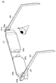
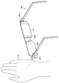
- FIGS. 3 and 4 are explanatory diagrams for explaining the outline of the input interface according to the present embodiment.
- the information processing apparatus 10 is, for example, an imaging unit that captures an image of an external environment (for example, real object recognition, self-position estimation, etc.) such as a stereo camera provided in a head-mounted device.
- the imaging unit used in the above is used for recognizing user input. Therefore, in this description, an outline of the input interface according to the present embodiment will be described by taking as an example the case where the imaging units 201a and 201b are used for user input recognition in the input / output device 20 described with reference to FIG. To do.
- the user can give various instructions to the information processing apparatus 10 by covering at least a part of the imaging units 201a and 201b with a part such as a hand. .
- the information processing apparatus 10 recognizes a user input according to whether or not at least some of the imaging units 201a and 201b are in a predetermined shielding state.
- the predetermined shielding state includes, for example, a state where substantially the entire angle of view of a desired imaging unit is shielded.
- the predetermined shielding state is described as indicating a state in which substantially the entire angle of view of the desired imaging unit is shielded, but the present invention is not necessarily limited to this state.
- FIG. 3 shows a situation where the angle of view of the imaging unit 201a is shielded by the user's hand U11.
- the information processing apparatus 10 determines whether substantially the entire angle of view of the imaging unit 201a is shielded based on a predetermined method. It is recognized that a predetermined input has been made (that is, a user input is recognized).
- the imaging unit 201a corresponds to an example of a “first imaging unit”. That is, the above-described determination regarding the shielding state of the imaging unit 201a (for example, determination of whether substantially the entire angle of view of the imaging unit 201a is blocked) corresponds to an example of “first determination”.
- FIG. 4 shows a situation where the angle of view of the imaging unit 201b is blocked by the user's hand U13.
- the information processing apparatus 10 determines whether substantially the entire angle of view of the imaging unit 201 b is shielded, and according to the determination result. Recognize user input.
- the imaging unit 201b corresponds to an example of a “second imaging unit”. That is, the above determination regarding the shielding state of the imaging unit 201b corresponds to an example of “second determination”.
- the method is not particularly limited as long as it is possible to determine whether substantially the entire angle of view of each of the imaging units 201a and 201b is blocked.
- the information processing apparatus 10 determines whether substantially the entire angle of view of each of the imaging units 201a and 201b is shielded based on the brightness of the images captured by the imaging units 201a and 201b. You may judge.
- a method for determining whether substantially the entire angle of view of the image capturing unit is shielded according to the brightness of the image captured by the predetermined image capturing unit will be described later in detail as an example.
- various sensors such as a proximity sensor and a distance measuring sensor.
- the distance detection result is When the value is equal to or less than the threshold value, it may be determined that substantially the entire angle of view is shielded.
- the information processing apparatus 10 can recognize a user input depending on, for example, whether substantially the entire angle of view of any of the imaging units 201a and 201b is shielded. It becomes.
- the information processing apparatus 10 may recognize a user input according to a combination of imaging units in which the entire angle of view is shielded among the imaging units 201a and 201b.
- the information processing apparatus 10 has a case where substantially the entire angle of view is shielded only for one of the imaging units 201a and 201b when both of the imaging units 201a and 201b are shielded. It is also possible to recognize that an input different from that is made.
- FIG. 5 is a block diagram illustrating an example of a functional configuration of the information processing system 1 according to the present embodiment. Therefore, hereinafter, as described with reference to FIG. 1, assuming that the information processing system 1 includes the information processing apparatus 10 and the input / output apparatus 20, the configurations of the information processing apparatus 10 and the input / output apparatus 20 are described. This will be described in more detail. As illustrated in FIG. 5, the information processing system 1 may include a storage unit 190.
- the input / output device 20 includes imaging units 201 a and 201 b and an output unit 210.
- the output unit 210 includes a display unit 211.
- the output unit 210 may include a sound output unit 213.
- the imaging units 201a and 201b correspond to the imaging units 201a and 201b described with reference to FIG. Note that the imaging units 201a and 201b may be simply referred to as “imaging unit 201” if they are not particularly distinguished.
- the display unit 211 corresponds to the display unit 211 described with reference to FIG.
- the acoustic output unit 213 includes an acoustic device such as a speaker and outputs sound and sound corresponding to information to be output.
- the information processing apparatus 10 includes a determination unit 101, a recognition unit 103, a process execution unit 105, and an output control unit 107.
- the determination unit 101 acquires information according to the imaging result of the image from the imaging unit 201, and substantially the entire angle of view of the imaging unit is blocked by some real object (for example, a user's hand) according to the acquired information. It is determined whether or not it has been done.
- the determination unit 101 acquires an image captured by the image capturing unit 201 from the image capturing unit 201, and displays the image of the image capturing unit 201 according to the brightness of the acquired image (for example, luminance distribution for each pixel). It may be determined whether substantially the entire corner is shielded. As a more specific example, the determination unit 101 calculates the average value of the luminance of each pixel of the acquired image, and when the calculated average value of luminance is equal to or less than the threshold, the image of the imaging unit 201 that has captured the image. It may be determined that substantially the entire corner is shielded.
- the determination unit 101 calculates the average value of the luminance of each pixel of the acquired image, and when the calculated average value of luminance is equal to or less than the threshold, the image of the imaging unit 201 that has captured the image. It may be determined that substantially the entire corner is shielded.
- the determination unit 101 acquires an image captured from the image capturing unit 201 and determines that recognition of an object in real space (that is, a real object) is difficult based on the acquired image, It may be determined that substantially the entire angle of view of the imaging unit 201 is shielded.
- the determination unit 101 has difficulty extracting feature points for recognizing a real object from an acquired image (for example, when the number of extracted feature points is equal to or less than a threshold), the image It may be determined that substantially the entire angle of view of the imaging unit 201 that captured the image is shielded.
- the above-described example is merely an example, and the method is not particularly limited as long as the determination unit 101 can determine whether substantially the entire angle of view of the imaging unit 201 is blocked.
- the determination unit 101 detects the proximity of a real object to the imaging unit 201 by a distance measuring sensor, a proximity sensor, or the like, the entire angle of view of the imaging unit 201 is shielded. You may judge.
- the number of imaging units 201 to be determined by the determination unit 101 is not particularly limited. As a specific example, the determination unit 101 may determine only one of the imaging units 201a and 201b, or may determine both the imaging units 201a and 201b. In addition, the determination unit 101 may set other image capturing units other than the image capturing units 201a and 201b as a determination target. That is, the determination unit 101 may determine three or more imaging units as a determination target.
- the timing at which the determination unit 101 performs the above-described determination is not particularly limited.
- the determination unit 101 may periodically perform the determination at every predetermined timing.
- the determination unit 101 may perform the above determination according to a predetermined trigger.
- the determination unit 101 may perform the above determination when predetermined display information such as an operation menu for prompting user input is displayed on the display unit 211. In this case, for example, the determination unit 101 may recognize whether or not predetermined display information is displayed on the display unit 211 based on a notification from the output control unit 107 described later.
- the determination unit 101 notifies the recognition unit 103 of information indicating a determination result as to whether or not substantially the entire angle of view of the imaging unit 201 is blocked. At this time, for example, when the determination unit 101 determines that substantially the entire angle of view of the predetermined imaging unit 201 is blocked, the determination unit 101 may notify the recognition unit 103. In addition, when there are a plurality of candidates for the imaging unit 201 to be determined, the determination unit 101 may notify the recognition unit 103 of information indicating a determination result for each imaging unit 201.
- the recognition unit 103 acquires information indicating a determination result as to whether or not substantially the entire angle of view of the imaging unit 201 is blocked from the determination unit 101, and recognizes user input based on the acquired information. At this time, the recognizing unit 103 may recognize the user input in accordance with information related to user input recognition displayed on the display unit 211 and information indicating the determination result.
- FIG. 6 is an explanatory diagram for explaining an example of the input interface according to the present embodiment, and shows an example of an operation menu presented via the display unit 211 of the input / output device 20.
- reference numeral V101 schematically shows an optical image of real space visually recognized by the user.
- Reference numeral V ⁇ b> 103 indicates an area (that is, a drawing area) where display information (for example, a virtual object) is presented via the display unit 211.
- Reference numerals V105 and V107 indicate examples of display information presented as operation menus. Specifically, the display information V105 is associated with an operation menu that indicates permission of execution of a predetermined process, and the display information V107 is associated with an operation menu that indicates cancellation of execution of the process. Yes.
- the recognition unit 103 for example, of the imaging unit 201b positioned on the left side relative to the user wearing the input / output device 20 (that is, the imaging unit 201b shown in FIG. 2).
- the recognition unit 103 recognizes that the user has given an instruction to affirm the execution of the predetermined process. That is, the recognizing unit 103 recognizes the above operation by the user as a user input meaning affirmation.
- the recognition unit 103 is configured to block substantially the entire angle of view of the imaging unit 201a (that is, the imaging unit 201a illustrated in FIG. 2) positioned on the right side relative to the user wearing the input / output device 20. Recognizes that the operation menu corresponding to the display information V107 has been selected. In this case, the recognizing unit 103 recognizes that an instruction to cancel execution of a predetermined process has been given by the user. That is, the recognizing unit 103 recognizes the above-described operation by the user as a user input meaning cancellation.
- the recognition unit 103 may execute the above-described processing related to recognition of user input in response to a predetermined trigger.
- the recognition unit 103 may execute processing related to user input recognition when predetermined display information such as an operation menu for prompting user input is displayed on the display unit 211. .
- the recognition unit 103 may recognize whether or not predetermined display information is displayed on the display unit 211 based on a notification from the output control unit 107, for example.
- the recognition unit 103 outputs information indicating the recognition result of the user input to the process execution unit 105.
- the process execution unit 105 is configured to execute various functions (for example, applications) provided by the information processing apparatus 10 (and thus the information processing system 1). For example, the process execution unit 105 extracts a corresponding application from a predetermined storage unit (for example, a storage unit 190 described later) in accordance with the recognition result of the user input by the recognition unit 103, and executes the extracted application. Good. Further, the process execution unit 105 may control the operation of the application being executed according to the recognition result of the user input by the recognition unit 103. For example, the process execution unit 105 may switch the subsequent operation of the application being executed according to the operation menu selected by the user. Further, the process execution unit 105 may output information indicating execution results of various applications to the output control unit 107.
- a predetermined storage unit for example, a storage unit 190 described later
- the output control unit 107 presents the information to the user by causing the output unit 210 to output various types of information to be output.
- the output control unit 107 may present the display information to the user by causing the display unit 211 to display display information to be output.
- the output control part 107 may show the said information to a user by making the sound output part 213 output the sound according to the information used as output object.
- the output control unit 107 may acquire information indicating the execution results of various applications from the process execution unit 105, and present output information corresponding to the acquired information to the user via the output unit 210.
- the output control unit 107 displays display information corresponding to the operation menu of the application, such as the display information V105 and V107 shown in FIG. It may be displayed.
- the output control unit 107 may cause the display unit 211 to display display information indicating the execution result of a desired application.
- the output control unit 107 may cause the acoustic output unit 213 to output output information corresponding to the execution result of a desired application as voice or sound.
- the output control unit 107 may notify the determination unit 101 and the recognition unit 103 of information indicating the output status of various types of output information via the output unit 210.
- the output control unit 107 indicates that the information is displayed.
- the determination unit 101 and the recognition unit 103 may be notified.
- the storage unit 190 is a storage area for storing various data temporarily or permanently.
- the storage unit 190 may store data for the information processing apparatus 10 to execute various functions.
- the storage unit 190 may store data (for example, a library) for executing various applications, management data for managing various settings, and the like.
- the functional configuration of the information processing system 1 shown in FIG. 5 is merely an example, and the functional configuration of the information processing system 1 is not necessarily the example shown in FIG. 5 if the processing of each configuration described above can be realized. It is not limited to only.
- the input / output device 20 and the information processing device 10 may be integrally configured.
- the storage unit 190 may be included in the information processing apparatus 10 or a recording medium external to the information processing apparatus 10 (for example, externally attached to the information processing apparatus 10). Recording medium).
- a part of the configuration of the information processing apparatus 10 may be provided outside the information processing apparatus 10 (for example, a server).
- FIG. 7 is a flowchart showing an example of a flow of a series of processes of the information processing system 1 according to the present embodiment.
- the information processing apparatus 10 acquires information according to the imaging result of an image from a predetermined imaging unit 201 held in the input / output device 20, and displays an image of the imaging unit according to the acquired information. It is determined whether or not substantially the entire corner is blocked by some real object (for example, a user's hand) (S101).
- the information processing apparatus 10 determines that the angle of view is blocked.
- the user input is recognized according to the imaging unit (S105).
- the information processing apparatus 10 executes processing according to the recognition result of the user input (S107).
- the information processing apparatus 10 may execute a corresponding application according to the recognition result of the user input.
- the information processing apparatus 10 may present output information corresponding to the execution result of the application to the user via the output unit 210.
- the information processing apparatus 10 does not execute the processing according to the reference numerals S103 and 107, You may change to the subsequent processing.
- the trigger for the information processing apparatus 10 to execute a series of processes indicated by reference numerals S101 to S107 is not particularly limited.
- the information processing apparatus 10 may execute the series of processes in response to a predetermined trigger.
- the information processing apparatus 10 may execute the above-described series of processes when the user is prompted to input information via the input / output device 20.
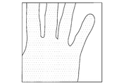
- FIG. 8 shows an example of an image picked up by the image pickup unit when the angle of view of the predetermined image pickup unit is blocked by a hand, and shows a case where the distance between the image pickup unit and the hand is about 20 cm. ing.
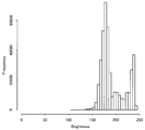
- FIG. 9 is a graph showing the luminance distribution of each pixel of the image shown in FIG.
- the horizontal axis indicates the luminance of the pixel
- the vertical axis indicates the frequency.
- the luminance of each pixel indicates a value from 0 to 255, and the higher the value, the higher the luminance.
- FIG. 9 in the example shown in FIG. 8, it can be seen that many pixels having relatively high luminance are distributed.
- leakage of light from the external environment from an area not shielded by the hand contributes. It is presumed that
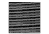
- FIG. 10 shows an example of an image picked up by the image pickup unit when the angle of view of the predetermined image pickup unit is shielded by hand, and shows a case where the distance between the image pickup unit and the hand is about 10 cm. ing.
- the area shielded by the hand in the angle of view of the imaging unit is wider, and the brightness of the entire image is also darker.
- FIG. 11 is a graph showing the luminance distribution of each pixel of the image shown in FIG. Note that the horizontal and vertical axes in FIG. 11 are the same as those in the graph shown in FIG.
- the image shown in FIG. 10 has more pixels with lower luminance than the image shown in FIG. That is, it can be seen that the brightness of the entire image shown in FIG. 10 is darker than the brightness of the entire image shown in FIG.
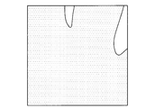
- FIG. 12 shows an example of an image captured by the imaging unit when the angle of view of the predetermined imaging unit is shielded by a hand, and shows a case where the distance between the imaging unit and the hand is about 1 cm. ing.
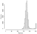
- FIG. 13 is a graph showing the luminance distribution of each pixel of the image shown in FIG. Note that the horizontal and vertical axes in FIG. 13 are the same as those in the graph shown in FIG.
- the image shown in FIG. 12 has more pixels with lower luminance than the image shown in FIG.
- each pixel has a brightness that is brighter than black, although it is slight, because light from the external environment leaks from the gap between the imaging unit and the hand. I guess that.
- FIG. 14 shows an example of an image captured by the imaging unit when the angle of view of the predetermined imaging unit is shielded by a hand, and shows a case where the distance between the imaging unit and the hand is about 1 mm. ing.
- FIG. 15 is a graph showing the luminance distribution of each pixel of the image shown in FIG. Note that the horizontal and vertical axes in FIG. 15 are the same as those in the graph shown in FIG. As can be seen by comparing FIG. 15 and FIG. 13, the image shown in FIG.
- the imaging unit used in the present embodiment when the luminance distribution of each pixel of the captured image is as shown in FIG. It can be regarded as a boundary (threshold value) for determining whether or not substantially the entire corner is shielded. That is, in the imaging unit used in the present embodiment, for example, when the average value of the luminance of each pixel of the captured image shows a value of 77 or less, substantially the entire angle of view of the imaging unit is shielded. Can be considered as being.
- the threshold for determining whether substantially the entire angle of view of the imaging unit is blocked is the configuration, installation position, installation method, and the like of the imaging unit. Needless to say, it may be appropriately changed according to the various conditions.
- Modification 1 Notification of information regarding the shielding state of the angle of view of the imaging unit
- the head-mounted device such as the input / output device 20 is used by being mounted on the head, so that the user is positioned in front of each of the components of the input / output device 20 according to the wearing state. It becomes difficult to visually recognize other parts other than the part directly. Therefore, for example, when the imaging units 201a and 201b illustrated in FIG. 2 are used for determination of user input, the user can directly visually recognize the imaging units 201a and 201b in a state where the input / output device 20 is mounted. It can be difficult.
- the information processing apparatus 10 outputs the notification information according to the shielding state of the angle of view of the imaging unit used for the determination of the user input, so that the shielding state is determined by the user. May be notified.
- FIG. 17 is an explanatory diagram for describing an example of a user interface according to the first modification.
- an example of a user interface will be described assuming that the imaging units 201a and 201b are used for determination of user input, assuming that the input / output device 20 illustrated in FIG. 2 is used.
- the objects to which reference numerals V201 to V207 are attached correspond to the objects to which reference numerals V101 to v107 are attached in the example described with reference to FIG. Omitted.
- images taken by the imaging units 201a and 201b used for determination of user input are displayed in the drawing area V203.
- images captured by the imaging units 201 a and 201 b are presented to the user via the display unit 211.
- a reference symbol V213 indicates an image captured by the imaging unit 201b that is positioned on the left side relative to the user wearing the input / output device 20, and the region indicated by the reference symbol V209 Is displayed.
- the imaging unit 201b is associated with an operation menu corresponding to the display information V205. Based on such a situation, for example, when the user selects an operation menu corresponding to the display information V205, the angle of view of the imaging unit 201b is blocked by checking the image V213 displayed in the region V209. It is possible to visually confirm the situation (that is, whether or not substantially the entire angle of view is blocked). For example, in the example illustrated in FIG. 17, the angle of view of the imaging unit 201b is blocked by the user's hand indicated by reference symbol U13, and the user's hand U13 is captured as an object in the image V213.
- reference numeral V215 indicates an image captured by the imaging unit 201a located on the right side relative to the user wearing the input / output device 20, and is displayed in the area indicated by reference numeral V211.
- the imaging unit 201a is associated with an operation menu corresponding to the display information V207. Based on such a situation, for example, when the user selects an operation menu corresponding to the display information V207, the angle of view of the imaging unit 201a is blocked by checking the image V215 displayed in the region V211. It is possible to visually confirm the situation (that is, whether or not substantially the entire angle of view is blocked).
- the imaging unit is confirmed while confirming the image presented via the display unit 211. It is possible to shield the angle of view with a hand or the like.
- the example described with reference to FIG. 17 is merely an example, and if the user can be notified of the situation where the angle of view of the imaging unit used for determination of user input is blocked, the user is notified.
- the type of information that is, notification information
- the notification method of the information and the like.
- the information processing apparatus 10 uses the notification information according to the situation where the angle of view of the imaging unit used for determination of the user input is shielded (for example, the ratio of being shielded) as sound, such as a speaker. You may show to a user via a sound output part. As a specific example, when the angle of view of the imaging unit located on the left side relative to the user is shielded, the information processing apparatus 10 starts from a speaker located on the left side relative to the user. Sounds such as sound effects may be output at a volume corresponding to the ratio at which the angle of view is shielded.
- the information processing apparatus 10 is output from a speaker, for example, as the user's hand approaches a predetermined imaging unit (that is, the brightness of an image captured by the imaging unit becomes darker). You may control so that the volume of the sound to be increased may become larger.
- Modification 1 an example of a user interface in the case of notifying the user of the situation where the angle of view of the imaging unit is blocked will be described with reference to FIG.
- Modification 2 Presentation of information on the method of shielding the angle of view of the imaging unit
- the user directly places other portions of the input / output device 20 other than the portion positioned in front of the eyes according to the wearing state. It becomes difficult to visually recognize. Therefore, it may be difficult for the user to directly view the imaging units (for example, the imaging units 201a and 201b illustrated in FIG. 2) used for determining the user input in a state where the input / output device 20 is mounted. .
- the imaging units for example, the imaging units 201a and 201b illustrated in FIG. 2 used for determining the user input in a state where the input / output device 20 is mounted.
- the information processing apparatus 10 provides notification information for notifying a method of shielding the angle of view of the miscellaneous portion used for determination of user input (that is, an operation method). You may notify a user.
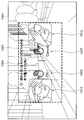
- FIG. 18 is an explanatory diagram for describing an example of a user interface according to the second modification.
- an example of a user interface will be described assuming that the imaging units 201a and 201b are used for determination of user input, assuming that the input / output device 20 illustrated in FIG. 2 is used.
- the objects to which reference numerals V301 to V307 are attached correspond to the objects to which reference numerals V101 to v107 are attached in the example described with reference to FIG. Omitted.
- the information processing apparatus 10 uses the operation method (that is, the method of shielding the angle of view of the imaging unit) when a state in which no user input is detected continues for a predetermined period after prompting the user to perform an operation. ) To present notification information.
- the operation method that is, the method of shielding the angle of view of the imaging unit
- the information processing apparatus 10 prompts the user to perform an operation by presenting the notification information V309 in the drawing area V303.
- the information processing apparatus 10 notifies the user of the operation method by presenting the notification information V311 and V313 when a state in which no user input is detected continues for a predetermined period or longer. Yes.
- the notification information V311 is an image of a method of shielding the angle of view of the imaging unit 201b located on the left side relative to the user as an operation method for selecting an operation menu corresponding to the display information V305. As shown. That is, the information processing apparatus 10 notifies the user of an operation method for selecting an operation menu corresponding to the display information V305 by presenting the notification information V311 in the vicinity of the display information V305.
- the notification information V313 shows, as an image, a method of shielding the angle of view of the imaging unit 201a positioned on the right side relative to the user as an operation method for selecting an operation menu corresponding to the display information V307. Yes. That is, the information processing apparatus 10 notifies the user of an operation method for selecting an operation menu corresponding to the display information V307 by presenting the notification information V313 in the vicinity of the display information V307.
- the example illustrated in FIG. 18 is merely an example, and if the operation method (that is, the method of shielding the angle of view of the imaging unit) can be notified to the user, the type of notification information and the notification method are not necessarily limited. It is not limited to the example shown in FIG.
- the information processing apparatus 10 recognizes a user input according to whether or not substantially the entire angle of view of a predetermined imaging unit is blocked.
- the information processing apparatus 10 according to the modification 3 has the first shielding state and the shielding amount of the angle of view as compared to the first shielding state as the shielding state of the angle of view of the predetermined imaging unit.
- a small second shielding state is identified and each is recognized as a different user input.
- examples of the first shielding state include a state where substantially the entire angle of view of a predetermined imaging unit is shielded.
- a 2nd shielding state the state by which only a part of angle of view of the said imaging part is shielded is mentioned.
- the information processing apparatus 10 identifies a state where substantially the entire angle of view of the predetermined imaging unit is shielded and a state where only a part of the angle of view is shielded. explain.
- a state where substantially the entire angle of view of a predetermined imaging unit is blocked is associated with a state where a predetermined button is pressed, only a part of the angle of view is blocked. May be associated with a state in which the button is half-pressed.
- the criteria for determining each of the state where the angle of view is not occluded, the state where only a part of the angle of view is occluded, and the state where almost the entire angle of view is occluded are not particularly limited. What is necessary is just to set suitably according to a utilization form. As a specific example, when the user input is determined based on the brightness of the image captured by the imaging unit, only a part of the angle of view is blocked, and substantially the entire angle of view is blocked. What is necessary is just to set suitably the threshold value for discriminating each of the present state.
- Modification 3 an example of a method for recognizing user input in accordance with the shielding state of the angle of view of the imaging unit is described.
- Modification 4 An example of control according to the external environment
- the brightness of the image May vary depending on the brightness of the external environment.
- “brightness of the external environment” may be regarded as the intensity of ambient light around the information processing apparatus 10 in a state where the angle of view of the imaging unit is not shielded. Therefore, for example, depending on whether the external environment is bright or dark, the manner in which the brightness of an image to be captured varies depending on whether the angle of view of the imaging unit is blocked or not. For example, in a situation where the external environment is relatively bright, the amount of change in the brightness of the captured image is relatively large depending on whether substantially the entire angle of view of the imaging unit is blocked.
- an image of an image to be captured is determined depending on whether or not substantially the entire angle of view of the imaging unit is shielded. The amount of change in brightness decreases.
- the information processing apparatus 10 separately detects the brightness of the external environment using, for example, an illuminance sensor and the like.
- a threshold value for determining whether or not the whole is shielded may be dynamically controlled.
- the information processing apparatus 10 determines whether or not the angle of view of the imaging unit is blocked when the brightness detection result of the external environment is equal to or less than the threshold (that is, user input). Recognition) may be temporarily suppressed.
- the method is not necessarily limited to a method using an illuminance sensor as long as recognition of user input can be temporarily suppressed depending on whether the external environment is bright or not.
- the external environment is bright
- the brightness of the image captured by the other imaging unit It becomes brighter.
- the image was picked up by another image pickup unit even when substantially the entire angle of view of only some of the image pickup units is blocked. The image becomes darker. From such characteristics, for example, when the information processing apparatus 10 determines that substantially the entire angle of view of only a part of the plurality of imaging units is blocked (in other words, approximately the entire angle of view).
- the user input may be recognized according to the shielding state only when the number of imaging units determined to be shielded is equal to or less than the threshold.
- the information processing apparatus 10 is configured such that when the number of imaging units that are determined to be substantially shielded for the entire angle of view exceeds the threshold value (as a result, substantially the entire angle of view is shielded for all of the plurality of imaging units).
- the user input may be restricted.
- Modification 5 Example of user input recognition method using a plurality of imaging units
- the angle of view of each of the two image pickup units can be blocked by using both hands.
- the information processing apparatus 10 may recognize a user input according to a combination of imaging units in which substantially the entire angle of view is shielded among the plurality of imaging units.
- a combination of imaging units in which substantially the entire angle of view is shielded among the plurality of imaging units.
- four imaging units are used for user input recognition and the angle of view of each imaging unit is shielded by hand, at most two of the four imaging units are used. The angle of view of the imaging unit is shielded.
- each of six states ( 4 C 2 ) corresponding to a combination of two imaging units whose field angles are shielded among the four imaging units, and any one of the four imaging units.
- Each of the four states ( 4 C 1 ) corresponding to the case where the angle of view of only one imaging unit is blocked can be individually recognized as different user inputs.
- the information processing apparatus 10 may recognize a user input according to a combination of imaging units in which substantially the entire angle of view is shielded among a plurality of imaging units.
- a function that requires an explicit instruction from the user such as a shutdown
- a combination of imaging units that cannot easily block the angle of view unless both hands are used May be assigned.
- the function assigned to the above operation is not limited to shutdown.
- a function (so-called undo) for canceling a previously executed process may be assigned to the above operation.
- the information processing apparatus 10 determines in time division whether substantially the entire angle of view of any of the plurality of imaging units is shielded in a predetermined time width.
- the user input may be recognized according to the imaging unit that is entirely shielded and the timing at which the shielding is determined.
- the information processing apparatus 10 recognizes different user inputs according to the order in which the angles of view are shielded in time division. May be. That is, the information processing apparatus 10 performs a process in which each of the field angles is shielded in the order of the imaging unit 201a and the imaging unit 201b, and in a case where each field angle is shielded in the order of the imaging unit 201b and the imaging unit 201a. It may be recognized as a different user input.
- an image of the imaging unit 201a positioned on the right side relative to the user after substantially the entire angle of view of the imaging unit 201b positioned on the left side relative to the user is shielded. It is assumed that substantially the entire corner is shielded. In this case, for example, the information processing apparatus 10 has been operated with directionality from the left side to the right side according to the timing at which substantially the entire angle of view of each of the imaging units 201b and 201a is blocked. You may recognize.
- the entire angle of view of the imaging unit 201b positioned relatively on the left side of the user is It shall be shielded.
- the information processing apparatus 10 has been operated with directionality from the right side to the left side according to the timing at which substantially the entire angle of view of each of the imaging units 201a and 201b is blocked. You may recognize.
- the information processing apparatus 10 can also recognize an operation having directionality such as a so-called swipe operation.
- the information processing apparatus 10 may recognize different user inputs depending on the direction in which an imaging unit in which substantially the entire angle of view is shielded among a plurality of imaging units is installed. For example, when the input interface according to the present embodiment is applied to a device such as a smartphone, when the entire angle of view of the imaging unit on the front side is shielded, the device is placed upside down. It may be recognized and locked.
- Modification 6 An example of a method for recognizing user input in accordance with an imaging state
- a sixth modification as an example of a user input recognition method using an imaging unit, a case where the imaging state of an image by the imaging unit is used for user input recognition will be described.
- various states relating to image capture may differ from the case where the angle of view is not shielded.
- focus control for example, AF: Autofocus
- the information processing apparatus 10 may determine that substantially the entire angle of view of the imaging unit is shielded.
- the information processing apparatus 10 determines whether or not substantially the entire angle of view of the imaging unit is shielded based on the exposure control (AE: Automatic Exposure) state or the like (that is, recognition of user input). You may use it.
- AE Automatic Exposure
- the information processing apparatus 10 determines whether substantially the entire angle of view of a predetermined imaging unit used for user input recognition is blocked. Recognize user input.
- the situation where the angle of view of the imaging unit is shielded is not necessarily the case where the user is intentionally shielded using a hand or the like.
- a certain object for example, another person other than the user
- crosses in front of the imaging unit to temporarily block the angle of view of the imaging unit.
- a certain object for example, another person other than the user
- the information processing apparatus 10 determines that substantially the entire field angle of the predetermined imaging unit is shielded, the state in which the field angle is shielded is the intention of the user. It may be possible to prevent erroneous recognition of user input by verifying whether or not it is caused by an operation.
- the information processing apparatus 10 determines whether substantially the entire angle of view of the imaging unit is blocked based on an image captured by a predetermined imaging unit, the information processing apparatus 10 Depending on the mode of change, it may be verified whether or not the angle of view is blocked by a user's intentional operation.
- the image change for example, brightness
- the change in the image may be regarded as a change in the shielding amount of the angle of view.
- the information processing apparatus 10 determines that at least a part of the angle of view of the predetermined imaging unit is shielded, images captured by the imaging unit before and after the determination It may be verified whether or not the angle of view is blocked by the user's intentional operation according to the change rate (the change rate of the shielding amount). That is, whether or not the operation input is recognized is controlled according to the change speed of the shielding amount of the angle of view of the imaging unit.
- the change speed is equal to or higher than a predetermined value
- recognition of a user's operation input may be restricted when change rate is below a predetermined value.
- the information processing apparatus 10 may set a determination time for determining whether substantially the entire angle of view of the predetermined imaging unit is shielded. That is, the information processing apparatus 10 may control whether to recognize a user input according to the duration of the predetermined shielding state. More specifically, the information processing apparatus 10 is configured such that a state in which substantially the entire angle of view of a predetermined imaging unit is shielded continues for the determination time or longer (that is, the duration is equal to or longer than the determination time). In other words, it may be recognized that the angle of view is blocked by the user's intentional operation.
- the information processing apparatus 10 may control the determination time according to a combination of imaging units in which substantially the entire angle of view is blocked. .
- the information processing apparatus 10 may control the determination time to be relatively short.
- a situation in which the angle of view of only one of the plurality of imaging units is shielded does not always occur due to a user's intentional operation, but occurs accidentally due to an event. There is also a possibility to do. Therefore, in this case, the information processing apparatus 10 may perform control so that the determination time is longer than when the angle of view of the plurality of imaging units is shielded.
- the information processing apparatus 10 is provided between an imaging unit and an object (for example, a hand) that blocks an angle of view of the imaging unit using various sensors such as a distance measurement sensor and a proximity sensor. Using the distance detection result, it may be verified whether or not the angle of view is blocked by the user's intentional operation.
- the distance between the imaging unit and the shielding object is several centimeters.
- the distance between the imaging unit and the shielding object is at least a few tens of centimeters apart It is estimated to be.
- the information processing apparatus 10 determines that the angle of view of the predetermined imaging unit is shielded, the detection result of the distance between the imaging unit and the shielding object is equal to or less than the threshold value. In this case, it may be recognized that the angle of view is blocked by a user's intentional operation.
- the information processing apparatus 10 temporarily suppresses recognition of user input according to the brightness of the external environment by an illuminance sensor or the like, so that the external environment is dark. The occurrence of a situation that erroneously recognizes that the angle of view of the imaging unit is shielded may be prevented.
- Modification 8 Example of control combined with other input interface
- modification 8 an example of control when the input interface according to the present embodiment is combined with another input interface will be described.
- the modification 8 by using the recognition result of the user input based on the input interface according to the present embodiment as a function similar to the shift key in the keyboard input, the user input via the other input interface is performed. A case where the recognition result is controlled will be described.
- the number of recognizable user inputs is determined according to the number of keys from the characteristic of recognizing user inputs according to pressed keys.
- the keyboard input it is possible to selectively switch the user input recognized according to the pressed key depending on whether or not the shift key is pressed. With such a mechanism, it is possible to recognize user inputs having a pattern larger than the number of keys in keyboard input.
- the information processing apparatus 10 recognizes a user input that is subsequently input when it is determined that substantially the entire angle of view of the predetermined imaging unit is blocked, for example. It may be recognized that the result switching is instructed.
- the information processing apparatus 10 recognizes the gesture as an operation for selecting a target virtual object when a gesture of simply hitting the virtual object is performed.
- the information processing apparatus 10 uses the gesture as a target virtual object. You may recognize as operation for erasing.
- the correspondence relationship between a predetermined gesture and a user input recognized by the gesture may be selectively switched according to a combination of imaging units in which substantially the entire angle of view is blocked.
- the image capturing units 201a and 201b illustrated in FIG. 2 are used for user input, the image capturing unit 201a and 201b continues depending on which of the angle of view is almost entirely shielded. Different user inputs may be recognized based on the gesture input.
- substantially the entire angle of view of both the imaging units 201a and 201b is shielded
- substantially the entire angle of view of only one of the imaging units 201a and 201b is shielded based on the continuously input gesture.
- a user input different from the case where it is performed may be recognized.
- the input interface according to the present embodiment can also be used as a trigger for detecting a predetermined operation via another input interface.
- the input interface according to the present embodiment can also be used as a trigger for detecting a predetermined operation via another input interface.
- the number of recognizable patterns can be limited. Therefore, by combining the input interface according to the present embodiment with gesture input, for example, it is possible to expect effects such as improvement of gesture recognition accuracy and reduction of processing load related to gesture recognition.
- the information processing apparatus 10 when the information processing apparatus 10 controls the recognition result of the user input via another input interface based on the input interface according to the present embodiment, the information processing apparatus 10 notifies the user of the control status. May be.
- the information processing apparatus 10 switches the correspondence between a gesture input thereafter and a user input because substantially the entire angle of view of a predetermined imaging unit is shielded.
- the display information indicating that the switching is being performed may be fed back to the user via the display unit 211.
- the user can recognize that the correspondence relationship between the gesture input thereafter and the user input recognized by the gesture is switched.
- Modification 9 Example of user input recognition method using sound collection unit
- a function equivalent to the input interface according to the present embodiment is realized by using a device different from the imaging unit.
- a sound collection unit such as a microphone
- the information processing apparatus 10 receives the user input according to the sound collection result of the sound (in other words, acoustic noise) generated when the sound collection unit is struck by the sound collection unit used for user input recognition. May be recognized.
- the operation of shielding substantially the entire angle of view of the predetermined imaging unit is replaced with the operation of hitting the predetermined sound collecting unit.
- the user input can be recognized in the same manner as the information processing system 1 according to the embodiment.
- notification information for example, a graph indicating the sound collection result of the sound
- the user may be notified via the display unit 211.
- notification information indicating the position of the sound collection unit may be notified to the user via the display unit 211.
- the angle of view is spread over the entire periphery of the camera. From such a situation, for example, when the omnidirectional camera is used for determination of user input, the information processing apparatus 10 divides the angle of view of the omnidirectional camera into a plurality of partial areas, and A part of the partial area may be used for determination of user input. That is, the information processing apparatus 10 determines whether or not substantially all of a predetermined partial area is shielded from the angle of view of the omnidirectional camera, or a combination of partial areas where substantially the entire partial area is shielded. The user input may be recognized according to the above. In this case, the information processing apparatus 10 may notify the user of notification information for notifying the user of an area used for determination of user input via the display unit 211.
- FIG. 19 is a functional block diagram illustrating a configuration example of the hardware configuration of the information processing apparatus configuring the information processing system according to an embodiment of the present disclosure.
- the information processing apparatus 900 constituting the information processing system according to the present embodiment mainly includes a CPU 901, a ROM 902, and a RAM 903.
- the information processing apparatus 900 further includes a host bus 907, a bridge 909, an external bus 911, an interface 913, an input device 915, an output device 917, a storage device 919, a drive 921, and a connection port 923. And a communication device 925.
- the CPU 901 functions as an arithmetic processing unit and a control unit, and controls all or a part of the operation in the information processing apparatus 900 according to various programs recorded in the ROM 902, the RAM 903, the storage apparatus 919, or the removable recording medium 927.
- the ROM 902 stores programs used by the CPU 901, calculation parameters, and the like.
- the RAM 903 primarily stores programs used by the CPU 901, parameters that change as appropriate during execution of the programs, and the like. These are connected to each other by a host bus 907 constituted by an internal bus such as a CPU bus.
- a host bus 907 constituted by an internal bus such as a CPU bus.
- the host bus 907 is connected to an external bus 911 such as a PCI (Peripheral Component Interconnect / Interface) bus via a bridge 909.
- an input device 915, an output device 917, a storage device 919, a drive 921, a connection port 923, and a communication device 925 are connected to the external bus 911 via an interface 913.
- the input device 915 is an operation means operated by the user, such as a mouse, a keyboard, a touch panel, a button, a switch, a lever, and a pedal. Further, the input device 915 may be, for example, remote control means (so-called remote control) using infrared rays or other radio waves, or an external connection device such as a mobile phone or a PDA corresponding to the operation of the information processing device 900. 929 may be used. Furthermore, the input device 915 includes an input control circuit that generates an input signal based on information input by a user using the above-described operation means and outputs the input signal to the CPU 901, for example. A user of the information processing apparatus 900 can input various data and instruct a processing operation to the information processing apparatus 900 by operating the input device 915. For example, the input unit 221 illustrated in FIG. 7 can be configured by the input device 915.
- the output device 917 is a device that can notify the user of the acquired information visually or audibly. Examples of such devices include CRT display devices, liquid crystal display devices, plasma display devices, EL display devices, display devices such as lamps, audio output devices such as speakers and headphones, printer devices, and the like.
- the output device 917 outputs results obtained by various processes performed by the information processing apparatus 900. Specifically, the display device displays results obtained by various processes performed by the information processing device 900 as text or images.
- the audio output device converts an audio signal composed of reproduced audio data, acoustic data, and the like into an analog signal and outputs the analog signal. For example, the output unit 210 illustrated in FIG.
- the storage device 919 is a data storage device configured as an example of a storage unit of the information processing device 900.
- the storage device 919 includes, for example, a magnetic storage device such as an HDD (Hard Disk Drive), a semiconductor storage device, an optical storage device, or a magneto-optical storage device.
- the storage device 919 stores programs executed by the CPU 901 and various data.
- the drive 921 is a reader / writer for a recording medium, and is built in or externally attached to the information processing apparatus 900.
- the drive 921 reads information recorded on a removable recording medium 927 such as a mounted magnetic disk, optical disk, magneto-optical disk, or semiconductor memory, and outputs the information to the RAM 903.
- the drive 921 can also write a record to a removable recording medium 927 such as a magnetic disk, an optical disk, a magneto-optical disk, or a semiconductor memory that is mounted.
- the removable recording medium 927 is, for example, a DVD medium, an HD-DVD medium, a Blu-ray (registered trademark) medium, or the like.
- the removable recording medium 927 may be a compact flash (registered trademark) (CF: CompactFlash), a flash memory, an SD memory card (Secure Digital memory card), or the like. Further, the removable recording medium 927 may be, for example, an IC card (Integrated Circuit card) on which a non-contact IC chip is mounted, an electronic device, or the like.
- CF CompactFlash
- SD memory card Secure Digital memory card
- the connection port 923 is a port for directly connecting to the information processing apparatus 900.
- Examples of the connection port 923 include a USB (Universal Serial Bus) port, an IEEE 1394 port, a SCSI (Small Computer System Interface) port, and the like.
- As another example of the connection port 923 there are an RS-232C port, an optical audio terminal, an HDMI (registered trademark) (High-Definition Multimedia Interface) port, and the like.
- the communication device 925 is a communication interface configured with, for example, a communication device for connecting to a communication network (network) 931.
- the communication device 925 is, for example, a communication card for wired or wireless LAN (Local Area Network), Bluetooth (registered trademark), or WUSB (Wireless USB).
- the communication device 925 may be a router for optical communication, a router for ADSL (Asymmetric Digital Subscriber Line), a modem for various communication, or the like.
- the communication device 925 can transmit and receive signals and the like according to a predetermined protocol such as TCP / IP, for example, with the Internet or other communication devices.
- the communication network 931 connected to the communication device 925 is configured by a wired or wireless network, and may be, for example, the Internet, a home LAN, infrared communication, radio wave communication, satellite communication, or the like. .
- FIG. 19 an example of a hardware configuration capable of realizing the functions of the information processing apparatus 900 that configures the information processing system according to the embodiment of the present disclosure has been shown.
- Each component described above may be configured using a general-purpose member, or may be configured by hardware specialized for the function of each component. Therefore, it is possible to change the hardware configuration to be used as appropriate according to the technical level at the time of carrying out this embodiment.
- FIG. 19 various configurations corresponding to the information processing apparatus 900 configuring the information processing system are naturally provided.
- a computer program for realizing each function of the information processing apparatus 900 constituting the information processing system according to the present embodiment as described above can be produced and mounted on a personal computer or the like.
- a computer-readable recording medium storing such a computer program can be provided.
- the recording medium is, for example, a magnetic disk, an optical disk, a magneto-optical disk, a flash memory, or the like.
- the above computer program may be distributed via a network, for example, without using a recording medium.
- the number of computers that execute the computer program is not particularly limited.
- the computer program may be executed by a plurality of computers (for example, a plurality of servers) in cooperation with each other.
- the information processing apparatus 10 determines whether substantially the entire angle of view of a predetermined imaging unit used for recognition of user input is blocked. The user input is recognized according to the determination result.
- an input device i.e., an input device provided on the casing of the device
- the method is not limited as long as it can be recognized that substantially the entire angle of view of the predetermined imaging unit is shielded. As a specific example, it is also possible to determine whether substantially the entire angle of view of the imaging unit is blocked based on the brightness of the image captured by the imaging unit.
- the input interface according to the present embodiment the user input recognition does not require a relatively heavy processing such as image recognition for realizing gesture input. It is also possible to suppress power. Therefore, for example, the input interface according to the present embodiment has high affinity with a so-called head-mounted device (particularly, a portable device) such as the input / output device 20 described with reference to FIG.
- the input interface according to the present embodiment has been described focusing on the case where the input interface is applied to a head-mounted device as illustrated in FIG. 2, but the application target of the input interface is not necessarily limited. .
- the input interface according to the present embodiment is applicable to any apparatus provided with an imaging unit, and may be applied to an information processing apparatus such as a so-called smartphone or tablet terminal.
- a determination unit that determines whether or not the imaging unit is in a predetermined shielding state;
- a recognition unit for recognizing a user's operation input according to the predetermined shielding state;
- An information processing apparatus comprising: (2) The information processing apparatus according to (1), wherein the recognition unit controls whether to recognize the operation input in accordance with a change speed of an image acquired by the imaging unit. (3) The information processing apparatus according to (1), wherein the recognition unit controls whether to recognize the operation input according to a duration of the predetermined shielding state.
- the said recognition part controls whether the said operation input is recognized according to the measurement result of the distance between the said imaging part and the to-be-photographed object which shields the said imaging part, The said (1).
- the imaging unit includes a first imaging unit and a second imaging unit,
- the predetermined shielding state includes a shielding state of the first imaging unit and a shielding state of the second imaging unit,
- the determination unit performs a first determination regarding a shielding state of the first imaging unit and a second determination regarding a shielding state of the second imaging unit,
- the recognizing unit recognizes the operation input according to a combination of the first determination and the second determination;
- the recognizing unit recognizes the operation input according to a timing when the first imaging unit is in the shielding state and a timing when the second imaging unit is in the shielding state, (6)
- the predetermined shielding state includes a first shielding state and a second shielding state in which the amount of shielding of the angle of view of the imaging unit is smaller than the first shielding state,
- the recognizing unit is different from an operation input recognized when the imaging unit is determined to be in the first shielding state and is recognized when the imaging unit is determined to be in the second shielding state. Recognize input, The information processing apparatus according to (1).
- the information processing apparatus according to any one of (1) to (11), further including an output control unit configured to control information related to the operation input to be presented via the output unit.
- the information processing apparatus wherein the output control unit performs control so that an image captured by the imaging unit is presented via the output unit in accordance with the operation input.
- the information processing unit according to (12) or (13), wherein the output control unit controls the image according to the position of the imaging unit to be presented via the output unit in accordance with the operation input. apparatus.
- the output control unit performs control so that a predetermined sound corresponding to the position of the imaging unit is output via the output unit in response to the operation input.
- the information processing apparatus according to one item.
- the output control unit controls the notification information that prompts an operation of shielding the imaging unit to be presented via the output unit in accordance with the operation input, any of (12) to (15) The information processing apparatus according to claim 1.
- the imaging unit is configured to provide an image to a wearable device held on a user's head.
- the determination unit determines whether substantially the entire angle of view of the imaging unit is shielded according to the brightness of the image captured by the imaging unit. Any one of (1) to (18) The information processing apparatus according to claim 1. (22) The information processing apparatus according to (21), wherein the determination unit determines that substantially the entire angle of view of the imaging unit is shielded when an average luminance value of each pixel of the image is equal to or less than a threshold value. .
Abstract
【課題】装置の筐体に設けられた入力デバイスを介さずに、ユーザ入力をより好適な態様で認識する。 【解決手段】撮像部が所定の遮蔽状態にあるか否かを判定する判定部と、前記所定の遮蔽状態に応じてユーザの操作入力を認識する認識部と、を備える、情報処理装置。
Description
本開示は、情報処理装置、情報処理方法、及び記録媒体に関する。
近年では、通信技術の進歩や各種デバイスの小型化に伴い、所謂情報処理装置と呼ばれる機器の種別も多様化してきており、PC(Personal Computer)等に限らず、スマートフォンやタブレット端末のように、ユーザが携行可能に構成された情報処理装置も普及してきている。特に、近年では、ユーザが身体の一部に装着することで携行しながら使用可能に構成された、所謂ウェアラブルデバイスも提案されている。このようなウェアラブルデバイスの具体的な一例として、HMD(Head Mounted Display)やメガネ型のウェアラブルデバイスのように、頭部に装着して使用されるデバイス(以降では、「頭部装着型デバイス」とも称する)が挙げられる。
ところで、情報処理装置に対してユーザが各種情報を入力するための入力インタフェースの一例として、例えば、ボタン、スイッチ、タッチセンサ等の入力デバイスが一般的に知られている。一方で、頭部装着型デバイスにおいては、頭部に装着して使用されるという特性上、筐体の一部に設けられた入力デバイスをユーザが直接視認することが困難な場合があり、当該入力インタフェースを視認できる場合に比べて使い勝手が悪い。
これに対して、ボタンやスイッチ等の入力デバイスを介さずに情報処理装置に対して各種情報を入力するための入力インタフェースとして、ジェスチャ入力が採用されている場合もある。しかしながら、ジェスチャ入力は画像認識等のような比較的負荷の高い処理が必要となるため、消費電力がより大きくなる傾向にある。
そこで、本開示では、装置の筐体に設けられた入力デバイスを介さずに、ユーザの操作入力をより好適な態様で認識することが可能な、情報処理装置、情報処理方法、及び記録媒体を提案する。
本開示によれば、撮像部が所定の遮蔽状態にあるか否かを判定する判定部と、前記所定の遮蔽状態に応じてユーザの操作入力を認識する認識部と、を備える、情報処理装置が提供される。
また、本開示によれば、コンピュータが、撮像部が所定の遮蔽状態にあるか否かを判定することと、前記所定の遮蔽状態に応じてユーザの操作入力を認識することと、を含む、情報処理方法が提供される。
また、本開示によれば、コンピュータに、撮像部が所定の遮蔽状態にあるか否かを判定することと、前記所定の遮蔽状態に応じてユーザの操作入力を認識することと、を実行させるプログラムが記録された、記録媒体が提供される。
以上説明したように本開示によれば、装置の筐体に設けられた入力デバイスを介さずに、ユーザの操作入力をより好適な態様で認識することが可能な、情報処理装置、情報処理方法、及び記録媒体が提供される。
なお、上記の効果は必ずしも限定的なものではなく、上記の効果とともに、または上記の効果に代えて、本明細書に示されたいずれかの効果、または本明細書から把握され得る他の効果が奏されてもよい。
以下に添付図面を参照しながら、本開示の好適な実施の形態について詳細に説明する。なお、本明細書及び図面において、実質的に同一の機能構成を有する構成要素については、同一の符号を付することにより重複説明を省略する。
なお、説明は以下の順序で行うものとする。
1.概略構成
1.1.システム構成
1.2.入出力装置の構成
2.ユーザインタフェースに関する検討
3.技術的特徴
3.1.入力インタフェースの概要
3.2.機能構成
3.3.処理
3.4.実施例
3.5.変形例
4.ハードウェア構成
5.むすび
1.概略構成
1.1.システム構成
1.2.入出力装置の構成
2.ユーザインタフェースに関する検討
3.技術的特徴
3.1.入力インタフェースの概要
3.2.機能構成
3.3.処理
3.4.実施例
3.5.変形例
4.ハードウェア構成
5.むすび
<<1.概略構成>>
<1.1.システム構成>
まず、図1を参照して、本開示の一実施形態に係る情報処理システムの概略的な構成の一例について説明する。図1は、本開示の一実施形態に係る情報処理システムの概略的な構成の一例について説明するための説明図であり、所謂AR(Augmented Reality)技術を応用してユーザに対して各種コンテンツを提示する場合の一例を示している。
<1.1.システム構成>
まず、図1を参照して、本開示の一実施形態に係る情報処理システムの概略的な構成の一例について説明する。図1は、本開示の一実施形態に係る情報処理システムの概略的な構成の一例について説明するための説明図であり、所謂AR(Augmented Reality)技術を応用してユーザに対して各種コンテンツを提示する場合の一例を示している。
図1において、参照符号m111は、実空間上に位置する物体(例えば、実オブジェクト)を模式的に示している。また、参照符号v131及びv133は、実空間上に重畳するように提示される仮想的なコンテンツ(例えば、仮想オブジェクト)を模式的に示している。即ち、本実施形態に係る情報処理システム1は、例えば、AR技術に基づき、実オブジェクトm111等の実空間上の物体に対して、仮想オブジェクトを重畳してユーザに提示する。なお、図1では、本実施形態に係る情報処理システムの特徴をよりわかりやすくするために、実オブジェクトと仮想オブジェクトとの双方をあわせて提示している。
図1に示すように、本実施形態に係る情報処理システム1は、情報処理装置10と、入出力装置20とを含む。情報処理装置10と入出力装置20とは、所定のネットワークを介して互いに情報を送受信可能に構成されている。なお、情報処理装置10と入出力装置20とを接続するネットワークの種別は特に限定されない。具体的な一例として、当該ネットワークは、Wi-Fi(登録商標)規格に基づくネットワークのような、所謂無線のネットワークにより構成されていてもよい。また、他の一例として、当該ネットワークは、インターネット、専用線、LAN(Local Area Network)、または、WAN(Wide Area Network)等により構成されていてもよい。また、当該ネットワークは、複数のネットワークを含んでもよく、少なくとも一部が有線のネットワークとして構成されていてもよい。
入出力装置20は、各種入力情報の取得や、当該入出力装置20を保持するユーザに対して各種出力情報の提示を行うための構成である。また、入出力装置20による出力情報の提示は、情報処理装置10により、当該入出力装置20により取得された入力情報に基づき制御される。例えば、入出力装置20は、実オブジェクトm111を認識するための情報(例えば、撮像された実空間の画像)を入力情報として取得し、取得した情報を情報処理装置10に出力する。情報処理装置10は、入出力装置20から取得した情報に基づき、実空間上における実オブジェクトm111の位置を認識し、当該認識結果に基づき、入出力装置20に仮想オブジェクトv131及びv133を提示させる。このような制御により、入出力装置20は、所謂AR技術に基づき、実オブジェクトm111に対して仮想オブジェクトv131及びv133が重畳するように、当該仮想オブジェクトv131及びv133をユーザに提示することが可能となる。
また、入出力装置20は、例えば、ユーザが頭部の少なくとも一部に装着して使用する所謂頭部装着型デバイスとして構成されており、当該ユーザの視線を検出可能に構成されていてもよい。このような構成に基づき、情報処理装置10は、例えば、入出力装置20によるユーザの視線の検出結果に基づき、当該ユーザが所望の対象(例えば、実オブジェクトm111や、仮想オブジェクトv131及びv133等)を注視していることを認識した場合に、当該対象を操作対象として特定してもよい。また、情報処理装置10は、入出力装置20に対する所定の操作をトリガとして、ユーザの視線が向けられている対象を操作対象として特定してもよい。以上のようにして、情報処理装置10は、操作対象を特定し、当該操作対象に関連付けられた処理を実行することで、入出力装置20を介して各種サービスをユーザに提供してもよい。
また、情報処理装置10は、入出力装置20により取得された入力情報に基づき、ユーザの身体の少なくとも一部の部位の動き(例えば、位置や向きの変化、ジェスチャ等)をユーザの操作入力として認識し、当該操作入力の認識結果に応じて各種処理を実行してもよい。具体的な一例として、入出力装置20は、ユーザの手を認識するための情報(例えば、撮像された手の画像)を入力情報として取得し、取得した情報を情報処理装置10に出力する。情報処理装置10は、入出力装置20から取得した情報に基づき、手の動き(例えば、ジェスチャ)を認識し、当該動きの認識結果に応じて、ユーザからの指示(即ち、ユーザの操作入力)を認識する。そして、情報処理装置10は、ユーザの操作入力の認識結果に応じて、例えば、ユーザに提示する仮想オブジェクトの表示(例えば、仮想オブジェクトの表示位置や姿勢)を制御してもよい。なお、本開示において、“ユーザの操作入力”とは、前述の通り、ユーザからの指示に対応する入力、即ち、ユーザの意図を反映した入力として見做されてよい。以下、「ユーザの操作入力」を、単に「ユーザ入力」と称する場合がある。
なお、図1では、入出力装置20と情報処理装置10とが互いに異なる装置として示されているが、入出力装置20及び情報処理装置10は一体的に構成されていてもよい。また、入出力装置20及び情報処理装置10の構成及び処理の詳細については別途後述する。
以上、図1を参照して、本開示の一実施形態に係る情報処理システムの概略的な構成の一例について説明した。
<1.2.入出力装置の構成>
続いて、図2を参照して、図1に示した本実施形態に係る入出力装置20の概略的な構成の一例について説明する。図2は、本実施形態に係る入出力装置の概略的な構成の一例について説明するための説明図である。
続いて、図2を参照して、図1に示した本実施形態に係る入出力装置20の概略的な構成の一例について説明する。図2は、本実施形態に係る入出力装置の概略的な構成の一例について説明するための説明図である。
前述したように、本実施形態に係る入出力装置20は、ユーザが頭部の少なくとも一部に装着して使用する所謂頭部装着型デバイスとして構成されている。例えば、図2に示す例では、入出力装置20は、所謂アイウェア型(メガネ型)のデバイスとして構成されており、レンズ293a及び293bのうち少なくともいずれかが透過型のディスプレイ(表示部211)として構成されている。また、入出力装置20は、撮像部201a及び201bと、操作部207と、メガネのフレームに相当する保持部291とを備える。また、入出力装置20は、撮像部203a及び203bを備えてもよい。なお、以降では、入出力装置20が、撮像部203a及び203bを備えているものとして各種説明を行う。保持部291は、入出力装置20がユーザの頭部に装着されたときに、表示部211と、撮像部201a及び201bと、撮像部203a及び203bと、操作部207とを、当該ユーザの頭部に対して所定の位置関係となるように保持する。また、図2には図示していないが、入出力装置20は、ユーザの音声を集音するための集音部を備えていてもよい。
ここで、入出力装置20のより具体的な構成について説明する。例えば、図2に示す例では、レンズ293aが、右眼側のレンズに相当し、レンズ293bが、左眼側のレンズに相当する。即ち、保持部291は、入出力装置20が装着された場合に、表示部211(換言すると、レンズ293a及び293b)がユーザの眼前に位置するように、当該表示部211を保持する。
撮像部201a及び201bは、所謂ステレオカメラとして構成されており、入出力装置20がユーザの頭部に装着されたときに、当該ユーザの頭部が向いた方向(即ち、ユーザの前方)を向くように、保持部291によりそれぞれ保持される。このとき、撮像部201aが、ユーザの右眼の近傍に保持され、撮像部201bが、当該ユーザの左眼の近傍に保持される。このような構成に基づき、撮像部201a及び201bは、入出力装置20の前方に位置する被写体(換言すると、実空間に位置する実オブジェクト)を互いに異なる位置から撮像する。これにより、入出力装置20は、ユーザの前方に位置する被写体の画像を取得するとともに、撮像部201a及び201bそれぞれにより撮像された画像間の視差に基づき、当該入出力装置20(ひいては、ユーザの視点の位置)から、当該被写体までの距離を算出することが可能となる。
なお、入出力装置20と被写体との間の距離を測定可能であれば、その構成や方法は特に限定されない。具体的な一例として、マルチカメラステレオ、移動視差、TOF(Time Of Flight)、Structured Light等の方式に基づき、入出力装置20と被写体との間の距離が測定されてもよい。ここで、TOFとは、被写体に対して赤外線等の光を投光し、投稿した光が当該被写体で反射して戻るまでの時間を画素ごとに測定することで、当該測定結果に基づき被写体までの距離(深度)を含めた画像(所謂距離画像)を得る方式である。また、Structured Lightは、被写体に対して赤外線等の光によりパターンを照射しそれを撮像することで、撮像結果から得られる当該パターンの変化に基づき、被写体までの距離(深度)を含めた距離画像を得る方式である。また、移動視差とは、所謂単眼カメラにおいても、視差に基づき被写体までの距離を測定する方法である。具体的には、カメラを移動させることで、被写体を互いに異なる視点から撮像し、撮像された画像間の視差に基づき被写体までの距離を測定する。なお、このとき各種センサによりカメラの移動距離及び移動方向を認識することで、被写体までの距離をより精度良く測定することが可能となる。なお、距離の測定方法に応じて、撮像部の構成(例えば、単眼カメラ、ステレオカメラ等)を変更してもよい。
また、撮像部203a及び203bは、入出力装置20がユーザの頭部に装着されたときに、それぞれの撮像範囲内に当該ユーザの眼球が位置するように、保持部291によりそれぞれ保持される。具体的な一例として、撮像部203aは、撮像範囲内にユーザの右眼が位置するように保持される。このような構成に基づき、撮像部203aにより撮像された右眼の眼球の画像と、当該撮像部203aと当該右眼との間の位置関係と、に基づき、当該右眼の視線が向いている方向を認識することが可能となる。同様に、撮像部203bは、撮像範囲内に当該ユーザの左眼が位置するように保持される。即ち、撮像部203bにより撮像された左眼の眼球の画像と、当該撮像部203bと当該左眼との間の位置関係と、に基づき、当該左眼の視線が向いている方向を認識することが可能となる。なお、図2に示す例では、入出力装置20が撮像部203a及び203bの双方を含む構成について示しているが、撮像部203a及び203bのうちいずれかのみが設けられていてもよい。
操作部207は、入出力装置20に対するユーザからの操作を受け付けるための構成である。操作部207は、例えば、タッチパネルやボタン等のような入力デバイスにより構成されていてもよい。操作部207は、保持部291により、入出力装置20の所定の位置に保持されている。例えば、図2に示す例では、操作部207は、メガネのテンプルに相当する位置に保持されている。
また、本実施形態に係る入出力装置20は、例えば、加速度センサや、角速度センサ(ジャイロセンサ)が設けられ、当該入出力装置20を装着したユーザの頭部の動き(換言すると、入出力装置20自体の動き)を検出可能に構成されていてもよい。具体的な一例として、入出力装置20は、ユーザの頭部の動きとして、ヨー(yaw)方向、ピッチ(pitch)方向、及びロール(roll)方向それぞれの成分を検出することで、当該ユーザの頭部の位置及び姿勢のうち少なくともいずれかの変化を認識してもよい。
以上のような構成に基づき、本実施形態に係る入出力装置20は、ユーザの頭部の動きに応じた、実空間上における自身の位置や姿勢の変化を認識することが可能となる。また、このとき入出力装置20は、所謂AR技術に基づき、実空間に位置する実オブジェクトに対して、仮想的なコンテンツ(即ち、仮想オブジェクト)が重畳するように、表示部211に当該コンテンツを提示することも可能となる。また、このとき入出力装置20は、例えば、SLAM(simultaneous localization and mapping)と称される技術等に基づき、実空間上における自身の位置及び姿勢(即ち、自己位置)を推定してもよく、当該推定結果を仮想オブジェクトの提示に利用してもよい。
ここで、参考として、SLAMの概要について説明する。SLAMとは、カメラ等の撮像部、各種センサ、エンコーダ等を利用することにより、自己位置推定と環境地図の作成とを並行して行う技術である。より具体的な一例として、SLAM(特に、Visual SLAM)では、撮像部により撮像された動画像に基づき、撮像されたシーン(または、被写体)の3次元形状を逐次的に復元する。そして、撮像されたシーンの復元結果を、撮像部の位置及び姿勢の検出結果と関連付けることで、周囲の環境の地図の作成と、当該環境における撮像部(ひいては、入出力装置20)の位置及び姿勢の推定とが行われる。なお、撮像部の位置及び姿勢については、例えば、入出力装置20に加速度センサや角速度センサ等の各種センサを設けることで、当該センサの検出結果に基づき相対的な変化を示す情報として推定することが可能である。もちろん、撮像部の位置及び姿勢を推定可能であれば、その方法は、必ずしも加速度センサや角速度センサ等の各種センサの検知結果に基づく方法のみには限定されない。
また、入出力装置20として適用可能な頭部装着型の表示装置(HMD:Head Mounted Display)の一例としては、例えば、シースルー型HMD、ビデオシースルー型HMD、及び網膜投射型HMDが挙げられる。
シースルー型HMDは、例えば、ハーフミラーや透明な導光板を用いて、透明な導光部等からなる虚像光学系をユーザの眼前に保持し、当該虚像光学系の内側に画像を表示させる。そのため、シースルー型HMDを装着したユーザは、虚像光学系の内側に表示された画像を視聴している間も、外部の風景を視野に入れることが可能となる。このような構成により、シースルー型HMDは、例えば、AR技術に基づき、当該シースルー型HMDの位置及び姿勢のうち少なくともいずれかの認識結果に応じて、実空間に位置する実オブジェクトの光学像に対して仮想オブジェクトの画像を重畳させることも可能となる。なお、シースルー型HMDの具体的な一例として、メガネのレンズに相当する部分を虚像光学系として構成した、所謂メガネ型のウェアラブルデバイスが挙げられる。例えば、図2に示した入出力装置20は、シースルー型HMDの一例に相当する。
ビデオシースルー型HMDは、ユーザの頭部または顔部に装着された場合に、ユーザの眼を覆うように装着され、ユーザの眼前にディスプレイ等の表示部が保持される。また、ビデオシースルー型HMDは、周囲の風景を撮像するための撮像部を有し、当該撮像部により撮像されたユーザの前方の風景の画像を表示部に表示させる。このような構成により、ビデオシースルー型HMDを装着したユーザは、外部の風景を直接視野に入れることは困難ではあるが、表示部に表示された画像により、外部の風景を確認することが可能となる。また、このときビデオシースルー型HMDは、例えば、AR技術に基づき、当該ビデオシースルー型HMDの位置及び姿勢のうち少なくともいずれかの認識結果に応じて、外部の風景の画像に対して仮想オブジェクトを重畳させてもよい。
網膜投射型HMDは、ユーザの眼前に投影部が保持されており、当該投影部からユーザの眼に向けて、外部の風景に対して画像が重畳するように当該画像が投影される。より具体的には、網膜投射型HMDでは、ユーザの眼の網膜に対して、投影部から画像が直接投射され、当該画像が網膜上で結像する。このような構成により、近視や遠視のユーザの場合においても、より鮮明な映像を視聴することが可能となる。また、網膜投射型HMDを装着したユーザは、投影部から投影される画像を視聴している間も、外部の風景を視野に入れることが可能となる。このような構成により、網膜投射型HMDは、例えば、AR技術に基づき、当該網膜投射型HMDの位置や姿勢のうち少なくともいずれかの認識結果に応じて、実空間に位置する実オブジェクトの光学像に対して仮想オブジェクトの画像を重畳させることも可能となる。
また、上記では、AR技術を適用することを前提として、本実施形態に係る入出力装置20の構成の一例について説明したが、必ずしも、当該入出力装置20の構成を限定するものではない。例えば、VR技術を適用することを想定した場合には、本実施形態に係る入出力装置20は、没入型HMDと呼ばれるHMDとして構成されていてもよい。没入型HMDは、ビデオシースルー型HMDと同様に、ユーザの眼を覆うように装着され、ユーザの眼前にディスプレイ等の表示部が保持される。そのため、没入型HMDを装着したユーザは、外部の風景(即ち、現実世界の風景)を直接視野に入れることが困難であり、表示部に表示された映像のみが視界に入ることとなる。このような構成により、没入型HMDは、画像を視聴しているユーザに対して没入感を与えることが可能となる。
以上、図2を参照して、本開示の一実施形態に係る入出力装置の概略的な構成の一例について説明した。
<<2.ユーザインタフェースに関する検討>>
続いて、頭部装着型デバイスが利用される状況を想定したユーザインタフェースについて検討したうえで、本実施形態に係る情報処理装置の課題について整理する。
続いて、頭部装着型デバイスが利用される状況を想定したユーザインタフェースについて検討したうえで、本実施形態に係る情報処理装置の課題について整理する。
情報処理装置に対してユーザが各種情報を入力するための入力インタフェースの一例として、例えば、ボタン、スイッチ、タッチセンサ等の入力デバイスが挙げられる。図2を参照して説明した入出力装置20のような頭部装着型デバイスにおいても、ボタンやタッチセンサ等(例えば、図2に示す操作部207等)の入力デバイスが、例えば、筐体の一部(例えば、表示部や撮像部等を保持する保持部の一部)に設けられている場合がある。
一方で、頭部装着型デバイスにおいては、頭部に装着して使用されるという特性上、筐体の一部に設けられた入力デバイスをユーザが直接視認することが困難な場合があり、当該入力インタフェースを視認できる場合に比べて使い勝手が悪い。
また、表示部や撮像部を保持する筐体に設けられた入力インタフェースが操作されるような状況下では、当該入力インタフェースへの操作により筐体が振動し、当該振動が当該筐体により保持された表示部や撮像部に伝わる場合がある。このような状況下では、例えば、ユーザの眼と表示部及び撮像部との間の相対的な位置関係が変化し、実オブジェクトと当該実オブジェクトに重畳するように提示された仮想オブジェクトとが、正しい位置関係で当該ユーザに視認されない場合もある。
これに対して、ボタンやスイッチ等の入力デバイスを介さずに情報処理装置に対して各種情報を入力するための入力インタフェースとして、ジェスチャ入力が採用されている場合もある。ジェスチャ入力では、例えば、撮像部等により撮像された画像を解析することで、手等の部位を使ったジェスチャを認識し、当該ジェスチャの認識結果に応じてユーザ入力を認識する。これにより、ユーザは、筐体に設けられた入力デバイス(即ち、視認が困難な入力デバイス)を操作せずとも、ジェスチャ等のようなより直感的な操作により、情報処理装置に対して情報を入力することが可能となる。
しかしながら、ジェスチャ入力は画像認識等のような比較的負荷の高い処理が必要となるため、消費電力がより大きくなる傾向にある。これに対して、図2を参照して説明したような頭部装着型デバイスは、頭部に装着して使用されるという特性上、バッテリー駆動のものも多く、スマートフォン等のように携行して使用される場合もある。このようなデバイスにおいては、消費電力をより低減できるような構成とすることがより望ましい。
以上のような状況を鑑み、本開示では、装置の筐体に設けられた入力デバイスを介さずにユーザ入力を認識し、かつ当該認識に係る処理負荷をより低減することが可能な技術の一例について提案する。
<<3.技術的特徴>>
以下に、本開示の一実施形態に係る情報処理装置の技術的特徴について説明する。
以下に、本開示の一実施形態に係る情報処理装置の技術的特徴について説明する。
<3.1.入力インタフェースの概要>
まず、図3及び図4を参照して、本開示の一実施形態に係る情報処理装置がユーザ入力を認識するための入力インタフェースの一例について概要を説明する。図3及び図4は、本実施形態に係る入力インタフェースの概要について説明するための説明図である。
まず、図3及び図4を参照して、本開示の一実施形態に係る情報処理装置がユーザ入力を認識するための入力インタフェースの一例について概要を説明する。図3及び図4は、本実施形態に係る入力インタフェースの概要について説明するための説明図である。
本実施形態に係る情報処理装置10は、例えば、頭部装着型デバイスに設けられたステレオカメラ等のように、外部環境の画像を撮像する撮像部(例えば、実オブジェクトの認識や自己位置推定等に利用される撮像部)をユーザ入力の認識に利用する。そこで、本説明では、図2を参照して説明した入出力装置20において、撮像部201a及び201bがユーザ入力の認識に利用される場合を例に、本実施形態に係る入力インタフェースの概要について説明する。
本実施形態に係る情報処理システムにおいては、ユーザは、撮像部201a及び201bのうち少なくとも一部を手等の部位により覆うことで、情報処理装置10に対して各種指示を行うことが可能である。換言すると、情報処理装置10は、撮像部201a及び201bのうち少なくとも一部の撮像部が所定の遮蔽状態にあるか否かに応じて、ユーザ入力を認識する。なお、所定の遮蔽状態とは、例えば、所望の撮像部の画角の略全体が遮蔽されている状態が挙げられる。なお、以降の説明では、所定の遮蔽状態が、所望の撮像部の画角の略全体が遮蔽されている状態を示すものとして説明するが、必ずしも当該状態に限定するものではない。
例えば、図3は、撮像部201aの画角がユーザの手U11により遮蔽されている状況を示している。この場合には、情報処理装置10は、撮像部201aの画角の略全体が遮蔽されているか否かを、所定の方法に基づき判定し、遮蔽されていると判定した場合には、ユーザにより所定の入力が行われたものと認識する(即ち、ユーザ入力を認識する)。なお、撮像部201aが「第1の撮像部」の一例に相当する。即ち、撮像部201aの遮蔽状態に関する上記判定(例えば、撮像部201aの画角の略全体が遮蔽されているか否かの判定)が「第1の判定」の一例に相当する。
また、図4は、撮像部201bの画角がユーザの手U13により遮蔽されている状況を示している。この場合には、図3を参照して説明した例と同様に、情報処理装置10は、撮像部201bの画角の略全体が遮蔽されているか否かを判定し、当該判定結果に応じてユーザ入力を認識する。なお、撮像部201bが「第2の撮像部」の一例に相当する。即ち、撮像部201bの遮蔽状態に関する上記判定が「第2の判定」の一例に相当する。
なお、撮像部201a及び201bそれぞれの画角の略全体が遮蔽されているか否かを判定することが可能であれば、その方法は特に限定されない。具体的な一例として、情報処理装置10は、撮像部201a及び201bそれぞれにより撮像される画像の明るさに基づき、当該撮像部201a及び201bそれぞれの画角の略全体が遮蔽されているか否かを判定してもよい。なお、所定の撮像部により撮像される画像の明るさに応じて、当該撮像部の画角の略全体が遮蔽されているか否かを判定する方法については、実施例として詳細を別途後述する。また、他の一例として、近接センサや測距センサ等のような各種センサを利用することで、撮像部201a及び201bそれぞれの画角の略全体が遮蔽されているかが判定されてもよい。この場合には、例えば、撮像部201a及び201bそれぞれと遮蔽物との間の距離が、当該撮像部の画角の略全体を遮蔽する程度に近傍に位置する場合(即ち、距離の検出結果が閾値以下の場合)に、当該画角の略全体が遮蔽されているものと判定されてもよい。
以上のような構成により、情報処理装置10は、例えば、撮像部201a及び201bのうちいずれの撮像部の画角の略全体が遮蔽されたか否かに応じて、ユーザ入力を認識することが可能となる。
また、他の一例として、情報処理装置10は、撮像部201a及び201bのうち、画角の略全体が遮蔽された撮像部の組み合わせに応じてユーザ入力を認識してもよい。換言すると、情報処理装置10は、撮像部201a及び201bの双方について画角の略全体が遮蔽された場合に、撮像部201a及び201bのうちの一方のみについて画角の略全体が遮蔽された場合とは異なる入力が行われたものと認識することも可能である。
以上、図3及び図4を参照して、本開示の一実施形態に係る情報処理装置がユーザ入力を認識するための入力インタフェースの一例について概要を説明した。
<3.2.機能構成>
続いて、図5を参照して、本実施形態に係る情報処理システム1の機能構成の一例について説明する。図5は、本実施形態に係る情報処理システム1の機能構成の一例を示したブロック図である。そこで、以降では、図1を参照して説明したように、情報処理システム1が情報処理装置10と入出力装置20とを含むものとして、当該情報処理装置10及び入出力装置20それぞれの構成についてより詳しく説明する。なお、図5に示すように、情報処理システム1は、記憶部190を含んでもよい。
続いて、図5を参照して、本実施形態に係る情報処理システム1の機能構成の一例について説明する。図5は、本実施形態に係る情報処理システム1の機能構成の一例を示したブロック図である。そこで、以降では、図1を参照して説明したように、情報処理システム1が情報処理装置10と入出力装置20とを含むものとして、当該情報処理装置10及び入出力装置20それぞれの構成についてより詳しく説明する。なお、図5に示すように、情報処理システム1は、記憶部190を含んでもよい。
まず、入出力装置20の構成について説明する。図5に示すように、入出力装置20は、撮像部201a及び201bと、出力部210とを含む。出力部210は、表示部211を含む。また、出力部210は、音響出力部213を含んでもよい。撮像部201a及び201bは、図2を参照して説明した撮像部201a及び201bに相当する。なお、撮像部201a及び201bを特に区別しない場合には、単に「撮像部201」と称する場合がある。また、表示部211は、図2を参照して説明した表示部211に相当する。また、音響出力部213は、スピーカ等のような音響デバイスから成り、出力対象となる情報に応じた音声や音響を出力する。
次いで、情報処理装置10の構成について説明する。図5に示すように、情報処理装置10は、判定部101と、認識部103と、処理実行部105と、出力制御部107とを含む。
判定部101は、撮像部201から画像の撮像結果に応じた情報を取得し、取得した情報に応じて当該撮像部の画角の略全体が何らかの実オブジェクト(例えば、ユーザの手等)により遮蔽されているか否かを判定する。
例えば、判定部101は、撮像部201により撮像された画像を当該撮像部201から取得し、取得した画像の明るさ(例えば、画素ごとの輝度の分布)に応じて、当該撮像部201の画角の略全体が遮蔽されているか否かを判定してもよい。より具体的な一例として、判定部101は、取得した画像の各画素の輝度の平均値を算出し、算出した輝度の平均値が閾値以下の場合に、当該画像を撮像した撮像部201の画角の略全体が遮蔽されているものと判定してもよい。
また、他の一例として、判定部101は、撮像部201から撮像された画像を取得し、取得した画像に基づき実空間上の物体(即ち、実オブジェクト)の認識が困難と判定した場合に、当該撮像部201の画角の略全体が遮蔽されているものと判定してもよい。より具体的な一例として、判定部101は、取得した画像から実オブジェクトを認識するための特徴点の抽出が困難な場合(例えば、抽出した特徴点の数が閾値以下の場合)に、当該画像を撮像した撮像部201の画角の略全体が遮蔽されているものと判定してもよい。
もちろん、上述した例はあくまで一例であり、判定部101が、撮像部201の画角の略全体が遮蔽されているか否かを判定することが可能であれば、その方法は特に限定されない。具体的な一例として、判定部101は、測距センサや近接センサ等による撮像部201に対する実オブジェクトの近接を検知した場合に、当該撮像部201の画角の略全体が遮蔽されているものと判定してもよい。
なお、判定部101が判定の対象とする撮像部201の数は特に限定されない。具体的な一例として、判定部101は、撮像部201a及び201bのいずれかのみを判定の対象としてもよいし、撮像部201a及び201bの双方を判定の対象としてもよい。また、判定部101は、撮像部201a及び201b以外の他の撮像部を判定の対象としてもよい。即ち、判定部101は、3以上の撮像部を判定の対象としてもよい。
また、判定部101が上述した判定を行うタイミングは特に限定されない。具体的な一例として、判定部101は、所定のタイミングごとに定期的に上記判定を行ってもよい。また、他の一例として、判定部101は、所定のトリガに応じて上記判定を行ってもよい。具体的な一例として、判定部101は、ユーザ入力を促す操作メニュー等のような所定の表示情報が表示部211に表示されている場合に、上記判定を行ってもよい。この場合には、判定部101は、例えば、後述する出力制御部107からの通知に基づき、所定の表示情報が表示部211に表示されているか否かを認識してもよい。
そして、判定部101は、撮像部201の画角の略全体が遮蔽されているか否かの判定結果を示す情報を認識部103に通知する。このとき判定部101は、例えば、所定の撮像部201の画角の略全体が遮蔽されていると判定した場合に、認識部103に対する通知を行ってもよい。また、判定部101は、判定の対象となる撮像部201の候補が複数存在する場合には、当該撮像部201ごとに判定結果を示す情報を認識部103に通知してもよい。
認識部103は、撮像部201の画角の略全体が遮蔽されているか否かの判定結果を示す情報を判定部101から取得し、取得した当該情報に基づきユーザ入力を認識する。このとき、認識部103は、表示部211に表示されている、ユーザ入力の認識に関連する情報と、上記判定結果を示す情報とに応じて、ユーザ入力を認識してもよい。
例えば、図6は、本実施形態に係る入力インタフェースの一例について説明するための説明図であり、入出力装置20の表示部211を介して提示される操作メニューの一例を示している。図6において、参照符号V101は、ユーザに視認される実空間の光学像を模式的に示している。また、参照符号V103は、表示部211を介して表示情報(例えば、仮想オブジェクト)が提示される領域(即ち、描画領域)を示している。また、参照符号V105及びV107は、操作メニューとして提示された表示情報の一例を示している。具体的には、表示情報V105が、所定の処理の実行の許可を意味する操作メニューに対応付けられており、表示情報V107が、当該処理の実行の取り消しを意味する操作メニューに対応付けられている。
図6に示すような状況下で、認識部103は、例えば、入出力装置20を装着したユーザに対して相対的に左側に位置する撮像部201b(即ち、図2に示す撮像部201b)の画角の略全体が遮蔽された場合には、表示情報V105に対応する操作メニューが選択されたものと認識する。この場合には、認識部103は、ユーザにより所定の処理の実行を肯定する指示が行われたものと認識する。即ち、認識部103は、ユーザによる上記操作を、肯定を意味するユーザ入力として認識することとなる。
また、認識部103は、入出力装置20を装着したユーザに対して相対的に右側に位置する撮像部201a(即ち、図2に示す撮像部201a)の画角の略全体が遮蔽された場合には、表示情報V107に対応する操作メニューが選択されたものと認識する。この場合には、認識部103は、ユーザにより所定の処理の実行を取り消す指示が行われたものと認識する。即ち、認識部103は、ユーザによる上記操作を、取り消しを意味するユーザ入力として認識することとなる。
なお、認識部103は、所定のトリガに応じて上述したユーザ入力の認識に係る処理を実行してもよい。具体的な一例として、認識部103は、ユーザ入力を促す操作メニュー等のような所定の表示情報が表示部211に表示されている場合に、ユーザ入力の認識に係る処理を実行してもよい。この場合には、認識部103は、例えば、出力制御部107からの通知に基づき、所定の表示情報が表示部211に表示されている否かを認識してもよい。
そして、認識部103は、ユーザ入力の認識結果を示す情報を処理実行部105に出力する。
処理実行部105は、情報処理装置10(ひいては、情報処理システム1)が提供する各種機能(例えば、アプリケーション)を実行するための構成である。処理実行部105は、例えば、認識部103によるユーザ入力の認識結果に応じて、対応するアプリケーションを所定の記憶部(例えば、後述する記憶部190)から抽出し、抽出したアプリケーションを実行してもよい。また、処理実行部105は、実行中のアプリケーションの動作を、認識部103によるユーザ入力の認識結果に応じて制御してもよい。例えば、処理実行部105は、ユーザにより選択された操作メニューに応じて、実行中のアプリケーションの以降の動作を切り替えてもよい。また、処理実行部105は、各種アプリケーションの実行結果を示す情報を出力制御部107に出力してもよい。
出力制御部107は、出力対象となる各種情報を出力部210に出力させることで、当該情報をユーザに提示する。例えば、出力制御部107は、出力対象となる表示情報を表示部211に表示させることで、当該表示情報をユーザに提示してもよい。また、出力制御部107は、出力対象となる情報に応じた音響を音響出力部213に出力させることで、当該情報をユーザに提示してもよい。
例えば、出力制御部107は、各種アプリケーションの実行結果を示す情報を処理実行部105から取得し、取得した当該情報に応じた出力情報を、出力部210を介してユーザに提示してもよい。具体的な一例として、出力制御部107は、所望のアプリケーションの実行結果に応じて、図6に示す表示情報V105及びV107のような、当該アプリケーションの操作メニューに対応する表示情報を表示部211に表示させてもよい。また、出力制御部107は、所望のアプリケーションの実行結果を示す表示情報を表示部211に表示させてもよい。また、出力制御部107は、所望のアプリケーションの実行結果に応じた出力情報を、音声や音響として音響出力部213に出力させてもよい。
また、出力制御部107は、出力部210を介した各種出力情報の出力状況を示す情報を、判定部101や認識部103に通知してもよい。具体的な一例として、出力制御部107は、図6に示す表示情報V105及びV107のようなユーザの操作に関する情報を表示部211に表示させている場合に、当該情報が表示されていることを判定部101や認識部103に通知してもよい。
記憶部190は、各種データを、一時的または恒常的に記憶するための記憶領域である。例えば、記憶部190には、情報処理装置10が各種機能を実行するためのデータが記憶されていてもよい。より具体的な一例として、記憶部190には、各種アプリケーションを実行するためのデータ(例えば、ライブラリ)や各種設定等を管理するための管理データ等が記憶されていてもよい。
なお、図5に示した情報処理システム1の機能構成はあくまで一例であり、上述した各構成の処理を実現することが可能であれば、情報処理システム1の機能構成は必ずしも図5に示す例のみには限定されない。具体的な一例として、入出力装置20と情報処理装置10とが一体的に構成されていてもよい。また、他の一例として、記憶部190が、情報処理装置10に含まれていてもよいし、当該情報処理装置10の外部の記録媒体(例えば、当該情報処理装置10に対して外付けされる記録媒体)として構成されていてもよい。また、他の一例として、情報処理装置10の各構成のうち、一部の構成が情報処理装置10の外部(例えば、サーバ等)に設けられていてもよい。
以上、図5を参照して、本実施形態に係る情報処理システム1の機能構成の一例について説明した。
<3.3.処理>
続いて、図7を参照して、本実施形態に係る情報処理システム1の一連の処理の流れの一例について、特に、情報処理装置10の動作に着目して説明する。図7は、本実施形態に係る情報処理システム1の一連の処理の流れの一例を示したフローチャートである。
続いて、図7を参照して、本実施形態に係る情報処理システム1の一連の処理の流れの一例について、特に、情報処理装置10の動作に着目して説明する。図7は、本実施形態に係る情報処理システム1の一連の処理の流れの一例を示したフローチャートである。
まず、情報処理装置10(判定部101)は、入出力装置20に保持された所定の撮像部201から画像の撮像結果に応じた情報を取得し、取得した情報に応じて当該撮像部の画角の略全体が何らかの実オブジェクト(例えば、ユーザの手等)により遮蔽されているか否かを判定する(S101)。
所定の撮像部201の画角の略全体が遮蔽されていると判定した場合には(S103、YES)、情報処理装置10(認識部103)は、画角が遮蔽されていると判定された撮像部に応じてユーザ入力を認識する(S105)。そして、情報処理装置10は、ユーザ入力の認識結果に応じた処理を実行する(S107)。具体的な一例として、情報処理装置10(処理実行部105)は、ユーザ入力の認識結果に応じて、対応するアプリケーションを実行してもよい。また、情報処理装置10(出力制御部107)は、当該アプリケーションの実行結果に応じた出力情報を、出力部210を介してユーザに提示してもよい。
また、所定の撮像部201の画角の略全体が遮蔽されていないと判定した場合には(S103、NO)、情報処理装置10は、参照符号S103及び107に係る処理を実行せずに、以降の処理に遷移してもよい。
なお、情報処理装置10が、参照符号S101~S107で示した一連の処理を実行する契機は特に限定されない。例えば、情報処理装置10は、所定のトリガに応じて、当該一連の処理を実行してもよい。より具体的な一例として、情報処理装置10は、入出力装置20を介してユーザに情報の入力を促した場合に、上述した一連の処理を実行してもよい。
以上、図7を参照して、本実施形態に係る情報処理システム1の一連の処理の流れの一例について、特に、情報処理装置10の動作に着目して説明した。
<3.4.実施例>
続いて、実施例として、図8~図16を参照して、所定の撮像部により撮像された画像の明るさに基づき、当該撮像部の画角の略全体が遮蔽されているか否かを判定する方法の一例について、具体的な例を挙げて説明する。図8~図16は、本実施形態に係る情報処理システムの実施例について説明するための説明図である。
続いて、実施例として、図8~図16を参照して、所定の撮像部により撮像された画像の明るさに基づき、当該撮像部の画角の略全体が遮蔽されているか否かを判定する方法の一例について、具体的な例を挙げて説明する。図8~図16は、本実施形態に係る情報処理システムの実施例について説明するための説明図である。
まず、図8及び図9に示す例について説明する。図8は、所定の撮像部の画角を手で遮蔽した場合に、当該撮像部により撮像された画像の一例を示しており、撮像部と手との間の距離が約20cmの場合について示している。図8に示す例では、撮像部の画角の一部のみが手により遮蔽されており、手により遮蔽されていない背景が識別可能な状況にある。また、図9は、図8に示す画像の各画素の輝度の分布を示したグラフである。図9において、横軸は、画素の輝度を示しており、縦軸は、頻度を示している。また、図9に示す例では、各画素の輝度は、0~255の値を示し、値がより高いほどより高い輝度を示すものとする。図9に示すように、図8に示す例の場合には、比較的輝度の高い画素が多く分布していることがわかる。これは、図8に示す例の場合には、撮像部の画角の一部のみが手により遮蔽されているため、手により遮蔽されていない領域からの外部環境の光の漏れ込みが寄与しているものと推測される。
次いで、図10及び図11に示す例について説明する。図10は、所定の撮像部の画角を手で遮蔽した場合に、当該撮像部により撮像された画像の一例を示しており、撮像部と手との間の距離が約10cmの場合について示している。図10に示す例では、図8に示す例に比べて、撮像部の画角のうち手により遮蔽されている領域がより広くなっており、画像全体の明るさもより暗くなっている。また、図11は、図10に示す画像の各画素の輝度の分布を示したグラフである。なお、図11における横軸及び縦軸は、図9に示すグラフと同様である。図11と図9とを比較するとわかるように、図10に示す画像は、図8に示す画像に比べて、より輝度の低い画素がより多く分布している。即ち、図10に示す画像全体の明るさは、図8に示す画像全体の明るさに比べて、より暗いことがわかる。
次いで、図12及び図13に示す例について説明する。図12は、所定の撮像部の画角を手で遮蔽した場合に、当該撮像部により撮像された画像の一例を示しており、撮像部と手との間の距離が約1cmの場合について示している。図12に示す例では、撮像部の画角のほぼ全体が遮蔽されているため、背景を識別することが困難な状況にある。また、図13は、図12に示す画像の各画素の輝度の分布を示したグラフである。なお、図13における横軸及び縦軸は、図9に示すグラフと同様である。図13と図11とを比較するとわかるように、図12に示す画像は、図10に示す画像に比べて、より輝度の低い画素がより多く分布している。なお、図13に示すように、各画素がわずかではあるものの黒よりも明るい輝度を示しているのは、撮像部と手との間の隙間から外部環境の光が漏れ込んだことに起因することが推測される。
次いで、図14及び図15に示す例について説明する。図14は、所定の撮像部の画角を手で遮蔽した場合に、当該撮像部により撮像された画像の一例を示しており、撮像部と手との間の距離が約1mmの場合について示している。図14に示す例では、図12に示す例と同様に、撮像部の画角のほぼ全体が遮蔽されているため、背景を識別することが困難な状況にある。また、図15は、図14に示す画像の各画素の輝度の分布を示したグラフである。なお、図15における横軸及び縦軸は、図9に示すグラフと同様である。図15と図13とを比較するとわかるように、図14に示す画像は、図12に示す画像に比べて、より輝度の低い画素がより多く分布している。これは、撮像部と手との間の隙間が、図12及び13に示す例に比べてより狭くなっており、外部環境から漏れ込む光の量も、比例して減少していることに起因することが推測される
以上によれば、例えば、本実施例で使用した撮像部の場合には、撮像された画像の各画素の輝度の分布が、図16に示すような分布となる場合に、当該撮像部の画角の略全体が遮蔽されているか否かを判定するための境界(閾値)としてみなすことが可能である。即ち、本実施例で使用した撮像部においては、例えば、撮像された画像の各画素の輝度の平均値が77以下の値を示す場合に、当該撮像部の画角の略全体が遮蔽されているものとみなすことが可能である。
なお、本実施例で説明した例はあくまで一例であり、撮像部の画角の略全体が遮蔽されているか否かを判定するための閾値は、当該撮像部の構成、設置位置、設置方法等の各種条件に応じて適宜変更されてもよいことは言うまでもない。
以上、実施例として、図8~図16を参照して、所定の撮像部により撮像された画像の明るさに基づき、当該撮像部の画角の略全体が遮蔽されているか否かを判定する方法の一例について、具体的な例を挙げて説明した。
<3.5.変形例>
続いて、本実施形態に係る情報処理システム1の変形例について説明する。
続いて、本実施形態に係る情報処理システム1の変形例について説明する。
(変形例1:撮像部の画角の遮蔽状況に関する情報の報知)
まず、変形例1として、撮像部の画角が遮蔽されている状況をユーザに報知する場合のユーザインタフェースの一例について説明する。
まず、変形例1として、撮像部の画角が遮蔽されている状況をユーザに報知する場合のユーザインタフェースの一例について説明する。
入出力装置20のような頭部装着型デバイスは、頭部に装着して使用されるという特性上、装着状態に応じて、ユーザが、当該入出力装置20の各部のうち、眼前に位置する部分以外の他の部分を直接視認することが困難となる。そのため、例えば、図2に示す撮像部201a及び201bがユーザ入力の判定に使用される場合に、ユーザは、入出力装置20を装着した状態では、当該撮像部201a及び201bを直接視認することが困難な場合がある。
以上のような状況を鑑み、変形例1に係る情報処理装置10は、ユーザ入力の判定に使用する撮像部の画角の遮蔽状況に応じて報知情報を出力することで、当該遮蔽状況をユーザに報知してもよい。
例えば、図17は、変形例1に係るユーザインタフェースの一例について説明するための説明図である。なお、本説明では、図2に示す入出力装置20の使用を想定し、撮像部201a及び201bがユーザ入力の判定に使用されるものとしてユーザインタフェースの一例について説明する。また、図17において、参照符号V201~V207が付された対象は、図6を参照して説明した例において参照符号V101~v107が付された対象にそれぞれ対応しているため、詳細な説明は省略する。
図17に示す例では、参照符号V209及びV211として示すように、ユーザ入力の判定に使用する撮像部201a及び201bそれぞれにより撮像された画像を、描画領域V203に表示させている。このような構成により、撮像部201a及び201bそれぞれにより撮像された画像が、表示部211を介してユーザに提示されることとなる。
例えば、図17において、参照符号V213は、入出力装置20を装着したユーザに対して相対的に左側に位置する撮像部201bにより撮像された画像を示しており、参照符号V209で示された領域に表示される。また、当該撮像部201bは、表示情報V205に対応する操作メニューに関連付けられている。このような状況の基で、例えば、ユーザは、表示情報V205に対応する操作メニューを選択する場合には、領域V209に表示された画像V213を確認することで、撮像部201bの画角が遮蔽されている状況(即ち、当該画角の略全体が遮蔽されているか否か)を視覚的に確認することが可能となる。例えば、図17に示す例では、撮像部201bの画角が、参照符号U13で示されたユーザの手により遮蔽されており、画像V213中に当該ユーザの手U13が被写体として撮像されている。
同様に、参照符号V215は、入出力装置20を装着したユーザに対して相対的に右側に位置する撮像部201aにより撮像された画像を示しており、参照符号V211で示された領域に表示される。また、当該撮像部201aは、表示情報V207に対応する操作メニューに関連付けられている。このような状況の基で、例えば、ユーザは、表示情報V207に対応する操作メニューを選択する場合には、領域V211に表示された画像V215を確認することで、撮像部201aの画角が遮蔽されている状況(即ち、当該画角の略全体が遮蔽されているか否か)を視覚的に確認することが可能となる。
以上のような構成により、ユーザは、ユーザ入力の判定に使用される撮像部を直接視認することが困難な場合においても、表示部211を介して提示される画像を確認しながら、当該撮像部の画角を手等により遮蔽することが可能となる。
なお、図17を参照して説明した例はあくまで一例であり、ユーザ入力の判定に使用される撮像部の画角が遮蔽されている状況をユーザに報知することが可能であれば、報知される情報(即ち、報知情報)の種別や、当該情報の報知方法等は特に限定されない。
例えば、情報処理装置10は、ユーザ入力の判定に使用される撮像部の画角が遮蔽されている状況(例えば、遮蔽されている割合)に応じた報知情報を、音響として、スピーカ等のような音響出力部を介してユーザに提示してもよい。具体的な一例として、ユーザに対して相対的に左側に位置する撮像部の画角が遮蔽されている場合には、情報処理装置10は、ユーザに対して相対的に左側に位置するスピーカから、当該画角が遮蔽されている割合に応じた音量で効果音等の音響を出力してもよい。より具体的な一例として、情報処理装置10は、例えば、所定の撮像部にユーザの手が近づくほど(即ち、当該撮像部より撮像された画像の明るさがより暗くなるほど)、スピーカから出力される音響の音量がより大きくなるように制御してもよい。
以上、変形例1として、図17を参照して、撮像部の画角が遮蔽されている状況をユーザに報知する場合のユーザインタフェースの一例について説明する。
(変形例2:撮像部の画角の遮蔽方法に関する情報の提示)
続いて、変形例2として、撮像部の画角を遮蔽する方法をユーザに報知する方法の一例について説明する。
続いて、変形例2として、撮像部の画角を遮蔽する方法をユーザに報知する方法の一例について説明する。
前述したように、入出力装置20のような頭部装着型デバイスは、装着状態に応じて、ユーザが、当該入出力装置20の各部のうち、眼前に位置する部分以外の他の部分を直接視認することが困難となる。そのため、ユーザが、入出力装置20を装着した状態において、ユーザ入力の判定に使用される撮像部(例えば、図2に示す撮像部201a及び201b)を直接視認することが困難となる場合がある。
以上のような状況を鑑み、変形例2に係る情報処理装置10は、ユーザ入力の判定に使用される雑像部の画角の遮蔽方法(即ち、操作方法)を報知するための報知情報をユーザに報知してもよい。
例えば、図18は、変形例2に係るユーザインタフェースの一例について説明するための説明図である。なお、本説明では、図2に示す入出力装置20の使用を想定し、撮像部201a及び201bがユーザ入力の判定に使用されるものとしてユーザインタフェースの一例について説明する。また、図18において、参照符号V301~V307が付された対象は、図6を参照して説明した例において参照符号V101~v107が付された対象にそれぞれ対応しているため、詳細な説明は省略する。
変形例2に係る情報処理装置10は、ユーザに対して操作を促した後に、ユーザ入力が検出されない状態が所定の期間以上継続した場合に、操作方法(即ち、撮像部の画角の遮蔽方法)を報知するための報知情報を提示する。
例えば、図18に示す例では、情報処理装置10は、描画領域V303に報知情報V309を提示することで、ユーザに対して操作を促している。また、情報処理装置10は、報知情報V309を提示した後に、ユーザ入力が検出されない状態が所定の期間以上継続した場合に、報知情報V311及びV313を提示することでユーザに操作方法を報知している。
具体的には、報知情報V311は、表示情報V305に対応する操作メニューを選択するための操作方法として、ユーザに対して相対的に左側に位置する撮像部201bの画角を遮蔽する方法を画像として示している。即ち、情報処理装置10は、表示情報V305の近傍に当該報知情報V311を提示することで、当該表示情報V305に対応する操作メニューを選択するための操作方法をユーザに報知している。
また、報知情報V313は、表示情報V307に対応する操作メニューを選択するための操作方法として、ユーザに対して相対的に右側に位置する撮像部201aの画角を遮蔽する方法を画像として示している。即ち、情報処理装置10は、表示情報V307の近傍に当該報知情報V313を提示することで、当該表示情報V307に対応する操作メニューを選択するための操作方法をユーザに報知している。
なお、図18に示した例はあくまで一例であり、操作方法(即ち、撮像部の画角を遮蔽する方法)をユーザに報知することが可能であれば、報知情報の種別や報知方法は必ずしも図18に示す例には限定されない。
以上、変形例2として、図18を参照して、撮像部の画角を遮蔽する方法をユーザに報知する方法の一例について説明する。
(変形例3:遮蔽状況に応じたユーザ入力の認識方法の一例)
続いて、変形例3として、撮像部の画角の遮蔽状況に応じてユーザ入力を認識する方法の一例について説明する。
続いて、変形例3として、撮像部の画角の遮蔽状況に応じてユーザ入力を認識する方法の一例について説明する。
前述した実施形態では、情報処理装置10は、所定の撮像部の画角の略全体が遮蔽されているか否かに応じてユーザ入力を認識していた。これに対して、変形例3に係る情報処理装置10は、所定の撮像部の画角の遮蔽状態として、第1の遮蔽状態と、当該第1の遮蔽状態よりも当該画角の遮蔽量が小さい第2の遮蔽状態とを識別し、それぞれを異なるユーザ入力として認識する。なお、第1の遮蔽状態としては、例えば、所定の撮像部の画角の略全体が遮蔽されている状態が挙げられる。これに対して、第2の遮蔽状態としては、当該撮像部の画角の一部のみが遮蔽されている状態が挙げられる。なお、以降の説明では、情報処理装置10は、所定の撮像部の画角の略全体が遮蔽されている状態と、当該画角の一部のみが遮蔽されている状態とを識別するものとして説明する。
具体的な一例として、所定の撮像部の画角の略全体が遮蔽されている状態を、所定のボタンが押下された状態に対応付けた場合には、当該画角の一部のみが遮蔽されている状態が、当該ボタンが半押しされた状態に対応付けられてもよい。
なお、画角が遮蔽されていない状態、画角の一部のみが遮蔽されている状態、及び、画角の略全体が遮蔽されている状態のそれぞれを判別するための基準は特に限定されず、利用形態に応じて適宜設定すればよい。具体的な一例として、撮像部により撮像された画像の明るさに基づきユーザ入力を判別する場合には、画角の一部のみが遮蔽されている状態と、画角の略全体が遮蔽されている状態と、のそれぞれを判別するための閾値を適宜設定すればよい。
以上、変形例3として、撮像部の画角の遮蔽状況に応じてユーザ入力を認識する方法の一例について説明した。
(変形例4:外部環境に応じた制御の一例)
続いて、変形例4として、外部環境に応じたユーザ入力の判定に係る制御の一例について説明する。
続いて、変形例4として、外部環境に応じたユーザ入力の判定に係る制御の一例について説明する。
実施例として前述したように所定の撮像部により撮像された画像の明るさに応じて当該撮像部の画角の略全体が遮蔽されているか否かを判定する場合には、当該画像の明るさは、外部環境の明るさによっても変化する場合がある。ここで、「外部環境の明るさ」とは、撮像部の画角が遮蔽されていない状態における情報処理装置10の周辺の環境光の強さとして見做されても良い。そのため、例えば、外部環境が明るいか暗いかに応じて、撮像部の画角が遮蔽されるか否かに応じた、撮像される画像の明るさの変化の態様が異なる。例えば、外部環境が比較的明るいような状況下では、撮像部の画角の略全体が遮蔽されるか否かに応じた、撮像される画像の明るさの変化量が比較的大きくなる。これに対して、外部環境が比較的暗いような状況下では、外部環境が明るい場合に比べて、撮像部の画角の略全体が遮蔽されるか否かに応じた、撮像される画像の明るさの変化量が小さくなる。
このような状況を鑑み、変形例4に係る情報処理装置10は、例えば、照度センサ等により外部環境の明るさを別途検知し、当該検知結果に応じて、所定の撮像部の画角の略全体が遮蔽されているか否かを判定するための閾値を動的に制御してもよい。
また、外部環境の明るさが極めて暗くなると、撮像部の画角が遮蔽されているか否かを判別することが困難となる場合もある。そのため、例えば、変形例4に係る情報処理装置10は、外部環境の明るさの検出結果が閾値以下の場合には、撮像部の画角が遮蔽されているか否かの判定(即ち、ユーザ入力の認識)を一時的に抑制してもよい。
なお、外部環境が明るいか否かに応じてユーザ入力の認識を一時的に抑制できれば、その方法は必ずしも照度センサを用いる方法には限定されない。例えば、外部環境が明るいような状況下では、複数の撮像部のうち一部の撮像部についてのみ画角の略全体が遮蔽されている場合には、他の撮像部により撮像された画像の明るさは明るくなる。これに対して、外部環境が暗いような状況下では、複数の撮像部のうち一部の撮像部についてのみ画角の略全体が遮蔽されている場合においても、他の撮像部により撮像された画像の明るさも暗くなる。このような特性から、例えば、情報処理装置10は、複数の撮像部のうち一部の撮像部についてのみ画角の略全体が遮蔽されていると判定した場合(換言すると、画角の略全体が遮蔽されていると判定された撮像部の数が閾値以下の場合)にのみ、当該遮蔽状況に応じてユーザ入力を認識してもよい。換言すると、情報処理装置10は、画角の略全体が遮蔽されていると判定された撮像部の数が閾値を超える場合(ひいては、複数の撮像部の全てについて画角の略全体が遮蔽されていると判定した場合)には、ユーザ入力の認識を制限してもよい。
以上、変形例4として、外部環境に応じたユーザ入力の判定に係る制御の一例について説明した。
(変形例5:複数の撮像部を利用したユーザ入力の認識方法の一例)
続いて、変形例5として、複数の撮像部を利用したユーザ入力の認識方法の一例について説明する。
続いて、変形例5として、複数の撮像部を利用したユーザ入力の認識方法の一例について説明する。
前述した実施形態では、主に、ユーザ入力の認識に使用される撮像部の数が2以下の場合に着目し、いずれの撮像部の画角の略全体が遮蔽されているかに応じてユーザ入力を認識する場合の例について説明した。
一方で、ユーザが手を使用して撮像部の画角を遮蔽する場合を考慮した場合に、例えば、両手を使用することで2つの撮像部それぞれの画角を遮蔽することが可能である。
そのため、例えば、情報処理装置10は、複数の撮像部のうち、画角の略全体が遮蔽されている撮像部の組み合わせに応じてユーザ入力を認識してもよい。具体的な一例として、ユーザ入力の認識に4つの撮像部が使用され、各撮像部の画角が手で遮蔽される場合を想定した場合には、当該4つの撮像部のうち最大で2つの撮像部の画角が遮蔽されることとなる。このような場合には、4つの撮像部のうち画角が遮蔽される2つの撮像部の組み合わせに相当する6つの状態(4C2)のそれぞれと、当該4つの撮像部のうちいずれか1つの撮像部のみの画角が遮蔽される場合に相当する4つの状態(4C1)のそれぞれと、を異なるユーザ入力として個別に認識することが可能となる。
このように、情報処理装置10は、複数の撮像部のうち、画角の略全体が遮蔽されている撮像部の組み合わせに応じてユーザ入力を認識してもよい。
なお、同時に複数(例えば、2つ)の撮像部の画角を遮蔽するような状況下では、当該複数の撮像部の位置関係に応じて、ユーザは、各撮像部の画角を遮蔽するために両手を使用せざるを得なくなる場合がある。例えば、図2に示した撮像部201a及び201bのように、実オブジェクトの認識や自己位置推定等に利用される複数の撮像部は、互いに離間して保持されている場合が多く、双方の画角の略全体を片方の手で同時に遮蔽することが困難な場合が多い。そのため、撮像部201a及び201bの双方について画角の略全体を遮蔽する場合には、両手を使うような意図的な操作が必要となり、撮像部201a及び201bの双方の画角の略全体が遮蔽されるような状況が偶発的に発生することは少ないと推測される。
このような特性を利用し、例えば、両手を使用しなければそれぞれの画角を遮蔽することが困難な撮像部の組み合わせに対して、シャットダウン等のような、ユーザによる明示的な指示を要する機能を割り当ててもよい。このような構成により、当該機能が、誤認識等により偶発的に動作するような事態の発生を防止することが可能となる。なお、上記操作に割り当てられる機能が、シャットダウンに限定されないことは言うまでもない。例えば、例えば、上記操作に対して、従前に実行された処理を取り消す機能(所謂アンドゥ)が割り当てられていてもよい。
また、他の一例として、情報処理装置10は、所定の時間幅において、複数の撮像部のうちいずれの撮像部の画角の略全体が遮蔽されたかを時分割で判定し、画角の略全体が遮蔽された撮像部と、当該遮蔽が判定されたタイミングと、に応じてユーザ入力を認識してもよい。
例えば、図2に示す撮像部201a及び201bをユーザ入力の認識に利用する場合においても、情報処理装置10は、それぞれの画角が時分割で遮蔽される順序に応じて異なるユーザ入力を認識してもよい。即ち、情報処理装置10は、撮像部201a、撮像部201bの順にそれぞれの画角が遮蔽された場合と、撮像部201b、撮像部201aの順にそれぞれの画角が遮蔽された場合と、を互いに異なるユーザ入力として認識してもよい。
より具体的な一例として、ユーザに対して相対的に左側に位置する撮像部201bの画角の略全体が遮蔽された後に、当該ユーザに対して相対的に右側に位置する撮像部201aの画角の略全体が遮蔽されたものとする。この場合には、情報処理装置10は、例えば、撮像部201b及び201aそれぞれの画角の略全体が遮蔽されたタイミングに応じて、左側から右側に向けた方向性を有する操作が行われたものと認識してもよい。
また、ユーザに対して相対的に右側に位置する撮像部201aの画角の略全体が遮蔽された後に、当該ユーザに対して相対的に左側に位置する撮像部201bの画角の略全体が遮蔽されたものとする。この場合には、情報処理装置10は、例えば、撮像部201a及び201bそれぞれの画角の略全体が遮蔽されたタイミングに応じて、右側から左側に向けた方向性を有する操作が行われたものと認識してもよい。
以上のような制御により、情報処理装置10は、例えば、所謂スワイプ操作のように、方向性を有する操作を認識することも可能となる。
また、他の一例として、情報処理装置10は、複数の撮像部のうち画角の略全体が遮蔽された撮像部が設置されている方向に応じて異なるユーザ入力を認識してもよい。例えば、本実施形態に係る入力インタフェースを、スマートフォン等のような装置に適用した場合に、フロント側の撮像部の画角の略全体が遮蔽された場合に、当該装置が裏返しに置かれたものと認識し、ロックがかけられてもよい。
以上、変形例5として、複数の撮像部を利用したユーザ入力の認識方法の一例について説明した。
(変形例6:撮像状態に応じたユーザ入力の認識方法の一例)
続いて、変形例6として、撮像部を利用したユーザ入力の認識方法の一例として、当該撮像部による画像の撮像状態をユーザ入力の認識に利用する場合について説明する。
続いて、変形例6として、撮像部を利用したユーザ入力の認識方法の一例として、当該撮像部による画像の撮像状態をユーザ入力の認識に利用する場合について説明する。
具体的には、所定の撮像部の画角の略全体が遮蔽されている状況下では、画像の撮像に関する各種状態が、当該画角が遮蔽されていない場合と異なる場合がある。具体的な一例として、撮像部にユーザの手等が近接し当該撮像部の画角の略全体が遮蔽されることで、当該撮像部によるフォーカス制御(例えば、AF:Autofocus)が失敗するような状況が想定され得る。そのため、例えば、情報処理装置10は、所定の撮像部によるフォーカス制御が失敗した場合に、当該撮像部の画角の略全体が遮蔽されていると判定してもよい。
なお、上記はあくまで一例であり、撮像部の画角の略全体が遮蔽されているか否かに応じて、異なる状態(異なるパラメタ)を示すものであれば、ユーザ入力の認識に利用する撮像状態は、必ずしもフォーカス制御の状態のみには限定されない。具体的な一例として、情報処理装置10は、露出制御(AE:Automatic Exposure)の状態等を、撮像部の画角の略全体が遮蔽されているか否かの判定(即ち、ユーザ入力の認識)に利用してもよい。
以上、変形例6として、撮像部を利用したユーザ入力の認識方法の一例として、当該撮像部による画像の撮像状態をユーザ入力の認識に利用する場合について説明した。
(変形例7:ユーザ入力の誤認識を防止する方法の一例)
続いて、変形例7として、本実施形態に係る情報処理システム1において、ユーザ入力の誤認識を防止する方法の一例について説明する。
続いて、変形例7として、本実施形態に係る情報処理システム1において、ユーザ入力の誤認識を防止する方法の一例について説明する。
前述したように、本実施形態に係る情報処理システム1では、情報処理装置10は、ユーザ入力の認識に利用する所定の撮像部の画角の略全体が遮蔽されたか否かを判定することでユーザ入力を認識する。一方で、当該撮像部の画角が遮蔽されるような状況は、必ずしもユーザが手等を使って意図的に遮蔽された場合のみとは限らない。
具体的な一例として、撮像部の前を何らかの物体(例えば、ユーザ以外の他の人)が横切ることで、一時的に撮像部の画角が遮蔽されるような状況が想定され得る。また、ユーザが壁の近くに位置するような状況下では、撮像部により撮像された画像に当該壁の壁面のみが撮像され、当該撮像部の画角が遮蔽されていると判定されるような状況が偶発的に発生する場合もある。
このような状況を鑑み、情報処理装置10は、所定の撮像部の画角の略全体が遮蔽されていると判定した場合に、当該画角が遮蔽されている状態が、ユーザの意図的な操作により生じたものか否かを検証することで、ユーザ入力の誤認識を防止してもよい。
例えば、情報処理装置10は、所定の撮像部により撮像された画像に基づき、当該撮像部の画角の略全体が遮蔽されているか否かを判定する場合には、当該判定の前後における画像の変化の態様に応じて、ユーザの意図的な操作により画角が遮蔽されたか否かを検証してもよい。
具体的な一例として、ユーザが壁の近くに移動し、撮像部により撮像された画像に当該壁の壁面のみが撮像されて、当該撮像部の画角が遮蔽されていると判定された場合に着目する。この場合には、ユーザが手等により意図的に撮像部の画角を遮蔽する場合に比べて、当該撮像部の画角が遮蔽されたと判定される前後において、画像の変化(例えば、明るさの変化)が緩やかである。なお、画像の変化は、画角の遮蔽量の変化として見做されても良い。このような特性を利用し、例えば、情報処理装置10は、所定の撮像部の画角の少なくとも一部が遮蔽されていると判定した場合に、当該判定前後における当該撮像部により撮像された画像の変化速度(遮蔽量の変化速度)に応じて、ユーザの意図的な操作により画角が遮蔽されたか否かを検証してもよい。すなわち、前記撮像部の画角の遮蔽量の変化速度に応じて、前記操作入力を認識するか否かを制御する。なお、変化速度が所定値以上である場合に、ユーザの意図的な操作により画角が遮蔽されたと判定されても良い。すなわち、変化速度が所定値以上である場合に、ユーザの操作入力が認識されても良い。あるいは、変化速度が所定値以下である場合に、ユーザの操作入力の認識が制限されても良い。
また、情報処理装置10は、所定の撮像部の画角の略全体が遮蔽されているか否かを判定する判定時間を設定してもよい。即ち、情報処理装置10は、所定の遮蔽状態の継続時間に応じて、ユーザ入力を認識するか否かを制御してもよい。より具体的には、情報処理装置10は、所定の撮像部の画角の略全体が遮蔽されている状態が上記判定時間以上継続した場合(即ち、上記継続時間が上記判定時間以上となった場合)に、ユーザの意図的な操作により当該画角が遮蔽されているものと認識してもよい。このような制御により、例えば、撮像部の前を何らかの物体(例えば、ユーザ以外の他の人)が横切ることで、一時的に撮像部の画角が遮蔽され、結果としてユーザ入力が誤認識されるような事態の発生を防止することも可能である。
また、複数の撮像部がユーザ入力の認識に利用される場合には、情報処理装置10は、画角の略全体が遮蔽される撮像部の組み合わせに応じて上記判定時間を制御してもよい。
具体的な一例として、ユーザの両手で2つの撮像部それぞれの画角が遮蔽される場合のように、複数の撮像部の画角が遮蔽されるような状況下では、ユーザの意図的な操作により当該画角が遮蔽されている可能性が高い。そのため、この場合には、情報処理装置10は、判定時間を比較的短くなるように制御してもよい。これに対して、複数の撮像部のうちいずれか1つの撮像部のみについて画角が遮蔽されるような状況は、ユーザの意図的な操作によりのみ発生するとは限らず、偶発的に事象により発生する可能性もある。そのため、この場合には、情報処理装置10は、複数の撮像部の画角が遮蔽されている場合に比べて、判定時間が長くなるように制御してもよい。
また、他の一例として、情報処理装置10は、測距センサや近接センサ等のような各種センサによる、撮像部と当該撮像部の画角を遮蔽する物体(例えば、手等)との間の距離の検出結果を利用して、ユーザの意図的な操作により画角が遮蔽されたか否かを検証してもよい。
具体的には、入出力装置20に設けられた撮像部(例えば、撮像部201a及び201b)の画角が物体により遮蔽される場合において、当該撮像部と遮蔽物との間の距離が数cm程度となるような状況は、ユーザの意図的な操作により画角が遮蔽される場合を除くと、極めて限定的である。例えば、撮像部の前をユーザ以外の他の人が横切るような状況を想定したとしても、当該撮像部と当該他の人との間の距離は、少なくとも数十cm程度は離間しているものと推定される。このような状況を鑑み、例えば、情報処理装置10は、所定の撮像部の画角が遮蔽されていると判定した場合に、撮像部と遮蔽物との間の距離の検出結果が閾値以下の場合に、ユーザの意図的な操作により画角が遮蔽されているものと認識してもよい。
また、変形例4として別途前述してように、情報処理装置10は、照度センサ等による外部環境の明るさに応じてユーザ入力の認識を一時的に抑制することで、外部環境が暗いことにより、撮像部の画角が遮蔽されていると誤認識するような事態の発生を防止してもよい。
以上、変形例7として、本実施形態に係る情報処理システム1において、ユーザ入力の誤認識を防止する方法の一例について説明した。
(変形例8:他の入力インタフェースとの組み合わせた制御の一例)
続いて、変形例8として、本実施形態に係る入力インタフェースを他の入力インタフェースと組み合わせた場合の制御の一例について説明する。具体的には、変形例8では、本実施形態に係る入力インタフェースに基づくユーザ入力の認識結果を、キーボード入力におけるシフトキーと類似する機能として利用することで、他の入力インタフェースを介したユーザ入力の認識結果を制御する場合について説明する。
続いて、変形例8として、本実施形態に係る入力インタフェースを他の入力インタフェースと組み合わせた場合の制御の一例について説明する。具体的には、変形例8では、本実施形態に係る入力インタフェースに基づくユーザ入力の認識結果を、キーボード入力におけるシフトキーと類似する機能として利用することで、他の入力インタフェースを介したユーザ入力の認識結果を制御する場合について説明する。
例えば、キーボード入力においては、押下されたキーに応じてユーザ入力を認識する特性から、認識可能なユーザ入力の数がキーの数に応じて決定される。一方で、キーボード入力においては、シフトキーが押下されているか否かに応じて、押下されたキーに応じて認識されるユーザ入力を選択的に切り替えることが可能である。このような仕組みにより、キーボード入力では、キーの数よりも多くのパターンのユーザ入力を認識することが可能となる。
変形例8に係る情報処理システム1では、情報処理装置10は、例えば、所定の撮像部の画角の略全体が遮蔽されていると判定された場合に、続いて入力されるユーザ入力の認識結果の切り替えが指示されたものと認識してもよい。
例えば、本実施形態に係る入力インタフェースを、ジェスチャ入力と組み合わることも可能である。具体的な一例として、AR技術に基づき実空間上に重畳するように提示された仮想オブジェクトに対して叩く等のジェスチャが行われた場合を例に以下に説明する。例えば、情報処理装置10は、単に仮想オブジェクトを叩くようなジェスチャが行われた場合に、当該ジェスチャを、対象となる仮想オブジェクトを選択するための操作として認識するものとする。これに対して、情報処理装置10は、所定の撮像部の画角の略全体が遮蔽された後に、仮想オブジェクトを叩くようなジェスチャが行われた場合に、当該ジェスチャを、対象となる仮想オブジェクトを消すための操作として認識してもよい。
また、画角の略全体が遮蔽される撮像部の組み合わせに応じて、所定のジェスチャと当該ジェスチャにより認識されるユーザ入力との対応関係が選択的に切り替えられてもよい。具体的な一例として、図2に示す撮像部201a及び201bがユーザ入力に利用される場合には、当該撮像部201a及び201bのうちいずれの画角の略全体が遮蔽されたかに応じて、続けて入力されるジェスチャに基づき、互いに異なるユーザ入力が認識されてもよい。また、撮像部201a及び201bの双方について画角の略全体が遮蔽された場合には、続けて入力されるジェスチャに基づき、撮像部201a及び201bのいずれか一方についてのみ画角の略全体が遮蔽された場合とは異なるユーザ入力が認識されてもよい。
このように本実施形態に係る入力インタフェースを、他の入力インタフェースを介した所定の操作を検出するためのトリガとして利用することも可能である。以上のような構成により、例えば、限られたパターンのジェスチャにより、当該ジェスチャのパターンの数よりも多くの種類のユーザ入力を認識することが可能となる。換言すると、所定のパターンのジェスチャに対して、互いに異なる複数のユーザ入力を対応付けることが可能となるため、認識可能なパターンの数を制限することが可能となる。そのため、本実施形態に係る入力インタフェースをジェスチャ入力と組み合わせることで、例えば、ジェスチャ認識の精度の向上や、ジェスチャ認識に係る処理負荷の低減等の効果を期待することも可能となる。
なお、情報処理装置10は、上述したように、本実施形態に係る入力インタフェースに基づき、他の入力インタフェースを介したユーザ入力の認識結果を制御する場合には、当該制御の状況をユーザに通知してもよい。具体的な一例として、情報処理装置10は、所定の撮像部の画角の略全体が遮蔽されたことにより、以降に入力されるジェスチャとユーザ入力との間の対応関係を切り替えた場合には、当該切り替えが行われていることを示す表示情報を、表示部211を介してユーザにフィードバックしてもよい。このような制御により、ユーザは、以降に入力するジェスチャと、当該ジェスチャにより認識されるユーザ入力と、の間の対応関係が切り替えられていることを認識することが可能となる。
また、上記では、本実施形態に係る入力インタフェースと、ジェスチャ入力とを組み合わせる場合の一例について説明したが、本実施形態に係る入力インタフェースと組み合わせる他の入力インタフェースは、ジェスチャ入力のみには限定されないことは言うまでもない。
以上、変形例8として、本実施形態に係る入力インタフェースを他の入力インタフェースと組み合わせた場合の制御の一例について説明した。
(変形例9:集音部を使用したユーザ入力の認識方法の一例)
続いて、変形例9として、本実施形態に係る入力インタフェースと同等の機能を、撮像部とは異なるデバイスを利用して実現する場合の一例について説明する。なお、変形例9では、撮像部に替えて、マイクロフォン等のような集音部をユーザ入力の認識に利用する場合の一例について説明する。
続いて、変形例9として、本実施形態に係る入力インタフェースと同等の機能を、撮像部とは異なるデバイスを利用して実現する場合の一例について説明する。なお、変形例9では、撮像部に替えて、マイクロフォン等のような集音部をユーザ入力の認識に利用する場合の一例について説明する。
具体的には、集音部をユーザが意図的に叩くと、集音部が叩かれたことにより発生する音響が当該集音部により集音されることとなる。このような音響は、複数の集音部が設けられている場合には、主に、叩かれた集音部より集音され、他の集音部には集音されない場合がある。そのため、例えば、情報処理装置10は、ユーザ入力の認識に利用する集音部により、当該集音部が叩かれることで発生する音響(換言すると、音響ノイズ)の集音結果に応じてユーザ入力を認識してもよい。
このような構成により、上述した実施形態に係る情報処理システム1における、所定の撮像部の画角の略全体を遮蔽するという操作を、所定の集音部を叩くという操作に置き換えることで、上述した実施形態に係る情報処理システム1と同様にユーザ入力を認識することが可能となる。
また、他の変形例で説明した思想と適宜組み合わせることも可能である。具体的な一例として、ユーザ入力の認識に複数の集音部を利用することも可能であり、この場合には、例えば、叩かれた集音部の組み合わせに応じて、ユーザ入力を認識することも可能である。また、複数の集音部が同時に叩かれたことを検知した場合には、ユーザによる意図的な操作によるものである可能性が高いものと認識し、当該検知結果に応じたユーザ入力に対して、シャットダウン等のような、ユーザによる明示的な指示を要する機能が割り当てられてもよい。
また、他の一例として、集音部への操作に応じたユーザ入力の認識状況に応じて、当該認識状況を報知するための報知情報(例えば、音響の集音結果を示すグラフ等)が、表示部211を介してユーザに報知されてもよい。また、操作方法を示す情報として、集音部の位置が示された報知情報が、表示部211を介してユーザに報知されてもよい。
以上、変形例9として、本実施形態に係る入力インタフェースと同等の機能を、撮像部とは異なるデバイスを利用して実現する場合の一例について説明する。
(変形例10:全天周カメラへの応用)
続いて、変形例10として、本実施形態に係る入力インタフェースを、360°の全周囲を撮像可能な所謂全天周カメラに適用する場合の一例について説明する。
続いて、変形例10として、本実施形態に係る入力インタフェースを、360°の全周囲を撮像可能な所謂全天周カメラに適用する場合の一例について説明する。
全天周カメラの場合には、当該カメラの周囲全体にわたって画角が広がっている。このような状況から、例えば、全天周カメラをユーザ入力の判定に利用する場合には、情報処理装置10は、当該全天周カメラの画角を複数の部分領域に分けて、当該複数の部分領域の一部をユーザ入力の判定に利用してもよい。即ち、情報処理装置10は、全天周カメラの画角のうち、所定の部分領域の略全体が遮蔽されたか否かや、複数の部分領域のうちの略全体が遮蔽された部分領域の組み合わせ等に応じて、ユーザ入力を認識してもよい。なお、この場合には、情報処理装置10は、ユーザ入力の判定に利用する領域をユーザに通知するための報知情報を、表示部211を介してユーザに報知してもよい。
以上、変形例10として、本実施形態に係る入力インタフェースを、360°の全周囲を撮像可能な所謂全天周カメラに適用する場合の一例について説明した。
<<4.ハードウェア構成>>
続いて、図19を参照しながら、前述した情報処理装置10や入出力装置20のように、本開示の一実施形態に係る情報処理システムを構成する情報処理装置のハードウェア構成の一例について、詳細に説明する。図19は、本開示の一実施形態に係る情報処理システムを構成する情報処理装置のハードウェア構成の一構成例を示す機能ブロック図である。
続いて、図19を参照しながら、前述した情報処理装置10や入出力装置20のように、本開示の一実施形態に係る情報処理システムを構成する情報処理装置のハードウェア構成の一例について、詳細に説明する。図19は、本開示の一実施形態に係る情報処理システムを構成する情報処理装置のハードウェア構成の一構成例を示す機能ブロック図である。
本実施形態に係る情報処理システムを構成する情報処理装置900は、主に、CPU901と、ROM902と、RAM903と、を備える。また、情報処理装置900は、更に、ホストバス907と、ブリッジ909と、外部バス911と、インタフェース913と、入力装置915と、出力装置917と、ストレージ装置919と、ドライブ921と、接続ポート923と、通信装置925とを備える。
CPU901は、演算処理装置及び制御装置として機能し、ROM902、RAM903、ストレージ装置919又はリムーバブル記録媒体927に記録された各種プログラムに従って、情報処理装置900内の動作全般又はその一部を制御する。ROM902は、CPU901が使用するプログラムや演算パラメータ等を記憶する。RAM903は、CPU901が使用するプログラムや、プログラムの実行において適宜変化するパラメータ等を一次記憶する。これらはCPUバス等の内部バスにより構成されるホストバス907により相互に接続されている。例えば、図5に示す判定部101、認識部103、処理実行部105、及び出力制御部107は、CPU901により構成され得る。
ホストバス907は、ブリッジ909を介して、PCI(Peripheral Component Interconnect/Interface)バスなどの外部バス911に接続されている。また、外部バス911には、インタフェース913を介して、入力装置915、出力装置917、ストレージ装置919、ドライブ921、接続ポート923及び通信装置925が接続される。
入力装置915は、例えば、マウス、キーボード、タッチパネル、ボタン、スイッチ、レバー及びペダル等、ユーザが操作する操作手段である。また、入力装置915は、例えば、赤外線やその他の電波を利用したリモートコントロール手段(いわゆる、リモコン)であってもよいし、情報処理装置900の操作に対応した携帯電話やPDA等の外部接続機器929であってもよい。さらに、入力装置915は、例えば、上記の操作手段を用いてユーザにより入力された情報に基づいて入力信号を生成し、CPU901に出力する入力制御回路などから構成されている。情報処理装置900のユーザは、この入力装置915を操作することにより、情報処理装置900に対して各種のデータを入力したり処理動作を指示したりすることができる。例えば、図7に示す入力部221は、入力装置915により構成され得る。
出力装置917は、取得した情報をユーザに対して視覚的又は聴覚的に通知することが可能な装置で構成される。このような装置として、CRTディスプレイ装置、液晶ディスプレイ装置、プラズマディスプレイ装置、ELディスプレイ装置及びランプ等の表示装置や、スピーカ及びヘッドホン等の音声出力装置や、プリンタ装置等がある。出力装置917は、例えば、情報処理装置900が行った各種処理により得られた結果を出力する。具体的には、表示装置は、情報処理装置900が行った各種処理により得られた結果を、テキスト又はイメージで表示する。他方、音声出力装置は、再生された音声データや音響データ等からなるオーディオ信号をアナログ信号に変換して出力する。例えば、図5に示す出力部210は、出力装置917により構成され得る。
ストレージ装置919は、情報処理装置900の記憶部の一例として構成されたデータ格納用の装置である。ストレージ装置919は、例えば、HDD(Hard Disk Drive)等の磁気記憶部デバイス、半導体記憶デバイス、光記憶デバイス又は光磁気記憶デバイス等により構成される。このストレージ装置919は、CPU901が実行するプログラムや各種データ等を格納する。例えば、図5に示す記憶部190は、ストレージ装置919により構成され得る。
ドライブ921は、記録媒体用リーダライタであり、情報処理装置900に内蔵、あるいは外付けされる。ドライブ921は、装着されている磁気ディスク、光ディスク、光磁気ディスク又は半導体メモリ等のリムーバブル記録媒体927に記録されている情報を読み出して、RAM903に出力する。また、ドライブ921は、装着されている磁気ディスク、光ディスク、光磁気ディスク又は半導体メモリ等のリムーバブル記録媒体927に記録を書き込むことも可能である。リムーバブル記録媒体927は、例えば、DVDメディア、HD-DVDメディア又はBlu-ray(登録商標)メディア等である。また、リムーバブル記録媒体927は、コンパクトフラッシュ(登録商標)(CF:CompactFlash)、フラッシュメモリ又はSDメモリカード(Secure Digital memory card)等であってもよい。また、リムーバブル記録媒体927は、例えば、非接触型ICチップを搭載したICカード(Integrated Circuit card)又は電子機器等であってもよい。
接続ポート923は、情報処理装置900に直接接続するためのポートである。接続ポート923の一例として、USB(Universal Serial Bus)ポート、IEEE1394ポート、SCSI(Small Computer System Interface)ポート等がある。接続ポート923の別の例として、RS-232Cポート、光オーディオ端子、HDMI(登録商標)(High-Definition Multimedia Interface)ポート等がある。この接続ポート923に外部接続機器929を接続することで、情報処理装置900は、外部接続機器929から直接各種のデータを取得したり、外部接続機器929に各種のデータを提供したりする。
通信装置925は、例えば、通信網(ネットワーク)931に接続するための通信デバイス等で構成された通信インタフェースである。通信装置925は、例えば、有線若しくは無線LAN(Local Area Network)、Bluetooth(登録商標)又はWUSB(Wireless USB)用の通信カード等である。また、通信装置925は、光通信用のルータ、ADSL(Asymmetric Digital Subscriber Line)用のルータ又は各種通信用のモデム等であってもよい。この通信装置925は、例えば、インターネットや他の通信機器との間で、例えばTCP/IP等の所定のプロトコルに則して信号等を送受信することができる。また、通信装置925に接続される通信網931は、有線又は無線によって接続されたネットワーク等により構成され、例えば、インターネット、家庭内LAN、赤外線通信、ラジオ波通信又は衛星通信等であってもよい。
以上、本開示の実施形態に係る情報処理システムを構成する情報処理装置900の機能を実現可能なハードウェア構成の一例を示した。上記の各構成要素は、汎用的な部材を用いて構成されていてもよいし、各構成要素の機能に特化したハードウェアにより構成されていてもよい。従って、本実施形態を実施する時々の技術レベルに応じて、適宜、利用するハードウェア構成を変更することが可能である。なお、図19では図示しないが、情報処理システムを構成する情報処理装置900に対応する各種の構成を当然備える。
なお、上述のような本実施形態に係る情報処理システムを構成する情報処理装置900の各機能を実現するためのコンピュータプログラムを作製し、パーソナルコンピュータ等に実装することが可能である。また、このようなコンピュータプログラムが格納された、コンピュータで読み取り可能な記録媒体も提供することができる。記録媒体は、例えば、磁気ディスク、光ディスク、光磁気ディスク、フラッシュメモリなどである。また、上記のコンピュータプログラムは、記録媒体を用いずに、例えばネットワークを介して配信してもよい。また、当該コンピュータプログラムを実行させるコンピュータの数は特に限定されない。例えば、当該コンピュータプログラムを、複数のコンピュータ(例えば、複数のサーバ等)が互いに連携して実行してもよい。
<<5.むすび>>
以上説明したように、本実施形態に係る情報処理システム1において、情報処理装置10は、ユーザ入力の認識に利用される所定の撮像部の画角の略全体が遮蔽されている否かを判定し、当該判定結果に応じてユーザ入力を認識する。このような構成により、ユーザは、例えば、本実施形態に係る入出力装置20のような頭部装着型デバイスを装着している状態においても、当該デバイスの筐体に設けられた入力デバイス(即ち、直接視認することが困難な入力デバイス)を介さずに所定の操作を行うことが可能となる。
以上説明したように、本実施形態に係る情報処理システム1において、情報処理装置10は、ユーザ入力の認識に利用される所定の撮像部の画角の略全体が遮蔽されている否かを判定し、当該判定結果に応じてユーザ入力を認識する。このような構成により、ユーザは、例えば、本実施形態に係る入出力装置20のような頭部装着型デバイスを装着している状態においても、当該デバイスの筐体に設けられた入力デバイス(即ち、直接視認することが困難な入力デバイス)を介さずに所定の操作を行うことが可能となる。
また、本実施形態に係る情報処理システム1においては、所定の撮像部の画角の略全体が遮蔽されていることを認識できればその方法は限定されない。具体的な一例として、当該撮像部により撮像された画像の明るさに基づき、当該撮像部の画角の略全体が遮蔽されているか否かを判定することも可能である。このような構成により、本実施形態に係る入力インタフェースに依れば、ユーザ入力の認識に、ジェスチャ入力を実現するための画像認識等のような比較的負荷の高い処理を必要としないため、消費電力を抑制することも可能となる。そのため、本実施形態に係る入力インタフェースは、例えば、図2を参照して説明した入出力装置20のような所謂頭部装着型デバイス(特に、携行可能な装置)との親和性も高い。
なお、上記では、本実施形態に係る入力インタフェースを、図2に示すような頭部装着型デバイスに適用する場合に着目して説明したが、必ずしも当該入力インタフェースの適用対象を限定するものではない。即ち、本実施形態に係る入力インタフェースは、撮像部を備えた装置であれば適用可能であり、例えば、所謂スマートフォンやタブレット端末等のような情報処理装置に適用されてもよい。
以上、添付図面を参照しながら本開示の好適な実施形態について詳細に説明したが、本開示の技術的範囲はかかる例に限定されない。本開示の技術分野における通常の知識を有する者であれば、特許請求の範囲に記載された技術的思想の範疇内において、各種の変更例または修正例に想到し得ることは明らかであり、これらについても、当然に本開示の技術的範囲に属するものと了解される。
また、本明細書に記載された効果は、あくまで説明的または例示的なものであって限定的ではない。つまり、本開示に係る技術は、上記の効果とともに、または上記の効果に代えて、本明細書の記載から当業者には明らかな他の効果を奏しうる。
なお、以下のような構成も本開示の技術的範囲に属する。
(1)
撮像部が所定の遮蔽状態にあるか否かを判定する判定部と、
前記所定の遮蔽状態に応じてユーザの操作入力を認識する認識部と、
を備える、情報処理装置。
(2)
前記認識部は、前記撮像部により取得される画像の変化速度に応じて、前記操作入力を認識するか否かを制御する、前記(1)に記載の情報処理装置。
(3)
前記認識部は、前記所定の遮蔽状態の継続時間に応じて、前記操作入力を認識するか否かを制御する、前記(1)に記載の情報処理装置。
(4)
前記認識部は、前記撮像部と、当該撮像部を遮蔽する被写体と、の間の距離の測定結果に応じて、前記操作入力を認識するか否かを制御する、前記(1)に記載の情報処理装置。
(5)
前記認識部は、外部環境の明るさの検出結果が閾値以下の場合に、前記操作入力の認識に係る処理を制限する、前記(1)に記載の情報処理装置。
(6)
前記撮像部は、第1の撮像部と第2の撮像部を含み、
前記所定の遮蔽状態は、前記第1の撮像部の遮蔽状態と前記第2の撮像部の遮蔽状態を含み、
前記判定部は、前記第1の撮像部の遮蔽状態に関する第1の判定と、前記第2の撮像部の遮蔽状態に関する第2の判定を行い、
前記認識部は、前記第1の判定および前記第2の判定の組み合わせに応じて、前記操作入力を認識する、
前記(1)に記載の情報処理装置。
(7)
前記認識部は、前記第1の撮像部および前記第2の撮像部の一方が前記遮蔽状態にあるという判定に応じて、前記操作入力を認識する、前記(6)に記載の情報処理装置。
(8)
前記認識部は、前記第1の撮像部が前記遮蔽状態にあると判定された場合、前記第2の撮像部が前記遮蔽状態にあると判定された場合に認識される操作入力とは異なる操作入力を認識する、
前記(7)に記載の情報処理装置。
(9)
前記認識部は、前記第1の撮像部および前記第2の撮像部の一方が前記遮蔽状態にあると判定された場合、前記第1の撮像部および前記第2の撮像部の双方が前記遮蔽状態にあると判定された場合に認識される操作入力とは異なる操作入力を認識する、前記(6)に記載の情報処理装置。
(10)
前記認識部は、前記第1の撮像部が前記遮蔽状態になったタイミングと、前記第2の撮像部が前記遮蔽状態になったタイミングに応じて、前記操作入力を認識する、前記(6)に記載の情報処理装置。
(11)
前記所定の遮蔽状態は、第1の遮蔽状態と、前記第1の遮蔽状態よりも前記撮像部の画角の遮蔽量が小さい第2の遮蔽状態を含み、
前記認識部は、前記撮像部が前記第1の遮蔽状態にあると判定された場合、前記撮像部が前記第2の遮蔽状態にあると判定された場合に認識される操作入力とは異なる操作入力を認識する、
前記(1)に記載の情報処理装置。
(12)
出力部を介して前記操作入力に関する情報が提示されるように制御する出力制御部を備える、前記(1)~(11)のいずれか一項に記載の情報処理装置。
(13)
前記出力制御部は、前記操作入力に応じて、前記撮像部により撮像された画像が前記出力部を介して提示されるように制御する、前記(12)に記載の情報処理装置。
(14)
前記出力制御部は、前記操作入力に応じて、前記撮像部の位置に応じた画像が前記出力部を介して提示されるように制御する、前記(12)または(13)に記載の情報処理装置。
(15)
前記出力制御部は、前記操作入力に応じて、前記撮像部の位置に応じた所定の音響が前記出力部を介して出力されるように制御する、前記(12)~(14)のいずれか一項に記載の情報処理装置。
(16)
前記出力制御部は、前記操作入力に応じて、前記撮像部を遮蔽する動作を促す報知情報が、前記出力部を介して提示されるように制御する、前記(12)~(15)のいずれか一項に記載の情報処理装置。
(17)
前記認識部は、前記出力部を介して提示されている前記操作入力に関する情報に基づいて、前記操作入力を認識する、前記(12)に記載の情報処理装置。
(18)
前記撮像部は、ユーザの頭部に対して保持されるウェアラブルデバイスに画像を提供するよう構成される、前記(1)に記載の情報処理装置。
(19)
コンピュータが、
撮像部が所定の遮蔽状態にあるか否かを判定することと、
前記所定の遮蔽状態に応じてユーザの操作入力を認識することと、
を含む、情報処理方法。
(20)
コンピュータに、
撮像部が所定の遮蔽状態にあるか否かを判定することと、
前記所定の遮蔽状態に応じてユーザの操作入力を認識することと、
を実行させるプログラムが記録された、記録媒体。
(21)
前記判定部は、前記撮像部により撮像された画像の明るさに応じて、当該撮像部の画角の略全体が遮蔽されているか否かを判定する、前記(1)~(18)のいずれか一項に記載の情報処理装置。
(22)
前記判定部は、前記画像の各画素の輝度の平均値が閾値以下の場合に、前記撮像部の画角の略全体が遮蔽されていると判定する、前記(21)に記載の情報処理装置。
(23)
前記判定部は、外部環境の明るさの検出結果に応じて前記閾値を制御する、前記(22)に記載の情報処理装置。
(24)
コンピュータに、
撮像部が所定の遮蔽状態にあるか否かを判定することと、
前記所定の遮蔽状態に応じてユーザの操作入力を認識することと、
を実行させるプログラム。
1 情報処理システム
10 情報処理装置
101 判定部
103 認識部
105 処理実行部
107 出力制御部
190 記憶部
20 入出力装置
201a、201b 撮像部
203a、203b 撮像部
207 操作部
210 出力部
211 表示部
213 音響出力部
221 入力部
291 保持部
293a、293b レンズ
10 情報処理装置
101 判定部
103 認識部
105 処理実行部
107 出力制御部
190 記憶部
20 入出力装置
201a、201b 撮像部
203a、203b 撮像部
207 操作部
210 出力部
211 表示部
213 音響出力部
221 入力部
291 保持部
293a、293b レンズ
Claims (20)
- 撮像部が所定の遮蔽状態にあるか否かを判定する判定部と、
前記所定の遮蔽状態に応じてユーザの操作入力を認識する認識部と、
を備える、情報処理装置。 - 前記認識部は、前記撮像部により取得される画像の変化速度に応じて、前記操作入力を認識するか否かを制御する、請求項1に記載の情報処理装置。
- 前記認識部は、前記所定の遮蔽状態の継続時間に応じて、前記操作入力を認識するか否かを制御する、請求項1に記載の情報処理装置。
- 前記認識部は、前記撮像部と、当該撮像部を遮蔽する被写体と、の間の距離の測定結果に応じて、前記操作入力を認識するか否かを制御する、請求項1に記載の情報処理装置。
- 前記認識部は、外部環境の明るさの検出結果が閾値以下の場合に、前記操作入力の認識に係る処理を制限する、請求項1に記載の情報処理装置。
- 前記撮像部は、第1の撮像部と第2の撮像部を含み、
前記所定の遮蔽状態は、前記第1の撮像部の遮蔽状態と前記第2の撮像部の遮蔽状態を含み、
前記判定部は、前記第1の撮像部の遮蔽状態に関する第1の判定と、前記第2の撮像部の遮蔽状態に関する第2の判定を行い、
前記認識部は、前記第1の判定および前記第2の判定の組み合わせに応じて、前記操作入力を認識する、
請求項1に記載の情報処理装置。 - 前記認識部は、前記第1の撮像部および前記第2の撮像部の一方が前記遮蔽状態にあるという判定に応じて、前記操作入力を認識する、請求項6に記載の情報処理装置。
- 前記認識部は、前記第1の撮像部が前記遮蔽状態にあると判定された場合、前記第2の撮像部が前記遮蔽状態にあると判定された場合に認識される操作入力とは異なる操作入力を認識する、
請求項7に記載の情報処理装置。 - 前記認識部は、前記第1の撮像部および前記第2の撮像部の一方が前記遮蔽状態にあると判定された場合、前記第1の撮像部および前記第2の撮像部の双方が前記遮蔽状態にあると判定された場合に認識される操作入力とは異なる操作入力を認識する、請求項6に記載の情報処理装置。
- 前記認識部は、前記第1の撮像部が前記遮蔽状態になったタイミングと、前記第2の撮像部が前記遮蔽状態になったタイミングに応じて、前記操作入力を認識する、請求項6に記載の情報処理装置。
- 前記所定の遮蔽状態は、第1の遮蔽状態と、前記第1の遮蔽状態よりも前記撮像部の画角の遮蔽量が小さい第2の遮蔽状態を含み、
前記認識部は、前記撮像部が前記第1の遮蔽状態にあると判定された場合、前記撮像部が前記第2の遮蔽状態にあると判定された場合に認識される操作入力とは異なる操作入力を認識する、
請求項1に記載の情報処理装置。 - 出力部を介して前記操作入力に関する情報が提示されるように制御する出力制御部を備える、請求項1に記載の情報処理装置。
- 前記出力制御部は、前記操作入力に応じて、前記撮像部により撮像された画像が前記出力部を介して提示されるように制御する、請求項12に記載の情報処理装置。
- 前記出力制御部は、前記操作入力に応じて、前記撮像部の位置に応じた画像が前記出力部を介して提示されるように制御する、請求項12に記載の情報処理装置。
- 前記出力制御部は、前記操作入力に応じて、前記撮像部の位置に応じた所定の音響が前記出力部を介して出力されるように制御する、請求項12に記載の情報処理装置。
- 前記出力制御部は、前記操作入力に応じて、前記撮像部を遮蔽する動作を促す報知情報が、前記出力部を介して提示されるように制御する、請求項12に記載の情報処理装置。
- 前記認識部は、前記出力部を介して提示されている前記操作入力に関する情報に基づいて、前記操作入力を認識する、請求項12に記載の情報処理装置。
- 前記撮像部は、ユーザの頭部に対して保持されるウェアラブルデバイスに画像を提供するよう構成される、請求項1に記載の情報処理装置。
- コンピュータが、
撮像部が所定の遮蔽状態にあるか否かを判定することと、
前記所定の遮蔽状態に応じてユーザの操作入力を認識することと、
を含む、情報処理方法。 - コンピュータに、
撮像部が所定の遮蔽状態にあるか否かを判定することと、
前記所定の遮蔽状態に応じてユーザの操作入力を認識することと、
を実行させるプログラムが記録された、記録媒体。
Priority Applications (3)
| Application Number | Priority Date | Filing Date | Title |
|---|---|---|---|
| EP18791869.3A EP3617851B1 (en) | 2017-04-27 | 2018-02-20 | Information processing device, information processing method, and recording medium |
| US16/495,588 US20200042105A1 (en) | 2017-04-27 | 2018-02-20 | Information processing apparatus, information processing method, and recording medium |
| JP2019515117A JPWO2018198499A1 (ja) | 2017-04-27 | 2018-02-20 | 情報処理装置、情報処理方法、及び記録媒体 |
Applications Claiming Priority (2)
| Application Number | Priority Date | Filing Date | Title |
|---|---|---|---|
| JP2017088354 | 2017-04-27 | ||
| JP2017-088354 | 2017-04-27 |
Publications (1)
| Publication Number | Publication Date |
|---|---|
| WO2018198499A1 true WO2018198499A1 (ja) | 2018-11-01 |
Family
ID=63919781
Family Applications (1)
| Application Number | Title | Priority Date | Filing Date |
|---|---|---|---|
| PCT/JP2018/006020 WO2018198499A1 (ja) | 2017-04-27 | 2018-02-20 | 情報処理装置、情報処理方法、及び記録媒体 |
Country Status (4)
| Country | Link |
|---|---|
| US (1) | US20200042105A1 (ja) |
| EP (1) | EP3617851B1 (ja) |
| JP (1) | JPWO2018198499A1 (ja) |
| WO (1) | WO2018198499A1 (ja) |
Cited By (2)
| Publication number | Priority date | Publication date | Assignee | Title |
|---|---|---|---|---|
| WO2020234939A1 (ja) * | 2019-05-17 | 2020-11-26 | ソニー株式会社 | 情報処理装置、情報処理方法、およびプログラム |
| WO2020241189A1 (ja) * | 2019-05-30 | 2020-12-03 | ソニー株式会社 | 情報処理装置、情報処理方法、及びプログラム |
Families Citing this family (2)
| Publication number | Priority date | Publication date | Assignee | Title |
|---|---|---|---|---|
| JP2022117599A (ja) * | 2021-02-01 | 2022-08-12 | キヤノン株式会社 | 画像処理装置、撮像装置、制御方法およびプログラム |
| JP2023017615A (ja) * | 2021-07-26 | 2023-02-07 | 富士フイルムビジネスイノベーション株式会社 | 情報処理システム及びプログラム |
Citations (4)
| Publication number | Priority date | Publication date | Assignee | Title |
|---|---|---|---|---|
| JP2010177775A (ja) * | 2009-01-27 | 2010-08-12 | Kyocera Corp | 携帯電子機器及び音声調整方法 |
| JP2013069040A (ja) * | 2011-09-21 | 2013-04-18 | Nippon Telegr & Teleph Corp <Ntt> | 命令信号送信装置およびその動作方法 |
| JP2014011504A (ja) * | 2012-06-27 | 2014-01-20 | Kyocera Corp | 電子機器、制御方法、及び制御プログラム |
| JP2014186361A (ja) | 2013-03-21 | 2014-10-02 | Sony Corp | 情報処理装置、操作制御方法及びプログラム |
Family Cites Families (5)
| Publication number | Priority date | Publication date | Assignee | Title |
|---|---|---|---|---|
| JP4381282B2 (ja) * | 2004-10-22 | 2009-12-09 | 株式会社東芝 | 携帯端末 |
| US20090174674A1 (en) * | 2008-01-09 | 2009-07-09 | Qualcomm Incorporated | Apparatus and methods for a touch user interface using an image sensor |
| JP5685837B2 (ja) * | 2010-06-15 | 2015-03-18 | ソニー株式会社 | ジェスチャ認識装置、ジェスチャ認識方法およびプログラム |
| US9335547B2 (en) * | 2013-03-25 | 2016-05-10 | Seiko Epson Corporation | Head-mounted display device and method of controlling head-mounted display device |
| KR101616450B1 (ko) * | 2014-06-09 | 2016-05-11 | (주) 펀매직 | 카메라를 통한 가상 버튼 구현방법, 장치 및 컴퓨터 판독가능 기록매체 |
-
2018
- 2018-02-20 JP JP2019515117A patent/JPWO2018198499A1/ja not_active Abandoned
- 2018-02-20 US US16/495,588 patent/US20200042105A1/en not_active Abandoned
- 2018-02-20 WO PCT/JP2018/006020 patent/WO2018198499A1/ja unknown
- 2018-02-20 EP EP18791869.3A patent/EP3617851B1/en active Active
Patent Citations (4)
| Publication number | Priority date | Publication date | Assignee | Title |
|---|---|---|---|---|
| JP2010177775A (ja) * | 2009-01-27 | 2010-08-12 | Kyocera Corp | 携帯電子機器及び音声調整方法 |
| JP2013069040A (ja) * | 2011-09-21 | 2013-04-18 | Nippon Telegr & Teleph Corp <Ntt> | 命令信号送信装置およびその動作方法 |
| JP2014011504A (ja) * | 2012-06-27 | 2014-01-20 | Kyocera Corp | 電子機器、制御方法、及び制御プログラム |
| JP2014186361A (ja) | 2013-03-21 | 2014-10-02 | Sony Corp | 情報処理装置、操作制御方法及びプログラム |
Non-Patent Citations (1)
| Title |
|---|
| See also references of EP3617851A4 |
Cited By (4)
| Publication number | Priority date | Publication date | Assignee | Title |
|---|---|---|---|---|
| WO2020234939A1 (ja) * | 2019-05-17 | 2020-11-26 | ソニー株式会社 | 情報処理装置、情報処理方法、およびプログラム |
| US11846783B2 (en) | 2019-05-17 | 2023-12-19 | Sony Group Corporation | Information processing apparatus, information processing method, and program |
| WO2020241189A1 (ja) * | 2019-05-30 | 2020-12-03 | ソニー株式会社 | 情報処理装置、情報処理方法、及びプログラム |
| US11835727B2 (en) | 2019-05-30 | 2023-12-05 | Sony Group Corporation | Information processing apparatus and information processing method for controlling gesture operations based on postures of user |
Also Published As
| Publication number | Publication date |
|---|---|
| US20200042105A1 (en) | 2020-02-06 |
| JPWO2018198499A1 (ja) | 2020-03-05 |
| EP3617851A1 (en) | 2020-03-04 |
| EP3617851B1 (en) | 2021-05-19 |
| EP3617851A4 (en) | 2020-05-13 |
Similar Documents
| Publication | Publication Date | Title |
|---|---|---|
| US11546505B2 (en) | Touchless photo capture in response to detected hand gestures | |
| JP6747504B2 (ja) | 情報処理装置、情報処理方法、及びプログラム | |
| JP7092028B2 (ja) | 情報処理装置、情報処理方法、及びプログラム | |
| US20230082063A1 (en) | Interactive augmented reality experiences using positional tracking | |
| WO2018198499A1 (ja) | 情報処理装置、情報処理方法、及び記録媒体 | |
| US11487354B2 (en) | Information processing apparatus, information processing method, and program | |
| TW202206978A (zh) | 用於擴展現實的隱私控制介面 | |
| US11360550B2 (en) | IMU for touch detection | |
| WO2018146922A1 (ja) | 情報処理装置、情報処理方法、及びプログラム | |
| CN110895433B (zh) | 用于增强现实中用户交互的方法和装置 | |
| US20240082697A1 (en) | Context-sensitive remote eyewear controller | |
| US20210406542A1 (en) | Augmented reality eyewear with mood sharing | |
| US20230367118A1 (en) | Augmented reality gaming using virtual eyewear beams | |
| CN114115544B (zh) | 人机交互方法、三维显示设备及存储介质 | |
| US11270409B1 (en) | Variable-granularity based image warping | |
| US11263456B2 (en) | Virtual object repositioning versus motion of user and perceived or expected delay | |
| WO2022064881A1 (ja) | 情報処理装置、情報処理方法およびプログラム | |
| US20230370578A1 (en) | Generating and Displaying Content based on Respective Positions of Individuals | |
| US11733789B1 (en) | Selectively activating a handheld device to control a user interface displayed by a wearable device | |
| CN112578983A (zh) | 手指取向触摸检测 | |
| CN117762242A (zh) | 在检测到外围设备上的外围事件时对手部手势的抑制 |
Legal Events
| Date | Code | Title | Description |
|---|---|---|---|
| 121 | Ep: the epo has been informed by wipo that ep was designated in this application |
Ref document number: 18791869 Country of ref document: EP Kind code of ref document: A1 |
|
| ENP | Entry into the national phase |
Ref document number: 2019515117 Country of ref document: JP Kind code of ref document: A |
|
| NENP | Non-entry into the national phase |
Ref country code: DE |
|
| ENP | Entry into the national phase |
Ref document number: 2018791869 Country of ref document: EP Effective date: 20191127 |