WO2018198335A1 - 標本観察装置 - Google Patents
標本観察装置 Download PDFInfo
- Publication number
- WO2018198335A1 WO2018198335A1 PCT/JP2017/017007 JP2017017007W WO2018198335A1 WO 2018198335 A1 WO2018198335 A1 WO 2018198335A1 JP 2017017007 W JP2017017007 W JP 2017017007W WO 2018198335 A1 WO2018198335 A1 WO 2018198335A1
- Authority
- WO
- WIPO (PCT)
- Prior art keywords
- light
- optical system
- region
- dimming
- sample
- Prior art date
- Legal status (The legal status is an assumption and is not a legal conclusion. Google has not performed a legal analysis and makes no representation as to the accuracy of the status listed.)
- Ceased
Links
Images


Classifications
-
- G—PHYSICS
- G02—OPTICS
- G02B—OPTICAL ELEMENTS, SYSTEMS OR APPARATUS
- G02B21/00—Microscopes
Definitions
- the present invention relates to a specimen observation apparatus.
- 0th order diffracted light When the specimen is illuminated with a parallel light beam, non-diffracted light (hereinafter referred to as 0th order diffracted light) and diffracted light are generated from the specimen.
- 0th order diffracted light In a microscope, an image of a specimen is formed by combining zero-order diffracted light and diffracted light.
- E A 1 e -i ⁇ 1 (r ) e i ⁇ t + A 2 e -i ⁇ 2 (r) e i ⁇ t here, A 1 is the amplitude of the 0th-order diffracted light, A 2 is the amplitude of the diffracted light, ⁇ 1 (r) is the phase of the 0th order diffracted light, ⁇ 2 (r) is the phase of the diffracted light, It is.
- the light intensity I on the image plane is expressed by the following equation.
- I
- 0th-order diffracted light and diffracted light are required to form a specimen image (optical image). Therefore, in the following description, it is assumed that an image (optical image) of the sample is formed by the 0th-order diffracted light and the 1st-order diffracted light.
- phase object When the sample is a phase object, 0th-order diffracted light, first-order diffracted light, and higher-order diffracted light are generated in the phase object.
- the light intensity in the first-order diffracted light is sufficiently smaller than the light intensity in the zero-order diffracted light. That is, if the sample is a weak phase object, A 1 >> A 2 .
- the contrast of the image is expressed by the following equation.
- C 2A 1 A 2 cos ⁇ / (A 1 2 + 2A 1 A 2 cos ⁇ )
- a 1 >> A 2 when the sample is a weak phase object
- a 1 A 2 cos ⁇ 0 in the focused state. Therefore, in the focused state, the contrast of the image is as follows.
- in-focus state In a state where the sample position is deviated from the in-focus position (hereinafter referred to as “in-focus state”), a difference in wavefront aberration (optical path length difference) occurs between the 0th-order diffracted light and the diffracted light.
- the optical path length of the first-order diffracted light is longer by ⁇ / 4 than the optical path length of the zero-order diffracted light.
- the phase of the first-order diffracted light is delayed by ⁇ with respect to the phase of the zero-order diffracted light.
- a 1 2 represents the light intensity in the background light.
- 2A 1 A 2 cos ⁇ represents the intensity of light of the image.
- Non-Patent Document 1 discloses a method for obtaining an image having contrast.
- the specimen is a phase object such as an unstained cell.
- the image contrast value of the specimen is minimized in the in-focus state, and the contrast value is increased in the out-of-focus state.
- an image of a sample having contrast is obtained by utilizing such a phenomenon.
- Non-Patent Document 1 Even when the sample is illuminated with coherent light, A 1 >> A 2 . Therefore, even if the method disclosed in Non-Patent Document 1 is used, it is difficult to obtain an image of a specimen having a high contrast.
- the present invention has been made in view of the above, and an object of the present invention is to provide a sample observation apparatus capable of obtaining an image of a sample having a high contrast in an out-of-focus state.
- the sample observation apparatus of the present invention is: An illumination optical system, an observation optical system, and a specimen holding member;
- the illumination optical system includes a light source, a condenser lens, and an aperture member.
- the observation optical system includes an objective lens, a light reducing member, an imaging lens, and a drive mechanism.
- the aperture member is disposed at the pupil position of the illumination optical system or at a position conjugate with the pupil of the illumination optical system
- the dimming member is disposed at a position conjugate with the pupil of the observation optical system
- the opening member has an opening region, a light shielding region or a light reduction region
- the light reduction member has a light reduction region and a non-light reduction region
- the non-light-reducing region has a light transmittance higher than the light transmittance of the light-reducing region of the light-reducing member
- the drive mechanism moves at least one of the specimen holding member and the observation optical system along the optical axis of the observation optical system so as to be in the first predetermined state, In the first predetermined state, the position of the specimen on the specimen holding member is different from the in-focus position of the observation optical system.
- a sample observation device capable of obtaining an image of a sample having a large contrast in an out-of-focus state.
- FIG. 1 shows the sample observation apparatus of this embodiment. It is a figure which shows an opening member and a light reduction member. It is a figure which shows the 1st example of an opening member and a light reduction member. It is a figure which shows the 2nd example of an opening member and a light reduction member. It is a figure which shows another example of a light reduction member. It is a figure which shows another sample observation apparatus of this embodiment.
- the sample observation apparatus of the embodiment will be described.
- the sample observation apparatus of the present embodiment is used in a bright field observation state.
- a fluorescence mirror unit including an excitation filter, a dichroic mirror, and an absorption filter is not used as in fluorescence observation. Therefore, in the bright field observation state, when the sample is colorless and transparent, the wavelength band of the light that forms the sample image (hereinafter referred to as “imaging light” as appropriate) is the light that illuminates the sample (hereinafter referred to as “ The wavelength band of the imaging light and the wavelength band of the illumination light coincide with each other.
- phase film in the phase difference observation and the differential interference prism in the differential interference observation are not used.
- a modulator for modulation contrast observation is not used.
- the sample observation device of the present embodiment includes an illumination optical system, an observation optical system, and a sample holding member.
- the illumination optical system includes a light source, a condenser lens, and an aperture member, and the observation optical system. Includes an objective lens, a dimming member, an imaging lens, and a drive mechanism, and the aperture member is disposed at the pupil position of the illumination optical system or conjugate with the pupil of the illumination optical system.
- the dimming member is arranged at a position conjugate with the pupil of the observation optical system, the aperture member has an aperture region and a light shielding region or a dimming member, and the dimming member is dimmed A non-light-reducing region, the non-light-reducing region has a light transmittance higher than that of the light-reducing region of the light-reducing member, and the drive mechanism is in the first predetermined state. So that at least one of the specimen holding member and the observation optical system is moved along the optical axis of the observation optical system so that the first predetermined state It is characterized in that is different from the focus position of the position and the observation optical system of a specimen on the specimen retention member.
- FIG. 1 is a diagram showing the configuration of the sample observation apparatus of the present embodiment.
- the specimen observation apparatus 100 is, for example, an upright microscope, and includes an illumination optical system 110 and an observation optical system 120.
- the illumination optical system 110 includes a light source 1, a condenser lens 4, and an opening member 5. Note that the illumination optical system 110 includes the lens 2 and the lens 3 as necessary.
- the observation optical system includes an objective lens 8 and an imaging lens 10.
- the light emitted from the light source 1 passes through the lens 2 and the lens 3 and reaches the condenser lens 4.
- the condenser lens 4 is provided with an opening member 5.
- the condenser lens 4 and the opening member 5 are integrally formed.
- the opening member 5 and the condenser lens 4 may be configured separately.
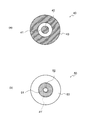
- FIG. 2 is a diagram illustrating the opening member and the light reduction member.
- Fig.2 (a) is a figure which shows an opening member.
- FIG. 2B is a diagram showing the light reducing member.
- the opening member 5 has an opening region 5a and a light shielding region 5b.
- the opening region 5a is formed so as to include the optical axis. Therefore, the illumination light passes through the opening region 5a as it is. “As it is” means a state in which almost no light reduction or light shielding occurs.
- the shape of the opening region 5a is a circle.
- the light shielding area 5b is located outside the opening area 5a.
- the light shielding area 5b is an area that prevents passage of illumination light.
- the shape of the light shielding region 5b is a ring.
- the opening member 5 can be an opaque plate or a colorless and transparent plate.
- the opaque plate include a metal plate and an opaque resin plate.
- the colorless and transparent plate include a glass plate and a transparent resin plate.
- a through hole may be formed in the opaque plate.
- the portion of the through hole becomes the opening region 5a.
- the opaque plate portion becomes the light shielding region 5b.
- a shading paint may be applied to a part of the colorless and transparent plate. In this way, a region where the light-shielding paint is not applied and a region where the light-shielding paint is applied are formed. In this case, the area where the light-shielding paint is not applied becomes the opening area 5a. Further, the area where the light-shielding paint is applied becomes the light-shielding area 5b.
- the light transmittance in the light shielding region 5b is 0%. However, if the light transmittance is low, the same effect as when the light transmittance is 0% can be obtained. Therefore, the light shielding region 5b can be replaced with a light reduction region.
- the light transmittance in the dimming region is preferably 10% or less.
- the opening member may have an opening region and a light shielding region or a light shielding region.
- the opening member 5 and the light source 1 are conjugate. Therefore, the illumination light emitted from the light source 1 is condensed at the position of the opening member 5. That is, an image of the light source 1 is formed at the position of the opening member 5.
- the illumination light emitted from the opening member 5 enters the condenser lens 4.
- the position of the aperture member 5 coincides with the focal position of the condenser lens 4 (or the pupil position of the condenser lens 4). Therefore, the illumination light emitted from the condenser lens 4 becomes parallel light.
- the opening member 5 may be disposed at the pupil position of the illumination optical system 100 or at a position conjugate with the pupil of the illumination optical system 110. Therefore, the aperture member 5 only needs to be disposed at the pupil position of the condenser lens 4 or at a position conjugate with the pupil of the condenser lens 4.
- the illumination light emitted from the condenser lens 4 reaches the sample 7.
- the specimen 7 is placed on the holding member 6.
- the specimen 7 is, for example, a cell and is colorless and transparent.
- the specimen 7 Since the illumination light emitted from the condenser lens 4 is parallel light, the specimen 7 is illuminated with parallel light. From the sample 7, zero-order diffracted light and diffracted light are generated. In FIG. 1, the zero-order diffracted light is shown by a solid line. Further, as the diffracted light, the first-order diffracted light is indicated by a broken line.
- the first-order diffracted light is incident on the objective lens 8.
- the objective lens 8 is, for example, a microscope objective lens for bright field observation. Therefore, there is only a lens in the optical path of the objective lens 8, and there is no optical member that changes the phase of light like a phase plate or an optical member that changes the intensity of light like a modulation plate. .
- the first-order diffracted light is emitted as parallel light.
- the first-order diffracted light emitted from the objective lens 8 enters the imaging lens 10.
- the first-order diffracted light is collected by the imaging lens 10.
- the first-order diffracted light collected at the image position becomes divergent light and enters the relay optical system 11.
- the relay optical system 11 includes a lens 12 and a lens 13.
- the first-order diffracted light is collimated by the lens 12 and then collected by the lens 13.
- the first-order diffracted light is collected by the relay optical system 11.
- 0th-order diffracted light also enters the objective lens 8.
- the 0th-order diffracted light incident on the objective lens 8 is collected at the position of the pupil 9 of the objective lens.
- the 0th-order diffracted light emitted from the sample 7 is parallel light, and the illumination light applied to the sample 7 is also parallel light. If the 0th-order diffracted light is regarded as illumination light, the illumination light emitted from one point of the aperture region 5a is condensed at the position of the pupil 9 of the objective lens. Thus, the pupil 9 of the objective lens and the aperture member 5 are conjugate. Therefore, an image of the aperture member 5 is formed at the position of the pupil 9 of the objective lens.
- the 0th-order diffracted light is emitted as divergent light.
- the 0th-order diffracted light emitted from the objective lens 8 enters the imaging lens 10.
- the imaging lens 10 From the imaging lens 10, the 0th-order diffracted light is emitted as parallel light.
- the 0th-order diffracted light enters the relay optical system 11.
- the 0th-order diffracted light incident on the relay optical system 11 is collected by the lens 12 and then converted into parallel light by the lens 13. As a result, the 0th-order diffracted light is emitted from the relay optical system 11 as parallel light. The 0th-order diffracted light emitted from the relay optical system 11 reaches the condensing position 15.
- an image of the sample 7 is formed by the 0th-order diffracted light and the first-order diffracted light.
- the specimen observation apparatus 100 includes a drive mechanism 16. At least one of the holding member 6 and the observation optical system 120 can be moved along the optical axis of the observation optical system 120 by the drive mechanism 16 so as to be in the first predetermined state.
- the in-focus position is a position where the wavefront aberration amount in the 0th-order diffracted light and the wavefront aberration amount in the 1st-order diffracted light are both 0 at the spatial frequency of the sample 7.
- the holding member 6 can be moved out of focus by moving the holding member 6 along the optical axis.
- a light reducing member 14 is disposed in the relay optical system 11.
- the light reducing member 14 is disposed at a position conjugate with the pupil of the observation optical system 120.
- the light reducing member 14 is disposed at a position conjugate with the pupil 9 of the objective lens.
- the dimming member 14 has a dimming area 14a and a non-dimming area 14b.
- the dimming region 14a is formed so as to include the optical axis.
- the shape of the dimming region 14a is a circle.
- the non-dimming area 14b is located outside the dimming area 14a.
- the shape of the non-light-reducing region 14b is a ring.
- the light transmittance in the dimming region 14a is smaller than the light transmittance in the non-dimming region 14b. Further, the light transmittance in the dimming region 14a is the same at any position within the region. The light transmittance in the non-dimming region 14b is also the same at any position in the region.
- Dimming can be performed by reflection only, absorption only, or both reflection and absorption.
- a dielectric multilayer filter may be used.
- a colored glass filter or an absorption ND filter may be used.
- the dielectric multilayer filter a multilayer film is formed on the surface of a colorless and transparent member.
- the reflectance characteristic (or transmittance characteristic) is determined by the multilayer structure (thin film thickness, thin film material, total number of thin films, etc.).
- the absorptance is determined by the color density of the colorless and transparent member.
- the absorption rate is determined by the light absorption effect of the substrate.
- the light reducing member 14 can be an opaque plate or a colorless and transparent plate. Examples of the opaque plate and the colorless and transparent plate are as described above.
- a through hole may be formed in the opaque plate.
- the portion of the through hole becomes the dimming region 14a.
- a dielectric multilayer film is formed on a colorless and transparent plate, and the colorless and transparent plate may be positioned in the through hole.
- the colored glass may be positioned in the through hole.
- the dimming region 14a may be formed on a part of the colorless and transparent plate.
- a dielectric multilayer film When dimming by reflection, a dielectric multilayer film may be formed on a part of a colorless and transparent plate. Thus, a region where the dielectric multilayer film is formed and a region where the dielectric multilayer film is not formed are formed. The region where the dielectric multilayer film is formed becomes the dimming region 14a. In addition, a region where the dielectric multilayer film is not formed becomes a non-light-reducing region 14b.
- colored glass may be placed on a part of a colorless and transparent plate. Alternatively, a part of the colorless and transparent plate may be replaced with colored glass. If it does in this way, the area
- the light reducing member 14 is disposed between the lens 12 and the lens 13. More specifically, the dimming member 14 is disposed at the condensing position of the 0th-order diffracted light.
- the opening region 5a is formed so as to include the optical axis. Therefore, the 0th-order diffracted light travels along the optical path of the observation optical system 120 so as to include the optical axis.
- the dimming region 14a is formed so as to include the optical axis. Therefore, the 0th-order diffracted light passes through the dimming region 14a. As a result, the 0th-order diffracted light is attenuated in the dimming region 14a.
- the non-dimming region 14b is located outside the dimming region 14a. Therefore, the first-order diffracted light passes as it is in the non-attenuating region 14b.
- the 0th-order diffracted light is attenuated in the dimming region 14a means that the value of A 1 becomes small.
- the value of 2A 2 cos ⁇ does not change.
- the value of the denominator in the above formula becomes small, the value of C becomes large. That is, the contrast of the image in the out-of-focus state increases.
- an image of the aperture member is formed in the dimming region of the dimming member, and the dimming region of the dimming member is formed so as to include the image of the aperture member.
- the light intensity in the 0th-order diffracted light is very large compared to the light intensity in the 1st-order diffracted light. For this reason, the presence of 0th-order diffracted light that does not pass through the dimming region 14a reduces the image contrast. Therefore, it is preferable that the 0th-order diffracted light is attenuated as much as possible in the dimming region 14a.
- the size of the image 5a 'of the opening area varies depending on various factors. For example, when a specimen in a liquid is observed, a lens effect is generated depending on the liquid level. As a result, the size of the image 5a 'of the opening area changes. Further, for example, the size of the image 5a 'of the opening region changes due to the position of the opening member or the position of the light reducing member being deviated from the original position.
- the dimming member is disposed at a position conjugate with the opening member. Therefore, an image of the aperture member is formed in the light reduction region of the light reduction member.
- the dimming region 14a includes the image 5a 'of the opening region. In this way, even if the size of the image 5a 'in the aperture region changes, the 0th-order diffracted light can pass through the dimming region 14a. As a result, it is possible to obtain an image of a specimen having a high contrast in the out-of-focus state.
- FIG. 3 shows a first example of an opening member and a light reducing member.
- Fig.3 (a) is a figure which shows the 1st example of an opening member.
- FIG. 3B is a diagram illustrating a first example of the light reducing member.
- the opening member 20 of the first example has an opening region 21 and a light shielding region 22.
- the opening region 21 is formed so as to include the optical axis.
- the shape of the opening region 21 is a circle.
- the light shielding area 22 is located outside the opening area 21.
- the shape of the light shielding region 22 is a ring.
- the light-reducing member 30 of the first example has a light-reducing area 31 and a non-light-reducing area 32.
- the dimming region 31 is formed so as to include the optical axis.
- the shape of the dimming region 31 is a circle.
- the dimming area 31 is formed so as to include an image 21 'of the opening area.
- the non-dimming area 32 is located outside the dimming area 31.
- the shape of the non-light-reducing region 32 is a ring.
- the light transmittance in the light reducing region 31 is smaller than the light transmittance in the non-light reducing region 32.
- the light transmittance in the dimming region 31 varies depending on the position in the region.
- the light transmittance is the smallest at the center, and the light transmittance increases as it approaches the non-dimming region 32.
- the light transmittance in the non-dimming region 32 is the same at any position within the region.
- the opening region 21 is formed so as to include the optical axis. Therefore, the 0th-order diffracted light travels along the optical path of the observation optical system so as to include the optical axis.
- the dimming region 31 is also formed so as to include the optical axis. Therefore, the 0th-order diffracted light passes through the dimming region 31. As a result, the 0th-order diffracted light is attenuated in the dimming region 31.
- the non-dimming area 32 is located outside the dimming area 31. Therefore, in the non-attenuating region 32, the first-order diffracted light passes as it is.
- FIG. 4 shows a second example of the opening member and the dimming member.
- Fig.4 (a) is a figure which shows the 2nd example of an opening member.
- FIG. 4B is a diagram illustrating a second example of the light reducing member.
- the opening member 40 of the second example has an opening area 41, a light shielding area 42, and a light shielding area 43.
- the opening region 41 is formed so as not to include the optical axis.
- the shape of the opening region 41 is a ring.
- the light shielding area 42 is located inside the opening area 41.
- the shape of the light shielding region 42 is a circle.
- the light shielding area 43 is located outside the opening area 41.
- the shape of the light shielding region 43 is a ring.
- the light-reducing member 50 of the second example has a light-reducing area 51, a non-light-reducing area 52, and a non-light-reducing area 53.
- the dimming region 51 is formed so as not to include the optical axis.
- the shape of the dimming region 51 is a ring.
- the dimming area 51 is formed so as to include an image 41 'of the opening area.
- the non-dimming area 52 is located inside the dimming area 51.
- the shape of the non-dimming region 52 is a circle.
- the non-dimming area 53 is located outside the dimming area 51.
- the shape of the non-light-reducing region 52 is a ring.
- the light transmittance in the light-reducing region 51 is smaller than the light transmittance in the non-light-reducing region 52 and the light transmittance in the non-light-reducing region 52.
- the light transmittance in the dimming region 51 is the same at any position in the region.
- the light transmittance in the non-light-reducing region 52 and the light transmittance in the non-light-reducing region 52 are the same at any position in the region.
- the opening region 41 is formed so as not to include the optical axis. Therefore, the 0th-order diffracted light travels along the optical path of the observation optical system so as not to include the optical axis.
- the dimming region 51 is also formed so as not to include the optical axis. Therefore, the 0th-order diffracted light passes through the dimming region 51. As a result, the 0th-order diffracted light is attenuated in the dimming region 51.
- the non-dimming area 52 is located inside the dimming area 51, and the non-dimming area 53 is located outside the dimming area 51. Therefore, the first-order diffracted light passes through the non-dimming region 52 and the non-dimming region 53 as it is.
- the shape of the opening area and the shape of the dimming area of the dimming member are not limited to a circle or a ring.
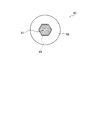
- FIG. 5 is a diagram illustrating another example of the dimming member.
- the light reducing member 60 has a light reducing region 61 and a non-light reducing region 62.
- the dimming region 61 is formed so as to include the optical axis.
- the dimming area 61 has a polygonal shape.
- the dimming area 61 is formed so as to include an image 63 of the opening area.
- the non-dimming area 62 is located outside the dimming area 61.
- the non-light-reducing region 62 has a polygonal inner edge and a circular outer edge.
- the light transmittance in the dimming region 61 is smaller than the light transmittance in the non-dimming region 62.
- the light transmittance in the dimming region 61 is the same at any position in the region.
- the light transmittance in the non-dimming region 62 is the same at any position in the region.
- An opening region (not shown) corresponding to the light reduction region 61 is formed so as to include the optical axis. Therefore, the 0th-order diffracted light travels along the optical path of the observation optical system so as to include the optical axis.
- the dimming region 61 is also formed so as to include the optical axis. Therefore, the 0th-order diffracted light passes through the dimming region 61. As a result, the 0th-order diffracted light is attenuated in the dimming region 61.
- the non-dimming area 62 is located outside the dimming area 61. Therefore, in the non-attenuating region 62, the first-order diffracted light passes as it is.
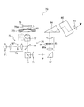
- FIG. 6 is a diagram showing a configuration of another specimen observation apparatus of the present embodiment.
- the sample observation device 70 is, for example, a device using an inverted microscope.
- the specimen observation device 70 includes a light source 71, an illumination optical system 72, a stage 73, an imaging optical system 74, and a reflection member 75.
- the light source 71 is located in the downward direction in the drawing with respect to the stage 73. Illumination light is emitted from the light source 71.
- the light source 71 for example, a halogen lamp, a xenon lamp, a mercury lamp, a laser, a light emitting diode, or the like is used.
- the illumination light emitted from the light source 71 enters the illumination optical system 72.
- the illumination optical system 72 is positioned in the downward direction in the drawing with respect to the stage 73.
- the illumination optical system 72 includes a condensing optical system 76 and an objective lens 77.
- the objective lens 77 constitutes an imaging optical system 74 in combination with the imaging lens 78.
- the objective lens 77 is used in common by the illumination optical system 72 and the imaging optical system 74.
- the condensing optical system 76 is composed of two lenses, but the number of lenses is not limited to two.
- the condensing optical system 76 may include an optical filter and an optical aperture.
- the illumination light passes through the condensing optical system 76 and enters the half mirror 79. Subsequently, the illumination light is reflected by the half mirror 79 and enters the objective lens 77. The illumination light that has passed through the objective lens 77 reaches the stage 73.
- the illumination light passes through the opening formed in the stage 73.
- the specimen S held in the container 80 is placed on the opening of the stage 73. Therefore, the illumination light is irradiated to the sample S through the opening of the stage 73.
- the sample S is colorless and transparent, the sample S is irradiated and the illumination light passes through the sample S.
- the illumination light that has passed through the sample S enters the reflecting member 75.
- the reflecting member 75 is arranged in the upward direction in the drawing with respect to the stage 73.
- a light source 71 and an imaging optical system 74 are arranged on the illumination optical system 72 side. Therefore, the reflecting member 75 is disposed at a position facing the imaging optical system 74 with the stage 73 interposed therebetween.
- the reflection member 75 is, for example, a parallel plate having a reflection film 75a formed on the surface.
- the reflection member 75 is disposed on the sample S.
- the reflective member 75 is disposed so that the surface on which the reflective film 75a is formed faces the stage 73 side.
- the illumination light transmitted through the specimen S is reflected by the reflecting member 75, and the reflected illumination light is irradiated again on the specimen S. As a result, transmitted illumination is performed on the specimen S.
- the specimen observation device 70 can perform the transmission illumination on the specimen S similarly to the transmission illumination in the conventional microscope.
- the light from the sample S enters the imaging optical system 74.
- the imaging optical system 74 includes an objective lens 77 and an imaging lens 78.
- Light from the specimen S passes through the objective lens 77 and the half mirror 79 and is collected by the imaging lens 78.
- the position of the sample S coincides with the in-focus position of the imaging optical system 74.
- an image of the sample S is clearly formed at the position P collected by the imaging lens 78. That is, an image of the focused sample S is formed at the position P.
- the sample observation device 70 further includes a prism 81, a prism 82, a relay optical system 83, a prism 84, a binocular division prism 85, and an eyepiece 86.
- the light from the specimen S passes through the objective lens 77 and the half mirror 79 and enters the prism 81.
- the light reflected by the prism 81 is collected by the imaging lens 78.
- an optical image having a contrast at the position P is formed.
- the light from the optical image of the sample S is reflected by the mirror surface of the prism 82, passes through the relay optical system 83 and the prism 84, and enters the binocular division prism 85.
- the binocular splitting prism 85 forms a right-eye optical path and a left-eye optical path.
- An eyepiece 86 is disposed in each of the optical path for the right eye and the optical path for the left eye.
- the image of the sample S is relayed by the relay optical system 83, and the relayed image of the sample S is formed in the vicinity of the eyepiece lens 86. Thereby, the observer can observe the image of the sample S with both eyes.
- the sample S When the sample S is colorless and transparent, for example, in the case of a living cell, the sample S has no contrast. Therefore, in the state where the position of the sample S coincides with the in-focus position of the imaging optical system 74, the contrast of the image of the sample S formed at the position P does not occur. Therefore, the specimen S cannot be observed.
- an image of the specimen S is obtained in an out-of-focus state, that is, in a state where the position of the specimen S is different from the in-focus position of the imaging optical system 74 (hereinafter referred to as “focus position”).
- the objective lens 77 may be moved by eye measurement to a position that seems to be deviated from the in-focus position.
- the in-focus position and the position of the sample S may be matched, and then the objective lens 77 may be moved in a direction away from the in-focus position.
- a position shifted from the in-focus position can be determined in advance, and the objective lens 77 may be moved to that position.
- stage 73 If the stage 73 is movable, the stage 73 may be moved. Further, both the objective lens 77 and the stage 73 may be moved.
- the objective lens 77 is indicated by a broken line and a solid line.
- the position indicated by the broken line is the position of the objective lens 77 when the position of the sample S and the in-focus position match.
- the position indicated by the solid line is the position of the objective lens 77 when the position of the sample S is different from the focus position.
- the objective lens 77 is moved from the position indicated by the broken line to the position indicated by the solid line, so that the position of the sample S is different from the in-focus position.
- the difference between the position indicated by the solid line and the position indicated by the broken line is exaggerated so that the movement of the objective lens 77 can be seen, but the actual movement amount is slight.
- the direction in which the objective lens 77 is moved may be either the direction approaching the stage 73 or the direction away from the stage 73.
- the image of the sample S is formed by the zero-order diffracted light and the first-order diffracted light at the condensing position 15 where the first-order diffracted light is collected.
- an aperture member 87 is disposed at the position of the pupil of the illumination optical system 72, and a light reducing member 88 is disposed at a position conjugate with the pupil of the imaging optical system 74. Therefore, it is possible to obtain an image of a specimen having a high contrast in the out-of-focus state.
- T is the light transmittance in the light shielding region of the light reducing member, It is.
- conditional expression (1) If the lower limit of conditional expression (1) is not reached, the light intensity in the 0th-order diffracted light becomes too small. This makes it difficult to obtain a bright image. When an image is picked up by the image pickup device, the image pickup time becomes too long.
- a structure having a double spatial frequency is a structure that does not originally exist in the specimen.
- conditional expression (1) If the upper limit of conditional expression (1) is exceeded, the light intensity in the 0th-order diffracted light becomes too large. As a result, the contrast of the image decreases.
- NAill is the numerical aperture on the specimen side of the illumination optical system
- NA ob is the numerical aperture on the specimen side of the imaging optical system
- conditional expression (2) If the upper limit of conditional expression (2) is exceeded, the numerical aperture on the specimen side of the illumination optical system becomes too large. In this case, the illumination light incident obliquely with respect to the optical axis increases. This makes it difficult to obtain an electronic image with good contrast.
- conditional expression (3) 0.05 ⁇ m ⁇ Z ⁇ NA ill ⁇ 10 ⁇ m (3) here, ⁇ Z is the difference between the focusing position of the imaging optical system and the position of the sample, NAill is the numerical aperture on the specimen side of the illumination optical system, It is.
- the lower limit of conditional expression (3) If the lower limit of conditional expression (3) is not reached, the difference between the focusing position of the imaging optical system and the position of the sample becomes too small. In this case, the amount of wavefront aberration added to the diffracted light is reduced. In particular, the amount of wavefront aberration added to the first-order diffracted light is smaller than ⁇ / 4. This makes it difficult to obtain an electronic image with good contrast.
- conditional expression (3) If the upper limit value of conditional expression (3) is exceeded, the difference between the focusing position of the imaging optical system and the position of the sample becomes too large. In this case, the amount of wavefront aberration added to the diffracted light increases. In particular, the amount of wavefront aberration added to the first-order diffracted light becomes larger than ⁇ / 4. In addition, the optical image is greatly blurred. As a result, it is difficult to obtain an electronic image with high resolution.
- conditional expression (3) if the upper limit of conditional expression (3) is exceeded, the numerical aperture on the specimen side of the illumination optical system becomes too large. In this case, the illumination light incident obliquely with respect to the optical axis increases. This makes it difficult to obtain an electronic image with good contrast.
- ⁇ Z is the difference between the focusing position of the imaging optical system and the position of the sample
- NA ob is the numerical aperture on the specimen side of the imaging optical system
- the lower limit of conditional expression (4) If the lower limit of conditional expression (4) is not reached, the difference between the focusing position of the imaging optical system and the position of the sample becomes too small. In this case, the amount of wavefront aberration added to the diffracted light is reduced. In particular, the amount of wavefront aberration added to the first-order diffracted light is smaller than ⁇ / 4. This makes it difficult to obtain an electronic image with good contrast.
- the upper limit (4) of the conditional expression If the upper limit (4) of the conditional expression is exceeded, the difference between the focusing position of the imaging optical system and the position of the sample becomes too large. In this case, the amount of wavefront aberration added to the diffracted light increases. In particular, the amount of wavefront aberration added to the first-order diffracted light becomes larger than ⁇ / 4. In addition, the optical image is greatly blurred. As a result, it is difficult to obtain an electronic image with high resolution.
- the dimming member moves in an in-plane direction orthogonal to the optical axis.
- the light-reducing area of the light-reducing member can be in a state that includes the image of the opening member.
- the position of the opening region changes due to the lens effect due to the shape of the specimen and the lens effect due to the liquid level during specimen observation in liquid. Even in such a case, the light-reducing area of the light-reducing member can be in a state including the image of the opening member.
- the shape of the opening region and the shape of the dimming region of the dimming member are rotationally symmetric shapes.
- the illumination light is applied to the sample so that the light beam intersects the optical axis at the sample position. Therefore, when the shape of the opening region is a non-rotationally symmetric shape, the illumination is considered to be oblique illumination. In the oblique illumination, an image shift corresponding to the defocus amount from the in-focus state occurs in the out-of-focus state. By making the shape of the aperture region rotationally symmetric, it is possible to eliminate image shift in an out-of-focus state.
- the dimming member is preferably arranged so that the normal of the surface of the dimming member intersects the optical axis.
- the present invention is suitable for a specimen observation apparatus capable of obtaining a specimen image having a large contrast in an out-of-focus state.
Landscapes
- Physics & Mathematics (AREA)
- Chemical & Material Sciences (AREA)
- Analytical Chemistry (AREA)
- General Physics & Mathematics (AREA)
- Optics & Photonics (AREA)
- Microscoopes, Condenser (AREA)
Abstract
非合焦状態において、コントラストが大きい標本の像を得ることが可能な標本観察装置を提供する。 標本観察装置100は、照明光学系110と、観察光学系120と、標本保持部材6と、を備え、照明光学系110は、コンデンサレンズ4と、開口部材5と、を有し、観察光学系120は、対物レンズ8と、減光部材14と、結像レンズ10と、を有し、開口部材5は、照明光学系110の瞳位置に配置されるか、又は、照明光学系110の瞳と共役な位置に配置され、減光部材14は、観察光学系120の瞳と共役な位置に配置され、開口部材5は、開口領域5aを有し、減光部材14は、減光領域14aを有し、駆動機構16は、第1の所定の状態となるように、標本保持部材6及び観察光学系120の少なくとも1つを移動させ、第1の所定の状態では、標本7の位置と観察光学系120の合焦位置とが異なっている。
Description
本発明は、標本観察装置に関する。
標本を平行光束で照明すると、標本からは、非回折光(以下、0次回折光という)と回折光が生じる。顕微鏡では、標本の像は、0次回折光と回折光の合成によって形成される。
像面における複素振幅Eは、例えば、以下の式で表される。
E=A1e-iφ1(r)eiωt+A2e-iφ2(r)eiωt
ここで、
A1は0次回折光の振幅、
A2は回折光の振幅、
φ1(r)は0次回折光の位相、
φ2(r)は回折光の位相、
である。
E=A1e-iφ1(r)eiωt+A2e-iφ2(r)eiωt
ここで、
A1は0次回折光の振幅、
A2は回折光の振幅、
φ1(r)は0次回折光の位相、
φ2(r)は回折光の位相、
である。
像面では光の強度が観測されるため、像面における光の強度Iは以下の式で表される。
I=|E|2=A1 2+A2 2+2A1A2cosψ
ここで、
ψは位相差であって、ψ=φ1(r)-φ2(r)、
である。
I=|E|2=A1 2+A2 2+2A1A2cosψ
ここで、
ψは位相差であって、ψ=φ1(r)-φ2(r)、
である。
上述のように、標本の像(光学像)の形成には、0次回折光と回折光が必要である。そこで、以下の説明では、0次回折光と1次回折光とによって、標本の像(光学像)が形成されるものとする。
標本が位相物体の場合、位相物体で、0次回折光、1次回折光及び高次の回折光が生じる。1次回折光の位相は、0次回折光の位相に対してπ/2遅れている。よって、ψ=π/2となる。
また、標本が細胞のような弱位相物体の場合、弱位相物体では、1次回折光における光の強度は、0次回折光における光の強度に比べて十分に小さい。すなわち、標本が弱位相物体の場合、A1>>A2になる。
A2
2の値は、A1
2の値と比べて十分に小さいので、A2
2の値は無視されてしまう。標本が弱位相物体の場合、光の強度Iを表す式においてA2の項が消える。この時、標本の位置と合焦位置とが一致している状態(以下、「合焦状態」という)では、ψ=π/2により、2A1A2cosψ=0になる。その結果、合焦状態では、像面における光の強度Iは、以下のようになる。
I=|E|2=A1 2+A2 2+2A1A2cosψ≒A1 2
A1 2は、0次光における光の強度、すなわち、背景光における光の強度を表している。このように、標本が弱位相物体の場合、合焦状態では、背景光だけが得られることになる。
I=|E|2=A1 2+A2 2+2A1A2cosψ≒A1 2
A1 2は、0次光における光の強度、すなわち、背景光における光の強度を表している。このように、標本が弱位相物体の場合、合焦状態では、背景光だけが得られることになる。
像のコントラストは、以下の式で表される。
C=2A1A2cosψ/(A1 2+2A1A2cosψ)
上述のように、標本が弱位相物体の場合、A1>>A2になり、また、合焦状態ではA1A2cosψ=0になる。よって、合焦状態では、像のコントラストは、以下のようになる。
C=0/A1 2=0
C=2A1A2cosψ/(A1 2+2A1A2cosψ)
上述のように、標本が弱位相物体の場合、A1>>A2になり、また、合焦状態ではA1A2cosψ=0になる。よって、合焦状態では、像のコントラストは、以下のようになる。
C=0/A1 2=0
このように、標本が弱位相物体の場合、合焦状態では、コントラストはC=0になるので、標本の像にコントラストは生じない。よって、標本の像を得ることができない。
標本の位置が合焦位置からずれている状態(以下、「非合焦状態」という)では、0次回折光と回折光との間に波面収差の差(光路長差)が発生する。ここでは、1次回折光の光路長が、0次回折光の光路長に対してλ/4ほど長くなるとする。この場合、像位置では、1次回折光の位相は、0次回折光の位相に対してπほど遅れることになる。
その結果、非合焦状態では、像面における光の強度Iは、以下のようになる。
I=|E|2=A1 2+A2 2+2A1A2cosψ≒A1 2+2A1A2cosψ
I=|E|2=A1 2+A2 2+2A1A2cosψ≒A1 2+2A1A2cosψ
上述のように、A1
2は、背景光における光の強度を表している。一方、2A1A2cosψは、像の光の強度を表している。このように、標本が弱位相物体の場合、非合焦状態では、標本の像が得られることになる。
非合焦状態では、像のコントラストは、以下のようになる。
C=2A1A2cosψ/(A1 2+2A1A2cosψ)=2A2cosψ/(A1+2A2cosψ)
C=2A1A2cosψ/(A1 2+2A1A2cosψ)=2A2cosψ/(A1+2A2cosψ)
このように、標本が弱位相物体であっても、非合焦状態にすると、標本の像にコントラストが生じる。よって、標本の像を得ることができる。
非特許文献1には、コントラストを持つ像を得る方法が開示されている。非特許文献1では、標本は、無染色細胞のような位相物体である。このような標本をコヒーレント光で照明すると、合焦状態では標本の像コントラストの値が最小になり、非合焦状態ではコントラストの値が大きくなる。非特許文献1では、このような現象を利用して、コントラストを持つ標本の像を得ている。
U.AGERO ET AL, "Cell surface fluctuations studied with defocusing microscopy",PHYSICAL REVIEW E,2003年
標本をコヒーレント光で照明した場合であっても、A1>>A2になる。そのため、非特許文献1に開示されている方法を用いても、コントラストが大きい標本の像を得ることは難しい。
本発明は、上記に鑑みてなされたものであって、非合焦状態において、コントラストが大きい標本の像を得ることが可能な標本観察装置を提供することを目的とする。
上述した課題を解決し、目的を達成するために、本発明の標本観察装置は、
照明光学系と、観察光学系と、標本保持部材と、を備え、
照明光学系は、光源と、コンデンサレンズと、開口部材と、を有し、
観察光学系は、対物レンズと、減光部材と、結像レンズと、駆動機構と、を有し、
開口部材は、照明光学系の瞳位置に配置されるか、又は、照明光学系の瞳と共役な位置に配置され、
減光部材は、観察光学系の瞳と共役な位置に配置され、
開口部材は、開口領域と、遮光領域又は減光領域と、を有し、
減光部材は、減光領域と、非減光領域と、を有し、
非減光領域は、減光部材の減光領域の光透過率よりも高い光透過率を有し、
駆動機構は、第1の所定の状態となるように、標本保持部材及び観察光学系の少なくとも1つを、観察光学系の光軸に沿って移動させ、
第1の所定の状態では、標本保持部材上の標本の位置と観察光学系の合焦位置とが異なっていることを特徴とする。
照明光学系と、観察光学系と、標本保持部材と、を備え、
照明光学系は、光源と、コンデンサレンズと、開口部材と、を有し、
観察光学系は、対物レンズと、減光部材と、結像レンズと、駆動機構と、を有し、
開口部材は、照明光学系の瞳位置に配置されるか、又は、照明光学系の瞳と共役な位置に配置され、
減光部材は、観察光学系の瞳と共役な位置に配置され、
開口部材は、開口領域と、遮光領域又は減光領域と、を有し、
減光部材は、減光領域と、非減光領域と、を有し、
非減光領域は、減光部材の減光領域の光透過率よりも高い光透過率を有し、
駆動機構は、第1の所定の状態となるように、標本保持部材及び観察光学系の少なくとも1つを、観察光学系の光軸に沿って移動させ、
第1の所定の状態では、標本保持部材上の標本の位置と観察光学系の合焦位置とが異なっていることを特徴とする。
本発明によれば、非合焦状態において、コントラストが大きい標本の像を得ることが可能な標本観察装置を提供できる。
本発明のある態様にかかる実施形態の作用効果を説明する。なお、本実施形態の作用効果を具体的に説明するに際しては、具体的な例を示して説明することになる。しかし、それらの例示される態様はあくまでも本発明に含まれる態様のうちの一部に過ぎず、その態様には数多くのバリエーションが存在する。したがって、本発明は例示される態様に限定されるものではない。
実施形態の標本観察装置について説明する。本実施形態の標本観察装置は、明視野観察の状態で用いられるものである。本実施形態の標本観察装置を用いた明視野観察では、蛍光観察のように、励起フィルタ、ダイクロイックミラー、吸収フィルタからなる蛍光ミラーユニットは用いられない。よって、明視野観察の状態では、標本が無色透明の場合、標本像を形成する光(以下、適宜、「結像光」という)の波長帯域は、標本を照明する光(以下、適宜、「照明光」という)の波長帯域のうちの一部と一致しているか、又は結像光の波長帯域と照明光の波長帯域とは一致している。
また、本実施形態の標本観察装置における明視野観察では、位相差観察における位相膜や、微分干渉観察における微分干渉プリズムは用いられない。また、本実施形態の標本観察装置における明視野観察では、変調コントラスト観察における変調器は用いられない。
本実施形態の標本観察装置は、照明光学系と、観察光学系と、標本保持部材と、を備え、照明光学系は、光源と、コンデンサレンズと、開口部材と、を有し、観察光学系は、対物レンズと、減光部材と、結像レンズと、駆動機構と、を有し、開口部材は、照明光学系の瞳位置に配置されるか、又は、照明光学系の瞳と共役な位置に配置され、減光部材は、観察光学系の瞳と共役な位置に配置され、開口部材は、開口領域と、遮光領域又は減光部材と、を有し、減光部材は、減光領域と、非減光領域と、を有し、非減光領域は、減光部材の減光領域の光透過率よりも高い光透過率を有し、駆動機構は、第1の所定の状態となるように、標本保持部材及び観察光学系の少なくとも1つを、観察光学系の光軸に沿って移動させ、第1の所定の状態では、標本保持部材上の標本の位置と観察光学系の合焦位置とが異なっていることを特徴とする。
本実施形態の標本観察装置について、図1を用いて説明する。図1は本実施形態の標本観察装置の構成を示す図である。
標本観察装置100は、例えば、正立型顕微鏡であって、照明光学系110と観察光学系120とを備える。照明光学系110は、光源1と、コンデンサレンズ4と、開口部材5と、を有する。なお、必要に応じて、照明光学系110は、レンズ2やレンズ3を有する。一方、観察光学系は、対物レンズ8と、結像レンズ10と、を有する。
光源1から出射した光は、レンズ2とレンズ3を通過して、コンデンサレンズ4に到達する。コンデンサレンズ4には、開口部材5が設けられている。ここでは、コンデンサレンズ4と開口部材5とが、一体で構成されている。しかしながら、開口部材5とコンデンサレンズ4とを、それぞれ別体で構成しても良い。
開口部材について説明する。図2は、開口部材と減光部材を示す図である。図2(a)は、開口部材を示す図である。図2(b)は、減光部材を示す図である。
図2(a)に示すように、開口部材5は、開口領域5aと、遮光領域5bと、を有する。開口領域5aは、光軸を含むように形成されている。よって、開口領域5aでは、照明光がそのまま通過する。「そのまま」とは、減光や遮光が、ほとんど生じていない状態を意味する。開口領域5aの形状は、円である。
遮光領域5bは、開口領域5aの外側に位置する。遮光領域5bは、照明光の通過を阻止する領域である。遮光領域5bの形状は、円環である。
開口部材5には、不透明な板、又は、無色透明な板を用いることができる。不透明な板としては、例えば、金属板や不透明な樹脂板がある。無色透明な板としては、例えば、ガラス板や透明な樹脂板がある。
不透明な板を用いる場合は、不透明な板に貫通孔を形成すれば良い。この場合、貫通孔の部分が、開口領域5aになる。また、不透明な板の部分が、遮光領域5bになる。
無色透明な板を用いる場合は、無色透明な板の一部に遮光塗料を塗布すれば良い。このようにすると、遮光塗料が塗布されていない領域と、遮光塗料が塗布されている領域と、が形成される。この場合、遮光塗料が塗布されない領域が、開口領域5aになる。また、遮光塗料が塗布されている領域が、遮光領域5bになる。
遮光領域5bでは光の透過は生じないので、遮光領域5bにおける光透過率は0%である。ただし、光透過率が低ければ、光透過率が0%の場合と同じ効果が得られる。よって、遮光領域5bは、減光領域に置き換えることができる。減光領域における光透過率は10%以下であることが好ましい。このように、開口部材は、開口領域と、遮光領域又は遮光領域と、を有するようにしても良い。
図1に戻って説明を続ける。開口部材5と光源1とは共役になっている。よって、光源1から出射した照明光は、開口部材5の位置で集光する。すなわち、開口部材5の位置に光源1の像が形成される。
開口部材5から出射した照明光は、コンデンサレンズ4に入射する。ここで、開口部材5の位置は、コンデンサレンズ4の焦点位置(あるいは、コンデンサレンズ4の瞳位置)と一致している。そのため、コンデンサレンズ4から出射する照明光は、平行光になる。
開口部材5は、照明光学系100の瞳位置に配置されるか、又は、照明光学系110の瞳と共役な位置に配置されていれば良い。よって、開口部材5は、コンデンサレンズ4の瞳位置、又は、コンデンサレンズ4の瞳と共役な位置に配置されていれば良い。
コンデンサレンズ4から出射した照明光は、標本7に到達する。標本7は保持部材6上に載置されている。標本7は、例えば細胞であって、無色透明である。
コンデンサレンズ4から出射する照明光は平行光なので、標本7は平行光で照明される。標本7からは、0次回折光と回折光とが生じる。図1では、0次回折光が、実線で示されている。また、回折光として、1次回折光が破線で示されている。
1次回折光は、対物レンズ8に入射する。対物レンズ8は、例えば、明視野観察用の顕微鏡対物レンズである。よって、対物レンズ8の光路中にはレンズが存在するだけで、位相板のように光の位相を変化させる光学部材や、変調板のように光の強度を変化させる光学部材は存在していない。
対物レンズ8からは、1次回折光が平行光になって出射する。対物レンズ8から出射した1次回折光は、結像レンズ10に入射する。1次回折光は、結像レンズ10で集光される。
像位置に集光された1次回折光は、発散光となってリレー光学系11に入射する。リレー光学系11は、レンズ12とレンズ13とで構成されている。1次回折光はレンズ12で平行光にされた後、レンズ13で集光される。このように、1次回折光は、リレー光学系11で集光される。
一方、0次回折光も、対物レンズ8に入射する。対物レンズ8に入射した0次回折光は、対物レンズの瞳9の位置で集光する。
標本7から出射したときの0次回折光は平行光で、標本7に照射されている照明光も平行光である。0次回折光を照明光と見なすと、開口領域5aの一点から出射した照明光は、対物レンズの瞳9の位置で集光している。このように、対物レンズの瞳9と開口部材5とは共役になっている。よって、対物レンズの瞳9の位置に開口部材5の像が形成される。
対物レンズ8からは、0次回折光が発散光になって出射する。対物レンズ8から出射した0次回折光は、結像レンズ10に入射する。結像レンズ10からは、0次回折光が平行光になって出射する。0次回折光は、リレー光学系11に入射する。
リレー光学系11に入射した0次回折光は、レンズ12で集光された後、レンズ13で平行光にされる。その結果、0次回折光は、平行光となってリレー光学系11から出射する。リレー光学系11から出射した0次回折光は、集光位置15に到達する。
1次回折光が集光された集光位置15では、0次回折光と1次回折光とによって標本7の像が形成される。
標本観察装置100は、駆動機構16を備えている。駆動機構16によって、第1の所定の状態となるように、保持部材6及び観察光学系120の少なくとも1つを、観察光学系120の光軸に沿って移動させることができる。
第1の所定の状態では、保持部材6上の標本7の位置と観察光学系120の合焦位置とが異なっている。これは、上述の非合焦状態と同じである。合焦位置とは、標本7の持つ空間周波数において、0次回折光における波面収差量と1次回折光における波面収差量とが共に0となる位置のことである。
上述のように、非合焦状態にすると、標本の像にコントラストが生じる。標本観察装置100でも、保持部材6を光軸に沿って移動させることで、非合焦状態にすることができる。
更に、標本観察装置100では、リレー光学系11中に、減光部材14が配置されている。減光部材14は、観察光学系120の瞳と共役な位置に配置されている。標本観察装置100では、減光部材14は、対物レンズの瞳9と共役な位置に配置されている。
図2(b)に示すように、減光部材14は、減光領域14aと非減光領域14bとを有する。減光領域14aは、光軸を含むように形成されている。減光領域14aの形状は、円である。
非減光領域14bは、減光領域14aの外側に位置する。非減光領域14bの形状は、円環である。
減光領域14aにおける光透過率は、非減光領域14bにおける光透過率よりも小さい。また、減光領域14aにおける光透過率は、領域内のどの位置でも同一になっている。非減光領域14bにおける光透過率も、領域内のどの位置でも同一になっている。
減光は、反射のみ、吸収のみ、又は、反射と吸収の両方によって行うことができる。反射による減光では、例えば、誘電体多層膜フィルタを用いれば良い。吸収による減光では、例えば、色ガラスフィルタや吸収型NDフィルタを用いれば良い。
誘電体多層膜フィルタでは、無色透明な部材の表面に、多層膜が形成されている。誘電体多層膜フィルタでは、多層膜の構造(薄膜の厚み、薄膜の材料、薄膜の総数等)によって、反射率特性(又は透過率特性)が決まる。色ガラスフィルタでは、無色透明な部材に着色した色の濃度によって、吸収率が決まる。吸収型NDフィルタでは、基板の光吸収作用によって、吸収率が決まる。
減光部材14には、不透明な板、又は、無色透明な板を用いることができる。不透明な板と無色透明な板の例は、上述したとおりである。
不透明な板を用いる場合は、不透明な板に貫通孔を形成すれば良い。この場合、貫通孔の部分が、減光領域14aになる。ただし、貫通孔で減光を行う必要がある。
反射による減光を貫通孔で行う場合は、無色透明な板に誘電体多層膜を形成し、この無色透明な板を貫通孔に位置させれば良い。貫通孔で吸収による減光を行う場合は、色ガラスを貫通孔に位置させれば良い。
無色透明な板を用いる場合は、無色透明な板の一部に減光領域14aを形成すれば良い。
反射による減光を行う場合は、無色透明な板の一部に誘電体多層膜を形成すれば良い。このようにすると、誘電体多層膜が形成されている領域と、誘電体多層膜が形成されていない領域と、が形成される。誘電体多層膜が形成されている領域が、減光領域14aになる。また、誘電体多層膜が形成されていない領域が、非減光領域14bになる。
吸収による減光を行う場合は、無色透明な板の一部に色ガラスを載置すれば良い。又は、無色透明な板の一部を色ガラスに置換すれば良い。このようにすると、色ガラスが存在する領域と、色ガラスが存在しない領域と、が形成される。色ガラスが存在する領域が、減光領域14aになる。また、色ガラスが存在しない領域が、非減光領域14bになる。
標本観察装置100では、減光部材14は、レンズ12とレンズ13との間に配置されている。より詳しくは、減光部材14は、0次回折光の集光位置に配置されている。
上述のように、開口領域5aは、光軸を含むように形成されている。よって、0次回折光は、光軸を含むように、観察光学系120の光路を進行する。減光領域14aは、光軸を含むように形成されている。よって、0次回折光は、減光領域14aを通過する。その結果、減光領域14aで、0次回折光が減光される。一方、非減光領域14bは、減光領域14aの外側に位置する。よって、非減光領域14bでは、1次回折光がそのまま通過する。
非合焦状態における像のコントラストは、以下のようになる。
C=2A2cosψ/(A1+2A2cosψ)
C=2A2cosψ/(A1+2A2cosψ)
減光領域14aで0次回折光が減光されるということは、A1の値が小さくなるということである。一方、1次回折光は減光されないので、2A2cosψの値は変わらない。この場合、上記の式における分母の値が小さくなるので、Cの値が大きくなる。すなわち、非合焦状態における像のコントラストが大きくなる。
このように、標本観察装置100では、非合焦状態において、コントラストが大きい標本の像を得ることが可能になる。
本実施形態の標本観察装置では、減光部材の減光領域に開口部材の像が形成され、減光部材の減光領域は、開口部材の像を含むように形成されていることが好ましい。
0次回折光における光の強度は、1次回折光における光強度に比べると、非常に大きい。そのため、減光領域14aを通過しない0次回折光が存在すると、像のコントラストが低下する。よって、0次回折光については、減光領域14aで、できるだけ減光されるようにしておくことが好ましい。
開口領域の像5a’の大きさは、様々な要因で変化する。例えば、液体中の標本を観察する場合、液面によってレンズ効果が発生する。その結果、開口領域の像5a’の大きさが変化する。また、例えば、開口部材の位置や減光部材の位置が、本来の位置からずれることで、開口領域の像5a’の大きさが変化する。
本実施形態の標本観察装置では、減光部材は、開口部材と共役な位置に配置されている。よって、減光部材の減光領域に開口部材の像が形成される。
そこで、図2(b)に示すように、減光領域14aが、開口領域の像5a’を含にようにする。このようにすることで、開口領域の像5a’の大きさが変化しても、0次回折光が減光領域14aを通過するようにさせることができる。その結果、非合焦状態において、コントラストが大きい標本の像を得ることが可能になる。
図3に開口部材と減光部材の第1例を示す。図3(a)は、開口部材の第1例を示す図である。図3(b)は、減光部材の第1例を示す図である。
第1例の開口部材20は、開口領域21と、遮光領域22と、を有する。開口領域21は、光軸を含むように形成されている。開口領域21の形状は、円である。遮光領域22は、開口領域21の外側に位置する。遮光領域22の形状は、円環である。
第1例の減光部材30は、減光領域31と、非減光領域32と、を有する。減光領域31は、光軸を含むように形成されている。減光領域31の形状は、円である。また、減光領域31は、開口領域の像21’を含むように形成されている。
非減光領域32は、減光領域31の外側に位置する。非減光領域32の形状は、円環である。
減光領域31における光透過率は、非減光領域32における光透過率よりも小さい。減光領域31における光透過率は、領域内の位置によって異なる。中心で光透過率が最も小さく、非減光領域32に近づくにつれて、光透過率が大きくなっている。非減光領域32における光透過率は、領域内のどの位置でも同一になっている。
開口領域21は、光軸を含むように形成されている。よって、0次回折光は、光軸を含むように、観察光学系の光路を進行する。減光領域31も、光軸を含むように形成されている。よって、0次回折光は、減光領域31を通過する。その結果、減光領域31で、0次回折光が減光される。
一方、非減光領域32は、減光領域31の外側に位置する。よって、非減光領域32では、1次回折光がそのまま通過する。
このように、開口部材20と減光部材30の組み合わせでも、非合焦状態において、コントラストが大きい標本の像を得ることが可能になる。
図4に開口部材と減光部材の第2例を示す。図4(a)は、開口部材の第2例を示す図である。図4(b)は、減光部材の第2例を示す図である。
第2例の開口部材40は、開口領域41と、遮光領域42と、遮光領域43と、を有する。開口領域41は、光軸を含まないように形成されている。開口領域41の形状は、円環である。
遮光領域42は、開口領域41の内側に位置する。遮光領域42の形状は、円である。遮光領域43は、開口領域41の外側に位置する。遮光領域43の形状は、円環である。
第2例の減光部材50は、減光領域51と、非減光領域52と、非減光領域53と、を有する。減光領域51は、光軸を含まないように形成されている。減光領域51の形状は、円環である。また、減光領域51は、開口領域の像41’を含むように形成されている。
非減光領域52は、減光領域51の内側に位置する。非減光領域52の形状は、円である。非減光領域53は、減光領域51の外側に位置する。非減光領域52の形状は、円環である。
減光領域51における光透過率は、非減光領域52における光透過率や、非減光領域52における光透過率よりも小さい。減光領域51における光透過率は、領域内のどの位置でも同一になっている。非減光領域52における光透過率や、非減光領域52における光透過率は、領域内のどの位置でも同一になっている。
開口領域41は、光軸を含まないように形成されている。よって、0次回折光は、光軸を含まないように、観察光学系の光路を進行する。減光領域51も、光軸を含まないように形成されている。よって、0次回折光は、減光領域51を通過する。その結果、減光領域51で、0次回折光が減光される。
一方、非減光領域52は減光領域51の内側に位置し、非減光領域53は減光領域51の外側に位置する。よって、非減光領域52と非減光領域53では、1次回折光がそのまま通過する。
このように、開口部材40と減光部材50の組み合わせでも、非合焦状態において、コントラストが大きい標本の像を得ることが可能になる。
開口領域の形状や減光部材の減光領域の形状は、円や円環に限られない。図5は、減光部材の別の例を示す図である。
減光部材60は、減光領域61と、非減光領域62と、を有する。減光領域61は、光軸を含むように形成されている。減光領域61の形状は、多角形である。また、減光領域61は、開口領域の像63を含むように形成されている。
非減光領域62は、減光領域61の外側に位置する。非減光領域62の形状は、内縁が多角形で、外縁が円である。
減光領域61における光透過率は、非減光領域62における光透過率よりも小さい。減光領域61における光透過率は、領域内のどの位置でも同一になっている。非減光領域62における光透過率は、領域内のどの位置でも同一になっている。
減光領域61に対応する開口領域(不図示)は、光軸を含むように形成されている。よって、0次回折光は、光軸を含むように、観察光学系の光路を進行する。減光領域61も、光軸を含むように形成されている。よって、0次回折光は、減光領域61を通過する。その結果、減光領域61で、0次回折光が減光される。
一方、非減光領域62は、減光領域61の外側に位置する。よって、非減光領域62では、1次回折光がそのまま通過する。
このように、減光部材60を用いても、非合焦状態において、コントラストが大きい標本の像を得ることが可能になる。
図6は、本実施形態の別の標本観察装置の構成を示す図である。標本観察装置70は、例えば、倒立型顕微鏡を用いた装置である。
標本観察装置70は、光源71と、照明光学系72と、ステージ73と、結像光学系74と、反射部材75と、を有する。
光源71は、ステージ73に対して、紙面内の下方向に位置する。光源71からは照明光が射出される。光源71には、例えば、ハロゲンランプ、キセノンランプ、水銀ランプ、レーザ、発光ダイオード等が用いられる。
光源71から射出された照明光は、照明光学系72に入射する。照明光学系72は、ステージ73に対して、紙面内の下方向に位置する。照明光学系72は集光光学系76と対物レンズ77とで構成されている。
後述のように、対物レンズ77は、結像レンズ78との組み合わせによって結像光学系74を構成している。このように、対物レンズ77は、照明光学系72と結像光学系74とで共通に用いられている。
図6では、集光光学系76は2枚のレンズで構成されているが、レンズの枚数は2枚に限られない。また、集光光学系76は、光学フィルタや光学絞りを備えていても良い。
照明光は、集光光学系76を通過して、ハーフミラー79に入射する。続いて、照明光はハーフミラー79で反射され、対物レンズ77に入射する。対物レンズ77を通過した照明光は、ステージ73に到達する。
照明光は、ステージ73に形成された開口部を通過する。ステージ73の開口部には、容器80に保持された標本Sが載置されている。よって、ステージ73の開口部を介して、照明光が標本Sに照射される。標本Sが無色透明な場合、標本Sに照射され照明光は標本Sを透過する。標本Sを透過した照明光は、反射部材75に入射する。
反射部材75は、ステージ73に対して、紙面内の上方向に配置されている。ここで、照明光学系72側には、光源71や結像光学系74が配置されている。よって、反射部材75は、ステージ73を挟んで結像光学系74と対向する位置に配置されていることになる。反射部材75は、例えば、表面に反射膜75aが形成された平行平板である。
反射部材75は、標本Sの上に配置されている。そして、反射部材75は、反射膜75aが形成された面がステージ73側に向くように配置されている。標本Sを透過した照明光は反射部材75で反射され、反射された照明光が標本Sに再び照射される。その結果、標本Sに対して透過照明が行われる。
このように、標本観察装置70では、従来の顕微鏡における透過照明と同様に、標本Sに対して透過照明を行うことができる。
標本Sからの光は、結像光学系74に入射する。結像光学系74は、対物レンズ77と、結像レンズ78と、で構成されている。標本Sからの光は、対物レンズ77とハーフミラー79を通過して、結像レンズ78で集光される。
対物レンズ77が破線で示す位置に配置されている場合、標本Sの位置が結像光学系74の合焦位置と一致している。この場合、結像レンズ78によって集光された位置Pに、標本Sの像が鮮明に形成される。すなわち、ピントのあった標本Sの像が、位置Pに形成される。
標本観察装置70では、光学像をそのまま目視で観察することができる。そのために、標本観察装置70は、更に、プリズム81、プリズム82、リレー光学系83、プリズム84、双眼分割用プリズム85及び接眼レンズ86を有する。
標本Sからの光は、対物レンズ77とハーフミラー79を通過して、プリズム81に入射する。プリズム81で反射された光は結像レンズ78で集光される。
標本Sの位置と合焦位置とが異なる状態では、位置Pにコントラストを有する光学像が形成される。標本Sの光学像からの光は、プリズム82のミラー面で反射された後、リレー光学系83とプリズム84を通過して、双眼分割用プリズム85に入射する。双眼分割用プリズム85によって、右目用の光路と左目用の光路が形成される。右目用の光路と左目用の光路には、各々接眼レンズ86が配置されている。
標本Sの像は、リレー光学系83でリレーされ、リレーされた標本Sの像が接眼レンズ86の近傍に形成される。これにより、観察者は標本Sの像を、両眼で観察することができる。
標本Sが無色透明な場合、例えば、生きた細胞の場合、標本Sにはコントラストがない。よって、標本Sの位置が結像光学系74の合焦位置と一致した状態では、位置Pに形成された標本Sの像にもコントラストが生じない。そのため、標本Sの観察ができない。
そこで、標本観察装置70では、非合焦状態、すなわち、標本Sの位置と結像光学系74の合焦位置(以下、「合焦位置」という)とが異なる状態で、標本Sの像を形成する。
標本Sの位置と合焦位置とを異ならせるには、例えば、合焦位置からずれていると思われる位置まで、目測で、対物レンズ77を移動させれば良い。あるいは、まず合焦位置と標本Sの位置とを一致させ、その後、合焦位置から離れる方向に、対物レンズ77を移動させても良い。あるいは、合焦位置が予め分かっている場合、合焦位置からずれた位置を予め決めておくことができるので、その位置まで対物レンズ77を移動させれば良い。
ステージ73が移動可能な場合、ステージ73を移動させても良い。また、対物レンズ77とステージ73の両方を移動させても良い。
図6では、対物レンズ77を破線と実線で示している。破線で示す位置は、標本Sの位置と合焦位置が一致しているときの対物レンズ77の位置である。実線で示す位置は、標本Sの位置と合焦位置とが異なるときの対物レンズ77の位置である。
このように、対物レンズ77を破線に示す位置から実線で示す位置に移動させて、標本Sの位置と合焦位置とを異ならせている。図6では、対物レンズ77の移動が分かるように、実線で示す位置と破線で示す位置との差を誇張しているが、実際の移動量はわずかである。また、対物レンズ77を移動させる方向は、ステージ73に近づく方向とステージ73から離れる方向のどちらでも良い。
このように、非合焦状態にすることで、1次回折光が集光された集光位置15では、0次回折光と1次回折光とによって標本Sの像が形成される。
更に、標本観察装置70では、照明光学系72の瞳の位置に開口部材87が配置され、結像光学系74の瞳と共役な位置に減光部材88が配置されている。そのため、非合焦状態において、コントラストが大きい標本の像を得ることが可能になる。
本実施形態の標本観察装置では、以下の条件式(1)を満足することが好ましい。
0.1%<T<50% (1)
ここで、
Tは、減光部材の遮光領域における光透過率、
である。
0.1%<T<50% (1)
ここで、
Tは、減光部材の遮光領域における光透過率、
である。
条件式(1)の下限値を下回ると、0次回折光における光の強度が小さくなりすぎる。そのため、明るい像を得ることが困難になる。撮像素子で像を撮像する場合、撮像時間が長くなりすぎる。
また、0次回折光に対して±1次回折光の強度が相対的に強くなるため、+1次回折光と-1次回折光との干渉による影響が無視できなくなる。この場合、倍の空間周波数を持つ構造の像が形成される。倍の空間周波数を持つ構造は、本来標本には存在しない構造である。このように、条件式(1)の下限値を下回ると、標本に存在しない構造を持つ標本像が形成されてしまう。
条件式(1)の上限値を上回ると、0次回折光における光の強度が大きくなりすぎる。そのため、像のコントラストが低下する。
本実施形態の標本観察装置では、以下の条件式(2)を満足することが好ましい。
0.01<NAill/NAob<1 (2)
ここで、
NAillは、照明光学系の標本側の開口数、
NAobは、結像光学系の標本側の開口数、
である。
0.01<NAill/NAob<1 (2)
ここで、
NAillは、照明光学系の標本側の開口数、
NAobは、結像光学系の標本側の開口数、
である。
条件式(2)の下限値を下回ると、照明光学系の標本側の開口数が小さくなりすぎる。この場合、照明光の光量不足や、照明むらが大きくなる。また、撮像素子で像を撮像した場合、得られた電子画像において、カバーガラスの汚れやゴミが目立つようになる。
条件式(2)の上限値を上回ると、照明光学系の標本側の開口数が大きくなりすぎる。この場合、光軸に対して斜めから入射する照明光が増加する。そのため、コントラストの良い電子画像を得るのが難しくなる。
本実施形態の標本観察装置では、以下の条件式(3)を満足することが好ましい。
0.05μm<ΔZ×NAill<10μm (3)
ここで、
ΔZは、結像光学系の合焦位置と標本の位置との差、
NAillは、照明光学系の標本側の開口数、
である。
0.05μm<ΔZ×NAill<10μm (3)
ここで、
ΔZは、結像光学系の合焦位置と標本の位置との差、
NAillは、照明光学系の標本側の開口数、
である。
条件式(3)の下限値を下回ると、結像光学系の合焦位置と標本の位置との差が小さくなりすぎる。この場合、回折光に加わる波面収差量が小さくなる。特に、1次回折光に加わる波面収差量がλ/4よりも小さくなる。そのため、コントラストの良い電子画像を得るのが難しくなる。
条件式(3)の上限値を上回ると、結像光学系の合焦位置と標本の位置との差が大きくなりすぎる。この場合、回折光に加わる波面収差量が大きくなる。特に、1次回折光に加わる波面収差量がλ/4よりも大きくなる。また、光学像が大きくぼやけてしまう。その結果、解像度の高い電子画像を得るのが難しくなる。
また、条件式(3)の上限値を上回ると、照明光学系の標本側の開口数が大きくなりすぎる。この場合、光軸に対して斜めに入射する照明光が増加する。そのため、コントラストの良い電子画像を得るのが難しくなる。
本実施形態の標本観察装置では、以下の条件式(4)を満足することが好ましい。
0.1μm<ΔZ×NAob 2<30μm (4)
ここで、
ΔZは、結像光学系の合焦位置と標本の位置との差、
NAobは、結像光学系の標本側の開口数、
である。
0.1μm<ΔZ×NAob 2<30μm (4)
ここで、
ΔZは、結像光学系の合焦位置と標本の位置との差、
NAobは、結像光学系の標本側の開口数、
である。
条件式(4)の下限値を下回ると、結像光学系の合焦位置と標本の位置との差が小さくなりすぎる。この場合、回折光に加わる波面収差量が小さくなる。特に、1次回折光に加わる波面収差量がλ/4よりも小さくなる。そのため、コントラストの良い電子画像を得るのが難しくなる。
条件式の上限値(4)を上回ると、結像光学系の合焦位置と標本の位置との差が大きくなりすぎる。この場合、回折光に加わる波面収差量が大きくなる。特に、1次回折光に加わる波面収差量がλ/4よりも大きくなる。また、光学像が大きくぼやけてしまう。その結果、解像度の高い電子画像を得るのが難しくなる。
本実施形態の標本観察装置では、減光部材は、光軸と直交する面内方向に移動することが好ましい。
このようにすることで、例えば、標本を照明する角度を変えた場合に、減光部材の減光領域が開口部材の像を含んでいる状態にすることができる。また、標本の形状によるレンズ効果や、液体中の標本観察時の液面によるレンズ効果によって、開口領域の位置が変化する。このような場合であっても、減光部材の減光領域が開口部材の像を含んでいる状態にすることができる。
本実施形態の標本観察装置では、開口領域の形状や減光部材の減光領域の形状は、回転対称な形状であることが好ましい。
開口領域の形状が非回転対称な形状の場合、光束が標本位置において光軸と交差するように、照明光は標本に照射される。よって、開口領域の形状が非回転対称な形状の場合照明は偏斜照明と考えられる。偏射照明では、非合焦状態の時、合焦からのデフォーカス量に応じた像シフトがおこる。開口領域の形状を回転対称な形状にすることで、非合焦状態での像シフトを無くすことができる。
本実施形態の標本観察装置では、減光部材の面の法線が光軸と交差するように、減光部材は配置されていることが好ましい。
このようにすることで、観察光学系内における多重反射の発生を抑制することができる。また、多重反射が生じた場合でも、多重反射の影響を抑えることができる。
以上のように、本発明は、非合焦状態において、コントラストが大きい標本の像を得ることが可能な標本観察装置に適している。
100 標本観察装置
110 照明光学系
120 観察光学系
1 光源
2、3 レンズ
4 コンデンサレンズ
5 開口部材
5a 開口領域
5a’ 開口領域の像
5b 遮光領域
6 保持部材
7 標本
8 対物レンズ
9 対物レンズの瞳
10 結像レンズ
11 リレー光学系
12、13 レンズ
14 減光部材
14a 減光領域
14b 非減光領域
15 集光位置
16 駆動機構
20、40 開口部材
21、41 開口領域
21’、41’ 開口領域の像
22、42、43 遮光領域
30、50、60 減光部材
31、51、61 減光領域
32、52、53、62 非減光領域
63 開口領域の像
70 標本観察装置
71 光源
72 照明光学系
73 ステージ
74 結像光学系
75 反射部材
75a 反射膜
76 集光光学系
77 対物レンズ
78 結像レンズ
79 ハーフミラー
80 容器
81、82、84 プリズム
83 リレー光学系
85 双眼分割用プリズム
86 接眼レンズ
87 開口部材
88 減光部材
S 標本
110 照明光学系
120 観察光学系
1 光源
2、3 レンズ
4 コンデンサレンズ
5 開口部材
5a 開口領域
5a’ 開口領域の像
5b 遮光領域
6 保持部材
7 標本
8 対物レンズ
9 対物レンズの瞳
10 結像レンズ
11 リレー光学系
12、13 レンズ
14 減光部材
14a 減光領域
14b 非減光領域
15 集光位置
16 駆動機構
20、40 開口部材
21、41 開口領域
21’、41’ 開口領域の像
22、42、43 遮光領域
30、50、60 減光部材
31、51、61 減光領域
32、52、53、62 非減光領域
63 開口領域の像
70 標本観察装置
71 光源
72 照明光学系
73 ステージ
74 結像光学系
75 反射部材
75a 反射膜
76 集光光学系
77 対物レンズ
78 結像レンズ
79 ハーフミラー
80 容器
81、82、84 プリズム
83 リレー光学系
85 双眼分割用プリズム
86 接眼レンズ
87 開口部材
88 減光部材
S 標本
Claims (5)
- 照明光学系と、観察光学系と、標本保持部材と、を備え、
前記照明光学系は、光源と、コンデンサレンズと、開口部材と、を有し、
前記観察光学系は、対物レンズと、減光部材と、結像レンズと、駆動機構と、を有し、
前記開口部材は、前記照明光学系の瞳位置に配置されるか、又は、前記照明光学系の瞳と共役な位置に配置され、
前記減光部材は、前記観察光学系の瞳と共役な位置に配置され、
前記開口部材は、開口領域と、遮光領域又は減光領域と、を有し、
前記減光部材は、減光領域と、非減光領域と、を有し、
前記非減光領域は、前記減光部材の前記減光領域の光透過率よりも高い光透過率を有し、
前記駆動機構は、第1の所定の状態となるように、前記標本保持部材及び前記観察光学系の少なくとも1つを、前記観察光学系の光軸に沿って移動させ、
前記第1の所定の状態では、前記標本保持部材上の標本の位置と前記観察光学系の合焦位置とが異なっていることを特徴とする標本観察装置。 - 前記減光部材の前記減光領域に前記開口部材の像が形成され、
前記減光部材の前記減光領域は、前記開口部材の像を含むように形成されていることを特徴とする請求項1に記載の標本観察装置。 - 以下の条件式(1)を満足することを特徴とする請求項1に記載の標本観察装置。
0.1%<T<50% (1)
ここで、
Tは、前記減光部材の前記遮光領域における光透過率、
である。 - 以下の条件式(2)を満足することを特徴とする請求項1に記載の標本観察装置。
0.01<NAill/NAob<1 (2)
ここで、
NAillは、前記照明光学系の前記標本側の開口数、
NAobは、前記結像光学系の前記標本側の開口数、
である。 - 以下の条件式(3)を満足することを特徴とする請求項1に記載の標本観察装置。
0.05μm<ΔZ×NAill<10μm (3)
ここで、
ΔZは、前記結像光学系の合焦位置と前記標本の位置との差、
NAillは、前記照明光学系の前記標本側の開口数、
である。
Priority Applications (1)
| Application Number | Priority Date | Filing Date | Title |
|---|---|---|---|
| PCT/JP2017/017007 WO2018198335A1 (ja) | 2017-04-28 | 2017-04-28 | 標本観察装置 |
Applications Claiming Priority (1)
| Application Number | Priority Date | Filing Date | Title |
|---|---|---|---|
| PCT/JP2017/017007 WO2018198335A1 (ja) | 2017-04-28 | 2017-04-28 | 標本観察装置 |
Publications (1)
| Publication Number | Publication Date |
|---|---|
| WO2018198335A1 true WO2018198335A1 (ja) | 2018-11-01 |
Family
ID=63919539
Family Applications (1)
| Application Number | Title | Priority Date | Filing Date |
|---|---|---|---|
| PCT/JP2017/017007 Ceased WO2018198335A1 (ja) | 2017-04-28 | 2017-04-28 | 標本観察装置 |
Country Status (1)
| Country | Link |
|---|---|
| WO (1) | WO2018198335A1 (ja) |
Citations (2)
| Publication number | Priority date | Publication date | Assignee | Title |
|---|---|---|---|---|
| JP2005173288A (ja) * | 2003-12-12 | 2005-06-30 | Olympus Corp | 顕微鏡観察方法及びそれを用いるための顕微鏡 |
| WO2016185619A1 (ja) * | 2015-05-20 | 2016-11-24 | オリンパス株式会社 | 標本観察装置及び標本観察方法 |
-
2017
- 2017-04-28 WO PCT/JP2017/017007 patent/WO2018198335A1/ja not_active Ceased
Patent Citations (2)
| Publication number | Priority date | Publication date | Assignee | Title |
|---|---|---|---|---|
| JP2005173288A (ja) * | 2003-12-12 | 2005-06-30 | Olympus Corp | 顕微鏡観察方法及びそれを用いるための顕微鏡 |
| WO2016185619A1 (ja) * | 2015-05-20 | 2016-11-24 | オリンパス株式会社 | 標本観察装置及び標本観察方法 |
Similar Documents
| Publication | Publication Date | Title |
|---|---|---|
| JP6546989B2 (ja) | 標本観察装置及び標本観察方法 | |
| JP6360825B2 (ja) | 結像光学系、照明装置および観察装置 | |
| US9568724B2 (en) | Autofocus method for microscope and microscope comprising autofocus device | |
| JP6496745B2 (ja) | 結像光学系、照明装置および観察装置 | |
| JP6226577B2 (ja) | 共焦点レーザ走査型顕微鏡 | |
| US20170205609A1 (en) | Image-forming optical system, illumination apparatus, and microscope apparatus | |
| WO2015098242A1 (ja) | 標本観察装置および標本観察方法 | |
| WO2016056651A1 (ja) | 結像光学系、照明装置および顕微鏡装置 | |
| CN107076974A (zh) | 光轴方向扫描型显微镜装置 | |
| US10983055B2 (en) | Sample observation apparatus | |
| WO2018198335A1 (ja) | 標本観察装置 | |
| JP2010008793A (ja) | 顕微鏡装置 | |
| JP6381437B2 (ja) | 位相差顕微鏡 | |
| US9170414B2 (en) | Method and apparatus for producing a super-magnified wide-field image | |
| US11150459B2 (en) | Sample observation device with focusing function | |
| JP2010139757A (ja) | コンデンサレンズ、顕微鏡装置 | |
| JPH11337830A (ja) | 顕微鏡対物レンズ及び顕微鏡 | |
| JP2009042412A (ja) | 顕微鏡用照明装置 |
Legal Events
| Date | Code | Title | Description |
|---|---|---|---|
| 121 | Ep: the epo has been informed by wipo that ep was designated in this application |
Ref document number: 17907496 Country of ref document: EP Kind code of ref document: A1 |
|
| NENP | Non-entry into the national phase |
Ref country code: DE |
|
| 122 | Ep: pct application non-entry in european phase |
Ref document number: 17907496 Country of ref document: EP Kind code of ref document: A1 |
|
| NENP | Non-entry into the national phase |
Ref country code: JP |