WO2018194098A1 - 電子デバイス - Google Patents
電子デバイス Download PDFInfo
- Publication number
- WO2018194098A1 WO2018194098A1 PCT/JP2018/016017 JP2018016017W WO2018194098A1 WO 2018194098 A1 WO2018194098 A1 WO 2018194098A1 JP 2018016017 W JP2018016017 W JP 2018016017W WO 2018194098 A1 WO2018194098 A1 WO 2018194098A1
- Authority
- WO
- WIPO (PCT)
- Prior art keywords
- electronic device
- key
- glass member
- key area
- glass
- Prior art date
- Legal status (The legal status is an assumption and is not a legal conclusion. Google has not performed a legal analysis and makes no representation as to the accuracy of the status listed.)
- Ceased
Links
Images

Classifications
-
- G—PHYSICS
- G06—COMPUTING OR CALCULATING; COUNTING
- G06F—ELECTRIC DIGITAL DATA PROCESSING
- G06F3/00—Input arrangements for transferring data to be processed into a form capable of being handled by the computer; Output arrangements for transferring data from processing unit to output unit, e.g. interface arrangements
- G06F3/01—Input arrangements or combined input and output arrangements for interaction between user and computer
- G06F3/02—Input arrangements using manually operated switches, e.g. using keyboards or dials
-
- G—PHYSICS
- G06—COMPUTING OR CALCULATING; COUNTING
- G06F—ELECTRIC DIGITAL DATA PROCESSING
- G06F3/00—Input arrangements for transferring data to be processed into a form capable of being handled by the computer; Output arrangements for transferring data from processing unit to output unit, e.g. interface arrangements
- G06F3/01—Input arrangements or combined input and output arrangements for interaction between user and computer
- G06F3/02—Input arrangements using manually operated switches, e.g. using keyboards or dials
- G06F3/023—Arrangements for converting discrete items of information into a coded form, e.g. arrangements for interpreting keyboard generated codes as alphanumeric codes, operand codes or instruction codes
-
- G—PHYSICS
- G06—COMPUTING OR CALCULATING; COUNTING
- G06F—ELECTRIC DIGITAL DATA PROCESSING
- G06F3/00—Input arrangements for transferring data to be processed into a form capable of being handled by the computer; Output arrangements for transferring data from processing unit to output unit, e.g. interface arrangements
- G06F3/01—Input arrangements or combined input and output arrangements for interaction between user and computer
- G06F3/03—Arrangements for converting the position or the displacement of a member into a coded form
- G06F3/041—Digitisers, e.g. for touch screens or touch pads, characterised by the transducing means
Definitions
- the present invention relates to an electronic device having a keyboard using glass.
- Patent Document 1 includes a display control unit for displaying a software keyboard on a touch screen display and performing an instruction display for instructing a specific key from the horizontal direction and the vertical direction.
- Patent Document 1 a software keyboard is adopted in which a user visually recognizes a keyboard displayed as an image on an image display device and inputs via a touch panel.
- hardware keyboards are used in most input devices of electronic devices with a high input frequency represented by mobile PCs (Personal Computers) and the like.
- current software keyboards that are difficult to touch blindly are difficult to intuitively input and tend to be avoided.
- the present invention has been made in view of the above problems, and an object of the present invention is to provide an electronic device including a glass keyboard that has the appearance of a hardware keyboard and has an excellent appearance.
- An electronic device includes a display casing having a display unit for displaying information, and an input casing connected to the display casing and having a keyboard.
- the key region and the non-key region are made of different materials and are joined.
- an electronic device provided with a glass keyboard that has the appearance of a hardware keyboard and has an excellent appearance.
- FIG. 1 is a schematic perspective view of an electronic device according to a first embodiment of the present invention. It is a schematic sectional drawing of the plate-shaped member which follows the II line
- FIG. 1 is a schematic perspective view of an electronic device represented by a laptop computer (also referred to as a notebook computer) regarding the electronic device of the first embodiment.
- a laptop computer also referred to as a notebook computer
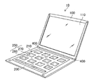
- the electronic device 10 includes a display housing 100 having a display unit 110 for displaying information, and an input housing 200 having a keyboard 210 coupled to the display housing 100. .
- the display housing 100 and the input housing 200 are mechanically coupled to each other by two hinges 400 that are coupling members.
- the display unit 110 and the keyboard 210 are in a position where the user can visually recognize, and the electronic device 10 is in an open state.
- the input housing 200 is installed on the lower side. The user operates the electronic device 10 while visually recognizing the display unit 110 and the keyboard 210.
- Rotating and moving the display housing 100 and the input housing 200 allows the display unit 110 and the keyboard 210 to be covered with each other, and the electronic device 10 is closed.
- the display unit 110 and the keyboard 210 are not visually recognized by the user.
- the electronic device 10 is not used or the electronic device 10 is moved.
- the display housing 100 is rectangular in a plan view and has a thin rectangular parallelepiped shape.
- the shape of the display housing 100 is not particularly limited.
- the display housing 100 may be composed of a plurality of members.
- the display housing 100 is made of, for example, resin.
- the material of the display housing 100 is not limited.
- the display unit 110 is supported by the display housing 100 so as to cover the opening of the display housing 100.
- the display unit 110 displays various types of information (characters, figures, photographs, etc.).
- a liquid crystal display unit is composed of a TFT (Thin Film Transistor) substrate composed of a glass substrate, a resin substrate, etc., a CF (Color Filter) substrate, and a liquid crystal layer sandwiched between the TFT substrate and the CF substrate.
- TFT Thin Film Transistor
- CF Color Filter
- the display unit 110 can include a transparent plate-like member as a protective member on the outer layer side.
- the plate member is made of, for example, resin or glass.
- the input housing 200 is rectangular in plan view and has a thin rectangular parallelepiped shape.
- the shape of the input housing 200 is not particularly limited.
- the input housing 200 may be composed of a plurality of members.
- the input housing 200 is made of, for example, resin. However, the material of the input housing 200 is not limited.
- a signal input via the input housing 200 is input to a control device (not shown) provided in the electronic device 10.
- the control device performs a predetermined process based on the input signal.
- the control device outputs the processing result to the display housing 100.
- the display unit 110 of the display housing 100 displays the display result.
- the keyboard 210 is supported by the input housing 200 so as to cover the opening of the input housing 200.
- the keyboard 210 includes a touch screen and the display unit 110.
- a touch screen (also referred to as a touch panel) detects coordinates touched by a user.
- a capacitive touch screen can be used as the touch screen.
- the capacitive touch screen is configured by, for example, a touch screen substrate and transparent ITO (Indium Tin Oxide) electrodes arranged in a pattern on the touch screen substrate.
- the touch screen is not limited to a capacitance type, and an anti-film type, a surface acoustic wave type, an electromagnetic induction type, or the like can be used.
- the keyboard 210 includes a plate-like member 220 for receiving touch input at the outermost part.
- the plate-like member 220 that receives touch input means a member that a user touches for input.
- the plate-like member 220 is arranged in a region corresponding to a key display portion of the software keyboard, a region corresponding to a portion other than the key display portion, and is different from the key region 230.
- a non-key region 240 made of a material is used.
- the non-key area 240 surrounds the key area 230.
- a user of the electronic device 10 performs an input operation on the electronic device 10 via the key area 230.
- the key area 230 corresponds to the key display portion, and thus generally has a substantially rectangular shape in a top view.
- the shape of the key area 230 is not limited.
- a glass member is used as the material of the key region 230. Since the glass member has a high visible light transmittance, a display unit such as a display may be provided under the key region 230 so that the glass member can be viewed through the glass member. It is preferable because an image for an input key can be displayed on each display, an image corresponding to other software can be displayed, and an image to be displayed in the key area 230 can be changed according to the application.
- the display unit As the display unit, the above-described liquid crystal display unit, organic light emitting diode (organic EL display) unit, or the like can be used.
- a material different from the glass member (hereinafter referred to as a joining member) is used as the material of the non-key region 240.
- characters for input keys may be provided directly on the glass member of the key area 230 by printing or the like. In this case, it is not necessary to provide a display or the like under the glass member.
- the maximum height roughness Rz of the glass member surface is 50 nm or more, and the arithmetic average roughness Ra is 1 nm or more (all are Japanese Industrial Standard 2001). JIS B0601) is preferable. By setting it as such a surface shape, it becomes possible to stop glass member ink. As a result, it is possible to significantly suppress the phenomenon that characters or the like formed with ink unintentionally spread or shift.
- the arithmetic average roughness Ra of the glass member surface (exposed surface) of the key region 230 may be 15 nm or more and 100 nm or less, and an antifouling layer made of a resin containing fluorine may be formed on the exposed surface. By doing so, good finger slipperiness can be realized.
- the film-forming amount X of the antifouling layer represented by the following formula (1) is preferably 0.5 or more and 10 or less, more preferably 2 or more and 8 or less, finger slipping property is improved, which is preferable.
- S1 is the F-K ⁇ ray intensity measured from the antifouling layer side with the fluorescent X-ray measuring device at the position of the glass member surface in the key region 230
- S2 substantially contains fluorine.
- S3 is the F-K ⁇ ray intensity measured with a fluorescent X-ray measuring device for an aluminosilicate glass plate containing 2% by mass of fluorine
- a glass plate substantially free of fluorine means a glass plate having a fluorine content of less than 100 ppm measured by secondary ion mass spectrometry (SIMS), such as a commercially available soda lime glass. But you can.
- SIMS secondary ion mass spectrometry
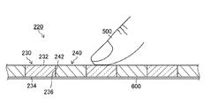
- FIG. 2 is a schematic cross-sectional view of the plate-like member 220 taken along the line II of FIG.
- the glass member of the key region 230 is connected to the opposing main surface 232 and main surface 234, and the main surface 232 and main surface 234, and is a bonding surface with the bonding member of the non-key region 240. And a certain side surface 236.
- the thickness of the key region 230 is preferably, for example, 3 mm or less, more preferably in the range of 0.2 mm to 2.0 mm, and still more preferably in the range of 0.3 mm to 1.5 mm.
- the side surface 236 of the glass member preferably has a concavo-convex structure having an arithmetic average roughness Ra of 2 nm to 100 nm, more preferably 10 nm to 50 nm, and still more preferably 15 nm to 45 nm.
- the concavo-convex structure has a structure in which at least a part of the root part is constricted inward compared to the tip part.
- the constricted structure includes a structure in which the base portion is constricted from both sides to the inside, and a structure in which the base portion is constricted from one side to the inside.
- the side surface 236 of the glass member that is the key region 230 and the end surface 242 of the joining member that is the non-key region 240 are joined. Since the side surface 236 has an uneven structure including a constricted structure, the bonding force between the side surface 236 of the glass member and the end surface 242 of the bonding member can be increased by an anchor effect. Note that the end surface 242 of the bonding member may or may not be roughened. In 1st Embodiment, the case where the side surface 236 and the end surface 242 were joined directly was illustrated. The side surface 236 and the end surface 242 can be joined via an adhesive. Even when an adhesive is used, the bonding force between the side surface 236 and the end surface 242 can be increased by the anchor effect.
- the key region 230 is made of a glass member
- the non-key region 240 is made of a material different from that of the glass member. Therefore, when the plate-like member 220 is touched with the finger 500, the positions of the glass member and the joining member can be recognized by tactile sensation (different from the tactile sensation of the hand). Since the glass member corresponds to the key region 230, if the user can recognize the position of the glass member, the position of the key region 230 can be recognized. Therefore, the user can input to the electronic device 10 by touching a finger like a blind touch.
- the step between the key area 230 and the non-key area 240 is preferably 15 ⁇ m or more and 200 ⁇ m or less.
- the key area 230 and the non-key area 240 can be integrally formed like the plate-like member 220, and the user can more easily feel the step between the key area 230 and the non-key area 240. It is preferable because the key area 230 can be specified.
- the step between the key area 230 and the non-key area 240 is less than 15 ⁇ m, it is substantially flat. Since the position of the key region 230 can be recognized with a simple configuration without providing a projection or the like on the flat plate-like member 220, the electronic device 10 excellent in compatibility between design and key recognition can be obtained.
- the user's key recognition can be further improved.
- a sensor member 600 is provided on the surface opposite to the surface on which the touch input is performed on the plate-like member 220.
- the sensor member 600 can detect touch-input coordinates.
- a mechanism for generating vibration or sound may be provided in combination with the sensor member 600 in order to notify whether or not the area touched by the user is the key area 230. Good.
- Martens hardness of the glass member is preferably less than 2000N / mm 2 or more 4500N / mm 2, more preferably 2000N / mm 2 or more 4000 N / mm 2 or less.
- the durability is good when the Martens hardness is 2000 N / mm 2 or more.
- Martens hardness much more preferably 2000N / mm 2 or more 3500 N / mm 2 or less.
- the Martens hardness is an index representing the softness of the glass surface and can be measured by a method based on ISO14577.
- the glass plate that is the base plate of the glass member is formed by the float method or the fusion method.
- the glass plate is made of soda lime silicate glass, aluminosilicate glass, alkali-free glass, or the like.
- the glass plate may be a chemically tempered glass plate or an unstrengthened glass plate. In the case of a chemically strengthened glass plate, the glass plate contains an alkali metal.
- “chemical strengthening treatment” means that a glass plate is immersed in a molten salt containing an alkali metal, and an alkali metal (ion) having a small atomic diameter existing on the outermost surface of the glass plate is present in the molten salt. This is a general term for technologies that replace alkali metals (ions) with large atomic diameters.
- an alkali metal (ion) having an atomic diameter larger than that of the original atoms before the treatment is arranged on the surface of the treated glass plate. For this reason, a compressive stress layer can be formed on the surface of the glass plate, thereby improving the strength of the glass plate.
- the glass plate contains sodium (Na)
- this sodium is replaced with, for example, potassium (K) in the molten salt (for example, nitrate) during the chemical strengthening treatment.
- the glass substrate contains lithium (Li)
- the lithium is replaced with, for example, sodium (Na) and / or potassium (K) in a molten salt (for example, nitrate). Also good.
- an arithmetic average roughness Ra of 2 nm or more and 100 nm can form an uneven structure on the surface of the side surface 236.
- the surface of the side surface 236 is etched.
- the etching process includes chemical etching and physical etching. In the case of chemical etching, either dry etching or wet etching may be used. In dry etching, for example, a processing gas containing hydrogen fluoride (HF) gas may be used.
- HF hydrogen fluoride
- the temperature of the etching treatment is not particularly limited, but is usually in the range of 400 ° C. or higher and 800 ° C. or lower.
- the temperature of the etching treatment is preferably in the range of 500 ° C. or higher and 700 ° C. or lower, and more preferably in the range of 500 ° C. or higher and 650 ° C. or lower.
- the treatment gas may include a carrier gas and a dilution gas in addition to the hydrogen fluoride gas.
- carrier gas and dilution gas For example, nitrogen and / or argon etc. are used. Moreover, you may add water in process gas.
- the concentration of the hydrogen fluoride gas in the processing gas is not particularly limited as long as the side surface 236 of the glass member is appropriately etched.
- the concentration of the hydrogen fluoride gas in the treatment gas is, for example, in the range of 0.1 vol% or more and 10 vol% or less, preferably in the range of 0.3 vol% or more and 5 vol% or less, and preferably in the range of 0.5 vol% or more and 4 vol%. The following range is more preferable.
- the concentration (vol%) of the hydrogen fluoride gas in the processing gas is obtained from (fluorine gas flow rate / (fluorine gas flow rate + carrier gas flow rate + dilution gas flow rate)) ⁇ 100.
- Glass members Martens hardness is less than 2000N / mm 2 or more 4500N / mm 2, for example, an etching process using hydrogen fluoride, by performing in a temperature range of 400 ° C. or higher 800 ° C. or less, is provided.
- the material of the joining member is not limited as long as it can be joined to the glass member directly or via an adhesive.
- the joining member is preferably a material selected from the group consisting of resins such as epoxy resins and acrylic resins, metals such as silicon and germanium, and wood such as cypress, cedar, zelkova, oak and fir.
- the key area 230 and the non-key area 240 may be colorless and transparent or colored and transparent.
- the key area 230 and the non-key area 240 may have different colors. In the case of different colors, the user can recognize the key area 230 and the non-key area 240 visually.
- the arithmetic average roughness Ra of the glass member surface (exposed surface) at the position corresponding to “F” and “J” is the arithmetic average roughness of the other glass member surfaces.
- the roughness Ra may be changed. By doing so, the user can easily recognize the position of the home position.
- the arithmetic average roughness Ra of the glass member surface (exposed surface) at a position corresponding to “F” and “J” to be less than 15 nm, the user's finger is easily caught only by “F” and “J”. Therefore, it is more preferable.
- the electronic device 10 includes a display casing 100 having a display unit 110 for displaying information, and an input having a keyboard 210 coupled to the display casing 100. Housing 200.
- the display housing 100 and the input housing 200 are mechanically coupled to each other rotatably by two hinges 400 that are coupling members.
- the keyboard 210 includes a plate-like member 250 for receiving touch input at the outermost portion.
- the electronic device 10 of the second embodiment and the electronic device 10 of the first embodiment are different with respect to the configuration of the plate-like member 250.
- the plate-like member 250 is arranged in a non-key region 260 corresponding to a portion other than the keys of the keyboard, and a region corresponding to the key portion, and the non-key region 260. It is comprised from the key area
- the non-key area 260 surrounds the key area 270.
- the second embodiment is different from the first embodiment in that a glass member is used as the non-key region 260 and a bonding member made of a material different from the glass member is used as the key region 270.
- a user of the electronic device 10 performs an input operation on the electronic device 10 via the key area 270.
- the key area 270 corresponds to the key display portion, and therefore generally has a substantially rectangular shape when viewed from above.
- the shape of the key area 270 is not limited.
- the glass member to be the non-key region 260 of the second embodiment has a side surface (not shown) to be joined to the end face (not shown) of the joining member to be the key region 270.
- the side surface has a concavity and convexity structure with an arithmetic average roughness Ra of 2 nm or more and 100 nm or less.
- the bonding force between the side surface of the glass member and the end surface of the bonding member can be increased by an anchor effect.
- the side surface of a glass member and the end surface of a joining member can be joined via an adhesive agent.
- the plate-like member 250 is configured such that the key region 270 is formed of a joining member different from the glass member, and the non-key region 260 is formed of a glass member. Therefore, when the plate-like member 250 is touched with a finger, the positions of the glass member and the joining member can be recognized by a tactile sense (different from the tactile sensation of the hand). Since the joining member corresponds to the key area 270, if the user can recognize the position of the joining member, the position of the key area 270 can be recognized. That is, the user can input to the electronic device 10 by touching a finger like a blind touch.
- the step between the non-key region 260 and the key region 270 is preferably 15 ⁇ m or more and 200 ⁇ m or less.
- the key area 270 and the non-key area 260 can be formed integrally like the plate-like member 250, and the user can more easily feel the difference in level between the key area 270 and the non-key area 260. It is preferable because the key area 270 can be specified.
- the plate member 250 is substantially flat. Since the position of the key can be recognized with a simple configuration without providing a protrusion or the like on the flat plate-like member 250, the electronic device 10 excellent in compatibility between design and key recognition can be obtained.
- 10 electronic device, 100: display housing, 110: display unit, 200: input housing, 210: keyboard, 220: plate member, 230: key area, 232: main surface, 234: main surface, 236 : Side surface, 240: Non-key area, 242: End face, 250: Plate member, 260: Non-key area, 270: Key area, 400: Hinge, 500: Finger, 600: Sensor member
Landscapes
- Engineering & Computer Science (AREA)
- General Engineering & Computer Science (AREA)
- Theoretical Computer Science (AREA)
- Human Computer Interaction (AREA)
- Physics & Mathematics (AREA)
- General Physics & Mathematics (AREA)
- Input From Keyboards Or The Like (AREA)
- Position Input By Displaying (AREA)
Abstract
ハードウェアキーボードの質感を残し、外観に優れたガラスキーボードを備えた電子デバイスを提供することを目的とする。 電子デバイスは、情報を表示するための表示ユニットを有する表示用筐体と、前記表示用筐体と連結され、ソフトウェアキーボードを表示するタッチスクリーン表示ユニットを有する入力用筐体と、を備え、前記キーボードは、使用者からの入力情報を受け付ける複数のキー領域と前記キー領域を取り囲む非キー領域とを有し、前記キー領域および前記非キー領域のいずれか一方はガラス部材であり、もう一方は前記ガラス部材とは異なる材料からなり、前記キー領域と前記非キー領域とが接合されている。
Description
本発明は、ガラスを用いたキーボードを有する電子デバイスに関する。
近年、入力デバイスとしてハードウェアキーボードに代えて、タッチスクリーン表示ユニットにソフトウェアキーボードを表示させる電子デバイスが開発されている。ソフトウェアキーボードをタッチ入力することにより、使用者は電子デバイスに入力操作を行う。
一般的に、電子デバイスのハードウェアキーボードは、特定のキーに突起を設けているので、使用者が触覚によりキーの位置を認識できる。一方、ソフトウェアキーボードでは、タッチスクリーン表示ユニットが平坦であるため突起を設けることができず、使用者がキーの位置を触覚により認識すること困難である。
ソフトウェアキーボードを有する電子デバイスにおいて、使用者がキーの位置を認識することができる技術が提案されている。特許文献1の技術では、タッチスクリーンディスプレイにソフトウェアキーボードを表示し、かつ特定のキーを水平方向および垂直方向から指示するための指示表示を行うための表示制御手段を備える。
上記特許文献1の技術では、画像表示装置に画像として表示されるキーボードを使用者が視覚で認識し、タッチパネルを介して入力を行うソフトウェアキーボードが採用されている。しかし、モバイルPC(Personal Computer)等に代表される入力頻度の高い電子デバイスの入力装置の大半にハードウェアキーボードが採用されている。一方、ブラインドタッチしづらい現状のソフトウェアキーボードは、直感的な入力が難しく、敬遠される傾向にある。
本発明は、上記課題に鑑みてなされたものであって、ハードウェアキーボードの質感を残し、外観に優れたガラスキーボードを備えた電子デバイスを提供することを目的とする。
本発明の電子デバイスは、情報を表示するための表示ユニットを有する表示用筐体と、前記表示用筐体と連結され、キーボードを有する入力用筐体と、を備え、前記キーボードは、使用者からの入力情報を受け付ける複数のキー領域と前記キー領域を取り囲む非キー領域とを有し、前記キー領域および前記非キー領域のいずれか一方はガラス部材であり、もう一方は前記ガラス部材とは異なる材料からなり、前記キー領域と前記非キー領域とが接合されている。
本発明によれば、ハードウェアキーボードの質感を残し、外観に優れたガラスキーボードを備えた電子デバイスを提供できる。
以下、添付図面にしたがって本発明の実施形態について説明する。但し、本発明の範囲を逸脱すること無く、これらの実施形態については種々の変更を行うことができる。なお、添付図中、同一の記号で示される要素は、基本的に、同様の機能を有する同様の要素を表す。
〔第1実施形態〕
第1実施形態の電子デバイスについて、図1は、ラップトップコンピュータ(ノートブックコンピュータとも称される)に代表される電子デバイスの模式的斜視図である。
第1実施形態の電子デバイスについて、図1は、ラップトップコンピュータ(ノートブックコンピュータとも称される)に代表される電子デバイスの模式的斜視図である。
図1に示されるように、電子デバイス10は、情報を表示するための表示ユニット110を有する表示用筐体100と、表示用筐体100と連結されるキーボード210を有する入力用筐体200と、を備える。
図1に示されるように、表示用筐体100と入力用筐体200とは、連結部材である2個のヒンジ400により、回転自在に機械的に連結される。
図1においては、表示ユニット110とキーボード210とを使用者が視認できる位置にあり、電子デバイス10は開いた状態にある。通常は、入力用筐体200が下側に設置される。表示ユニット110とキーボード210を視認しながら、使用者は電子デバイス10を操作する。
表示用筐体100と入力用筐体200とを回転移動させることにより、表示ユニット110とキーボード210とが相互に覆う位置にすることができ、電子デバイス10は閉じた状態となる。閉じた状態では、表示ユニット110とキーボード210とは、使用者に視認されない状態にある。通常、閉じた状態では、電子デバイス10を使用しない場合か、または電子デバイス10を移動させている場合である。
図1に示されるように、表示用筐体100は、平面視において矩形状で、薄い直方体形状を有している。但し、表示用筐体100の形状は、特に限定されない。表示用筐体100は、複数の部材により構成されてもよい。表示用筐体100は、例えば、樹脂等で構成される。しかしながら、表示用筐体100の材料は限定されない。
表示ユニット110は、表示用筐体100の開口部を覆うように、表示用筐体100に支持される。表示ユニット110は各種の情報(文字、図形および写真等)を表示する。表示ユニット110として、液晶表示ユニット、有機発光(有機EL表示)ダイオードユニット等を使用することができる。例えば、液晶表示ユニットは、ガラス基板、樹脂基板等で構成されるTFT(Thin Film Transistor)基板と、CF(Color Filter)基板と、TFT基板およびCF基板に挟持される液晶層と、により構成される。
表示ユニット110は、外層側に保護部材として透明の板状部材を備えることができる。板状部材は、例えば、樹脂、ガラス等により構成される。
図1に示されるように、入力用筐体200は、平面視において矩形状で、薄い直方体形状を有している。入力用筐体200の形状は、特に限定されない。入力用筐体200は、複数の部材により構成されてもよい。入力用筐体200は、例えば、樹脂等で構成される。しかしながら、入力用筐体200の材料は限定されない。
入力用筐体200を介して入力された信号が、電子デバイス10に備えられる制御装置(不図示)に入力される。制御装置は入力信号に基づき、所定の処理を行う。制御装置は処理の結果を表示用筐体100に出力する。表示用筐体100の表示ユニット110は表示結果を表示する。
図1に示されるように、キーボード210は、入力用筐体200の開口部を覆うように、入力用筐体200に支持される。キーボード210は、タッチスクリーンと表示ユニット110とを備える。タッチスクリーン(タッチパネルとも称する)は、使用者がタッチした座標を検出する。タッチスクリーンとして、例えば静電容量式タッチスクリーンを使用することができる。静電容量式タッチスクリーンは、例えば、タッチスクリーン用基板、およびタッチスクリーン用基板にパターン状に配置された透明なITO(Indium Tin Oxide)電極等により構成される。タッチスクリーンは、静電容量式に限定されず、抗膜方式、表面弾性波方式、電磁誘導方式等を使用することができる。
キーボード210は、最表部にタッチ入力を受け付けるための板状部材220を備える。タッチ入力を受け付ける板状部材220とは、入力のために使用者が触れる部材を意味する。
第1実施形態において、板状部材220は、ソフトウェアキーボードのキー表示部分に対応する領域に配置されるキー領域230、およびキー表示部分以外に対応する領域に配置され、かつキー領域230とは異なる材料からなる非キー領域240とから構成される。非キー領域240はキー領域230を取り囲んでいる。電子デバイス10の使用者はキー領域230を介して電子デバイス10に入力操作を実行する。なお、図1に示されるように、キー領域230はキー表示部分に対応するので、一般的には上面視において略矩形状を有している。但し、キー領域230の形状は限定されない。
第1実施形態では、キー領域230の材料にガラス部材を用いている。ガラス部材は可視光透過率が高いため、キー領域230の下にディスプレイ等の表示ユニットを設け、ガラス部材を介して視認可能な構成としても構わない。ディスプレイそれぞれに入力キー用の画像を表示させたり、その他ソフトウェアに対応した画像を表示させたり、用途に応じてキー領域230に表示させる画像を変更できるため好ましい。
上記表示ユニットとしては、上記した液晶表示ユニット、有機発光ダイオード(有機EL表示)ユニット等を使用することができる。
また、第1実施形態では、非キー領域240の材料としてガラス部材とは異なる材料(以下、接合部材と称する。)を用いている。
一方、キー領域230のガラス部材に、直接、印刷等によりで入力キー用の文字等を設けても構わない。この場合はガラス部材の下にディスプレイ等を設けなくて良いため構成が簡便になるため好ましい。ガラス部材に、直接、印刷等により文字等を設ける場合には、ガラス部材表面の最大高さ粗さRzが50nm以上であり、算術平均粗さRaが1nm以上である(いずれも日本工業規格2001 JIS B0601)ことが好ましい。そのような表面形状とすることで、ガラス部材インクを留めることが可能になる。その結果、インクで形成された文字等が不本意に広がったり、ずれたりする現象を有意に抑制することができる。
また、キー領域230のガラス部材表面(露出面)の算術平均粗さRaが15nm以上100nm以下とし、その露出面上にフッ素を含む樹脂からなる防汚層が形成されていても良い。そうすることで良好な指滑り性を実現することが出来る。
特に、下記式(1)で表される防汚層の成膜量Xが、好ましくは0.5以上10以下、より好ましくは2以上8以下の場合、指滑り性が良くなるため好ましい。
X=(S1-S2)/(S3-S2)・・・(1)
式(1)中、S1は、キー領域230のガラス部材表面の位置で、蛍光X線測定装置で防汚層側から測定したF-Kα線強度であり、S2は、フッ素を実質的に含有しないガラス板の蛍光X線測定装置で測定したF-Kα線強度であり、S3は、フッ素を2質量%含有するアルミノシリケー卜ガラス板の蛍光X線測定装置で測定したF-Kα線強度である。
ここで、「フッ素を実質的に含有しないガラス板」とは、二次イオン質量分析法(SIMS)により測定したフッ素の含有量が100ppm未満のガラス板を意味し、たとえば市販のソーダライムガラス等でもよい。
式(1)中、S1は、キー領域230のガラス部材表面の位置で、蛍光X線測定装置で防汚層側から測定したF-Kα線強度であり、S2は、フッ素を実質的に含有しないガラス板の蛍光X線測定装置で測定したF-Kα線強度であり、S3は、フッ素を2質量%含有するアルミノシリケー卜ガラス板の蛍光X線測定装置で測定したF-Kα線強度である。
ここで、「フッ素を実質的に含有しないガラス板」とは、二次イオン質量分析法(SIMS)により測定したフッ素の含有量が100ppm未満のガラス板を意味し、たとえば市販のソーダライムガラス等でもよい。
図2は、図1のI-I線沿う板状部材220の概略断面図である。図2に示されるように、キー領域230のガラス部材は、対向する主面232および主面234、および主面232と主面234とに連なり、非キー領域240の接合部材との接合面である側面236とを有する。キー領域230の厚みは、例えば、3mm以下であることが好ましく、0.2mm以上2.0mm以下の範囲がより好ましく、0.3mm以上1.5mm以下の範囲であることがさらに好ましい。
ガラス部材の側面236は、好ましくは2nm以上100nm以下、より好ましくは、10nm以上50nm以下、さらに好ましくは、15nm以上45nm以下の算術平均粗さRaの凹凸構造を有する。
凹凸構造は、根元部分の少なくとも一部が、先端部分に比べて内方にくびれた構造を有する。くびれた構造には、根元部分が両側から内側にくびれた構造、根元部分が一方側から内側にくびれた構造が含まれる。
図2に示されるように、キー領域230であるガラス部材の側面236と、非キー領域240である接合部材の端面242とが接合される。側面236は、くびれた構造を含む凹凸構造を有するので、アンカー効果によりガラス部材の側面236と、接合部材の端面242との間の接合力を高めることができる。なお、接合部材の端面242は粗面化されていてもよいし、されていなくともよい。
第1実施形態では、側面236と端面242とを直接接合する場合を例示した。側面236と端面242とを接着剤を介して接合することができる。接着剤を使用する場合においても、アンカー効果により、側面236と端面242との接合力を高めることができる。
第1実施形態では、側面236と端面242とを直接接合する場合を例示した。側面236と端面242とを接着剤を介して接合することができる。接着剤を使用する場合においても、アンカー効果により、側面236と端面242との接合力を高めることができる。
第1実施形態では、上述したように、板状部材220はキー領域230がガラス部材で構成され、非キー領域240の領域がガラス部材と異なる材料により構成される。したがって、指500で板状部材220を触れた際、触覚(手の触感に違い)によりガラス部材と接合部材の位置を認識することができる。ガラス部材はキー領域230に対応するので、使用者がガラス部材の位置を認識できれば、キー領域230の位置を認識できる。そのため、使用者は、ブラインドタッチのように指の触覚により、電子デバイス10に入力することが可能となる。
第1実施形態では、キー領域230と非キー領域240の段差は15μm以上200μm以下であることが好ましい。この範囲である場合、キー領域230と非キー領域240が板状部材220のように一体的に形成可能であるとともに、使用者がキー領域230と非キー領域240との段差の触感でより容易にキー領域230を特定できるため好ましい。
また、キー領域230と非キー領域240の段差が15μm未満の場合、実質的に平坦である。平坦な板状部材220に突起等を設けることなく、簡便な構成でキー領域230の位置を認識できるので、意匠性とキー認識性の両立性に優れた電子デバイス10を得ることができる。
さらに、キー領域230の表面と非キー領域240の表面の性状(例えば、算術平均粗さ等)を異ならせることにより、さらに、使用者のキー認識性を向上させることができる。
なお、図2に示されるように、板状部材220のタッチ入力される面と反対面にはセンサ部材600が設けられる。センサ部材600により、タッチ入力された座標を検出することができる。さらに、キー領域230がタッチされた場合に、使用者に触れている領域がキー領域230であるか否かを知らせるために、振動や音を発生させる機構をセンサ部材600に併せて設けてもよい。
次に、ガラス部材の好ましい態様について説明する。
ガラス部材のマルテンス硬さは、2000N/mm2以上4500N/mm2未満が好ましく、2000N/mm2以上4000N/mm2以下であることがより好ましい。マルテンス硬さが2000N/mm2以上の場合、耐久性がよい。また、マルテンス硬さが4500N/mm2未満であれば、切断等の加工が可能であり、4000N/mm2以下の場合、指で触ったときに適度なへこみ感が得られる。マルテンス硬さは、さらに好ましくは2000N/mm2以上3500N/mm2以下である。なお、マルテンス硬さは、ガラスの表面の柔らかさを表す指標であり、ISO14577に準拠した方法で測定可能である。
ガラス部材のマルテンス硬さは、2000N/mm2以上4500N/mm2未満が好ましく、2000N/mm2以上4000N/mm2以下であることがより好ましい。マルテンス硬さが2000N/mm2以上の場合、耐久性がよい。また、マルテンス硬さが4500N/mm2未満であれば、切断等の加工が可能であり、4000N/mm2以下の場合、指で触ったときに適度なへこみ感が得られる。マルテンス硬さは、さらに好ましくは2000N/mm2以上3500N/mm2以下である。なお、マルテンス硬さは、ガラスの表面の柔らかさを表す指標であり、ISO14577に準拠した方法で測定可能である。
ガラス部材の素板となるガラス板は、フロート法、またはフュージョン法などで成形される。ガラス板は、ソーダライムシリケートガラス、アルミノシリケートガラス、または無アルカリガラスなどで構成される。ガラス板は、化学強化処理がなされたガラス板でも、未強化のガラス板でもよい。化学強化ガラス板の場合、ガラス板はアルカリ金属を含む。
ここで、「化学強化処理」とは、アルカリ金属を含む溶融塩中にガラス板を浸漬させ、ガラス板の最表面に存在する原子径の小さなアルカリ金属(イオン)を、溶融塩中に存在する原子径の大きなアルカリ金属(イオン)と置換する技術の総称を言う。「化学強化処理」では、処理されたガラス板の表面には、処理前の元の原子よりも原子径の大きなアルカリ金属(イオン)が配置される。このため、ガラス板の表面に圧縮応力層を形成することができ、これによりガラス板の強度が向上する。
例えば、ガラス板がナトリウム(Na)を含む場合、化学強化処理の際、このナトリウムは、溶融塩(例えば硝酸塩)中で、例えばカリウム(K)と置換される。あるいは、例えば、ガラス基板がリチウム(Li)を含む場合、化学強化処理の際、このリチウムは、溶融塩(例えば硝酸塩)中で、例えばナトリウム(Na)および/またはカリウム(K)と置換されてもよい。
ガラス部材の側面236を粗面化処理することにより、側面236の表面に2nm以上100nmの算術平均粗さRaが凹凸構造を形成できる。例えば、粗面化処理では、側面236の表面にエッチング処理が行われる。エッチング処理には、化学エッチング、物理エッチング等が含まれる。化学エッチングの場合は、ドライエッチング、ウェットエッチングのいずれでもよい。ドライエッチングでは、例えばフッ化水素(HF)ガスを含む処理ガスを用いてもよい。
エッチング処理の温度は、特に限られないが、通常、400℃以上800℃以下の範囲である。エッチング処理の温度は、500℃以上700℃以下の範囲であることが好ましく、500℃以上650℃以下の範囲であることがより好ましい。
処理ガスは、フッ化水素ガスの他、キャリアガスおよび希釈ガスを含んでもよい。キャリアガス、希釈ガスとしては、特に限定されないが、例えば、窒素および/またはアルゴン等が使用される。また、処理ガス中に水を加えても構わない。
処理ガス中のフッ化水素ガスの濃度は、ガラス部材の側面236が適正にエッチング処理される限り、特に限定されない。処理ガス中のフッ化水素ガスの濃度は、例えば、0.1vol%以上10vol%以下の範囲であり、0.3vol%以上5vol%以下の範囲であることが好ましく、0.5vol%以上4vol%以下の範囲であることがより好ましい。このとき、処理ガス中のフッ化水素ガスの濃度(vol%)は、(フッ素ガス流量/(フッ素ガス流量+キャリアガス流量+希釈ガス流量))×100より求められる。
マルテンス硬さが2000N/mm2以上4500N/mm2未満であるガラス部材は、例えば、フッ化水素を用いたエッチング処理を、400℃以上800℃以下の温度範囲で行うことにより、提供される。
マルテンス硬さが2000N/mm2以上4500N/mm2未満であるガラス部材は、例えば、フッ化水素を用いたエッチング処理を、400℃以上800℃以下の温度範囲で行うことにより、提供される。
次に接合部材について説明する。接合部材はガラス部材と直接または接着剤を介して接合することができる限り、材料は限定されない。例えば、接合部材はエポキシ樹脂、アクリル樹脂などの樹脂、シリコン、ゲルマニウムなどの金属およびヒノキ、スギ、ケヤキ、カシ、モミなどの木材からなる群から選択される材料であることが好ましい。
図1において、キー領域230と非キー領域240とは無色透明であっても、また着色透明であってもよい。キー領域230と非キー領域240とを異なる色としてもよい。異なる色とした場合、さらに視覚により、使用者はキー領域230と非キー領域240とを認識できる。
第1実施形態のキー領域230がQWERTYキーボードの場合、「F」と「J」に対応する位置のガラス部材表面(露出面)の算術平均粗さRaを、それ以外のガラス部材表面の算術平均粗さRaと変化させてもよい。そうすることで、使用者が容易にホームポジションの位置を認識することが出来る。特に、「F」と「J」に対応する位置のガラス部材表面(露出面)の算術平均粗さRaを15nm未満とすることで、使用者の指が「F」と「J」のみ引っ掛かり易くなるためより好ましい。
〔第2実施形態〕
第2実施形態の電子デバイスを、図3を参照して説明する。なお、第1実施形態の電子デバイスと同様の構成には同一符号を付したが、その説明を省略する場合がある。
第2実施形態の電子デバイスを、図3を参照して説明する。なお、第1実施形態の電子デバイスと同様の構成には同一符号を付したが、その説明を省略する場合がある。
図3に示されるように、第2実施形態の電子デバイス10は、情報を表示するための表示ユニット110を有する表示用筐体100と、表示用筐体100と連結されるキーボード210を有する入力用筐体200と、を備える。
図3に示されるように、表示用筐体100と入力用筐体200とは、連結部材である2個のヒンジ400により、回転自在に機械的に連結される。
キーボード210は、最表部にタッチ入力を受け付けるための板状部材250を備える。
キーボード210は、最表部にタッチ入力を受け付けるための板状部材250を備える。
第2実施形態の電子デバイス10と第1実施形態の電子デバイス10とは、板状部材250の構成に関して異なる。
図3に示されるように、第2実施形態において、板状部材250は、キーボードのキー以外の部分に対応する非キー領域260、およびキー部分に対応する領域に配置され、かつ非キー領域260とは異なる材料からなるキー領域270から構成される。非キー領域260はキー領域270を取り囲んでいる。第2実施形態では、非キー領域260としてガラス部材を、キー領域270としてガラス部材とは異なる材料である接合部材を用いている点が、第1実施形態とは異なる。電子デバイス10の使用者は、キー領域270を介して電子デバイス10への入力操作を実行する。なお、図3に示されるように、キー領域270はキー表示部分に対応するので、一般的には上面視において略矩形状を有している。但し、キー領域270の形状は限定されない。
図3に示されるように、第2実施形態において、板状部材250は、キーボードのキー以外の部分に対応する非キー領域260、およびキー部分に対応する領域に配置され、かつ非キー領域260とは異なる材料からなるキー領域270から構成される。非キー領域260はキー領域270を取り囲んでいる。第2実施形態では、非キー領域260としてガラス部材を、キー領域270としてガラス部材とは異なる材料である接合部材を用いている点が、第1実施形態とは異なる。電子デバイス10の使用者は、キー領域270を介して電子デバイス10への入力操作を実行する。なお、図3に示されるように、キー領域270はキー表示部分に対応するので、一般的には上面視において略矩形状を有している。但し、キー領域270の形状は限定されない。
第1実施形態と同様、第2実施形態の非キー領域260となるガラス部材は、キー領域270となる接合部材の端面(不図示)と接合される側面(不図示)を有し、ガラス部材の側面は、2nm以上100nm以下の算術平均粗さRaのくびれた凹凸構造を有する。
ガラス部材の側面は、くびれた構造を含む凹凸構造を有するので、アンカー効果によりガラス部材の側面と接合部材の端面との間の接合力を高めることができる。第2実施形態では、側面236と端面242とを直接接合する場合を例示したが、ガラス部材の側面と接合部材の端面とを接着剤を介して接合することができる。
第2実施形態では、板状部材250は、キー領域270がガラス部材と異なる接合部材で構成され、非キー領域260がガラス部材により構成される。したがって、指で板状部材250を触れた際、触覚(手の触感に違い)によりガラス部材と接合部材の位置を認識することができる。接合部材はキー領域270に対応するので、使用者が接合部材の位置を認識できれば、キー領域270の位置を認識できる。すなわち、使用者は、ブラインドタッチのように指の触覚により、電子デバイス10に入力することが可能となる。
第2実施形態において、非キー領域260とキー領域270の段差は15μm以上200μm以下であることが好ましい。この範囲である場合、キー領域270と非キー領域260が板状部材250のように一体的に形成可能であるとともに、使用者がキー領域270と非キー領域260との段差の触感でより容易にキー領域270を特定できるため好ましい。
また、キー領域270と非キー領域260の段差が15μm未満の場合、板状部材250は、実質的に平坦である。平坦な板状部材250に突起等を設けることなく、簡便な構成でキーの位置を認識できるので、意匠性とキー認識性の両立性に優れた電子デバイス10を得ることができる。
なお、2017年4月19日に出願された日本特許出願2017-082699号の明細書、特許請求の範囲、図面、及び要約書の全内容をここに引用し、本発明の明細書の開示として、取り入れるものである。
10:電子デバイス、 100:表示用筐体、 110:表示ユニット、 200:入力用筐体、 210:キーボード、 220:板状部材、 230:キー領域、 232:主面、 234:主面、 236:側面、 240:非キー領域、 242:端面、 250:板状部材、 260:非キー領域、 270:キー領域、 400:ヒンジ、 500:指、 600:センサ部材
Claims (16)
- 情報を表示するための表示ユニットを有する表示用筐体と、
前記表示用筐体と連結され、キーボードを有する入力用筐体と、を備え、
前記キーボードは、使用者からの入力情報を受け付ける複数のキー領域と前記キー領域を取り囲む非キー領域とを有し、
前記キー領域および前記非キー領域のいずれか一方はガラス部材であり、もう一方は前記ガラス部材とは異なる材料からなり、
前記キー領域と前記非キー領域とが接合されている電子デバイス。 - 前記キー領域がガラス部材であり、前記非キー領域との接合面の算術平均粗さRaが2nm以上100nm以下である請求項1に記載の電子デバイス。
- 前記非キー領域がガラス部材であり、前記キー領域との接合面の算術平均粗さRaが2nm以上100nm以下である請求項1に記載の電子デバイス。
- 前記ガラス部材の接合面の算術平均粗さRaが、10nm以上50nm以下である請求項1又は2に記載の電子デバイス。
- 前記ガラス部材の接合面の算術平均粗さRaが、15nm以上45nm以下である請求項1又は2に記載の電子デバイス。
- 前記ガラス部材の接合面が、エッチングにより粗面化処理されている請求項1から5の何れか一項に記載の電子デバイス。
- 前記ガラス部材のマルテンス硬さが、2000N/mm2以上4500N/mm2未満である請求項1から6の何れか一項に記載の電子デバイス。
- 前記キー領域と前記非キー領域との段差が15μm未満である請求項1から7の何れか一項に記載の電子デバイス。
- 前記キー領域と前記非キー領域との段差が15μm以上200μm以下である請求項1から7の何れか一項に記載の電子デバイス。
- 前記ガラス部材の露出面の最大高さRzが50nm以上であり、算術平均粗さRaが1nm以上である、請求項1から9の何れか一項に記載の電子デバイス。
- 前記ガラス部材の露出面の算術平均粗さRaが15nm以上100nm以下であり、その露出面上にフッ素を含む樹脂からなる防汚層が設けられている請求項1から10の何れか一項に記載の電子デバイス。
- 前記防汚層の下記式(1)で表される成膜量Xが、0.5以上10以下である請求項11に記載の電子デバイス。
X=(S1-S2)/(S3-S2)・・・(1)
(S1は、キー領域230のガラス部材表面の位置で、蛍光X線測定装置で防汚層側から測定したF-Kα線強度である。S2は、フッ素を実質的に含有しないガラス板の蛍光X線測定装置で測定したF-Kα線強度である。S3は、フッ素を2質量wt%含有するアルミノシリケー卜ガラス板の蛍光X線測定装置で測定したF-Kα線強度である。 - 前記異なる材料が、樹脂、金属および木材からなる群から選択される材料である請求項1から12の何れか一項に記載の電子デバイス。
- 前記キー領域と前記非キー領域とが接着剤を介して接合される請求項1から13の何れか一項に記載の電子デバイス。
- 前記ガラス部材が化学強化ガラスで構成される請求項1から14の何れか一項に記載の電子デバイス。
- 前記キーボードはQWERTYキーボードであり、「F」と「J」に対応する位置の前記ガラス部材の露出面の算術平均粗さRaが、それ以外のガラス部材の露出面の算術平均粗さRaと異なっており、かつ15nm未満である請求項2に記載の電子デバイス。
Applications Claiming Priority (2)
| Application Number | Priority Date | Filing Date | Title |
|---|---|---|---|
| JP2017082699A JP2020106871A (ja) | 2017-04-19 | 2017-04-19 | 電子デバイス |
| JP2017-082699 | 2017-04-19 |
Publications (1)
| Publication Number | Publication Date |
|---|---|
| WO2018194098A1 true WO2018194098A1 (ja) | 2018-10-25 |
Family
ID=63856135
Family Applications (1)
| Application Number | Title | Priority Date | Filing Date |
|---|---|---|---|
| PCT/JP2018/016017 Ceased WO2018194098A1 (ja) | 2017-04-19 | 2018-04-18 | 電子デバイス |
Country Status (2)
| Country | Link |
|---|---|
| JP (1) | JP2020106871A (ja) |
| WO (1) | WO2018194098A1 (ja) |
Cited By (1)
| Publication number | Priority date | Publication date | Assignee | Title |
|---|---|---|---|---|
| JP2020167085A (ja) * | 2019-03-29 | 2020-10-08 | 大日本印刷株式会社 | 光学フィルムおよび画像表示装置 |
Citations (6)
| Publication number | Priority date | Publication date | Assignee | Title |
|---|---|---|---|---|
| JP2012027523A (ja) * | 2010-07-20 | 2012-02-09 | Kddi Corp | 携帯電話用のキーボード |
| JP2012141872A (ja) * | 2011-01-05 | 2012-07-26 | Sony Corp | 電子機器及び入力装置 |
| WO2012098823A1 (ja) * | 2011-01-21 | 2012-07-26 | 日本電気株式会社 | スイッチおよび入力装置 |
| JP2013050903A (ja) * | 2011-08-31 | 2013-03-14 | Fujitsu Component Ltd | 平面入力キーボード |
| JP2014201452A (ja) * | 2013-04-01 | 2014-10-27 | 日本電気硝子株式会社 | ガラス−セラミック接合体 |
| WO2016080432A1 (ja) * | 2014-11-20 | 2016-05-26 | 旭硝子株式会社 | 透明板、タッチパッド、およびタッチパネル |
-
2017
- 2017-04-19 JP JP2017082699A patent/JP2020106871A/ja active Pending
-
2018
- 2018-04-18 WO PCT/JP2018/016017 patent/WO2018194098A1/ja not_active Ceased
Patent Citations (6)
| Publication number | Priority date | Publication date | Assignee | Title |
|---|---|---|---|---|
| JP2012027523A (ja) * | 2010-07-20 | 2012-02-09 | Kddi Corp | 携帯電話用のキーボード |
| JP2012141872A (ja) * | 2011-01-05 | 2012-07-26 | Sony Corp | 電子機器及び入力装置 |
| WO2012098823A1 (ja) * | 2011-01-21 | 2012-07-26 | 日本電気株式会社 | スイッチおよび入力装置 |
| JP2013050903A (ja) * | 2011-08-31 | 2013-03-14 | Fujitsu Component Ltd | 平面入力キーボード |
| JP2014201452A (ja) * | 2013-04-01 | 2014-10-27 | 日本電気硝子株式会社 | ガラス−セラミック接合体 |
| WO2016080432A1 (ja) * | 2014-11-20 | 2016-05-26 | 旭硝子株式会社 | 透明板、タッチパッド、およびタッチパネル |
Cited By (1)
| Publication number | Priority date | Publication date | Assignee | Title |
|---|---|---|---|---|
| JP2020167085A (ja) * | 2019-03-29 | 2020-10-08 | 大日本印刷株式会社 | 光学フィルムおよび画像表示装置 |
Also Published As
| Publication number | Publication date |
|---|---|
| JP2020106871A (ja) | 2020-07-09 |
Similar Documents
| Publication | Publication Date | Title |
|---|---|---|
| US10871828B2 (en) | Device having integrated interface system | |
| KR100991802B1 (ko) | 터치 제어 구조를 가진 디스플레이 패널 | |
| JP6185462B2 (ja) | タッチパネル及びその製造方法 | |
| JP5406320B2 (ja) | タッチパネル | |
| JP2014069572A (ja) | 透明導電性基材及びこれを含むタッチパネル | |
| CN201218888Y (zh) | 整合触控结构的显示面板 | |
| US20180288887A1 (en) | Electronic device | |
| KR100894310B1 (ko) | 강화유리를 이용한 터치패널 | |
| US20140078074A1 (en) | Touch panel | |
| JP2014093070A (ja) | タッチパネル及びその製造方法 | |
| JP2014049115A (ja) | タッチパネル及びその製造方法 | |
| US20140078111A1 (en) | Touch panel | |
| KR20140000076A (ko) | 터치패널 | |
| US20130269991A1 (en) | Touch panel | |
| JP6755025B2 (ja) | カバーガラスおよびタッチパネル装置 | |
| WO2018194098A1 (ja) | 電子デバイス | |
| KR100893499B1 (ko) | 터치패널 | |
| US20140078098A1 (en) | Touch panel | |
| JP2018010394A (ja) | 入力装置 | |
| US20140160370A1 (en) | Transparent Conductive Substrate And Touch Panel Including The Same | |
| JP2014056557A (ja) | タッチパネル | |
| KR200466035Y1 (ko) | 터치 패널 보호용 커버 | |
| JP2012248010A (ja) | 入力装置、表示装置、および機器 | |
| KR101755527B1 (ko) | 투명 도전성 기재, 이의 제조방법, 및 이를 구비한 터치 패널 | |
| JP2011017795A (ja) | 光学フィルム構造 |
Legal Events
| Date | Code | Title | Description |
|---|---|---|---|
| 121 | Ep: the epo has been informed by wipo that ep was designated in this application |
Ref document number: 18788548 Country of ref document: EP Kind code of ref document: A1 |
|
| NENP | Non-entry into the national phase |
Ref country code: DE |
|
| 122 | Ep: pct application non-entry in european phase |
Ref document number: 18788548 Country of ref document: EP Kind code of ref document: A1 |
|
| NENP | Non-entry into the national phase |
Ref country code: JP |