WO2018190255A1 - モータモデルシミュレーションプログラム、モータシミュレータ、車両統合シミュレータ - Google Patents
モータモデルシミュレーションプログラム、モータシミュレータ、車両統合シミュレータ Download PDFInfo
- Publication number
- WO2018190255A1 WO2018190255A1 PCT/JP2018/014677 JP2018014677W WO2018190255A1 WO 2018190255 A1 WO2018190255 A1 WO 2018190255A1 JP 2018014677 W JP2018014677 W JP 2018014677W WO 2018190255 A1 WO2018190255 A1 WO 2018190255A1
- Authority
- WO
- WIPO (PCT)
- Prior art keywords
- motor
- unit
- value
- operating point
- model
- Prior art date
- Legal status (The legal status is an assumption and is not a legal conclusion. Google has not performed a legal analysis and makes no representation as to the accuracy of the status listed.)
- Ceased
Links
Images


Classifications
-
- B—PERFORMING OPERATIONS; TRANSPORTING
- B60—VEHICLES IN GENERAL
- B60L—PROPULSION OF ELECTRICALLY-PROPELLED VEHICLES; SUPPLYING ELECTRIC POWER FOR AUXILIARY EQUIPMENT OF ELECTRICALLY-PROPELLED VEHICLES; ELECTRODYNAMIC BRAKE SYSTEMS FOR VEHICLES IN GENERAL; MAGNETIC SUSPENSION OR LEVITATION FOR VEHICLES; MONITORING OPERATING VARIABLES OF ELECTRICALLY-PROPELLED VEHICLES; ELECTRIC SAFETY DEVICES FOR ELECTRICALLY-PROPELLED VEHICLES
- B60L9/00—Electric propulsion with power supply external to the vehicle
- B60L9/16—Electric propulsion with power supply external to the vehicle using AC induction motors
- B60L9/18—Electric propulsion with power supply external to the vehicle using AC induction motors fed from DC supply lines
-
- G—PHYSICS
- G06—COMPUTING OR CALCULATING; COUNTING
- G06F—ELECTRIC DIGITAL DATA PROCESSING
- G06F30/00—Computer-aided design [CAD]
-
- G—PHYSICS
- G06—COMPUTING OR CALCULATING; COUNTING
- G06Q—INFORMATION AND COMMUNICATION TECHNOLOGY [ICT] SPECIALLY ADAPTED FOR ADMINISTRATIVE, COMMERCIAL, FINANCIAL, MANAGERIAL OR SUPERVISORY PURPOSES; SYSTEMS OR METHODS SPECIALLY ADAPTED FOR ADMINISTRATIVE, COMMERCIAL, FINANCIAL, MANAGERIAL OR SUPERVISORY PURPOSES, NOT OTHERWISE PROVIDED FOR
- G06Q50/00—Information and communication technology [ICT] specially adapted for implementation of business processes of specific business sectors, e.g. utilities or tourism
- G06Q50/04—Manufacturing
-
- H—ELECTRICITY
- H02—GENERATION; CONVERSION OR DISTRIBUTION OF ELECTRIC POWER
- H02P—CONTROL OR REGULATION OF ELECTRIC MOTORS, ELECTRIC GENERATORS OR DYNAMO-ELECTRIC CONVERTERS; CONTROLLING TRANSFORMERS, REACTORS OR CHOKE COILS
- H02P29/00—Arrangements for regulating or controlling electric motors, appropriate for both AC and DC motors
-
- Y—GENERAL TAGGING OF NEW TECHNOLOGICAL DEVELOPMENTS; GENERAL TAGGING OF CROSS-SECTIONAL TECHNOLOGIES SPANNING OVER SEVERAL SECTIONS OF THE IPC; TECHNICAL SUBJECTS COVERED BY FORMER USPC CROSS-REFERENCE ART COLLECTIONS [XRACs] AND DIGESTS
- Y02—TECHNOLOGIES OR APPLICATIONS FOR MITIGATION OR ADAPTATION AGAINST CLIMATE CHANGE
- Y02P—CLIMATE CHANGE MITIGATION TECHNOLOGIES IN THE PRODUCTION OR PROCESSING OF GOODS
- Y02P90/00—Enabling technologies with a potential contribution to greenhouse gas [GHG] emissions mitigation
- Y02P90/30—Computing systems specially adapted for manufacturing
-
- Y—GENERAL TAGGING OF NEW TECHNOLOGICAL DEVELOPMENTS; GENERAL TAGGING OF CROSS-SECTIONAL TECHNOLOGIES SPANNING OVER SEVERAL SECTIONS OF THE IPC; TECHNICAL SUBJECTS COVERED BY FORMER USPC CROSS-REFERENCE ART COLLECTIONS [XRACs] AND DIGESTS
- Y02—TECHNOLOGIES OR APPLICATIONS FOR MITIGATION OR ADAPTATION AGAINST CLIMATE CHANGE
- Y02T—CLIMATE CHANGE MITIGATION TECHNOLOGIES RELATED TO TRANSPORTATION
- Y02T10/00—Road transport of goods or passengers
- Y02T10/60—Other road transportation technologies with climate change mitigation effect
- Y02T10/72—Electric energy management in electromobility
Definitions
- the present invention relates to a motor model simulation program, a motor simulator, and a vehicle integration simulator.
- the vehicle system is a complex system consisting of a combination of many parts.
- functions required for vehicles have become increasingly sophisticated and complex, such as fuel efficiency reduction and safety performance enhancement.
- market requirements change year by year, it is necessary to shorten the development period and respond to customer needs as soon as possible.
- a vehicle integration simulator is being promoted as a technique for realizing the above-mentioned problems.
- the purpose of this is to formulate or program the vehicle so that the behavior of the entire vehicle can be simulated using a computer or the like, and to estimate the performance of the vehicle by calculation regardless of the actual vehicle.
- formulas and programs are referred to as “models”, and making a state in which simulation is possible using a model is referred to as “modeling”.
- the vehicle integrated simulator it is possible to perform performance evaluation on a computer, where performance evaluation has been performed by prototyping a vehicle. As a result, more design proposals can be evaluated than prototypes, and a design more suitable for customer requirements can be selected. In addition, the cost of trial production can be reduced except for parts that cannot be evaluated without trial production, so the development cost can be reduced. Furthermore, since the time required for evaluation is generally shorter for the vehicle integrated simulator than for the prototype, a reduction in the development period can be expected.
- the vehicle integrated simulator is usually realized by using a control system CAD such as MATLAB (registered trademark) or Simulink (registered trademark).
- a control system CAD such as MATLAB (registered trademark) or Simulink (registered trademark).
- MATLAB registered trademark
- Simulink registered trademark
- a block refers to a group of models that compute output from input and internal states.
- the size of the block (hereinafter referred to as “granularity”) can be freely set, but in general, one part constituting the vehicle is often set as one block. In this case, the difference in component characteristics is realized by changing the parameter value of each block. If a block is created for each part, when the part is actually replaced, the vehicle integration simulator can cope with the replacement of the corresponding part of the block, thereby reducing the number of man-hours required for the change.
- each part maker can design each block in parallel, which has the advantage of shortening the development period.
- the vehicle integrated simulator has been mainly used for applications such as fuel efficiency evaluation and driving performance evaluation.
- an attempt has been made to calculate vehicle characteristics when parts having various characteristics are applied, and to compare the calculation results to select the most suitable parts for the vehicle. It has been broken.
- the selection of a motor is directly related to the vehicle performance, and therefore the importance of selecting a motor is increasing.
- Patent Document 1 discloses a simulation method of an advance value that can obtain an optimum advance value in a three-dimensional magnetic field analysis for obtaining the efficiency of a motor on a computer.
- a motor model simulation program is executable by a computer, and the computer outputs an operating point sweep that outputs an operating point inside a motor operating area based on an output request value relating to a motor mounted on a vehicle.
- a parameter setting unit for setting a structural parameter related to the structure of the motor, a motor input generating unit for generating an input value to a motor model that models the motor based on the operating point, and the structural parameter Based on the electrical parameters related to the electrical characteristics of the motor set based on the motor calculation unit that calculates the output value for the input value using the motor model, so that the output value approaches the output required value, It functions as a correction unit that changes the structural parameter.
- a motor simulator includes an operating point sweep unit that outputs an operating point inside a motor operating region based on an output request value related to a motor mounted on a vehicle, and a parameter setting unit that sets a structural parameter related to the structure of the motor.
- a motor input creation unit that creates an input value to a motor model obtained by modeling the motor based on the operating point, and an electrical parameter related to electrical characteristics of the motor set based on the structural parameter.
- a motor calculation unit that calculates an output value with respect to the input value using the motor model, and a correction unit that changes the structural parameter so that the output value approaches the output request value.
- a vehicle integrated simulator includes a motor model generation unit that generates a motor model that models a motor mounted on a vehicle, and a plurality of blocks that respectively model components that constitute the vehicle.
- An overall vehicle model including at least the motor model, and the motor model generation unit outputs an operation point within the motor operation region based on an output request value related to the motor,
- a parameter setting unit for setting a structural parameter related to the structure;
- a motor input generating unit for generating an input value to the motor model based on the operating point; and an electrical characteristic of the motor set based on the structural parameter
- the output value for the input value is calculated using the motor model.
- a motor calculation unit for, such that the output value approaches the required output value, and a correction unit configured to change the structural parameters.
- the vehicle integrated simulator according to the present invention simulates the actual driving conditions of an electric vehicle such as an electric vehicle or a hybrid vehicle that can be driven by an electric motor, and obtains the behavior of each part of the vehicle at that time by simulation. It is. Use of such a vehicle integrated simulator is suitable for selecting parts that satisfy the required characteristics.
- a three-phase AC motor is often used for an electric vehicle motor, and an inverter is used for driving control thereof. Therefore, the performance of the motor depends on the operation of the inverter.
- the vehicle integrated simulator according to the present invention comprehensively determines the electric parameters of the motor in consideration of the operation of the inverter. This contributes to improved usability and labor saving when the vehicle designer uses this simulator.
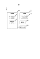
- FIG. 1 is a diagram showing a hardware configuration of a vehicle integration simulator according to an embodiment of the present invention.
- the vehicle integrated simulator 1 shown in FIG. 1 includes a control unit 501, a storage unit 502, a display unit 503, and an operation input unit 504.
- the control unit 501 is a computer configured with, for example, a CPU, a ROM, a RAM, and the like.
- the control unit 501 functions as the entire vehicle model 2 and the motor model generation unit 3 by executing a simulation program (not shown) stored in the storage unit 502. Details of the overall vehicle model 2 and the motor model generation unit 3 will be described later with reference to FIG.
- the storage unit 502 is a non-volatile storage device configured by, for example, a hard disk drive (HDD), a solid state drive (SSD), or the like.
- the storage unit 502 stores a plant model entity database 40 used by the vehicle overall model 2 and the motor model generation unit 3. Details of the plant model entity database 40 will be described later with reference to FIG.
- the display unit 503 is configured by, for example, a liquid crystal display or the like, and displays a simulation result performed by the overall vehicle model 2 or the motor model generation unit 3 and presents it to a user such as a vehicle designer.
- the operation input unit 504 includes, for example, a keyboard and a mouse, and detects an operation input from the user and notifies the control unit 501 of the operation input.
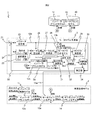
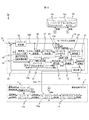
- FIG. 2 is a diagram showing a software configuration of the vehicle integration simulator according to the first embodiment of the present invention.
- the vehicle integrated simulator 1 of this embodiment includes a vehicle overall model 2, a motor model generation unit 3, and a plant model entity database 40 as functions in software configuration.
- the vehicle overall model 2 has an inverter control model 11, an inverter plant model 12a, a motor plant model 13a, and a gear box plant model 14 each of which models the parts constituting the simulation target vehicle. These models derive the behavior of each component of the inverter controller, inverter, motor, and gear box.
- the block (calculation) in the control system 1D CAD such as MATLAB (registered trademark) and Simulink (registered trademark) It is expressed as a group of However, it may be a computer program realized by another model expression format, for example, a mathematical formula, a table (map) format, C language, or the like. Note that the entire vehicle model 2 is actually very complex with many components, and for simplification of description, FIG. 2 shows only the portion related to the motor model generation unit 3 extracted. ing.
- the inverter control model 11 is a block that creates an inverter control signal with the required torque and the required rotational speed of the inverter as inputs.
- the inverter plant model 12a is input with the inverter control signal created by the inverter control model 11, the DC voltage supplied from the battery to the inverter, and the AC current output from the inverter to the motor. This is a block for calculating the AC voltage applied to the motor.
- the motor plant model 13a is a block that calculates motor torque and AC current from the AC voltage applied to the motor and the motor speed.
- the gearbox plant model 14 is a block that calculates the output torque of the axle using the output torque of the motor.
- the inverter plant model 12a and the motor plant model 13a are respectively indicated by broken lines.
- the inverter plant model 12a is configured to refer to the inverter plant model 12 and the motor plant model 13 stored in the plant model entity database 40 via the tag B, and the motor plant model 13a is referred to via the tag A.
- These plant models stored in the plant model entity database 40 represent the entity of each plant model obtained by modeling the inverter and the motor, respectively. That is, the same contents as the inverter plant model 12 and the motor plant model 13 stored in the plant model entity database 40 are reflected in the entire vehicle model 2 as the inverter plant model 12a and the motor plant model 13a.
- the motor model generation unit 3 includes a parameter setting unit 23, an operating point sweep unit 24, an overmodulation rate sweep unit 25, a motor current setting unit 26, a motor input creation unit 27, a motor calculation unit 28, a torque ripple calculation unit 29, and an inverter loss calculation. Section 30, total efficiency calculation section 31, trade-off evaluation section 32, evaluation result storage section 33, and correction section 34.
- An output request value 21 determined by the user is input to the motor model generation unit 3.
- the required output value 21 is a required motor design value related to vehicle characteristics, such as the motor size, target torque, and maximum rotational speed.
- the required output value 21 input to the motor model generation unit 3 is corrected by being added to the correction value 22 from the correction unit 34 and input to the parameter setting unit 23, the operating point sweep unit 24, and the inverter loss calculation unit 30. Is done.
- the parameter setting unit 23 sets a motor parameter representing a physical quantity or set value related to the behavior of the motor based on the input output request value 21 after correction, that is, the addition value of the output request value 21 and the correction value 22. To do.
- motor parameters are classified into three types, “structural parameters”, “electrical parameters”, and “control parameters”, according to their characteristics.
- the structural parameters are parameters related to the shape and structure of the motor, such as the shaft length and inner diameter of the motor and the thickness of the magnet.
- the electrical parameter is a parameter related to the electrical characteristics of the motor, such as battery voltage, d-axis inductance, q-axis inductance, winding resistance, and the like, which is directly used for calculation when simulating the behavior of the motor. Electrical parameters include those determined by structural parameters.
- the control parameter is a parameter related to a motor control condition mainly used for creating an input to the motor calculation unit 28, and corresponds to conditions such as a q-axis current, a d-axis current, and a DC voltage.
- adjustment parameters for convergence calculation of electrical parameters such as weights of evaluation functions and learning coefficients, which will be described later, are also included in the control parameters.
- the parameter setting unit 23 sets (temporarily determines) structural parameters and electrical parameters by iterative calculation according to a well-known motor design procedure, sets control parameters according to control conditions given to the user, and sets each parameter value as a motor current. Output to the unit 26, the motor calculation unit 28, and the correction unit 34.
- the operating point sweep unit 24 is used as an operating point inside the motor operating area for confirming the motor operation based on the input output request value 21 after correction, that is, the added value of the output request value 21 and the correction value 22.
- the combination of the maximum rotation speed and the maximum torque required for the motor is generated. Since there are a plurality of combinations of the maximum rotational speed and the maximum torque, the operating point sweep unit 24 generates a plurality of operating points according to the output request value 21, lists them, and outputs them to the motor current setting unit 26.
- the plurality of listed operation points output by the operation point sweep unit 24 are collectively referred to as “operation point list” below.
- the overmodulation rate sweep unit 25 generates a modulation rate in the overmodulation region of the motor and outputs it to the motor current setting unit 26.
- the modulation factor is a value defined as “amplitude of fundamental component of phase voltage ⁇ (DC voltage / 2)”. Generally, when the phase voltage is a sine wave, the modulation factor is 1 or more and the sine wave When the third-order harmonic is superimposed, a region with a modulation factor of 1.15 or more is referred to as an overmodulation region.
- overmodulation is a technique that can increase the maximum output voltage of an inverter. If the voltage is increased by this overmodulation, the motor is more efficient and has the effect of increasing the rotational speed.
- overmodulation rate sweep unit 25 changes the modulation rate little by little, for example, at intervals of 0.01, for example, from modulation rate 1.15 (in the case of third harmonic superimposition) to modulation rate 1.27, and outputs it to motor current setting unit 26. .
- the motor current setting unit 26 is important for creating a motor control signal based on the operating point output from the operating point sweep unit 24 and the modulation factor in the overmodulation region output from the overmodulation rate sweep unit 25.
- D-axis current id and q-axis current iq which are various physical quantities, are calculated. Specifically, by extracting the operating points one by one from the operating point list generated by the operating point sweep unit 24 and calculating the d-axis current id and the q-axis current iq while changing the modulation factor at the operating point, The values of the d-axis current id and the q-axis current iq for each modulation factor at each operating point are calculated. At this time, the motor current setting unit 26 calculates the d-axis current id and the q-axis current iq by a known calculation method using the control parameters set by the parameter setting unit 23.
- the motor input creation unit 27 calculates the d-axis voltage Vd and the q-axis voltage Vq based on the values of the d-axis current id and the q-axis current iq calculated by the motor current setting unit 26, and further calculates the calculated d-axis voltage Vd.
- the three-phase voltages Vu, Vv, and Vw applied to the motor are calculated by performing two-phase to three-phase conversion based on the value of the q-axis voltage Vq.
- the three-phase voltages Vu, Vv, Vw calculated by the motor input creation unit 27 are output to the motor calculation unit 28 and the inverter loss calculation unit 30.
- the motor current setting unit 26 and the motor input creation unit 27 perform the processes described above. As a result, based on the operating point set by the operating point sweep unit 24 and the modulation rate set by the overmodulation rate sweep unit 25, three input values to the motor plant model 13b in the motor calculation unit 28 are obtained. Phase voltages Vu, Vv, and Vw can be created. When the motor is not used in the overmodulation region, it is not necessary to use the modulation rate set by the overmodulation rate sweep unit 25 when creating the input value to the motor plant model 13b.
- the motor calculation unit 28 uses the motor plant model 13b to calculate output values for the three-phase voltages Vu, Vv, and Vw that are input values to the motor plant model 13b.
- This output value includes, for example, three-phase currents Iu, Iv, Iw flowing through the motor, torque output by the motor, and the like.
- the motor calculation unit 28 calculates the motor plant model 13b based on the electrical parameters set (provisionally determined) by the parameter setting unit 23.
- the motor plant model 13b is a block for calculating the torque and alternating current of the motor from the alternating voltage applied to the motor and the motor rotational speed, like the motor plant model 13a in the entire vehicle model 2, and through the tag A,
- the motor plant model 13 stored in the plant model entity database 40 is referred to.
- the motor plant model 13b is also shown with the broken line in FIG. 2 similarly to the motor plant model 13a.
- the torque ripple calculator 29 calculates the torque ripple of the motor based on the torque calculated by the motor calculator 28.
- the inverter loss calculation unit 30 calculates an inverter loss using an inverter plant model 12b that is an equivalent circuit model of the inverter. Specifically, the three-phase voltages Vu, Vv, Vw calculated by the motor input creation unit 27, the three-phase currents Iu, Iv, Iw calculated by the motor calculation unit 28, and the corrected output request value 21
- the inverter plant model 12b is the same as the inverter plant model 12a in the overall vehicle model 2, and is configured to refer to the inverter plant model 12 stored in the plant model entity database 40 via the tag B.
- the inverter plant model 12b is also shown with the broken line in FIG. 2 similarly to the inverter plant model 12a.
- the total efficiency calculation unit 31 calculates the total efficiency of the motor based on the inverter loss calculated by the inverter loss calculation unit 30 and the copper loss and iron loss calculated from the motor plant model 13b by the motor calculation unit 28. . This total efficiency represents the efficiency improvement effect of the motor in the overmodulation region.
- the trade-off evaluation unit 32 Based on the torque ripple calculated by the torque ripple calculation unit 29 and the total efficiency calculated by the total efficiency calculation unit 31, the trade-off evaluation unit 32 has a motor efficiency improvement effect in the overmodulation region and a disadvantage due to an increase in torque ripple.
- Perform trade-off evaluation The trade-off evaluation unit 32 performs a trade-off evaluation for each combination of each operation point in the operation point list generated by the operation point sweep unit 24 and each modulation rate output from the overmodulation rate sweep unit 25.
- the result of the tradeoff evaluation by the tradeoff evaluation unit 32 is stored in the evaluation result storage unit 33. Details of the trade-off evaluation performed by the trade-off evaluation unit 32 will be described later.
- the correction unit 34 extracts the optimum operating point and modulation rate based on the trade-off evaluation result stored in the evaluation result storage unit 33, and creates a correction value 22 for the output request value 21.
- the parameter setting unit 23 resets the parameters based on the correction value 22
- the structural parameters and the electrical parameters are changed so that the output value from the motor calculation unit 28 approaches the output request value 21.
- the correction unit 34 determines whether or not a predetermined simulation end condition is satisfied, and if it is determined that the condition is satisfied, the correction unit 34 outputs the value of the electric parameter at that time to the vehicle overall model 2 as the electric parameter 15a. In the entire vehicle model 2, the motor plant model 13a is calculated based on the electrical parameter 15a.
- the plant model entity database 40 stores the inverter plant model 12 and the motor plant model 13 as entities referenced from the inverter plant models 12a and 12b and the motor plant models 13a and 13b, respectively.
- the plant model entity database 40 can be realized by, for example, a hash table, an association list, a relational database, or the like.
- the actual inverter plant model 12 and motor plant model 13 are realized by a program that can be executed by a computer, for example. Further, reference to the inverter plant model 12 and the motor plant model 13 is realized by, for example, an address or a pointer that designates these programs.
- the motor plant model 13a can be executed by a procedure in which an address indicating the motor plant model 13 stored in the plant model entity database 40 is called as a function using the electrical parameter 15a as an argument of the program.
- the motor calculation unit 28 performs calculation using the motor plant model 13b.
- the entire vehicle integrated simulator 1 can cope with the design change only by changing the motor plant model 13 in the plant model entity database 40. There is an effect that can be done.
- the vehicle integrated simulator 1 includes the motor model generation unit 3 in addition to the overall vehicle model 2.
- the motor model generation unit 3 is characterized in that the electric parameters of the motor are created in consideration of not only the motor structural parameters but also the inverter control method such as overmodulation. Therefore, even a designer who is not necessarily proficient in designing motors can easily try motor specifications suitable for vehicles by changing motor characteristics.
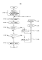
- FIG. 3 is a flowchart of processing performed by the motor model generation unit 3 in the vehicle integrated simulator 1.
- the vehicle integrated simulator 1 can cause the control unit 501 to function as the motor model generation unit 3 and execute the process of FIG. 3 by executing a predetermined program in the control unit 501.
- step S ⁇ b> 101 the motor model generation unit 3 sets a control parameter by the parameter setting unit 23.
- step S102 the motor model generation unit 3 uses the parameter setting unit 23 to execute a parameter setting process for setting a structural parameter and an electrical parameter. Details of the parameter setting process will be described later with reference to FIG.
- step S103 the motor model generation unit 3 executes a parameter confirmation process for confirming the structural parameters and electrical parameters set in step S102. Details of the parameter confirmation processing will be described later with reference to FIG.
- step S104 it is determined whether or not the electrical parameter set in step S102 satisfies the specification of the output request value 21. When the difference between the output value from the motor calculation unit 28 and the output request value 21 falls within a predetermined range, it is determined that the electrical parameter satisfies the specification of the output request value 21, and the process proceeds to step S108. . On the other hand, if not, the process proceeds to step S105, the required torque difference ⁇ is added to the correction value 22, and the process proceeds to step S106.
- step S104 When it is determined in step S104 that the electrical parameter satisfies the specification of the required output value 21, in step S108 and subsequent steps, the optimum electrical parameter is searched with more stringent conditions.
- step S108 the current required torque difference ⁇ and the end condition ⁇ are compared. If the required torque difference ⁇ is smaller than the end condition ⁇ , it is determined that the simulation end condition is satisfied by performing a sufficient search. Proceed to step S110.
- step S110 the obtained electric parameter value is output as the electric parameter 15a. If step S110 is performed, the motor model production
- the required torque difference ⁇ is equal to or greater than the end condition ⁇ , the required torque difference ⁇ is subtracted from the correction value 22 in order to search for a more severe condition, and the process proceeds to step S106.
- step S106 as a search interval reduction process, the torque difference change rate ⁇ is multiplied by the required torque difference ⁇ added to the correction value 22 in step S105 or subtracted from the correction value 22 in step S109.
- step S107 the obtained correction value 22 is stored, and the process returns to step S102.
- the correction value 22 stored here is called in the parameter setting process in the subsequent step S102, and is used for setting the structure parameter.
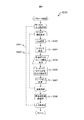
- FIG. 4 is a flowchart of the parameter setting process executed in step S102 of FIG.
- the parameter setting unit 23 executes the parameter setting process shown in FIG. 4 in basically the same procedure as the single unit design of the motor.
- step S201 the output request value 21 is set.
- step S202 the correction value 22 stored in step S107 of FIG. 3 is called and input.
- step S203 a motor structure design process is performed to calculate a structure parameter that satisfies the sum of the output request value 21 set in step S201 and the correction value 22 input in step S202.
- step S204 it is determined whether or not the structural parameter calculated in step S203 satisfies the specifications for the motor. As a result, when it is determined that the specification is satisfied, the process proceeds to step S206, and when it is determined that the specification is not satisfied, the process proceeds to step S205.
- step S205 a structural parameter update process for updating the value of the structural parameter calculated in step S203 is executed, and the motor structural design process in step S203 is performed again.
- the structural design of a motor consists of iterative and convergence calculations, and the processes in steps S203 to S205 are processes for obtaining structural parameters following such a design method.
- step S206 a structural parameter output process for outputting the structural parameter is performed.
- step S207 an electrical parameter calculation process for calculating an electrical parameter using the structural parameter output in step S206 is performed.
- step S208 an electrical parameter output process for outputting the electrical parameter calculated in step S107 is performed. If step S208 is performed, the parameter setting part 23 will complete
- FIG. 5 is a flowchart of the parameter confirmation process executed in step S103 in the figure.
- Step S301 is an iterative process relating to operating points, and the following steps S302 to S308 are respectively performed for all operating points in the operating point list generated by the operating point sweep unit 24.
- Step S302 is an iterative process regarding the overmodulation rate, and the following steps S303 to S307 are respectively performed for the modulation rates of all overmodulation regions generated by the overmodulation rate sweep unit 25.
- step S303 the motor current setting unit 26 sets the d-axis current id and the q-axis current iq.
- step S304 the motor input creation unit 27 creates three-phase voltages Vu, Vv, Vw to be input to the motor plant model 13b based on the d-axis current id and the q-axis current iq set in step S303.
- step S305 the inverter loss calculation unit 30 calculates the inverter loss based on the motor input created in step S304, that is, the three-phase voltages Vu, Vv, and Vw, and outputs the calculation result.
- step S306 the motor calculation unit 28, torque ripple calculation unit 29, and total efficiency calculation unit 31 calculate the output value, torque ripple, and total efficiency of the motor plant model 13b for the motor input created in step S304, respectively.
- step S307 the trade-off evaluation unit 32 calculates a trade-off evaluation based on the torque ripple and total efficiency calculated in step S306.
- the motor model generation unit 3 repeatedly executes the series of processes of steps S303 to S307 described above for each modulation rate as a target of the repetition process of step S302. As a result, a trade-off evaluation result for each modulation factor is obtained.
- step S308 After completing the iterative process in step S302, in step S308, an optimal overmodulation rate is selected based on the result of the trade-off evaluation obtained for each modulation rate.
- the method for selecting the optimum overmodulation rate in step S308 will be described later.
- the motor model generation unit 3 repeatedly executes the series of processes in steps S303 to S308 described above for each operating point as a target of the iterative process in step S301. As a result, an optimal overmodulation rate is selected for each operating point.
- the motor model generation unit 3 ends the parameter confirmation process of FIG. 5 and proceeds to step S104 of FIG.
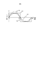
- FIG. 6 is an explanatory diagram of overmodulation.
- the inverter creates an AC voltage to be supplied to the motor by turning the DC voltage on and off with a switching element. Therefore, normally, the maximum value of the AC voltage output from the inverter is equal to or less than the maximum value of the DC voltage.
- a waveform indicated by reference numeral 101 represents a sine wave waveform when the maximum value is equal to the DC voltage.
- the vertical axis of this figure represents the magnitude of the AC voltage, and the AC voltage when equal to the DC voltage is 1.0.
- the effective value of the AC voltage output from the inverter is maximized when the waveform of the AC voltage is a rectangular waveform having a maximum voltage of 1.0 indicated by reference numeral 102.
- a waveform indicated by reference numeral 103 represents a fundamental wave component obtained by subjecting the rectangular wave waveform 102 to Fourier transform. That is, the output voltage of the inverter can be increased up to this point with the voltage shown in the fundamental wave component waveform 103 of the rectangular wave as an upper limit value.
- PWM control used for inverter control the inverter cannot be switched in the region where the absolute value of the voltage exceeds 1.0.
- PWM control performed using a voltage waveform having such a region as a voltage command is referred to as overmodulation PWM control.
- Overmodulation PWM control has the effect of increasing the voltage as described above. Further, since the number of times of switching is reduced, there is an effect of reducing the switching loss of the inverter.
- the sinusoidal shape cannot be reproduced in the region where no pulse is applied, which causes distortion in the waveform of the AC voltage, and there are points to be considered such as increased noise and increased torque ripple. come.
- Modulation rate is generally defined as “amplitude of fundamental component of phase voltage ⁇ (DC voltage / 2)”.
- modulation rate is 1 or more and third harmonic is 1.15 or more Becomes overmodulated.
- a waveform indicated by reference numeral 104 is a voltage waveform in which a third harmonic is superimposed on a sine wave.
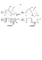
- FIG. 7 is a diagram illustrating an example of a PWM waveform.
- a case where a sine wave is adopted as the voltage command signal is shown.
- overmodulation occurs at a modulation rate of 1.0 or more.
- FIG. 7A shows an example of a PWM waveform without overmodulation
- FIG. 7B shows an example of a PWM waveform with overmodulation.
- the waveform denoted by reference numeral 110 is a comparative triangular wave for creating each PWM waveform.
- the waveform indicated by reference numeral 111a in FIG. 7A is a voltage command when there is no overmodulation, and the waveform indicated by reference numeral 111b in FIG.
- a voltage pulse is output if the voltage commands 111a and 111b are larger than the comparative triangular wave 110, and is set to 0 without outputting a voltage pulse if the voltage commands 111a and 111b are smaller.
- PWM waveforms as indicated by reference numerals 112a and 112b are generated.
- the waveform indicated by reference numeral 112a is a PWM waveform when there is no overmodulation
- the waveform indicated by reference numeral 112b is a PWM waveform when there is overmodulation.
- the PWM waveform 112b has fewer switching times than the PWM waveform 112a. Therefore, it turns out that switching loss can be reduced at the time of overmodulation.
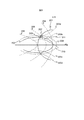
- FIG. 8 is an explanatory diagram of a method for setting the d-axis current id and the q-axis current iq using overmodulation.
- the electrical parameters can be determined, and a set of d-axis current and q-axis current (id, iq) that realizes the operating point ( ⁇ , ⁇ ) (hereinafter referred to as dq pair) is derived. It can.
- dq pair a set of d-axis current and q-axis current that realizes the operating point ( ⁇ , ⁇ )
- dq pair a set of d-axis current and q-axis current that realizes the operating point ( ⁇ , ⁇ )
- dq pair a set of d-axis current and q-axis current that realizes the operating point ( ⁇ , ⁇ )
- dq pair a set of d-axis current and q-axis current that realizes the operating point ( ⁇ , ⁇ )
- ⁇ represents the
- Reference numeral 202 represents a voltage limit ellipse, which changes according to the motor speed ⁇ . As the motor rotation speed ⁇ increases, the voltage limiting ellipse 202 has a property of decreasing. The dq pair is required to be inside this voltage limit ellipse 202.
- Symbols 203a, 203b, 203c, and 203d are all equal torque lines, and are determined according to the torque value.
- the equal torque line 203a is an equal torque line when the torque is ⁇ 1
- the equal torque line 203b is an equal torque line when the torque is ⁇ 2
- the equal torque line 203c is an equal torque line when the torque is ⁇ 2.
- An equal torque line 203d represents an equal torque line when torque - ⁇ 1.
- the minimum copper loss line 204 and the minimum iron loss line 205 in FIG. 8 and the minimum loss line 206 that minimizes the sum of these are determined.
- the intersection of the equal torque lines 203a to 203d and the minimum loss line 206 is a dq pair to be obtained.
- a dq pair that realizes a certain operating point ( ⁇ , ⁇ 1) with maximum efficiency is represented by the intersection of the equal torque line 203a and the minimum loss line 206 indicated by reference numeral 207.
- This intersection point that is, the dq pair 207 is in the current limit circle 201 but not in the voltage limit ellipse 202 at the rotational speed ⁇ . Therefore, it can be seen that the dq pair 207 having the maximum efficiency cannot be realized. Therefore, when a point inside the voltage limit ellipse 202 on the equal torque line 203a is searched, this time, the point goes out of the current limit circle 201. Therefore, it can be seen that the operating point ( ⁇ , ⁇ 1) cannot be realized.
- the dq pair that can be operated by the motor is represented by the intersection indicated by reference numeral 208 due to the restrictions on the current and voltage, and deviates from the equal torque line 203a.
- a dq pair that realizes the operating point ( ⁇ , ⁇ 2) with the maximum efficiency is represented by the intersection of the equal torque line 203b and the minimum loss line 206 indicated by reference numeral 210. Since this intersection point, that is, the dq pair 210 is on the minimum loss line 206 that is the highest efficiency, and further inside both the current limiting circle 201 and the voltage limiting ellipse 202, the motor alone can be operated with the highest efficiency.
- overmodulation has an effect of reducing inverter loss by reducing switching loss, there is a possibility that a dq pair 211 having higher efficiency than the dq pair 210 may exist in the overall efficiency.
- overmodulation has a disadvantageous property (hereinafter referred to as “penalty”) in terms of vehicle characteristics, that is, torque ripple caused by voltage distortion. Therefore, it is necessary to consider the effect of these penalties during overmodulation.
- the trade-off evaluation unit 32 in FIG. 2 operates so as to maximize the score (hereinafter referred to as “reward”) obtained by quantifying the profit and loss set by the efficiency and the penalty.
- reward efficiency-penalty.
- the penalty is the magnitude of torque ripple.
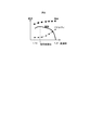
- FIG. 9 is a diagram illustrating an example of the relationship between the modulation rate, efficiency, penalty, and reward.
- the trade-off evaluation unit 32 employs a modulation rate that maximizes the reward in FIG.
- the same reward evaluation formula is used at all operating points.
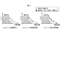
- FIG. 10 is an explanatory diagram of an operating point determination method using a conventional method.
- FIG. 10 shows three operating point determination methods.
- FIG. 10A shows the case of no overmodulation with a modulation rate of less than 1.15
- FIG. 10B shows the case of intermediate overmodulation with a variable rate of 1.21
- FIG. 10C shows the case of maximum overmodulation with a modulation rate of 1.27.
- white circles indicate the operating points to be searched, and black circles indicate the operating points that are employed for each modulation factor.
- FIG. 10A since there is no black circle, there is no operating point that can be adopted in the case of no overmodulation.
- FIG. 10B and FIG. It can be seen that sometimes any operating point can be employed.
- the operating point is determined using only the voltage expansion effect due to overmodulation.
- overmodulation is limited to only the high speed region, and normal modulation rate control without overmodulation is performed in a region where overmodulation is not necessarily required, that is, in the hatched region of FIG.
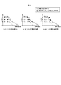
- FIG. 11 is an explanatory diagram of an operating point determination method when the vehicle integrated simulator 1 according to the first embodiment of the present invention is used.
- the definitions of white circles and black circles in FIG. 11 and the modulation rates in the three operating point determination methods shown in FIGS. 11A, 11B, and 11C are the same as those in FIG.
- the inverter loss reduction effect due to overmodulation is estimated for all the operating points of the motor set by the operating point sweep unit 24. As a result, a region where overmodulation occurs may appear even in a region where overmodulation is not required in the conventional design method.
- FIG. 11 is an explanatory diagram of an operating point determination method when the vehicle integrated simulator 1 according to the first embodiment of the present invention is used.
- the definitions of white circles and black circles in FIG. 11 and the modulation rates in the three operating point determination methods shown in FIGS. 11A, 11B, and 11C are the same as those in FIG.
- the inverter loss reduction effect due to overmodulation is estimated for all the operating points of
- the motor model generation unit 3 includes an operating point sweep unit 24, a parameter setting unit 23, a motor input creation unit 27, a motor calculation unit 28, and a correction unit 34.
- the operating point sweep unit 24 outputs an operating point inside the motor operating region based on the output request value 21 related to the motor mounted on the vehicle.
- the parameter setting unit 23 sets structural parameters related to the motor structure.
- the motor input creation unit 27 creates an input value to the motor plant model 13b that models the motor based on the operating point output from the operating point sweep unit 24.
- the motor calculation unit 28 calculates an output value with respect to an input value using the motor plant model 13b based on the electrical parameter regarding the electrical characteristics of the motor set by the parameter setting unit 23 based on the structural parameter.
- the correction unit 34 changes the structural parameter so that the output value calculated by the motor calculation unit 28 approaches the output request value 21.
- the simulation program stored in the storage unit 502 is a program that can be executed by the control unit 501 that is a computer, and causes the control unit 501 to function as each unit of the motor model generation unit 3. Since it did in this way, the motor design which looked at the whole vehicle system is realizable.
- the motor input creation unit 27 creates an input value to the motor plant model 13b including the overmodulation region of the motor.
- the motor model generation unit 3 further includes an overmodulation rate sweep unit 25 that outputs a modulation rate in the overmodulation region of the motor.
- the motor input creation unit 27 creates an input value to the motor plant model 13b based on the operating point output from the operating point sweep unit 24 and the modulation rate output from the overmodulation rate sweep unit 25. Since it did in this way, it becomes possible to design the highly efficient motor using the efficiency improvement effect by overmodulation.
- the motor model generation unit 3 further includes a trade-off evaluation unit 32 that performs a trade-off evaluation between a motor efficiency improvement effect in the overmodulation region and a disadvantage due to an increase in torque ripple. Since it did in this way, it becomes possible to set the modulation factor in consideration of the balance between the advantage of efficiency improvement in the overmodulation region and the penalty due to torque ripple.
- the vehicle integrated simulator 1 further includes a plant model entity database 40.
- the control unit 501 of the vehicle integrated simulator 1 is connected to a storage unit 502 including the plant model entity database 40.
- the motor calculation unit 28 refers to the plant model entity database 40 and acquires the motor plant model 13b. Since it did in this way, when the design change of a motor is performed, the whole vehicle integrated simulator 1 can be easily made to respond to the said design change.
- the above-mentioned pulse-saving PWM method is a method in which a PWM waveform with a reduced number of pulses is derived in advance so that harmonic components included in the voltage waveform are reduced, and an appropriate PWM waveform is selected according to the operating point. It is.
- the PWM waveform used here is determined in advance so as to eliminate odd-order harmonics such as third order, fifth order, and seventh order. Since such a voltage waveform adjustment method is well known, the details are omitted.
- the hardware configuration of the vehicle integration simulator according to the present embodiment is the same as the hardware configuration of FIG. 1 described in the first embodiment. Therefore, description of the hardware configuration of this embodiment is omitted below.
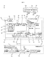
- FIG. 12 is a diagram showing a software configuration of the vehicle integration simulator according to the second embodiment of the present invention.
- the vehicle integrated simulator 1a of the present embodiment includes an overall vehicle model 2, a motor model generation unit 3a, and a plant model entity database 40 as functions on the software configuration.
- the vehicle overall model 2 and the plant model entity database 40 are the same as those in the first embodiment shown in FIG.
- the motor model generation unit 3a is obtained by replacing the overmodulation rate sweep unit 25 with a pulse-saving PWM waveform selection unit 35 in the motor model generation unit 3 in the first embodiment shown in FIG.
- the pulse-saving PWM waveform selection unit 35 selects a PWM waveform in the pulse-saving PWM control region of the motor and outputs it to the motor current setting unit 26.
- the pulse-saving PWM control region is a motor control region that outputs a PWM waveform with the number of pulses reduced so that harmonic components included in the voltage waveform are reduced as described above. This corresponds to a region having a modulation rate equal to or higher than the above. Note that the PWM waveform selected in the pulse-saving PWM control region by the pulse-saving PWM waveform selection unit 35 varies depending on the modulation rate and the order of harmonics to be reduced.
- the motor current setting unit 26 is based on the operating point output from the operating point sweep unit 24 and the PWM waveform in the pulse-saving PWM control region output from the pulse-saving PWM waveform selection unit 35. , D-axis current id and q-axis current iq are calculated. The operation of each other part is the same as that of the motor model generation part 3. Further, the motor model generation unit 3a is described in the first embodiment except that in the parameter confirmation processing of FIG. 5, the iterative processing of step S302 is performed for all the PWM waveforms selected by the pulse-saving PWM waveform selection unit 35. The same processing as that performed is executed.
- FIG. 13 is an explanatory diagram of a PWM waveform selection method in the pulse-saving PWM method.
- FIG. 13 shows an example of a PWM waveform selected for each operating point in the pulse-saving PWM control region.
- the numbers in each white circle indicating the operating points represent the types of PWM waveforms. Specifically, “1” is a normal PWM waveform that is not the pulse-saving PWM method, “2”, “3”, and “4” are PWM waveforms that are in the pulse-saving PWM method, and “5” is a rectangular wave. Represents each. These PWM waveforms can be set in advance for each operating point based on the evaluation result by the trade-off evaluation unit 32.
- the pulse-saving PWM method like overmodulation, has a voltage expansion effect and can handle rectangular waves. Furthermore, since the waveform with the reduced number of pulses is taken into account, the effect of reducing inverter switching loss is obtained as in the case of overmodulation.
- the vehicle integrated simulator 1a of the present embodiment it is possible to design a motor that can obtain these effects.
- the motor model generation unit 3a includes an operating point sweep unit 24, a parameter setting unit 23, a motor input generation unit 27, and the motor model generation unit 3 according to the first embodiment.
- the motor calculation unit 28 and the correction unit 34 are provided. Therefore, similarly to the first embodiment, it is possible to realize a motor design that looks at the entire vehicle system.
- the motor input creation unit 27 creates an input value to the motor plant model 13b including the pulse-saving PWM control region of the motor.
- the motor model generation unit 3a further includes a pulse-saving PWM waveform selection unit 35 that selects a PWM waveform in the pulse-saving PWM control region of the motor.
- the motor input creation unit 27 creates an input value to the motor plant model 13b based on the operating point output from the operating point sweep unit 24 and the PWM waveform selected by the pulse-saving PWM waveform selection unit 35. Since it did in this way, it becomes possible to design the highly efficient motor using the efficiency improvement effect by a pulse-saving PWM system.
- the motor model generation unit 3a further includes a trade-off evaluation unit 32 that performs a trade-off evaluation between a motor efficiency improvement effect and a disadvantage due to an increase in torque ripple in the pulse-saving PWM control region. Since it did in this way, it becomes possible to set the modulation factor in consideration of the balance between the advantage of efficiency improvement in the pulse-saving PWM control region and the penalty due to torque ripple.
- the vehicle integrated simulator 1a includes a plant model entity database 40 as in the vehicle integrated simulator 1 according to the first embodiment, and the motor calculation unit 28 refers to the plant model entity database 40 to obtain a motor plant model. 13b is acquired. Therefore, as in the first embodiment, when the motor design is changed, the entire vehicle integrated simulator 1a can be easily adapted to the design change.
- the hardware configuration of the vehicle integration simulator according to the present embodiment is the same as the hardware configuration of FIG. 1 described in the first embodiment, as in the second embodiment. Therefore, description of the hardware configuration of this embodiment is omitted below.
- FIG. 14 is a diagram showing a software configuration of the vehicle integration simulator according to the third embodiment of the present invention.
- the vehicle integrated simulator 1b of the present embodiment includes a vehicle overall model 2, a motor model generation unit 3b, and a plant model entity database 40 as functions on the software configuration.
- the vehicle overall model 2 and the plant model entity database 40 are the same as those in the first embodiment shown in FIG.
- the motor model generation unit 3b includes both the overmodulation rate sweep unit 25 in the first embodiment shown in FIG. 2 and the pulse-saving PWM waveform selection unit 35 in the second embodiment shown in FIG. It is.
- the motor current setting unit 26 selects the operation point output from the operation point sweep unit 24, the modulation rate in the overmodulation region output from the overmodulation rate sweep unit 25, and the pulse-saving PWM waveform selection. Based on the PWM waveform in the pulse-saving PWM control region output from the unit 35, the d-axis current id and the q-axis current iq are calculated. However, only one of the modulation rate from the overmodulation rate sweep unit 25 and the PWM waveform from the pulse-saving PWM waveform selection unit 35 may be used. The operation of each other part is the same as that of the motor model generation part 3.
- FIG. 15 is a diagram showing a hardware configuration of a motor simulator according to the fourth embodiment of the present invention.
- the motor simulator 10 shown in FIG. 15 has the vehicle integrated simulator 1 in the first embodiment shown in FIG. 1 except that the control unit 501 functions only as the motor model generation unit 3 and does not function as the overall vehicle model 2. It has the same composition as.
- the motor model generation unit 3 is realized by the software configuration shown in FIG. Instead of the motor model generation unit 3, the motor model generation unit 3a shown in FIG. 12 or the motor model generation unit 3b shown in FIG. 14 may be used.
- the fourth embodiment of the present invention described above has the same operational effects as those described in the first and second embodiments.
- the motor computing unit 28 can refer to the motor plant model 13 stored in the plant model entity database 40, so that the motor plant model can be managed in an integrated manner. Thereby, there exists an effect that the change of a motor plant model becomes easy.
Landscapes
- Engineering & Computer Science (AREA)
- Theoretical Computer Science (AREA)
- Physics & Mathematics (AREA)
- General Physics & Mathematics (AREA)
- Business, Economics & Management (AREA)
- Computer Hardware Design (AREA)
- Evolutionary Computation (AREA)
- Geometry (AREA)
- General Engineering & Computer Science (AREA)
- Power Engineering (AREA)
- Human Resources & Organizations (AREA)
- General Business, Economics & Management (AREA)
- Economics (AREA)
- General Health & Medical Sciences (AREA)
- Manufacturing & Machinery (AREA)
- Marketing (AREA)
- Primary Health Care (AREA)
- Strategic Management (AREA)
- Tourism & Hospitality (AREA)
- Health & Medical Sciences (AREA)
- Life Sciences & Earth Sciences (AREA)
- Sustainable Development (AREA)
- Sustainable Energy (AREA)
- Transportation (AREA)
- Mechanical Engineering (AREA)
- Electric Propulsion And Braking For Vehicles (AREA)
- Control Of Electric Motors In General (AREA)
- Management, Administration, Business Operations System, And Electronic Commerce (AREA)
- Control Of Ac Motors In General (AREA)
Abstract
車両システム全体を見据えたモータ設計を実現する。 車両統合シミュレータ1において、動作点スイープ部24は、車両に搭載されるモータに関する出力要求値21に基づいて、モータ動作領域内部の動作点を出力する。パラメータ設定部23は、モータの構造に関する構造パラメータを設定する。モータ入力作成部27は、動作点スイープ部24から出力された動作点に基づいて、モータをモデル化したモータプラントモデル13bへの入力値を作成する。モータ演算部28は、パラメータ設定部23で構造パラメータに基づき設定されたモータの電気的特性に関する電気パラメータに基づいて、入力値に対する出力値をモータプラントモデル13bを用いて演算する。補正部34は、モータ演算部28で演算された出力値が出力要求値21に近づくように、構造パラメータを変更する。
Description
本発明は、モータモデルシミュレーションプログラム、モータシミュレータ、および車両統合シミュレータに関する。
車両システムは数多くの部品の組合せからなる複雑なシステムである。近年、車両に求められる機能は低燃費化や安全性能の強化などますます高度化かつ複雑化している。しかも、市場要求は年々変化するため、開発期間を短縮して顧客ニーズにできるだけ早く対応することが求められる。
上記課題を実現するための一手法として、車両統合シミュレータの利用が進められている。これは、車両全体の挙動をコンピュータなどを用いてシミュレートできるように数式化、あるいはプログラム化しておき、実車によらず計算で車両の性能を見積もることを目的とするものである。以降、数式やプログラムを「モデル」と称し、またモデルを用いてシミュレーション可能な状態とすることを「モデル化」と称す。
車両統合シミュレータを用いれば、これまでは車両を試作することによって性能評価を行っていたところを、計算機上で性能評価を行うことができるようになる。そのため、試作よりも多くの設計案を評価することができるため、より顧客要求にふさわしい設計を選択することができるようになる。また、試作によらなければ評価できない部分以外は試作費用を削減できるため、開発コストの低減が見込める。さらに、一般的に試作より車両統合シミュレータのほうが評価にかかる時間が短いために、開発期間の低減が期待できる。
車両統合シミュレータは通常、MATLAB(登録商標)やSimulink(登録商標)などの制御系CADを用いて実現される。一般にこれらの制御系CADでは、ブロックの組合せにより全体システムを構築する。ブロックは、入力および内部状態から出力を計算するひとまとまりのモデルを指す。ブロックの大きさ(以降「粒度」と記載する)は自由に設定することができるが、一般的には車両を構成する一部品を一ブロックとすることが多い。この場合、部品特性の違いは、各ブロックのパラメータ値を変更することで実現される。部品ごとにブロックを作成しておけば、実際に部品を交換した際、対応する部分のブロックの交換のみで車両統合シミュレータは対処できるため、変更にかかる工数が減少する。また、部品ごとにブロックを作成することで、各部品作成メーカがそれぞれのブロックの設計を並行して行えるため、開発期間が短くなるという利点がある。
これまで車両統合シミュレータは、主に燃費評価や走行性能評価といった用途に利用されてきた。しかし近年では、更なる開発期間短縮の要求を受け、さまざまな特性を有する部品を適用した際の車両特性を計算し、その計算結果を比較して車両に最適な部品を選定するという試みも行われている。特に、今後市場の伸びが期待されている電気自動車やハイブリッド自動車においては、モータの選定が車両性能に直結するため、モータ選定の重要性がますます増加しつつある。
従来のモータシミュレーション技術として、特許文献1に記載の方法が知られている。特許文献1には、コンピュータ上でモータの効率を求める3次元磁界解析において、最適進角値を求めることが可能な進角値のシミュレーション方法が開示されている。
最近の電気自動車やハイブリッド自動車では、モータに交流電力を供給するインバータの制御を工夫して、モータの動作領域を拡大したり、電気系の総合効率を向上したりする手法が提案されている。この場合、インバータ制御まで含めて車両システム全体を見据えたモータ設計が望ましいが、特許文献1に開示された従来のシミュレーション方法では、車両システム全体を見据えたモータ設計は困難であった。
本発明によるモータモデルシミュレーションプログラムは、コンピュータにより実行可能なものであって、前記コンピュータを、車両に搭載されるモータに関する出力要求値に基づいて、モータ動作領域内部の動作点を出力する動作点スイープ部と、前記モータの構造に関する構造パラメータを設定するパラメータ設定部と、前記動作点に基づいて、前記モータをモデル化したモータモデルへの入力値を作成するモータ入力作成部と、前記構造パラメータに基づき設定された前記モータの電気的特性に関する電気パラメータに基づいて、前記入力値に対する出力値を前記モータモデルを用いて演算するモータ演算部と、前記出力値が前記出力要求値に近づくように、前記構造パラメータを変更する補正部と、として機能させる。
本発明によるモータシミュレータは、車両に搭載されるモータに関する出力要求値に基づいて、モータ動作領域内部の動作点を出力する動作点スイープ部と、前記モータの構造に関する構造パラメータを設定するパラメータ設定部と、前記動作点に基づいて、前記モータをモデル化したモータモデルへの入力値を作成するモータ入力作成部と、前記構造パラメータに基づき設定された前記モータの電気的特性に関する電気パラメータに基づいて、前記入力値に対する出力値を前記モータモデルを用いて演算するモータ演算部と、前記出力値が前記出力要求値に近づくように、前記構造パラメータを変更する補正部と、を備える。
本発明による車両統合シミュレータは、車両に搭載されるモータをモデル化したモータモデルを生成するモータモデル生成部と、前記車両を構成する部品をそれぞれモデル化した複数のブロックを有し、前記ブロックは前記モータモデルを少なくとも含む車両全体モデルと、を備え、前記モータモデル生成部は、前記モータに関する出力要求値に基づいて、モータ動作領域内部の動作点を出力する動作点スイープ部と、前記モータの構造に関する構造パラメータを設定するパラメータ設定部と、前記動作点に基づいて、前記モータモデルへの入力値を作成するモータ入力作成部と、前記構造パラメータに基づき設定された前記モータの電気的特性に関する電気パラメータに基づいて、前記入力値に対する出力値を前記モータモデルを用いて演算するモータ演算部と、前記出力値が前記出力要求値に近づくように、前記構造パラメータを変更する補正部と、を備える。
本発明によれば、車両システム全体を見据えたモータ設計を実現できる。
(車両統合シミュレータの概要)
初めに、本発明に係る車両統合シミュレータの概要を説明する。本発明に係る車両統合シミュレータは、電気モータにより走行可能な電気自動車やハイブリッド自動車等の電動車両について、実際の車両の走行条件を模擬し、その際の車両の各部品の挙動をシミュレーションにより求めるものである。こうした車両統合シミュレータの使用は、要求特性を満足する部品の選定に好適である。
初めに、本発明に係る車両統合シミュレータの概要を説明する。本発明に係る車両統合シミュレータは、電気モータにより走行可能な電気自動車やハイブリッド自動車等の電動車両について、実際の車両の走行条件を模擬し、その際の車両の各部品の挙動をシミュレーションにより求めるものである。こうした車両統合シミュレータの使用は、要求特性を満足する部品の選定に好適である。
一般的に電動車両用モータには三相交流モータが用いられることが多く、その駆動制御にはインバータが用いられる。そのため、モータの性能はインバータの動作によっても左右される。本発明に係る車両統合シミュレータは、インバータの動作も考慮して、総合的にモータの電気パラメータを決定するものである。これにより、車両設計者が本シミュレータを用いる場合の使い勝手の改善や省力化に寄与している。
(第1の実施形態)
以下、本発明の第1の実施形態を、図面を用いて説明する。図1は、本発明の一実施形態に係る車両統合シミュレータのハードウェア構成を示す図である。図1に示す車両統合シミュレータ1は、制御部501、記憶部502、表示部503および操作入力部504を備えている。
以下、本発明の第1の実施形態を、図面を用いて説明する。図1は、本発明の一実施形態に係る車両統合シミュレータのハードウェア構成を示す図である。図1に示す車両統合シミュレータ1は、制御部501、記憶部502、表示部503および操作入力部504を備えている。
制御部501は、たとえばCPU、ROM、RAM等により構成されるコンピュータである。制御部501は、記憶部502に記憶されている不図示のシミュレーションプログラムを実行することで、車両全体モデル2およびモータモデル生成部3として機能する。なお、車両全体モデル2およびモータモデル生成部3の詳細については、後で図2を参照して説明する。
記憶部502は、たとえばハードディスクドライブ(HDD)、ソリッドステートドライブ(SSD)等により構成される不揮発性の記憶装置である。記憶部502には、前述のシミュレーションプログラムに加えて、車両全体モデル2およびモータモデル生成部3で利用されるプラントモデル実体データベース40が記憶されている。なお、プラントモデル実体データベース40の詳細については、後で図2を参照して説明する。
表示部503は、たとえば液晶ディスプレイ等により構成され、車両全体モデル2やモータモデル生成部3で行われたシミュレーション結果を表示して車両設計者等のユーザに提示する。操作入力部504は、たとえばキーボードやマウス等により構成され、ユーザからの操作入力を検出して制御部501に通知する。
図2は、本発明の第1の実施形態に係る車両統合シミュレータのソフトウェア構成を示す図である。図2に示すように、本実施形態の車両統合シミュレータ1は、ソフトウェア構成上の機能として、車両全体モデル2、モータモデル生成部3およびプラントモデル実体データベース40を備えている。
車両全体モデル2は、シミュレーション対象車両を構成する部品をそれぞれモデル化したインバータ制御モデル11、インバータプラントモデル12a、モータプラントモデル13aおよびギアボックスプラントモデル14を有している。これらのモデルは、インバータ制御装置、インバータ、モータ、ギアボックスの各部品の挙動を導出するものであり、たとえばMATLAB(登録商標)やSimulink(登録商標)などの制御系1次元CADにおけるブロック(計算のひとまとまり)として表現される。ただし、他のモデル表現形式、たとえば数式、表(マップ)形式、C言語等によって実現されるコンピュータプログラムなどであってもよい。なお、車両全体モデル2は、実際には構成要素が非常に多く複雑であるため、図2では説明の簡素化のために、モータモデル生成部3と関係のある部分のみを抽出して図示している。
インバータ制御モデル11は、インバータの要求トルクと要求回転数を入力として、インバータの制御信号を作成するブロックである。インバータプラントモデル12aは、インバータ制御モデル11で作成されたインバータの制御信号と、バッテリからインバータに供給される直流電圧やインバータからモータに出力される交流電流を入力として、インバータに流れる直流電流やインバータからモータに印加される交流電圧を計算するブロックである。モータプラントモデル13aは、モータに印加される交流電圧とモータ回転数からモータのトルクや交流電流を計算するブロックである。ギアボックスプラントモデル14は、モータの出力トルクを用いて車軸の出力トルクを計算するブロックである。
図2において、インバータプラントモデル12aとモータプラントモデル13aは、破線でそれぞれ示されている。インバータプラントモデル12aはタグBを介して、またモータプラントモデル13aはタグAを介して、プラントモデル実体データベース40に記憶されたインバータプラントモデル12、モータプラントモデル13をそれぞれ参照するような構成としている。プラントモデル実体データベース40に記憶されたこれらのプラントモデルは、インバータとモータをそれぞれモデル化した各プラントモデルの実体を表している。すなわち、プラントモデル実体データベース40に記憶されたインバータプラントモデル12およびモータプラントモデル13とそれぞれ同一の内容が、インバータプラントモデル12aおよびモータプラントモデル13aとして、車両全体モデル2に反映される。
モータモデル生成部3は、パラメータ設定部23、動作点スイープ部24、過変調率スイープ部25、モータ電流設定部26、モータ入力作成部27、モータ演算部28、トルクリプル演算部29、インバータ損失演算部30、総合効率演算部31、トレードオフ評価部32、評価結果保管部33および補正部34を有している。モータモデル生成部3には、ユーザにより決定された出力要求値21が入力される。出力要求値21は、たとえばモータ体格や目標トルク、最高回転数など、車両特性に関係するモータの設計要求値のことである。モータモデル生成部3に入力された出力要求値21は、補正部34からの補正値22と加算されることで補正され、パラメータ設定部23、動作点スイープ部24およびインバータ損失演算部30に入力される。
パラメータ設定部23は、入力された補正後の出力要求値21、すなわち出力要求値21と補正値22の加算値に基づいて、モータの挙動に関係する物理量または設定値を表すモータのパラメータを設定する。モータのパラメータにはさまざまなものがあるが、以下の説明では、モータのパラメータをその特性に応じて、「構造バラメータ」、「電気パラメータ」、「制御パラメータ」の3つに分類する。構造パラメータは、モータの軸長や内径、磁石の厚さなど、モータの形状や構造に関係するパラメータである。電気パラメータは、バッテリ電圧、d軸インダクタンスやq軸インダクタンス、巻線抵抗など、モータの挙動をシミュレートする上で計算に直接用いられる、モータの電気的特性に関係するパラメータである。電気パラメータには、構造パラメータにより決定されるものが含まれる。制御パラメータは、主にモータ演算部28への入力作成に用いられる、モータの制御条件に関係するパラメータであり、たとえばq軸電流、d軸電流、直流電圧などの条件が相当する。また、後述する評価関数の重みや学習係数など、電気パラメータを収束計算させる際の調整パラメータも制御パラメータに含まれる。パラメータ設定部23は、周知のモータ設計手順に従って構造パラメータと電気パラメータを反復計算により設定(仮決定)すると共に、ユーザに与えられた制御条件に従って制御パラメータを設定し、各パラメータ値をモータ電流設定部26、モータ演算部28および補正部34に出力する。
動作点スイープ部24は、入力された補正後の出力要求値21、すなわち出力要求値21と補正値22の加算値に基づいて、モータの動作を確認するためのモータ動作領域内部の動作点として、モータに要求される最大回転数と最大トルクの組み合わせを生成する。最大回転数と最大トルクの組み合わせは複数個存在するため、動作点スイープ部24は、出力要求値21に応じて複数の動作点を生成し、リスト化してモータ電流設定部26に出力する。動作点スイープ部24が出力するリスト化された複数の動作点をまとめて、以下では「動作点リスト」と記載する。
過変調率スイープ部25は、モータの過変調領域における変調率を生成し、モータ電流設定部26に出力する。変調率は、「相電圧の基本波成分の振幅÷(直流電圧/2)」として定義される値であり、一般的には、相電圧が正弦波の場合は変調率1以上、正弦波に3次高調波を重畳させた場合は変調率1.15以上の領域を過変調領域と称する。過変調は周知のようにインバータの出力最大電圧を拡大することができる技術であり、この過変調によって電圧を上げれば、モータはより効率が良く、かつ回転数を上げられる効果がある。その反面、過変調を行わない場合と比較して、電流リプルの増大によるノイズやトルク変動の影響を考える必要が出てくる。上記の3次高調波を重畳させた相電圧の場合、変調率1.15から理論上の変調率の最大値1.27までの範囲では、こうした影響が現れてくることが知られている。そのため、過変調率スイープ部25は、たとえば変調率1.15(3次高調波重畳の場合)から変調率1.27まで少しずつ、たとえば0.01間隔などで変調率を変化させ、モータ電流設定部26に出力する。
モータ電流設定部26は、動作点スイープ部24から出力された動作点と、過変調率スイープ部25から出力された過変調領域における変調率とに基づいて、モータ制御信号を作成するための重要な物理量であるd軸電流idおよびq軸電流iqを計算する。具体的には、動作点スイープ部24が生成した動作点リストから動作点を一つずつ取り出し、その動作点で変調率を変化させながらd軸電流idおよびq軸電流iqを計算することにより、各動作点での変調率ごとのd軸電流idとq軸電流iqの値を計算する。このときモータ電流設定部26は、パラメータ設定部23で設定された制御パラメータを用いて、周知の計算手法によりd軸電流idおよびq軸電流iqの計算を行う。
モータ入力作成部27は、モータ電流設定部26で計算されたd軸電流idおよびq軸電流iqの値に基づいてd軸電圧Vdおよびq軸電圧Vqを計算し、さらに計算したd軸電圧Vdおよびq軸電圧Vqの値に基づいて2相-3相変換を行うことで、モータに印加される三相電圧Vu,Vv,Vwを計算する。モータ入力作成部27で計算された三相電圧Vu,Vv,Vwは、モータ演算部28およびインバータ損失演算部30に出力される。
モータ電流設定部26およびモータ入力作成部27は、以上説明したような処理をそれぞれ行う。これにより、動作点スイープ部24で設定された動作点と、過変調率スイープ部25で設定された変調率とに基づいて、モータ演算部28内のモータプラントモデル13bへの入力値としての三相電圧Vu,Vv,Vwを作成することができる。なお、過変調領域においてモータを使用しない場合は、モータプラントモデル13bへの入力値を作成する際に、過変調率スイープ部25で設定された変調率を用いる必要はない。
モータ演算部28は、モータプラントモデル13bを用いて、モータプラントモデル13bへの入力値である三相電圧Vu,Vv,Vwに対する出力値を演算する。この出力値には、たとえばモータに流れる三相電流Iu,Iv,Iwや、モータが出力するトルクなどが含まれる。このときモータ演算部28は、パラメータ設定部23で設定(仮決定)された電気パラメータに基づいて、モータプラントモデル13bの演算を行う。モータプラントモデル13bは、車両全体モデル2におけるモータプラントモデル13aと同様に、モータに印加される交流電圧とモータ回転数からモータのトルクや交流電流を計算するブロックであり、タグAを介して、プラントモデル実体データベース40に記憶されたモータプラントモデル13を参照するような構成としている。なお、モータプラントモデル13bもモータプラントモデル13aと同様に、図2において破線で示されている。
トルクリプル演算部29は、モータ演算部28で演算されたトルクに基づいて、モータのトルクリプルを演算する。
インバータ損失演算部30は、インバータの等価回路モデルであるインバータプラントモデル12bを用いて、インバータ損失を演算する。具体的には、モータ入力作成部27で計算された三相電圧Vu,Vv,Vwと、モータ演算部28で演算された三相電流Iu,Iv,Iwと、補正後の出力要求値21とに基づき、損失=電圧×電流の式を時々刻々適用して、スイッチング損失を含めたインバータ損失を計算する。インバータプラントモデル12bは、車両全体モデル2におけるインバータプラントモデル12aと同様のものであり、タグBを介して、プラントモデル実体データベース40に記憶されたインバータプラントモデル12を参照するような構成としている。なお、インバータプラントモデル12bもインバータプラントモデル12aと同様に、図2において破線で示されている。
総合効率演算部31は、インバータ損失演算部30で演算されたインバータ損失と、モータ演算部28においてモータプラントモデル13bから演算される銅損および鉄損とに基づいて、モータの総合効率を演算する。この総合効率は、過変調領域におけるモータの効率向上効果を表している。
トレードオフ評価部32は、トルクリプル演算部29で演算されたトルクリプルと、総合効率演算部31で演算された総合効率とに基づいて、過変調領域におけるモータの効率向上効果とトルクリプル増加による不利益とのトレードオフ評価を行う。トレードオフ評価部32は、動作点スイープ部24が生成した動作点リストの各動作点と、過変調率スイープ部25から出力された各変調率との組み合わせごとに、トレードオフ評価を行う。トレードオフ評価部32によるトレードオフ評価の結果は、評価結果保管部33に保管される。なお、トレードオフ評価部32が行うトレードオフ評価の詳細については、後で説明する。
補正部34は、評価結果保管部33に保管されたトレードオフ評価結果に基づいて最適な動作点と変調率を抽出し、出力要求値21に対する補正値22を作成する。この補正値22に基づいてパラメータ設定部23がパラメータの再設定を行うことで、モータ演算部28からの出力値が出力要求値21に近づくように、構造パラメータおよび電気パラメータが変更される。さらに補正部34は、所定のシミュレーション終了条件を満足したか否かを判断し、満足したと判断した場合には、そのときの電気パラメータの値を電気パラメータ15aとして車両全体モデル2に出力する。車両全体モデル2では、この電気パラメータ15aに基づいて、モータプラントモデル13aの計算が行われる。
プラントモデル実体データベース40は、前述のように、インバータプラントモデル12a、12bおよびモータプラントモデル13a、13bからそれぞれ参照される実体としてのインバータプラントモデル12およびモータプラントモデル13を記憶している。プラントモデル実体データベース40は、たとえばハッシュテーブル、連想リスト、リレーショナルデータベースなどによって実現可能である。なお、実体としてのインバータプラントモデル12およびモータプラントモデル13は、たとえばコンピュータにより実行可能なプログラムによって実現される。また、インバータプラントモデル12およびモータプラントモデル13の参照は、たとえばこれらのプログラムを指定するアドレスやポインタによって実現される。具体的には、たとえばモータプラントモデル13aは、前述の電気パラメータ15aをプログラムの引数として、プラントモデル実体データベース40に記憶されたモータプラントモデル13を指し示すアドレスを関数呼び出しするといった手続きで実行可能である。モータ演算部28においてモータプラントモデル13bを用いた演算を行う場合も同様である。
上記のようにすることで、たとえばプラントモデル実体データベース40においてモータプラントモデル13を変更すると、その変更がモータプラントモデル13a、13bにもそれぞれ同時に反映される。そのため、各モデル間での整合性が確保される。したがって、たとえば使用するモータが磁石モータから誘導モータに設計変更されたような場合でも、プラントモデル実体データベース40内のモータプラントモデル13の変更のみで、車両統合シミュレータ1の全体を当該設計変更に対処できるという効果がある。
上述のように、本実施形態による車両統合シミュレータ1は、車両全体モデル2に加えて、モータモデル生成部3を有している。モータモデル生成部3は、モータの構造パラメータのみならず過変調といったインバータの制御方式も考慮に入れた上で、モータの電気パラメータを作成するという特徴がある。そのため、必ずしもモータの設計に熟達していない設計者であっても、モータ特性を変化させて車両に適したモータ仕様を試してみることが容易になる。
図3は、車両統合シミュレータ1においてモータモデル生成部3が行う処理のフローチャートである。車両統合シミュレータ1は、制御部501において所定のプログラムを実行することで、制御部501をモータモデル生成部3として機能させ、図3の処理を実行させることができる。
まずステップS101において、モータモデル生成部3は、パラメータ設定部23により制御パラメータを設定する。ここでは、たとえば初期補正値(=0)、要求トルク差分Δτの初期値、トルク差分変化率α(0<α<1なる定数)および終了条件εの各制御パラメータを設定する。
ステップS102において、モータモデル生成部3は、パラメータ設定部23により、構造パラメータおよび電気パラメータの設定を行うためのパラメータ設定処理を実行する。パラメータ設定処理の詳細については、後で図4を参照して説明する。
ステップS103において、モータモデル生成部3は、ステップS102で設定した構造パラメータおよび電気パラメータを確認するためのパラメータ確認処理を実行する。パラメータ確認処理の詳細については、後で図5を参照して説明する。
ステップS104以降の処理は、補正部34において実施されることで、補正値22を更新する処理である。ステップS104では、ステップS102で設定した電気パラメータが出力要求値21の仕様を満足しているか否かを判断する。モータ演算部28からの出力値と出力要求値21との差分が所定の範囲内となった場合には、電気パラメータが出力要求値21の仕様を満足していると判断してステップS108に進む。一方、そうでない場合はステップS105に進み、補正値22に要求トルク差分Δτを加算してステップS106に進む。
ステップS104で電気パラメータが出力要求値21の仕様を満足していると判断した場合、ステップS108以降では、さらに条件を厳しくして最適な電気パラメータの探索を行う。ステップS108では、現在の要求トルク差分Δτと終了条件εとを比較し、要求トルク差分Δτが終了条件εよりも小さければ、十分に探索が行われることでシミュレーション終了条件を満足したと判断してステップS110に進む。ステップS110では、得られた電気パラメータの値を電気パラメータ15aとして出力する。ステップS110を実行したら、モータモデル生成部3は図3の処理を終了する。一方、要求トルク差分Δτが終了条件ε以上である場合は、さらに厳しい条件を探索するため、補正値22から要求トルク差分Δτを減算してステップS106に進む。
ステップS106では、探索間隔減少処理として、ステップS105で補正値22に加算またはステップS109で補正値22から減算した要求トルク差分Δτに対して、トルク差分変化率αを乗算する。ステップS107では、得られた補正値22を保存し、ステップS102に戻る。ここで保存された補正値22は、続くステップS102のパラメータ設定処理において呼び出され、構造パラメータの設定に利用される。
図4は、図3のステップS102で実行されるパラメータ設定処理のフローチャートである。パラメータ設定部23は、基本的にはモータの単体設計と同じ手順で、図4に示すパラメータ設定処理を実行する。
ステップS201では、出力要求値21を設定する。ステップS202では、図3のステップS107で保存された補正値22を呼び出して入力する。ステップS203では、ステップS201で設定した出力要求値21とステップS202で入力した補正値22の和を満足するような構造パラメータを計算するモータ構造設計処理を行う。ステップS204では、ステップS203で計算した構造パラメータがモータに対する仕様を満足するか否かを判定する。その結果、仕様を満足すると判定した場合はステップS206に進み、仕様を満足しないと判定した場合はステップS205に進む。ステップS205では、ステップS203で計算した構造パラメータの値を更新する構造パラメータ更新処理を実行し、ステップS203のモータ構造設計処理を再度行う。一般的にモータの構造設計は反復および収束計算からなり、ステップS203~S205の処理は、こうした設計手法を踏襲して構造パラメータを求める処理である。
ステップS204で構造パラメータが仕様を満足すると判定した場合、ステップS206では、その構造パラメータを出力する構造パラメータ出力処理を行う。ステップS207では、ステップS206で出力した構造パラメータを用いて電気パラメータを計算する電気パラメータ計算処理を行う。続くステップS208では、ステップS107で計算した電気パラメータを出力する電気パラメータ出力処理を行う。ステップS208を実行したら、パラメータ設定部23は図4のパラメータ設定処理を終了し、図3のステップS103に進む。なお、ステップS206、S208でそれぞれ出力される構造パラメータと電気パラメータの値は、いずれもパラメータ設定処理で仮決定された値であり、ステップS103のパラメータ確認処理でその妥当性が検証される。
図5は、図のステップS103で実行されるパラメータ確認処理のフローチャートである。
ステップS301は、動作点に関する反復処理であり、動作点スイープ部24で生成した動作点リストの全ての動作点について、下記のステップS302~S308の処理をそれぞれ行う。ステップS302は、過変調率に関する反復処理であり、過変調率スイープ部25で生成した全ての過変調領域の変調率について、下記のステップS303~S307の処理をそれぞれ行う。
ステップS303では、モータ電流設定部26により、d軸電流idおよびq軸電流iqの設定を行う。ステップS304では、モータ入力作成部27により、ステップS303で設定したd軸電流idおよびq軸電流iqに基づいて、モータプラントモデル13bに入力される三相電圧Vu,Vv,Vwを作成する。ステップS305では、インバータ損失演算部30により、ステップS304で作成したモータ入力すなわち三相電圧Vu,Vv,Vwに基づいてインバータ損失を演算し、演算結果を出力する。ステップS306では、モータ演算部28、トルクリプル演算部29および総合効率演算部31により、ステップS304で作成したモータ入力に対するモータプラントモデル13bの出力値、トルクリプルおよび総合効率をそれぞれ演算する。ステップS307では、トレードオフ評価部32により、ステップS306で演算されたトルクリプルおよび総合効率に基づくトレードオフ評価の計算を行う。
モータモデル生成部3は、以上説明したステップS303~S307の一連の処理を、ステップS302の反復処理の対象として、変調率ごとに繰り返し実行する。その結果、各変調率に対するトレードオフ評価の結果が得られる。
ステップS302の反復処理を終えたら、ステップS308では、各変調率に対して得られたトレードオフ評価の結果に基づいて、最適な過変調率を選択する。なお、ステップS308での最適な過変調率の選択方法については後述する。
モータモデル生成部3は、以上説明したステップS303~S308の一連の処理を、ステップS301の反復処理の対象として、動作点ごとに繰り返し実行する。その結果、各動作点に対して最適な過変調率が選択される。ステップS301の反復処理を終えたら、モータモデル生成部3は図5のパラメータ確認処理を終了し、図3のステップS104に進む。
以降では、図6~図11を参照して、図5で説明したパラメータ確認処理での考え方について説明する。図6は、過変調の説明図である。インバータは直流電圧をスイッチング素子でON、OFFすることにより、モータに供給する交流電圧を作成する。そのため、通常はインバータから出力される交流電圧の最大値は、直流電圧の最大値以下となる。図6において、符号101に示す波形は、最大値が直流電圧と等しくなるときの正弦波波形を示している。本図の縦軸は交流電圧の大きさを表しており、直流電圧と等しくなるときの交流電圧を1.0としている。
インバータから出力される交流電圧の実効値が最大となるのは、交流電圧の波形が符号102に示す最大電圧1.0の矩形波波形となるときである。符号103に示す波形は、矩形波波形102をフーリエ変換し、その基本波成分を示したものである。すなわち、インバータの出力電圧は、この矩形波の基本波成分波形103に示す電圧を上限値として、ここまでは上昇させることが可能である。
インバータの制御に用いられるPWM制御では、電圧の絶対値が1.0を超えた領域ではインバータのスイッチングを行うことが出来ない。このような領域を有する電圧波形を電圧指令として行われるPWM制御は、過変調PWM制御と称される。過変調PWM制御では、前述のように電圧を上げられる効果がある。またスイッチング回数が減るため、インバータのスイッチング損失が低減する効果がある。しかしその一方で、パルスを打たない領域では正弦波形状を再現することが出来なくなるため、交流電圧の波形に歪みが生じることとなり、ノイズの増加やトルクリプルの増大という考慮すべき点が出てくる。なお、このとき正弦波に3次高調波を重畳することで、過変調PWM制御を行うことなく電圧を上げることも可能ではあるが、矩形波よりは電圧の利用率が低くなる。変調率は一般に「相電圧の基本波成分の振幅÷(直流電圧/2)」として定義され、正弦波の場合は変調率1以上、3次高調波を重畳させた場合には1.15以上の場合が過変調となる。符号104に示す波形は、正弦波に3次高調波を重畳した電圧波形である。
図7は、PWM波形の一例を示す図である。ここでは簡単のため、電圧指令信号として正弦波を採用する場合を示している。この場合、前述のように変調率1.0以上で過変調となる。図7(a)は、過変調なしの場合のPWM波形の例であり、図7(b)は、過変調ありの場合のPWM波形の例である。図7(a)、図7(b)において、符号110に示す波形は、それぞれのPWM波形を作成するための比較三角波である。また、図7(a)の符号111aに示す波形は、過変調なしの場合の電圧指令であり、図7(b)の符号111bに示す波形は、過変調ありの場合の電圧指令である。比較三角波110と電圧指令111a、111bとの大小関係をそれぞれ比較し、電圧指令111a、111bが比較三角波110より大きければ電圧パルスを出力し、小さければ電圧パルスを出力せずに0とすることで、符号112a、112bにそれぞれ示すようなPWM波形が生成される。符号112aに示す波形は、過変調なしの場合のPWM波形であり、符号112bに示す波形は、過変調ありの場合のPWM波形である。PWM波形112bはPWM波形112aと比較して、スイッチング回数が少ない。そのため、過変調時にはスイッチング損失を減らせることが分かる。
図8は、過変調を用いたd軸電流idおよびq軸電流iqの設定方法の説明図である。一般的にモータの構造が決定されれば電気パラメータを決定でき、動作点(ω、τ)を実現するd軸電流とq軸電流の組(id,iq)(以降dqペアと記載)を導出できる。なお、上記動作点(ω、τ)において、ωはモータの回転数、τはモータのトルクを表す。図8において、符号201は電流制限円を表しており、これはインバータが流すことが出来る最大電流により決定される。すなわち、インバータは電流制限円201内部のdqペアを実現できる。符号202は電圧制限楕円を表しており、これはモータ回転数ωに応じて変化する。モータ回転数ωが大きくなると、電圧制限楕円202は小さくなる性質を持つ。dqペアはこの電圧制限楕円202の内部にあることが要求される。
符号203a、203b、203cおよび203dはいずれも等トルク線であり、トルクの値に応じてそれぞれ決定される。図8では、等トルク線203aはトルクτ1のときの等トルク線を、等トルク線203bはトルクτ2のときの等トルク線を、等トルク線203cはトルク-τ2のときの等トルク線を、等トルク線203dはトルク-τ1のときの等トルク線をそれぞれ表している。ここで、τ1>τ2>0としている。
電動車両では小型高効率という利点から、埋め込み式同期モータが用いられることが多い。このモータでは、動作点(ω、τ)を実現するdqペアを一意に決定できないため、何らかの設計基準を設定する。たとえば、id=0、電流最小、力率最大、効率最大などの設計基準がよく用いられる。以下では、設計基準として効率最大を選択した場合の動作例を説明する。
電気パラメータが決定されると、図8において銅損最小線204および鉄損最小線205と、これらの和を最小とする損失最小線206が決定される。効率最大を実現する場合、等トルク線203a~203dと損失最小線206の交点が求めるdqペアとなる。
たとえば、ある動作点(ω、τ1)を効率最大で実現するdqペアが、符号207に示す等トルク線203aと損失最小線206の交点で表されるとする。この交点すなわちdqペア207は電流制限円201内部に入っているが、回転数ωにおける電圧制限楕円202内には入っていない。そのため、効率最大のdqペア207は実現できないことが分かる。そこで、等トルク線203a上で電圧制限楕円202の内部にある点を探索すると、今度は電流制限円201の外に出てしまう。したがって、動作点(ω、τ1)を実現できないことが分かる。このときモータが運転できるdqペアは、電流と電圧の制約上、符号208に示す交点で表されるものとなり、等トルク線203aから外れてしまう。
上記のような場合、設計上では2通りの方策が考えられる。一つは、モータがトルクをもっと出せるように構造パラメータを変更することであり、もう一つは、過変調を行って電圧を上げることである。一つ目の方策のように、トルク目標値を変えて構造パラメータを変更する方法は、補正部34において実現可能である。一方、二つ目の方策のように、過変調を行って電圧を上げた場合は、図8に示す電圧制限楕円202が拡大され、拡大電圧制限楕円209のようになる。その結果、dqペア207が拡大電圧制限楕円209の内部となるため、動作点(ω、τ1)を効率最大で実現可能となる。
なお、以上説明した方策は、従来手法における過変調の使用方法の例であるが、過変調を用いずに動作可能なdqペアに対しても過変調を用いることで、インバータのスイッチング損失の低減を図ることもできる。
たとえば、動作点(ω、τ2)を効率最大で実現するdqペアが、符号210に示す等トルク線203bと損失最小線206の交点で表されるとする。この交点すなわちdqペア210は最高効率である損失最小線206上にあり、さらに電流制限円201と電圧制限楕円202双方の内部にあるため、モータ単体では最高効率で運転できる。しかし、過変調にはスイッチング損失低減によるインバータ損失低減効果があるため、総合効率ではdqペア210よりも効率の高いdqペア211が存在する可能性がある。このdqペア211は損失最小線206を外れているので、モータ単体としての効率はdqペア210を採用した場合と比較して劣るものの、総合効率ではdqペア210と比較して優れているかどうかを確認する価値がある。そこで、変調率を少しずつ変えてモータとインバータの総合損失を計算し、変調率と総合損失の特性を計算する。
ところで、過変調には電圧ひずみに起因するトルクリプルという、車両の特性上で不利な性質(以降「ペナルティ」と記載)がある。そのため、過変調時にはこうしたペナルティの影響を考慮する必要がある。図2のトレードオフ評価部32は、効率とペナルティにより設定される得失を数値化した得点(以降「報酬」と記載)を最大化するように動作する。報酬の決め方にはさまざまな方法があるが、ここでは簡単のため、報酬=効率-ペナルティとする。また、ペナルティはトルクリプルの大きさとする。
図9は、変調率と効率、ペナルティおよび報酬との関係の一例を示す図である。変調率を変えていくと、効率、ペナルティ、報酬がそれぞれ図9に示すように図示化できる。トレードオフ評価部32は、図9において報酬が最大となる変調率を採用する。このことにより、効率向上による利点とトルクリプルによるペナルティのバランスを考慮した変調率の設定が可能となる。なお、ここでは説明の簡単化のため、全動作点において同じ報酬評価式を用いたが、効率とペナルティに適当な重さ係数w(0≦w≦1)を設定し、報酬=w×報酬-(1-w)×ペナルティとしてもよい。このようにすることで、各動作点において重視すべき特性を反映させることが出来る。
図10は、従来手法による動作点決定方法の説明図である。図10では3通りの動作点決定方法を示しており、図10(a)は変調率1.15未満である過変調なしの場合を、図10(b)は変量率1.21の中間過変調の場合を、図10(c)は変調率1.27の最大過変調の場合をそれぞれ示している。図10において、白丸は探索対象の動作点を示し、黒丸は各変調率において採用された動作点を示している。図10(a)では黒丸がないため、過変調なしの場合は採用可能な動作点が存在しないが、図10(b)、(c)では複数の黒丸がそれぞれ存在しているため、過変調時にはいずれかの動作点を採用可能なことが分かる。
図10で説明した従来の設計手法では、過変調による電圧拡大効果のみを使用して動作点を決定していた。その結果、過変調は高速領域のみに限定され、必ずしも過変調の必要がない領域、すなわち図10のハッチング領域においては、過変調を行わない通常の変調率制御が行われていた。
図11は、本発明の第1の実施形態に係る車両統合シミュレータ1を用いた場合の動作点決定方法の説明図である。図11での白丸および黒丸の定義と、図11(a)、(b)、(c)に示した3通りの動作点決定方法における変調率とは、図10と同じである。本実施形態の車両統合シミュレータ1では、動作点スイープ部24が設定するモータの全動作点について、過変調によるインバータ損失低減効果が試算される。その結果、従来の設計手法では過変調が必要でない領域においても、過変調を行う領域が出現する場合がある。図11の例では、モータの回転速度が0かつ高トルクで最大過変調となる動作点が出現することが分かる。これは、主に熱的要求からくるものである。回転速度が0の場合はモータの特定相に電流が集中して流れるため、発熱を低減する要求が他の動作点と比較して大きい。したがって、スイッチング損失を減らせる過変調が有利となる。さらに、回転速度が0のときにはトルクリプルが車両に与える影響が小さくなるので、さらに過変調で動作させることが有利になる。
以上説明した本発明の第1の実施形態によれば、以下の作用効果を奏する。
(1)車両統合シミュレータ1において、モータモデル生成部3は、動作点スイープ部24と、パラメータ設定部23と、モータ入力作成部27と、モータ演算部28と、補正部34とを備える。動作点スイープ部24は、車両に搭載されるモータに関する出力要求値21に基づいて、モータ動作領域内部の動作点を出力する。パラメータ設定部23は、モータの構造に関する構造パラメータを設定する。モータ入力作成部27は、動作点スイープ部24から出力された動作点に基づいて、モータをモデル化したモータプラントモデル13bへの入力値を作成する。モータ演算部28は、パラメータ設定部23で構造パラメータに基づき設定されたモータの電気的特性に関する電気パラメータに基づいて、入力値に対する出力値をモータプラントモデル13bを用いて演算する。補正部34は、モータ演算部28で演算された出力値が出力要求値21に近づくように、構造パラメータを変更する。記憶部502に記憶されているシミュレーションプログラムは、コンピュータである制御部501により実行可能なプログラムであって、制御部501をモータモデル生成部3の各部として機能させる。このようにしたので、車両システム全体を見据えたモータ設計を実現できる。
(2)モータ入力作成部27は、モータの過変調領域を含めてモータプラントモデル13bへの入力値を作成する。具体的には、モータモデル生成部3は、モータの過変調領域における変調率を出力する過変調率スイープ部25をさらに備える。モータ入力作成部27は、動作点スイープ部24から出力された動作点と、過変調率スイープ部25から出力された変調率とに基づいて、モータプラントモデル13bへの入力値を作成する。このようにしたので、過変調による効率向上効果を利用した高効率のモータを設計することが可能となる。
(3)モータモデル生成部3は、過変調領域におけるモータの効率向上効果とトルクリプル増加による不利益とのトレードオフ評価を行うトレードオフ評価部32をさらに備える。このようにしたので、過変調領域での効率向上による利点とトルクリプルによるペナルティのバランスを考慮した変調率の設定が可能となる。
(4)車両統合シミュレータ1は、プラントモデル実体データベース40をさらに備えている。車両統合シミュレータ1の制御部501は、このプラントモデル実体データベース40を含む記憶部502と接続されている。モータ演算部28は、プラントモデル実体データベース40を参照してモータプラントモデル13bを取得する。このようにしたので、モータの設計変更が行われた場合に、車両統合シミュレータ1の全体を当該設計変更に容易に対応させることができる。
(第2の実施形態)
次に本発明の第2の実施形態について説明する。前述の第1の実施形態では、モータ電流設定部26およびモータ入力作成部27において、過変調を適用してモータプラントモデル13bへの入力値を作成する例を説明した。しかし、過変調と同様の効果が得られる他の手法として、省パルスPWM方式が存在する。本実施形態では、この省パルスPWM方式を適用してモータプラントモデル13bへの入力値を作成する例を説明する。
次に本発明の第2の実施形態について説明する。前述の第1の実施形態では、モータ電流設定部26およびモータ入力作成部27において、過変調を適用してモータプラントモデル13bへの入力値を作成する例を説明した。しかし、過変調と同様の効果が得られる他の手法として、省パルスPWM方式が存在する。本実施形態では、この省パルスPWM方式を適用してモータプラントモデル13bへの入力値を作成する例を説明する。
上記の省パルスPWM方式とは、電圧波形に含まれる高調波成分が少なくなるように、予めパルス数を少なくしたPWM波形を導出しておき、動作点に応じて適切なPWM波形を選択するものである。ここで用いられるPWM波形は、たとえば3次、5次、7次などの奇数次の高調波を消去するように予め決定される。このような電圧波形の調整方法は周知であるため、詳細は省略する。
なお、本実施形態に係る車両統合シミュレータのハードウェア構成は、第1の実施形態で説明した図1のハードウェア構成と同様である。そのため、以下では本実施形態のハードウェア構成の説明を省略する。
図12は、本発明の第2の実施形態に係る車両統合シミュレータのソフトウェア構成を示す図である。図12に示すように、本実施形態の車両統合シミュレータ1aは、ソフトウェア構成上の機能として、車両全体モデル2、モータモデル生成部3aおよびプラントモデル実体データベース40を備えている。なお、車両全体モデル2およびプラントモデル実体データベース40は、図2に示した第1の実施形態とそれぞれ同一のものである。
モータモデル生成部3aは、図2に示した第1の実施形態におけるモータモデル生成部3のうち、過変調率スイープ部25を省パルスPWM波形選択部35に置き換えたものである。省パルスPWM波形選択部35は、モータの省パルスPWM制御領域におけるPWM波形を選択し、モータ電流設定部26に出力する。省パルスPWM制御領域とは、前述のように電圧波形に含まれる高調波成分が少なくなるようにパルス数を削減したPWM波形を出力するモータの制御領域であり、過変調領域と同様に、所定の変調率以上の領域がこれに該当する。なお、省パルスPWM波形選択部35が省パルスPWM制御領域において選択するPWM波形は、変調率や削減対象とする高調波の次数に応じて変化する。
モータモデル生成部3aにおいて、モータ電流設定部26は、動作点スイープ部24から出力された動作点と、省パルスPWM波形選択部35から出力された省パルスPWM制御領域におけるPWM波形とに基づいて、d軸電流idおよびq軸電流iqを計算する。それ以外の各部の動作は、モータモデル生成部3とそれぞれ同様である。また、モータモデル生成部3aは、図5のパラメータ確認処理において、省パルスPWM波形選択部35が選択した全てのPWM波形に関してステップS302の反復処理を行う点以外は、第1の実施形態で説明したのと同様の処理を実行する。
図13は、省パルスPWM方式におけるPWM波形選択方法の説明図である。図13では、省パルスPWM制御領域において各動作点に対して選択されるPWM波形の一例を示している。図13において、動作点を示す各白丸内の数字は、PWM波形の種類を表している。具体的には、「1」は省パルスPWM方式ではない通常のPWM波形を、「2」、「3」、「4」は省パルスPWM方式でのPWM波形を、「5」は矩形波をそれぞれ表している。これらのPWM波形は、トレードオフ評価部32による評価結果に基づいて、動作点ごとに適切なものを予め設定しておくことが可能である。
省パルスPWM方式も過変調と同様に、電圧拡大効果を有しており、矩形波にまで対応可能である。さらに、パルス数を削減した波形を考慮するため、過変調と同様に、インバータスイッチング損失の低減効果がある。本実施形態の車両統合シミュレータ1aを用いた場合、これらの効果を得られるモータの設計が可能である。
以上説明した本発明の第2の実施形態によれば、以下の作用効果を奏する。
(1)車両統合シミュレータ1aにおいて、モータモデル生成部3aは、第1の実施形態によるモータモデル生成部3と同様に、動作点スイープ部24と、パラメータ設定部23と、モータ入力作成部27と、モータ演算部28と、補正部34とを備える。そのため、第1の実施形態と同様に、車両システム全体を見据えたモータ設計を実現できる。
(2)モータ入力作成部27は、モータの省パルスPWM制御領域を含めてモータプラントモデル13bへの入力値を作成する。具体的には、モータモデル生成部3aは、モータの省パルスPWM制御領域におけるPWM波形を選択する省パルスPWM波形選択部35をさらに備える。モータ入力作成部27は、動作点スイープ部24から出力された動作点と、省パルスPWM波形選択部35で選択されたPWM波形とに基づいて、モータプラントモデル13bへの入力値を作成する。このようにしたので、省パルスPWM方式による効率向上効果を利用した高効率のモータを設計することが可能となる。
(3)モータモデル生成部3aは、省パルスPWM制御領域におけるモータの効率向上効果とトルクリプル増加による不利益とのトレードオフ評価を行うトレードオフ評価部32をさらに備える。このようにしたので、省パルスPWM制御領域での効率向上による利点とトルクリプルによるペナルティのバランスを考慮した変調率の設定が可能となる。
(4)車両統合シミュレータ1aは、第1の実施形態による車両統合シミュレータ1と同様にプラントモデル実体データベース40を備えており、モータ演算部28は、プラントモデル実体データベース40を参照してモータプラントモデル13bを取得する。そのため、第1の実施形態と同様に、モータの設計変更が行われた場合に、車両統合シミュレータ1aの全体を当該設計変更に容易に対応させることができる。
(第3の実施形態)
次に本発明の第3の実施形態について説明する。本実施形態では、第1の実施形態によるモータプラントモデル13bへの入力値の作成方法と、第2の実施形態によるモータプラントモデル13bへの入力値の作成方法とを組み合わせた例を説明する。
次に本発明の第3の実施形態について説明する。本実施形態では、第1の実施形態によるモータプラントモデル13bへの入力値の作成方法と、第2の実施形態によるモータプラントモデル13bへの入力値の作成方法とを組み合わせた例を説明する。
なお、本実施形態に係る車両統合シミュレータのハードウェア構成も、前述の第2の実施形態と同じく、第1の実施形態で説明した図1のハードウェア構成と同様である。そのため、以下では本実施形態のハードウェア構成の説明を省略する。
図14は、本発明の第3の実施形態に係る車両統合シミュレータのソフトウェア構成を示す図である。図14に示すように、本実施形態の車両統合シミュレータ1bは、ソフトウェア構成上の機能として、車両全体モデル2、モータモデル生成部3bおよびプラントモデル実体データベース40を備えている。なお、車両全体モデル2およびプラントモデル実体データベース40は、図2に示した第1の実施形態とそれぞれ同一のものである。
モータモデル生成部3bは、図2に示した第1の実施形態における過変調率スイープ部25と、図12に示した第2の実施形態における省パルスPWM波形選択部35との両方を有するものである。モータモデル生成部3bにおいて、モータ電流設定部26は、動作点スイープ部24から出力された動作点と、過変調率スイープ部25から出力された過変調領域における変調率と、省パルスPWM波形選択部35から出力された省パルスPWM制御領域におけるPWM波形とに基づいて、d軸電流idおよびq軸電流iqを計算する。ただし、過変調率スイープ部25からの変調率と省パルスPWM波形選択部35からのPWM波形のうち一方のみを用いてもよい。それ以外の各部の動作は、モータモデル生成部3とそれぞれ同様である。
以上説明した本発明の第3の実施形態によれば、第1および第2の実施形態でそれぞれ説明したのと同様の作用効果を奏する。
(第4の実施形態)
次に本発明の第4の実施形態について説明する。本実施形態では、モータシミュレータに適用した場合の例を説明する。
次に本発明の第4の実施形態について説明する。本実施形態では、モータシミュレータに適用した場合の例を説明する。
図15は、本発明の第4の実施形態に係るモータシミュレータのハードウェア構成を示す図である。図15に示すモータシミュレータ10は、制御部501がモータモデル生成部3としてのみ機能し、車両全体モデル2としては機能しない点以外は、図1に示した第1の実施形態における車両統合シミュレータ1と同様の構成を有している。このモータモデル生成部3は、図2に示したソフトウェア構成により実現されるものである。なお、モータモデル生成部3に替えて、図12に示したモータモデル生成部3aや、図14に示したモータモデル生成部3bとしてもよい。
以上説明した本発明の第4の実施形態でも、第1および第2の実施形態でそれぞれ説明したのと同様の作用効果を奏する。
上記第1~第4の実施形態で説明したように、本発明では、モータの全動作領域に亘って、過変調または省パルスPWM制御によるモータ特性を考慮することが可能になる。このことにより、インバータの過変調または省パルスPWM制御によるモータへの影響を考慮しながら、システム全体として最適なモータのパラメータを設定できる。
さらに、本発明では、トレードオフ評価部32が行うトレードオフ評価により、過変調や省パルスPWM制御での利点と欠点の双方を考慮することが可能となる。このことにより、車両用途に最適なモータのパラメータを設定できる。
さらに、本発明では、モータ演算部28がプラントモデル実体データベース40に記憶されたモータプラントモデル13を参照することにより、モータプラントモデルを一元管理することが可能になる。これにより、モータプラントモデルの変更が容易になるという効果がある。
以上説明した各実施形態や各種変形例はあくまで一例であり、発明の特徴が損なわれない限り、本発明はこれらの内容に限定されるものではない。また、上記では種々の実施形態や変形例を説明したが、本発明はこれらの内容に限定されるものではない。本発明の技術的思想の範囲内で考えられるその他の態様も本発明の範囲内に含まれる。
1,1a,1b:車両統合シミュレータ、2:車両全体モデル、3,3a,3b:モータモデル生成部、10:モータシミュレータ、11:インバータ制御モデル、12,12a,12b:インバータプラントモデル、13,13a,13b:モータプラントモデル、14:ギアボックスプラントモデル、21:出力要求値、22:補正値、23:パラメータ設定部、24:動作点スイープ部、25:過変調率スイープ部、26:モータ電流設定部、27:モータ入力作成部、28:モータ演算部、29:トルクリプル演算部、30:インバータ損失演算部、31:総合効率演算部、32:トレードオフ評価部、33:評価結果保管部、34:補正部、35:省パルスPWM波形選択部、40:プラントモデル実体データベース、501:制御部、502:記憶部、503:表示部、504:操作入力部
Claims (7)
- コンピュータにより実行可能なモータモデルシミュレーションプログラムであって、前記コンピュータを、
車両に搭載されるモータに関する出力要求値に基づいて、モータ動作領域内部の動作点を出力する動作点スイープ部と、
前記モータの構造に関する構造パラメータを設定するパラメータ設定部と、
前記動作点に基づいて、前記モータをモデル化したモータモデルへの入力値を作成するモータ入力作成部と、
前記構造パラメータに基づき設定された前記モータの電気的特性に関する電気パラメータに基づいて、前記入力値に対する出力値を前記モータモデルを用いて演算するモータ演算部と、
前記出力値が前記出力要求値に近づくように、前記構造パラメータを変更する補正部と、として機能させるモータモデルシミュレーションプログラム。 - 請求項1に記載のモータモデルシミュレーションプログラムにおいて、
前記モータ入力作成部は、前記モータの過変調領域および省パルスPWM制御領域の少なくとも一方を含めて前記入力値を作成するモータモデルシミュレーションプログラム。 - 請求項2に記載のモータモデルシミュレーションプログラムにおいて、
前記コンピュータを、前記モータの過変調領域における変調率を出力する過変調率スイープ部と、前記モータの省パルスPWM制御領域におけるPWM波形を選択する省パルスPWM波形選択部と、の少なくとも一方としてさらに機能させ、
前記モータ入力作成部は、前記動作点と、前記変調率および前記PWM波形の少なくとも一方とに基づいて、前記入力値を作成するモータモデルシミュレーションプログラム。 - 請求項2または請求項3に記載のモータモデルシミュレーションプログラムにおいて、
前記コンピュータを、前記過変調領域または前記省パルスPWM制御領域における前記モータの効率向上効果とトルクリプル増加による不利益とのトレードオフ評価を行うトレードオフ評価部としてさらに機能させるモータモデルシミュレーションプログラム。 - 請求項1から請求項3までのいずれか一項に記載のモータモデルシミュレーションプログラムにおいて、
前記コンピュータは、前記モータモデルを記憶したデータベースと接続されており、
前記モータ演算部は、前記データベースを参照して前記モータモデルを取得するモータモデルシミュレーションプログラム。 - 車両に搭載されるモータに関する出力要求値に基づいて、モータ動作領域内部の動作点を出力する動作点スイープ部と、
前記モータの構造に関する構造パラメータを設定するパラメータ設定部と、
前記動作点に基づいて、前記モータをモデル化したモータモデルへの入力値を作成するモータ入力作成部と、
前記構造パラメータに基づき設定された前記モータの電気的特性に関する電気パラメータに基づいて、前記入力値に対する出力値を前記モータモデルを用いて演算するモータ演算部と、
前記出力値が前記出力要求値に近づくように、前記構造パラメータを変更する補正部と、を備えるモータシミュレータ。 - 車両に搭載されるモータをモデル化したモータモデルを生成するモータモデル生成部と、
前記車両を構成する部品をそれぞれモデル化した複数のブロックを有し、前記ブロックは前記モータモデルを少なくとも含む車両全体モデルと、を備え、
前記モータモデル生成部は、
前記モータに関する出力要求値に基づいて、モータ動作領域内部の動作点を出力する動作点スイープ部と、
前記モータの構造に関する構造パラメータを設定するパラメータ設定部と、
前記動作点に基づいて、前記モータモデルへの入力値を作成するモータ入力作成部と、
前記構造パラメータに基づき設定された前記モータの電気的特性に関する電気パラメータに基づいて、前記入力値に対する出力値を前記モータモデルを用いて演算するモータ演算部と、
前記出力値が前記出力要求値に近づくように、前記構造パラメータを変更する補正部と、を備える車両統合シミュレータ。
Applications Claiming Priority (2)
| Application Number | Priority Date | Filing Date | Title |
|---|---|---|---|
| JP2017079820A JP6875182B2 (ja) | 2017-04-13 | 2017-04-13 | モータモデルシミュレーションプログラム、モータシミュレータ、車両統合シミュレータ |
| JP2017-079820 | 2017-04-13 |
Publications (1)
| Publication Number | Publication Date |
|---|---|
| WO2018190255A1 true WO2018190255A1 (ja) | 2018-10-18 |
Family
ID=63792573
Family Applications (1)
| Application Number | Title | Priority Date | Filing Date |
|---|---|---|---|
| PCT/JP2018/014677 Ceased WO2018190255A1 (ja) | 2017-04-13 | 2018-04-06 | モータモデルシミュレーションプログラム、モータシミュレータ、車両統合シミュレータ |
Country Status (2)
| Country | Link |
|---|---|
| JP (1) | JP6875182B2 (ja) |
| WO (1) | WO2018190255A1 (ja) |
Cited By (1)
| Publication number | Priority date | Publication date | Assignee | Title |
|---|---|---|---|---|
| CN119378231A (zh) * | 2024-10-12 | 2025-01-28 | 北京世冠金洋科技发展有限公司 | 一种稳态参数的确定方法以及装置 |
Families Citing this family (3)
| Publication number | Priority date | Publication date | Assignee | Title |
|---|---|---|---|---|
| KR102159295B1 (ko) * | 2019-07-02 | 2020-09-23 | 현대위아 주식회사 | 전기차량 모터 성능 분석 시스템 및 방법 |
| JP7274984B2 (ja) * | 2019-08-23 | 2023-05-17 | 三菱電機株式会社 | モータシミュレータ及びそのプログラム |
| JP7757806B2 (ja) * | 2022-01-18 | 2025-10-22 | 日産自動車株式会社 | モータ制御方法及びモータ制御装置 |
Citations (3)
| Publication number | Priority date | Publication date | Assignee | Title |
|---|---|---|---|---|
| JP2006340480A (ja) * | 2005-06-01 | 2006-12-14 | Yaskawa Electric Corp | モータの制御装置及び制御方法 |
| JP2010187464A (ja) * | 2009-02-12 | 2010-08-26 | Yaskawa Electric Corp | 電動機制御装置の選定装置、電動機制御装置の選定方法、該方法を実現するコンピュータプログラム、及びその記憶媒体 |
| JP5379327B1 (ja) * | 2013-07-16 | 2013-12-25 | ディエスピーテクノロジ株式会社 | モータ制御装置およびモータ制御方法 |
-
2017
- 2017-04-13 JP JP2017079820A patent/JP6875182B2/ja active Active
-
2018
- 2018-04-06 WO PCT/JP2018/014677 patent/WO2018190255A1/ja not_active Ceased
Patent Citations (3)
| Publication number | Priority date | Publication date | Assignee | Title |
|---|---|---|---|---|
| JP2006340480A (ja) * | 2005-06-01 | 2006-12-14 | Yaskawa Electric Corp | モータの制御装置及び制御方法 |
| JP2010187464A (ja) * | 2009-02-12 | 2010-08-26 | Yaskawa Electric Corp | 電動機制御装置の選定装置、電動機制御装置の選定方法、該方法を実現するコンピュータプログラム、及びその記憶媒体 |
| JP5379327B1 (ja) * | 2013-07-16 | 2013-12-25 | ディエスピーテクノロジ株式会社 | モータ制御装置およびモータ制御方法 |
Cited By (1)
| Publication number | Priority date | Publication date | Assignee | Title |
|---|---|---|---|---|
| CN119378231A (zh) * | 2024-10-12 | 2025-01-28 | 北京世冠金洋科技发展有限公司 | 一种稳态参数的确定方法以及装置 |
Also Published As
| Publication number | Publication date |
|---|---|
| JP2018182907A (ja) | 2018-11-15 |
| JP6875182B2 (ja) | 2021-05-19 |
Similar Documents
| Publication | Publication Date | Title |
|---|---|---|
| JP6875182B2 (ja) | モータモデルシミュレーションプログラム、モータシミュレータ、車両統合シミュレータ | |
| de Almeida Souza et al. | Adaptive fuzzy controller for efficiency optimization of induction motors | |
| JP4883151B2 (ja) | 回転機の制御装置 | |
| Pavese et al. | Aeroelastic multidisciplinary design optimization of a swept wind turbine blade | |
| Xu et al. | Robust three‐vector‐based low‐complexity model predictive current control with supertwisting‐algorithm‐based second‐order sliding‐mode observer for permanent magnet synchronous motor | |
| CN105811826A (zh) | 一种感应电机新型趋近律滑模控制方法 | |
| Sun et al. | Model-free moving-discretized-control-set predictive control for three-phase dual-active-bridge converters | |
| CN111103796A (zh) | 基于平方和分解优化算法的交直流系统稳定域分析方法 | |
| Huang et al. | Function-based controller for linear motor control systems | |
| JPWO2020217879A1 (ja) | 電力変換装置、機械学習器、および学習済みモデルの生成方法 | |
| JPWO2022107838A5 (ja) | ||
| Huang et al. | A heterogeneous multiscale method for efficient simulation of power systems with inverter-based resources | |
| Tian et al. | Weighting factors design in model predictive direct torque control based on cascaded neural network | |
| Gu et al. | Comprehensive small‐signal model and stability analysis of VSC‐based medium‐voltage DC distribution system | |
| JP6605369B2 (ja) | シミュレーションプログラム | |
| CN116961512A (zh) | 一种基于模型预测的电流控制方法、装置和存储介质 | |
| Ionita | Regular paper Nonlinear Non Adaptive Backstepping with Sliding-Mode Torque Control Approach for PMSM Motor | |
| CN105915137B (zh) | 一种基于滑模变结构的永磁同步电机的控制方法和装置 | |
| CN118367832A (zh) | 基于滑模抗扰动的永磁同步电机无差拍预测电流控制方法 | |
| Lv et al. | A robust and chattering-free control method for the speed of PMSM drive systems based on new adaptive reaching law | |
| CN101655690A (zh) | 电动轮汽车牵引工况电气传动控制系统的仿真方法 | |
| CN103973151B (zh) | 电感不平衡条件下三相pwm并网逆变器的解耦控制方法 | |
| Gao et al. | Two‐vector based low‐complexity model predictive flux control for current‐source inverter‐fed induction motor drive | |
| CN117458928A (zh) | 一种通用谐振阻尼控制器、控制系统及控制方法 | |
| Quang et al. | Observer-based integral sliding mode control for sensorless PMSM drives using FPGA |
Legal Events
| Date | Code | Title | Description |
|---|---|---|---|
| 121 | Ep: the epo has been informed by wipo that ep was designated in this application |
Ref document number: 18783918 Country of ref document: EP Kind code of ref document: A1 |
|
| NENP | Non-entry into the national phase |
Ref country code: DE |
|
| 122 | Ep: pct application non-entry in european phase |
Ref document number: 18783918 Country of ref document: EP Kind code of ref document: A1 |