WO2018190252A1 - 監視システム - Google Patents
監視システム Download PDFInfo
- Publication number
- WO2018190252A1 WO2018190252A1 PCT/JP2018/014668 JP2018014668W WO2018190252A1 WO 2018190252 A1 WO2018190252 A1 WO 2018190252A1 JP 2018014668 W JP2018014668 W JP 2018014668W WO 2018190252 A1 WO2018190252 A1 WO 2018190252A1
- Authority
- WO
- WIPO (PCT)
- Prior art keywords
- obstacle
- monitoring
- information
- monitoring area
- abnormality
- Prior art date
- Legal status (The legal status is an assumption and is not a legal conclusion. Google has not performed a legal analysis and makes no representation as to the accuracy of the status listed.)
- Ceased
Links
Images



Classifications
-
- G—PHYSICS
- G01—MEASURING; TESTING
- G01S—RADIO DIRECTION-FINDING; RADIO NAVIGATION; DETERMINING DISTANCE OR VELOCITY BY USE OF RADIO WAVES; LOCATING OR PRESENCE-DETECTING BY USE OF THE REFLECTION OR RERADIATION OF RADIO WAVES; ANALOGOUS ARRANGEMENTS USING OTHER WAVES
- G01S17/00—Systems using the reflection or reradiation of electromagnetic waves other than radio waves, e.g. lidar systems
- G01S17/88—Lidar systems specially adapted for specific applications
-
- G—PHYSICS
- G08—SIGNALLING
- G08B—SIGNALLING SYSTEMS, e.g. PERSONAL CALLING SYSTEMS; ORDER TELEGRAPHS; ALARM SYSTEMS
- G08B13/00—Burglar, theft or intruder alarms
- G08B13/18—Actuation by interference with heat, light, or radiation of shorter wavelength; Actuation by intruding sources of heat, light, or radiation of shorter wavelength
- G08B13/181—Actuation by interference with heat, light, or radiation of shorter wavelength; Actuation by intruding sources of heat, light, or radiation of shorter wavelength using active radiation detection systems
-
- G—PHYSICS
- G08—SIGNALLING
- G08B—SIGNALLING SYSTEMS, e.g. PERSONAL CALLING SYSTEMS; ORDER TELEGRAPHS; ALARM SYSTEMS
- G08B25/00—Alarm systems in which the location of the alarm condition is signalled to a central station, e.g. fire or police telegraphic systems
Definitions
- the present invention relates to a monitoring system.
- Patent Document 1 proposes an intruder detection system using distance measurement by a laser radar.
- the monitoring area in the intruder detection system refers to an area for determining whether or not an intruder has entered the area.
- an obstacle that hinders monitoring appears between the monitoring area and the laser radar, there is a problem that measurement of the back side of the obstacle becomes impossible and performance of abnormality detection that should be performed originally cannot be exhibited.
- Patent Document 2 and Patent Document 3 an obstacle detection function for detecting that the cover of the laser radar and the vicinity thereof are covered has been proposed.
- the present invention has been made in view of the above problems in the prior art, and an object thereof is to improve the reliability of the monitoring system by taking measures against obstacles that hinder monitoring.
- the invention according to claim 1 for solving the above-described problems is a monitoring system including a distance measuring device that measures a distance to an object in space and generates measurement distance data.
- Monitoring area setting means for setting a predetermined monitoring area within the area measured by the distance measuring device;
- a monitoring area abnormality detecting means for detecting an abnormality in the monitoring area based on the measurement distance data;
- an abnormality transmitting means for transmitting an abnormality detected by the monitoring area abnormality detecting means;
- Obstacle determining means for determining whether there is an obstacle between the monitoring area and the distance measuring device that interferes with the measurement of the monitoring area by a predetermined amount based on the measured distance data;
- the obstacle determination means includes a feature amount calculation unit that calculates a feature amount of an object detected between the monitoring region and the distance measurement device based on the measurement distance data, and a feature amount calculated by the feature amount calculation unit And a determination unit that
- the invention according to claim 2 is the monitoring system according to claim 1, wherein the feature amount obtained by the feature amount calculation unit includes information on at least one of the size of the object and the shape of the object.
- the distance measuring device generates three-dimensional measurement distance data by scanning the space in two axes.
- the feature amount calculation unit is at least one of a width and a height of an object detected between the monitoring region and the distance measurement device based on the three-dimensional measurement distance data as information on the size of the object. Seeking The monitoring system according to claim 2, wherein the determination unit determines that an obstacle is present when the size obtained by the feature amount calculation unit is equal to or greater than a predetermined threshold.
- the distance measuring device generates three-dimensional measurement distance data by scanning the space in two axes.
- the feature amount calculation unit calculates rectangularity by projecting an object detected between the monitoring region and the distance measuring device on a plane based on the three-dimensional measurement distance data as information on the shape of the object.
- the monitoring system according to claim 2, wherein the determination unit determines that the obstacle is an obstacle when the rectangularity obtained by the feature amount calculation unit is equal to or greater than a predetermined threshold.
- the monitoring according to any one of the first to fourth aspects, further comprising an alarm device that receives information from the abnormality transmission means and the obstacle information transmission means and displays an alarm.
- the alarm device executes a distinctive alarm by using information from the abnormality transmission unit and information from the obstacle information transmission unit. It is.
- a seventh aspect of the present invention includes an information terminal that receives information from the abnormality transmission unit and the obstacle information transmission unit via a communication network and displays the information by voice information, text, or other visual information.
- the monitoring system according to claim 5.
- the information terminal executes a display having a distinctiveness with the information from the abnormality transmission unit and the information from the obstacle information transmission unit. It is.
- the invention according to claim 9 is the monitoring system according to any one of claims 1 to 8, wherein the monitoring area abnormality detecting means detects the presence of an intruder in the monitoring area as an abnormality.
- the invention according to claim 10 includes monitoring article setting means for presetting a monitoring target article installed in the monitoring area,
- the monitoring area abnormality detecting means determines that the monitoring target article does not exist in the monitoring area and has moved within the monitoring area, or that the monitoring target article does not exist in the monitoring area.
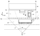
- FIG. 1 is a block diagram of a monitoring system according to an embodiment of the present invention. It is a plane schematic diagram of an example monitoring object field by the monitoring system concerning one embodiment of the present invention. It is a side surface schematic diagram of an example monitoring object field by the monitoring system concerning one embodiment of the present invention. It is a flowchart which shows the monitoring operation
- the monitoring system 1 of the present embodiment includes a laser radar 2 as a distance measuring device and a system computer 3.
- the system computer 3 includes an object detection unit 30, a monitoring area setting unit 31, a monitoring area abnormality detection unit 32, an abnormality transmission unit 33, an obstacle determination unit 34, and an obstacle information transmission unit 35.
- the obstacle determination unit 34 includes a feature amount calculation unit 34a and a determination unit 34b.
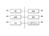
- the system computer 3 is a main computer of this monitoring system, and as shown in FIG. 5, a CPU (Central Processing Unit) 301, a RAM (Random Access Memory) 302, a ROM (Read Only Memory) 303, a hard disk drive (HDD). 304, a GUI (Graphical User Interface) 305, a network interface 306, and the like.
- a CPU Central Processing Unit
- RAM Random Access Memory
- ROM Read Only Memory
- HDD hard disk drive
- GUI Graphic User Interface
- the CPU 301 realizes a computer program, thereby realizing the above-described means 30-35 and a monitoring article setting means 36 described later.
- the GUI 305 includes an image display device 37 that displays an image to the user shown in FIG. 1 and an operation input device 38 that is used by the user, such as a mouse and a touch screen.
- an operation input device 38 that is used by the user, such as a mouse and a touch screen.
- the system computer 3 is provided integrally with the laser radar 2 or a plurality of computers.
- the laser radar 2 is installed facing the building 10 via a site 11 in front of the building 10 and a road 12 in front of the site 11.
- the two-axis coordinates in the vertical direction and the horizontal direction viewed from the laser radar 2 are set as XZ coordinates
- the coordinate axes perpendicular to the X-coordinate axes and the Z-coordinate axes are set as Y axes.
- the laser radar 2 scans the space as shown in FIGS.
- the user installs and adjusts the laser radar 2 so that the site 11 is within the horizontal scanning angle ⁇ and the vertical scanning angle ⁇ .
- the monitoring area setting means 31 displays a three-dimensional image based on the measurement distance data measured by the laser radar 2 in a situation where the user has confirmed the site in advance on the image display device 37 together with the reference XYZ coordinates, and monitors the user. Requests region settings.
- the user inputs an instruction to set a monitoring area to the system computer 3 by specifying an area with XYZ coordinates via the GUI (image display device 37 and operation input device 38).
- the monitoring area setting means 31 sets a predetermined monitoring area A1 in the area A measured by the laser radar 2 (S1).
- the space on the site 11 in the region A measured by the laser radar 2 is set as the monitoring region A1.
- a range where the X coordinate is from X0 to X1 and the Y coordinate is from Y0 to Y1 is designated as the monitoring area A1.
- the system computer 3 starts distance measurement to the laser radar 2. And the process shifts to the monitoring loop L1.
- the monitoring area abnormality detection means 32 detects the presence of an intruder (61) in the monitoring area A1 as an abnormality will be described.
- the measurement distance data is acquired for each frame and stored in the memory (S3), and the object detection unit 30 performs clustering of the object detection points based on the measurement distance data to detect the object (S4).
- the object detection method is not particularly limited, and any method such as background difference, two-frame difference, or the like can be used.
- the monitoring area abnormality detection means 32 determines whether or not the object detected in step S4 is in the monitoring area A1 (S5). If YES in step S5, the monitoring area abnormality detection means 32 proceeds to step S6 as an abnormality.
- the abnormality transmission unit 33 transmits the abnormality detected by the monitoring region abnormality detection unit 32. Information transmitted by the abnormality transmitter 33 is received by the information terminal 5 via the network interface 306, the alarm device 4, and further via the communication network 100. The received alarm device 4 displays an alarm notifying the abnormality.
- the information terminal 5 displays by voice information, characters and other visual information.
- the alarm device 4 Upon receipt, the alarm device 4 executes a predetermined ringing operation assigned to the intruder detection, and if there is a light emission function, also executes a light emission operation. It is preferable to automatically display the information terminal 5 immediately. For this purpose, it is preferable to perform automatic display using sound and images (a so-called pop-up display). In that case, it is preferable to display the contents of the intruder discovery by voice or / and text.
- the obstacle determination means 34 determines whether there is an obstacle (62) that hinders the measurement of the monitoring area A1 by a predetermined amount in the near area A2 between the monitoring area A1 and the laser radar 2. Is determined based on (obstacle determination routine R1).
- the obstacle determination routine R1 when the object detected in step S4 is in the front area A2, the obstacle determination means 34 first determines the feature amount of the object in the front area A2 by the feature amount calculation unit 34a.
- the determination unit 34b determines whether the object is an obstacle based on the feature amount obtained by the feature amount calculation unit. As an example, when there is an object in the near area A2 as shown in the flowchart of FIG.
- step S11 the process proceeds to step S12
- the feature amount calculation unit 34a calculates the size of the object from the three-dimensional point cloud information of the object.
- the height information (height (Z direction), width (X direction), depth (Y direction)) is obtained by calculation.
- the determination unit 34b determines that the object is an obstacle when it is larger than a person based on the information on the size of the object obtained by the feature amount calculation unit 34a (step S12). If YES in S12, Step S14). In other words, a predetermined threshold value for specifying an object larger than a person is set in advance, and object size information (height (Z direction), width (X direction), depth (Y direction)) is equal to or greater than the threshold value.
- the width or height is preferably used for determination. That is, the feature amount calculation unit 34a obtains the width or / and height of the object based on the three-dimensional measurement distance data as the object size information, and the determination unit 34b obtains the feature amount calculation unit 34a. When the width or / and height is equal to or greater than a predetermined threshold, it is determined as an obstacle. As an example of a method for determining whether or not the object is larger than the person, the maximum value among the height, width and depth of the object is obtained, and the determination is made based on whether or not the height is equal to or higher than the assumed height.
- the size of the person is taken as an example of the threshold value, the user arbitrarily sets the threshold value via the GUI (image display device 37 and operation input device 38).
- the obstacle information transmitting means 35 transmits that there is an obstacle (62) in the near area A2 when it is determined by the obstacle determination routine R1 that there is an obstacle (S7).
- the information transmitted by the obstacle information transmitting means 35 is received by the alarm terminal 4 via the network interface 306 and further to the information terminal 5 via the communication network 100.
- the received alarm device 4 displays an alarm notifying the presence of an obstacle.
- the information terminal 5 displays by voice information, characters and other visual information.
- the alarm device 4 executes an alarm having a distinctiveness to the alarm notifying the abnormality. For example, the distinctiveness is given by different ringing patterns.
- the alarm device 4 Upon receipt, the alarm device 4 executes a predetermined ringing operation assigned to obstacle detection, and if there is a light emission function, also executes a light emission operation. In the light emitting function, it is preferable to give the discriminability by the light emission color and the light emission pattern. It is preferable to automatically display the information terminal 5 immediately. For this purpose, it is preferable to perform automatic display using sound and images (a so-called pop-up display). In that case, it is preferable to display the contents of obstacle detection by voice or / and text. The information terminal 5 also executes a display having a distinctiveness with respect to the display notifying the abnormality in some form. For example, distinguishability is given by different audio patterns.
- the alarm device 4 and the information terminal 5 as described above notify the user that there is an obstacle (62).
- the size of the object is given as an example of the feature quantity obtained by the feature quantity computing unit 34a.
- the feature quantity obtained by the feature quantity computing unit 34a may be the shape of the object.
- Examples of the feature quantity indicating the shape of the object include rectangularity and moment feature quantity.
- Non-Patent Document 1 is helpful. By detecting an object from the three-dimensional measuring distance data and projecting the object onto a plane, the rectangularity can be calculated and the rectangularity can be used.
- the moment feature amount can also be used as a feature amount as a basis for determination when the shape feature of an obstacle such as a vehicle is known in advance.
- the monitoring system 1 is configured to monitor items in the monitoring area as shown in FIGS.
- the present invention can be applied to detecting the absence of (63) as an abnormality.
- the system computer 3 further includes monitoring article setting means 36 for presetting the monitoring target article installed in the monitoring area, and the monitoring article setting means 36 and the monitoring area abnormality detection means 32 are as follows. Function.
- the monitoring article setting means 36 is installed in the monitoring area A1 or A3 set by the monitoring area setting means 31, and the monitoring object article (designated by the user via the GUI (image display device 37 and operation input device 38)) ( 63) the clustered three-dimensional point cloud data is stored.
- the monitoring region abnormality detection means 32 determines that the stored point cloud data is abnormal when it is determined that the stored point cloud data has moved or is missing (point cloud data has disappeared). In other words, the monitoring area abnormality detection unit 32 detects that the monitoring target article is not present in the monitoring area and has moved within the monitoring area as an abnormality.
- the abnormality transmission means 33 transmits that the monitored object (63) has been lost / moved, and notifies the user through the alarm device 4 or the information terminal 5.
- the monitoring area abnormality detection means 32 may be implemented as detecting that the monitoring target article is not present in the monitoring area as an abnormality, for example, a pet or livestock in a fence or cage. It is effective for animal surveillance. As described above, according to the present monitoring system 1 that promotes the removal of obstacles, whether it is abnormal or not present in the monitoring area, the reliability of abnormality detection is improved.
- the fact that there is an obstacle (62) that hinders the measurement of the monitoring area (A1) by a predetermined amount between the monitoring area (A1) and the distance measuring device (2) is transmitted.
- the user can be encouraged to take action to remove the obstacle, obstruction removal is promoted, and the reliability of the monitoring system can be improved.
- the present invention can be used for a monitoring system.
- Monitoring system 2 Laser radar 3
- System computer 4 Alarm 5
- Information terminal 10 Building 11 Site 12 Road A1 Monitoring area A2 Front area ⁇ Horizontal scanning angle ⁇ Vertical scanning angle
Landscapes
- Physics & Mathematics (AREA)
- General Physics & Mathematics (AREA)
- Engineering & Computer Science (AREA)
- Computer Networks & Wireless Communication (AREA)
- Electromagnetism (AREA)
- Radar, Positioning & Navigation (AREA)
- Remote Sensing (AREA)
- Business, Economics & Management (AREA)
- Emergency Management (AREA)
- Optical Radar Systems And Details Thereof (AREA)
- Burglar Alarm Systems (AREA)
- Alarm Systems (AREA)
Abstract
監視を妨げる障害物への対策を施し、監視システムの信頼性を向上させる。監視システム(1)は、監視領域(A1)と距離測定装置(2)の間(A2)に監視領域の測定を所定量妨げる障害物(62)があるかどうかを距離測定装置の測定距離データに基づき判定する障害物判定手段(34)と、障害物判定手段により障害物があると判断された場合に、監視領域と距離測定装置の間に障害物がある旨を発信する障害物情報発信手段(35)とを備える。障害物判定手段は、測定距離データに基づき監視領域と距離測定装置の間に検出される物体の特徴量を求める特徴量演算部(34a)と、当該特徴量演算部により求められた特徴量に基づき当該物体が障害物であるかどうかを判断する判断部(34b)とを有する。
Description
本発明は、監視システムに関する。
近年、監視空間内の侵入者や車両を検出する目的で、レーザーレーダーなどで検出した距離画像の中から物体を検出する技術が様々な目的に利用されている。
特許文献1には、レーザーレーダーによる距離測定を用いた侵入者検知システムが提案されている。
侵入者検知システムにおける監視領域とは、侵入者がその領域内に侵入したかどうかを判定する領域のことをここでは示す。
監視領域とレーザーレーダーの間に監視を妨げる障害物が出現した場合、障害物の奥側の測定は不可能となり、本来実施すべき異常検知の性能が発揮できなくなるという課題がある。
上記を鑑みて、特許文献2や特許文献3のように、レーザーレーダーのカバー及びその近傍が覆われたことを検出する障害物の検知機能が提案されている。
特許文献1には、レーザーレーダーによる距離測定を用いた侵入者検知システムが提案されている。
侵入者検知システムにおける監視領域とは、侵入者がその領域内に侵入したかどうかを判定する領域のことをここでは示す。
監視領域とレーザーレーダーの間に監視を妨げる障害物が出現した場合、障害物の奥側の測定は不可能となり、本来実施すべき異常検知の性能が発揮できなくなるという課題がある。
上記を鑑みて、特許文献2や特許文献3のように、レーザーレーダーのカバー及びその近傍が覆われたことを検出する障害物の検知機能が提案されている。
P. L. Rosin: "Measuring rectangularity"https://users.cs.cf.ac.uk/Paul.Rosin/resources/papers/rectangularity-MVA-postprint.pdf
しかし、特許文献2,3のような従来技術では、レーザー光を出射する窓の近傍よりも離れた場所に障害物が発生した場合、(例えば、図X1のようにレーザーレーダーから離れた敷地を監視する際に、監視領域の手前に大型車が駐車してしまった場合など)が考慮されていない。
こういった場合においても侵入者を検知したい領域を監視することが不可能であり、なおかつそれは意図的、偶発的によらず人為的に設置されたものである場合が多く、その障害物を除くための行動へユーザー(監視員)を促す必要がある。
また、このような通知を行うことは早期であるほうが望ましい。その際は障害物が何であるか(人物、車など)判定することで、除去すべき対象かどうかをユーザーが判断することが容易になるということが期待できるが、この場合は高次の認識処理を要するため、解析処理の時間が増大してしまう。
こういった場合においても侵入者を検知したい領域を監視することが不可能であり、なおかつそれは意図的、偶発的によらず人為的に設置されたものである場合が多く、その障害物を除くための行動へユーザー(監視員)を促す必要がある。
また、このような通知を行うことは早期であるほうが望ましい。その際は障害物が何であるか(人物、車など)判定することで、除去すべき対象かどうかをユーザーが判断することが容易になるということが期待できるが、この場合は高次の認識処理を要するため、解析処理の時間が増大してしまう。
本発明は以上の従来技術における問題に鑑みてなされたものであって、監視を妨げる障害物への対策を施し、監視システムの信頼性を向上させることを課題とする。
以上の課題を解決するための請求項1記載の発明は、空間にある物体までの距離を測定し測定距離データを生成する距離測定装置を具備した監視システムにおいて、
前記距離測定装置が測定する領域内に所定の監視領域を設定する監視領域設定手段と、
前記測定距離データに基づき前記監視領域内の異常を検知する監視領域異常検知手段と、前記監視領域異常検知手段が検知した異常を発信する異常発信手段と、
前記監視領域と前記距離測定装置の間に前記監視領域の測定を所定量妨げる障害物があるかどうかを前記測定距離データに基づき判定する障害物判定手段と、
前記障害物判定手段により障害物があると判断された場合に、前記監視領域と前記距離測定装置の間に障害物がある旨を発信する障害物情報発信手段とを備え、
前記障害物判定手段は、前記測定距離データに基づき前記監視領域と前記距離測定装置の間に検出される物体の特徴量を求める特徴量演算部と、当該特徴量演算部により求められた特徴量に基づき当該物体が障害物であるかどうかを判断する判断部とを有する監視システムである。
前記距離測定装置が測定する領域内に所定の監視領域を設定する監視領域設定手段と、
前記測定距離データに基づき前記監視領域内の異常を検知する監視領域異常検知手段と、前記監視領域異常検知手段が検知した異常を発信する異常発信手段と、
前記監視領域と前記距離測定装置の間に前記監視領域の測定を所定量妨げる障害物があるかどうかを前記測定距離データに基づき判定する障害物判定手段と、
前記障害物判定手段により障害物があると判断された場合に、前記監視領域と前記距離測定装置の間に障害物がある旨を発信する障害物情報発信手段とを備え、
前記障害物判定手段は、前記測定距離データに基づき前記監視領域と前記距離測定装置の間に検出される物体の特徴量を求める特徴量演算部と、当該特徴量演算部により求められた特徴量に基づき当該物体が障害物であるかどうかを判断する判断部とを有する監視システムである。
請求項2記載の発明は、前記特徴量演算部で求められる特徴量は、物体の大きさ及び物体の形状のうち少なくとも一方の情報を含んでいる請求項1に記載の監視システムである。
請求項3記載の発明は、前記距離測定装置は、空間を2軸走査して3次元の測定距離データを生成し、
前記特徴量演算部は、前記物体の大きさの情報として、前記3次元の測定距離データに基づき前記監視領域と前記距離測定装置の間に検出される物体の幅及び高さのうちの少なくとも一方を求め、
前記判断部は、前記特徴量演算部が求めた前記大きさが所定の閾値以上である場合に障害物であると判断する請求項2に記載の監視システムである。
前記特徴量演算部は、前記物体の大きさの情報として、前記3次元の測定距離データに基づき前記監視領域と前記距離測定装置の間に検出される物体の幅及び高さのうちの少なくとも一方を求め、
前記判断部は、前記特徴量演算部が求めた前記大きさが所定の閾値以上である場合に障害物であると判断する請求項2に記載の監視システムである。
請求項4記載の発明は、前記距離測定装置は、空間を2軸走査して3次元の測定距離データを生成し、
前記特徴量演算部は、前記物体の形状の情報として、前記3次元の測定距離データに基づき前記監視領域と前記距離測定装置の間に検出される物体を平面に投影して矩形度を計算し、
前記判断部は、前記特徴量演算部が求めた前記矩形度が所定の閾値以上である場合に障害物であると判断する請求項2に記載の監視システムである。
前記特徴量演算部は、前記物体の形状の情報として、前記3次元の測定距離データに基づき前記監視領域と前記距離測定装置の間に検出される物体を平面に投影して矩形度を計算し、
前記判断部は、前記特徴量演算部が求めた前記矩形度が所定の閾値以上である場合に障害物であると判断する請求項2に記載の監視システムである。
請求項5記載の発明は、前記異常発信手段及び前記障害物情報発信手段からの情報を受信して警報を表示する警報機を備える請求項1から請求項4のうちいずれか一に記載の監視システムである。
請求項6記載の発明は、前記警報機は、前記異常発信手段からの情報と、前記障害物情報発信手段からの情報とで、識別性のある警報を実行する請求項5に記載の監視システムである。
請求項7記載の発明は、前記異常発信手段及び前記障害物情報発信手段からの情報を、通信ネットワークを介して受信し、音声情報、文字その他の視覚情報により表示する情報端末を備える請求項1から請求項5のうちいずれか一に記載の監視システムである。
請求項8記載の発明は、前記情報端末は、前記異常発信手段からの情報と、前記障害物情報発信手段からの情報とで、識別性のある表示を実行する請求項7に記載の監視システムである。
請求項9記載の発明は、前記監視領域異常検知手段は前記監視領域に侵入者が存在することを異常として検知する請求項1から請求項8のうちいずれか一に記載の監視システムである。
請求項10記載の発明は、前記監視領域内に設置されている監視対象物品を予め設定する監視物品設定手段を備え、
前記監視領域異常検知手段は、前記監視対象物品が前記監視領域に不存在であること及び前記監視領域内で移動したこと、又は前記監視対象物品が前記監視領域に不存在であることを異常として検知する請求項1から請求項8のうちいずれか一に記載の監視システムである。
前記監視領域異常検知手段は、前記監視対象物品が前記監視領域に不存在であること及び前記監視領域内で移動したこと、又は前記監視対象物品が前記監視領域に不存在であることを異常として検知する請求項1から請求項8のうちいずれか一に記載の監視システムである。
以上説明したように本発明によれば、監視領域と距離測定装置の間に監視領域の測定を所定量妨げる障害物がある旨を発信することで、その障害物を除くための行動へユーザー(監視員)を促すことができ、障害物除去が促進され監視システムの信頼性を向上させることができる。
以下に本発明の一実施形態につき図面を参照して説明する。以下は本発明の一実施形態であって本発明を限定するものではない。
図1に示すように本実施形態の監視システム1は、距離測定装置としてのレーザーレーダー2と、システム・コンピューター3とを備える。
システム・コンピューター3は、物体検出手段30と、監視領域設定手段31と、監視領域異常検知手段32と、異常発信手段33と、障害物判定手段34と、障害物情報発信手段35とを備える。
障害物判定手段34は、特徴量演算部34aと、判断部34bとを有する。
システム・コンピューター3は、本監視システムのメインコンピューターであり、図5に示すようにCPU(Central Processing Unit)301、RAM(Random Access Memory)302、ROM(Read Only Memory)303、ハードディスクドライブ(HDD)304、GUI(Graphical User Interface)305、ネットワークインターフェース306等を備え、CPU301がコンピュータープログラムを実現することで、上掲の手段30‐35及び後述の監視物品設定手段36を実現するものである。GUI305には、図1に示すユーザーへ画像を表示する画像表示装置37、マウス、タッチスクリーンなどのユーザーの利用に供される操作入力装置38が含まれる。
システム・コンピューター3がレーザーレーダー2と一体に設けられているとか、複数台のコンピューターにより構成されているとかのハードウエア構成は問わない。
システム・コンピューター3は、物体検出手段30と、監視領域設定手段31と、監視領域異常検知手段32と、異常発信手段33と、障害物判定手段34と、障害物情報発信手段35とを備える。
障害物判定手段34は、特徴量演算部34aと、判断部34bとを有する。
システム・コンピューター3は、本監視システムのメインコンピューターであり、図5に示すようにCPU(Central Processing Unit)301、RAM(Random Access Memory)302、ROM(Read Only Memory)303、ハードディスクドライブ(HDD)304、GUI(Graphical User Interface)305、ネットワークインターフェース306等を備え、CPU301がコンピュータープログラムを実現することで、上掲の手段30‐35及び後述の監視物品設定手段36を実現するものである。GUI305には、図1に示すユーザーへ画像を表示する画像表示装置37、マウス、タッチスクリーンなどのユーザーの利用に供される操作入力装置38が含まれる。
システム・コンピューター3がレーザーレーダー2と一体に設けられているとか、複数台のコンピューターにより構成されているとかのハードウエア構成は問わない。
以上の構成の監視システムにより図2A,2Bに示すような現場を監視する場合を例として説明する。
図2A,2Bにおいてレーザーレーダー2は、建物10の手前の敷地11、さらに敷地11の手前の道路12を介して建物10に対面して設置されている。
レーザーレーダー2から見た垂直方向及び水平方向の2軸座標をXZ座標とし、X座標軸及びZ座標軸に垂直な座標軸をY軸として、図2A,2B中に示す。
レーザーレーダー2は、図2A,2Bに示すような空間をX軸及びZ軸方向に2軸走査して3次元の測定距離データを生成し、システム・コンピューター3に出力する。
予め、ユーザーがレーザーレーダー2を敷地11が水平走査角α及び垂直走査角β内に収まるように設置し調整する。
図2A,2Bにおいてレーザーレーダー2は、建物10の手前の敷地11、さらに敷地11の手前の道路12を介して建物10に対面して設置されている。
レーザーレーダー2から見た垂直方向及び水平方向の2軸座標をXZ座標とし、X座標軸及びZ座標軸に垂直な座標軸をY軸として、図2A,2B中に示す。
レーザーレーダー2は、図2A,2Bに示すような空間をX軸及びZ軸方向に2軸走査して3次元の測定距離データを生成し、システム・コンピューター3に出力する。
予め、ユーザーがレーザーレーダー2を敷地11が水平走査角α及び垂直走査角β内に収まるように設置し調整する。
図1及び図2A,2Bに加え図3のフローチャートを参照して本監視システムの動作につき説明する。
監視領域設定手段31は、予めユーザーが現場を確認した状況でレーザーレーダー2が測定した測定距離データに基づく3次元画像を、基準となるXYZ座標とともに画像表示装置37に表示し、ユーザーに対し監視領域の設定を要求する。ユーザーは、監視領域を設定する指示を、GUI(画像表示装置37及び操作入力装置38)を介してXYZ座標による領域指定によりシステム・コンピューター3に入力する。
監視領域設定手段31がこれに応じて、レーザーレーダー2が測定する領域A内に所定の監視領域A1を設定する(S1)。ここでは、レーザーレーダー2が測定する領域Aの内、敷地11上の空間が監視領域A1に設定されたとする。図2Aに示すように、X座標がX0からX1まで、Y座標がY0からY1までの範囲が監視領域A1として指定される。
監視領域設定手段31は、予めユーザーが現場を確認した状況でレーザーレーダー2が測定した測定距離データに基づく3次元画像を、基準となるXYZ座標とともに画像表示装置37に表示し、ユーザーに対し監視領域の設定を要求する。ユーザーは、監視領域を設定する指示を、GUI(画像表示装置37及び操作入力装置38)を介してXYZ座標による領域指定によりシステム・コンピューター3に入力する。
監視領域設定手段31がこれに応じて、レーザーレーダー2が測定する領域A内に所定の監視領域A1を設定する(S1)。ここでは、レーザーレーダー2が測定する領域Aの内、敷地11上の空間が監視領域A1に設定されたとする。図2Aに示すように、X座標がX0からX1まで、Y座標がY0からY1までの範囲が監視領域A1として指定される。
次に、ユーザーからGUI(画像表示装置37及び操作入力装置38)を介して監視を開始する指示がシステム・コンピューター3に入力されると、システム・コンピューター3は、レーザーレーダー2に距離測定の開始を指示するとともに、処理を監視ループL1に移行する。ここでは、監視領域異常検知手段32は監視領域A1に侵入者(61)が存在することを異常として検知する場合につき説明する。レーザーレーダー2は、システム・コンピューター3からの指示により距離測定を開始すると、領域A一面の距離測定データ(=1フレームの距離画像)を、一定のフレームレート(例えば、10fps, 24fps)で生成する。
監視ループL1では、フレーム毎に測定距離データを取得してメモリ上に保持し(S3)、物体検出手段30が測定距離データに基づき物体検出点のクラスタリングを行って物体を検出する(S4)。ここで、侵入者を検知する目的であるので、明らかに人物でない物体を排除して物体を検出する処理を入れてもよい。なお、物体検出方法は、特に限定されるものではなく、背景差分、2フレーム差分等の方法を問わない。
監視ループL1では、フレーム毎に測定距離データを取得してメモリ上に保持し(S3)、物体検出手段30が測定距離データに基づき物体検出点のクラスタリングを行って物体を検出する(S4)。ここで、侵入者を検知する目的であるので、明らかに人物でない物体を排除して物体を検出する処理を入れてもよい。なお、物体検出方法は、特に限定されるものではなく、背景差分、2フレーム差分等の方法を問わない。
次に、監視領域異常検知手段32は、ステップS4で検出した物体が監視領域A1内の在るかを判断し(S5)、ステップS5でYESの場合は異常としてステップS6に移行する。
ステップS6で異常発信手段33は、監視領域異常検知手段32が検知した異常を発信する。異常発信手段33が発信する情報はネットワークインターフェース306を介して、警報機4や、さらに通信ネットワーク100を介して情報端末5に受信される。受信した警報機4は、異常を知らせる警報を表示する。情報端末5は、音声情報、文字その他の視覚情報により表示する。警報機4は、受信したら即座に侵入者発見に割り当てられた所定の鳴動動作を実行し、発光機能が有れば発光動作も実行する。情報端末5においても即座に自動表示することが好ましい。それには、音声及び画像による自動表示(いわゆるポップアップ表示と呼ばれる表示形態)を行うことが好ましい。その場合、音声又は/及び文字により侵入者発見の内容を表示することが好ましい。
ステップS6で異常発信手段33は、監視領域異常検知手段32が検知した異常を発信する。異常発信手段33が発信する情報はネットワークインターフェース306を介して、警報機4や、さらに通信ネットワーク100を介して情報端末5に受信される。受信した警報機4は、異常を知らせる警報を表示する。情報端末5は、音声情報、文字その他の視覚情報により表示する。警報機4は、受信したら即座に侵入者発見に割り当てられた所定の鳴動動作を実行し、発光機能が有れば発光動作も実行する。情報端末5においても即座に自動表示することが好ましい。それには、音声及び画像による自動表示(いわゆるポップアップ表示と呼ばれる表示形態)を行うことが好ましい。その場合、音声又は/及び文字により侵入者発見の内容を表示することが好ましい。
ステップS5でNOの場合は、障害物判定手段34は、監視領域A1とレーザーレーダー2の間の手前領域A2に監視領域A1の測定を所定量妨げる障害物(62)があるかどうかを測定距離データに基づき判定する(障害物判定ルーティンR1)。
障害物判定ルーティンR1では、障害物判定手段34はステップS4で検出した物体が手前領域A2に在る場合には、まず、特徴量演算部34aが手前領域A2に在るその物体の特徴量を求め、判断部34bが特徴量演算部により求められた特徴量に基づき当該物体が障害物であるかどうかを判断する。
一例として図4のフローチャートに示すように手前領域A2に物体がある場合(ステップS11でYESによりステップS12に移行)、特徴量演算部34aでは、同物体の3次元点群情報から同物体の大きさの情報(高さ(Z方向)、幅(X方向)、奥行き(Y方向))を演算により求める。ステップS12において、判断部34bは、特徴量演算部34aにより求められた物体の大きさの情報に基づき、それが人物よりも大きいものである場合に同物体が障害物であると判断する(ステップS12でYESによりステップS14)。すなわち、人物よりも大きいものを特定する所定の閾値を予め設定しておき、物体の大きさの情報(高さ(Z方向)、幅(X方向)、奥行き(Y方向))が同閾値以上である場合に、障害物であると判断する。高さ(Z方向)、幅(X方向)、奥行き(Y方向)の3情報のうち、幅又は高さは判断に用いることが好ましい。すなわち、特徴量演算部34aは、物体の大きさの情報として、3次元の測定距離データに基づき、物体の幅又は/及び高さを求め、判断部34bは、特徴量演算部34aが求めた幅又は/及び高さが所定の閾値以上である場合に障害物であると判断する。
人物よりも大きいかどうかの判定方法の例として、物体の高さ、幅及び奥行きのうちの最大値を求め、それが想定した身長以上であるかどうかで判断する。例えば2.0m以上とした場合には次式で表される。
if( Max(Height,Width,Depth)>2.0) then {return TRUE}
else {return FALSE}
(関数や変数の説明)
Max()・・・最大値を返す関数
Height,Width,Depth・・・それぞれ高さ、幅、奥行き(単位:m)、
TRUE:障害物である、FALSE:障害物ではない
障害物判定ルーティンR1では、障害物判定手段34はステップS4で検出した物体が手前領域A2に在る場合には、まず、特徴量演算部34aが手前領域A2に在るその物体の特徴量を求め、判断部34bが特徴量演算部により求められた特徴量に基づき当該物体が障害物であるかどうかを判断する。
一例として図4のフローチャートに示すように手前領域A2に物体がある場合(ステップS11でYESによりステップS12に移行)、特徴量演算部34aでは、同物体の3次元点群情報から同物体の大きさの情報(高さ(Z方向)、幅(X方向)、奥行き(Y方向))を演算により求める。ステップS12において、判断部34bは、特徴量演算部34aにより求められた物体の大きさの情報に基づき、それが人物よりも大きいものである場合に同物体が障害物であると判断する(ステップS12でYESによりステップS14)。すなわち、人物よりも大きいものを特定する所定の閾値を予め設定しておき、物体の大きさの情報(高さ(Z方向)、幅(X方向)、奥行き(Y方向))が同閾値以上である場合に、障害物であると判断する。高さ(Z方向)、幅(X方向)、奥行き(Y方向)の3情報のうち、幅又は高さは判断に用いることが好ましい。すなわち、特徴量演算部34aは、物体の大きさの情報として、3次元の測定距離データに基づき、物体の幅又は/及び高さを求め、判断部34bは、特徴量演算部34aが求めた幅又は/及び高さが所定の閾値以上である場合に障害物であると判断する。
人物よりも大きいかどうかの判定方法の例として、物体の高さ、幅及び奥行きのうちの最大値を求め、それが想定した身長以上であるかどうかで判断する。例えば2.0m以上とした場合には次式で表される。
if( Max(Height,Width,Depth)>2.0) then {return TRUE}
else {return FALSE}
(関数や変数の説明)
Max()・・・最大値を返す関数
Height,Width,Depth・・・それぞれ高さ、幅、奥行き(単位:m)、
TRUE:障害物である、FALSE:障害物ではない
以上により、例えば図2A,2Bに示す車両62の幅(X方向寸法)が閾値を超えて車両62が障害物であると判断される。ステップS11でNOの場合及びステップS12でNOの場合は、障害物なしと判断する。
上記の閾値として人物の大きさを例に挙げたが、閾値については、ユーザーがGUI(画像表示装置37及び操作入力装置38)を介して任意に設定する。
上記の閾値として人物の大きさを例に挙げたが、閾値については、ユーザーがGUI(画像表示装置37及び操作入力装置38)を介して任意に設定する。
障害物情報発信手段35は、障害物判定ルーティンR1にて障害物があると判定された場合に、手前領域A2に障害物(62)がある旨を発信する(S7)。ここでも、障害物情報発信手段35が発信する情報はネットワークインターフェース306を介して、警報機4や、さらに通信ネットワーク100を介して情報端末5に受信される。受信した警報機4は、障害物の存在を知らせる警報を表示する。情報端末5は、音声情報、文字その他の視覚情報により表示する。その際、警報機4は、上記の異常を知らせる警報に対して識別性のある警報を実行する。例えば、鳴動パターンが異なることによって識別性を与える。警報機4は、受信したら即座に障害物発見に割り当てられた所定の鳴動動作を実行し、発光機能が有れば発光動作も実行する。発光機能においては、発光色、発光パターンにより上記識別性を与えることが好ましい。
情報端末5においても即座に自動表示することが好ましい。それには、音声及び画像による自動表示(いわゆるポップアップ表示と呼ばれる表示形態)を行うことが好ましい。その場合、音声又は/及び文字により障害物発見の内容を表示することが好ましい。情報端末5でも、なんらかの形態で、上記の異常を知らせる表示に対して識別性のある表示を実行する。例えば、音声パターンが異なることによって識別性を与える。
情報端末5としてのPCやタブレット端末上を見ているユーザーに侵入者発見なのか、障害物発見なのかを通知させるためであり、さらに具体的には、音声(アラーム音)、文字(メールやSNSによる通知、プッシュ通知等)、映像(PopUpで異常を知らせる表示ウィンドウが立ち上がる形態、他のウィンドウとは異なる色にして問題を通知する形態等)による方法が挙げられる。
侵入者発見を障害物発見に比較して緊急性の高い表示形態に設定することが好ましい。
以上のようにした警報機4や、情報端末5により、障害物(62)があることをユーザーに通知する。
情報端末5においても即座に自動表示することが好ましい。それには、音声及び画像による自動表示(いわゆるポップアップ表示と呼ばれる表示形態)を行うことが好ましい。その場合、音声又は/及び文字により障害物発見の内容を表示することが好ましい。情報端末5でも、なんらかの形態で、上記の異常を知らせる表示に対して識別性のある表示を実行する。例えば、音声パターンが異なることによって識別性を与える。
情報端末5としてのPCやタブレット端末上を見ているユーザーに侵入者発見なのか、障害物発見なのかを通知させるためであり、さらに具体的には、音声(アラーム音)、文字(メールやSNSによる通知、プッシュ通知等)、映像(PopUpで異常を知らせる表示ウィンドウが立ち上がる形態、他のウィンドウとは異なる色にして問題を通知する形態等)による方法が挙げられる。
侵入者発見を障害物発見に比較して緊急性の高い表示形態に設定することが好ましい。
以上のようにした警報機4や、情報端末5により、障害物(62)があることをユーザーに通知する。
(変形例)
以上の実施形態に対する変形例につき説明する。
上記実施形態にあっては、特徴量演算部34aが求める特徴量の例として物体の大きさを挙げたが、特徴量演算部34aが求める特徴量を物体の形状としてもよい。物体の形状を指標する特徴量の例としては、矩形度、モーメント特徴量を挙げることができる。矩形度が高いほど自然物より人工物に近いと推定できる
矩形度で障害物判定を行う場合、ステップS12を次のように置き換える。すなわち、特徴量演算部34aは、ステップS4で検出した物体を平面に投影した平面図形とし、この平面図形の矩形度を求める。投影する平面を、X-Z平面等の予め設定した一平面とする方法がある。その他には、異なる複数の角度の平面に投影してそれぞれ矩形度を計算し、最も高い矩形度を用いて判断する方法がある。自然物は、どの角度から見ても矩形度が低いからである。
判断部34bは、矩形度が所定の閾値以上に高いか否か判断し、高いと判斷した場合は、人工物と推定することができ、障害物であると判断する。矩形度の計算に関しては、非特許文献1が参考になる。3次元の測瑛距離データから物体を検出し、その物体を平面に投影することで、矩形度を計算でき、矩形度を利用することができる。
モーメント特徴量についても、車両など障害物の形状的特徴が予めわかっている場合などに判断の基礎とする特徴量として使用することも可能である。
以上の実施形態に対する変形例につき説明する。
上記実施形態にあっては、特徴量演算部34aが求める特徴量の例として物体の大きさを挙げたが、特徴量演算部34aが求める特徴量を物体の形状としてもよい。物体の形状を指標する特徴量の例としては、矩形度、モーメント特徴量を挙げることができる。矩形度が高いほど自然物より人工物に近いと推定できる
矩形度で障害物判定を行う場合、ステップS12を次のように置き換える。すなわち、特徴量演算部34aは、ステップS4で検出した物体を平面に投影した平面図形とし、この平面図形の矩形度を求める。投影する平面を、X-Z平面等の予め設定した一平面とする方法がある。その他には、異なる複数の角度の平面に投影してそれぞれ矩形度を計算し、最も高い矩形度を用いて判断する方法がある。自然物は、どの角度から見ても矩形度が低いからである。
判断部34bは、矩形度が所定の閾値以上に高いか否か判断し、高いと判斷した場合は、人工物と推定することができ、障害物であると判断する。矩形度の計算に関しては、非特許文献1が参考になる。3次元の測瑛距離データから物体を検出し、その物体を平面に投影することで、矩形度を計算でき、矩形度を利用することができる。
モーメント特徴量についても、車両など障害物の形状的特徴が予めわかっている場合などに判断の基礎とする特徴量として使用することも可能である。
上記実施形態では、監視領域A1に侵入者(61)が存在することを異常として検知する場合を取り扱ったが、本監視システム1は、例えば図2A,2Bに示すように監視領域に監視対象物品(63)が不存在であることを異常として検知することに応用することができる。この場合、システム・コンピューター3は、監視領域内に設置されている監視対象物品を予め設定する監視物品設定手段36をさらに備え、監視物品設定手段36及び監視領域異常検知手段32は以下のように機能する。
まず、監視物品設定手段36は、監視領域設定手段31が設定した監視領域A1又はA3に設置され、ユーザーからGUI(画像表示装置37及び操作入力装置38)を介して指定された監視対象物品(63)のクラスタリングされた3次元の点群データを記憶する。
監視領域異常検知手段32は、記憶された点群データが移動もしくは、欠如した(点群データが消えた)と判断した時に異常と判断する。すなわち、監視領域異常検知手段32は、監視対象物品が監視領域に不存在であること及び監視領域内で移動したことを異常として検知する。
異常と判断されれば、監視対象物品(63)が紛失した/移動したことを異常発信手段33が発信し、警報機4や、情報端末5を通じてユーザーに通知する。
なお、監視領域異常検知手段32が、監視対象物品が監視領域に不存在であることのみを異常として検知することとしても実施してもよい、例えば、柵又は檻の中のペットや家畜などの動物監視に有効である。
以上のように、監視領域に在ることが異常の場合も、無いことが異常の場合も、障害物除去を促進する本監視システム1によれば、異常検出の信頼性が向上する。
まず、監視物品設定手段36は、監視領域設定手段31が設定した監視領域A1又はA3に設置され、ユーザーからGUI(画像表示装置37及び操作入力装置38)を介して指定された監視対象物品(63)のクラスタリングされた3次元の点群データを記憶する。
監視領域異常検知手段32は、記憶された点群データが移動もしくは、欠如した(点群データが消えた)と判断した時に異常と判断する。すなわち、監視領域異常検知手段32は、監視対象物品が監視領域に不存在であること及び監視領域内で移動したことを異常として検知する。
異常と判断されれば、監視対象物品(63)が紛失した/移動したことを異常発信手段33が発信し、警報機4や、情報端末5を通じてユーザーに通知する。
なお、監視領域異常検知手段32が、監視対象物品が監視領域に不存在であることのみを異常として検知することとしても実施してもよい、例えば、柵又は檻の中のペットや家畜などの動物監視に有効である。
以上のように、監視領域に在ることが異常の場合も、無いことが異常の場合も、障害物除去を促進する本監視システム1によれば、異常検出の信頼性が向上する。
以上説明したように本監視システム1によれば、監視領域(A1)と距離測定装置(2)の間に監視領域(A1)の測定を所定量妨げる障害物(62)がある旨を発信することで、その障害物を除くための行動へユーザー(監視員)を促すことができ、障害物除去が促進され監視システムの信頼性を向上させることができる。
本発明は、監視システムに利用することができる。
1 監視システム
2 レーザーレーダー
3 システム・コンピューター
4 警報機
5 情報端末
10 建物
11 敷地
12 道路
A1 監視領域
A2 手前領域
α 水平走査角
β 垂直走査角
2 レーザーレーダー
3 システム・コンピューター
4 警報機
5 情報端末
10 建物
11 敷地
12 道路
A1 監視領域
A2 手前領域
α 水平走査角
β 垂直走査角
Claims (10)
- 空間にある物体までの距離を測定し測定距離データを生成する距離測定装置を具備した監視システムにおいて、
前記距離測定装置が測定する領域内に所定の監視領域を設定する監視領域設定手段と、
前記測定距離データに基づき前記監視領域内の異常を検知する監視領域異常検知手段と、前記監視領域異常検知手段が検知した異常を発信する異常発信手段と、
前記監視領域と前記距離測定装置の間に前記監視領域の測定を所定量妨げる障害物があるかどうかを前記測定距離データに基づき判定する障害物判定手段と、
前記障害物判定手段により障害物があると判断された場合に、前記監視領域と前記距離測定装置の間に障害物がある旨を発信する障害物情報発信手段とを備え、
前記障害物判定手段は、前記測定距離データに基づき前記監視領域と前記距離測定装置の間に検出される物体の特徴量を求める特徴量演算部と、当該特徴量演算部により求められた特徴量に基づき当該物体が障害物であるかどうかを判断する判断部とを有する監視システム。 - 前記特徴量演算部で求められる特徴量は、物体の大きさ及び物体の形状のうち少なくとも一方の情報を含んでいる請求項1に記載の監視システム。
- 前記距離測定装置は、空間を2軸走査して3次元の測定距離データを生成し、
前記特徴量演算部は、前記物体の大きさの情報として、前記3次元の測定距離データに基づき前記監視領域と前記距離測定装置の間に検出される物体の幅及び高さのうちの少なくとも一方を求め、
前記判断部は、前記特徴量演算部が求めた前記大きさが所定の閾値以上である場合に障害物であると判断する請求項2に記載の監視システム。 - 前記距離測定装置は、空間を2軸走査して3次元の測定距離データを生成し、
前記特徴量演算部は、前記物体の形状の情報として、前記3次元の測定距離データに基づき前記監視領域と前記距離測定装置の間に検出される物体を平面に投影して矩形度を計算し、
前記判断部は、前記特徴量演算部が求めた前記矩形度が所定の閾値以上である場合に障害物であると判断する請求項2に記載の監視システム。 - 前記異常発信手段及び前記障害物情報発信手段からの情報を受信して警報を表示する警報機を備える請求項1から請求項4のうちいずれか一に記載の監視システム。
- 前記警報機は、前記異常発信手段からの情報と、前記障害物情報発信手段からの情報とで、識別性のある警報を実行する請求項5に記載の監視システム。
- 前記異常発信手段及び前記障害物情報発信手段からの情報を、通信ネットワークを介して受信し、音声情報、文字その他の視覚情報により表示する情報端末を備える請求項1から請求項5のうちいずれか一に記載の監視システム。
- 前記情報端末は、前記異常発信手段からの情報と、前記障害物情報発信手段からの情報とで、識別性のある表示を実行する請求項7に記載の監視システム。
- 前記監視領域異常検知手段は前記監視領域に侵入者が存在することを異常として検知する請求項1から請求項8のうちいずれか一に記載の監視システム。
- 前記監視領域内に設置されている監視対象物品を予め設定する監視物品設定手段を備え、
前記監視領域異常検知手段は、前記監視対象物品が前記監視領域に不存在であること及び前記監視領域内で移動したこと、又は前記監視対象物品が前記監視領域に不存在であることを異常として検知する請求項1から請求項8のうちいずれか一に記載の監視システム。
Applications Claiming Priority (2)
| Application Number | Priority Date | Filing Date | Title |
|---|---|---|---|
| JP2017077912A JP2020101365A (ja) | 2017-04-11 | 2017-04-11 | 監視システム |
| JP2017-077912 | 2017-04-11 |
Publications (1)
| Publication Number | Publication Date |
|---|---|
| WO2018190252A1 true WO2018190252A1 (ja) | 2018-10-18 |
Family
ID=63792682
Family Applications (1)
| Application Number | Title | Priority Date | Filing Date |
|---|---|---|---|
| PCT/JP2018/014668 Ceased WO2018190252A1 (ja) | 2017-04-11 | 2018-04-06 | 監視システム |
Country Status (2)
| Country | Link |
|---|---|
| JP (1) | JP2020101365A (ja) |
| WO (1) | WO2018190252A1 (ja) |
Cited By (1)
| Publication number | Priority date | Publication date | Assignee | Title |
|---|---|---|---|---|
| US11776143B2 (en) | 2019-03-28 | 2023-10-03 | Nec Corporation | Foreign matter detection device, foreign matter detection method, and program |
Families Citing this family (1)
| Publication number | Priority date | Publication date | Assignee | Title |
|---|---|---|---|---|
| JP7664625B2 (ja) * | 2021-06-08 | 2025-04-18 | 北陽電機株式会社 | 検知エリア設定装置、支障物検出システムおよび検知エリア設定方法 |
Citations (5)
| Publication number | Priority date | Publication date | Assignee | Title |
|---|---|---|---|---|
| JP2007013709A (ja) * | 2005-06-30 | 2007-01-18 | Secom Co Ltd | 設定装置 |
| JP2007204003A (ja) * | 2006-02-06 | 2007-08-16 | Hokuyo Automatic Co | プラットホームドアの安全装置 |
| JP2011016421A (ja) * | 2009-07-08 | 2011-01-27 | Higashi Nippon Transportec Kk | 支障物検知装置及びこれを備えたプラットホームドアシステム並びに支障物検知方法 |
| US20150035694A1 (en) * | 2013-08-01 | 2015-02-05 | Robert Bosch Gmbh | Object determination using a radar sensor |
| JP2016099945A (ja) * | 2014-11-26 | 2016-05-30 | 日本電気株式会社 | 車両検知システム、画像処理サーバ及び車両検知方法 |
-
2017
- 2017-04-11 JP JP2017077912A patent/JP2020101365A/ja active Pending
-
2018
- 2018-04-06 WO PCT/JP2018/014668 patent/WO2018190252A1/ja not_active Ceased
Patent Citations (5)
| Publication number | Priority date | Publication date | Assignee | Title |
|---|---|---|---|---|
| JP2007013709A (ja) * | 2005-06-30 | 2007-01-18 | Secom Co Ltd | 設定装置 |
| JP2007204003A (ja) * | 2006-02-06 | 2007-08-16 | Hokuyo Automatic Co | プラットホームドアの安全装置 |
| JP2011016421A (ja) * | 2009-07-08 | 2011-01-27 | Higashi Nippon Transportec Kk | 支障物検知装置及びこれを備えたプラットホームドアシステム並びに支障物検知方法 |
| US20150035694A1 (en) * | 2013-08-01 | 2015-02-05 | Robert Bosch Gmbh | Object determination using a radar sensor |
| JP2016099945A (ja) * | 2014-11-26 | 2016-05-30 | 日本電気株式会社 | 車両検知システム、画像処理サーバ及び車両検知方法 |
Cited By (1)
| Publication number | Priority date | Publication date | Assignee | Title |
|---|---|---|---|---|
| US11776143B2 (en) | 2019-03-28 | 2023-10-03 | Nec Corporation | Foreign matter detection device, foreign matter detection method, and program |
Also Published As
| Publication number | Publication date |
|---|---|
| JP2020101365A (ja) | 2020-07-02 |
Similar Documents
| Publication | Publication Date | Title |
|---|---|---|
| EP3867889B1 (en) | Perimeter breach warning system | |
| JP6551512B2 (ja) | 監視システム、監視制御装置、監視方法、およびプログラム | |
| US9053621B2 (en) | Image surveillance system and image surveillance method | |
| KR102270401B1 (ko) | 스마트폰을 소지한 산만한 보행자를 위한 실시간 경고 | |
| US12207019B2 (en) | Monitoring system, monitoring method, and monitoring program | |
| EP3002741A1 (en) | Method and system for security system tampering detection | |
| CN111724558B (zh) | 一种监控方法、装置及入侵报警系统 | |
| TW201539385A (zh) | 利用方向感應之侵入偵測技術 | |
| JPWO2014002534A1 (ja) | 対象物認識装置 | |
| US12181603B2 (en) | Method and apparatus for high-confidence people classification, change detection, and nuisance alarm rejection based on shape classifier using 3D point cloud data | |
| KR101454644B1 (ko) | 보행자 추적기를 이용한 서성거림을 탐지하는 방법 | |
| WO2018190252A1 (ja) | 監視システム | |
| WO2015186395A1 (ja) | 車両周辺監視装置 | |
| EP3147864A2 (en) | Position estimating device and position estimating method | |
| CN108111802B (zh) | 视频监控方法及装置 | |
| JP2012212407A (ja) | 状態判定装置、状態判定方法およびプログラム | |
| WO2019031051A1 (ja) | 解析装置、監視システム及びプログラム | |
| CN111693986A (zh) | 一种目标对象入侵检测系统 | |
| CN117985053B (zh) | 感知能力检测方法及装置 | |
| WO2016147704A1 (ja) | 監視装置、監視システム、監視方法、及びコンピュータ読み取り可能な記録媒体 | |
| CN112520606A (zh) | 塔吊监控系统和塔吊监控方法 | |
| KR102407202B1 (ko) | 지능형 영상 분석 장치 및 방법 | |
| KR102935238B1 (ko) | 외곽 보안을 위한 장치, 시스템 및 방법 | |
| JP7815533B1 (ja) | システム、方法及びプログラム | |
| Lee et al. | DeepMonitor: A comprehensive approach for real‐time hazard detection for industrial safety |
Legal Events
| Date | Code | Title | Description |
|---|---|---|---|
| 121 | Ep: the epo has been informed by wipo that ep was designated in this application |
Ref document number: 18784932 Country of ref document: EP Kind code of ref document: A1 |
|
| NENP | Non-entry into the national phase |
Ref country code: DE |
|
| 122 | Ep: pct application non-entry in european phase |
Ref document number: 18784932 Country of ref document: EP Kind code of ref document: A1 |
|
| NENP | Non-entry into the national phase |
Ref country code: JP |