WO2018180904A1 - 運転保守管理方法、プログラム、及び運転保守管理システム - Google Patents
運転保守管理方法、プログラム、及び運転保守管理システム Download PDFInfo
- Publication number
- WO2018180904A1 WO2018180904A1 PCT/JP2018/011459 JP2018011459W WO2018180904A1 WO 2018180904 A1 WO2018180904 A1 WO 2018180904A1 JP 2018011459 W JP2018011459 W JP 2018011459W WO 2018180904 A1 WO2018180904 A1 WO 2018180904A1
- Authority
- WO
- WIPO (PCT)
- Prior art keywords
- information
- maintenance management
- scenario
- integrated system
- prediction
- Prior art date
- Legal status (The legal status is an assumption and is not a legal conclusion. Google has not performed a legal analysis and makes no representation as to the accuracy of the status listed.)
- Ceased
Links
Images

Classifications
-
- G—PHYSICS
- G06—COMPUTING OR CALCULATING; COUNTING
- G06Q—INFORMATION AND COMMUNICATION TECHNOLOGY [ICT] SPECIALLY ADAPTED FOR ADMINISTRATIVE, COMMERCIAL, FINANCIAL, MANAGERIAL OR SUPERVISORY PURPOSES; SYSTEMS OR METHODS SPECIALLY ADAPTED FOR ADMINISTRATIVE, COMMERCIAL, FINANCIAL, MANAGERIAL OR SUPERVISORY PURPOSES, NOT OTHERWISE PROVIDED FOR
- G06Q10/00—Administration; Management
- G06Q10/20—Administration of product repair or maintenance
-
- G—PHYSICS
- G05—CONTROLLING; REGULATING
- G05B—CONTROL OR REGULATING SYSTEMS IN GENERAL; FUNCTIONAL ELEMENTS OF SUCH SYSTEMS; MONITORING OR TESTING ARRANGEMENTS FOR SUCH SYSTEMS OR ELEMENTS
- G05B23/00—Testing or monitoring of control systems or parts thereof
- G05B23/02—Electric testing or monitoring
- G05B23/0205—Electric testing or monitoring by means of a monitoring system capable of detecting and responding to faults
- G05B23/0259—Electric testing or monitoring by means of a monitoring system capable of detecting and responding to faults characterized by the response to fault detection
- G05B23/0283—Predictive maintenance, e.g. involving the monitoring of a system and, based on the monitoring results, taking decisions on the maintenance schedule of the monitored system; Estimating remaining useful life [RUL]
-
- F—MECHANICAL ENGINEERING; LIGHTING; HEATING; WEAPONS; BLASTING
- F02—COMBUSTION ENGINES; HOT-GAS OR COMBUSTION-PRODUCT ENGINE PLANTS
- F02C—GAS-TURBINE PLANTS; AIR INTAKES FOR JET-PROPULSION PLANTS; CONTROLLING FUEL SUPPLY IN AIR-BREATHING JET-PROPULSION PLANTS
- F02C9/00—Controlling gas-turbine plants; Controlling fuel supply in air- breathing jet-propulsion plants
-
- G—PHYSICS
- G06—COMPUTING OR CALCULATING; COUNTING
- G06Q—INFORMATION AND COMMUNICATION TECHNOLOGY [ICT] SPECIALLY ADAPTED FOR ADMINISTRATIVE, COMMERCIAL, FINANCIAL, MANAGERIAL OR SUPERVISORY PURPOSES; SYSTEMS OR METHODS SPECIALLY ADAPTED FOR ADMINISTRATIVE, COMMERCIAL, FINANCIAL, MANAGERIAL OR SUPERVISORY PURPOSES, NOT OTHERWISE PROVIDED FOR
- G06Q10/00—Administration; Management
- G06Q10/06—Resources, workflows, human or project management; Enterprise or organisation planning; Enterprise or organisation modelling
- G06Q10/063—Operations research, analysis or management
- G06Q10/0639—Performance analysis of employees; Performance analysis of enterprise or organisation operations
-
- F—MECHANICAL ENGINEERING; LIGHTING; HEATING; WEAPONS; BLASTING
- F05—INDEXING SCHEMES RELATING TO ENGINES OR PUMPS IN VARIOUS SUBCLASSES OF CLASSES F01-F04
- F05D—INDEXING SCHEME FOR ASPECTS RELATING TO NON-POSITIVE-DISPLACEMENT MACHINES OR ENGINES, GAS-TURBINES OR JET-PROPULSION PLANTS
- F05D2260/00—Function
- F05D2260/80—Diagnostics
Definitions
- the present invention relates to an operation and maintenance management method, a program, and an operation and maintenance management system.
- Patent Document 1 describes that a maintenance plan is formulated by accurately identifying the state of the operating gas turbine based on information on the state of the operating gas turbine.
- Integrated systems consisting of multiple parts and equipment such as gas turbines and other industrial plants and aircraft increase the risk of performance degradation and unexpected failures if they continue to operate. To do. For this reason, there is a possibility that the business owner who owns the integrated system suffers an economic loss due to performance degradation or the like.
- Patent Document 1 it is possible to accurately identify the state of the operating gas turbine and create a maintenance plan, etc., but future variable factors relating to economics such as performance degradation Considering the above, no maintenance plan has been formulated.
- the present invention provides an operation and maintenance management method, a program, and an operation and maintenance management system that can solve the above-described problems.
- an operation and maintenance management method is an operation and maintenance management method for an integrated system composed of a plurality of parts and devices, the step of selecting an index and a period for evaluating the integrated system; A step of obtaining prediction information indicating a change with time of input information used for calculating the indicator, a step of creating a scenario for future prediction by combining the input information, a step of calculating an evaluation indicator for the scenario, Have
- the input interface in the step of obtaining prediction information indicating a change with time of the input information of the operation maintenance management method, a part or all of the input information
- the input interface may be able to input in the form of hole filling.
- the operation maintenance management method in the step of obtaining prediction information indicating a change with time of the input information of the operation maintenance management method, a part or all of the input information
- the information may be simplified to the content that can be disclosed by the holder, and may be incorporated into the scenario.
- the prediction information of the temporal change of certain input information is changed to another You may adjust based on the prediction information of the time-dependent change of input information.
- the operation maintenance management method wherein a part or all of the input information of the operation maintenance management method is used as a starting value of the prediction information of the change over time as a current value of the integrated system. You may correct
- the operation and maintenance management method wherein a part of or all of the input information in the operation and maintenance management method is used as prediction information of a change with time, and a past change with time of the integrated system. It may be corrected or diverted with reference to the actual results.
- the input information in the operation and maintenance management method may include maintenance plan information of the integrated system.
- the input information in the operation and maintenance management method may include operation plan information of the integrated system.
- the input information in the operation and maintenance management method may include prediction information of a change in performance of the integrated system over time.
- the index in the operation and maintenance management method includes a lost profit due to a decrease in performance of the integrated system, and a cost required for improving the performance of the integrated system. , May be evaluated.
- a repair or maintenance plan is based on lost profits due to performance degradation of the integrated system and costs required for improving the performance of the integrated system. It may be set.
- the integrated system is a power generation facility
- the index includes a decrease in profit due to a decrease in power generation efficiency and an increase in cost due to an increase in power consumption in the facility.
- the evaluation may be based on the lost profit due to the total cost increase due to the increase in the failure occurrence rate, the cost for repair and replacement of parts, and the total cost for shutting down for maintenance.
- a fourteenth aspect of the present invention there is provided a program for acquiring an index and a period for evaluating the integrated system, a computer of an operation and maintenance management system of an integrated system composed of a plurality of parts and devices, It is made to function as a means for acquiring prediction information indicating a temporal change of input information used for calculation, a means for creating a scenario for future prediction by combining the input information, and a means for calculating an evaluation index for the scenario.
- the operation and maintenance management system is an operation and maintenance management system of an integrated system composed of a plurality of parts and devices, and setting information for acquiring an index and a period for evaluating the integrated system A reception unit, a prediction information acquisition unit that acquires prediction information indicating a temporal change of input information used for calculation of the index, a scenario calculation unit that creates a scenario of a future prediction by combining the input information, and the scenario An evaluation index calculation unit for calculating an evaluation index.
- the operation maintenance management method of this invention it is the figure explaining the relationship to the integrated system of a provider or a manufacturer. It is a functional block diagram which shows an example of embodiment of the operation maintenance management method of the integrated system which concerns on this invention. It is a flowchart which shows an example of embodiment of the operation maintenance management method of the integrated system which concerns on this invention. It is a sequence diagram which shows an example of embodiment of the operation maintenance management method of the integrated system which concerns on this invention. It is a figure which shows an example of the scenario used in the driving
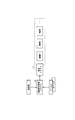
- FIG. 1 is a diagram for explaining the relationship between an operator and a manufacturer in an integrated system in the operation and maintenance management method of the present invention.
- the operation and maintenance management system 10 shown in FIG. 1 generates information for supporting generation of an operation plan and maintenance plan of an integrated system including a plurality of devices and decision making of operation.
- a conventional operation maintenance method will be described for comparison with the operation maintenance method of the integrated system 11 in the present embodiment.
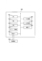
- FIG. 11 is a diagram for explaining the relationship of a business operator or manufacturer to an integrated system in a conventional operation maintenance management method.
- the operator shown in FIG. 11 is an entity that operates the integrated system 11.
- the business operator performs operation and management for each device of the integrated system 11.
- a manufacturer ⁇ and a manufacturer ⁇ are manufacturers of a plurality of devices included in the integrated system 11.
- manufacturer ⁇ manufactures device A and device B, and monitors and maintains device A and device B.
- the manufacturer ⁇ is a manufacturer of the device C, and monitors and maintains the device C.
- the operation is conventionally performed according to a maintenance plan prepared by the business operator or a maintenance plan proposed by the manufacturer ⁇ and the manufacturer ⁇ for each of the devices in charge. Therefore, it is not always clear whether the maintenance work is performed at an optimal time, for example, from the economical point of view as a whole, or whether the content of the maintenance work is appropriate.
- the business operator inputs the operation plan draft of the entire system, which is planned by the operator, to the operation and maintenance management system 10.
- Manufacturer ⁇ and manufacturer ⁇ input to the operation and maintenance management system 10 such as a service plan for each device.
- the operation and maintenance management system 10 combines plans input by the operator and the manufacturer ⁇ , etc., and provides a prediction scenario for an evaluation index related to the operation of the integrated system 11, an operation plan optimized for the evaluation index, a maintenance plan, and the like.
- the operation and maintenance management system 10 creates an operation plan and the like in consideration of economic efficiency based on knowledge possessed by the operator, manufacturer ⁇ , and the like.
- the business operator, the manufacturer ⁇ , and the manufacturer ⁇ operate the integrated system 11 based on their operation plans and the like.
- the prediction scenario is, for example, performance deterioration due to aging of equipment included in the integrated system 11 such as equipment A in addition to information related to prediction of factor fluctuations necessary for decision making of the integrated system operation such as fuel price and product demand.
- information on prediction of economic loss caused by a business operator due to the prediction of failure or the like, performance deterioration of the equipment, failure or the like is included.
- the optimized operation plan is related to, for example, economic benefits that the operator obtains by operating the integrated system 11, economic loss due to performance degradation of the equipment, costs required for equipment maintenance (replacement, upgrade, etc.), etc. This is an appropriate operation plan that can be obtained in consideration of safety.
- the integrated system 11 is, for example, an industrial plant such as a gas turbine, an aircraft, or the like.
- the case where the integrated system 11 is a power plant will be described as an example.
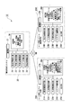
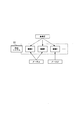
- FIG. 2 is a functional block diagram showing an example of the embodiment of the operation and maintenance management method for the integrated system according to the present invention.
- the operation and maintenance management system 10 shown in FIG. 2 includes user part systems 20A and 20B and an information sharing system 30.
- the user unit systems 20A and 20B and the information sharing system 30 are configured by a computer such as a server terminal device.
- the user unit system 20A, the user unit system 20B, and the information sharing system 30 are communicably connected via a network.
- the user part system 20A is owned by a manufacturer that manufactures the devices included in the integrated system 11. Confidential information such as parts of equipment manufactured by the manufacturer may be recorded in the user unit system 20A.
- the user section system 20B is owned by the business owner that owns the integrated system 11.
- the user section system 20B records highly confidential asset plan information, operation plan information (hereinafter simply referred to as an operation plan), maintenance plan information (hereinafter simply referred to as a maintenance plan), etc. held by the operator. May be.
- the information sharing system 30 data shared by the manufacturer and the operator is recorded.
- the information sharing system 30 performs processing such as creation of a prediction scenario and an operation plan interactively and comprehensively using information that can be made public by the manufacturer and the operator.
- FIG. 2 only one user unit system 20 ⁇ / b> A is described. However, each user unit system 20 ⁇ / b> A is individually owned by each manufacturer related to the devices included in the integrated system 11.
- the user unit system 20A includes a setting information receiving unit 21A, an input information acquiring unit 22A, a prediction information calculating unit 23A, a scenario editing unit 24A, an output unit 25A, a storage unit 26A, and a communication. 27A.
- the setting information receiving unit 21A receives an input of an index used for evaluation of the integrated system and an evaluation period.
- the input information acquisition unit 22A accepts input of information necessary for device maintenance, component upgrade proposal, etc., such as device performance change, upgrade component performance, and price information.
- the input information acquisition unit 22A acquires device operation information (information indicating the operation state of the device detected by a sensor provided in the device) obtained by monitoring the device.
- the prediction information calculation unit 23A calculates prediction information or the like indicating a change with time in the performance of the device.
- the scenario editing unit 24A displays various scenario information created by the information sharing system 30 (hereinafter simply referred to as a scenario).
- the scenario editing unit 24A receives an editing operation for the displayed scenario.
- the output unit 25A outputs the scenario generated by the scenario editing unit 24A to a display or the like.
- the storage unit 26A stores various types of information. For example, in the storage unit 26A, a device information DB (database) including the price of the device, a device performance model indicating the device performance, a device deterioration model indicating a change in the device performance over time, and an upgrade for parts included in the device An upgrade DB including component information is recorded.
- the storage unit 26A stores a list of evaluation indices received by the setting information receiving unit 21A, each item of input information acquired by the input information acquiring unit 22A, and a default value of a prediction curve displayed by the scenario editing unit 24A. The default value indicates that no editing is performed.
- the storage unit 26A may be a storage device included in the user unit system 20A, or may be an external (eg, a data center) storage device.
- the communication unit 27A communicates with other devices.
- the user unit system 20B includes a setting information reception unit 21B, an input information acquisition unit 22B, a prediction information calculation unit 23B, a scenario editing unit 24B, an output unit 25B, a storage unit 26B, and a communication unit 27B.
- the setting information reception unit 21B receives an input of an index and an evaluation period used for evaluation of the integrated system.
- the input information acquisition unit 22B accepts input of information such as an operation plan, a maintenance plan, and the like of the integrated system 11, and predictions of fuel prices, demand predictions, and the like necessary for their creation.
- the prediction information calculation unit 23B calculates the prediction information indicating the transition of the fuel price in the evaluation period based on the predicted value of the fuel price at a certain time in the future acquired by the input information acquisition unit 22B. For example, the prediction information calculation unit 23B calculates prediction information indicating a transition in the evaluation period of the profit obtained by the operation of the integrated system 11 when there is a demand according to the demand prediction acquired by the input information acquisition unit 22B.
- the scenario editing unit 24B displays the scenario created by the information sharing system 30. Accept editing operations for the displayed scenario.
- the output unit 25B outputs and displays the scenario generated by the scenario editing unit 24B on the display.
- the storage unit 26B stores various types of information.
- the storage unit 26B stores a prediction model of fuel and demand, an operation know-how DB that accumulates the operator's operation know-how, maintenance history information for the past integrated system 11, and the like. Such information may be confidential information of the operator.
- the storage unit 26B stores a list of evaluation indices received by the setting information receiving unit 21B, each item of input information acquired by the input information acquiring unit 22B, and a default value of the scenario displayed by the scenario editing unit 24B.
- the storage unit 26B may be a storage device included in the user unit system 20B or an external storage device.
- the communication unit 27B performs communication with other devices.
- the information sharing system 30 includes a setting information reception unit 31, a prediction information acquisition unit 32, a prediction information adjustment unit 33, a scenario calculation unit 34, an evaluation index calculation unit 35, a storage unit 36, and a communication unit 37.
- the setting information receiving unit 31 acquires setting information such as an index and an evaluation period acquired by the setting information receiving unit 21A from the user unit system 20A.
- the setting information receiving unit 31 acquires setting information such as an index and an evaluation period from the user unit system 20B.
- the prediction information acquisition unit 32 acquires the prediction information of the device performance calculated by the prediction information calculation unit 23A from the user unit system 20A.
- the prediction information acquisition unit 32 acquires prediction information such as the fuel price calculated by the prediction information calculation unit 23B and the profit obtained by the operation of the integrated system 11 from the user unit system 20B.
- the prediction information acquisition unit 32 acquires an operation plan and a maintenance plan from the user unit system 20B.
- the prediction information adjustment unit 33 adjusts various prediction information acquired by the prediction information acquisition unit 32.
- the scenario calculation unit 34 aggregates a plurality of prediction information acquired by the prediction information acquisition unit 32 and the prediction information adjusted by the prediction information adjustment unit 33, and calculates an evaluation index used for evaluating the operation of the integrated system 11. Calculate the scenario.
- the scenario calculation unit 34 operates the power plant with the operation plan based on the operation plan acquired by the prediction information acquisition unit 32 and the fuel price prediction information. A scenario showing the transition of the fuel cost required for the case is calculated.
- the evaluation index calculation unit 35 calculates an evaluation index for the scenario calculated by the scenario calculation unit 34.
- storage part 36 memorize
- the storage unit 36 stores the latest operation information of the integrated system 11, a history of past operation information, predicted values of equipment and raw material prices, and the like.
- the storage unit 36 may be a storage device included in the user unit system 20A or 20B, or may be an external storage device.
- the communication unit 37 communicates with other devices.
- the information sharing system 30 acquires various types of information related to the operation of the integrated system 11 from the user unit systems 20A and 20B, and calculates an evaluation index. Next, the flow of evaluation index calculation processing by the information sharing system 30 will be described.
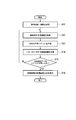
- FIG. 3 is a flowchart showing an example of the embodiment of the operation and maintenance management method for the integrated system according to the present invention.
- the setting information receiving unit 31 of the information sharing system 30 acquires and sets an evaluation index / period from the user unit systems 20A and 20B via the communication unit 37 (step S11). For example, information such as “fuel cost” as an evaluation index and “5 years” as a period is set.
- the prediction information acquisition part 32 acquires the prediction information which considered temporal change from user part system 20A, 20B via the communication part 37 (step S12).
- the prediction information acquisition unit 32 acquires, from the user unit system 20A, performance prediction information for the next five years considering the secular changes of the devices A, B, and C of the power plant (integrated system 11).
- the prediction information acquisition unit 32 acquires, from the user unit system 20B, an operation plan for the future five years, prediction information on the fuel price for the future five years necessary for power generation, and the like.
- the scenario calculation unit 34 creates a future prediction scenario (step S13).
- the prediction scenario includes prediction information for calculating an evaluation index (“fuel cost”) such as fuel and product prices, prediction information acquired from the user unit systems 20A and 20B, and processing information calculated therefrom. Or the final evaluation index prediction information.
- fuel cost such as fuel and product prices
- prediction information acquired from the user unit systems 20A and 20B or the final evaluation index prediction information.
- Each prediction information is simplified to the content that can be disclosed by the holder, and the scenario is expressed by a function having time series data or time as a variable.
- the processing information is an expected curve graph showing “change in fuel cost” for the next five years obtained by multiplying the power generation amount indicated by the operation plan by the fuel price.
- the fact that the final evaluation index may be included indicates that, for example, when the evaluation index is “fuel cost”, the above-described prediction curve graph indicating “change in fuel cost” is a scenario.
- the evaluation index calculation unit 35 calculates an evaluation index for the scenario (step S14). For example, the evaluation index calculation unit 35 calculates the value of the evaluation index “fuel cost” by accumulating the fuel cost during the evaluation period in the prediction curve graph indicating “transition of fuel cost”.
- the scenario calculation unit 34 determines whether or not a scenario to be compared is prepared (step S15). For example, the evaluation index “fuel cost” is simulated for one type of “fuel price prediction”, one type of “performance prediction”, and three types of “operation plan” (operation plans A, B, C). If an operation plan that is most excellent in terms of “fuel cost” is selected from the three types of “operation plans”, the scenario to be compared is “fuel cost” for the three types of “operation plans”. Is a prediction scenario.
- the processing from step S12 is repeated until the scenarios to be compared are prepared.
- the five-year fuel cost calculated based on the prediction curve (scenario) indicating the transition of the fuel cost in the future five years of the operation plans A, B and C has been calculated. Yes.
- the evaluation index calculation unit 35 transmits the calculated evaluation index to the user unit systems 20A and 20B via the communication unit 37.
- the output unit 25A compares and displays the calculation result of the evaluation index (step S16).
- the output unit 25A outputs information such as X circle for the operation plan A, Y circle for the operation plan B, Z circle for the operation plan C, and the like. The same applies to the user unit system 20B.
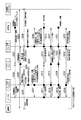
- FIG. 4 is a sequence diagram showing an example of the embodiment of the operation and maintenance management method for the integrated system according to the present invention.
- the storage unit 26B of the user unit system 20B is configured as an external storage device (for example, a storage device provided in a so-called cloud computing system).
- the business operator uses the user part system 20B to start an evaluation process (step S201). Specifically, the business operator inputs information on an evaluation index (for example, “fuel cost”) and an evaluation period (for example, “5 years”) to the user part system 20B.
- an evaluation index for example, “fuel cost”
- an evaluation period for example, “5 years
- the setting information reception unit 21B acquires the information and transmits it to the information sharing system 30 via the communication unit 27B.
- the setting information receiving unit 31 acquires the information via the communication unit 37 and records it in the storage unit 36. This process may be performed by the manufacturer (step S202).
- the prediction information acquisition unit 32 of the information sharing system 30 requests input information from the device A (step S203).
- the prediction information acquisition unit 32 requests input information from the external storage device (step S203 ′).
- the prediction information acquisition unit 32 requests the user unit system 20A for input information such as information indicating a change in device performance, upgrade proposal information (such as upgrade component performance and price) (step S204).
- the prediction information acquisition unit 32 requests input information such as an operation plan and a maintenance plan from the user unit system 20B (step S204 ′).
- the device A transmits a history (history information) of operation information of the device A (information measured by a sensor provided in the device A) to the user unit system 20A (step S205).
- the external storage device transmits the fuel price and the demand prediction information to the user part system 20B (step S206).
- the processes in steps S205 and S206 are not essential, and may be data input via the user unit systems 20A and 20B, respectively.
- the manufacturer sets a prediction curve and a starting value in the user part system 20A.
- the output unit 25A displays an input screen that prompts input of necessary information (step S207).
- the manufacturer inputs the current performance of the device A as a starting value on the input screen.
- the manufacturer inputs the performance of the device A after a predetermined time has passed (fill-in type input).
- the maker ⁇ may correct the values of the performance information of the device A by referring to the current state of the device A with respect to the predetermined performance information for the predetermined departure value and the predetermined time elapsed, These values may be corrected with reference to the track record of changes in the performance of the device A.
- the performance information of the future device A may be used as the performance information of the future device A by diverting the track record of the past changes in the performance of the device A.
- the manufacturer inputs information specifying a calculation model for calculating the performance of the device A and an input value (starting value) to the model.
- the manufacturer inputs the performance information of the device A extracted from the monitoring information (step S211). At this time, the manufacturer inputs only information that may be disclosed to the business operator.
- the input information acquisition unit 22A acquires information input by the manufacturer and transmits it to the information sharing system 30 via the communication unit 27A (step S212). In the information sharing system 30, the prediction information acquisition unit 32 acquires this information and records it in the storage unit 36.
- the business operator sets a prediction curve and a starting value in the user part system 20B.
- the output unit 25B displays an input screen that prompts input of necessary information (step S208).
- the business operator inputs the current power generation amount (operation plan) and the current fuel price as starting values on the input screen.
- the business operator inputs the power generation amount and fuel price predicted value after a predetermined time has elapsed (fill-in type input).
- the operator may refer to the current fuel price with respect to the starting value of the fuel price and the predicted value of the fuel price every predetermined time, and correct those values, or may change the past fuel price over time. These values may be corrected with reference to the actual change.
- past fuel prices may be used as future fuel prices by diverting past results of changes in fuel prices over time.
- the business operator inputs information specifying a calculation model for calculating a target power generation amount and a predicted value of the fuel price and an input value (departure value) to the model.
- the business operator inputs the prediction information of the fuel price extracted from the information (step S213). At this time, the business operator inputs only information that may be disclosed to the manufacturer.
- the input information acquisition unit 22B acquires information input by the operator and transmits the information to the information sharing system 30 via the communication unit 27B (step S214). In the information sharing system 30, the prediction information acquisition unit 32 acquires this information and records it in the storage unit 36.
- the scenario calculation unit 34 aggregates the prediction information acquired by the prediction information acquisition unit 32 and creates an adjusted scenario.
- an example is given and demonstrated about a scenario using FIG.
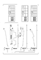
- FIG. 5 is a diagram showing an example of a scenario used in the operation and maintenance management method of the integrated system according to the present invention.
- a graph 5 ⁇ / b> A shown in FIG. 5A is fuel price prediction information calculated by the scenario calculation unit 34.
- a graph 5B illustrated in FIG. 5B is operation plan prediction information calculated by the scenario calculation unit 34.
- the table shown to the right of these two graphs is an example of the input screen displayed in step S208.
- the business operator inputs the fuel price for each predetermined period up to Tm, which is the end time of the evaluation period, and the predicted value of the operation plan. For example, the business operator inputs a scheduled value at a time when maintenance is scheduled based on the maintenance plan.
- the prediction information calculation unit 23B calculates the transition of the fuel price during the evaluation period (T0 to Tm) based on the fuel price for each predetermined period input by the operator and the economic prediction model of the storage unit 26B. Prediction information (graph 5A) shown in (a) is generated. The prediction information calculation unit 23B calculates an operation plan during the evaluation period based on the operation plan for each predetermined period input by the operator and the operation know-how DB of the storage unit 26B, and the prediction information shown in FIG. (Graph 5B) is generated. The inspection / maintenance in the period T1 to T2 in the graph 5B is based on the plan information input by the operator.
- the solid line portions in FIGS. 5A and 5B are real data, and the broken line portions are prediction information.
- the economic prediction model or the like used by the prediction information calculation unit 23B is not a precise prediction model used by the operator itself, but may be a prediction model that is estimated with an accuracy that can be disclosed to the manufacturer by the operator.
- the prediction information calculation unit 23B transmits the prediction information to the information sharing system 30 via the communication unit 27B.
- the graph shown in FIG. 5C is the performance prediction information of the device A calculated by the scenario calculation unit 34.
- the table on the right side of this graph is an example of the input screen displayed in step S207.
- the manufacturer ⁇ inputs the predicted value of the performance information of the devices A and B for each predetermined period until the end time Tm of the evaluation period.
- the prediction information calculation unit 23A based on the performance information of the device A for each predetermined period input by the manufacturer ⁇ and the device performance model, device deterioration model, etc. of the storage unit 26A, the device A during the evaluation period (T0 to Tm). The transition of the performance information is calculated, and the prediction information (graph 5C-1) shown in FIG. 5C is generated.
- the prediction information calculation unit 23A calculates an operation plan during the evaluation period based on the operation plan for each predetermined period input by the operator, and generates prediction information (graph 5C-1) shown in FIG. .
- the solid line portion in FIG. 5C is real data, and the broken line portion is prediction information.
- the performance deterioration model or the like used by the scenario calculation unit 34 may not be a more accurate model as long as it has an accuracy capable of achieving the purpose of the index calculation.
- the prediction information calculation unit 23A transmits the prediction information to the information sharing system 30 via the communication unit 27A.
- the scenario calculation unit 34 aggregates the prediction information and creates an adjusted scenario. For example, the scenario calculation unit 34 aggregates the prediction information in FIG. 5B and the graph 5C-1 in FIG. 5C to create a prediction scenario for the evaluation index reflecting the operation plan. At that time, the prediction information adjustment unit 33 calculates the influence on the device A by the inspection / maintenance at the times T1 to T2 included in FIG. More specifically, the prediction information adjustment unit 33 calculates the performance information of the device A that is improved by inspection / maintenance. The prediction information adjustment unit 33 outputs performance information to the scenario calculation unit 34. The scenario calculation unit 34 generates prediction information (graph 5C-2) reflecting performance information for improvement.
- the prediction information shown in these graphs 5A, 5B, and 5C-2 constitutes a part of the scenario, and each is a scenario.
- the graph 5C-1 can also be used as a comparison target for grasping the effect of inspection / maintenance as a scenario when inspection / maintenance is not performed.
- the graph shown in FIG. 5D is evaluation index prediction information created by the scenario calculation unit 34.
- the scenario calculation unit 34 aggregates the graphs 5A, 5B, and 5C-2 and creates prediction information (graph 5D) that indicates the transition of the fuel cost during the evaluation period. For example, the scenario calculation unit 34 calculates the transition of the fuel amount necessary for execution of the operation plan based on the operation plan prediction graph 5B and the performance prediction graph 5C-2.
- the scenario calculation unit 34 creates a graph 5D by multiplying the required fuel amount by the fuel price predicted in the graph 5A. If the performance of the equipment decreases as the operating time increases, the required fuel increases even if a certain amount of power generation is planned.
- the scenario calculation unit 34 calculates the fuel cost at the time T0 and the fuel cost at the time T0 + ⁇ T, creates the table shown on the right side of FIG. 5D, and creates the table created through the user unit systems 20A and 20B. Present to manufacturers and operators.
- the prediction information adjustment unit 33 converts the prediction information (graph 5C-1) of a certain input information over time into the prediction information of another input information over time (performance information of the device A improved by inspection and maintenance).
- the scenario calculation unit 34 aggregates the adjusted prediction information and creates a scenario.
- the scenario calculation unit 34 transmits the created scenario to the user unit system 20A via the communication unit 37 (step S215).
- the scenario editing part 24A acquires the information via the communication part 27A, and displays the scenario via the output part 25A (step S216).
- the scenario calculation unit 34 transmits the created scenario to the user unit system 20B via the communication unit 37 (step S217), and the scenario editing unit 24B displays the scenario via the output unit 25B (step S218). ).
- the manufacturer confirms the contents of the scenario and performs an editing operation on the scenario (step S219). For example, the manufacturer makes a correction to the graph 5C-2 in FIG. For example, when the performance improvement after inspection / maintenance is insufficient, the manufacturer corrects the graph so that the performance is further improved. Based on the operation information and history information acquired from the device A and the operation plan prediction graph 5B based on the information provided by the operator, the performance deterioration is more severe than that shown in the graph 5C-2. If it is predicted that the degradation will occur (or if the performance degradation is expected to decrease), the manufacturer edits the slope of the graph 5C-2 so as to be larger (smaller).
- the scenario editing unit 24A receives the editing operation of the manufacturer and creates the edited graph 5C-2.
- the scenario editing unit 24B transmits the edited graph 5C-2 to the information sharing system 30 via the communication unit 27A (step S220).
- the scenario calculation unit 34 acquires the edited graph 5C-2 (finalized scenario) via the communication unit 37 and records it in the storage unit 36.
- the business operator confirms the contents of the scenario and performs an editing operation (step S221). For example, the business operator edits the operation time longer or shorter than the graph 5B in FIG. Alternatively, editing is performed on the graph 5A indicating the fuel price so as to obtain, for example, a graph that suppresses an increase in price.
- the scenario editing unit 24B accepts the operator's editing operation and creates the edited graphs 5A and 5B.
- the scenario editing unit 24B transmits the edited graphs 5A and 5B to the information sharing system 30 via the communication unit 27B (step S222).
- the scenario calculation unit 34 acquires the edited graphs 5 ⁇ / b> A and 5 ⁇ / b> B (finalized scenarios) via the communication unit 37 and records them in the storage unit 36.
- the scenario calculation unit 34 reads out the edited graphs 5A, 5B, and 5C-2 from the storage unit 36, and recreates the graph 5D based on the edited graphs 5A, 5B, and 5C-2.
- the evaluation index calculation unit 35 calculates an evaluation index for the scenario. Specifically, the evaluation index calculation unit 35 integrates the fuel cost in the evaluation period of 5 years using the re-created graph 5D.
- the evaluation index calculation unit 35 transmits the calculated fuel cost to the user unit system 20A via the communication unit 37 (step S223).
- the user unit system 20A acquires the evaluation index value via the communication unit 27A, and the output unit 25A outputs the evaluation index value (5-year fuel cost) (step S224).
- the evaluation index calculation unit 35 transmits the fuel cost for five years to the user unit system 20B via the communication unit 37 (step S225).
- the user unit system 20B acquires the fuel cost via the communication unit 27B, and the output unit 25B outputs the fuel cost (step S226).
- Companies and manufacturers can edit scenarios and input prediction information repeatedly, and create scenarios and calculate evaluation index values until they are satisfied with each other.
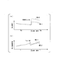
- FIG. 6 is a diagram showing an example of scenario comparison regarding the presence / absence of upgrade in the integrated system according to the present invention.
- FIG. 6A shows a scenario of the prediction information of the performance of the device A.
- a graph 6A-1 shows prediction information of the performance of the device A when the device A is repaired without performing parts replacement or the like for inspection / maintenance.
- Graph 6A-2 shows the prediction information of the performance of device A when upgrade parts are applied to device A for inspection and maintenance. If upgrade parts are applied as shown in the figure, significant performance improvement can be expected.
- FIG. 6B shows a comparative display example (step S16 in FIG. 3) of the evaluation index (fuel cost).
- a graph 6B-1 shows fuel cost prediction information when only repair is performed on the device A during inspection and maintenance.
- Graph 6B-2 shows the prediction information of the fuel cost when the device A is replaced with an upgrade part for inspection / maintenance.
- upgrade parts are applied as shown in the figure, a temporary cost burden is generated.
- the performance improvement by the upgrade parts can exhibit the same performance as the case where the upgrade parts are not applied with less fuel in the subsequent operation. Therefore, an increase in cost after the upgrade can be suppressed (graph 6B-2).
- the operation and maintenance management system 10 includes the prediction information calculation units 23A and 23B. Accordingly, it is possible to formulate a maintenance plan and the like after calculating the economic index in consideration of the influence of the performance deterioration due to the continued operation of the integrated system 11 and the fluctuation of the fuel price.
- both the manufacturer and the operator can disclose the highly accurate prediction information possessed by themselves (for example, the performance degradation information of parts for the manufacturer, the fuel price for the operator, etc.). It is possible to share the information and to evaluate the evaluation index interactively and comprehensively based on each information. For example, in the fuel cost index calculation in steps S211 and S213 in the sequence diagram of FIG. 4, necessary input information is clearly shown on the input screen to the manufacturer and the operator via the user part systems 20A and 20B, respectively. Information may be shared with each other as a hole filling method that fills a place where the can be input.
- an input screen for inputting necessary input information by a business operator and a manufacturer
- an input area as shown in the right table of FIGS. 5A and 5C is displayed so that items in charge of each other are filled.
- the user unit system 20B displays an input screen with price prediction and operation plan as input items and performance information of the devices A and B as display items.
- the manufacturer inputs performance information such as the device A
- the user part system 20B displays an input screen displaying the performance information input by the manufacturer in the display item of the device A.
- the user part system 20A displays an input screen displaying the information input by the business operator in the display items of price prediction and operation plan.
- the prediction information calculation units 23A and 23B may calculate the prediction information based on the model, and the scenario calculation unit 34 may calculate the prediction information of the evaluation index based on the model.
- an operation plan and a maintenance plan can be formulated in real time.
- the evaluation index is “fuel cost” and, for example, an appropriate operation plan is selected or whether or not to upgrade parts is determined.
- the operation and maintenance management system 10 will be described by taking as an example the case where the gas turbine repair / maintenance timing is formulated with the evaluation index “timing when the economic deterioration cost exceeds the repair / maintenance cost”.
- the economic deterioration cost is a lost profit due to a decrease in performance of the gas turbine.
- the economic degradation cost is represented by a total of, for example, a decrease in profit due to a decrease in power generation efficiency, an increase in cost due to an increase in power consumption at the facility, and an increase in cost due to an increase in failure occurrence rate.
- the repair / maintenance cost is a cost necessary for performing the repair / maintenance.
- FIG. 7 is a diagram illustrating an example of cost evaluation when the operation and maintenance management method for the integrated system according to the present invention is applied to a power generation facility.
- FIG. 7A shows prediction information (graph 7A) indicating a change in power generation efficiency over time. As the graph 7A shows, the power generation efficiency of the gas turbine decreases as the operation time increases due to deterioration over time. If the power generation efficiency decreases, the revenue from power sales decreases.
- the graph 7A is based on plant operation information, performance information, and a deterioration model input by the manufacturer to the user part system 20A.
- FIG. 7 (b) shows prediction information (graph 7B) indicating a change with time of power consumption by the power plant equipment.
- graph 7B shows prediction information (graph 7B) indicating a change with time of power consumption by the power plant equipment.
- the graph 7B is based on operation information, performance information, and a deterioration model of equipment and peripheral equipment included in the gas turbine that the manufacturer inputs to the user part system 20A.
- FIG. 7 (c) shows prediction information (graph 7C) showing a change with time of the failure occurrence rate due to a failure of the equipment provided in the gas turbine.
- graph 7C shows prediction information showing a change with time of the failure occurrence rate due to a failure of the equipment provided in the gas turbine.
- the failure occurrence rate of each facility increases with an increase in operation time due to deterioration over time.
- the maintenance cost for repairing the failure increases.
- the graph 7C is based on the operation information, performance information, and deterioration model of each facility of the plant that the manufacturer inputs to the user part system 20A.
- the manufacturer and the operator input the cost information required for repairing the components of each device included in the gas turbine and the prediction information for calculating the decrease in profit due to the operation stop for maintenance in the user unit systems 20A and 20B, respectively. .
- the manufacturer inputs information indicating the cost of repairing the components of each device and how much time is required for the repair to the user unit system 20A.
- the business operator inputs information indicating an economic loss per unit time due to the operation stop (lost profit due to the inability to generate power during that time) to the user unit system 20B.
- the prediction information calculation unit 23A calculates cost prediction information (generally, the cost increases as the operation time increases) for repairing the components of each device included in the gas turbine.
- the prediction information calculation unit 23B calculates the lost profit prediction information (for example, the lost profit fluctuates even if it is stopped for the same period of time based on the prediction of the future power selling unit price, etc.).
- the scenario calculator 34 aggregates these prediction information and calculates the prediction information of the repair / maintenance cost.
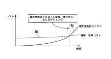
- FIG. 8 is a diagram showing an example of a maintenance plan setting based on the cost when the operation and maintenance management method for the integrated system according to the present invention is applied to a power generation facility.
- FIG. 8 shows a graph 8A showing prediction information of economic deterioration cost and a graph 8B showing prediction information of repair / maintenance cost.
- the scenario calculation unit 34 aggregates the graphs 7A, 7B, and 7C to calculate economic deterioration cost prediction information (graph 8A).
- the scenario calculation unit 34 calculates repair / maintenance cost prediction information (graph 8B) as described above.
- the graph 8A shows an example of a decrease in economic performance (an increase in cost) due to performance deterioration of the power plant.
- FIG. 8 is a diagram in which “economic degradation cost” and “repair / maintenance cost” are compared and displayed when the evaluation index is “timing when economic degradation cost exceeds repair / maintenance cost”.
- the evaluation index calculation unit 35 calculates the timing at which repair / maintenance cost ⁇ economic deterioration cost is satisfied, and sets the economically optimized repair / maintenance schedule.
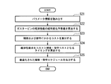
- FIG. 9 is a flowchart showing an example of a maintenance plan setting based on the cost when the operation and maintenance management method for the integrated system according to the present invention is applied to the power generation equipment.
- the prediction information calculation units 23A and 23B read parameter information (performance information, deterioration model, economic loss due to operation stop, etc.) input by the manufacturer and the operator (step S21).
- the prediction information calculation units 23A and 23B calculate a predicted change with time of the economic performance of the gas turbine.
- the scenario calculation unit 34 calculates a prediction information (graph 8A) of the economic deterioration cost by aggregating a plurality of predicted change values with time (step S22).
- the scenario calculation unit 34 aggregates the cost of repair, the time required for repair, and the predicted information of economic loss per unit time due to operation stop, and calculates the predicted information of repair / maintenance cost (graph 8B) (step 8) S23).
- the evaluation index calculation unit 35 calculates the timing at which the economic deterioration cost> the repair / maintenance cost (step S24).
- the evaluation index calculation unit 35 transmits the calculated timing to the user unit systems 20A and 20B.
- the output part 25A outputs an optimized repair / maintenance schedule.
- the output unit 25B outputs the optimized repair / maintenance schedule (step S25).
- the schedule is set so as to minimize the operation stop time, and the economic performance due to the deterioration of the equipment is not considered.
- an economically optimal repair or maintenance schedule can be set.
- the maintenance schedule set by the operator is used as a reference scenario, and this is edited as a scenario that reflects the new maintenance schedule proposed by the manufacturer. If the calculation results are compared, the effect of the manufacturer proposal can be easily communicated to the operator.
- the user unit systems 20A and 20B and the information sharing system 30 can be realized using, for example, a general computer 500.
- FIG. 10 shows an example of the configuration of the computer 500.
- FIG. 10 is a diagram showing an example of a hardware configuration of the user part systems 20A and 20B and the information sharing system 30 according to the present invention.
- the computer 500 includes a CPU (Central Processing Unit) 501, a RAM (Random Access Memory) 502, a ROM (Read Only Memory) 503, a storage device 504, an external I / F (Interface) 505, an input device 506, an output device 507, communication. I / F508 and the like. These devices transmit and receive signals to and from each other via the bus B.
- the CPU 501 is an arithmetic unit that realizes each function of the computer 500 by reading a program and data stored in the ROM 503, the storage device 504, and the like onto the RAM 502 and executing processing.
- the prediction information calculation units 23A and 23B and the scenario calculation unit 34 described above are functions provided in the computer 500 when the CPU 501 reads and executes a program stored in the ROM 503 or the like.
- a RAM 502 is a volatile memory used as a work area for the CPU 501.
- the ROM 503 is a nonvolatile memory that retains programs and data even when the power is turned off.
- the storage device 504 is realized by, for example, an HDD (Hard Disk Drive), an SSD (Solid State Drive) or the like, and stores an OS (Operation System), application programs, various data, and the like.
- the external I / F 505 is an interface with an external device. Examples of the external device include a recording medium 509.
- the computer 500 can read and write the recording medium 509 via the external I / F 505.
- the recording medium 509 includes, for example, an optical disk, a magnetic disk, a memory card, a USB (Universal Serial Bus) memory, and the like.
- the input device 506 includes, for example, a mouse and a keyboard, and inputs various operations and the like to the computer 500 in response to instructions from the operator.
- the output device 507 is realized by a liquid crystal display, for example, and displays a processing result by the CPU 501.
- the communication I / F 508 is an interface that connects the computer 500 to a network such as the Internet by wired communication or wireless communication.
- the bus B is connected to each of the above constituent devices, and transmits and receives various control signals and the like between the control devices.
- Each process of the above-described user unit systems 20A and 20B and information sharing system 30 is stored in a computer-readable recording medium in the form of a program, and this program is read and executed by the computer of the delivery planning system.
- the computer-readable recording medium means a magnetic disk, a magneto-optical disk, a CD-ROM, a DVD-ROM, a semiconductor memory, or the like.
- the computer program may be distributed to the computer via a communication line, and the computer that has received the distribution may execute the program.
- the program may be for realizing a part of the functions described above. Furthermore, what can implement
- the user unit systems 20A and 20B and the information sharing system 30 may be configured by a single computer, or may be configured by a plurality of computers connected to be communicable.
- Operation and maintenance management system 20A, 20B user part system, 21A, 21B Setting information receiving unit, 22A, 22B input information acquisition unit, 23A, 23B prediction information calculation unit, 24A, 24B Scenario editing department, 25A, 25B output section, 26A, 26B storage unit, 27A, 27B communication section, 30 Information sharing system, 31 Setting information reception part, 32 prediction information acquisition unit, 33 prediction information adjustment unit, 34 Scenario calculation part, 35 evaluation index calculation unit, 36 storage unit, 37 Communication Department
Landscapes
- Engineering & Computer Science (AREA)
- Business, Economics & Management (AREA)
- Human Resources & Organizations (AREA)
- General Physics & Mathematics (AREA)
- Physics & Mathematics (AREA)
- Strategic Management (AREA)
- Economics (AREA)
- Entrepreneurship & Innovation (AREA)
- Combustion & Propulsion (AREA)
- Chemical & Material Sciences (AREA)
- Educational Administration (AREA)
- Quality & Reliability (AREA)
- Operations Research (AREA)
- Theoretical Computer Science (AREA)
- Development Economics (AREA)
- Tourism & Hospitality (AREA)
- Marketing (AREA)
- General Business, Economics & Management (AREA)
- Mechanical Engineering (AREA)
- General Engineering & Computer Science (AREA)
- Automation & Control Theory (AREA)
- Game Theory and Decision Science (AREA)
- Management, Administration, Business Operations System, And Electronic Commerce (AREA)
- Testing And Monitoring For Control Systems (AREA)
Priority Applications (3)
| Application Number | Priority Date | Filing Date | Title |
|---|---|---|---|
| DE112018001757.5T DE112018001757T5 (de) | 2017-03-29 | 2018-03-22 | Betriebs-/Wartungsmanagementverfahren, Programm und Betriebs-/Wartungsmanagementsystem |
| US16/494,814 US11500369B2 (en) | 2017-03-29 | 2018-03-22 | Operation/maintenance management method, program, and operation/maintenance management system |
| CN201880019957.7A CN110462648B (zh) | 2017-03-29 | 2018-03-22 | 运行维护管理方法、记录介质以及运行维护管理系统 |
Applications Claiming Priority (2)
| Application Number | Priority Date | Filing Date | Title |
|---|---|---|---|
| JP2017065958A JP6966857B2 (ja) | 2017-03-29 | 2017-03-29 | 運転保守管理方法、プログラム、及び運転保守管理システム |
| JP2017-065958 | 2017-03-29 |
Publications (1)
| Publication Number | Publication Date |
|---|---|
| WO2018180904A1 true WO2018180904A1 (ja) | 2018-10-04 |
Family
ID=63675750
Family Applications (1)
| Application Number | Title | Priority Date | Filing Date |
|---|---|---|---|
| PCT/JP2018/011459 Ceased WO2018180904A1 (ja) | 2017-03-29 | 2018-03-22 | 運転保守管理方法、プログラム、及び運転保守管理システム |
Country Status (5)
| Country | Link |
|---|---|
| US (1) | US11500369B2 (enExample) |
| JP (1) | JP6966857B2 (enExample) |
| CN (1) | CN110462648B (enExample) |
| DE (1) | DE112018001757T5 (enExample) |
| WO (1) | WO2018180904A1 (enExample) |
Cited By (1)
| Publication number | Priority date | Publication date | Assignee | Title |
|---|---|---|---|---|
| WO2025158489A1 (ja) * | 2024-01-22 | 2025-07-31 | 三菱電機株式会社 | 保守計画作成支援装置、保守計画作成支援方法、及び保守計画作成支援プログラム |
Families Citing this family (8)
| Publication number | Priority date | Publication date | Assignee | Title |
|---|---|---|---|---|
| JP6966857B2 (ja) * | 2017-03-29 | 2021-11-17 | 三菱重工業株式会社 | 運転保守管理方法、プログラム、及び運転保守管理システム |
| JP7257225B2 (ja) * | 2019-04-05 | 2023-04-13 | 三菱重工業株式会社 | 作業スケジュール作成システム及び作業スケジュール作成方法 |
| JP7276445B2 (ja) * | 2019-06-20 | 2023-05-18 | コニカミノルタ株式会社 | 維持管理方法、維持管理装置および維持管理プログラム |
| US20230024909A1 (en) * | 2019-12-10 | 2023-01-26 | Daikin Industries, Ltd. | Maintenance assistance system |
| JP2021196989A (ja) * | 2020-06-17 | 2021-12-27 | 三菱重工業株式会社 | 計画装置、計画方法およびプログラム |
| US20220097864A1 (en) * | 2020-09-30 | 2022-03-31 | Ge Avio S.R.L. | Aircraft performance optimization based on engine performance monitoring |
| JP7428157B2 (ja) * | 2021-03-26 | 2024-02-06 | 横河電機株式会社 | 解析装置、解析方法およびプログラム |
| WO2024171613A1 (ja) * | 2023-02-14 | 2024-08-22 | ギガフォトン株式会社 | 表示方法及び表示装置 |
Citations (4)
| Publication number | Priority date | Publication date | Assignee | Title |
|---|---|---|---|---|
| JPH11142298A (ja) * | 1997-11-05 | 1999-05-28 | Babcock Hitachi Kk | ライフサイクルマネジメント型プラント保守支援システム |
| JP2003099119A (ja) * | 2001-09-25 | 2003-04-04 | Mitsubishi Heavy Ind Ltd | 最適保守計画決定方法 |
| JP2014106627A (ja) * | 2012-11-26 | 2014-06-09 | Mitsubishi Heavy Ind Ltd | アップグレード計画支援装置 |
| JP2016192064A (ja) * | 2015-03-31 | 2016-11-10 | 三菱電機株式会社 | 費用予測装置およびプログラム |
Family Cites Families (6)
| Publication number | Priority date | Publication date | Assignee | Title |
|---|---|---|---|---|
| JP2007257376A (ja) * | 2006-03-23 | 2007-10-04 | Mitsubishi Heavy Ind Ltd | プラント用運転管理支援システム |
| US8370046B2 (en) | 2010-02-11 | 2013-02-05 | General Electric Company | System and method for monitoring a gas turbine |
| JP6570396B2 (ja) | 2015-09-29 | 2019-09-04 | 太平洋セメント株式会社 | 左官用粉末状セメント組成物および左官用モルタル |
| JP6966857B2 (ja) * | 2017-03-29 | 2021-11-17 | 三菱重工業株式会社 | 運転保守管理方法、プログラム、及び運転保守管理システム |
| JP6812312B2 (ja) * | 2017-06-21 | 2021-01-13 | 三菱重工業株式会社 | プラント支援評価システム及びプラント支援評価方法 |
| JP7412414B2 (ja) * | 2019-03-22 | 2024-01-12 | 三菱重工サーマルシステムズ株式会社 | 制御装置、機器制御システム、制御方法及びプログラム |
-
2017
- 2017-03-29 JP JP2017065958A patent/JP6966857B2/ja active Active
-
2018
- 2018-03-22 DE DE112018001757.5T patent/DE112018001757T5/de active Pending
- 2018-03-22 CN CN201880019957.7A patent/CN110462648B/zh active Active
- 2018-03-22 US US16/494,814 patent/US11500369B2/en active Active
- 2018-03-22 WO PCT/JP2018/011459 patent/WO2018180904A1/ja not_active Ceased
Patent Citations (4)
| Publication number | Priority date | Publication date | Assignee | Title |
|---|---|---|---|---|
| JPH11142298A (ja) * | 1997-11-05 | 1999-05-28 | Babcock Hitachi Kk | ライフサイクルマネジメント型プラント保守支援システム |
| JP2003099119A (ja) * | 2001-09-25 | 2003-04-04 | Mitsubishi Heavy Ind Ltd | 最適保守計画決定方法 |
| JP2014106627A (ja) * | 2012-11-26 | 2014-06-09 | Mitsubishi Heavy Ind Ltd | アップグレード計画支援装置 |
| JP2016192064A (ja) * | 2015-03-31 | 2016-11-10 | 三菱電機株式会社 | 費用予測装置およびプログラム |
Cited By (1)
| Publication number | Priority date | Publication date | Assignee | Title |
|---|---|---|---|---|
| WO2025158489A1 (ja) * | 2024-01-22 | 2025-07-31 | 三菱電機株式会社 | 保守計画作成支援装置、保守計画作成支援方法、及び保守計画作成支援プログラム |
Also Published As
| Publication number | Publication date |
|---|---|
| US11500369B2 (en) | 2022-11-15 |
| CN110462648A (zh) | 2019-11-15 |
| DE112018001757T5 (de) | 2019-12-19 |
| JP6966857B2 (ja) | 2021-11-17 |
| JP2018169760A (ja) | 2018-11-01 |
| CN110462648B (zh) | 2023-04-28 |
| US20200278671A1 (en) | 2020-09-03 |
Similar Documents
| Publication | Publication Date | Title |
|---|---|---|
| WO2018180904A1 (ja) | 運転保守管理方法、プログラム、及び運転保守管理システム | |
| US9957843B2 (en) | Methods and systems for enhancing control of power plant generating units | |
| US9926852B2 (en) | Methods and systems for enhancing control of power plant generating units | |
| US9960598B2 (en) | Methods and systems for enhancing control of power plant generating units | |
| US9932907B2 (en) | Methods and systems for enhancing control of power plant generating units | |
| US10417614B2 (en) | Controlling aircraft operations and aircraft engine components assignment | |
| US20140006088A1 (en) | Automated scheduling of non-routine maintenance to systems of capital assets | |
| US9576327B2 (en) | Managing time-substitutable electricity usage using dynamic controls | |
| US20120166249A1 (en) | Asset management system | |
| US20160147204A1 (en) | Methods and systems for enhancing control of power plant generating units | |
| US20170323231A1 (en) | Computing system to control the use of physical state attainment of assets to meet temporal performance criteria | |
| US20160231716A1 (en) | System of systems optimizing control for achieving performance and risk outcomes in physical and business operations of connected and interrelated industrial systems | |
| GB2534981A (en) | Methods and systems for enhancing control of power plant generating units | |
| JP2017116984A (ja) | 計画調整システムおよび計画調整方法 | |
| Uvet et al. | Decreasing e-waste through reliability enhancement encouraged by performance-based contracting | |
| KR20190043571A (ko) | 안내 정보 제시 시스템, 안내 정보 제시 방법, 기록 매체에 저장된 프로그램 및 안내 정보 제시 장치 | |
| Fleten et al. | Applying and benchmarking a stochastic programming-based bidding strategy for day-ahead hydropower scheduling | |
| US10268973B2 (en) | Systems, methods and apparatus for a stakeholder market simulator for energy delivery systems | |
| JP2022116423A (ja) | 電力取引支援装置 | |
| JP2008021170A (ja) | 発電所の価値評価システムおよびそのプログラム | |
| JP2010272068A (ja) | 設備管理装置 | |
| JP4393749B2 (ja) | 情報処理装置、情報処理方法及びプログラム | |
| Yan et al. | Sustainable policies for a disruptions-tolerant production network model with green investment and incentive scheme amid various quality inspection setups: R. Karmakara et al. | |
| JP2019083601A (ja) | 発電計画策定装置、発電計画策定方法、および発電計画策定プログラム | |
| Eldridge et al. | Wholesale Electricity Analysis via Simulation & Learning Experiments (WEASLE): Platform Development and Pilot Competition |
Legal Events
| Date | Code | Title | Description |
|---|---|---|---|
| 121 | Ep: the epo has been informed by wipo that ep was designated in this application |
Ref document number: 18776665 Country of ref document: EP Kind code of ref document: A1 |
|
| 122 | Ep: pct application non-entry in european phase |
Ref document number: 18776665 Country of ref document: EP Kind code of ref document: A1 |