WO2018180262A1 - 作業機械及び作業機械の制動方法 - Google Patents
作業機械及び作業機械の制動方法 Download PDFInfo
- Publication number
- WO2018180262A1 WO2018180262A1 PCT/JP2018/008429 JP2018008429W WO2018180262A1 WO 2018180262 A1 WO2018180262 A1 WO 2018180262A1 JP 2018008429 W JP2018008429 W JP 2018008429W WO 2018180262 A1 WO2018180262 A1 WO 2018180262A1
- Authority
- WO
- WIPO (PCT)
- Prior art keywords
- autonomous
- brake
- valve
- hydraulic
- pressure oil
- Prior art date
Links
- 238000000034 method Methods 0.000 title claims abstract description 11
- 239000010720 hydraulic oil Substances 0.000 claims abstract description 37
- 230000004044 response Effects 0.000 claims abstract description 5
- 239000003921 oil Substances 0.000 claims description 77
- 238000011144 upstream manufacturing Methods 0.000 claims description 4
- 230000000994 depressogenic effect Effects 0.000 abstract description 2
- 230000007704 transition Effects 0.000 description 30
- 230000006870 function Effects 0.000 description 29
- 230000008859 change Effects 0.000 description 12
- 238000001514 detection method Methods 0.000 description 5
- 238000010586 diagram Methods 0.000 description 4
- 238000005065 mining Methods 0.000 description 4
- 230000004913 activation Effects 0.000 description 3
- 230000008569 process Effects 0.000 description 3
- 238000004891 communication Methods 0.000 description 2
- 238000012423 maintenance Methods 0.000 description 2
- 230000005540 biological transmission Effects 0.000 description 1
- 230000000881 depressing effect Effects 0.000 description 1
- 230000000694 effects Effects 0.000 description 1
- 238000005516 engineering process Methods 0.000 description 1
- 238000004519 manufacturing process Methods 0.000 description 1
- 238000012986 modification Methods 0.000 description 1
- 230000004048 modification Effects 0.000 description 1
- 238000002360 preparation method Methods 0.000 description 1
- 238000012545 processing Methods 0.000 description 1
- 239000004576 sand Substances 0.000 description 1
- 238000004092 self-diagnosis Methods 0.000 description 1
- 239000004575 stone Substances 0.000 description 1
- 238000003860 storage Methods 0.000 description 1
- XLYOFNOQVPJJNP-UHFFFAOYSA-N water Substances O XLYOFNOQVPJJNP-UHFFFAOYSA-N 0.000 description 1
Images


Classifications
-
- B—PERFORMING OPERATIONS; TRANSPORTING
- B60—VEHICLES IN GENERAL
- B60T—VEHICLE BRAKE CONTROL SYSTEMS OR PARTS THEREOF; BRAKE CONTROL SYSTEMS OR PARTS THEREOF, IN GENERAL; ARRANGEMENT OF BRAKING ELEMENTS ON VEHICLES IN GENERAL; PORTABLE DEVICES FOR PREVENTING UNWANTED MOVEMENT OF VEHICLES; VEHICLE MODIFICATIONS TO FACILITATE COOLING OF BRAKES
- B60T13/00—Transmitting braking action from initiating means to ultimate brake actuator with power assistance or drive; Brake systems incorporating such transmitting means, e.g. air-pressure brake systems
- B60T13/10—Transmitting braking action from initiating means to ultimate brake actuator with power assistance or drive; Brake systems incorporating such transmitting means, e.g. air-pressure brake systems with fluid assistance, drive, or release
- B60T13/58—Combined or convertible systems
- B60T13/62—Combined or convertible systems both straight and automatic
-
- B—PERFORMING OPERATIONS; TRANSPORTING
- B60—VEHICLES IN GENERAL
- B60T—VEHICLE BRAKE CONTROL SYSTEMS OR PARTS THEREOF; BRAKE CONTROL SYSTEMS OR PARTS THEREOF, IN GENERAL; ARRANGEMENT OF BRAKING ELEMENTS ON VEHICLES IN GENERAL; PORTABLE DEVICES FOR PREVENTING UNWANTED MOVEMENT OF VEHICLES; VEHICLE MODIFICATIONS TO FACILITATE COOLING OF BRAKES
- B60T13/00—Transmitting braking action from initiating means to ultimate brake actuator with power assistance or drive; Brake systems incorporating such transmitting means, e.g. air-pressure brake systems
- B60T13/10—Transmitting braking action from initiating means to ultimate brake actuator with power assistance or drive; Brake systems incorporating such transmitting means, e.g. air-pressure brake systems with fluid assistance, drive, or release
- B60T13/12—Transmitting braking action from initiating means to ultimate brake actuator with power assistance or drive; Brake systems incorporating such transmitting means, e.g. air-pressure brake systems with fluid assistance, drive, or release the fluid being liquid
- B60T13/16—Transmitting braking action from initiating means to ultimate brake actuator with power assistance or drive; Brake systems incorporating such transmitting means, e.g. air-pressure brake systems with fluid assistance, drive, or release the fluid being liquid using pumps directly, i.e. without interposition of accumulators or reservoirs
- B60T13/18—Transmitting braking action from initiating means to ultimate brake actuator with power assistance or drive; Brake systems incorporating such transmitting means, e.g. air-pressure brake systems with fluid assistance, drive, or release the fluid being liquid using pumps directly, i.e. without interposition of accumulators or reservoirs with control of pump output delivery, e.g. by distributor valves
-
- B—PERFORMING OPERATIONS; TRANSPORTING
- B60—VEHICLES IN GENERAL
- B60T—VEHICLE BRAKE CONTROL SYSTEMS OR PARTS THEREOF; BRAKE CONTROL SYSTEMS OR PARTS THEREOF, IN GENERAL; ARRANGEMENT OF BRAKING ELEMENTS ON VEHICLES IN GENERAL; PORTABLE DEVICES FOR PREVENTING UNWANTED MOVEMENT OF VEHICLES; VEHICLE MODIFICATIONS TO FACILITATE COOLING OF BRAKES
- B60T13/00—Transmitting braking action from initiating means to ultimate brake actuator with power assistance or drive; Brake systems incorporating such transmitting means, e.g. air-pressure brake systems
- B60T13/10—Transmitting braking action from initiating means to ultimate brake actuator with power assistance or drive; Brake systems incorporating such transmitting means, e.g. air-pressure brake systems with fluid assistance, drive, or release
- B60T13/66—Electrical control in fluid-pressure brake systems
- B60T13/662—Electrical control in fluid-pressure brake systems characterised by specified functions of the control system components
-
- B—PERFORMING OPERATIONS; TRANSPORTING
- B60—VEHICLES IN GENERAL
- B60T—VEHICLE BRAKE CONTROL SYSTEMS OR PARTS THEREOF; BRAKE CONTROL SYSTEMS OR PARTS THEREOF, IN GENERAL; ARRANGEMENT OF BRAKING ELEMENTS ON VEHICLES IN GENERAL; PORTABLE DEVICES FOR PREVENTING UNWANTED MOVEMENT OF VEHICLES; VEHICLE MODIFICATIONS TO FACILITATE COOLING OF BRAKES
- B60T13/00—Transmitting braking action from initiating means to ultimate brake actuator with power assistance or drive; Brake systems incorporating such transmitting means, e.g. air-pressure brake systems
- B60T13/10—Transmitting braking action from initiating means to ultimate brake actuator with power assistance or drive; Brake systems incorporating such transmitting means, e.g. air-pressure brake systems with fluid assistance, drive, or release
- B60T13/66—Electrical control in fluid-pressure brake systems
- B60T13/68—Electrical control in fluid-pressure brake systems by electrically-controlled valves
- B60T13/686—Electrical control in fluid-pressure brake systems by electrically-controlled valves in hydraulic systems or parts thereof
-
- B—PERFORMING OPERATIONS; TRANSPORTING
- B60—VEHICLES IN GENERAL
- B60T—VEHICLE BRAKE CONTROL SYSTEMS OR PARTS THEREOF; BRAKE CONTROL SYSTEMS OR PARTS THEREOF, IN GENERAL; ARRANGEMENT OF BRAKING ELEMENTS ON VEHICLES IN GENERAL; PORTABLE DEVICES FOR PREVENTING UNWANTED MOVEMENT OF VEHICLES; VEHICLE MODIFICATIONS TO FACILITATE COOLING OF BRAKES
- B60T17/00—Component parts, details, or accessories of power brake systems not covered by groups B60T8/00, B60T13/00 or B60T15/00, or presenting other characteristic features
- B60T17/02—Arrangements of pumps or compressors, or control devices therefor
-
- B—PERFORMING OPERATIONS; TRANSPORTING
- B60—VEHICLES IN GENERAL
- B60T—VEHICLE BRAKE CONTROL SYSTEMS OR PARTS THEREOF; BRAKE CONTROL SYSTEMS OR PARTS THEREOF, IN GENERAL; ARRANGEMENT OF BRAKING ELEMENTS ON VEHICLES IN GENERAL; PORTABLE DEVICES FOR PREVENTING UNWANTED MOVEMENT OF VEHICLES; VEHICLE MODIFICATIONS TO FACILITATE COOLING OF BRAKES
- B60T7/00—Brake-action initiating means
- B60T7/02—Brake-action initiating means for personal initiation
- B60T7/04—Brake-action initiating means for personal initiation foot actuated
-
- B—PERFORMING OPERATIONS; TRANSPORTING
- B60—VEHICLES IN GENERAL
- B60T—VEHICLE BRAKE CONTROL SYSTEMS OR PARTS THEREOF; BRAKE CONTROL SYSTEMS OR PARTS THEREOF, IN GENERAL; ARRANGEMENT OF BRAKING ELEMENTS ON VEHICLES IN GENERAL; PORTABLE DEVICES FOR PREVENTING UNWANTED MOVEMENT OF VEHICLES; VEHICLE MODIFICATIONS TO FACILITATE COOLING OF BRAKES
- B60T7/00—Brake-action initiating means
- B60T7/12—Brake-action initiating means for automatic initiation; for initiation not subject to will of driver or passenger
- B60T7/16—Brake-action initiating means for automatic initiation; for initiation not subject to will of driver or passenger operated by remote control, i.e. initiating means not mounted on vehicle
-
- B—PERFORMING OPERATIONS; TRANSPORTING
- B60—VEHICLES IN GENERAL
- B60T—VEHICLE BRAKE CONTROL SYSTEMS OR PARTS THEREOF; BRAKE CONTROL SYSTEMS OR PARTS THEREOF, IN GENERAL; ARRANGEMENT OF BRAKING ELEMENTS ON VEHICLES IN GENERAL; PORTABLE DEVICES FOR PREVENTING UNWANTED MOVEMENT OF VEHICLES; VEHICLE MODIFICATIONS TO FACILITATE COOLING OF BRAKES
- B60T7/00—Brake-action initiating means
- B60T7/12—Brake-action initiating means for automatic initiation; for initiation not subject to will of driver or passenger
- B60T7/22—Brake-action initiating means for automatic initiation; for initiation not subject to will of driver or passenger initiated by contact of vehicle, e.g. bumper, with an external object, e.g. another vehicle, or by means of contactless obstacle detectors mounted on the vehicle
-
- G—PHYSICS
- G05—CONTROLLING; REGULATING
- G05D—SYSTEMS FOR CONTROLLING OR REGULATING NON-ELECTRIC VARIABLES
- G05D1/00—Control of position, course, altitude or attitude of land, water, air or space vehicles, e.g. using automatic pilots
- G05D1/02—Control of position or course in two dimensions
- G05D1/021—Control of position or course in two dimensions specially adapted to land vehicles
-
- B—PERFORMING OPERATIONS; TRANSPORTING
- B60—VEHICLES IN GENERAL
- B60T—VEHICLE BRAKE CONTROL SYSTEMS OR PARTS THEREOF; BRAKE CONTROL SYSTEMS OR PARTS THEREOF, IN GENERAL; ARRANGEMENT OF BRAKING ELEMENTS ON VEHICLES IN GENERAL; PORTABLE DEVICES FOR PREVENTING UNWANTED MOVEMENT OF VEHICLES; VEHICLE MODIFICATIONS TO FACILITATE COOLING OF BRAKES
- B60T2201/00—Particular use of vehicle brake systems; Special systems using also the brakes; Special software modules within the brake system controller
- B60T2201/02—Active or adaptive cruise control system; Distance control
- B60T2201/022—Collision avoidance systems
-
- B—PERFORMING OPERATIONS; TRANSPORTING
- B60—VEHICLES IN GENERAL
- B60T—VEHICLE BRAKE CONTROL SYSTEMS OR PARTS THEREOF; BRAKE CONTROL SYSTEMS OR PARTS THEREOF, IN GENERAL; ARRANGEMENT OF BRAKING ELEMENTS ON VEHICLES IN GENERAL; PORTABLE DEVICES FOR PREVENTING UNWANTED MOVEMENT OF VEHICLES; VEHICLE MODIFICATIONS TO FACILITATE COOLING OF BRAKES
- B60T2201/00—Particular use of vehicle brake systems; Special systems using also the brakes; Special software modules within the brake system controller
- B60T2201/10—Automatic or semi-automatic parking aid systems
Definitions
- the present invention relates to a braking technique for a work machine, particularly a mining work machine that autonomously travels.
- Patent Document 1 a vehicle having switching means for switching between a manned driving in which the driver gets on and runs by the driver's operation and an unmanned driving in which the driver automatically runs without getting on the vehicle,
- An electromagnetic brake device that is disposed in a power transmission system and brakes when not energized, an emergency stop switch that is operated by manual operation, an emergency stop receiver that operates by receiving an emergency stop signal that is transmitted, and a system that has a self-diagnosis function And at least an emergency stop switch, an emergency stop receiver, and an emergency stop control unit that puts the electromagnetic brake device into a braking state based on a signal from the system during unmanned operation (summary excerpt).
- a traveling vehicle is disclosed.
- the present invention has been made in view of the above circumstances, and an object of the present invention is to provide a technique for efficiently operating a control system and an operation system brake in an autonomous traveling vehicle in accordance with an operation state of the autonomous traveling vehicle.
- a work machine includes an engine, a hydraulic oil tank that stores hydraulic oil, and a hydraulic pump that is driven by the engine and discharges the hydraulic oil in the hydraulic oil tank as pressure oil.
- a standard brake valve to which pressure oil discharged from the hydraulic pump is supplied, a brake pedal for opening and closing the standard brake valve, and a hydraulic brake device that operates with the pressure oil supplied from the standard brake valve,
- An autonomous brake control valve to which pressure oil discharged from the hydraulic pump is supplied, a first supply passage for supplying pressure oil from the hydraulic pump to the autonomous brake control valve, A second supply passage for supplying pressure oil from a hydraulic pump to the standard brake valve; and from the standard brake valve to the hydraulic brake device.
- an autonomous brake control device including a brake controller that performs opening / closing control of the autonomous brake control valve in response to a braking command from the autonomous travel control device, and is supplied from the standard brake valve Of the pressure oil and the pressure oil supplied from the autonomous brake control valve, the pressure oil having a higher pressure is supplied from the high-pressure selection valve to the hydraulic brake device.
- FIG. 1 is a diagram illustrating a schematic configuration of the autonomous traveling vehicle according to the first embodiment.
- FIG. 2 is a flowchart which shows the braking method of the autonomous vehicle which concerns on 1st Embodiment.
- An autonomous control system 10 shown in FIG. 1 manages the work content, travel position, and travel state of a work machine including a plurality of autonomous travel vehicles 1 and manned vehicles (not shown) that perform work at a work site such as a mine.
- the system plays a role of instructing the autonomous traveling vehicle 1 and manned vehicles in the future in accordance with the work process at the work site.
- a control operator transmits a command or the like of the autonomous control system 10 to a plurality of autonomous traveling vehicles 1 or manned vehicles via the wireless communication network 11.
- the autonomous traveling vehicle 1 is retrofitted with an autonomous traveling system for autonomously traveling in accordance with a control instruction from the autonomous control system 10 on a so-called manned vehicle on which an operator gets on and operates.
- This is a vehicle in which an autonomous traveling function is added to a manned vehicle.
- a mining dump truck will be described as an example of an autonomous traveling vehicle, but the type of autonomous traveling vehicle according to the present embodiment is not limited to a dump truck, and may be a water truck or a navigation vehicle. Also good.
- the autonomous traveling vehicle 1 includes a standard function configuration unit 30 provided as a manned vehicle and an autonomous function configuration unit 20 mounted in an add-on form.
- the standard function configuration unit 30 includes an engine switch (SW) 31 including an ignition key, an engine 32, a CAN (Control Area Network) in-vehicle network 33, a self-position estimation device 34 such as a GPS or an IMU, a fault including a millimeter wave radar or a LIDAR.
- An object detection device 35 and a self-position estimation device 34 are included.
- the autonomous function configuration unit 20 includes an autonomous traveling system power switch (SW) 21, an autonomous in-vehicle system 22, an autonomous traveling control device 23 included therein, an autonomous brake control device 24, and an autonomous brake control valve 25.
- SW autonomous traveling system power switch
- the autonomous in-vehicle system 22 includes an autonomous traveling control device 23 included therein, an autonomous brake control device 24, and an autonomous brake control valve 25.
- the autonomous in-vehicle system 22 is connected to the CAN 33 and acquires detection signals of the self-position estimation device 34 and the obstacle detection device 35 via the CAN 33.
- the autonomous in-vehicle system 22 performs autonomous traveling control for causing the autonomous traveling vehicle 1 to travel following a predetermined traveling route based on these detection signals, and avoiding operation when there is an obstacle on the traveling route. Perform execution control.
- the autonomous traveling control device 23 is included in a part of the autonomous in-vehicle system 22 and outputs a stop command and a braking command to the autonomous brake control device 24 when necessary for the autonomous traveling control and the avoiding operation.
- the autonomous brake control device 24 performs opening / closing control of the autonomous brake control valve according to a stop command or a braking command.
- the hydraulic pump 43 and the standard brake valve 45 are connected by a first flow path.
- the standard brake valve 45 and the hydraulic brake device 47 are connected by a second flow path.
- a high pressure selection valve 50 is disposed on the second flow path.
- the hydraulic pump 43 and the autonomous brake control valve 25 are connected by a third flow path (corresponding to a “first supply flow path”), and the autonomous brake control valve 25 and the high pressure selection valve 50 are connected by a fourth flow path.
- the flow path from the autonomous brake control valve 25 to the hydraulic brake device 47 is connected to the second flow path through which the pressure oil flows from the standard brake valve 45 to the hydraulic brake device 47 via the high pressure selection valve 50.
- Each flow path is configured by hydraulic piping.
- the standard function component 30 when an operator performs an engine start operation using the engine SW 31, the engine 32 is started, and the hydraulic pump 43 is driven by the engine 32 to pump up the hydraulic oil from the hydraulic oil tank 48 and discharge it.
- the pressure oil discharged from the hydraulic pump 43 passes through the first flow path and is supplied to the standard brake valve 45.
- the standard brake valve 45 opens at an opening according to the stepping operation amount (stepping amount), and the pressure oil flows in the second flow. It passes through the path and flows into the high pressure selection valve 50.
- the hydraulic brake device 47 can be operated by an operator's brake operation.
- the hydraulic oil pumped up from the hydraulic oil tank 48 by the hydraulic pump 43 is supplied to the autonomous brake control valve 25 via the third flow path.
- the autonomous brake control device 24 determines the opening / closing control of the autonomous brake control valve 25 based on the stop command or the deceleration command from the autonomous traveling control device 23, that is, the opening degree, and the valve control signal indicating the opening degree is autonomous brake controlled.
- an amount of pressure oil corresponding to the opening of the autonomous brake control valve 25 flows through the fourth flow path to the high pressure selection valve 50.
- the high pressure selection valve 50 switches the flow path in the direction in which the pressure oil from the fourth flow path flows into the hydraulic brake device 47 if the pressure of the fourth flow path is higher than the pressure of the second flow path.
- the autonomous brake control valve 25 opens, pressure oil is supplied to the hydraulic brake device 47 via the high pressure selection valve 50, and a braking operation is performed (step) S4).
- the hydraulic brake device 47 ends the process without operating.
- FIG. 3 is an operation explanatory view (1) of the brake control device for an autonomous vehicle according to the first embodiment.
- FIG. 4 is an operation explanatory view (2) of the brake control device for the autonomous traveling vehicle according to the first embodiment.
- the autonomously traveling vehicle 1 basically performs unmanned and autonomous transportation of earth and sand (running, turning, stopping, etc.) at a mine work site according to a command from the autonomous control system 10.
- the autonomously traveling vehicle 1 is autonomously traveling, it is not always unmanned, traveling for creating map data, traveling for measuring operation data during autonomous traveling, For example, there are scenes where the vehicle travels with manpower, such as traveling for maintenance, refueling, and the like. Therefore, simply switching between manned driving and autonomous driving may result in an unsafe situation.
- the autonomous vehicle 1 has a non-autonomous mode M100 and an autonomous mode M110.
- the non-autonomous mode M100 is a normal manned operation mode that is operated and operated by a person in a state where the autonomous traveling system power supply SW21 of the autonomous traveling vehicle 1 is not turned on.
- the autonomous mode M110 is in a state where the autonomous traveling system power supply SW21 is turned on, and there are three modes including a manual mode M111, a transition mode M112, and an autonomous traveling mode M113.
- the operator turns on the engine SW 31 and starts the engine 32 from the stopped state. And it stands up in the state of non-autonomous mode M100.
- the autonomous traveling system power supply SW21 when the autonomous traveling system power supply SW21 is turned on, it shifts to the autonomous mode M110 and starts in the state of the manual mode M111 in the autonomous mode M110. In this state, it is not in a state where autonomous running is possible.
- transition mode M112 is a preparation stage for transition to autonomous running mode M113.
- the operator leaves the autonomous vehicle 1 at the stage of transition to the transition mode M112.
- a person with administrator authority hereinafter referred to as “control operator” makes a transition from the autonomous control system 10 to the autonomous travel mode M113. Only in this state, the autonomous traveling vehicle 1 can operate autonomously.
- the operator gets on the driver's seat in the autonomous traveling mode M113.
- the operator boarded the autonomous running vehicle 1 it contacts with the control operator, and it can have the transition to the autonomous running mode M113 from the autonomous control system 10, and can operate
- the autonomous vehicle has four operation modes so that it can handle various scenes.
- the autonomous traveling system power supply SW21 of the autonomous function configuration unit 20 of the autonomous traveling vehicle 1 is not turned on, the autonomous in-vehicle system 22, the autonomous traveling control device 23, and the autonomous brake control device 24 are not activated.
- the command from the autonomous control system 10 cannot be accepted. Therefore, the operator operates the mechanical brake pedal 44, pressure oil is sent from the standard brake valve 45 to the hydraulic brake device 47 via the high pressure selection valve 50, and the autonomously traveling vehicle 1 is stopped.
- Autonomous mode M110 has three modes, manual mode M111, transition mode M112, and autonomous running mode M113. This is an autonomous mode change, and autonomous running is possible by changing the mode in this order. There are cases where the mode change is performed at the driver's seat (FIG. 3) and cases where the mode change is performed on the ground (FIG. 4).
- the autonomous traveling system power supply SW21 When performing in the driver's seat (FIGS. 1 and 3), when the autonomous traveling system power supply SW21 is turned on, it starts in the state of the manual mode M111 in the autonomous mode M110 and shifts to the transition mode M112. Since these two states are not in a state where autonomous traveling is possible, the operator operates the mechanical brake pedal 44, moves the standard brake valve 45, activates the hydraulic brake device 47, and stops the autonomous traveling vehicle 1. And if it transfers to autonomous running mode M113, autonomous brake control will be attained.
- the control operator shifts from the autonomous control system 10 to the autonomous traveling mode M113.
- the autonomous traveling vehicle 1 operates unmanned and autonomously, and the autonomous brake control device 24 opens the autonomous brake control valve 25 to operate the hydraulic brake device 47 and stop the autonomous traveling vehicle 1.
- the control operator is contacted to make a transition from the autonomous control system 10 to the autonomous travel mode M113.
- the autonomously traveling vehicle 1 operates autonomously although an operator is on board the driver's seat.
- a brake can be actuated autonomously and the autonomous traveling vehicle 1 can be stopped, or the operator can operate the mechanical brake pedal 44 to stop the autonomous traveling vehicle 1.
- an autonomous mode change is performed by an activation device (not shown) installed in the lower part of the autonomous vehicle 1.
- the autonomous traveling system power supply SW21 when the autonomous traveling system power supply SW21 is turned on, it starts in the state of the manual mode M111 in the autonomous mode M110, and shifts to the transition mode M112.
- the vehicle since the operator is not in the driver's seat, the vehicle cannot be stopped by operating the mechanical brake pedal 44. Therefore, the vehicle is autonomously operated by using the remote stop to activate the brake. 1 is stopped.
- the autonomous control system 10 transmits a remote stop signal to the autonomous travel control device 23, issues a stop command from the autonomous travel control device 23 to the autonomous brake control device 24, and the autonomous brake control device 24 sends the valve control signal to the autonomous brake control valve. Output to 25 to open the valve. Thereby, the pressure oil from the hydraulic pump 43 is sent to the hydraulic brake device 47 via the high pressure selection valve 50, and the autonomous traveling vehicle 1 is stopped.
- autonomous braking control becomes possible.
- the control operator shifts from the autonomous control system 10 to the autonomous traveling mode M113.
- the autonomous traveling vehicle 1 operates unmanned and autonomously, and the autonomous brake control device 24 opens the autonomous brake control valve 25 to operate the hydraulic brake device 47 and stop the autonomous traveling vehicle 1.
- the standard function component 30 and the autonomous function component 20 are connected via a hydraulic pipe via a high pressure selection valve 50.
- the brake operation (operation system) by the operation of the operator who boarded the autonomous vehicle 1 and the brake operation (control system) by the autonomous function component 20 are mounted on the autonomous vehicle 1, and the autonomous function component 20 is hydraulic.
- the hydraulic brake device 47 can be operated by the operator depressing the mechanical brake pedal 44. Thereby, when operating the hydraulic brake device 47, it is possible to give priority to the brake operation of the operation system over the brake operation of the control system.
- the brake device can be operated by operating the brake pedal in all operation mode states of the autonomous vehicle, operations such as running, turning, and stopping are performed according to instructions from the autonomous control system 10.
- the autonomous traveling mode in which the vehicle is autonomously operated, it is possible to perform a brake operation at the discretion of the person in a situation where the person is on board and travels, and the vehicle can be stopped safely.
- the autonomous vehicle 1 is on the second flow path (the flow path for supplying pressure oil from the standard brake valve 45 to the hydraulic brake device 47) of a standard machine equipped with only the standard function component 30.
- the autonomous in-vehicle system 22 is connected by connecting the autonomous brake control valve 25 to the hydraulic brake device 47 and connecting the upstream side of the autonomous brake control valve 25 to the hydraulic pump 43 via the high pressure selection valve 50 retrofitted.
- the hydraulic brake device 47 mounted on the standard machine can be operated using an autonomous traveling system including the autonomous traveling control device 23, the autonomous brake control device 24, and the autonomous brake control valve 25. That is, the autonomous function configuration unit 20 can be retrofitted to the standard machine. As a result, the standard machine already operating in the mine can be repaired to an autonomous vehicle.
- FIG. 5 is a diagram illustrating a schematic configuration of the autonomous traveling vehicle according to the second embodiment.
- the difference between the dump truck according to the second embodiment and the first embodiment is that the two-position switching valve A51 (first two-position) is provided on the third flow path formed by the hydraulic pipe connecting the hydraulic pump 43 and the autonomous brake control valve 25. And a first manual switching SW 52 (corresponding to a first manual operation device) for performing a switching operation in the direction in which the pressure oil supplied from the two-position switching valve A51 flows. .
- the upstream side of the two-position switching valve A 51 is connected to the hydraulic pump 43, one downstream outlet is connected to the autonomous brake control valve 25, and the other downstream outlet is connected to the hydraulic oil tank 48.
- the flow path connected to the hydraulic oil tank 48 is referred to as a fifth flow path (corresponding to a “first discharge flow path”).
- the two-position switching valve A51 is a valve that switches whether the pressure oil from the hydraulic pump 43 flows to the autonomous brake control valve 25 or returns to the hydraulic oil tank 48.
- the switching of the flow path is not performed by the autonomous brake control device 24 but by the operator manually operating the first manual switching SW 52. This suppresses the autonomous control system from switching the two-position switching valve A51 against the operator's intention.
- the two-position switching valve A51 switches between a flow path for flowing pressure oil from the hydraulic pump 43 to the autonomous brake control valve 25 and a flow path (fifth flow path) for flowing pressure oil from the hydraulic pump 43 to the hydraulic oil tank 48.
- the autonomous brake control valve 25 is opened and the pressure oil from the hydraulic pump 43 is transferred to the high pressure selection valve. 50, the autonomous traveling vehicle 1 stops.
- the autonomous traveling control device 23 cannot stop the autonomous traveling vehicle 1. That is, in the autonomous vehicle 1, the autonomous control brake can be invalidated, that is, not activated actively by switching the two-position switching valve A38.
- FIG. 6 is an operation explanatory view (1) of the brake control device for an autonomous vehicle according to the second embodiment.
- FIG. 7 is an operation explanatory diagram (2) of the brake control device for an autonomous vehicle according to the second embodiment.
- Autonomous mode M110 enables autonomous traveling by changing the mode change in the order of manual mode M111, transition mode M112, and autonomous traveling mode M113. There are cases where the mode change is performed at the driver's seat (FIG. 6) and cases where the mode change is performed on the ground (FIG. 7).
- the autonomous traveling system power supply SW21 When performing in the driver's seat (FIGS. 5 and 6), when the autonomous traveling system power supply SW21 is turned on, it starts in the manual mode M111 and then shifts to the transition mode M112. Since these two states are not in a state where autonomous traveling is possible, the operator operates the mechanical brake pedal 44, moves the standard brake valve 45, activates the hydraulic brake device 47, and stops the autonomous traveling vehicle 1. At this time, the two-position switching valve A51 is turned off, that is, the autonomous brake control valve 25 is switched by switching the two-position switching valve A51 in a direction (fifth flow path) in which the pressure oil from the hydraulic pump 43 flows to the hydraulic oil tank 48. Since no pressure oil is supplied from the hydraulic pump 43, the autonomous brake control cannot be operated. And if it transfers to autonomous running mode M113, autonomous brake control will be attained.
- the first manual switching SW 52 When the operator leaves, the first manual switching SW 52 is turned on, that is, the direction in which the pressure oil from the hydraulic pump 43 flows through the two-position switching valve A51 to the autonomous brake control valve 25 (two-position switching valve A51 in the third flow path). After moving to a safe position after switching to the downstream flow path), the control operator shifts from the autonomous control system 10 to the autonomous travel mode M113.
- the autonomous traveling vehicle 1 operates unmanned and autonomously, the autonomous brake control device 24 opens the autonomous brake control valve 25, operates the hydraulic brake device 47, and stops the autonomous traveling vehicle 1. .
- the two-position switching valve A51 is ON, autonomous brake control is possible. Subsequent operation of the autonomous brake control is the same as that of the first embodiment, and a description thereof will be omitted.
- the control operator is contacted to make a transition from the autonomous control system 10 to the autonomous travel mode M113.
- the autonomous traveling vehicle 1 operates autonomously although it is manned.
- the two-position switching valve A51 is turned on, that is, the two-position switching valve A51 is turned in the direction in which the pressure oil from the hydraulic pump 43 flows to the autonomous brake control valve 25 (from the two-position switching valve A51 in the third flow path).
- an autonomous mode change is performed by an activation device (not shown) installed in the lower part of the autonomous vehicle 1.
- the autonomous traveling system power supply SW21 When the autonomous traveling system power supply SW21 is turned on, it starts in the manual mode M111 and then shifts to the transition mode M112. In these two states, since the operator is not on the driver's seat, the autonomous vehicle 1 cannot be stopped by operating the mechanical brake pedal 44. Therefore, the autonomous control system 10 is used to autonomously operate the brake and stop the autonomous traveling vehicle 1.
- the two-position switching valve A51 is turned on, that is, the two-position switching valve A51 is turned in the direction in which the pressure oil from the hydraulic pump 43 flows to the autonomous brake control valve 25 (from the two-position switching valve A51 in the third flow path).
- autonomous braking control is possible by switching to the downstream flow path. Subsequent operation of the autonomous brake control is the same as that of the first embodiment, and a description thereof will be omitted.
- the control operator moves from the autonomous control system 10 to the autonomous travel mode M113. Make the transition to In this state, the autonomous vehicle 1 can operate unmanned and autonomously. Then, the autonomous brake control device 24 opens the autonomous brake control valve 25, operates the hydraulic brake device 47, and stops the autonomous traveling vehicle 1. At that time, the two-position switching valve A51 is turned on, that is, the two-position switching valve A51 is switched to the direction in which the pressure oil from the hydraulic pump 43 flows to the autonomous brake control valve 25, thereby enabling autonomous brake control. Since the subsequent operation is the same as that of the first embodiment, the description thereof is omitted.
- the brake control device in the present embodiment adds a two-position switching valve A51 to the hydraulic pipe (third flow path) that connects the hydraulic pump 43 and the autonomous brake control valve 25, and one downstream A fifth flow path connecting the side to the hydraulic oil tank 48 is added.
- a two-position switching valve A51 By switching the two-position switching valve A51, it is possible to switch ON / OFF of the function of autonomous brake control.
- the system for automatically (automatically) operating the brake device when an operator operates in an autonomous traveling vehicle, the system for automatically (automatically) operating the brake device can be disabled, so that the autonomous traveling system is powered on.
- the brake device In the manual mode that is operated by a person, the brake device can be operated autonomously (automatically) to prevent an unsafe state.
- the autonomous traveling system power SW21 since the autonomous traveling system power SW21 is turned on, the autonomous function component 20 is also supplied with power. Therefore, although the autonomous function component 20 has been activated, the automatic brake cannot be operated by the two-position switching valve A51 functioning as a shutoff valve that shuts off the supply of hydraulic pressure. Of course, this shut-off valve is effective even in the non-autonomous mode and can cut off the hydraulic pressure supply on the automatic brake side. Can be prevented.
- FIG. 8 is a diagram illustrating a schematic configuration of the autonomous traveling vehicle according to the third embodiment.
- the autonomous traveling vehicle 1 according to the third embodiment is different from the second embodiment in a portion corresponding to a first flow path ("second supply flow path") including a hydraulic pipe connecting the hydraulic pump 43 and the standard brake valve 45.
- a second manual switching SW 54 that performs a switching operation in the direction in which the pressure oil supplied from the two-position switching valve B53 flows, by arranging a two-position switching valve B53 (corresponding to a second two-position switching valve). (Corresponding to a second manual operation device).
- the two-position switching valve B53 is a valve for switching whether the pressure oil from the hydraulic pump 43 flows to the standard brake valve 45 or returns to the hydraulic oil tank 48.
- the switching of the flow path is not performed by the autonomous brake control device 24 but by the operator manually operating the second manual switching SW 54. This suppresses the autonomous control system from switching the two-position switching valve B53 against the operator's intention.
- the two-position switching valve B53 has a flow path for flowing pressure oil from the hydraulic pump 43 to the standard brake valve 45, and a sixth flow path ("second discharge flow path" for flowing pressure oil from the hydraulic pump 43 to the hydraulic oil tank 48. ”).
- second discharge flow path for flowing pressure oil from the hydraulic pump 43 to the hydraulic oil tank 48.
- the autonomous vehicle 1 cannot be stopped by operating the hydraulic brake device 47 by operating the mechanical brake pedal 44. That is, the autonomous traveling vehicle 1 is configured such that the operator can select that the hydraulic brake device 47 cannot be operated using the mechanical brake pedal 44 by switching the two-position switching valve B53.
- FIG. 9 is an operation explanatory view (1) of the brake control device for an autonomous traveling vehicle according to the third embodiment.
- FIG. 10 is an operation explanatory view (2) of the brake control device for an autonomous traveling vehicle according to the third embodiment.
- the non-autonomous mode M100 is the same as in the first and second embodiments, and a description thereof will be omitted.
- Autonomous mode M110 enables autonomous traveling by changing the mode change in the order of manual mode M111, transition mode M112, and autonomous traveling mode M113. There are cases where the mode change is performed at the driver's seat (FIG. 9) and cases where the mode change is performed on the ground (FIG. 10).
- the autonomous traveling system power supply SW21 When performing in the driver's seat (FIGS. 8 and 9), when the autonomous traveling system power supply SW21 is turned on, it starts in the manual mode M111 and then shifts to the transition mode M112. Since these two states are not in a state where autonomous traveling is possible, the operator operates the mechanical brake pedal 44, moves the standard brake valve 45, activates the hydraulic brake device 47, and stops the autonomous traveling vehicle 1.
- the two-position switching valve A51 is turned off, that is, the two-position switching valve A51 is switched in a direction in which the pressure oil from the hydraulic pump 43 flows to the hydraulic oil tank 48, and the two-position switching valve B53 is turned on, that is, the two-position By switching the switching valve B53 to a direction in which the pressure oil from the hydraulic pump 43 flows to the standard brake valve 45 (a flow path downstream of the two-position switching valve B53 in the first flow path), the pressure oil is supplied to the autonomous brake control valve 25. Is not supplied, the autonomous brake control cannot be operated, and the mechanical brake pedal 44 is operated so that the hydraulic brake device is operated. Then, when the autonomous traveling mode M113 is entered next, the autonomous traveling vehicle 1 can operate unmannedly and autonomously.
- the first manual switching SW 52 When the operator leaves, the first manual switching SW 52 is turned on, that is, the two-position switching valve A51 flows in the direction in which the pressure oil from the hydraulic pump 43 flows to the autonomous brake control valve 25 (two-position switching valve A51 in the third flow path).
- the second manual switching SW 54 is turned off, that is, the two-position switching valve B53 is switched to the direction in which the pressure oil from the hydraulic pump 43 flows to the hydraulic oil tank 48 (sixth flow path). Then, after moving to a safe position, the control operator shifts from the autonomous control system 10 to the autonomous travel mode M113.
- the autonomous traveling vehicle 1 operates unmanned and autonomously, the autonomous brake control device 24 opens the autonomous brake control valve 25, operates the hydraulic brake device 47, and stops the autonomous traveling vehicle 1. .
- the two-position switching valve A51 is turned on, that is, the two-position switching valve A51 is switched to the flow path for flowing the pressure oil from the hydraulic pump 43 to the autonomous brake control valve 25, and the two-position switching valve B53 is turned off, By switching the two-position switching valve B53 to the sixth flow path where the pressure oil from the hydraulic pump 43 returns to the hydraulic oil tank 48, only autonomous brake control is possible. Subsequent operation of the autonomous brake control is the same as that of the first embodiment, and a description thereof will be omitted.
- the control operator shifts from the autonomous control system 10 to the autonomous traveling mode M113.
- the autonomous vehicle 1 can operate autonomously although it is manned.
- the two-position switching valve A51 is turned on, that is, the two-position switching valve A51 is switched to the flow path for flowing the pressure oil from the hydraulic pump 43 to the autonomous brake control valve 25, and the two-position switching valve B53 is turned on.
- the two-position switching valve B53 By switching the two-position switching valve B53 to a flow path through which the pressure oil from the hydraulic pump 43 flows to the standard brake valve 45, both the autonomous brake control and the brake control of the mechanical brake pedal 44 operation can be performed.
- an autonomous mode change is performed by an activation device (not shown) installed in the lower part of the autonomous vehicle 1.
- the autonomous traveling system power supply SW21 When the autonomous traveling system power supply SW21 is turned on, it starts in the manual mode M111 and then shifts to the transition mode M112. In these two states, since the operator is not on the driver's seat, the autonomous vehicle 1 cannot be stopped by operating the mechanical brake pedal 44. Therefore, the autonomous control system 10 is used to autonomously operate the brake and stop the autonomous traveling vehicle 1.
- the two-position switching valve A51 is turned on, that is, the two-position switching valve A51 is switched in the direction in which the pressure oil from the hydraulic pump 43 flows to the autonomous brake control valve 25, and the two-position switching valve B53 is turned off, that is, two By switching the position switching valve B53 to a flow path for returning the pressure oil from the hydraulic pump 43 to the hydraulic oil tank 48, only autonomous brake control is possible. Subsequent operation of the autonomous brake control is the same as that of the first embodiment, and a description thereof will be omitted.
- the operator After the transition to the transition mode M112, the operator operates the first manual switch SW52 and the second manual switch SW54 to turn off and then moves away from the autonomous vehicle 1 and moves to a safe position. Transition from 10 to the autonomous traveling mode M113 is performed. In this state, the autonomous vehicle 1 can operate unmanned and autonomously. And the autonomous traveling vehicle 1 is stopped by autonomous brake control. At that time, by switching the two-position switching valve A51 to ON and the two-position switching valve B53 to OFF, only the autonomous brake control can be performed. Since the subsequent brake control operation is the same as in the first embodiment, a description thereof will be omitted.
- the brake control device in the present embodiment adds a two-position switching valve B53 to the hydraulic pipe (first flow path) that connects the hydraulic pump 43 and the standard brake valve 45.
- a two-position switching valve B53 By switching the two-position switching valve B53, ON / OFF of the function of the standard brake valve can be switched.
- the brake device in the autonomous traveling vehicle (autonomous traveling dump truck), when the person does not drive (unmanned), the brake device is not operated by the brake pedal operation.
- autonomous driving mode that autonomously performs operations such as driving, turning, and stopping according to instructions from the driver, in the case of an unmanned driving situation where no person is on board, for example, something falls on the brake pedal.
- the brake pedal is operated and a brake operation different from an instruction from the autonomous control system 10 is performed to prevent an unsafe situation.
- the two-position switching valve B53 that functions as a shut-off valve that shuts off the supply of pressure oil to the hydraulic circuit on the standard function side that operates with the brake pedal is installed to operate by pedal operation. It is possible to disable the brake and prevent the brake from operating and becoming unsafe against the control command.
- the two-position switching valve B53 is added to the second embodiment.
- the two-position switching valve B53 is added to the first embodiment, that is, the two-position switching valve A51 is not provided. There may be a mode with the two-position switching valve B53.
- the autonomous control system 10 is configured by communication-connecting a control server (not shown) composed of a control controller and an autonomous travel control device 23 composed of the autonomous travel controller via a wireless communication line.
- the autonomous brake control device 24 may be configured by a brake controller different from the autonomous travel control device 23.
- the autonomous traveling control device 23 and the autonomous brake control device 24 may be configured by a single controller that executes a program for realizing each function.
- the controller here refers to a computer (CPU (Central Processing Unit) and memory or storage, for example, RAM (Random Access Memory), ROM (Read Only Memory), HDD (Hard Disk Drive) connected via a bus ( Hardware), or a computer configured using an integrated circuit specialized for each function.
- Each of the first manual switching SW 52 (corresponding to the first manual operation device) and the second manual switching SW 54 (corresponding to the second manual operation device) switches the direction in which the hydraulic oil flows by opening and closing the inside of the flow path. You may be comprised with a lever. Further, each of the first manual switching SW 52 and the second manual switching SW 54 includes a hard button for switching the flow channel, an input device for inputting a switching instruction to the flow channel control controller for performing the switching operation of the flow channel, and software. Consists of switches consisting of buttons and the like.
Landscapes
- Engineering & Computer Science (AREA)
- Transportation (AREA)
- Mechanical Engineering (AREA)
- Aviation & Aerospace Engineering (AREA)
- Radar, Positioning & Navigation (AREA)
- Remote Sensing (AREA)
- Physics & Mathematics (AREA)
- General Physics & Mathematics (AREA)
- Automation & Control Theory (AREA)
- Braking Systems And Boosters (AREA)
- Regulating Braking Force (AREA)
- Braking Elements And Transmission Devices (AREA)
Abstract
自律走行車両における制御系及び操作系ブレーキを自律走行車両の動作状況に応じて効率的に動作させる技術を提供する。標準機に搭載された標準ブレーキバルブから油圧ブレーキ装置に圧油を供給する流路上に高圧選択弁を設け、油圧ポンプから吐出された圧油が供給される自律ブレーキ制御バルブと高圧選択弁とを接続する流路を設ける。更に、自律走行させるための制御を実行する自律走行制御装置、及び自律走行制御装置からの制動指令に応じて自律ブレーキ制御バルブの開閉制御を行う自律ブレーキ制御装置を備える。ブレーキペダルを踏むと標準ブレーキバルブから油圧ブレーキ装置に圧油が流れ、自律走行制御装置が停止指令を出力すると自律ブレーキ制御バルブから油圧ブレーキ装置に圧油が流れて制動動作が実行される。
Description
本発明は、作業機械、特に自律走行する鉱山用作業機械の制動技術に関する。
特許文献1には、「運転者が乗車して運転者の操作により走行する有人運転と、運転者が乗車しないで自動走行する無人運転と、を切り替える切替手段を有する車両であり、エンジンからの動力伝達系に配置された非通電時に制動する電磁ブレーキ装置と、手動操作により作動する非常停止スイッチと、送信される非常停止信号を受信して作動する非常停止レシーバと、自己診断機能を有するシステムと、無人運転時に少なくとも非常停止スイッチ、非常停止レシーバ、システムのいずれか1つからの信号に基づいて電磁ブレーキ装置を制動状態にする非常停止制御部とを備える(要約抜粋)」有人無人運転切替走行車両が開示されている。
砕石現場、鉱山などの広域の作業現場では、省人化や生産性の向上を目的として自律走行鉱山用車両(特にダンプトラック)を導入したいという要望がある。しかし、自律走行鉱山用車両といっても常に自律走行で走行するのではなく、オペレータが搭乗して例えば駐機場から整備場に向けて走行させることがある。よって、自律走行鉱山用車両は自律走行制御装置からの指示による制御系と、車両に搭乗したオペレータの操作による操作系との大きくは二つのブレーキ系統があるので、これらを安全上の観点から適切に動作させる工夫が必要となる。この点に関し、特許文献1に記載の技術では複数のブレーキ系統を備えるものの、どれか一つに基づいて制動をかけるのみで、制御系及び操作系のどちらのブレーキ系統を優先的に動作させるかという観点については考慮されていない。
本発明は上記実情に鑑みてなされたものであり、自律走行車両における制御系及び操作系ブレーキを自律走行車両の動作状況に応じて効率的に動作させる技術を提供することを目的とする。
上記課題を解決するために、本発明に係る作業機械は、エンジンと、作動油を貯留する作動油タンクと、前記エンジンにより駆動され前記作動油タンク内の作動油を圧油として吐出する油圧ポンプと、前記油圧ポンプから吐出された圧油が供給される標準ブレーキバルブと、前記標準ブレーキバルブを開閉させるブレーキペダルと、前記標準ブレーキバルブから供給される圧油で動作する油圧ブレーキ装置と、を備える作業機械であって、前記油圧ポンプから吐出された圧油が供給される自律ブレーキ制御バルブと、前記油圧ポンプから前記自律ブレーキ制御バルブに圧油を供給する第1の供給流路と、前記油圧ポンプから前記標準ブレーキバルブに圧油を供給する第2の供給流路と、前記標準ブレーキバルブから前記油圧ブレーキ装置に圧油を供給する流路上に設けられた高圧選択弁と、前記自律ブレーキ制御バルブと前記高圧選択弁とを接続する流路と、前記作業機械を自律走行させるための制御を実行する自律走行コントローラからなる自律走行制御装置と、前記自律走行制御装置からの制動指令に応じて前記自律ブレーキ制御バルブの開閉制御を行うブレーキコントローラからなる自律ブレーキ制御装置と、を備え、前記標準ブレーキバルブから供給される圧油及び前記自律ブレーキ制御バルブから供給される圧油のうち、より圧力が高い圧油が前記高圧選択弁から前記油圧ブレーキ装置に供給される、ことを特徴とする。
本発明によれば、自律走行車両における制御系及び操作系ブレーキを自律走行車両の動作状況に応じて効率的に動作させる技術を提供することができる。上記した以外の課題、構成及び効果は、以下の実施形態の説明により明らかにされる。
以下、本発明の実施形態を図面に基づいて詳細に説明する。なお、実施形態を説明するための全図において、同一の機能を有する部材には同一又は関連する符号を付し、その繰り返しの説明は省略する。また、以下の実施形態では、特に必要なとき以外は同一又は同様な部分の説明を原則として繰り返さない。
<第1実施形態>
図1は、第1実施形態に係る自律走行車両の概略構成を示す図である。また図2は、第1実施形態に係る自律走行車両の制動方法を示すフローチャートである。
図1は、第1実施形態に係る自律走行車両の概略構成を示す図である。また図2は、第1実施形態に係る自律走行車両の制動方法を示すフローチャートである。
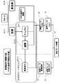
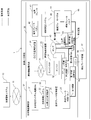
図1に示す自律管制システム10は、鉱山などの作業現場で作業を行う複数台の自律走行車両1や有人車両(図示せず)からなる作業機械の作業内容や走行位置、走行状態を管理し、作業現場における作業工程にあわせて、自律走行車両1や有人車両に対して今後行うべき行動を指示する役割を担っているシステムである。管制オペレータが、自律管制システム10の指令等を無線通信ネットワーク11を介して、複数台の自律走行車両1や有人車両等に送信している。
自律走行車両1は、オペレータが搭乗して運転操作を行う、所謂有人車両に、自律管制システム10からの管制指示に従って自律走行させるための自律走行システムを搭載する改造(retrofit)を施すことにより、有人車両に自律走行機能を追加した車両である。本実施形態では、自律走行車両の例として鉱山用のダンプトラックを例に挙げて説明するが、本実施形態に係る自律走行車両の種類はダンプトラックに限らず、散水車や航測車であってもよい。
自律走行車両1は、有人車両として備えられた標準機能構成部30と、アドオンする形で搭載された自律機能構成部20とを含んで構成されている。
標準機能構成部30は、イグニッションキーからなるエンジンスイッチ(SW)31、エンジン32、CAN(Control Area Network)車載ネットワーク33、GPSやIMUなどの自己位置推定装置34、ミリ波レーダやLIDARからなる障害物検知装置35、電気ブレーキ41、電気ブレーキペダル42、油圧ポンプ43、機械ブレーキペダル44、標準ブレーキバルブ45、標準車載システム46、油圧ブレーキ装置47、及び作動油を貯留する作動油タンク48、障害物検知装置35、及び自己位置推定装置34を含んで構成される。
一方、自律機能構成部20は、自律走行システム電源スイッチ(SW)21、自律車載システム22及びそれに含まれる自律走行制御装置23、自律ブレーキ制御装置24、及び自律ブレーキ制御バルブ25を含む。
自律車載システム22はCAN33に接続され、CAN33を介して自己位置推定装置34及び障害物検知装置35の検知信号を取得する。自律車載システム22は、これらの検知信号を基に予め定められた走行ルートに自律走行車両1を追従させて走行させるための自律走行制御や、走行ルート上に障害物がある場合の回避動作の実行制御を行う。
自律走行制御装置23は、自律車載システム22の一部に含まれ、上記自律走行制御や回避動作に必要がある場合には、自律ブレーキ制御装置24に対して停止指令や制動指令を出力する。
自律ブレーキ制御装置24は、停止指令や制動指令に応じて自律ブレーキ制御バルブの開閉制御を行う。
油圧ポンプ43と標準ブレーキバルブ45とは第1流路で接続される。また標準ブレーキバルブ45と油圧ブレーキ装置47とは第2流路で接続される。この第2流路上に高圧選択弁50が配置される。
更に油圧ポンプ43と自律ブレーキ制御バルブ25とは第3流路(「第1の供給流路」に相当する)で接続され、自律ブレーキ制御バルブ25と高圧選択弁50とは第4流路で接続される。すなわち、高圧選択弁50を介して標準ブレーキバルブ45から油圧ブレーキ装置47へと圧油が流れる第2流路に、自律ブレーキ制御バルブ25から油圧ブレーキ装置47へと向かう流路が接続される。なお、各流路は油圧配管により構成される。
標準機能構成部30において、オペレータがエンジンSW31を用いてエンジン起動操作を行うと、エンジン32が起動し、エンジン32により油圧ポンプ43が駆動して作動油タンク48から作動油をくみ上げて吐出する。油圧ポンプ43から吐出された圧油は、第1流路を通過して標準ブレーキバルブ45に供給される。ここで図2に示すようにオペレータが機械ブレーキペダル44を踏み込むと(ステップS1/Yes)、その踏込み操作量(踏込量)に応じ開度で標準ブレーキバルブ45が開き、圧油が第2流路を通過して高圧選択弁50へと流入する。
高圧選択弁50は第2流路と第4流路とのうち、流路内の圧力が高い方を開放するので、オペレータが機械ブレーキペダル44を踏み込むと、標準ブレーキバルブ45を経由した圧油が高圧選択弁50に向かって流れ、油圧ブレーキ装置47に供給される(ステップS2)。これにより、オペレータのブレーキ操作により油圧ブレーキ装置47を動作させることができる。
また自律機能構成部20において、油圧ポンプ43が作動油タンク48からくみ上げた作動油は、第3流路を経由して自律ブレーキ制御バルブ25に供給される。自律ブレーキ制御装置24は、自律走行制御装置23からの停止指令又は減速指令に基づいて自律ブレーキ制御バルブ25の開閉制御、即ち開度を決定し、その開度を示すバルブ制御信号を自律ブレーキ制御バルブ25に出力すると(ステップS1/No、ステップS3/Yes)、自律ブレーキ制御バルブ25の開度に応じた量の圧油が第4流路を通過して高圧選択弁50へと流れる。
高圧選択弁50は、第4流路の圧力が第2流路の圧力よりも高ければ第4流路からの圧油が油圧ブレーキ装置47に流れる方向に流路を切り替える。これにより、自律車載システム22が停止指令又は減速指令を出力すると、自律ブレーキ制御バルブ25が開き、圧油が高圧選択弁50を介して油圧ブレーキ装置47に供給され、制動動作が行われる(ステップS4)。機械ブレーキペダルが踏み込まれず(ステップS1/No)、自律走行制御装置が停止指令を出力しない場合は(ステップS3/No)、油圧ブレーキ装置47は動作することなく処理を終了する。
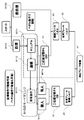
次に図3、図4を参照して自律走行車両1の作業モードについて説明する。図3は、第1実施形態に係る自律走行車両のブレーキ制御装置の作動説明図(1)である。図4は、第1実施形態に係る自律走行車両のブレーキ制御装置の作動説明図(2)である。
自律走行車両1は、自律管制システム10からの指令によって、基本的に無人で自律的に、鉱山作業現場で土砂運搬作業(走行、旋回、停止等の)を行う。しかし、自律走行車両1が自律的に走行する状態においても、必ずしも無人で走行するわけではなく、地図データを作成するための走行、自律走行時の稼働データ測定のための走行、事前確認試験のための走行、メンテナンスや給油作業時の走行等々、有人で走行するシーンがある。そのため、単純に、有人運転と自律走行運転を切り替えると不安全な状況に陥る場合がある。
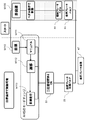
それらに対応するために、図3に示すように自律走行車両1には大きくは非自律モード(non-autonomous mode)M100及び自律モード(autonomous mode)M110がある。
非自律モードM100は、自律走行車両1の自律走行システム電源SW21が入っていない状態で、人が操作して作動させる通常の有人操作モードである。
自律モードM110は、自律走行システム電源SW21が入っている状態で、その中には、マニュアルモード(Manual mode) M111、遷移モードM112、及び自律走行モードM113の3つのモードが存在する。
自律走行車両1は、停止状態からオペレータがエンジンSW31を入れてエンジン32を起動する。そして、非自律モードM100の状態で立ち上がる。
次に、自律走行システム電源SW21を入れると、自律モードM110に移行し、その自律モードM110の中のマニュアルモードM111の状態で起動する。この状態では、自律走行ができる状態ではない。
その次に、自律走行モードM113に移行する準備段階である遷移モードM112に移行する。遷移モードM112に移行した段階で、オペレータは、自律走行車両1から離れる。オペレータが安全な位置に移動した後に、管理者権限を持った人間(以下「管制オペレータ」という)が自律管制システム10から自律走行モードM113への移行を行う。この状態になって始めて自律走行車両1は、自律的に動作することができる。
また、自律走行モードM113において、オペレータが運転席に乗る場合が存在する。その際は、オペレータが自律走行車両1に搭乗した状態で、管制オペレータと連絡を取り合い、自律管制システム10から自律走行モードM113への移行を行ってもらい、自律的に動作することができる。
以上のように、自律走行車両では、4つの作動モードを持ち、様々なシーンに対応できるようにしている。
自律走行車両1といっても、上記の4つの作業モード全てにおいて、自律走行車両1に搭乗したオペレータが操作する可能性があるので、全ての作業モードにおいてオペレータがブレーキ操作を行えるようにしておく必要がある。
非自律モードM100では、自律走行車両1の自律機能構成部20の自律走行システム電源SW21が入っていないため、自律車載システム22、自律走行制御装置23及び自律ブレーキ制御装置24が起動しておらず、自律管制システム10からの指令を受け付けることができない。そのため、オペレータが機械ブレーキペダル44を操作し、標準ブレーキバルブ45から高圧選択弁50を経由して油圧ブレーキ装置47に圧油が送られ、自律走行車両1を停止させる。
自律モードM110は、マニュアルモードM111、遷移モードM112、自律走行モードM113の3つのモードが存在し、これは、自律のモードチェンジで、この順番でモードを変更することで自律走行が可能となる。そして、そのモードチェンジを運転席で行う場合(図3)と地上で行う場合(図4)がある。
運転席で行う場合(図1、3)は、自律走行システム電源SW21を入れると、自律モードM110の中のマニュアルモードM111の状態で起動し遷移モードM112に移行する。この2つの状態では、自律走行ができる状態ではないので、オペレータが機械ブレーキペダル44を操作して、標準ブレーキバルブ45を動かし、油圧ブレーキ装置47を作動させ、自律走行車両1を停止させる。そして、自律走行モードM113に移行すると、自律ブレーキ制御が可能となる。
ここで、遷移モードM112に移行後、人が自律走行車両1から離れる場合と自律走行車両1に搭乗したままの場合とがある。
オペレータが自律走行車両1から離れる場合は、オペレータが安全な位置に移動した後に、管制オペレータが自律管制システム10から自律走行モードM113への移行を行う。この状態で自律走行車両1は、無人で自律的に動作し、自律ブレーキ制御装置24が、自律ブレーキ制御バルブ25を開いて、油圧ブレーキ装置47を作動させ、自律走行車両1を停止させる。
オペレータが運転席に乗ったままの場合は、管制オペレータに連絡して、自律管制システム10から自律走行モードM113への移行を行う。この状態で自律走行車両1は、有人、即ち運転席にオペレータが搭乗しているが自律的に動作する。その際は、自律的にブレーキを作動させ、自律走行車両1を停止させることもできるし、オペレータが機械ブレーキペダル44を操作して、自律走行車両1を停止させることもできる。
地上で行う場合(図1、図4)は、自律走行車両1の下部に設置された起動装置(図示せず)で、自律のモードチェンジを行う。そして、自律走行システム電源SW21を入れると、自律モードM110の中のマニュアルモードM111の状態で起動し、遷移モードM112に移行する。この状態では、運転席にオペレータが搭乗していないことから機械ブレーキペダル44を操作して、車両を停止させることはできないため、遠隔停止を用いて、自律的にブレーキを作動させ、自律走行車両1を停止させる。自律管制システム10は、自律走行制御装置23に遠隔停止信号を送信し、自律走行制御装置23から自律ブレーキ制御装置24に停止指令を出し、自律ブレーキ制御装置24がバルブ制御信号を自律ブレーキ制御バルブ25に出力してバルブを開く。これにより、油圧ポンプ43からの圧油が高圧選択弁50を経由して油圧ブレーキ装置47に送られ、自律走行車両1を停止させる。
次に、自律走行モードM113に移行すると、自律ブレーキ制御が可能となる。ここで、遷移モードM112に移行後、オペレータが自律走行車両1から離れ、安全な位置に移動した後に、管制オペレータが自律管制システム10から自律走行モードM113への移行を行う。この状態で自律走行車両1は、無人で自律的に動作し、自律ブレーキ制御装置24が、自律ブレーキ制御バルブ25を開いて、油圧ブレーキ装置47を作動させ、自律走行車両1を停止させる。
本実施形態における自律走行車両1は、高圧選択弁50を介して標準機能構成部30と自律機能構成部20とは油圧配管を介して連結される。そして、自律走行車両1に搭乗したオペレータの操作によるブレーキ動作(操作系)と、自律機能構成部20によるブレーキ動作(制御系)とを自律走行車両1に搭載させ、自律機能構成部20が油圧ブレーキ装置47を動作させていないときでもオペレータが機械ブレーキペダル44を踏み込むことで油圧ブレーキ装置47を動作させることができる。これにより、油圧ブレーキ装置47を動作させる際に、操作系のブレーキ動作を制御系のブレーキ動作よりも優先させることができる。
また本実施形態によれば、自律走行車両の全ての作動モード状態において、ブレーキペダル操作でブレーキ装置を作動させることができるため、自律管制システム10からの指示に従って、走行、旋回、停止等の動作を自律的に行う自律走行モードにおいて、人が搭乗して運行する状況の場合に、人の判断で、ブレーキ操作を行うことが可能となり、安全に車両を停止させることができる。その他の作動モードである非自律モード、自律モードのマニュアルモードと、人が搭乗して操作する自律走行モードに移行する場合の遷移モードにおいては、人が搭乗して操作するので、ブレーキ操作して安全に停止することがもちろん可能である。
また、本実施形態に係る自律走行車両1は、標準機能構成部30のみを搭載した標準機の第2流路(標準ブレーキバルブ45から油圧ブレーキ装置47に圧油を供給する流路)上に高圧選択弁50を後付し、これを介して自律ブレーキ制御バルブ25を油圧ブレーキ装置47に接続すると共に自律ブレーキ制御バルブ25の上流側を油圧ポンプ43に接続することで、自律車載システム22、自律走行制御装置23、自律ブレーキ制御装置24、及び自律ブレーキ制御バルブ25を含む自律走行システムを用いて標準機に搭載された油圧ブレーキ装置47を動作させることができる。すなわち、標準機に自律機能構成部20を後付することができる。これにより、既に鉱山で稼働している標準機を自律走行車両に改修することができる。
<第2実施形態>
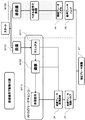
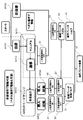
図5は、第2実施形態に係る自律走行車両の概略構成を示す図である。
図5は、第2実施形態に係る自律走行車両の概略構成を示す図である。
第2実施形態に係るダンプトラックが第1実施形態と異なる点は、油圧ポンプ43と自律ブレーキ制御バルブ25とをつなぐ油圧配管からなる第3流路上に二位置切替弁A51(第1の二位置切替弁に相当する)を配置し、二位置切替弁A51から供給される圧油が流れる方向の切替操作を行う第1手動切替SW52(第1の手動操作装置に相当する)を備える点である。二位置切替弁A51の上流側は油圧ポンプ43に接続され、一方の下流側の排出口は自律ブレーキ制御バルブ25に接続され、他方の下流側の排出口は作動油タンク48に接続される。この作動油タンク48に接続する流路を第5流路(「第1の排出流路」に相当する)という。つまり、二位置切替弁A51は、油圧ポンプ43からの圧油を自律ブレーキ制御バルブ25に流すか作動油タンク48に戻すかを切り替える弁である。流路の切替は、自律ブレーキ制御装置24による制御ではなく、オペレータが第1手動切替SW52を手動で操作することにより行う。これにより、自律制御系がオペレータの意思に反して二位置切替弁A51を切り替えることを抑止する。
二位置切替弁A51は油圧ポンプ43からの圧油を自律ブレーキ制御バルブ25に流す流路と、油圧ポンプ43からの圧油を作動油タンク48に流す流路(第5流路)とに切り替える。前者の場合は、自律管制システム10から自律走行制御装置23を経由して自律ブレーキ制御装置24に停止指令が来ると、自律ブレーキ制御バルブ25が開いて油圧ポンプ43からの圧油が高圧選択弁50を介して油圧ブレーキ装置47に送られ、自律走行車両1が停止する。
後者の場合は、油圧ポンプ43からの圧油が作動油タンク48に流れるので、自律ブレーキ制御バルブ25には圧油は流れない。そのため自律ブレーキ制御バルブ25からの圧油が高圧選択弁50を介して油圧ブレーキ装置47に送られないため、自律走行制御装置23は自律走行車両1を停止させることができない。つまり、自律走行車両1において、二位置切替弁A38を切り替えることによって、自律制御ブレーキを無効化、即ち、積極的に作動させないようにすることができる。
ここで、本実施形態におけるブレーキ制御装置の動作概要について図5,6,7を用いて説明する。非自律モードM100は、第1実施形態と同様なので説明は省略する。図6は第2実施形態に係る自律走行車両のブレーキ制御装置の作動説明図(1)である。図7は、第2実施形態に係る自律走行車両のブレーキ制御装置の作動説明図(2)である。
自律モードM110は、モードチェンジをマニュアルモードM111、遷移モードM112、自律走行モードM113の順番で変更することで自律走行が可能となる。そして、そのモードチェンジを運転席で行う場合(図6)と地上で行う場合(図7)とがある。
運転席で行う場合(図5、6)は、自律走行システム電源SW21を入れると、マニュアルモードM111で起動し、次に遷移モードM112に移行する。この2つの状態では、自律走行ができる状態ではないので、オペレータが機械ブレーキペダル44を操作して、標準ブレーキバルブ45を動かし、油圧ブレーキ装置47を作動させ、自律走行車両1を停止させる。その際に、二位置切替弁A51をOFF、つまり二位置切替弁A51を油圧ポンプ43からの圧油を作動油タンク48に流す方向(第5流路)に切り替えることにより、自律ブレーキ制御バルブ25に油圧ポンプ43からの圧油が供給されないので、自律ブレーキ制御を作動できない状態にする。そして、自律走行モードM113に移行すると、自律ブレーキ制御が可能となる。
ここで、遷移モードM112に移行後、オペレータが自律走行車両1から離れる場合と自律走行車両1に搭乗したままの場合とがある。
オペレータが離れる場合は、第1手動切替SW52をON、つまり二位置切替弁A51を油圧ポンプ43からの圧油が自律ブレーキ制御バルブ25に流れる方向(第3流路のうち、二位置切替弁A51よりも下流側の流路)に切り替えてから安全な位置に移動した後に、管制オペレータが自律管制システム10から自律走行モードM113への移行を行う。
この無人状態M115で自律走行車両1は、無人で自律的に動作し、自律ブレーキ制御装置24が、自律ブレーキ制御バルブ25を開いて、油圧ブレーキ装置47を作動させ、自律走行車両1を停止させる。その際に、二位置切替弁A51をONなので、自律ブレーキ制御が可能となる。そのあとの自律ブレーキ制御の作動は、第1実施形態と同様なので説明は省略する。
オペレータが運転席に乗ったままの場合は、管制オペレータに連絡して、自律管制システム10から自律走行モードM113への移行を行う。この有人状態M114では、自律走行車両1は、有人ではあるが自律的に動作する。その際は、二位置切替弁A51をON、つまり二位置切替弁A51を、油圧ポンプ43からの圧油を自律ブレーキ制御バルブ25に流す方向(第3流路のうち、二位置切替弁A51よりも下流側の流路)に切り替えて帰ることにより、自律的にブレーキを作動させ、自律走行車両1を停止させることもできるし、オペレータが機械ブレーキペダル44を操作して、自律走行車両1を停止させることもできる。
地上で行う場合(図5、7)は、自律走行車両1の下部に設置された起動装置(図示せず)で、自律のモードチェンジを行う。自律走行システム電源SW21を入れると、マニュアルモードM111で起動し、次に遷移モードM112に移行する。この2つの状態では、オペレータが運転席に乗っていないので、機械ブレーキペダル44を操作して、自律走行車両1を停止させることはできない。そこで、自律管制システム10を用いて、自律的にブレーキを作動させ、自律走行車両1を停止させる。その際に、二位置切替弁A51をON、つまり二位置切替弁A51を、油圧ポンプ43からの圧油を自律ブレーキ制御バルブ25に流す方向(第3流路のうち、二位置切替弁A51よりも下流側の流路)に切り替えることにより、自律ブレーキ制御が可能となる。そのあとの自律ブレーキ制御の作動は、第1実施形態と同様なので説明は省略する。
遷移モードM112に移行後、オペレータが第1手動切替SW52をONに操作してからオペレータが自律走行車両1から離れ、安全な位置に移動した後に、管制オペレータが自律管制システム10から自律走行モードM113への移行を行う。この状態で自律走行車両1は、無人で自律的に動作することが可能となる。そして、自律ブレーキ制御装置24が、自律ブレーキ制御バルブ25を開いて、油圧ブレーキ装置47を作動させ、自律走行車両1を停止させる。その際に、二位置切替弁A51をON、つまり二位置切替弁A51を油圧ポンプ43からの圧油が自律ブレーキ制御バルブ25に流す方向に切り替えることにより、自律ブレーキ制御が可能となる。そのあとの作動は、第1実施形態と同様なので説明は省略する。
本実施形態におけるブレーキ制御装置は、第1実施形態の構成に加え、油圧ポンプ43と自律ブレーキ制御バルブ25をつなぐ油圧配管(第3流路)に二位置切替弁A51を追加し、一方の下流側を作動油タンク48に接続する第5流路を増設する。この二位置切替弁A51を切り替えることによって、自律ブレーキ制御の機能のON/OFFを切り替えることができる。
本実施形態によれば、自律走行車両においてオペレータが操作する場合、自律的(自動的)にブレーキ装置を作動させるシステムを無効にできるため、自律走行システムの電源が入っている状態ではあるが、人が操作するモードのマニュアルモードにおいて、自律的(自動的)にブレーキ装置を作動して、不安全な状態になることを防止できる。特にマニュアルモードは、自律走行システム電源SW21が入っている状態のため、自律機能構成部20へも電源供給されている。よって、自律機能構成部20は起動しているが、二位置切替弁A51が油圧の供給を遮断する遮断弁として機能することで、自動ブレーキを作動させることができない。もちろん、この遮断弁は、非自律モードの状態でも有効で、自動ブレーキ側の油圧供給を絶つことができるため、人の意に反して、ブレーキが作動して、不安全な状態になることを防止することができる。
<第3実施形態>
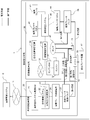
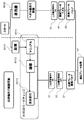
図8は、第3実施形態に係る自律走行車両の概略構成を示す図である。
図8は、第3実施形態に係る自律走行車両の概略構成を示す図である。
第3実施形態に係る自律走行車両1が第2実施形態と異なる部分は、油圧ポンプ43と標準ブレーキバルブ45とをつなぐ油圧配管からなる第1流路(「第2の供給流路」に相当する)上に、二位置切替弁B53(第2の二位置切替弁に相当する)を配置し、二位置切替弁B53から供給される圧油が流れる方向の切替操作を行う第2手動切替SW54(第2の手動操作装置に相当する)を備える点である。
この二位置切替弁B53は、油圧ポンプ43からの圧油を標準ブレーキバルブ45に流すか作動油タンク48に戻すかを切り替える弁である。流路の切替は、自律ブレーキ制御装置24による制御ではなく、オペレータが第2手動切替SW54を手動で操作することにより行う。これにより、自律制御系がオペレータの意思に反して二位置切替弁B53を切り替えることを抑止する。
二位置切替弁B53が油圧ポンプ43からの圧油を標準ブレーキバルブ45に流す流路と、油圧ポンプ43からの圧油を作動油タンク48に流す第6流路(「第2の排出流路」に相当する)に切り替える。前者の場合は、機械ブレーキペダル44の操作により、油圧ポンプ43からの圧油が高圧選択弁50を介して油圧ブレーキ装置47に送られ、自律走行車両1が停止する。
後者の場合は、油圧ポンプ43からの圧油が作動油タンク48に流れるので、標準ブレーキバルブ45には圧油は流れない。そのため、機械ブレーキペダル44を操作して油圧ブレーキ装置47を作動させて、自律走行車両1を停止させることができない。つまり、自律走行車両1において、二位置切替弁B53を切り替えることによって、オペレータが機械ブレーキペダル44を使って油圧ブレーキ装置47を作動できないようにすることを選択できる構成としている。
ここで、本実施形態におけるブレーキ制御装置の動作概要について図8、9、10を用いて説明する。図9は、第3実施形態に係る自律走行車両のブレーキ制御装置の作動説明図(1)である。図10は、第3実施形態に係る自律走行車両のブレーキ制御装置の作動説明図(2)である。非自律モードM100は、第1、2実施形態と同様なので説明は省略する。
自律モードM110は、モードチェンジをマニュアルモードM111、遷移モードM112、自律走行モードM113の順番で変更することで自律走行が可能となる。そして、そのモードチェンジを運転席で行う場合(図9)と地上で行う場合(図10)とがある。
運転席で行う場合(図8、9)は、自律走行システム電源SW21を入れると、マニュアルモードM111で起動し、次に遷移モードM112に移行する。この2つの状態では、自律走行ができる状態ではないので、オペレータが機械ブレーキペダル44を操作して、標準ブレーキバルブ45を動かし、油圧ブレーキ装置47を作動させ、自律走行車両1を停止させる。その際に、二位置切替弁A51をOFF、つまり二位置切替弁A51を油圧ポンプ43からの圧油を作動油タンク48に流す方向に切り替えることと、二位置切替弁B53をON、つまり二位置切替弁B53を油圧ポンプ43からの圧油が標準ブレーキバルブ45に流す方向(第1流路における二位置切替弁B53より下流側の流路)に切り替えることにより、自律ブレーキ制御バルブ25に圧油が供給されないので、自律ブレーキ制御を作動できない状態にすると共に機械ブレーキペダル44を操作して油圧ブレーキ装置が作動する状態にする。そして、次に、自律走行モードM113に移行すると、自律走行車両1は、無人で自律的に動作が可能となる。
ここで、遷移モードM112に移行後、オペレータが自律走行車両1から離れる場合と自律走行車両1に搭乗したままの場合とがある。
オペレータが離れる場合は、第1手動切替SW52をON、つまり二位置切替弁A51を油圧ポンプ43からの圧油が自律ブレーキ制御バルブ25に流す方向(第3流路のうち、二位置切替弁A51よりも下流側の流路)に切り替えると共に、第2手動切替SW54をOFF、つまり二位置切替弁B53を油圧ポンプ43からの圧油が作動油タンク48に流れる方向(第6流路)に切り替えてから安全な位置に移動した後に、管制オペレータが自律管制システム10から自律走行モードM113への移行を行う。
この無人状態M115で自律走行車両1は、無人で自律的に動作し、自律ブレーキ制御装置24が、自律ブレーキ制御バルブ25を開いて、油圧ブレーキ装置47を作動させ、自律走行車両1を停止させる。その際に、二位置切替弁A51がON、つまり二位置切替弁A51を油圧ポンプ43からの圧油を自律ブレーキ制御バルブ25に流す流路に切り替えることと、二位置切替弁B53をOFF、つまり二位置切替弁B53を油圧ポンプ43からの圧油が作動油タンク48に戻る第6流路に切り替えることとにより、自律ブレーキ制御のみが可能となる。そのあとの自律ブレーキ制御の作動は、第1の実施形態と同様なので説明は省略する。
オペレータが運転席に乗ったままの場合は、管制オペレータが自律管制システム10から自律走行モードM113への移行を行う。この有人状態M114で自律走行車両1は、有人ではあるが自律的に動作が可能である。この状態では、二位置切替弁A51をON、つまり二位置切替弁A51を油圧ポンプ43からの圧油を自律ブレーキ制御バルブ25に流す流路に切り替えることと、二位置切替弁B53をON、つまり二位置切替弁B53を油圧ポンプ43からの圧油を標準ブレーキバルブに45に流す流路に切り替えることにより、自律ブレーキ制御と機械ブレーキペダル44操作のブレーキ制御との両方が可能となる。
地上で行う場合(図8、10)は、自律走行車両1の下部に設置された起動装置(図示せず)で、自律のモードチェンジを行う。自律走行システム電源SW21を入れると、マニュアルモードM111で起動し、次に遷移モードM112に移行する。この2つの状態では、オペレータが運転席に乗っていないので、機械ブレーキペダル44を操作して、自律走行車両1を停止させることはできない。そこで、自律管制システム10を用いて、自律的にブレーキを作動させ、自律走行車両1を停止させる。その際に、二位置切替弁A51をON、つまり二位置切替弁A51を油圧ポンプ43からの圧油を自律ブレーキ制御バルブ25に流す方向に切り替えることと、二位置切替弁B53をOFF、つまり二位置切替弁B53を油圧ポンプ43からの圧油を作動油タンク48に戻す流路に切り替えることとにより、自律ブレーキ制御のみが可能となる。そのあとの自律ブレーキ制御の作動は、第1の実施形態と同様なので説明は省略する。
遷移モードM112に移行後、オペレータが第1手動切替SW52をON、第2手動切替SW54をOFFに操作してから自律走行車両1から離れ、安全な位置に移動した後に、管制オペレータが自律管制システム10から自律走行モードM113への移行を行う。この状態で自律走行車両1は、無人で自律的に動作することが可能となる。そして、自律ブレーキ制御により自律走行車両1を停止させる。その際に、二位置切替弁A51をON、かつ二位置切替弁B53をOFFに切り替えることにより、自律ブレーキ制御のみが可能となる。そのあとのブレーキ制御の作動は、第1の実施形態と同様なので説明は省略する。
本実施形態におけるブレーキ制御装置は、第2実施形態に加え、油圧ポンプ43と標準ブレーキバルブ45とをつなぐ油圧配管(第1流路)に二位置切替弁B53を追加する。この二位置切替弁B53を切り替えることによって、標準ブレーキバルブの機能のON/OFFを切り替えることができる。
本実施形態によれば、自律走行車両(自律走行ダンプトラック)において、人が運転しない(無人)の場合、ブレーキペダル操作でブレーキ装置を作動させることができないように構成としたため、自律管制システム10からの指示に従って、走行、旋回、停止等の動作を自律的に行う自律走行モードにおいて、人が搭乗しない無人運転の状況の場合に、何らかの要因で(例えば、ブレーキペダルに何か物が落ちてきて、ペダルを押す等)、ブレーキペダルが操作され、自律管制システム10からの指示等とは異なるブレーキ動作が行われて、不安全な状況になることを防止できる。
つまり、自律走行車両は、全ての作動モード状態において、ブレーキペダル操作でブレーキ装置を作動させることができる構成となっているため、何らかの要因で、ブレーキペダルが操作され、急停止することによって、かえって不安全な状態になる可能性がある。そこで、本実施形態のように、ブレーキペダルで動作する標準機能側の油圧回路への圧油の供給を遮断する遮断弁として機能する二位置切替弁B53を設置することにより、ペダル操作で作動するブレーキを無効化し、管制の指令に反して、ブレーキが作動して不安全な状態になることを防止することができる。
上記実施形態は本発明を限定するものではなく、本発明の趣旨を逸脱しない範囲での変更態様は、本発明に含まれるものとする。例えば、第3実施形態は、第2実施形態に二位置切替弁B53を追加する構成として説明したが、第1実施形態に二位置切替弁B53を追加する構成、即ち二位置切替弁A51はなく二位置切替弁B53がある態様であってもよい。
また、本実施形態は、標準機にレトロフィットで自律機能部分を改修して自律走行車両を製造する例を説明したが、工場出荷時から標準機能と自律走行機能とを搭載した自律走行車両を製造する場合にも、本発明を適用することができる。
上記自律管制システム10は、管制コントローラからなる管制サーバ(図示せず)と、自律走行コントローラにより構成される自律走行制御装置23とを無線通信回線を介して通信接続して構成される。また、自律ブレーキ制御装置24は、自律走行制御装置23とは異なるブレーキコントローラにより構成されてもよい。更に、自律走行制御装置23及び自律ブレーキ制御装置24は、其々の機能を実現するプログラムを実行する一つのコントローラにより構成されてもよい。ここでいうコントローラとは、CPU(Central Processing Unit)とメモリやストレージ、例えばRAM(Random Access Memory)、ROM(Read Only Memory)、HDD(Hard Disk Drive)とがバスを介して接続されたコンピュータ(ハードウェア)であってもよいし、各機能に特化した集積回路を用いて構成されたコンピュータであってもよい。
第1手動切替SW52(第1の手動操作装置に相当)及び第2手動切替SW54(第2の手動操作装置に相当)の其々は、流路内を開閉して作動油が流れる方向を切替えるレバーにより構成されてもよい。更に第1手動切替SW52及び第2手動切替SW54の其々は、流路の切替を行うハードボタンや、流路の切替操作を行う流路制御コントローラに対して切替え指示を入力する入力装置、ソフトウェアボタン等からなるスイッチにより構成される。
1:自律走行車両、10:自律管制システム、20:自律機能構成部、25:自律ブレーキ制御バルブ、30:標準機能構成部、45:標準ブレーキバルブ、47:油圧ブレーキ装置、50:高圧選択弁、51:二位置切替弁A、53:二位置切替弁B
Claims (4)
- エンジンと、作動油を貯留する作動油タンクと、前記エンジンにより駆動され前記作動油タンク内の作動油を圧油として吐出する油圧ポンプと、前記油圧ポンプから吐出された圧油が供給される標準ブレーキバルブと、前記標準ブレーキバルブを開閉させるブレーキペダルと、前記標準ブレーキバルブから供給される圧油で動作する油圧ブレーキ装置と、を備える作業機械であって、
前記油圧ポンプから吐出された圧油が供給される自律ブレーキ制御バルブと、
前記油圧ポンプから前記自律ブレーキ制御バルブに圧油を供給する第1の供給流路と、
前記油圧ポンプから前記標準ブレーキバルブに圧油を供給する第2の供給流路と、
前記標準ブレーキバルブから前記油圧ブレーキ装置に圧油を供給する流路上に設けられた高圧選択弁と、
前記自律ブレーキ制御バルブと前記高圧選択弁とを接続する流路と、
前記作業機械を自律走行させるための制御を実行する自律走行コントローラからなる自律走行制御装置と、
前記自律走行制御装置からの制動指令に応じて前記自律ブレーキ制御バルブの開閉制御を行うブレーキコントローラからなる自律ブレーキ制御装置と、を備え、
前記標準ブレーキバルブから供給される圧油及び前記自律ブレーキ制御バルブから供給される圧油のうち、より圧力が高い圧油が前記高圧選択弁から前記油圧ブレーキ装置に供給される、
ことを特徴とする作業機械。 - 請求項1に記載の作業機械において、
前記第1の供給流路の流路上に設けられた第1の二位置切替弁と、
前記作業機械のオペレータが、前記第1の二位置切替弁から供給される圧油が流れる方向の切替操作を行うレバー又はスイッチにより構成された第1の手動操作装置と、を更に備え、
前記第1の二位置切替弁の上流側は前記第1の供給流路を介して前記油圧ポンプに接続され、前記第1の二位置切替弁の下流側の一方の排出口は前記第1の供給流路を介して前記自律ブレーキ制御バルブに接続され、前記第1の二位置切替弁の下流側の他方の排出口は第1の排出流路を介して前記作動油タンクに接続される、
ことを特徴とする作業機械。 - 請求項1又は2に記載の作業機械において、
前記第2の供給流路の流路上に設けられた第2の二位置切替弁と、
前記作業機械のオペレータが、前記第2の二位置切替弁から供給される圧油が流れる方向の切替操作を行うレバー又はスイッチにより構成された第2の手動操作装置と、を更に備え、
前記第2の二位置切替弁の上流側は前記第2の供給流路を介して前記油圧ポンプに接続され、前記第2の二位置切替弁の下流側の一方の排出口は前記第2の供給流路を介して前記標準ブレーキバルブに接続され、前記第2の二位置切替弁の下流側の他方の排出口は第2の排出流路を介して前記作動油タンクに接続される、
ことを特徴とする作業機械。 - エンジンと、作動油を貯留する作動油タンクと、前記エンジンにより駆動され前記作動油タンク内の作動油を圧油として吐出する油圧ポンプと、前記油圧ポンプから吐出された圧油が供給される標準ブレーキバルブと、前記標準ブレーキバルブを開閉させるブレーキペダルと、前記標準ブレーキバルブから供給される圧油で動作する油圧ブレーキ装置と、前記標準ブレーキバルブから前記油圧ブレーキ装置に圧油を供給する流路上に設けられた高圧選択弁と、前記油圧ポンプから吐出された圧油が供給される自律ブレーキ制御バルブと、前記自律ブレーキ制御バルブから前記高圧選択弁に圧油を供給する流路と、作業機械の自律走行制御を実行する自律走行コントローラからなる自律走行制御装置と、前記自律走行制御装置からの制動指令に応じて前記自律ブレーキ制御バルブの開閉制御を行うブレーキコントローラからなる自律ブレーキ制御装置と、を備える作業機械の制動方法であって、
前記ブレーキペダルが踏込み操作を受け付けるステップと、
前記踏込み操作に応じて前記標準ブレーキバルブが開き、前記標準ブレーキバルブから前記高圧選択弁に向かって圧油が流れ、前記標準ブレーキバルブを経由した圧油が前記油圧ブレーキ装置に供給される方向に、前記高圧選択弁が流路を切り替えるステップと、
前記標準ブレーキバルブを経由した圧油が前記油圧ブレーキ装置に供給されて前記油圧ブレーキ装置が動作するステップと、
前記自律走行制御装置からの制動指令を前記自律ブレーキ制御装置が取得するステップと、
前記自律ブレーキ制御装置が前記自律ブレーキ制御バルブを開くためのバルブ制御信号を出力するステップと、
前記バルブ制御信号に応じて前記自律ブレーキ制御バルブが開き、前記自律ブレーキ制御バルブから前記高圧選択弁に向かって圧油が流れ、前記自律ブレーキ制御バルブを経由した圧油が前記油圧ブレーキ装置に供給される方向に、前記高圧選択弁が流路を切り替えるステップと、
前記自律ブレーキ制御バルブを経由した圧油が前記油圧ブレーキ装置に供給されて前記油圧ブレーキ装置が動作するステップと、を含むことを特徴とする作業機械の制動方法。
Priority Applications (3)
| Application Number | Priority Date | Filing Date | Title |
|---|---|---|---|
| US16/329,390 US11104316B2 (en) | 2017-03-30 | 2018-03-05 | Work machine and braking method for work machine |
| EP18775703.4A EP3492326B1 (en) | 2017-03-30 | 2018-03-05 | Work machine and method for braking work machine |
| CN201880002992.8A CN109562753B (zh) | 2017-03-30 | 2018-03-05 | 作业机械及作业机械的制动方法 |
Applications Claiming Priority (2)
| Application Number | Priority Date | Filing Date | Title |
|---|---|---|---|
| JP2017-068039 | 2017-03-30 | ||
| JP2017068039A JP6693904B2 (ja) | 2017-03-30 | 2017-03-30 | 作業機械及び作業機械の制動方法 |
Publications (1)
| Publication Number | Publication Date |
|---|---|
| WO2018180262A1 true WO2018180262A1 (ja) | 2018-10-04 |
Family
ID=63675527
Family Applications (1)
| Application Number | Title | Priority Date | Filing Date |
|---|---|---|---|
| PCT/JP2018/008429 WO2018180262A1 (ja) | 2017-03-30 | 2018-03-05 | 作業機械及び作業機械の制動方法 |
Country Status (5)
| Country | Link |
|---|---|
| US (1) | US11104316B2 (ja) |
| EP (1) | EP3492326B1 (ja) |
| JP (1) | JP6693904B2 (ja) |
| CN (1) | CN109562753B (ja) |
| WO (1) | WO2018180262A1 (ja) |
Families Citing this family (2)
| Publication number | Priority date | Publication date | Assignee | Title |
|---|---|---|---|---|
| GB2598967B (en) * | 2020-09-22 | 2022-10-05 | Caterpillar Sarl | Brake system |
| JP2022098359A (ja) * | 2020-12-21 | 2022-07-01 | パナソニックIpマネジメント株式会社 | 車両監視方法、車両監視装置及びプログラム |
Citations (2)
| Publication number | Priority date | Publication date | Assignee | Title |
|---|---|---|---|---|
| JP2004230908A (ja) * | 2003-01-28 | 2004-08-19 | Shin Kobe Electric Mach Co Ltd | 自動走行車のドラムブレーキの制御方式 |
| JP2012144255A (ja) * | 2009-01-08 | 2012-08-02 | Komatsu Ltd | トラクションコントロール装置 |
Family Cites Families (15)
| Publication number | Priority date | Publication date | Assignee | Title |
|---|---|---|---|---|
| JP3891467B2 (ja) * | 2000-09-12 | 2007-03-14 | 本田技研工業株式会社 | ブレーキ液圧保持装置 |
| JP2004230980A (ja) * | 2003-01-29 | 2004-08-19 | Advics:Kk | 車両用液圧ブレーキ装置 |
| JP2006044620A (ja) | 2004-08-02 | 2006-02-16 | Yamaha Motor Co Ltd | 有人無人運転切替走行車両 |
| JP5779110B2 (ja) * | 2012-01-17 | 2015-09-16 | 日立建機株式会社 | ホイール式作業車両の油圧制御装置 |
| EP2902863B1 (en) * | 2012-09-28 | 2019-07-03 | Hitachi, Ltd. | Autonomous moving apparatus |
| DE102012020818A1 (de) * | 2012-10-23 | 2014-04-24 | Liebherr-Hydraulikbagger Gmbh | Bremsvorrichtung für Arbeitsmaschinen und Verfahren zum Betätigen der Bremsvorrichtung |
| DE102013224870A1 (de) * | 2013-03-05 | 2014-09-11 | Continental Teves Ag & Co. Ohg | Bremsbetätigungseinheit |
| JP6111179B2 (ja) * | 2013-10-22 | 2017-04-05 | 日立建機株式会社 | ダンプトラックの自律走行システム |
| DE102014105163A1 (de) * | 2014-04-11 | 2015-10-15 | Claas Selbstfahrende Erntemaschinen Gmbh | Selbstfahrende Erntemaschine |
| EP3203340A4 (en) * | 2014-09-30 | 2018-06-13 | Hitachi Construction Machinery Co., Ltd. | Delivery vehicle |
| EP3118703B1 (en) * | 2015-07-13 | 2018-05-23 | Volvo Car Corporation | Safety stoppage device and method for safety stoppage of an autonomous vehicle |
| EP3015331B1 (en) * | 2015-10-05 | 2020-12-02 | Komatsu Ltd. | Work vehicle and work vehicle control method |
| JP6650242B2 (ja) * | 2015-10-16 | 2020-02-19 | 日立オートモティブシステムズ株式会社 | 自動運転システム、自動運転制御方法、データecuおよび自動運転ecu |
| CN206012579U (zh) * | 2016-08-31 | 2017-03-15 | 卡特彼勒(青州)有限公司 | 工程车辆及其驻车制动液压系统 |
| DE102016116861A1 (de) * | 2016-09-08 | 2018-03-08 | Knorr-Bremse Systeme für Nutzfahrzeuge GmbH | System zum fahrerlosen Operieren von Nutzfahrzeugen |
-
2017
- 2017-03-30 JP JP2017068039A patent/JP6693904B2/ja active Active
-
2018
- 2018-03-05 CN CN201880002992.8A patent/CN109562753B/zh active Active
- 2018-03-05 US US16/329,390 patent/US11104316B2/en active Active
- 2018-03-05 EP EP18775703.4A patent/EP3492326B1/en active Active
- 2018-03-05 WO PCT/JP2018/008429 patent/WO2018180262A1/ja unknown
Patent Citations (2)
| Publication number | Priority date | Publication date | Assignee | Title |
|---|---|---|---|---|
| JP2004230908A (ja) * | 2003-01-28 | 2004-08-19 | Shin Kobe Electric Mach Co Ltd | 自動走行車のドラムブレーキの制御方式 |
| JP2012144255A (ja) * | 2009-01-08 | 2012-08-02 | Komatsu Ltd | トラクションコントロール装置 |
Also Published As
| Publication number | Publication date |
|---|---|
| CN109562753B (zh) | 2021-03-16 |
| EP3492326A4 (en) | 2020-03-04 |
| EP3492326B1 (en) | 2020-12-23 |
| EP3492326A1 (en) | 2019-06-05 |
| JP2018167766A (ja) | 2018-11-01 |
| US11104316B2 (en) | 2021-08-31 |
| CN109562753A (zh) | 2019-04-02 |
| JP6693904B2 (ja) | 2020-05-13 |
| US20190217835A1 (en) | 2019-07-18 |
Similar Documents
| Publication | Publication Date | Title |
|---|---|---|
| US7500535B2 (en) | Control device for construction machine | |
| JPH0876846A (ja) | 自律モード・マニュアルモード選択式車両制御システム | |
| US20200139950A1 (en) | System and method for controlling braking functions in an autonomous vehicle | |
| US10753067B2 (en) | Construction machine | |
| CN104554222A (zh) | 机动车 | |
| WO2018180262A1 (ja) | 作業機械及び作業機械の制動方法 | |
| KR102221165B1 (ko) | 건설기계의 안전 장치 및 제어 방법 | |
| JP2019026033A (ja) | ダンプトラックのブレーキシステム | |
| US9145863B2 (en) | System and method for controlling automatic shut-off of an engine | |
| JP2022033867A (ja) | 車両運転制御システム | |
| JP7085493B2 (ja) | 空気圧ブレーキシステム | |
| JP2010163946A (ja) | 作業車両の原動機制御装置 | |
| JP2018070133A (ja) | 駐車ブレーキ装置 | |
| JP2018167766A5 (ja) | ||
| US9592801B2 (en) | Parking brake system using a programmable logic controller and having a towing mode | |
| JP2008018846A (ja) | 産業車両の油圧制御装置 | |
| KR20110073888A (ko) | 건설기계의 안전 운행을 위한 주행 및 작업 장치의 구동 제어 장치 및 그 방법 | |
| US11427175B2 (en) | Vehicle braking systems and methods | |
| JPS62151603A (ja) | 油圧制御回路 | |
| US20150260063A1 (en) | Safety device for preventing working-apparatus operation during regeneration of forklift-truck diesel-exhaust gas after-treatment device | |
| CN214295847U (zh) | 线控底盘运动控制系统 | |
| KR20090120744A (ko) | 휠 굴삭기 주행 제어 장치 | |
| WO2023198281A1 (en) | A control system for controlling a fleet of autonomous vehicles | |
| WO2020158125A1 (ja) | 無人車両の制御システム及び無人車両の制御方法 | |
| KR20220095447A (ko) | 무인차량의 안전성을 위한 감속 다중화 시스템 |
Legal Events
| Date | Code | Title | Description |
|---|---|---|---|
| 121 | Ep: the epo has been informed by wipo that ep was designated in this application |
Ref document number: 18775703 Country of ref document: EP Kind code of ref document: A1 |
|
| ENP | Entry into the national phase |
Ref document number: 2018775703 Country of ref document: EP Effective date: 20190301 |
|
| NENP | Non-entry into the national phase |
Ref country code: DE |