WO2018180252A1 - Treatment method and treatment device - Google Patents
Treatment method and treatment device Download PDFInfo
- Publication number
- WO2018180252A1 WO2018180252A1 PCT/JP2018/008362 JP2018008362W WO2018180252A1 WO 2018180252 A1 WO2018180252 A1 WO 2018180252A1 JP 2018008362 W JP2018008362 W JP 2018008362W WO 2018180252 A1 WO2018180252 A1 WO 2018180252A1
- Authority
- WO
- WIPO (PCT)
- Prior art keywords
- container
- solid matter
- development
- solid
- liquid
- Prior art date
Links
Images


Classifications
-
- G—PHYSICS
- G03—PHOTOGRAPHY; CINEMATOGRAPHY; ANALOGOUS TECHNIQUES USING WAVES OTHER THAN OPTICAL WAVES; ELECTROGRAPHY; HOLOGRAPHY
- G03F—PHOTOMECHANICAL PRODUCTION OF TEXTURED OR PATTERNED SURFACES, e.g. FOR PRINTING, FOR PROCESSING OF SEMICONDUCTOR DEVICES; MATERIALS THEREFOR; ORIGINALS THEREFOR; APPARATUS SPECIALLY ADAPTED THEREFOR
- G03F7/00—Photomechanical, e.g. photolithographic, production of textured or patterned surfaces, e.g. printing surfaces; Materials therefor, e.g. comprising photoresists; Apparatus specially adapted therefor
- G03F7/26—Processing photosensitive materials; Apparatus therefor
- G03F7/30—Imagewise removal using liquid means
- G03F7/3092—Recovery of material; Waste processing
-
- B—PERFORMING OPERATIONS; TRANSPORTING
- B04—CENTRIFUGAL APPARATUS OR MACHINES FOR CARRYING-OUT PHYSICAL OR CHEMICAL PROCESSES
- B04B—CENTRIFUGES
- B04B1/00—Centrifuges with rotary bowls provided with solid jackets for separating predominantly liquid mixtures with or without solid particles
- B04B1/04—Centrifuges with rotary bowls provided with solid jackets for separating predominantly liquid mixtures with or without solid particles with inserted separating walls
-
- B—PERFORMING OPERATIONS; TRANSPORTING
- B04—CENTRIFUGAL APPARATUS OR MACHINES FOR CARRYING-OUT PHYSICAL OR CHEMICAL PROCESSES
- B04B—CENTRIFUGES
- B04B13/00—Control arrangements specially designed for centrifuges; Programme control of centrifuges
-
- B—PERFORMING OPERATIONS; TRANSPORTING
- B04—CENTRIFUGAL APPARATUS OR MACHINES FOR CARRYING-OUT PHYSICAL OR CHEMICAL PROCESSES
- B04B—CENTRIFUGES
- B04B5/00—Other centrifuges
- B04B5/10—Centrifuges combined with other apparatus, e.g. electrostatic separators; Sets or systems of several centrifuges
Definitions
- the present invention relates to a processing method and processing apparatus for a development fatigue solution, and particularly includes a solid matter generated by removing an unexposed portion of a photosensitive resin plate after imagewise exposure by development using a washing solution.
- the present invention relates to a processing method and processing apparatus for developing fatigue fluid.
- Various methods are known as developing methods for printing plates using photosensitive resin plates.
- a development method in which development is performed using an aqueous developer containing water as a main component, the photosensitive resin plate after imagewise exposure is immersed in the aqueous developer, and the unexposed portion is immersed in the aqueous developer with a brush or the like.
- Development is performed by washing out uncured resin and the like.
- the uncured resin or the like is dispersed in the developer. It has been proposed to remove a dispersed uncured resin and reuse the developer in a state where the uncured resin is dispersed.
- the above-mentioned developer is also called a wash-out solution.
- Patent Document 1 describes a method of treating a washing solution containing solid matter generated when developing a photosensitive resin plate after exposure by removing an unexposed portion while being immersed in the washing solution. ing.
- solids having a specific gravity smaller than that of the washing liquid are separated and removed using a centrifugal sedimentation type centrifugal separation process having an inside disk, and the processed liquid obtained by separating and removing solids having a lower specific gravity than the washing liquid is obtained. Further, it is described that it is reused as a washing solution.
- Patent Document 1 solids having a specific gravity smaller than that of the washing liquid are separated and removed by a centrifugal sedimentation type centrifugal separation process having an inside disk.
- Patent Document 1 since the separated washing liquid is collected by the skimming tube, a large amount of solid matter is mixed in the washing liquid due to a change in the amount of the separated solid matter due to the mixing concentration of the solid matter. The solid concentration of the processed washout liquid becomes high.
- An object of the present invention is to provide a processing method and a processing apparatus in which the solid content concentration of the developing fatigue liquid is low and the moisture content of the discharged solid matter is low.
- the present invention provides a development fatigue solution containing a solid matter generated by removing an unexposed portion of a photosensitive resin plate after imagewise exposure by development using a washing solution.
- the second step and the third step there is a step of removing the second solid material from the container, and after the third step, there is a step of removing the first solid material from the container.
- the development fatigue liquid discharged from the container may be reused as a rinse liquid for washing away the residue remaining on the plate surface after the unexposed portion is developed and removed.
- the present invention provides an opening for storing a development fatigue solution containing solid matter generated by removing an unexposed portion of the photosensitive resin plate after imagewise exposure by development using a washing solution.
- a holding member that holds the first solid matter that is rotated, and a container in which the developing fatigue liquid is stored is rotated and centrifuged by the drive unit, and the first solid matter is accumulated on the holding member, and the drive unit Stop the rotation of the container and accumulate on the holding member.
- a control unit that rotates the container again by the drive unit after the development fatigue liquid is discharged from the container in a state where the first solid matter is held
- the restricting member is preferably a disk having an opening
- the holding member is preferably a disk or a disk having an opening. It has a separation membrane that removes solid matter generated by development, and the development fatigue fluid discharged from the container is passed through the separation membrane and reused as a washing solution, or re-used as a washing solution without passing through the separation membrane. It is preferable to use it. It is preferable to reuse the development fatigue solution discharged from the container as a washing solution.
- the present invention it is possible to provide a processing method and a processing apparatus capable of reducing the solid content concentration of the developing fatigue liquid and reducing the moisture content of the discharged solid matter.
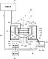
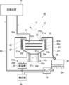
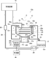
- FIG. 1 is a schematic diagram showing a processing system having an example of a processing apparatus according to an embodiment of the invention
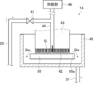
- FIG. 2 is a schematic diagram showing an example of a developing apparatus.
- a processing system 10 illustrated in FIG. 1 includes a processing device 12 and a developing device 14, and the processing device 12 is connected to the developing device 14.
- a development fatigue solution containing solid matter generated by removing an unexposed portion of the photosensitive resin plate after imagewise exposure is generated by development using the washing solution.
- a developing fatigue solution is supplied from the developing device 14 to the processing device 12 via the pipe 31.
- the processing apparatus 12 includes a first solid material 36 having a specific gravity smaller than that of the washout liquid contained in the development fatigue liquid Qw and a second solid matter having a higher specific gravity than the washout liquid in the rotating container 20 with respect to the development fatigue liquid Qw. 37. The separated first solid material 36 and second solid material 37 are removed from the container 20.
- the processing device 12 performs, for example, centrifugal sedimentation type centrifugation, and includes a container 20, an inside disk 22, a keeper disk 23, a case 24, a drive unit 26, a pump 29, and a removal unit 33. And a control unit 38.
- the drive unit 26 and the pump 29 are connected to the control unit 38, and the operation of the drive unit 26 and the pump 29 is controlled by the control unit 38.
- the operation of the removing unit 33 is also controlled by the control unit 38.
- the container 20 stores the development fatigue fluid Qw, and is formed by integrating a cylindrical body 20a, a truncated cone-shaped inclined portion 20b, and a cylindrical bottom 20c.
- a lid 21a is provided in the opening 20e of the body 20a.
- the lid 21a is made of a member having a circular band shape in plan view and has an opening 21b.
- the one with the trunk 20a is on the upper side
- the one with the bottom 20c is on the lower side
- the opening 21b is arranged on the upper side.
- a shutter 21c is provided in the opening 20f of the inclined portion 20b.
- the shutter 21c can be opened and closed, and the inclined portion 20b and the bottom portion 20c are not communicated with each other when the shutter 21c is closed.
- the drive unit 26 is provided with a drive shaft 35a, and the drive shaft 35a is provided with a drive gear 35b.
- a driven gear 35c is provided around the bottom 20c, and the drive gear 35b and the driven gear 35c are engaged with each other.
- the drive unit 26 rotates the container 20 around the central axis C in the direction R, for example, in the direction R, and the first solid material 36 having a specific gravity smaller than the washing liquid contained in the development fatigue liquid Qw and the specific gravity from the washing liquid.
- the second solid matter 37 having a large size is centrifuged in the container 20.
- the container 20 also functions as a rotating body.
- the drive part 26 is comprised with a motor, for example. If the container 20 can be rotated using the drive unit 26, the combination of the drive shaft 35a, the drive gear 35b, and the driven gear 35c is not limited, and a combination of the drive shaft, a pulley, and a transmission belt is used. You can also
- the required acceleration is 300 G or more when the particle size is 1 ⁇ m or more, depending on the size of the dispersed solid matter, when the acceleration is expressed by the centrifugal effect G, which is a multiple of the gravitational acceleration. In order to achieve a sufficient removal treatment effect, it is preferably 500 G or more. On the other hand, when the particle size is less than 1 ⁇ m, it is preferably 1000 G or more. For this reason, what can produce the above-mentioned centrifugal effect G is used for the drive part 26.
- FIG. The number of rotations (rpm (revolution per minute)) and rotation time of the container 20 by the drive unit 26 and the timing of rotation of the container 20 are controlled by the control unit 38.
- the control unit 38 rotates and centrifuges the container 20 in which the developing fatigue liquid Qw is stored by the driving unit 26, and accumulates the first solid matter 36 on the keeper disk 23, and drives the control unit 38. After the rotation of the container 20 by the unit 26 is stopped and the first solid matter 36 accumulated on the keeper disk 23 is held by the keeper disk 23, the development fatigue fluid Qw is discharged from the container 20, The container 20 is rotated again by the driving unit 26.
- the bottom 20c can be opened and closed at the bottom 20d. As shown in FIG. 5, by opening the shutter 21c and the bottom surface 20d, the solid matter in the container 20 can be discharged to the outside. In this case, for example, a tray 32 (see FIG. 5) is disposed below the bottom surface 20d, and the solid matter in the container 20 is collected.
- a regulating member is provided in the container 20 and facing the opening 21b.
- the regulating member holds the first solid material 36 in the container 20.
- the restricting member is, for example, the inside disk 22.
- At least one holding member is provided in the container 20 and on the side opposite to the opening 21b with respect to the regulating member.
- the holding member holds the first solid material 36 collected by centrifugation.
- the holding member is, for example, a keeper disk 23, and the processing device 12 in FIG. 1 has three keeper disks 23.
- the inside disk 22 and the three keeper disks 23 are spaced apart from each other.
- the inside disk 22 is disposed on the lid 21a side so as to face the opening 21b, and the three keeper disks 23 are disposed on the opposite side of the opening 21b with respect to the inside disk 22.
- the number of keeper disks 23 is not limited to a plurality, and at least one keeper disk 23 is sufficient.
- the inside disk 22 and the keeper disk 23 are both fixed in the container 20 and are configured to rotate together with the container 20 when the container 20 rotates, but are not limited thereto. If the centrifugal force can be applied to the first solid material 36 held by the keeper disk 23 when the container 20 rotates, the installation state of the inside disk 22 and the keeper disk 23 with respect to the container 20 is particularly limited. It is not something.
- the case 24 covers the container 20 and stores the development fatigue fluid Qw overflowing from the opening 21 b of the container 20. Further, the container 20 and the case 24 can communicate with each other through an openable / closable outlet (not shown) provided in the inclined portion 20 b of the container 20. For this reason, the developing fatigue fluid Qw in the container 20 can be discharged to the case 24.
- the case 24 is provided with a discharge path 25 serving as a flow path for the developing fatigue liquid Qw from the case 24 to the defoaming tank 27.
- the development fatigue fluid Qw in the case 24 passes through the discharge path 25 and is stored in the defoaming tank 27.
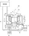
- FIG. 9 is a schematic diagram showing a processing system 10 a having an example of a processing apparatus according to another embodiment of the present invention
- a separation membrane 30 is further provided at a position closer to the developing device 14 than the pump 29.
- the separation membrane 30 separates solid matter generated by development.
- the separation membrane 30 is not particularly limited as long as it can separate the solid matter contained in the development fatigue solution Qw, and is appropriately determined depending on the size of the solid matter to be separated. Note that the separation membrane 30 is not always necessary, and may be configured not to be provided like the processing system 10 shown in FIG.
- the development fatigue fluid Qw stored in the defoaming tank 27 is reused as it is without passing through the separation membrane 30. Even when the separation membrane 30 is provided, it is not always necessary to pass the separation membrane 30. As described above, the developing fatigue fluid Qw may be repeatedly used without passing through the separation membrane 30. However, when the development fatigue liquid Qw is passed through the separation membrane 30, the concentration of the solid substance of the development fatigue liquid Qw returned to the developing device 14 can be further reduced, and the development fatigue liquid Qw is repeatedly used. This is preferable.
- symbol is attached
- the separation membrane 30 is capable of separating a solid having a particle size of 1 ⁇ m or less, for example.
- a filter having a separation ability of 0.1 ⁇ m is used as the separation membrane 30.
- a pipe 31 for supplying the developing fatigue liquid Qw into the container 20 is disposed in the container 20.
- the pipe 31 is connected to the developing device 14.
- the opening 31 a of the pipe 31 is disposed between the inside disk 22 and the uppermost keeper disk 23.
- the position of the opening 31a of the pipe 31 is not particularly limited as long as it is below the inside disk 22.
- the configuration of the container 20 is not particularly limited as long as the developing fatigue liquid Qw can be stored in the container 20 and is not plastically deformed by a centrifugal force acting during rotation for centrifugal separation.
- a container used in a centrifugal sedimentation type centrifugal separator can be used as appropriate.
- the container 20 is configured without a hole, that is, the body portion 20a, the inclined portion 20b, and the bottom portion 20c are configured with members having no holes.
- a basket type rotor is used for the container 20.
- the capacity of the container 20 is not particularly limited, and is appropriately determined depending on the amount of solids contained in the developing fatigue liquid Qw, the plate making amount in the developing device 14, and the like.
- the inside disk 22 is for holding the first solid material 36 having a specific gravity smaller than that of the washing liquid in the container 20 as in the case of the above-described regulating member, and is constituted by a disk having an opening 22a, for example.
- the inside disk 22 is provided in the vicinity of the opening 21b in the container 20 so that the first solid matter 36 collected inside the container 20 is not discharged together with the developing fatigue liquid Qw to the outside of the container 20 by centrifugation. It is done.
- the first solid material 36 gathered inside the container 20 is blocked by the inside disk 22 and captured in the container 20.
- the developing fatigue fluid Qw passes through the outer edge side of the inside disk 22 and overflows from the opening 21 b of the container 20 into the case 24.
- the inside disk 22 is made of metal or resin. It is preferable that the inside disk 22 can be installed without removing the lid 21a. In this case, the inside disk 22 is made of a flexible material such as a resin.
- the keeper disk 23 holds the first solid material 36 that is accumulated when it is centrifuged, as in the above-described holding member.
- the first solid material 36 accumulated on the keeper disk 23 is held on the keeper disk 23.
- the holding member holds the first solid material 36
- the first solid material 36 on the keeper disk 23 is finally removed from the keeper disk 23. Therefore, the keeper disk 23 is preferably formed of a flat plate on which the first solid matter 36 is easily deposited and the first solid matter 36 is easily blown off when the container 20 is rotated. For this reason, for example, the keeper disk 23 is formed of a disc having no opening.
- the keeper disk 23 only needs to be capable of accumulating the first solid matter 36 and holding the first solid matter 36. Therefore, at least during centrifuging, the keeper disk 23 corresponds to the mass of the first solid matter 36. It suffices if there is a member at the position where the components are accumulated. Therefore, the keeper disk 23 may be a disk having an opening as will be described later.
- the keeper disk 23 is made of metal, for example.
- the keeper disk 23 may be made of the same material as the inside disk 22.
- the defoaming tank 27 stores the development fatigue fluid Qw.
- the development fatigue fluid Qw is once supplied to the defoaming tank 27 and after the bubbles are removed, it is returned to the developing device 14 by the pump 29.
- the configuration of the defoaming tank 27 is not particularly limited as long as it can store the development fatigue solution Qw.
- the pump 29 returns the developing fatigue fluid Qw from the defoaming tank 27 to the developing device 14.
- the configuration of the pump 29 is not particularly limited as long as it can be returned to the developing device 14.
- the length of the pipe 28, the height difference between the defoaming tank 27 and the developing device 14, and the development fatigue liquid Qw are not limited. This is appropriately determined according to the return amount. Note that the timing of returning the development fatigue fluid Qw stored in the defoaming tank 27 by the pump 29 is controlled by the control unit 38.
- the removal unit 33 includes, for example, a scraper 34 and a moving unit (not shown) that moves the scraper 34.
- the scraper 34 scrapes and removes the deposits deposited on the inner wall 20g of the container 20.
- the scraper 34 removes the first solid material 36 and the second solid material 37 deposited on the inner wall 20g.
- the scraper 34 is configured by, for example, a flat plate that can move along the inner wall 20g.
- the scraper 34 is fixed in the container 20 at the time of centrifugation, and rotates at the same direction R and the same speed as the container 20. When removing, the scraper 34 is rotated by the moving unit in a direction r (see FIG. 6) opposite to the direction R in which the container 20 rotates.
- the first solid matter 36 is held in the keeper disc 23 when the development fatigue solution Qw is collected, so the first solid matter 36 is mixed into the development fatigue solution Qw. It becomes difficult to reduce the concentration of the solid matter of the development fatigue liquid Qw discharged from the container 20. For this reason, when the development fatigue solution Qw is reused as the washout solution Q, the increase in the concentration of the solid matter is suppressed even if it is repeatedly used. As a result, the development fatigue solution Qw is used as a washout solution more times. Can be reused. Further, by providing the keeper disk 23, the developing fatigue liquid Qw is also held on the keeper disk 23 in addition to the first solid material 36. Thereby, the moisture content of the 1st solid substance 36 and the 2nd solid substance 37 which were discharged
- the developing device 14 develops the photosensitive resin plate using a water-based washing solution.
- the developing device 14 includes a developing tank 40 and a brush 42.
- the brush 42 is provided on the drive member 43.
- the brush 42 is provided with a supply pipe 44.
- the supply pipe 44 is connected to the supply unit 46.
- the washing liquid is supplied from the supply section 46 through the supply pipe 44 to the surface 50 a of the photosensitive resin plate 50 from the brush 42.
- the development fatigue solution Qw includes a washing solution Q.
- the developing tank 40 is connected to the pipe 31. It is sent out from the pipe 31 as a developing fatigue liquid Qw.
- the pipe 28 is connected to the supply pipe 44.
- a valve 47 is provided between the pipe 28 and the supply pipe 44. The communication between the pipe 28 and the supply pipe 44 is controlled by opening and closing the valve 47.
- the valve 47 is closed.
- the processed development fatigue solution Qw is supplied from the supply pipe 44 to the photosensitive resin plate 50 through the pipe 28. In this case, the valve 47 is opened.
- the separation membrane 30 is provided in the pipe 28 as described above, and the processed development fatigue liquid Qw is supplied through the separation membrane 30.
- the developing device 14 is not particularly limited in the developing method, and may be a batch type or a conveyance type. Further, the developing device 14 may be configured to spray the washing solution onto the photosensitive resin plate 50 to remove the unexposed portion, and the photosensitive resin plate 50 is immersed in the washing solution to remove the unexposed portion. Form may be sufficient.
- the configuration of the photosensitive resin plate 50 is not particularly limited.
- the photosensitive resin plate 50 forms a flexographic printing plate used for flexographic printing.
- the photosensitive resin plate 50 is preferably one that can be developed with an aqueous developer containing water as a main component, or one that is called a water-developable flexographic printing plate precursor.
- the photosensitive resin plate 50 may be a known flexographic printing plate precursor that can be developed with an aqueous developer, and may be a CTP (Computer To Plate) compatible flexographic printing plate with a black layer layer applied to the surface. .
- CTP Computer To Plate
- 3 to 5 show a processing method using a processing system having an example of a processing apparatus according to an embodiment of the present invention in the order of steps.
- the same components as those of the processing system 10 shown in FIG. 1 are denoted by the same reference numerals, and detailed description thereof is omitted.
- 3 and 4 the illustration of the scraper 34 is omitted.
- the surface 50a (see FIG. 2) of the photosensitive resin plate 50 is exposed in an imagewise exposure, that is, a specific pattern by an exposure apparatus (not shown).
- the photosensitive resin plate 50 after the imagewise exposure is conveyed to the developing device 14, and the developing device 14 uses a brush 42 (see FIG.
- the development fatigue fluid Qw is supplied into the container 20 of the processing apparatus 12 via the pipe 31. Centrifugation is performed by rotating the container 20 about the central axis C as a rotation axis by the drive unit 26. Centrifugation separates solids contained in the developing fatigue liquid Qw in the container 20 according to the mass.
- the first solid material 36 and the second solid material 37 are centrifuged in the container 20 under centrifugal conditions such as a predetermined rotation speed and rotation time, and the second solid material 37 is then removed from the container 20.
- the first solid matter 36 is accumulated on the keeper disk 23 provided in the container 20 (first step).
- the rotation of the container 20 by the drive unit 26 is stopped, and the centrifugation is stopped. Then, with the first solid material 36 accumulated on the keeper disk 23 held by the keeper disk 23, for example, an outlet (not shown) of the inclined portion 20b is opened to open the container 20 and the case. 24, the development fatigue fluid Qw is discharged from the container 20 to the case 24 (second step).
- the development fatigue fluid Qw discharged to the case 24 is stored in the defoaming tank 27.
- the second solid material 37 is deposited on the inner wall 20g of the body 20a of the container 20, and the first solid material 36 is It is in a state of being accumulated on the keeper disk 23.
- the container 20 is rotated by the drive unit 26, and the centrifugal separation is performed again.
- the first solid material 36 held on the keeper disk 23 is removed from the keeper disk 23 by the centrifugal force acting during the rotation (third step).
- the first solid material 36 is blown off and deposited on the inner wall 20 g of the body portion 20 a of the container 20, but the second solid material 37 also applies centrifugal force when the container 20 rotates. It is received and held on the inner wall 20 g of the body 20 a of the container 20.
- the 1st solid substance 36 and the 2nd solid substance 37 are deposited on the inner wall 20g of the trunk
- the first solid matter 36 and the second solid matter 37 are simultaneously removed from the container 20 by removing the deposit on the inner wall 20g.
- the 1st solid substance 36 and the 2nd solid substance 37 are removed in the state which discharged
- the developing fatigue liquid Qw stored in the defoaming tank 27 is returned to the developing device 14 via the pipe 28 by the pump 29.
- the separation film 30 is provided in the pipe 28, the solid matter contained in the development fatigue liquid Qw is removed, and the development apparatus 14 is subjected to development fatigue. Liquid Qw is returned.
- the development fatigue solution Qw is used as a washing solution Q (see FIG. 2) or a rinse solution for washing away the residue remaining on the plate surface of the photosensitive resin plate 50 after developing and removing the unexposed portion.
- the 1st solid substance 36 and the 2nd solid substance 37 which exist in the container 20 are removed by the removal part 33, it demonstrates using FIG.
- the shutter 21c is opened at the opening 20f of the inclined portion 20b, and the bottom surface 20d of the bottom 20c is opened.
- a tray 32 is disposed below 20d.
- the scraper 34 is rotated in a direction r opposite to the direction R in which the container 20 rotates.
- the first solid material 36 and the second solid material 37 deposited on the inner wall 20g of the container 20 are scraped, and the first solid material 36 and the second solid material 37 deposited on the inner wall 20g are separated.
- it is removed from the container 20.
- the first solid material 36 and the second solid material 37 are removed at the same time.
- the present invention is not limited to this and may be removed separately.
- the centrifugation is stopped and the developing fatigue liquid Qw is discharged out of the container 20, that is, between the second process and the third process, by the scraper 34, the container 20
- the second solid material 37 deposited on the inner wall 20 g is removed from the container 20.
- the container 20 is rotated again to remove the first solid material 36 from the keeper disk 23 (third step), and the first solid material 36 is deposited on the inner wall 20 g of the container 20.
- the first solid material 36 is removed from the container 20 by the scraper 34.
- the first solid material 36 and the second solid material 37 are separately removed as described above, the first solid material 36 is removed because the development fatigue liquid Qw is discharged from the container 20. And the 2nd solid substance 37 is removed in a state with a low moisture content. For this reason, when discarding the first solid material 36 and the second solid material 37 as solid waste, the amount of waste can be reduced.
- the first solid matter 36 and the second solid matter 37 removed from the container 20 are then provided with a dehydration step to further reduce the water content and to reduce the amount of waste when discarded as solid waste. Can be reduced.
- a vacuum type, a heating type, a pressure type, a centrifugal type, and the like can be used, but are not limited thereto.
- the processing apparatus 12 has a configuration in which one scraper 34 is provided as shown in FIG. 6, the present invention is not limited to this.
- a configuration having two scrapers 34 may be used as shown in FIG. 7.
- a configuration in which four scrapers 34 are provided may be employed.
- the scrapers 34 are arranged at equal intervals with respect to the central axis C, that is, at 90 ° intervals.
- the scraper 34 is not limited to a flat plate that moves along the inner wall 20g.
- the scraper 34 is disposed in the container 20 as a configuration of the removing unit 33, but the present invention is not limited to this, and the scraper 34 may be inserted into the container 20 when removing.
- the removal part 33 which inserts the scraper 34 in the container 20 may be provided separately from the processing apparatus 12.
- means (not shown) for jetting compressed air to the inner wall 20g of the container 20 may be provided, and the compressed air may be jetted at the same time as or before or after the solid substance removing operation of the scraper 34.
- the keeper disk 60 is, for example, a disc composed of an opening 60a and a main body 60b.
- the main body 60b of the keeper disk 60 only needs to be at a position where the above-described first solid material 36 is accumulated by centrifugation.
- FIG. 8 shows only the container 20.
- the keeper disk 60 is shown in FIG. 8, the keeper disk 60 may be the disk keeper disk 23 having no opening shown in FIG. 1 instead of the keeper disk 60.
- the development fatigue liquid Qw may be processed by a batch method in which the development fatigue liquid Qw is supplied from the developing device 14 to the processing device 12 after the photosensitive resin plate is developed. Further, a continuous system in which the developing fatigue liquid Qw is always supplied from the developing device 14 to the processing device 12 for processing may be used. A continuous system is preferred when the amount of development is large. Further, in the processing method of the development fatigue liquid Qw described above, a step of reusing the development fatigue liquid Qw discharged from the container 20 as a washing liquid, or a solid generated by developing the development fatigue liquid Qw discharged from the container 20 You may have the process of passing through the separation membrane 30 (refer FIG. 1) which removes a thing, and reusing as a washing
- FIG. 10 is a schematic diagram showing a processing system having a processing device for comparison.
- the same components as those of the processing system 10 shown in FIG. 1 are denoted by the same reference numerals, and detailed description thereof is omitted.
- the processing apparatus 102 shown in FIG. 10 differs from the processing system 10 shown in FIG. 1 in that the processing apparatus 12 is not provided with the keeper disk 23, and the other configuration is the same as the processing system 10 shown in FIG. The same.
- the processing apparatus 102 not provided with the keeper disk 23
- the first solid material 36 is accumulated at a position corresponding to the mass by centrifugal force.
- the rotation of the container 20 is stopped, the first solid material 36 is deposited on the inner surface 104 of the inclined portion 20b.
- the development fatigue liquid Qw in the container 20 is discharged into the case 24 as in the above-described processing method, the development fatigue liquid Qw discharged into the case 24 contains a large amount of the first solid matter 36, and development is performed. There is a concern that the solid content concentration of the fatigue fluid Qw may increase. Further, if the amount of accumulation on the inner surface 104 of the inclined portion 20b is large, it takes time to remove.
- the development fatigue solution to be processed by the processing method of the present invention is a washout solution containing a solid material generated by removing an unexposed portion by development using a washout solution, that is, a washout solution containing an uncured resin.
- a development fatigue liquid containing a conventionally known photosensitive resin composition for forming a general photosensitive resin layer can be used as a processing target.
- the processing method is preferably a processing fatigue liquid at the time of development by the LAM (Laser Ablation Masking) method, the uncured resin removed by the development is a photosensitive resin composition contained in the photosensitive resin composition.
- a photosensitive resin composition includes, for example, a composition containing a polymerization initiator, a polymerizable compound, a polymerization inhibitor, a plasticizer, and the like.
- the development fatigue solution which is the treatment target of this treatment method may contain a polymerization initiator, a polymerizable compound, a polymerization inhibitor, a plasticizer and the like in addition to the uncured resin.
- the uncured resin contained in the development fatigue liquid is a solid material generated by removing an unexposed portion.
- Examples of the uncured resin contained in the development fatigue liquid include water-dispersible latex, rubber component, polymer component, and uncrosslinked ethylenically unsaturated compound (polymer).
- water dispersible latex examples include polybutadiene latex, natural rubber latex, styrene-butadiene copolymer latex, acrylonitrile-butadiene copolymer latex, polychloroprene latex, polyisoprene latex, polyurethane latex, methyl methacrylate-butadiene copolymer latex, Water-dispersed latex polymers such as vinylpyridine copolymer latex, butyl polymer latex, thiocol polymer latex, and acrylate polymer latex, or other components such as acrylic acid or methacrylic acid. Examples thereof include a polymer obtained by copolymerization.
- the rubber component examples include butadiene rubber, isoprene rubber, styrene-butadiene rubber, acrylonitrile rubber, acrylonitrile butadiene rubber, chloroprene rubber, polyurethane rubber, silicon rubber, butyl rubber, ethylene-propylene rubber, and epichlorohydrin rubber.
- the polymer component may be hydrophilic or hydrophobic, and specifically includes polyamide resin, unsaturated polyester resin, acrylic resin, polyurethane resin, polyester resin, polyvinyl alcohol resin, and the like.
- the solid material having a specific gravity smaller than that of the washing liquid is, for example, a photosensitive resin such as a rubber component and latex.
- the solid matter having a specific gravity greater than that of the washing solution is a component of the overcoat layer such as carbon.
- Examples of the ethylenically unsaturated compound (polymer) include a (meth) acryl-modified polymer having an ethylenically unsaturated bond in the molecule.
- Examples of the (meth) acryl-modified polymer include (meth) acryl-modified butadiene rubber and (meth) acryl-modified nitrile rubber.
- “(Meth) acryl” is a notation representing acryl or methacryl
- “(meth) acrylate” described later is a notation representing acrylate or methacrylate.
- the uncured resin contained in the development fatigue solution is not particularly limited, but is preferably 70% by mass or less, and more preferably 35% by mass or less.
- the polymerization initiator that may be contained in the development fatigue liquid is preferably a photopolymerization initiator.
- the photopolymerization initiator include alkylphenones, acetophenones, benzoin ethers, benzophenones, thioxanthones, anthraquinones, benzyls, and biacetyls. Among them, alkylphenones are preferable. .
- photopolymerization initiators for alkylphenones include 2,2-dimethoxy-1,2-diphenylethane-1-one, 1-hydroxy-cyclohexyl-phenyl-ketone, and 2-hydroxy- 2-methyl-1-phenyl-propan-1-one and the like.
- the concentration of the polymerization initiator that may be contained in the development fatigue solution is not particularly limited, but is preferably 2.0% by mass or less, and more preferably 1.0% by mass or less.
- polymerizable compound examples include ethylenically unsaturated compounds corresponding to so-called monomer components other than the above-described ethylenically unsaturated compounds (polymers).
- the ethylenically unsaturated compound may be a compound having one ethylenically unsaturated bond or a compound having two or more ethylenically unsaturated bonds.
- Specific examples of the compound having one ethylenically unsaturated bond include 2-hydroxyethyl (meth) acrylate, 2-hydroxypropyl (meth) acrylate, 2-hydroxybutyl (meth) acrylate, and 3-chloro-2.
- -(Meth) acrylate having a hydroxyl group such as hydroxypropyl (meth) acrylate, ⁇ -hydroxy- ⁇ '-(meth) acryloyloxyethyl phthalate; methyl (meth) acrylate, ethyl (meth) acrylate, propyl (meth) acrylate, Alkyl (meth) acrylates such as butyl (meth) acrylate, isoamyl (meth) acrylate, 2-ethylhexyl (meth) acrylate, lauryl (meth) acrylate, stearyl (meth) acrylate; cyclohexyl (meth) acrylate, etc.
- hydroxyl group such as hydroxypropyl (meth) acrylate, ⁇ -hydroxy- ⁇ '-(meth) acryloyloxyethyl phthalate; methyl (meth) acrylate, ethyl (meth) acryl
- Cycloalkyl (meth) acrylate halogenated alkyl (meth) acrylates such as chloroethyl (meth) acrylate and chloropropyl (meth) acrylate; Methoxyethyl (meth) acrylate, ethoxyethyl (meth) acrylate, butoxyethyl (meth) acrylate, etc.
- Alkoxyalkyl (meth) acrylates phenoxyalkyl (meth) acrylates such as phenoxyethyl acrylate and nonylphenoxyethyl (meth) acrylate; ethoxydiethylene glycol (meth) acrylate, methoxytriethylene glycol (meth) acrylate, methoxydipropylene glycol ( Alkoxyalkylene glycol (meth) acrylates such as meth) acrylate; 2,2-dimethylaminoethyl (meth) acrylate DOO, 2,2-diethylaminoethyl (meth) acrylate, 2-hydroxyethyl (meth) acrylate, and 3-chloro-2-hydroxypropyl (meth) acrylate.
- the ethylenically unsaturated compound having two or more ethylenically unsaturated bonds include alkyldiol di (meth) acrylates such as 1,9-nonanediol di (meth) acrylate; diethylene glycol di (meth) acrylate Polyethylene glycol di (meth) acrylate such as polypropylene glycol di (meth) acrylate such as dipropylene glycol di (meth) acrylate; trimethylolpropane tri (meth) acrylate, pentaerythritol tri (meth) acrylate, pentaerythritol tetra (meth) ) Acrylates, glycerol tri (meth) acrylates, ethylene glycol diglycidyl ethers with compounds with ethylenically unsaturated bonds and active hydrogen such as unsaturated carboxylic acids or unsaturated alcohols Polyvalent (meth) acrylate obtained by reaction; polyvalent (me
- the concentration of the polymerizable compound that may be contained in the development fatigue solution is not particularly limited, but is preferably 30.0% by mass or less, and more preferably 15.0% by mass or less.
- polymerization inhibitor examples include hydroquinone monomethyl ether, p-methoxyphenol, di-t-butyl-p-cresol, pyrogallol, t-butylcatechol, benzoquinone, 4,4'-thiobis (3-methyl-6-t-butylphenol), 2,2'-methylenebis (4-methyl-6-t-butylphenol), N-nitrosophenylhydroxyamine primary cerium salt, etc.
- the concentration of the polymerization inhibitor that may be contained in the development fatigue solution is not particularly limited, but is preferably 0.3% by mass or less, and more preferably 0.15% by mass or less.
- plasticizer examples include liquid rubber, oil, polyester, and phosphoric acid compounds.
- liquid rubber examples include liquid polybutadiene, liquid polyisoprene, and those modified with maleic acid or an epoxy group.
- oil examples include paraffin, naphthene and aroma.
- polyester examples include adipic acid-based polyester.
- phosphoric acid compounds include phosphate esters.
- the concentration of the plasticizer that may be contained in the development fatigue solution is not particularly limited, but is preferably 30% by mass or less, and more preferably 15% by mass or less.
- the wash-out solution contained in the development fatigue solution is preferably an aqueous wash-out solution, and may be a solution composed only of water, or contains 50% by mass or more of water, and a water-soluble compound is added.
- An aqueous solution may be used.
- water-soluble compounds include surfactants, acids, and alkalis.
- the surfactant examples include an anionic surfactant, a nonionic surfactant, a cationic surfactant, and an amphoteric surfactant.
- an anionic surfactant is preferable.
- Specific examples of the anionic surfactant include aliphatic carboxylates such as sodium laurate and sodium oleate; higher alcohol sulfates such as sodium lauryl sulfate, sodium cetyl sulfate and sodium oleyl sulfate; Polyoxyethylene alkyl ether sulfate salts such as sodium polyoxyethylene lauryl ether sulfate; polyoxyethylene alkyl allyl ether sulfate salts such as sodium polyoxyethylene octylphenyl ether sulfate, sodium polyoxyethylene nonylphenyl ether sulfate; Alkyl sulfonates such as alkyl diphenyl ether disulfonate, sodium dodecyl sulfon
- nonionic surfactants include polyoxyethylene alkyl ethers such as polyoxyethylene oleyl ether or polyoxyethylene lauryl ether, and polyoxyethylene nonyl phenyl ether or polyoxyethylene octylphenyl ether.
- Ethylene alkyl phenyl ethers polyoxyethylene polyoxypropylene glycols, polyethylene glycol monostearate or polyethylene glycol monooleate, mono- and diesters of polyethylene glycol with fatty acids such as polyethylene glycol dilaurate, sorbitan monolaurate or sorbitan monooleate
- Fatty acid and sorbitan esters such as polyoxyethylene sorbitan monolaurate or Esters of sorbitan polyoxyethylene adducts such as oxyethylene sorbitan monocytearate or polyoxyethylene sorbitan trilaurate with fatty acids, esters of fatty acids such as sorbitol monopartimidate or sorbit dilaurate, sorbites, polyoxy Esters of sorbite polyoxyethylene adducts such as ethylene sorbite monostearate or polyoxyethylene sorbitdiolate with fatty acids, esters of fatty acids such as pentaerythritol monoste
- fatty acid alkanolamides such as lauric acid diethanolamide or lauric acid monoethanolamide
- lauryldimethylamine examples include amine compounds such as side, fatty acid alkanolamines such as stearyl diethanolamine, polyoxyethylene alkylamines, triethanolamine fatty acid esters, phosphates, carbonates, silicates, and other alkaline salt compounds. . These may be used alone or in combination of two or more.
- cationic surfactant examples include primary and secondary amine salts such as monostearyl ammonium chloride, distearyl ammonium chloride, and tristearyl ammonium chloride, stearyl trimethyl ammonium chloride, and distearyl dimethyl ammonium.
- Quaternary ammonium salts such as chloride, stearyldimethylbenzylammonium chloride, alkylpyridinium salts such as N-cetylpyridinium chloride or N-stearylpyridinium chloride, N, N dialkylmorpholinium salts, polyethylene polyamine fatty acid amide salts, aminoethylethanol Acetates of urea compounds of amides of stearic acid with amines, 2-alkyl-1-hydroxyethylimidazolinium chloride Ido, and the like. These may be used alone or in combination of two or more.
- amphoteric surfactants include amino acid types such as sodium laurylamine propionate, carboxybetaine types such as lauryl dimethyl betaine or lauryl dihydroxyethyl betaine, and sulfones such as stearyl dimethyl sulfoethylene ammonium ethylene ammonium betaine.
- amino acid types such as sodium laurylamine propionate
- carboxybetaine types such as lauryl dimethyl betaine or lauryl dihydroxyethyl betaine
- sulfones such as stearyl dimethyl sulfoethylene ammonium ethylene ammonium betaine.
- betaine type imidazolinium betaine type, and restin. These may be used alone or in combination of two or more.
- the acid include inorganic acids or organic acids such as hydrochloric acid, sulfuric acid, nitric acid, phosphoric acid, formic acid, acetic acid, oxalic acid, succinic acid, citric acid, malic acid, maleic acid, and paratoluenesulfonic acid.
- the alkali include lithium hydroxide, sodium hydroxide, magnesium hydroxide, potassium hydroxide, calcium hydroxide, calcium oxide, sodium carbonate, sodium bicarbonate, calcium carbonate and the like.
- the present invention is basically configured as described above.
- the processing method and processing apparatus of the present invention have been described in detail above, but the present invention is not limited to the above-described embodiments, and various improvements or modifications may be made without departing from the spirit of the present invention. Of course.
- the present invention should not be construed as being limited by the specific examples shown below.
- the solid content concentration of the development fatigue solution represents the solid content concentration of the development fatigue solution discharged from the container 20 after the centrifugal treatment in Examples 1 to 3 and Comparative Examples 3 to 4. 2 represents the solid content concentration of the developing fatigue solution.
- the solid content concentration of the developing fatigue liquid and the moisture content of the discharged solid matter were measured.
- the solid content concentration of the developing fatigue solution and the moisture content of the discharged solid are shown in Table 1 below.
- ⁇ Measurement method of solid content concentration of development fatigue fluid 10 g of the development fatigue solution to be measured was placed in an aluminum container and dried in an oven PHH-201 (manufactured by ESPEC) at 95 ° C. for 12 hours. After drying, the mass of the residue was measured to determine the solid content concentration of the developing fatigue solution. The results are shown in the column of solid content concentration (mass%) of the developing fatigue solution in Table 1 below.
- Example 1 In Example 1, the above-described developing fatigue solution was processed using a processing apparatus having the configuration shown in FIG. In Example 1, centrifugation was carried out, and once the centrifugation was stopped, the container was rotated again. Further, a scraper and a compressed air jet were used to remove the solid matter in the container. In “2500 rpm ⁇ 5 L / min” shown in the column of centrifugation in Table 1 below, “2500 rpm” indicates the number of rotations during centrifugation. “5 L / min (liter / min)” indicates a flow rate at which the developing fatigue solution is sent to the centrifuge.
- the processing amount of the second embodiment is different from that of the first embodiment, and is otherwise the same as the first embodiment.
- the processing amount indicates how many square meters (m 2 ) and development processing of the photosensitive resin plate is, and represents the total area (m 2 ) of the developed photosensitive resin plate.
- the third embodiment is the same as the first embodiment except that a processing apparatus having a separation membrane having the configuration shown in FIG. 9 is used as compared to the first embodiment.
- a filter Cobetter membrane filter APSHA0010 having a resolution of 0.1 ⁇ m was used.
- Comparative Example 1 In Comparative Example 1, the solid content concentration of the development fatigue solution was measured for a development fatigue solution with a throughput of 20 m 2 . In Comparative Example 1, the development fatigue solution does not pass through the filter. In Comparative Example 1, since the moisture content (% by mass) of the discharged solid was not measured, “-” was written in the column of the moisture content (% by mass) of the discharged solid. (Comparative Example 2) In Comparative Example 2, the solid content concentration of the development fatigue solution was measured for a development fatigue solution with a throughput of 25 m 2 . In Comparative Example 2, the development fatigue solution does not pass through the filter. In Comparative Example 2, since the moisture content (mass%) of the discharged solid was not measured, “-” was written in the column of the moisture content (mass%) of the discharged solid.
- Comparative Example 3 differs from Example 1 in that a processing apparatus without a keeper disk having the configuration shown in FIG. 10 was used and that the container was not rotated again after centrifugation. Same as Example 1.
- Comparative Example 4 Comparative Example 4 is the same as Comparative Example 3 except for the amount of treatment compared to Comparative Example 3.
- Example 1 to 3 had less water content in the discharged solids than Comparative Examples 1 to 4.
- Example 1 and Comparative Example 3 having the same throughput Example 1 had a lower solid content concentration (mass%) of the developing fatigue solution.
- Example 2 and Comparative Example 4 having the same processing amount and no filter Example 2 had a lower solid content concentration (% by mass) of the developing fatigue solution. From the above, the effect of the holding member is clear.
Abstract
Description
特許文献1では、捕捉された固形分散物は回分式の場合は遠心分離のための回転を止めた後に、取り出す必要がある。取り出す方法としては、(i)手でヘラ等を用いて取り出す方法、(ii)遠心分離機にスクレーパーを設置し、低速で回転させながらローター内部にスクレーパーを挿入し掻き取る方法、および(iii)ローター内部に袋状の物または成型品を内装し、内装物ごと取り出す方法が挙げられる。
特許文献1では、上述の(i)~(iii)のいずれの方法でも、洗い出し液だけを抜き取ることができない。このため、洗い出し液より比重の大きい固形物と、洗い出し液より比重の小さい固形物との両方を除去する際、洗い出し液が多く混入して含水率が高くなり、固体廃棄物として廃棄する際、廃棄量が多くなる。また、特許文献1では処理済みの洗い出し液を再使用することが記載されているが、上述のように含水率が高くなると、再使用できる洗い出し液の量が少なくなる。 In recent years, a flexographic printing plate material compatible with CTP (Computer To Plate), which has a black layer layer coated on the surface, has appeared, and there is an increasing demand for simultaneously separating solid matter having a specific gravity greater than the washing solution. In patent document 1, it is possible to isolate | separate both the solid substance with larger specific gravity than a washout liquid, and the solid substance with a specific gravity smaller than a washout liquid.
In Patent Document 1, in the case of a batch type, the captured solid dispersion needs to be taken out after stopping rotation for centrifugation. As a method of taking out, (i) a method of taking out by hand using a spatula, etc., (ii) a method of installing a scraper in a centrifuge, inserting the scraper into the rotor while rotating at low speed, and scraping (iii) There is a method in which a bag-like product or a molded product is installed inside the rotor, and the entire interior product is taken out.
In Patent Document 1, it is impossible to draw out only the washing solution by any of the methods (i) to (iii) described above. For this reason, when removing both solids having a higher specific gravity than the washing liquid and solids having a lower specific gravity than the washing liquid, a large amount of the washing liquid is mixed to increase the water content, and when it is discarded as solid waste, The amount of waste increases. Further, in Patent Document 1, it is described that the treated washing liquid is reused. However, as the moisture content increases as described above, the amount of washing liquid that can be reused decreases.
第3の工程の後に、第1の固形物と第2の固形物とを同時に容器から除去する工程を有することが好ましい。
容器から排出された現像疲労液を洗い出し液として再使用する工程、または容器から排出された現像疲労液を、現像により発生する固形物を除去する分離膜を通過させて洗い出し液として再使用する工程を有することが好ましい。
また、容器から排出された現像疲労液は、未露光部を現像除去した後に版面に残存するカスを洗い流すリンス液として再使用してもよい。 Between the second step and the third step, there is a step of removing the second solid material from the container, and after the third step, there is a step of removing the first solid material from the container. Is preferred.
It is preferable to have the process of removing a 1st solid substance and a 2nd solid substance from a container simultaneously after a 3rd process.
A process of reusing the development fatigue liquid discharged from the container as a washing liquid, or a process of reusing the development fatigue liquid discharged from the container as a washing liquid through a separation membrane that removes solid matter generated by development. It is preferable to have.
Further, the development fatigue liquid discharged from the container may be reused as a rinse liquid for washing away the residue remaining on the plate surface after the unexposed portion is developed and removed.
規制部材は、開口を有する円板であり、保持部材は、円板、または開口を有する円板であることが好ましい。
現像により発生する固形物を除去する分離膜を有し、容器から排出された現像疲労液を分離膜を通過させて洗い出し液として再使用するか、または分離膜を通過させることなく洗い出し液として再使用することが好ましい。
容器から排出された現像疲労液を、洗い出し液として再使用することが好ましい。 It is preferable to have a removal unit that removes the first solid and the second solid present in the container from the container.
The restricting member is preferably a disk having an opening, and the holding member is preferably a disk or a disk having an opening.
It has a separation membrane that removes solid matter generated by development, and the development fatigue fluid discharged from the container is passed through the separation membrane and reused as a washing solution, or re-used as a washing solution without passing through the separation membrane. It is preferable to use it.
It is preferable to reuse the development fatigue solution discharged from the container as a washing solution.
なお、以下に説明する図は、本発明を説明するための例示的なものであり、以下に示す図に本発明が限定されるものではない。
なお、以下において数値範囲を示す「~」とは両側に記載された数値を含む。例えば、εが数値α1~数値β2とは、εの範囲は数値α1と数値β2を含む範囲であり、数学記号で示せばα1≦ε≦β2である。
「具体的な数値で表された角度」および「垂直」等の角度は、特に記載がなければ、該当する技術分野で一般的に許容される誤差範囲を含む。 Hereinafter, a processing method and a processing apparatus of the present invention will be described in detail based on preferred embodiments shown in the accompanying drawings.
In addition, the figure demonstrated below is an illustration for demonstrating this invention, and this invention is not limited to the figure shown below.
In the following, “to” indicating a numerical range includes numerical values written on both sides. For example, the epsilon numerical alpha 1 ~ numerical beta 2, the range of epsilon is a range including the numerical alpha 1 and numerical beta 2, is α 1 ≦ ε ≦ β 2 If Shimese in mathematical symbols.
Unless otherwise specified, angles such as “an angle expressed by a specific numerical value” and “vertical” include an error range generally allowed in the corresponding technical field.
図1に示す処理システム10は、処理装置12と現像装置14とを有し、処理装置12は現像装置14に接続されている。 FIG. 1 is a schematic diagram showing a processing system having an example of a processing apparatus according to an embodiment of the invention, and FIG. 2 is a schematic diagram showing an example of a developing apparatus.
A
処理装置12は、現像疲労液Qwについて、回転する容器20内で、現像疲労液Qwに含まれる洗い出し液より比重の小さい第1の固形物36と、洗い出し液より比重の大きい第2の固形物37とを遠心分離する。分離された第1の固形物36と、第2の固形物37とを容器20内から除去する。
処理装置12は、例えば、遠心沈降型の遠心分離を実施するものであり、容器20と、インサイドディスク22と、キーパーディスク23と、ケース24と、駆動部26と、ポンプ29と、除去部33と、制御部38とを有する。駆動部26とポンプ29とは制御部38に接続されており、制御部38により駆動部26とポンプ29の動作とが制御される。また、除去部33も制御部38により動作が制御される。 In the developing
The
The
駆動部26には駆動軸35aが設けられており、駆動軸35aに駆動ギア35bが設けられている。底部20cの周囲に従動ギア35cが設けられており、駆動ギア35bと従動ギア35cとがかみ合わされている。駆動部26により駆動軸35aを回転させると駆動ギア35bが回転して従動ギア35cが回転し、容器20が回転する。このように駆動部26で発生させた駆動軸35aの回転を容器20に伝達することができる。駆動部26は、中心軸Cを回転軸として容器20を、例えば、方向Rに回転させて、現像疲労液Qwに含まれる洗い出し液より比重の小さい第1の固形物36と、洗い出し液より比重の大きい第2の固形物37とを容器20内で遠心分離させる。容器20は回転体として機能するものでもある。駆動部26は、例えば、モータで構成される。駆動部26を用いて容器20を回転させることができれば、駆動軸35aと駆動ギア35bと従動ギア35cとの組合せ限定されるものではなく、駆動軸とプーリーと伝動ベルトとを組み合わせたものを用いることもできる。 A
The
制御部38は、後に説明するが処理方法において、駆動部26により現像疲労液Qwが貯留された容器20を回転させて遠心分離し、第1の固形物36をキーパーディスク23に集積させ、駆動部26による容器20の回転を停止して、キーパーディスク23に集積された第1の固形物36がキーパーディスク23に保持された状態で、現像疲労液Qwが容器20内から排出された後、再度、駆動部26により容器20を回転させる。 In centrifugation, the required acceleration is 300 G or more when the particle size is 1 μm or more, depending on the size of the dispersed solid matter, when the acceleration is expressed by the centrifugal effect G, which is a multiple of the gravitational acceleration. In order to achieve a sufficient removal treatment effect, it is preferably 500 G or more. On the other hand, when the particle size is less than 1 μm, it is preferably 1000 G or more. For this reason, what can produce the above-mentioned centrifugal effect G is used for the
In the processing method, which will be described later, the
容器20内、かつ規制部材に対して開口部21bとは反対側に、少なくとも1つ保持部材が設けられている。保持部材は遠心分離により集積される第1の固形物36を保持するものである。保持部材は、例えば、キーパーディスク23であり、図1の処理装置12は、3つのキーパーディスク23を有する。 A regulating member is provided in the
At least one holding member is provided in the
インサイドディスク22が蓋21a側に開口部21bに面して配置され、3つのキーパーディスク23は、インサイドディスク22に対して開口部21bとは反対側に配置されている。なお、キーパーディスク23は、複数設けることに限定されるものではなく、少なくとも1つあればよい。
インサイドディスク22とキーパーディスク23とは、いずれも容器20内に固定されていて、容器20の回転した場合、容器20と一緒に回転する構成であるが、これに限定されるものではない。容器20が回転した際に、キーパーディスク23に保持された第1の固形物36に遠心力を作用させることができれば、インサイドディスク22およびキーパーディスク23の、容器20に対する設置状態は、特に限定されるものではない。 The
The
The
ケース24には、ケース24から消泡タンク27への現像疲労液Qwの流路となる排出路25が設けられている。ケース24内の現像疲労液Qwは排出路25を通り、消泡タンク27に貯留される。 The
The
しかしながら、現像疲労液Qwは分離膜30を通過させた方が、現像装置14に返送される現像疲労液Qwの固形物の濃度を、さらに低くすることができ、現像疲労液Qwを繰り返し使用することができるため好ましい。
なお、図9に示す処理システム10aにおいて、図1に示す処理システム10と同一構成物には同一符号を付して、その詳細な説明は省略する。 The
However, when the development fatigue liquid Qw is passed through the
In addition, in the
分析したところ、洗い出し液よりも比重の小さい固形物には、粒径が1~5μmの成分と粒径が1μm以下の成分があり、粒径が1~5μmの固形物はほとんど分離除去されているが、粒径が1μm以下の成分が徐々に増えていることが判明した。これは、遠心分離装置で除去できる成分は固形物が粒径1~5μmの固形物で、粒径が1μm以下の成分は遠心分離では除去できないため、再使用により濃度が上昇しているためと考えられる。このことから、分離膜30は、例えば、粒径が1μm以下の固形物を分離できるものであることが好ましい。例えば、分離膜30として、分離能が0.1μmのフィルターが用いられる。 Here, as described in Patent Document 1, it was verified that the processed liquid obtained by separating and removing solid matter having a specific gravity smaller than that of the washing liquid was reused as the washing liquid. There was a tendency for adhesion of residue to the resin plate.
As a result of analysis, solids having a specific gravity smaller than that of the washing liquid include components having a particle size of 1 to 5 μm and components having a particle size of 1 μm or less, and solids having a particle size of 1 to 5 μm are almost separated and removed. However, it was found that components having a particle size of 1 μm or less gradually increased. This is because the components that can be removed by the centrifuge are solids with a particle size of 1 to 5 μm, and components with a particle size of 1 μm or less cannot be removed by centrifugation, so the concentration increases due to reuse. Conceivable. From this, it is preferable that the
容器20は、内部に現像疲労液Qwを貯留でき、かつ遠心分離のための回転時に作用する遠心力により、塑性変形することがなければ、その構成は特に限定されるものではない。容器20は、例えば、遠心沈降型の遠心分離装置に利用されるものが適宜利用可能である。この場合、容器20は孔がない構成、すなわち、胴部20aと傾斜部20bと底部20cは孔がない部材で構成される。例えば、容器20には、バスケット型ローターが用いられる。
また、容器20の容量は、特に限定されるものではなく、現像疲労液Qwに含まれる固形物の量、および現像装置14での製版量等により適宜決定されるものである。 A
The configuration of the
Further, the capacity of the
容器20の内側に集まった第1の固形物36はインサイドディスク22により遮られて容器20内に捕捉される。現像疲労液Qwはインサイドディスク22の外縁側を通過して容器20の開口部21bからケース24に溢れ出る。 The
The first
保持部材は第1の固形物36を保持するが、最終的にはキーパーディスク23上の第1の固形物36は、キーパーディスク23上から取り除かれる。このことから、キーパーディスク23は、第1の固形物36が堆積されやすく、かつ容器20の回転時に第1の固形物36が飛ばされやすい平板で構成することが好ましい。このため、例えば、キーパーディスク23は開口のない円板で構成される。 The
Although the holding member holds the first
キーパーディスク23は、例えば、金属で構成される。キーパーディスク23は、インサイドディスク22と同じ材質とすることもできる。 However, the
The
ポンプ29は、上述のように、消泡タンク27の現像疲労液Qwを現像装置14に返送するものである。ポンプ29は、現像装置14に返送することができれば、その構成は特に限定されるものではなく、配管28の長さ、消泡タンク27と現像装置14との高さの差および現像疲労液Qwの返送量に応じて適宜決定されるものである。
なお、消泡タンク27に貯留された現像疲労液Qwのポンプ29による返送のタイミングは制御部38により制御される。 The
As described above, the
Note that the timing of returning the development fatigue fluid Qw stored in the
スクレーパー34は、例えば、内壁20gに沿って移動可能な平板で構成される。スクレーパー34は、遠心分離時には、容器20内に固定された状態にあり、容器20と同じ方向R、かつ同じ速度で回転する。除去する際には、移動部により、スクレーパー34は、容器20が回転する方向Rと反対の方向r(図6参照)に回転される。 The
The
また、キーパーディスク23を設けることにより、キーパーディスク23に第1の固形物36以外に現像疲労液Qwも保持される。これにより、容器20の外部に排出された、第1の固形物36および第2の固形物37の含水率を低くできる。 In the
Further, by providing the
現像装置14は、例えば、図2に示すように、現像槽40と、ブラシ42とが設けられている。ブラシ42は駆動部材43に設けられている。また、ブラシ42には、供給管44が設けられている。供給管44は供給部46に接続されている。現像装置14では、供給部46から供給管44を経て、ブラシ42から洗い出し液が感光性樹脂版50の表面50aに供給される。 Next, the developing
For example, as illustrated in FIG. 2, the developing
配管28は供給管44に接続されている。配管28と供給管44との間にはバルブ47が設けられている。バルブ47の開閉により、配管28と供給管44との連通が制御される。供給管44に処理済みの現像疲労液Qwを供給しない場合には、バルブ47は閉じられている。
配管28を経て処理済みの現像疲労液Qwが供給管44から感光性樹脂版50に供給される。この場合、バルブ47は開けられている。図9に示す別の実施形態の処理装置12では、配管28には、上述のように分離膜30が設けられており、処理済みの現像疲労液Qwは、分離膜30を通過されて供給される。 The developing
The
The processed development fatigue solution Qw is supplied from the
感光性樹脂版50は、その構成は特に限定されるものではなく、例えば、フレキソ印刷に使用されるフレキソ印刷版を形成するものである。感光性樹脂版50は、水を主成分とする水系現像液で現像可能なもの、水現像型のフレキソ印刷版原版と呼ばれるものであることが好ましい。感光性樹脂版50には、水系現像液で現像可能な公知のフレキソ印刷版原版が利用可能であり、表面にブラックレイヤー層が塗布された、CTP(Computer To Plate)対応のフレキソ版材でもよい。 The developing
The configuration of the
図3~図5に示す模式図は、本発明の実施形態の処理装置の一例を有する処理システムを用いた処理方法を工程順に示すものである。なお、図3~図5に示すの処理装置において、図1に示す処理システム10と同一構成物には同一符号を付して、その詳細な説明は省略する。また、図3および図4ではスクレーパー34の図示を省略している。
処理方法では、まず、露光装置(図示せず)により感光性樹脂版50(図2参照)の表面50a(図2参照)を、画像様露光、すなわち、特定のパターンで露光する。
画像様露光後の感光性樹脂版50を、現像装置14に搬送し、現像装置14において、現像槽40(図2参照)内にて、洗い出し液Q中でブラシ42(図2参照)を用いて感光性樹脂版50(図2参照)を現像する。洗い出し液Qを用いた現像によって、画像様露光後の感光性樹脂版50の未露光部が除去されることにより発生した固形物が洗い出し液Q(図2参照)中に分散する。これにより、固形物を含んだ現像疲労液Qwが発生する。 Next, a processing method will be described.
3 to 5 show a processing method using a processing system having an example of a processing apparatus according to an embodiment of the present invention in the order of steps. 3 to 5, the same components as those of the
In the processing method, first, the
The
駆動部26により、中心軸Cを回転軸として容器20を回転させて遠心分離を実施する。遠心分離により、容器20内で現像疲労液Qwに含まれる固形物が質量に応じて分離する。容器20内で第1の固形物36と第2の固形物37とを、予め定めれらた回転数および回転時間等の遠心分離条件にて遠心分離し、第2の固形物37を容器20の内壁20gに集積し、第1の固形物36を容器20内に設けられたキーパーディスク23に集積させる(第1の工程)。なお、上述の遠心分離の際に、容器20内の現像疲労液Qwは、大半が開口部21bから溢れ出てケース24に貯留される。ケース24に排出された現像疲労液Qwは排出路25を経て消泡タンク27に貯留される。 The development fatigue fluid Qw is supplied into the
Centrifugation is performed by rotating the
現像疲労液Qwが容器20のケース24に排出された後、図3に示すように、第2の固形物37は容器20の胴部20aの内壁20gに堆積し、第1の固形物36はキーパーディスク23上に集積された状態にある。 The rotation of the
After the development fatigue fluid Qw is discharged into the
なお、容器20内から現像疲労液Qwを排出した状態で第1の固形物36と第2の固形物37とが除去されるため、除去された第1の固形物36および第2の固形物37は含水率が低い。このため、第1の固形物36と第2の固形物37とを固体廃棄物として廃棄する際、廃棄量を少なくできる。 Next, in a state where the developing fatigue liquid Qw is discharged from the inside of the
In addition, since the 1st
除去部33を用いて容器20内の固形物を除去する場合、図5に示すように、傾斜部20bの開口部20fにシャッター21cを開け、かつ底部20cの底面20dを開けた状態で、底面20dの下方に受皿32を配置する。この状態で、図6に示すようにスクレーパー34を、容器20が回転する方向Rと反対の方向rに回転させる。これにより、容器20の内壁20gに堆積した第1の固形物36と第2の固形物37とが掻き取られ、内壁20gに堆積した第1の固形物36と第2の固形物37とが同時に容器20内から除去される。 Although the 1st
When removing the solid matter in the
上述のように第1の固形物36と第2の固形物37とを別々に除去する場合でも、容器20から現像疲労液Qwが排出された状態で除去されるため、第1の固形物36と第2の固形物37とは含水率が低い状態で除去される。このため、第1の固形物36と第2の固形物37とを固体廃棄物として廃棄する際、廃棄量を少なくできる。
容器20内から除去された第1の固形物36と第2の固形物37には、その後、脱水工程を設けて、更に含水率を低下させて、固体廃棄物として廃棄する際の廃棄量を削減することができる。その場合の脱水工程としては、真空式、加熱式、加圧式および遠心式等を用いることができるが、これらに限定されるものではない。 In the above-described processing method, the first
Even when the first
The first
また、スクレーパー34の他に、圧縮エアーを容器20の内壁20gに噴出する手段(図示せず)を設け、スクレーパー34の固形物除去動作と同時あるいはその前後に圧縮エアーを噴出させてもよい。 In addition, the
In addition to the
図8ではキーパーディスク60としたが、キーパーディスク60に代えて、図1に示す開口のない円板のキーパーディスク23でもよい。 In the
Although the
また、上述の現像疲労液Qwの処理方法において、容器20から排出された現像疲労液Qwを洗い出し液として再使用する工程、または容器20から排出された現像疲労液Qwを、現像により発生する固形物を除去する分離膜30(図1参照)を通過させて洗い出し液として再使用する工程を有してもよい。上述のように、現像疲労液Qwは分離膜30を通過させた方が、現像疲労液Qwを繰り返し使用することができるため好ましい。 Further, the development fatigue liquid Qw may be processed by a batch method in which the development fatigue liquid Qw is supplied from the developing
Further, in the processing method of the development fatigue liquid Qw described above, a step of reusing the development fatigue liquid Qw discharged from the
なお、図10に示す処理システム100において、図1に示す処理システム10と同一構成物には同一符号を付して、その詳細な説明は省略する。
図10に示す処理装置102は、図1に示す処理システム10に比して、処理装置12にキーパーディスク23が設けられていない点が異なり、それ以外の構成は図1に示す処理システム10と同じである。 FIG. 10 is a schematic diagram showing a processing system having a processing device for comparison.
In the
The
また、傾斜部20bの内面104の堆積量が多いと、除去する際に手間がかかる。 As shown in FIG. 10, in the
Further, if the amount of accumulation on the
<現像疲労液>
本発明の処理方法の処理対象である現像疲労液は、洗い出し液を用いた現像によって未露光部が除去されることより発生する固形物を含む洗い出し液、すなわち、未硬化樹脂を含む洗い出し液であれば特に限定されるものではない。しかしながら、一般的な感光性樹脂層を形成するための従来公知の感光性樹脂組成物を含む現像疲労液を処理対象とすることができる。
また、処理方法は、LAM(Laser Ablation Masking)方式で現像した際の現像疲労液を処理対象とすることが好ましいため、現像により除去される未硬化樹脂は、感光性樹脂組成物に含まれる感光性樹脂であることが好ましい。
また、このような感光性樹脂組成物としては、感光性樹脂の他に、例えば、重合開始剤、重合性化合物、重合禁止剤、および可塑剤等を含有する組成物が挙げられるため、本発明の処理方法の処理対象である現像疲労液は、未硬化樹脂の他に、重合開始剤、重合性化合物、重合禁止剤、および可塑剤等を含有していてもよい。 Hereinafter, the development fatigue solution will be described in detail.
<Development fatigue solution>
The development fatigue solution to be processed by the processing method of the present invention is a washout solution containing a solid material generated by removing an unexposed portion by development using a washout solution, that is, a washout solution containing an uncured resin. There is no particular limitation as long as it is present. However, a development fatigue liquid containing a conventionally known photosensitive resin composition for forming a general photosensitive resin layer can be used as a processing target.
In addition, since the processing method is preferably a processing fatigue liquid at the time of development by the LAM (Laser Ablation Masking) method, the uncured resin removed by the development is a photosensitive resin composition contained in the photosensitive resin composition. Preferably, it is a functional resin.
In addition to the photosensitive resin, such a photosensitive resin composition includes, for example, a composition containing a polymerization initiator, a polymerizable compound, a polymerization inhibitor, a plasticizer, and the like. The development fatigue solution which is the treatment target of this treatment method may contain a polymerization initiator, a polymerizable compound, a polymerization inhibitor, a plasticizer and the like in addition to the uncured resin.
現像疲労液に含まれる未硬化樹脂とは、未露光部が除去されることにより発生する固形物のことである。現像疲労液に含まれる未硬化樹脂としては、例えば、水分散性ラテックス、ゴム成分、ポリマー成分、および未架橋のエチレン性不飽和化合物(重合体)等が挙げられる。
水分散性ラテックスとしては、ポリブタジエンラテックス、天然ゴムラテックス、スチレン-ブタジエン共重合体ラテックス、アクリロニトリル-ブタジエン共重合体ラテックス、ポリクロロプレンラテックス、ポリイソプレンラテックス、ポリウレタンラテックス、メチルメタクリレート-ブタジエン共重合体ラテックス、ビニルピリジン共重合体ラテックス、ブチル重合体ラテックス、チオコール重合体ラテックス、アクリレート重合体ラテックス等の水分散ラテックス等の水分散ラテックス重合体、またはこれら重合体にアクリル酸もしくはメタクリル酸等の他の成分を共重合して得られる重合体等が挙げられる。
ゴム成分としては、ブタジエンゴム、イソプレンゴム、スチレン-ブタジエンゴム、アクリロニトリルゴム、アクリロニトリルブタジエンゴム、クロロプレンゴム、ポリウレタンゴム、シリコンゴム、ブチルゴム、エチレン-プロピレンゴム、エピクロヒドリンゴム等が挙げられる。
ポリマー成分としては、親水性であっても、疎水性であってもよく、具体的には、ポリアミド樹脂、不飽和ポリエステル樹脂、アクリル樹脂、ポリウレタン樹脂、ポリエステル樹脂、ポリビニルアルコール樹脂等が挙げられる。
洗い出し液より比重の小さい固形物は、例えば、ゴム成分およびラテックス等の感光性樹脂である。
洗い出し液より比重の大きい固形物は、例えば、カーボン等のオーバーコート層の成分である。 <Uncured resin>
The uncured resin contained in the development fatigue liquid is a solid material generated by removing an unexposed portion. Examples of the uncured resin contained in the development fatigue liquid include water-dispersible latex, rubber component, polymer component, and uncrosslinked ethylenically unsaturated compound (polymer).
Examples of the water dispersible latex include polybutadiene latex, natural rubber latex, styrene-butadiene copolymer latex, acrylonitrile-butadiene copolymer latex, polychloroprene latex, polyisoprene latex, polyurethane latex, methyl methacrylate-butadiene copolymer latex, Water-dispersed latex polymers such as vinylpyridine copolymer latex, butyl polymer latex, thiocol polymer latex, and acrylate polymer latex, or other components such as acrylic acid or methacrylic acid. Examples thereof include a polymer obtained by copolymerization.
Examples of the rubber component include butadiene rubber, isoprene rubber, styrene-butadiene rubber, acrylonitrile rubber, acrylonitrile butadiene rubber, chloroprene rubber, polyurethane rubber, silicon rubber, butyl rubber, ethylene-propylene rubber, and epichlorohydrin rubber.
The polymer component may be hydrophilic or hydrophobic, and specifically includes polyamide resin, unsaturated polyester resin, acrylic resin, polyurethane resin, polyester resin, polyvinyl alcohol resin, and the like.
The solid material having a specific gravity smaller than that of the washing liquid is, for example, a photosensitive resin such as a rubber component and latex.
The solid matter having a specific gravity greater than that of the washing solution is a component of the overcoat layer such as carbon.
(メタ)アクリル変性重合体としては、例えば、(メタ)アクリル変性ブタジエンゴム、(メタ)アクリル変性ニトリルゴム等を挙げることができる。
「(メタ)アクリル」とは、アクリルまたはメタクリルを表す表記であり、後述する「(メタ)アクリレート」とは、アクリレートまたはメタクリレートを表す表記である。 Examples of the ethylenically unsaturated compound (polymer) include a (meth) acryl-modified polymer having an ethylenically unsaturated bond in the molecule.
Examples of the (meth) acryl-modified polymer include (meth) acryl-modified butadiene rubber and (meth) acryl-modified nitrile rubber.
“(Meth) acryl” is a notation representing acryl or methacryl, and “(meth) acrylate” described later is a notation representing acrylate or methacrylate.
現像疲労液に含んでいてもよい重合開始剤としては、光重合開始剤であることが好ましい。
上述の光重合開始剤としては、例えば、アルキルフェノン類、アセトフェノン類、ベンゾインエーテル類、ベンゾフェノン類、チオキサントン類、アントラキノン類、ベンジル類、およびビアセチル類等が挙げられ、なかでも、アルキルフェノン類が好ましい。
アルキルフェノン類の光重合開始剤としては、具体的には、例えば、2,2-ジメトキシ-1,2-ジフェニルエタン-1-オン、1-ヒドロキシ-シクロヘキシル-フェニル-ケトン、および2-ヒドロキシ-2-メチル-1-フェニル-プロパン-1-オン等が挙げられる。 <Polymerization initiator>
The polymerization initiator that may be contained in the development fatigue liquid is preferably a photopolymerization initiator.
Examples of the photopolymerization initiator include alkylphenones, acetophenones, benzoin ethers, benzophenones, thioxanthones, anthraquinones, benzyls, and biacetyls. Among them, alkylphenones are preferable. .
Specific examples of photopolymerization initiators for alkylphenones include 2,2-dimethoxy-1,2-diphenylethane-1-one, 1-hydroxy-cyclohexyl-phenyl-ketone, and 2-hydroxy- 2-methyl-1-phenyl-propan-1-one and the like.
現像疲労液に含んでいてもよい重合性化合物としては、例えば、上述したエチレン性不飽和化合物(重合体)以外のいわゆるモノマー成分に該当するエチレン性不飽和化合物等が挙げられる。 <Polymerizable compound>
Examples of the polymerizable compound that may be contained in the development fatigue solution include ethylenically unsaturated compounds corresponding to so-called monomer components other than the above-described ethylenically unsaturated compounds (polymers).
現像疲労液に含んでいてもよい重合禁止剤としては、具体的には、例えば、ハイドロキノンモノメチルエーテル、p-メトキシフェノール、ジ-t-ブチル-p-クレゾール、ピロガロール、t-ブチルカテコール、ベンゾキノン、4,4´-チオビス(3-メチル-6-t-ブチルフェノール)、2,2´-メチレンビス(4-メチル-6-t―ブチルフェノール)、N-ニトロソフェニルヒドロキシアミン第一セリウム塩等が挙げられる。 <Polymerization inhibitor>
Specific examples of the polymerization inhibitor that may be contained in the development fatigue solution include hydroquinone monomethyl ether, p-methoxyphenol, di-t-butyl-p-cresol, pyrogallol, t-butylcatechol, benzoquinone, 4,4'-thiobis (3-methyl-6-t-butylphenol), 2,2'-methylenebis (4-methyl-6-t-butylphenol), N-nitrosophenylhydroxyamine primary cerium salt, etc. .
現像疲労液に含んでいてもよい可塑剤としては、例えば、液状ゴム、オイル、ポリエステル、およびリン酸系化合物等が挙げられる。
液状ゴムとしては、具体的には、例えば、液状のポリブタジエン、液状のポリイソプレン、およびこれらをマレイン酸またはエポキシ基により変性したもの等が挙げられる。
オイルとしては、具体的には、例えば、パラフィン、ナフテンおよびアロマ等が挙げられる。
ポリエステルとしては、具体的には、例えば、アジピン酸系ポリエステル等が挙げられる。
リン酸系化合物としては、具体的には、例えば、リン酸エステル等が挙げられる。 <Plasticizer>
Examples of the plasticizer that may be contained in the development fatigue liquid include liquid rubber, oil, polyester, and phosphoric acid compounds.
Specific examples of the liquid rubber include liquid polybutadiene, liquid polyisoprene, and those modified with maleic acid or an epoxy group.
Specific examples of the oil include paraffin, naphthene and aroma.
Specific examples of the polyester include adipic acid-based polyester.
Specific examples of phosphoric acid compounds include phosphate esters.
現像疲労液に含まれる洗い出し液は、水系の洗い出し液であることが好ましく、水のみからなる液であってもよく、また、水を50質量%以上含有し、水に可溶な化合物を添加した水溶液であってもよい。水に可溶な化合物としては、界面活性剤、酸、アルカリ等が挙げられる。 <Washing liquid>
The wash-out solution contained in the development fatigue solution is preferably an aqueous wash-out solution, and may be a solution composed only of water, or contains 50% by mass or more of water, and a water-soluble compound is added. An aqueous solution may be used. Examples of water-soluble compounds include surfactants, acids, and alkalis.
アニオン性界面活性剤としては、具体的には、ラウリン酸ナトリウム、オレイン酸ナトリウム等の脂肪族カルボン酸塩;ラウリル硫酸エステルナトリウム、セチル硫酸エステルナトリウム、オレイル硫酸エステルナトリウム等の高級アルコール硫酸エステル塩;ポリオキシエチレンラウリルエーテル硫酸エステルナトリウム等のポリオキシエチレンアルキルエーテル硫酸エステル塩;ポリオキシエチレンオクチルフェニルエーテル硫酸エステルナトリウム、ポリオキシエチレンノニルフェニルエーテル硫酸エステルナトリウム等のポリオキシエチレンアルキルアリルエーテル硫酸エステル塩;アルキルジフェニルエーテルジスルホン酸塩、ドデシルスルホン酸ナトリウム、ジアルキルスルホコハク酸ナトリウム等のアルキルスルホン酸塩;アルキルジスルホン酸塩、ドデシルベンゼンスルホン酸ナトリウム、ジブチルナフタレンスルホン酸ナトリウム、トリイソプロピルナフタレンスルホン酸ナトリウム等のアルキルアリルスルホン酸塩;ラウリルリン酸モノエステルジナトリウム、ラウリルリン酸ジエステルナトリウム等の高級アルコールリン酸エステル塩;ポリオキシエチレンラウリルエーテルリン酸モノエステルジナトリウム、ポリオキシエチレンラウリルエーテルリン酸ジエステルナトリウム等のポリオキシエチレンアルキルエーテルリン酸エステル塩;等が挙げられる。これらは単独で用いてもよいし、2種以上を併合して用いてもよい。なお、具体例としてナトリウム塩を挙げたが、特にナトリウム塩に限定されるものではなく、カルシウム塩またはアンモニア塩等でも同様の効果を得ることができる。 Examples of the surfactant include an anionic surfactant, a nonionic surfactant, a cationic surfactant, and an amphoteric surfactant. Among these, an anionic surfactant is preferable.
Specific examples of the anionic surfactant include aliphatic carboxylates such as sodium laurate and sodium oleate; higher alcohol sulfates such as sodium lauryl sulfate, sodium cetyl sulfate and sodium oleyl sulfate; Polyoxyethylene alkyl ether sulfate salts such as sodium polyoxyethylene lauryl ether sulfate; polyoxyethylene alkyl allyl ether sulfate salts such as sodium polyoxyethylene octylphenyl ether sulfate, sodium polyoxyethylene nonylphenyl ether sulfate; Alkyl sulfonates such as alkyl diphenyl ether disulfonate, sodium dodecyl sulfonate, sodium dialkyl sulfosuccinate; Alkyl sulfonates such as killed disulfonate, sodium dodecylbenzene sulfonate, sodium dibutyl naphthalene sulfonate, sodium triisopropyl naphthalene sulfonate; higher alcohol phosphates such as disodium lauryl phosphate monosodium lauryl phosphate and sodium lauryl phosphate Ester salts; polyoxyethylene lauryl ether phosphoric acid monoester disodium, polyoxyethylene alkyl ether phosphoric acid ester salts such as sodium polyoxyethylene lauryl ether phosphoric acid diester; and the like. These may be used alone or in combination of two or more. In addition, although the sodium salt was mentioned as a specific example, it is not specifically limited to a sodium salt, The same effect can be acquired also with calcium salt or ammonia salt.
アルカリとしては、具体的には、例えば、水酸化リチウム、水酸化ナトリウム、水酸化マグネシウム、水酸化カリウム、水酸化カルシウム、酸化カルシウム、炭酸ナトリウム、炭酸水素ナトリウム、炭酸カルシウム等が挙げられる。 Specific examples of the acid include inorganic acids or organic acids such as hydrochloric acid, sulfuric acid, nitric acid, phosphoric acid, formic acid, acetic acid, oxalic acid, succinic acid, citric acid, malic acid, maleic acid, and paratoluenesulfonic acid. Is mentioned.
Specific examples of the alkali include lithium hydroxide, sodium hydroxide, magnesium hydroxide, potassium hydroxide, calcium hydroxide, calcium oxide, sodium carbonate, sodium bicarbonate, calcium carbonate and the like.
本実施例では、以下に示す実施例1~3および比較例3、4の処理装置を用いて、下記表1に示す処理量の現像疲労液について処理を行った。なお、以下、現像疲労液の固形分濃度とは、実施例1~3及び比較例3~4では、遠心処理後に容器20から排出された現像疲労液の固形分濃度を表し、比較例1~2では、現像疲労液の固形分濃度を表す。現像疲労液の固形分濃度と、排出した固形物の含水率を測定した。現像疲労液の固形分濃度と、排出した固形物の含水率を下記表1に示す。 The features of the present invention will be described more specifically with reference to the following examples. The materials, reagents, used amounts, substance amounts, ratios, processing details, processing procedures, and the like shown in the following examples can be appropriately changed without departing from the spirit of the present invention. Accordingly, the scope of the present invention should not be construed as being limited by the specific examples shown below.
In this example, using the processing apparatuses of Examples 1 to 3 and Comparative Examples 3 and 4 shown below, processing was performed on the development fatigue solutions having the processing amounts shown in Table 1 below. In the following description, the solid content concentration of the development fatigue solution represents the solid content concentration of the development fatigue solution discharged from the
<イメージング機>
・CDI Spark 4835 Inline(ESKO社製)
<露光機>
・紫外線露光機 Concept 302 ECDLF(製品名)(Glunz&Jensen社製)
<現像機>
・SB-926(GS TR(株)社製)
<感光性樹脂版>
・FLENEX FW-L(富士フイルムグローバルグラフィックシステムズ社製)
<洗い出し液>
・フィニッシュパワー&ピュアパウダーSP(レキット・ベンキーザージャパン社製)の水溶液(濃度は0.5質量%) 200リットル
<遠心分離機>
・UB-S1((株)アメロイド日本サービス社製) The apparatus and chemicals used to obtain the development fatigue solutions processed in Examples 1 to 3 and Comparative Examples 1 to 4 are shown below.
<Imaging machine>
-CDI Spark 4835 Inline (manufactured by ESKO)
<Exposure machine>
・ Ultraviolet exposure machine Concept 302 ECDLF (product name) (Glunz & Jensen)
<Developer>
・ SB-926 (GS TR Co., Ltd.)
<Photosensitive resin plate>
・ FLENEX FW-L (manufactured by FUJIFILM Global Graphic Systems)
<Washing liquid>
・ Aqueous solution of Finish Power & Pure Powder SP (manufactured by Rekit Benkieser Japan) (concentration is 0.5% by mass) 200 liters <Centrifuge>
・ UB-S1 (Ameloid Japan Service Co., Ltd.)
上述の感光性樹脂版に対して、上述の紫外線露光機を用いて、感光性樹脂版の裏面から80Wのエネルギーで10秒間露光することにより裏露光を実施した。その後、上述のイメージング機を用いて、マスク層をアブレーションすることでイメージングし、表面(裏面の裏面)から80Wで1000秒間露光することにより主露光を実施した。
主露光した感光性樹脂版に対し、上述の洗い出し液と、洗出し機SB-926を用いて、50℃の条件で、ブラシを用いて現像することにより未露光部を除去し、現像疲労液を得た。 <Preparation of Development Fatigue Solution> (Examples 1 to 3 and Comparative Examples 1 to 4)
Back exposure was carried out by exposing the above-mentioned photosensitive resin plate for 10 seconds with an energy of 80 W from the back surface of the photosensitive resin plate using the above-described ultraviolet exposure machine. Then, using the above-mentioned imaging machine, it imaged by ablating a mask layer, and main exposure was implemented by exposing at 80 W from the surface (back surface of the back surface) for 1000 seconds.
The main exposed photosensitive resin plate is developed with a brush at 50 ° C. using the washing solution described above and the washing machine SB-926 to remove unexposed portions, and a development fatigue solution Got.
測定対象の現像疲労液をアルミニウム容器に10gとり、95℃で12時間、オーブンPHH-201(ESPEC社製)にて乾燥した。
乾燥後に、残存物の質量を測定して、現像疲労液の固形分濃度を求めた。その結果を下記表1の現像疲労液の固形分濃度(質量%)の欄に記載した。 <Measurement method of solid content concentration of development fatigue fluid>
10 g of the development fatigue solution to be measured was placed in an aluminum container and dried in an oven PHH-201 (manufactured by ESPEC) at 95 ° C. for 12 hours.
After drying, the mass of the residue was measured to determine the solid content concentration of the developing fatigue solution. The results are shown in the column of solid content concentration (mass%) of the developing fatigue solution in Table 1 below.
排出した固形物の含水率には乾燥重量法を用いた。サンプルを加熱オーブンに入れて乾燥させ、乾燥後の含水率を0%として、サンプルの乾燥前後の重量から含水率を求めた。その結果を下記表1の排出した固形物の含水率(質量%)の欄に記載した。 <Method for measuring moisture content of discharged solids>
The dry weight method was used for the moisture content of the discharged solid matter. The sample was placed in a heating oven and dried, and the moisture content after drying was set to 0%, and the moisture content was determined from the weight of the sample before and after drying. The results are shown in the column of moisture content (% by mass) of the discharged solid matter in Table 1 below.
(実施例1)
実施例1は、上述の現像疲労液を、図1に示す構成の処理装置を用いて処理した。実施例1では、遠心分離を実施し、遠心分離を一旦停止した後、再度容器を回転させた。また、容器内の固形物の除去には、スクレーパーと圧縮エアー噴出を用いた。
下記表1の遠心分離の欄に示す「2500rpm・5L/分」において、「2500rpm」は遠心分離の際の回転数を示す。「5L/分(リットル/分)」は現像疲労液を遠心分離機に送る流量を示す。
(実施例2)
実施例2は、実施例1に比して、処理量が異なり、それ以外は実施例1と同じである。処理量とは、感光性樹脂版を何平米(m2)、現像処理したかを示すものであり、現像処理した感光性樹脂版の総面積(m2)を表すものである。
(実施例3)
実施例3は、実施例1に比して、図9に示す構成の分離膜を有する処理装置を用いた点が異なり、それ以外は実施例1と同じである。分離膜には、分解能が0.1μmのフィルター(Cobetter メンブレンフィルター APSHA0010)を用いた。 Next, Examples 1 to 3 and Comparative Examples 1 to 4 will be described.
Example 1
In Example 1, the above-described developing fatigue solution was processed using a processing apparatus having the configuration shown in FIG. In Example 1, centrifugation was carried out, and once the centrifugation was stopped, the container was rotated again. Further, a scraper and a compressed air jet were used to remove the solid matter in the container.
In “2500 rpm · 5 L / min” shown in the column of centrifugation in Table 1 below, “2500 rpm” indicates the number of rotations during centrifugation. “5 L / min (liter / min)” indicates a flow rate at which the developing fatigue solution is sent to the centrifuge.
(Example 2)
The processing amount of the second embodiment is different from that of the first embodiment, and is otherwise the same as the first embodiment. The processing amount indicates how many square meters (m 2 ) and development processing of the photosensitive resin plate is, and represents the total area (m 2 ) of the developed photosensitive resin plate.
(Example 3)
The third embodiment is the same as the first embodiment except that a processing apparatus having a separation membrane having the configuration shown in FIG. 9 is used as compared to the first embodiment. As the separation membrane, a filter (Cobetter membrane filter APSHA0010) having a resolution of 0.1 μm was used.
比較例1は、処理量20m2の現像疲労液について、現像疲労液の固形分濃度を測定した。比較例1では、現像疲労液はフィルターを通過させていない。
比較例1では、排出した固形物の含水率(質量%)を測定していないため、排出した固形物の含水率(質量%)の欄に「-」と記した。
(比較例2)
比較例2は、処理量25m2の現像疲労液について、現像疲労液の固形分濃度を測定した。比較例2では、現像疲労液はフィルターを通過させていない。
比較例2では、排出した固形物の含水率(質量%)を測定していないため、排出した固形物の含水率(質量%)の欄に「-」と記した。 (Comparative Example 1)
In Comparative Example 1, the solid content concentration of the development fatigue solution was measured for a development fatigue solution with a throughput of 20 m 2 . In Comparative Example 1, the development fatigue solution does not pass through the filter.
In Comparative Example 1, since the moisture content (% by mass) of the discharged solid was not measured, “-” was written in the column of the moisture content (% by mass) of the discharged solid.
(Comparative Example 2)
In Comparative Example 2, the solid content concentration of the development fatigue solution was measured for a development fatigue solution with a throughput of 25 m 2 . In Comparative Example 2, the development fatigue solution does not pass through the filter.
In Comparative Example 2, since the moisture content (mass%) of the discharged solid was not measured, “-” was written in the column of the moisture content (mass%) of the discharged solid.
比較例3は、実施例1に比して、図10に示す構成のキーパーディスクがない処理装置を用いた点、および遠心分離した後、再度容器を回転させていない点が異なり、それ以外は実施例1と同じである。
(比較例4)
比較例4は、比較例3に比して、処理量が異なり、それ以外は比較例3と同じである。 (Comparative Example 3)
Comparative Example 3 differs from Example 1 in that a processing apparatus without a keeper disk having the configuration shown in FIG. 10 was used and that the container was not rotated again after centrifugation. Same as Example 1.
(Comparative Example 4)
Comparative Example 4 is the same as Comparative Example 3 except for the amount of treatment compared to Comparative Example 3.

処理量が同じ実施例1と比較例3とでは、実施例1の方が現像疲労液の固形分濃度(質量%)が低かった。また、処理量が同じであり、かつフィルターがない実施例2と比較例4とでは、実施例2の方が現像疲労液の固形分濃度(質量%)が低かった。
以上のことから、保持部材の効果は明らかである。 As shown in Table 1, Examples 1 to 3 had less water content in the discharged solids than Comparative Examples 1 to 4.
In Example 1 and Comparative Example 3 having the same throughput, Example 1 had a lower solid content concentration (mass%) of the developing fatigue solution. Further, in Example 2 and Comparative Example 4 having the same processing amount and no filter, Example 2 had a lower solid content concentration (% by mass) of the developing fatigue solution.
From the above, the effect of the holding member is clear.
12、102 処理装置
14 現像装置
20 容器
20a 胴部
20b 傾斜部
20c 底部
20d 底面
20e 開口
20f 開口部
20g 内壁
21a 蓋
21b 開口部
21c シャッター
22 インサイドディスク
22a 開口
23、60 キーパーディスク
24 ケース
25 排出路
26 駆動部
27 消泡タンク
28、31 配管
29 ポンプ
30 分離膜
31a 開口
32 受皿
33 除去部
34 スクレーパー
35a 駆動軸
35b 駆動ギア
35c 従動ギア
36 第1の固形物
37 第2の固形物
38 制御部
40 現像槽
42 ブラシ
43 駆動部材
44 供給管
46 供給部
47 バルブ
50 感光性樹脂版
50a 表面
60a 開口
60b 本体部
104 内面
C 中心軸
Q 洗い出し液
Qw 現像疲労液
R 方向
r 方向 10, 10a, 100
Claims (9)
- 洗い出し液を用いた現像によって、画像様露光後の感光性樹脂版の未露光部が除去されることにより発生する固形物を含んだ現像疲労液について、前記洗い出し液より比重の小さい第1の固形物と、前記洗い出し液より比重の大きい第2の固形物とを除去する処理方法であって、
回転する容器内で前記現像疲労液に含まれる前記第1の固形物と前記第2の固形物とを遠心分離し、前記第2の固形物を前記容器の内壁に集積し、前記第1の固形物を前記容器内に設けられた保持部材に集積させる第1の工程と、
前記遠心分離を停止し、かつ保持部材に集積された前記第1の固形物が前記保持部材に保持された状態で、前記現像疲労液を前記容器から排出する第2の工程と、
前記容器を回転させて、前記保持部材に保持された前記第1の固形物を、前記保持部材から取り除く第3の工程とを有する、処理方法。 The first solid having a specific gravity smaller than that of the washing solution with respect to the development fatigue solution containing a solid material generated by removing the unexposed portion of the photosensitive resin plate after imagewise exposure by development using the washing solution. And a second solid matter having a specific gravity greater than that of the washing solution,
The first solid matter and the second solid matter contained in the developing fatigue liquid are centrifuged in a rotating container, and the second solid matter is accumulated on the inner wall of the container, and the first solid matter is collected. A first step of collecting solid matter on a holding member provided in the container;
A second step of stopping the centrifugation and discharging the development fatigue liquid from the container in a state where the first solid matter accumulated in the holding member is held by the holding member;
And a third step of removing the first solid matter held by the holding member from the holding member by rotating the container. - 前記第2の工程と前記第3の工程との間に、前記第2の固形物を前記容器から除去する工程を有し、
前記第3の工程の後に、前記第1の固形物を前記容器から除去する工程を有する、請求項1に記載の処理方法。 Between the second step and the third step, the step of removing the second solid matter from the container,
The processing method according to claim 1, further comprising a step of removing the first solid matter from the container after the third step. - 前記第3の工程の後に、前記第1の固形物と前記第2の固形物とを同時に前記容器から除去する工程を有する、請求項1に記載の処理方法。 The processing method according to claim 1, further comprising the step of removing the first solid and the second solid from the container at the same time after the third step.
- 前記容器から排出された前記現像疲労液を前記洗い出し液として再使用する工程、または前記容器から排出された前記現像疲労液を、前記現像により発生する前記固形物を除去する分離膜を通過させて前記洗い出し液として再使用する工程を有する、請求項1~3のいずれか1項に記載の処理方法。 The step of reusing the development fatigue liquid discharged from the container as the washing liquid, or passing the development fatigue liquid discharged from the container through a separation membrane for removing the solid matter generated by the development. The processing method according to any one of claims 1 to 3, further comprising a step of reusing the washing solution.
- 洗い出し液を用いた現像によって、画像様露光後の感光性樹脂版の未露光部が除去されることにより発生する固形物を含んだ現像疲労液を貯留する、開口部を有する容器と、
前記容器を回転させて前記洗い出し液より比重の小さい第1の固形物と、前記洗い出し液より比重の大きい第2の固形物とを前記容器内で遠心分離させる駆動部と、
前記容器内、かつ前記開口部に面して設けられ、前記第1の固形物を前記容器内に留める規制部材と、
前記容器内、かつ前記規制部材に対して前記開口部とは反対側に、少なくとも1つ設けられた、前記遠心分離により集積される前記第1の固形物を保持する保持部材とを有し、
前記駆動部により前記現像疲労液が貯留された前記容器を回転させて前記遠心分離し、前記第1の固形物を前記保持部材に集積させ、前記駆動部による前記容器の回転を停止して、前記保持部材に集積された前記第1の固形物が前記保持部材に保持された状態で、前記現像疲労液が前記容器内から排出された後、再度、前記駆動部により前記容器を回転させる制御部とを有する、処理装置。 A container having an opening for storing a development fatigue solution containing solid matter generated by removing an unexposed portion of the photosensitive resin plate after imagewise exposure by development using a washing solution;
A drive unit for rotating the container to centrifuge the first solid material having a specific gravity smaller than that of the washing liquid and the second solid material having a specific gravity larger than that of the washing liquid;
A regulating member provided in the container and facing the opening, and for retaining the first solid matter in the container;
A holding member for holding the first solid matter accumulated by the centrifugation, provided in the container and on the side opposite to the opening with respect to the regulating member,
Rotating the container in which the developing fatigue liquid is stored by the driving unit and centrifuging, collecting the first solid matter on the holding member, and stopping the rotation of the container by the driving unit; Control that rotates the container again by the drive unit after the developing fatigue liquid is discharged from the container in a state where the first solid matter accumulated in the holding member is held by the holding member. And a processing device. - 前記容器内に存在する前記第1の固形物および前記第2の固形物を前記容器から除去する除去部を有する、請求項5に記載の処理装置。 The processing apparatus according to claim 5, further comprising a removing unit that removes the first solid matter and the second solid matter present in the container from the container.
- 前記規制部材は、開口を有する円板であり、前記保持部材は、円板、または開口を有する円板である、請求項5または6に記載の処理装置。 The processing apparatus according to claim 5 or 6, wherein the restricting member is a disc having an opening, and the holding member is a disc or a disc having an opening.
- 前記現像により発生する前記固形物を除去する分離膜を有し、前記容器から排出された前記現像疲労液を前記分離膜を通過させて前記洗い出し液として再使用するか、または前記分離膜を通過させることなく前記洗い出し液として再使用する、請求項5~7のいずれか1項に記載の処理装置。 It has a separation membrane for removing the solid matter generated by the development, and passes the development fatigue fluid discharged from the container through the separation membrane and reuses it as the washing solution, or passes through the separation membrane. The processing apparatus according to any one of claims 5 to 7, wherein the processing apparatus is reused as the washing liquid without causing the liquid to flow out.
- 前記容器から排出された前記現像疲労液を、前記洗い出し液として再使用する、請求項5~7のいずれか1項に記載の処理装置。 The processing apparatus according to any one of claims 5 to 7, wherein the developing fatigue liquid discharged from the container is reused as the washing liquid.
Priority Applications (4)
| Application Number | Priority Date | Filing Date | Title |
|---|---|---|---|
| EP18776087.1A EP3605232B1 (en) | 2017-03-31 | 2018-03-05 | Treatment method and treatment device |
| JP2019509091A JP6732107B2 (en) | 2017-03-31 | 2018-03-05 | Processing method and processing apparatus |
| CN201880022615.0A CN110476126B (en) | 2017-03-31 | 2018-03-05 | Processing method and processing device |
| US16/585,253 US10691022B2 (en) | 2017-03-31 | 2019-09-27 | Processing method and processing apparatus |
Applications Claiming Priority (2)
| Application Number | Priority Date | Filing Date | Title |
|---|---|---|---|
| JP2017-070247 | 2017-03-31 | ||
| JP2017070247 | 2017-03-31 |
Related Child Applications (1)
| Application Number | Title | Priority Date | Filing Date |
|---|---|---|---|
| US16/585,253 Continuation US10691022B2 (en) | 2017-03-31 | 2019-09-27 | Processing method and processing apparatus |
Publications (1)
| Publication Number | Publication Date |
|---|---|
| WO2018180252A1 true WO2018180252A1 (en) | 2018-10-04 |
Family
ID=63675442
Family Applications (1)
| Application Number | Title | Priority Date | Filing Date |
|---|---|---|---|
| PCT/JP2018/008362 WO2018180252A1 (en) | 2017-03-31 | 2018-03-05 | Treatment method and treatment device |
Country Status (5)
| Country | Link |
|---|---|
| US (1) | US10691022B2 (en) |
| EP (1) | EP3605232B1 (en) |
| JP (1) | JP6732107B2 (en) |
| CN (1) | CN110476126B (en) |
| WO (1) | WO2018180252A1 (en) |
Cited By (3)
| Publication number | Priority date | Publication date | Assignee | Title |
|---|---|---|---|---|
| WO2020022019A1 (en) * | 2018-07-27 | 2020-01-30 | 富士フイルム株式会社 | Processing method and processing device |
| EP4009105A4 (en) * | 2019-08-01 | 2023-08-30 | TOYOBO MC Corporation | Recycling device and recycling method for developing liquid, and development device |
| WO2024062680A1 (en) * | 2022-09-21 | 2024-03-28 | 東洋紡エムシー株式会社 | Method for producing regenerated developing liquid and photosensitive resin composition suitable for same |
Families Citing this family (1)
| Publication number | Priority date | Publication date | Assignee | Title |
|---|---|---|---|---|
| DE102021133336A1 (en) * | 2021-12-15 | 2023-06-15 | Gea Westfalia Separator Group Gmbh | Separator and method for clarifying a liquid/solid mixture |
Citations (5)
| Publication number | Priority date | Publication date | Assignee | Title |
|---|---|---|---|---|
| US4752283A (en) * | 1987-02-17 | 1988-06-21 | Western Litho Plate & Supply Co. | Waste water cleaning system for use with apparatus for processing exposed lithographic plates |
| JPH06504230A (en) * | 1991-10-09 | 1994-05-19 | 東レ株式会社 | Method for treating washout waste liquid containing photosensitive resin from printing plate manufacturing process |
| JPH07328620A (en) | 1994-06-08 | 1995-12-19 | Toyobo Co Ltd | Treatment of wash out liquid of photosensitive resin plate and device therefor |
| JPH1147638A (en) * | 1997-07-31 | 1999-02-23 | Toyobo Co Ltd | Inside disk, centrifugal separator using the same and separation |
| JP2000056472A (en) * | 1998-08-05 | 2000-02-25 | Toray Ind Inc | Developing method, production of member for plasma display and developing device |
Family Cites Families (16)
| Publication number | Priority date | Publication date | Assignee | Title |
|---|---|---|---|---|
| US4944874A (en) * | 1986-12-12 | 1990-07-31 | Kabushiki Kaisha Okawara Seisakusho | Centrifugal separator |
| CA1329557C (en) * | 1989-08-04 | 1994-05-17 | Michael Giordano | Liquid waste separator |
| JP2880784B2 (en) * | 1990-09-28 | 1999-04-12 | 株式会社東芝 | Centrifuge |
| US6247856B1 (en) * | 1998-01-22 | 2001-06-19 | Toyo Boseki Kabushiki Kaisha | Developing system of photosensitive resin plates and apparatus used therein |
| US6507161B2 (en) * | 2000-04-14 | 2003-01-14 | The Western States Machine Company | Centrifuge motor control |
| JP2002126579A (en) * | 2000-10-27 | 2002-05-08 | Ishitake:Kk | Apparatus for solid-liquid separation and dewatering |
| US7413849B2 (en) * | 2004-09-10 | 2008-08-19 | Nupro Technologies | Substituted benzene developing solvent for photopolymerizable printing plates |
| DE10259025A1 (en) * | 2002-12-16 | 2004-07-22 | Westfalia Separator Ag | Method for operating a developer machine and developer machine |
| JP2005004197A (en) * | 2003-05-21 | 2005-01-06 | Asahi Kasei Electronics Co Ltd | Apparatus and method for processing developing solution |
| US7628749B2 (en) * | 2005-09-01 | 2009-12-08 | Wagner Development Inc. | Solids recovery using cross-flow microfilter and automatic piston discharge centrifuge |
| JP2008152048A (en) * | 2006-12-18 | 2008-07-03 | Eastman Kodak Co | Method for processing waste cleaning water of developing device for photosensitive planographic printing forme, developing method, and developing device |
| CN102272680B (en) * | 2009-04-24 | 2013-03-27 | 旭化成电子材料株式会社 | Developing apparatus, method for processing developer liquid, method for producing printing plate, and filtration device |
| JP2011255257A (en) * | 2010-06-05 | 2011-12-22 | Ameroido Nippon Service Sha:Kk | Centrifuge |
| NZ589834A (en) * | 2010-12-10 | 2013-02-22 | Step Sciences Ltd | Centrifuge with perforate bowl having bottom discharge plug movable between open and closed condition |
| JP6206183B2 (en) * | 2012-08-03 | 2017-10-04 | 東レ株式会社 | Processing device and processing method for developer |
| JP5872082B2 (en) * | 2015-02-25 | 2016-03-01 | 富士フイルム株式会社 | Planographic printing plate making method |
-
2018
- 2018-03-05 WO PCT/JP2018/008362 patent/WO2018180252A1/en active Application Filing
- 2018-03-05 EP EP18776087.1A patent/EP3605232B1/en active Active
- 2018-03-05 CN CN201880022615.0A patent/CN110476126B/en active Active
- 2018-03-05 JP JP2019509091A patent/JP6732107B2/en active Active
-
2019
- 2019-09-27 US US16/585,253 patent/US10691022B2/en active Active
Patent Citations (5)
| Publication number | Priority date | Publication date | Assignee | Title |
|---|---|---|---|---|
| US4752283A (en) * | 1987-02-17 | 1988-06-21 | Western Litho Plate & Supply Co. | Waste water cleaning system for use with apparatus for processing exposed lithographic plates |
| JPH06504230A (en) * | 1991-10-09 | 1994-05-19 | 東レ株式会社 | Method for treating washout waste liquid containing photosensitive resin from printing plate manufacturing process |
| JPH07328620A (en) | 1994-06-08 | 1995-12-19 | Toyobo Co Ltd | Treatment of wash out liquid of photosensitive resin plate and device therefor |
| JPH1147638A (en) * | 1997-07-31 | 1999-02-23 | Toyobo Co Ltd | Inside disk, centrifugal separator using the same and separation |
| JP2000056472A (en) * | 1998-08-05 | 2000-02-25 | Toray Ind Inc | Developing method, production of member for plasma display and developing device |
Non-Patent Citations (1)
| Title |
|---|
| See also references of EP3605232A4 |
Cited By (3)
| Publication number | Priority date | Publication date | Assignee | Title |
|---|---|---|---|---|
| WO2020022019A1 (en) * | 2018-07-27 | 2020-01-30 | 富士フイルム株式会社 | Processing method and processing device |
| EP4009105A4 (en) * | 2019-08-01 | 2023-08-30 | TOYOBO MC Corporation | Recycling device and recycling method for developing liquid, and development device |
| WO2024062680A1 (en) * | 2022-09-21 | 2024-03-28 | 東洋紡エムシー株式会社 | Method for producing regenerated developing liquid and photosensitive resin composition suitable for same |
Also Published As
| Publication number | Publication date |
|---|---|
| JP6732107B2 (en) | 2020-07-29 |
| EP3605232A4 (en) | 2020-04-29 |
| JPWO2018180252A1 (en) | 2020-02-06 |
| EP3605232B1 (en) | 2021-05-05 |
| US10691022B2 (en) | 2020-06-23 |
| US20200026193A1 (en) | 2020-01-23 |
| CN110476126A (en) | 2019-11-19 |
| CN110476126B (en) | 2023-07-14 |
| EP3605232A1 (en) | 2020-02-05 |
Similar Documents
| Publication | Publication Date | Title |
|---|---|---|
| WO2018180252A1 (en) | Treatment method and treatment device | |
| JP6808056B2 (en) | Transport type washing device | |
| WO2020217944A1 (en) | Washout device | |
| WO2020022019A1 (en) | Processing method and processing device | |
| WO2019151006A1 (en) | Processing system and processing method | |
| WO2018061958A1 (en) | Printing plate development method and development device | |
| WO2020158380A1 (en) | Washing-out device and washing-out method | |
| KR20090015771A (en) | Filtering device and method of solid-liquid separation | |
| JP6099487B2 (en) | Processing method of printing plate developer | |
| JP2001021687A (en) | Method for treating radioactive contaminant and device used for this method | |
| JP7317993B2 (en) | Processing equipment and processing method | |
| WO2023032747A1 (en) | Recycling treatment device, washing-out device, and method for manufacturing flexographic printing plate | |
| TWI362970B (en) | Developing apparatus and method | |
| WO2019188899A1 (en) | Printing plate development method and development device | |
| WO2020066788A1 (en) | Manufacturing method for flexographic printing original plate and manufacturing device for flexographic printing original plate | |
| JPH07328620A (en) | Treatment of wash out liquid of photosensitive resin plate and device therefor | |
| JP5885958B2 (en) | Radiation contaminant removal unit and decontamination method | |
| JP2022153927A (en) | Developer processing method | |
| JPH08262812A (en) | Suppressing method of reduction of ph in eluting liquid for electrophotographic planographic printing plate and eluting device therefor |
Legal Events
| Date | Code | Title | Description |
|---|---|---|---|
| 121 | Ep: the epo has been informed by wipo that ep was designated in this application |
Ref document number: 18776087 Country of ref document: EP Kind code of ref document: A1 |
|
| ENP | Entry into the national phase |
Ref document number: 2019509091 Country of ref document: JP Kind code of ref document: A |
|
| NENP | Non-entry into the national phase |
Ref country code: DE |
|
| WWE | Wipo information: entry into national phase |
Ref document number: 2018776087 Country of ref document: EP |
|
| ENP | Entry into the national phase |
Ref document number: 2018776087 Country of ref document: EP Effective date: 20191031 |