WO2018179775A1 - エンジン装置 - Google Patents
エンジン装置 Download PDFInfo
- Publication number
- WO2018179775A1 WO2018179775A1 PCT/JP2018/002708 JP2018002708W WO2018179775A1 WO 2018179775 A1 WO2018179775 A1 WO 2018179775A1 JP 2018002708 W JP2018002708 W JP 2018002708W WO 2018179775 A1 WO2018179775 A1 WO 2018179775A1
- Authority
- WO
- WIPO (PCT)
- Prior art keywords
- engine
- water
- vaporizer
- exhaust manifold
- cooling water
- Prior art date
- Legal status (The legal status is an assumption and is not a legal conclusion. Google has not performed a legal analysis and makes no representation as to the accuracy of the status listed.)
- Ceased
Links
Images




Classifications
-
- F—MECHANICAL ENGINEERING; LIGHTING; HEATING; WEAPONS; BLASTING
- F01—MACHINES OR ENGINES IN GENERAL; ENGINE PLANTS IN GENERAL; STEAM ENGINES
- F01N—GAS-FLOW SILENCERS OR EXHAUST APPARATUS FOR MACHINES OR ENGINES IN GENERAL; GAS-FLOW SILENCERS OR EXHAUST APPARATUS FOR INTERNAL-COMBUSTION ENGINES
- F01N3/00—Exhaust or silencing apparatus having means for purifying, rendering innocuous, or otherwise treating exhaust
- F01N3/02—Exhaust or silencing apparatus having means for purifying, rendering innocuous, or otherwise treating exhaust for cooling, or for removing solid constituents of, exhaust
- F01N3/04—Exhaust or silencing apparatus having means for purifying, rendering innocuous, or otherwise treating exhaust for cooling, or for removing solid constituents of, exhaust using liquids
- F01N3/043—Exhaust or silencing apparatus having means for purifying, rendering innocuous, or otherwise treating exhaust for cooling, or for removing solid constituents of, exhaust using liquids without contact between liquid and exhaust gases
- F01N3/046—Exhaust manifolds with cooling jacket
-
- F—MECHANICAL ENGINEERING; LIGHTING; HEATING; WEAPONS; BLASTING
- F01—MACHINES OR ENGINES IN GENERAL; ENGINE PLANTS IN GENERAL; STEAM ENGINES
- F01N—GAS-FLOW SILENCERS OR EXHAUST APPARATUS FOR MACHINES OR ENGINES IN GENERAL; GAS-FLOW SILENCERS OR EXHAUST APPARATUS FOR INTERNAL-COMBUSTION ENGINES
- F01N5/00—Exhaust or silencing apparatus combined or associated with devices profiting by exhaust energy
- F01N5/02—Exhaust or silencing apparatus combined or associated with devices profiting by exhaust energy the devices using heat
-
- F—MECHANICAL ENGINEERING; LIGHTING; HEATING; WEAPONS; BLASTING
- F01—MACHINES OR ENGINES IN GENERAL; ENGINE PLANTS IN GENERAL; STEAM ENGINES
- F01P—COOLING OF MACHINES OR ENGINES IN GENERAL; COOLING OF INTERNAL-COMBUSTION ENGINES
- F01P3/00—Liquid cooling
- F01P3/02—Arrangements for cooling cylinders or cylinder heads
-
- F—MECHANICAL ENGINEERING; LIGHTING; HEATING; WEAPONS; BLASTING
- F01—MACHINES OR ENGINES IN GENERAL; ENGINE PLANTS IN GENERAL; STEAM ENGINES
- F01P—COOLING OF MACHINES OR ENGINES IN GENERAL; COOLING OF INTERNAL-COMBUSTION ENGINES
- F01P3/00—Liquid cooling
- F01P3/12—Arrangements for cooling other engine or machine parts
-
- F—MECHANICAL ENGINEERING; LIGHTING; HEATING; WEAPONS; BLASTING
- F02—COMBUSTION ENGINES; HOT-GAS OR COMBUSTION-PRODUCT ENGINE PLANTS
- F02M—SUPPLYING COMBUSTION ENGINES IN GENERAL WITH COMBUSTIBLE MIXTURES OR CONSTITUENTS THEREOF
- F02M21/00—Apparatus for supplying engines with non-liquid fuels, e.g. gaseous fuels stored in liquid form
- F02M21/02—Apparatus for supplying engines with non-liquid fuels, e.g. gaseous fuels stored in liquid form for gaseous fuels
- F02M21/0203—Apparatus for supplying engines with non-liquid fuels, e.g. gaseous fuels stored in liquid form for gaseous fuels characterised by the type of gaseous fuel
- F02M21/0209—Hydrocarbon fuels, e.g. methane or acetylene
- F02M21/0212—Hydrocarbon fuels, e.g. methane or acetylene comprising at least 3 C-Atoms, e.g. liquefied petroleum gas [LPG], propane or butane
-
- F—MECHANICAL ENGINEERING; LIGHTING; HEATING; WEAPONS; BLASTING
- F02—COMBUSTION ENGINES; HOT-GAS OR COMBUSTION-PRODUCT ENGINE PLANTS
- F02M—SUPPLYING COMBUSTION ENGINES IN GENERAL WITH COMBUSTIBLE MIXTURES OR CONSTITUENTS THEREOF
- F02M21/00—Apparatus for supplying engines with non-liquid fuels, e.g. gaseous fuels stored in liquid form
- F02M21/02—Apparatus for supplying engines with non-liquid fuels, e.g. gaseous fuels stored in liquid form for gaseous fuels
- F02M21/0218—Details on the gaseous fuel supply system, e.g. tanks, valves, pipes, pumps, rails, injectors or mixers
-
- F—MECHANICAL ENGINEERING; LIGHTING; HEATING; WEAPONS; BLASTING
- F02—COMBUSTION ENGINES; HOT-GAS OR COMBUSTION-PRODUCT ENGINE PLANTS
- F02M—SUPPLYING COMBUSTION ENGINES IN GENERAL WITH COMBUSTIBLE MIXTURES OR CONSTITUENTS THEREOF
- F02M21/00—Apparatus for supplying engines with non-liquid fuels, e.g. gaseous fuels stored in liquid form
- F02M21/02—Apparatus for supplying engines with non-liquid fuels, e.g. gaseous fuels stored in liquid form for gaseous fuels
- F02M21/04—Gas-air mixing apparatus
-
- F—MECHANICAL ENGINEERING; LIGHTING; HEATING; WEAPONS; BLASTING
- F02—COMBUSTION ENGINES; HOT-GAS OR COMBUSTION-PRODUCT ENGINE PLANTS
- F02M—SUPPLYING COMBUSTION ENGINES IN GENERAL WITH COMBUSTIBLE MIXTURES OR CONSTITUENTS THEREOF
- F02M21/00—Apparatus for supplying engines with non-liquid fuels, e.g. gaseous fuels stored in liquid form
- F02M21/02—Apparatus for supplying engines with non-liquid fuels, e.g. gaseous fuels stored in liquid form for gaseous fuels
- F02M21/06—Apparatus for de-liquefying, e.g. by heating
-
- F—MECHANICAL ENGINEERING; LIGHTING; HEATING; WEAPONS; BLASTING
- F02—COMBUSTION ENGINES; HOT-GAS OR COMBUSTION-PRODUCT ENGINE PLANTS
- F02M—SUPPLYING COMBUSTION ENGINES IN GENERAL WITH COMBUSTIBLE MIXTURES OR CONSTITUENTS THEREOF
- F02M25/00—Engine-pertinent apparatus for adding non-fuel substances or small quantities of secondary fuel to combustion-air, main fuel or fuel-air mixture
- F02M25/022—Adding fuel and water emulsion, water or steam
- F02M25/0221—Details of the water supply system, e.g. pumps or arrangement of valves
- F02M25/0222—Water recovery or storage
-
- F—MECHANICAL ENGINEERING; LIGHTING; HEATING; WEAPONS; BLASTING
- F02—COMBUSTION ENGINES; HOT-GAS OR COMBUSTION-PRODUCT ENGINE PLANTS
- F02M—SUPPLYING COMBUSTION ENGINES IN GENERAL WITH COMBUSTIBLE MIXTURES OR CONSTITUENTS THEREOF
- F02M25/00—Engine-pertinent apparatus for adding non-fuel substances or small quantities of secondary fuel to combustion-air, main fuel or fuel-air mixture
- F02M25/022—Adding fuel and water emulsion, water or steam
- F02M25/025—Adding water
-
- F—MECHANICAL ENGINEERING; LIGHTING; HEATING; WEAPONS; BLASTING
- F01—MACHINES OR ENGINES IN GENERAL; ENGINE PLANTS IN GENERAL; STEAM ENGINES
- F01P—COOLING OF MACHINES OR ENGINES IN GENERAL; COOLING OF INTERNAL-COMBUSTION ENGINES
- F01P3/00—Liquid cooling
- F01P3/02—Arrangements for cooling cylinders or cylinder heads
- F01P2003/028—Cooling cylinders and cylinder heads in series
-
- F—MECHANICAL ENGINEERING; LIGHTING; HEATING; WEAPONS; BLASTING
- F01—MACHINES OR ENGINES IN GENERAL; ENGINE PLANTS IN GENERAL; STEAM ENGINES
- F01P—COOLING OF MACHINES OR ENGINES IN GENERAL; COOLING OF INTERNAL-COMBUSTION ENGINES
- F01P7/00—Controlling of coolant flow
- F01P7/14—Controlling of coolant flow the coolant being liquid
- F01P2007/146—Controlling of coolant flow the coolant being liquid using valves
-
- F—MECHANICAL ENGINEERING; LIGHTING; HEATING; WEAPONS; BLASTING
- F01—MACHINES OR ENGINES IN GENERAL; ENGINE PLANTS IN GENERAL; STEAM ENGINES
- F01P—COOLING OF MACHINES OR ENGINES IN GENERAL; COOLING OF INTERNAL-COMBUSTION ENGINES
- F01P2025/00—Measuring
- F01P2025/08—Temperature
- F01P2025/32—Engine outcoming fluid temperature
-
- F—MECHANICAL ENGINEERING; LIGHTING; HEATING; WEAPONS; BLASTING
- F01—MACHINES OR ENGINES IN GENERAL; ENGINE PLANTS IN GENERAL; STEAM ENGINES
- F01P—COOLING OF MACHINES OR ENGINES IN GENERAL; COOLING OF INTERNAL-COMBUSTION ENGINES
- F01P2025/00—Measuring
- F01P2025/08—Temperature
- F01P2025/40—Oil temperature
-
- F—MECHANICAL ENGINEERING; LIGHTING; HEATING; WEAPONS; BLASTING
- F01—MACHINES OR ENGINES IN GENERAL; ENGINE PLANTS IN GENERAL; STEAM ENGINES
- F01P—COOLING OF MACHINES OR ENGINES IN GENERAL; COOLING OF INTERNAL-COMBUSTION ENGINES
- F01P2025/00—Measuring
- F01P2025/08—Temperature
- F01P2025/42—Intake manifold temperature
-
- F—MECHANICAL ENGINEERING; LIGHTING; HEATING; WEAPONS; BLASTING
- F01—MACHINES OR ENGINES IN GENERAL; ENGINE PLANTS IN GENERAL; STEAM ENGINES
- F01P—COOLING OF MACHINES OR ENGINES IN GENERAL; COOLING OF INTERNAL-COMBUSTION ENGINES
- F01P2060/00—Cooling circuits using auxiliaries
- F01P2060/10—Fuel manifold
-
- F—MECHANICAL ENGINEERING; LIGHTING; HEATING; WEAPONS; BLASTING
- F01—MACHINES OR ENGINES IN GENERAL; ENGINE PLANTS IN GENERAL; STEAM ENGINES
- F01P—COOLING OF MACHINES OR ENGINES IN GENERAL; COOLING OF INTERNAL-COMBUSTION ENGINES
- F01P2060/00—Cooling circuits using auxiliaries
- F01P2060/16—Outlet manifold
-
- F—MECHANICAL ENGINEERING; LIGHTING; HEATING; WEAPONS; BLASTING
- F01—MACHINES OR ENGINES IN GENERAL; ENGINE PLANTS IN GENERAL; STEAM ENGINES
- F01P—COOLING OF MACHINES OR ENGINES IN GENERAL; COOLING OF INTERNAL-COMBUSTION ENGINES
- F01P7/00—Controlling of coolant flow
- F01P7/14—Controlling of coolant flow the coolant being liquid
-
- F—MECHANICAL ENGINEERING; LIGHTING; HEATING; WEAPONS; BLASTING
- F01—MACHINES OR ENGINES IN GENERAL; ENGINE PLANTS IN GENERAL; STEAM ENGINES
- F01P—COOLING OF MACHINES OR ENGINES IN GENERAL; COOLING OF INTERNAL-COMBUSTION ENGINES
- F01P7/00—Controlling of coolant flow
- F01P7/14—Controlling of coolant flow the coolant being liquid
- F01P7/16—Controlling of coolant flow the coolant being liquid by thermostatic control
-
- F—MECHANICAL ENGINEERING; LIGHTING; HEATING; WEAPONS; BLASTING
- F02—COMBUSTION ENGINES; HOT-GAS OR COMBUSTION-PRODUCT ENGINE PLANTS
- F02B—INTERNAL-COMBUSTION PISTON ENGINES; COMBUSTION ENGINES IN GENERAL
- F02B43/00—Engines characterised by operating on gaseous fuels; Plants including such engines
-
- F—MECHANICAL ENGINEERING; LIGHTING; HEATING; WEAPONS; BLASTING
- F02—COMBUSTION ENGINES; HOT-GAS OR COMBUSTION-PRODUCT ENGINE PLANTS
- F02M—SUPPLYING COMBUSTION ENGINES IN GENERAL WITH COMBUSTIBLE MIXTURES OR CONSTITUENTS THEREOF
- F02M21/00—Apparatus for supplying engines with non-liquid fuels, e.g. gaseous fuels stored in liquid form
- F02M21/02—Apparatus for supplying engines with non-liquid fuels, e.g. gaseous fuels stored in liquid form for gaseous fuels
-
- F—MECHANICAL ENGINEERING; LIGHTING; HEATING; WEAPONS; BLASTING
- F02—COMBUSTION ENGINES; HOT-GAS OR COMBUSTION-PRODUCT ENGINE PLANTS
- F02M—SUPPLYING COMBUSTION ENGINES IN GENERAL WITH COMBUSTIBLE MIXTURES OR CONSTITUENTS THEREOF
- F02M31/00—Apparatus for thermally treating combustion-air, fuel, or fuel-air mixture
- F02M31/02—Apparatus for thermally treating combustion-air, fuel, or fuel-air mixture for heating
- F02M31/16—Other apparatus for heating fuel
- F02M31/18—Other apparatus for heating fuel to vaporise fuel
-
- Y—GENERAL TAGGING OF NEW TECHNOLOGICAL DEVELOPMENTS; GENERAL TAGGING OF CROSS-SECTIONAL TECHNOLOGIES SPANNING OVER SEVERAL SECTIONS OF THE IPC; TECHNICAL SUBJECTS COVERED BY FORMER USPC CROSS-REFERENCE ART COLLECTIONS [XRACs] AND DIGESTS
- Y02—TECHNOLOGIES OR APPLICATIONS FOR MITIGATION OR ADAPTATION AGAINST CLIMATE CHANGE
- Y02T—CLIMATE CHANGE MITIGATION TECHNOLOGIES RELATED TO TRANSPORTATION
- Y02T10/00—Road transport of goods or passengers
- Y02T10/10—Internal combustion engine [ICE] based vehicles
- Y02T10/12—Improving ICE efficiencies
-
- Y—GENERAL TAGGING OF NEW TECHNOLOGICAL DEVELOPMENTS; GENERAL TAGGING OF CROSS-SECTIONAL TECHNOLOGIES SPANNING OVER SEVERAL SECTIONS OF THE IPC; TECHNICAL SUBJECTS COVERED BY FORMER USPC CROSS-REFERENCE ART COLLECTIONS [XRACs] AND DIGESTS
- Y02—TECHNOLOGIES OR APPLICATIONS FOR MITIGATION OR ADAPTATION AGAINST CLIMATE CHANGE
- Y02T—CLIMATE CHANGE MITIGATION TECHNOLOGIES RELATED TO TRANSPORTATION
- Y02T10/00—Road transport of goods or passengers
- Y02T10/10—Internal combustion engine [ICE] based vehicles
- Y02T10/30—Use of alternative fuels, e.g. biofuels
Definitions
- the present invention relates to an engine device that rotates an output shaft based on combustion by fuel gas.
- Patent Document 1 a gas engine that is driven by igniting an air-fuel mixture of fuel gas and air with an ignition device (ignition plug) (see, for example, Patent Document 1).
- cooling water is circulated through a vaporizer that vaporizes liquefied gas from a liquefied gas source that stores liquefied fuel gas. Circulation of the cooling water to the vaporizer is performed by using a part of the cooling water heated through the inside of the engine in order to prevent the vaporizer from freezing and to stably vaporize the fuel.
- the cooling water is cooled even when the engine is started at a low temperature start, and the vaporizer freezes due to a decrease in the temperature of the vaporizer body due to fuel vaporization heat, and the liquefied fuel gas is There was a problem that the engine could stall without being vaporized.
- the present invention has a technical problem to provide an engine device that has been improved by examining the current situation as described above.
- An engine apparatus is an engine apparatus that includes an engine and a vaporizer that vaporizes liquefied fuel gas from a fuel gas source that stores the liquefied fuel gas, and distributes a part of engine cooling water to the vaporizer.
- a water-cooled exhaust manifold having a cooling water passage for cooling the exhaust gas passage, and a path switching mechanism for connecting a water inlet of the carburetor to a water outlet for the carburetor of the engine or a water outlet of the water-cooled exhaust manifold. It is what.
- the water outlet of the water-cooled exhaust manifold is connected to the water inlet of the carburetor via a bypass path. You may be made to do.
- the water outlet of the water-cooled exhaust manifold passes the bypass path. It may be connected to the water inlet of the vaporizer.
- the path switching mechanism includes a bypass path that connects a water outlet of the water-cooled exhaust manifold to a water inlet of the carburetor, and a water outlet of the water-cooled exhaust manifold that is on the bypass path side. Or you may make it provide the downstream valve which switches and connects to the said engine side, and the upstream valve which switches and connects the water inlet of the said vaporizer to the said bypass path
- An engine apparatus is an engine apparatus that includes an engine and a vaporizer that vaporizes liquefied fuel gas from a fuel gas source that stores the liquefied fuel gas, and distributes a part of engine cooling water to the vaporizer.
- a water-cooled exhaust manifold having a cooling water passage for cooling the exhaust gas passage, and a path switching mechanism for connecting a water inlet of the carburetor to a water outlet for the carburetor of the engine or a water outlet of the water-cooled exhaust manifold.
- the cooling water in the water-cooled exhaust manifold which tends to become hotter than the cooling water inside the engine after the engine starts, can be directly supplied to the carburetor. .
- freezing of the carburetor is predicted, such as at a low temperature start, the freezing of the carburetor can be suppressed, the engine stall caused by the freezing of the carburetor can be prevented, and the engine startability can be improved.
- the water outlet of the water-cooled exhaust manifold is connected to the water inlet of the carburetor via the bypass path. If it is connected, the freezing of the vaporizer can be predicted using the existing cooling water temperature sensor, intake air temperature sensor, etc., and it is not necessary to provide a dedicated temperature sensor etc. for the vaporizer. The increase in the manufacturing cost of the engine device can be suppressed.
- the water outlet of the water-cooled exhaust manifold is connected to the bypass path. If the carburetor is connected to the water inlet of the carburetor via the liquefied fuel gas, the liquefied fuel gas is less likely to be vaporized and the air-fuel ratio tends to be lean. Can predict the freezing of the vaporizer. Therefore, there is no need to provide a dedicated temperature sensor or the like in the carburetor, so that it is possible to suppress the increase in the manufacturing cost of the engine device by using a cheaper configuration.
- the path switching mechanism includes a bypass path that connects a water outlet of the water-cooled exhaust manifold to a water inlet of the carburetor, and a water outlet of the water-cooled exhaust manifold that is on the bypass path side.
- a downstream valve connected by switching to the engine side and an upstream valve connected by switching the water inlet of the carburetor to the bypass path side or the engine side may be provided.
- the engine device 200 includes an engine 1 including a gas engine and a vaporizer (vaporizer) 101.
- the intake manifold 3 side of the engine 1 is set to the left side of the engine 1 and the engine 1 is set.
- the exhaust manifold 6 side is expressed as the right side of the engine 1
- the flywheel housing 7 side is expressed as the front side of the engine 1
- the transmission belt 18 side is expressed as the rear side of the engine 1.
- Engine 1 is driven by a premixed combustion method in which fuel gas such as natural gas is mixed with air and burned.
- an intake manifold 3 is provided on the left side surface of the cylinder head 2 located at the top of the engine 1.
- the cylinder head 2 is mounted on a cylinder block 5 containing an engine output shaft 4 (crankshaft) and a plurality of cylinders (not shown).
- An exhaust manifold 6 is provided on the right side surface of the cylinder head 2. The front and rear projecting ends of the engine output shaft 4 are projected from both front and rear side surfaces of the cylinder block 5.
- the engine 1 has a configuration in which a plurality of cylinders are arranged in series in a cylinder block 5.
- Each cylinder in the cylinder block 5 communicates with the intake manifold 3 on the left side of the cylinder head 2.
- an air cleaner is connected to the intake manifold 3 through an intake throttle valve 11 to clean up and take in outside air.
- an ignition device 12 for igniting the premixed gas in each cylinder is provided corresponding to each cylinder on the upper left portion (on the intake manifold 3 side) of the cylinder head 2.
- Each ignition device 12 generates a spark discharge in the cylinder by a high voltage, and burns the premixed gas in the cylinder.
- the piston in each cylinder reciprocates due to the combustion of the premixed gas, rotationally drives the engine output shaft 4, and the power of the engine 1 is generated.
- the intake manifold 3 fixed to the left side surface of the cylinder head 2 includes the same number of intake branch pipes 31 as the number of cylinders, and a gas injector 13 is inserted into each intake branch pipe 31.
- the same number of gas injectors 13 as the number of cylinders are connected to a fuel gas supply rail 14 extending forward and backward (parallel to the engine output shaft 4) above the intake manifold 3.
- the fuel gas supply rail 14 is fixedly fastened to the intake manifold 3 by bolts 21.
- the gas inlet 28 of the fuel gas supply rail 14 is connected to the gas cylinder 100 via the vaporizer 101.
- Liquid fuel gas is stored in the gas cylinder 100, and after the fuel gas in the gas cylinder 100 is vaporized by the vaporizer 101, it is supplied to the gas injector 13 through the fuel gas supply rail 14.
- the gas injector 13 injects fuel gas into the intake branch pipe 31, fresh air and fuel gas in the intake manifold 3 are mixed and stirred in the intake branch pipe 31, and each cylinder in the cylinder block 5 is mixed and stirred. Supplied to the intake port.
- Each cylinder in the cylinder block 5 communicates not only with the intake manifold 3 but also with an exhaust manifold 6 fixed to the right side of the cylinder head 2, and exhaust gas is supplied to the exhaust manifold 6 through an exhaust port in each cylinder. Exhausted.
- the upper right side of the cylinder head 2 is covered with a head cover 15, and a valve arm chamber (not shown) is formed in the head cover 15.
- a plurality of ignition devices 12 are inserted side by side on the left side portion of the upper surface of the cylinder head 2 that is not covered with the head cover 15 (the exposed portion of the upper surface of the cylinder head 2).
- an intake valve, an exhaust valve (not shown), and the like are covered with a head cover 15 on the right side portion of the upper surface of the cylinder head 2.
- a blow-by gas reduction device 16 that separates lubricating oil from blow-by gas leaking from the combustion chamber of each cylinder to the upper surface side of the cylinder head 2 is configured at the rear portion of the head cover 15.
- the blow-by gas reduction device 16 communicates with the intake manifold 6 via a blow-by gas return pipe 17.
- blow-by gas leaking from the combustion chambers configured in the cylinder head 2 and the cylinder block 5 is supplied to the intake manifold 6 through the blow-by gas reduction device 16 and the blow-by gas return pipe 17, the intake air is taken in via the intake throttle valve 11.
- the fresh air supplied to the manifold 6 joins. And it is comprised so that blow-by gas may not be discharge
- the engine 1 includes a cooling water pump 19 that circulates cooling water in the cylinder head 2 and the cylinder block 5, a radiator (not shown), and the like, and an alternator 20 that charges a battery (not shown).
- a cooling water pump 19 and an alternator 20 are connected to the left protruding end of the engine output shaft 4 via a transmission belt 18 and the like. The rotational power of the engine output shaft 4 is transmitted to the cooling water pump 19 via the transmission belt 18 to drive the cooling water pump 19, and the cooling water is circulated in the cylinder head 2 and the cylinder block 5, the radiator and the like.
- the rotational power of the engine output shaft 4 is transmitted to the alternator 20 via the transmission belt 18 to drive the alternator 20, and the battery (not shown) is charged by the electric power generated by the alternator 20.
- the cooling water pump 19 is attached to the rear upper part of the engine 1, and the alternator 20 is attached to the rear right part of the engine 1.
- the exhaust manifold 6 is a water-cooled exhaust manifold. That is, the exhaust manifold 6 includes an exhaust gas passage 81 that communicates with each cylinder in the cylinder block 5 via the cylinder head 2 and a cooling water passage 82 that cools the exhaust gas passage 81. Exhaust gas discharged from each cylinder of the engine 1 is discharged from the right side surface of the cylinder head 2. As indicated by broken line arrows, the exhaust gas is taken into the exhaust gas passage 81 of the exhaust manifold 6 and joined, and then discharged from the exhaust gas outlet at the front of the exhaust manifold 6. The exhaust gas discharged from the exhaust manifold 6 is discharged to the outside through an exhaust gas purification device (not shown).
- an exhaust gas purification device not shown.
- Cooling water is introduced into the upstream portion (front portion) of the cooling water passage 82 from a water inlet 83 provided at the lower front end portion of the exhaust manifold 6.
- the introduced cooling water flows in the cooling water passage 82 toward the rear of the engine 1 while being in contact with the outer wall of the exhaust gas passage 81 as indicated by solid arrows.
- the cooling water that has reached the downstream portion (rear portion) of the cooling water passage 82 flows out of the cooling water passage 82 from a water outlet 84 provided at the upper rear end portion of the exhaust manifold 6.
- the water inlet 83 of the exhaust manifold 6 is connected to the cooling water passage inside the cylinder block 5 via the upstream cooling water passage 91. Further, the water outlet 84 of the exhaust manifold 6 is connected to the cooling water pump 19 via the downstream water path 92.
- the cooling water pump 19 By driving the cooling water pump 19, the cooling water is circulated through the cylinder head 2 (see FIG. 1 and the like) and the cooling water passages inside the cylinder block 5, thereby cooling the engine 1.
- cooling water flowing through the cooling water passage inside the cylinder block 5 is introduced into the cooling water passage 82 via the upstream side cooling water passage 91 and the water inlet 83 of the exhaust manifold 6, and the inside of the exhaust gas passage 81. Cool the exhaust gas flowing through.
- the cooling water that has passed through the cooling water passage 82 flows into the cooling water pump 19 through the water outlet 84 and the downstream water passage 92.
- the cooling water pump 19 of the engine 1 is provided with a vaporizer water outlet 85 and a vaporizer water inlet 86.
- the vaporizer water outlet 85 is connected to the water inlet 102 of the vaporizer 101 via a vaporizer water feed path 93.
- the vaporizer water inlet 86 is connected to the water outlet 103 of the vaporizer 101 through a vaporizer water return path 94.
- the liquefied fuel gas inlet 104 of the vaporizer 101 is connected to a gas cylinder 100 as an example of a fuel gas source via a liquefied fuel gas path 106 made of piping. Further, the fuel gas outlet 105 of the vaporizer 101 is connected to the gas inlet 28 of the engine 1 via a fuel gas path 107 made of piping.
- the liquefied fuel gas supplied from the gas cylinder 100 is introduced into the vaporizer 101 from the liquefied fuel gas inlet 104 via the liquefied fuel gas path 106 and is vaporized by the vaporizer 101.
- the fuel gas vaporized by the vaporizer 101 is sent from the fuel gas outlet 105 to the gas inlet 28 of the engine 1 through the fuel gas path 107.
- a bypass path 96 is provided for connecting the water outlet 84 of the exhaust manifold 6 to the water inlet 102 of the vaporizer 101 without passing through the cooling water flow path inside the engine 1.
- One end (upstream end) of the bypass path 96 is connected to a midway portion of the downstream water path 92 communicating with the water outlet 84 of the exhaust manifold 6 via a switching valve 95 made of, for example, a three-way valve.
- the other end (downstream end) of the bypass path 96 is connected to a midway portion of the water feed path 93 communicating with the water inlet 102 of the vaporizer 101 via a switching valve 97 made of, for example, a three-way valve.
- the bypass path 96 and the switching valves 95 and 97 constitute a path switching mechanism 301 that connects the water inlet 102 of the vaporizer 101 to the vaporizer water outlet 85 of the engine 1 or the water outlet 84 of the exhaust manifold 6.
- the switching valve 95 is an example of an upstream valve
- the switching valve 97 is an example of a downstream valve.
- the switching valves 95 and 97 are, for example, electromagnetic valves or motor-operated valves, and are electrically connected to a control device 110 composed of an ECU (Engine Control Unit or Electronic Control Unit).
- the control device 110 controls the electrical auxiliary device of the engine 1 including the switching valves 95 and 97 to control the operation of the engine 1.
- the control device 110 includes a CPU (Central Processing Unit) that executes various arithmetic processes and controls, a ROM (Read Memory Only) in which various data are fixedly stored in advance, a control program, and various data.
- CPU Central Processing Unit
- ROM Read Memory Only
- EEPROM Electrical Erasable ROM
- RAM Random Access Memory
- the oil temperature sensor 111 detects the temperature of the lubricating oil in the engine 1 and is attached to the cylinder block 5 in this embodiment.
- the intake air temperature sensor 112 is composed of, for example, an intake pressure sensor with temperature measurement function (T-MAPS: Temperature-Manifold Absolute Pressure Sensor), and detects the intake air temperature and the intake air pressure in the intake manifold 3.
- T-MAPS Temperature-Manifold Absolute Pressure Sensor
- switching valves 95 and 97 are electrically connected to the output side of the control device 110.
- various sensors and the like provided in the engine 1 are electrically connected to the input side of the control device 110, and various devices and the like provided in the engine 1 are electrically connected to the output side of the control device 110. Is done.
- the control device 110 connects the water inlet 102 of the vaporizer 101 to the water outlet 84 of the exhaust manifold 6 via the bypass path 96 when freezing of the vaporizer 101 is predicted, for example, when the engine 1 is cold started.
- the switching valves 95 and 97 are controlled.
- control device 110 determines whether or not the coolant temperature measured from the output of water temperature sensor 113 is lower than a predetermined water temperature threshold (step S2). .
- a predetermined water temperature threshold step S2: Yes
- control device 110 determines whether or not the intake air temperature measured from the output of intake air temperature sensor 112 is lower than a predetermined intake air temperature threshold value (step S3).
- step S3 When the intake air temperature is lower than the predetermined intake air temperature threshold (step S3: Yes), it is predicted that the ambient atmosphere of the engine device 200 is a low temperature.
- the control device 110 switches the switching valves 95 and 97 to connect the water outlet 84 of the exhaust manifold 6 to the water inlet 102 of the vaporizer 101 via the bypass path 96 (step S4). That is, the switching valve 95 connects the water outlet 84 of the exhaust manifold 6 to the bypass path 96 and blocks the water path between the water outlet 84 of the exhaust manifold 6 and the cooling water pump 19.
- the switching valve 97 connects the bypass path 96 to the middle part of the water feed path 93 and blocks the water path between the vaporizer water outlet 85 and the vaporizer 101.
- the cooling water in the exhaust manifold 6 which is likely to become higher in temperature than the cooling water in the engine 1 after the engine is started, is directly supplied to the vaporizer 101.
- freezing of vaporizer 101 is predicted, such as at the time of low temperature starting, freezing of vaporizer 101 can be suppressed, engine stall resulting from freezing of vaporizer 101 can be prevented, and engine startability can be improved.
- step S5 When the drive of the engine 1 is continued and the oil temperature measured from the output of the oil temperature sensor 111 exceeds a predetermined oil temperature threshold value (step S5: Yes), the control device 110 switches the switching valves 95 and 97. Then, the cooling water flow path to the vaporizer 101 is switched to the normal path (step S6). That is, the switching valve 95 connects the water outlet 84 of the exhaust manifold 6 to the cooling water pump 19 via the downstream water path 92. The switching valve 97 connects the cooling water outlet 85 to the water inlet 102 of the vaporizer 101. Thereby, the water path leading to the bypass path 96 is blocked.
- the cooling water in the engine 1 is sufficiently heated, so that the cooling water does not flow directly from the exhaust manifold 6 to the vaporizer 101 via the bypass path 96. However, it is possible to prevent the vaporizer 101 from being frozen by the cooling water flowing out from the vaporizer water outlet 85.
- step S1 when the cooling water temperature is equal to or higher than a predetermined water temperature threshold (step S2: No), or when the intake air temperature is lower than the predetermined intake air temperature threshold (step S3). : Yes), the control device 110 controls the switching valves 95 and 97 so that the cooling water flow path to the vaporizer 101 becomes the normal path (step S6).
- the engine device 201 of this embodiment includes an air-fuel ratio sensor 114, and the control device 110 predicts freezing of the vaporizer 101 based on the output of the air-fuel ratio sensor 114. It is different from the engine device 200.
- Other configurations of the engine device 201 are the same as those of the engine device 200.
- the engine device 201 is provided with various sensors in addition to the air-fuel ratio sensor 114. For example, an intake air temperature sensor 112, a water temperature sensor 113 (see FIG. 6), etc. It is attached.
- the air-fuel ratio sensor 114 detects the oxygen concentration in the exhaust gas, and is attached to the exhaust gas passage 81 of the exhaust manifold 6 in this embodiment.
- the air-fuel ratio sensor 114 is electrically connected to the control device 110.
- the control device 110 measures the air-fuel ratio of the air-fuel mixture of air and fuel gas supplied to each cylinder in the cylinder block 5 from the output of the air-fuel ratio sensor 114.
- the control device 110 connects the water inlet 102 of the vaporizer 101 to the water outlet 84 of the exhaust manifold 6.
- the switching valves 95 and 97 are controlled so as to be connected via
- control device 110 causes the air-fuel ratio of the air-fuel mixture measured from the output of air-fuel ratio sensor 114 to become leaner (lean tendency) than the predetermined air-fuel ratio threshold. It is determined whether or not there is (step S11).
- step S11 it is predicted that the vaporizer 101 tends to freeze. That is, when the vaporizer 101 has a tendency to freeze, the liquefied fuel gas is hardly vaporized, and the freezing of the vaporizer 101 is predicted using the characteristic that the air-fuel ratio tends to be lean.
- control device 110 switches the switching valves 95 and 97 to connect the water outlet 84 of the exhaust manifold 6 to the water inlet 102 of the vaporizer 101 via the bypass path 96 (step S4).
- the control in step S4 in the engine device 201 is the same as the control in step S4 (see FIG. 7) in the engine device 200 of the above embodiment.
- the engine device 201 is similar to the engine device 200 of the above embodiment in the exhaust manifold 6 that is likely to reach a higher temperature faster than the cooling water inside the engine 1 after the engine is started when the vaporizer 101 is predicted to freeze.
- the cooling water is directly supplied to the vaporizer 101.
- step S11: No when the air-fuel ratio of the air-fuel mixture is equal to or lower than the predetermined air-fuel ratio threshold (step S11: No), the vaporizer 101 does not tend to freeze and the fuel gas is normally vaporized. It is predicted that At this time, the control device 110 controls the switching valves 95 and 97 so that the cooling water flow path to the vaporizer 101 becomes the normal path (step S12).
- the control device 110 monitors the air-fuel ratio of the air-fuel mixture until the oil temperature measured from the output of the oil temperature sensor 111 exceeds a predetermined oil temperature threshold (step S5: No, step S11).
- a predetermined oil temperature threshold step S5: Yes
- the control device 110 switches so that the cooling water flow path to the vaporizer 101 becomes the normal path.
- the valves 95 and 97 are controlled (step S13).
- step S5: Yes when the oil temperature exceeds the predetermined oil temperature threshold
- step S6 in the engine device 200 of the above embodiment is performed.
- the switching valves 95 and 97 are switched to switch the coolant flow path to the vaporizer 101 to the normal path.
- the engine device 202 of this embodiment includes opening / closing valves 115 and 117 instead of the switching valves 95 and 97, as compared with the engine device 200 shown in FIG.
- Other configurations of the engine device 202 are the same as those of the engine device 200.
- the on-off valve 115 as an example of the upstream side valve is provided in the downstream side water passage 92 on the downstream side of the branch position between the downstream side water passage 92 and the bypass passage 96.
- the on-off valve 117 as an example of the downstream valve is provided in the water feed path 93 on the upstream side of the branch position of the water feed path 93 and the bypass path 96.
- the bypass path 96 and the on-off valves 115 and 117 constitute a path switching mechanism 302 that connects the water inlet 102 of the vaporizer 101 to the vaporizer water outlet 85 of the engine 1 or the water outlet 84 of the exhaust manifold 6.
- both the on-off valves 115 and 117 are open, the cooling water flowing through the cooling water passage 82 of the exhaust manifold 6 flows into the cooling water pump 19 through the water outlet 84, the downstream water path 92 and the on-off valve 115.
- the cooling water flows into the water inlet 102 of the vaporizer 101 from the vaporizer water outlet 85 through the water feed path 93 and the on-off valve 117.
- both of the on-off valves 115 and 117 are closed, the cooling water flowing through the cooling water passage 82 of the exhaust manifold 6 passes through the water outlet 84, the bypass path 96, and the water feed path 93. 102.
- the on-off valves 115 and 117 are electrically connected to the control device 110. Similarly to the flow of antifreezing control of the vaporizer 101 described with reference to FIG. 7, the control device 110 switches the on-off valves 115 and 117 and switches the water inlet of the vaporizer 101 when the vaporizer 101 is predicted to freeze. 102 is connected to the water outlet 84 of the exhaust manifold 6 via the bypass path 96.
- freezing of the vaporizer 101 is predicted, such as at a low temperature start, it is possible to directly supply the coolant in the exhaust manifold 6 to the vaporizer 101, which tends to reach a higher temperature sooner than the coolant in the engine 1 after the engine is started. And engine stall resulting from freezing of vaporizer 101 can be prevented, and engine startability can be improved.
- the configuration including the on-off valves 115 and 117 instead of the switching valves 95 and 97 is applicable to the engine device 201 described with reference to FIG. Moreover, while providing the switching valve 95 in the downstream water path 92, the structure which provides the on-off valve 117 in the water feed path 93 may be sufficient, and while providing the on-off valve 115 in the downstream water path 92, water feed The structure which provides the switching valve 97 in the path
- route 93 may be sufficient.
- the vaporizer water outlet 85 and the vaporizer water inlet 86 are provided in the cooling water pump 19 in the above embodiment, but are provided in other components of the engine 1 such as the cylinder head 2 and the cylinder block 5, for example. May be.
- the engine devices 200, 201, and 202 include an engine 1 and a vaporizer 101 that vaporizes liquefied fuel gas from a gas cylinder 100 that stores liquefied fuel gas.
- a part of the cooling water of the engine 1 is circulated to the vaporizer 101, and the water-cooled exhaust manifold 6 having the cooling water passage 82 for cooling the exhaust gas passage 81 and the water inlet 102 of the vaporizer 101 are connected to the engine 1.
- the vaporizer water outlet 85 or the path switching mechanism 301 or 302 connected to the water outlet 84 of the exhaust manifold 6 is provided.
- the engine apparatus 200 is configured such that the water outlet 84 of the exhaust manifold 6 is connected to the vaporizer via the bypass path 96 when the cooling water temperature and the intake air temperature of the engine 1 are each equal to or lower than a predetermined threshold value. 101 was connected to the water inlet 102.
- the engine device 200 can predict the freezing of the vaporizer 101 using the existing water temperature sensor 113, the intake air temperature sensor 112, and the like, and it is not necessary to provide a dedicated temperature sensor or the like for the vaporizer 101. An increase in manufacturing cost of the device 200 can be suppressed.
- the engine device 201 is configured such that when the air-fuel ratio of the mixture of fuel gas and air in the engine 1 tends to be leaner than a predetermined threshold value, the water outlet 84 of the exhaust manifold 6 is used. Is connected to the water inlet 102 of the vaporizer 101 via the bypass path 96.
- the engine device 201 can predict the freezing of the vaporizer 101 by using the characteristic that the liquefied fuel gas is less likely to be vaporized when the vaporizer 101 tends to freeze and the air-fuel ratio tends to be lean. Therefore, since the engine device 201 does not need to be provided with a dedicated temperature sensor or the like in the vaporizer 101, it is possible to reduce the manufacturing cost of the engine device 201 by using a lower cost configuration.
- the path switching mechanisms 301 and 302 connect the water outlet 84 of the water-cooled exhaust manifold 6 to the water inlet 102 of the vaporizer 101.
- a bypass path 96, a switching valve 95 or an on-off valve 115 as an example of a downstream valve for switching and connecting the water outlet 84 of the water-cooled exhaust manifold 6 to the bypass path 96 or the engine 1 side, and a water inlet 102 of the vaporizer 101 Is provided with a switching valve 97 or an on-off valve 117 as an example of an upstream side valve for switching and connecting to the bypass path 96 side or the engine 1 side.
- the engine devices 200, 201, and 202 simply add a simple configuration of the water-cooled exhaust manifold 6, the single bypass path 96, and the two switching valves 95 and 97 or the on-off valves 115 and 117 to the existing configuration.
- the cooling water in the water-cooled exhaust manifold 6 can be directly supplied to the vaporizer 101.
Landscapes
- Engineering & Computer Science (AREA)
- Chemical & Material Sciences (AREA)
- Combustion & Propulsion (AREA)
- Mechanical Engineering (AREA)
- General Engineering & Computer Science (AREA)
- Chemical Kinetics & Catalysis (AREA)
- General Chemical & Material Sciences (AREA)
- Oil, Petroleum & Natural Gas (AREA)
- Water Supply & Treatment (AREA)
- Health & Medical Sciences (AREA)
- Public Health (AREA)
- Output Control And Ontrol Of Special Type Engine (AREA)
Abstract
エンジン装置200は、エンジン1と、液化燃料ガスを貯留する燃料ガス源100からの液化燃料ガスを気化させる気化器101を備え、エンジン1の冷却水の一部を気化器101に流通させる。エンジン装置200は、排気ガス通路81を冷却する冷却水通路82を有する水冷排気マニホールド6と、気化器101の水入口102を、エンジン1の気化器用水出口85、又は水冷排気マニホールド6の水出口84に接続する経路切替機構301を備えている。
Description
本発明は、燃料ガスによる燃焼に基づき出力軸を回転させるエンジン装置に関するものである。
従来、燃料ガスと空気との混合気を点火装置(点火プラグ)で着火して駆動するガスエンジンが提供されている(例えば特許文献1参照)。特許文献1のガスエンジンは、液化燃料ガスを貯留する液化ガス源からの液化ガスを気化させるベーパライザ(気化器)に冷却水を循環させている。ベーパライザへの冷却水の循環は、ベーパライザの凍結防止及び安定した燃料気化のために、エンジンの内部を通過して加温された冷却水の一部を用いて行われる。
しかし、上記従来技術に記載のエンジン装置では、低温始動時にエンジンは起動していても冷却水は冷えており、さらに燃料気化熱によるベーパライザ本体の温度低下により、ベーパライザが凍結し、液化燃料ガスが気化されず、エンジンストールする虞があるという問題があった。
本願発明は、上記のような現状を検討して改善を施したエンジン装置を提供することを技術的課題としている。
本願発明のエンジン装置は、エンジンと、液化燃料ガスを貯留する燃料ガス源からの液化燃料ガスを気化させる気化器を備え、エンジンの冷却水の一部を気化器に流通させるエンジン装置であって、排気ガス通路を冷却する冷却水通路を有する水冷排気マニホールドと、前記気化器の水入口を、前記エンジンの気化器用水出口、又は前記水冷排気マニホールドの水出口に接続する経路切替機構を備えているものである。
本願発明のエンジン装置において、例えば、前記エンジンの冷却水温度及び吸気温度がそれぞれ所定しきい値以下のときに、前記水冷排気マニホールドの水出口がバイパス経路を介して前記気化器の水入口に接続されるようにしてもよい。
また、本願発明のエンジン装置において、例えば、前記エンジンにおける燃料ガスと空気との混合気の空燃比が所定しきい値よりも希薄傾向にあるときに、前記水冷排気マニホールドの水出口がバイパス経路を介して前記気化器の水入口に接続されるようにしてもよい。
また、本願発明のエンジン装置において、例えば、前記経路切替機構は、前記水冷排気マニホールドの水出口を前記気化器の水入口に接続するバイパス経路と、前記水冷排気マニホールドの水出口を前記バイパス経路側又は前記エンジン側に切り替えて接続する下流側弁と、前記気化器の水入口を前記バイパス経路側又は前記エンジン側に切り替えて接続する上流側弁を備えているようにしてもよい。
本願発明のエンジン装置は、エンジンと、液化燃料ガスを貯留する燃料ガス源からの液化燃料ガスを気化させる気化器を備え、エンジンの冷却水の一部を気化器に流通させるエンジン装置であって、排気ガス通路を冷却する冷却水通路を有する水冷排気マニホールドと、前記気化器の水入口を、前記エンジンの気化器用水出口、又は前記水冷排気マニホールドの水出口に接続する経路切替機構を備えているので、気化器の水入口を水冷排気マニホールドの水出口に接続することで、エンジン始動後にエンジン内部の冷却水よりも早く高温になりやすい水冷排気マニホールド内の冷却水を気化器に直接供給できる。これにより、低温始動時など、気化器の凍結が予測されるときに、気化器の凍結を抑制でき、気化器の凍結に起因するエンジンストールを防止して、エンジン始動性を向上できる。
本願発明のエンジン装置において、例えば、前記エンジンの冷却水温度及び吸気温度がそれぞれ所定しきい値以下のときに、前記水冷排気マニホールドの水出口が前記バイパス経路を介して前記気化器の水入口に接続されるようにすれば、既存の冷却水温センサ、吸気温センサ等を用いて気化器の凍結を予測でき、気化器に専用の温度センサ等を設ける必要がないので、より安価な構成にして、エンジン装置の製造コスト上昇を抑制できる。
また、本願発明のエンジン装置において、例えば、前記エンジンにおける燃料ガスと空気との混合気の空燃比が所定しきい値よりも希薄傾向にあるときに、前記水冷排気マニホールドの水出口が前記バイパス経路を介して前記気化器の水入口に接続されるようにすれば、気化器が凍結傾向にあると液化燃料ガスが気化しにくくなり、空燃比が希薄(リーン)傾向になる特性を利用して、気化器の凍結を予測できる。したがって、気化器に専用の温度センサ等を設ける必要がないので、より安価な構成にして、エンジン装置の製造コスト上昇を抑制できる。
また、本願発明のエンジン装置において、例えば、前記経路切替機構は、前記水冷排気マニホールドの水出口を前記気化器の水入口に接続するバイパス経路と、前記水冷排気マニホールドの水出口を前記バイパス経路側又は前記エンジン側に切り替えて接続する下流側弁と、前記気化器の水入口を前記バイパス経路側又は前記エンジン側に切り替えて接続する上流側弁を備えているようにすれば、水冷排気マニホールドと1本のバイパス経路と2つの弁という簡単な構成を既存の構成に追加するだけで、水冷排気マニホールド内の冷却水を気化器に直接供給できるようになる。
以下に、本願発明を具体化した一実施形態のエンジン装置200について、図面に基づいて説明する。エンジン装置200は、ガスエンジンからなるエンジン1とベーパライザ(気化器)101を備える。なお、以下の説明において、必要に応じて特定の方向や位置を示す用語(例えば「左右」「上下」等)を用いる場合は、エンジン1の吸気マニホールド3側をエンジン1の左側、エンジン1の排気マニホールド6側をエンジン1の右側、フライホイルハウジング7側をエンジン1の前側、伝動ベルト18側をエンジン1の後側と表現する。これらの用語は説明の便宜のために用いたものであり、本願発明の技術的範囲を限定するものではない。
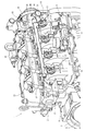
エンジン1は、天然ガス等の燃料ガスを空気に混合させて燃焼させる予混合燃焼方式によって駆動するものである。図1~図3に示す如く、エンジン1の上部に位置するシリンダヘッド2の左側面には吸気マニホールド3を設けている。シリンダヘッド2は、エンジン出力軸4(クランク軸)と複数の気筒(図示省略)とを内蔵したシリンダブロック5上に搭載している。シリンダヘッド2の右側面に排気マニホールド6を設けている。シリンダブロック5の前後両側面からエンジン出力軸4の前後突端側を突出させている。
エンジン1は、シリンダブロック5内に複数の気筒を直列に並べた構成になっている。シリンダブロック5内の各気筒は、シリンダヘッド2左側面側の吸気マニホールド3に連通している。詳細な図示は省略するが、吸気マニホールド3には、吸気スロットル弁11を介して、外気を除塵浄化して取り込むエアクリーナを接続している。また、シリンダヘッド2の上面左部(吸気マニホールド3側)には、各気筒内の予混合ガスに点火する点火装置12を各気筒に対応させて設けている。各点火装置12は、高電圧によって気筒内に火花放電を発生させ、気筒内の予混合ガスを燃焼させる。予混合ガスの燃焼によって各気筒内のピストンが往復動して、エンジン出力軸4を回転駆動させ、エンジン1の動力が発生する。
シリンダヘッド2の左側面に固定された吸気マニホールド3は、上記気筒数と同数の吸気枝管31を備えており、各吸気枝管31にガスインジェクタ13が挿設されている。気筒数と同数のガスインジェクタ13は、吸気マニホールド3上方で前後(エンジン出力軸4と平行)に延設された燃料ガス供給レール14と連結されている。燃料ガス供給レール14は、ボルト21により吸気マニホールド3に固定締結されている。
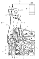
図4に示す如く、燃料ガス供給レール14のガス吸入口28は、ベーパライザ101を介して、ガスボンベ100と接続されている。ガスボンベ100には、液体の燃料ガスが貯蔵されており、ベーパライザ101によりガスボンベ100内の燃料ガスが気化された後、燃料ガス供給レール14を通じてガスインジェクタ13に供給される。ガスインジェクタ13が燃料ガスを吸気枝管31内に噴射することで、吸気マニホールド3内の新気と燃料ガスとが、吸気枝管31内で混合撹拌されて、シリンダブロック5内の各気筒における吸気ポートに供給される。また、シリンダブロック5内の各気筒は、吸気マニホールド3だけでなく、シリンダヘッド2右側面に固定された排気マニホールド6にも連通しており、各気筒における排気ポートを通じて排気マニホールド6に排気ガスが排気される。
シリンダヘッド2の右側上面は、ヘッドカバー15に覆われており、ヘッドカバー15内に弁腕室(図示省略)が形成されている。そして、シリンダヘッド2上面における、ヘッドカバー15で被覆されていない左側部分(シリンダヘッド2上面の露出部分)に、複数の点火装置12が前後に並べて挿設されている。また、シリンダヘッド2上面の右側部分では、吸気弁及び排気弁(図示省略)などがヘッドカバー15により覆われている。
ヘッドカバー15の後方部分には、各気筒の燃焼室などからシリンダヘッド2上面側に漏れ出たブローバイガスから潤滑油を分離するブローバイガス還元装置16が構成されている。ブローバイガス還元装置16は、ブローバイガス戻し管17を介して吸気マニホールド6と連通している。シリンダヘッド2及びシリンダブロック5に構成された燃焼室から漏れ出るブローバイガスは、ブローバイガス還元装置16及びブローバイガス戻し管17を通じて、吸気マニホールド6に供給されると、吸気スロットル弁11を介して吸気マニホールド6に供給される新気に合流する。そして、吸気マニホールド6で新気と合流したブローバイガスが上記燃焼室に再送される(還元される)ことで、ブローバイガスが大気に放出されないように構成している。
エンジン1は、シリンダヘッド2及びシリンダブロック5内とラジエータ(図示省略)等に冷却水を循環させる冷却水ポンプ19、及び、バッテリー(図示省略)を充電させるオルタネータ20を備えている。エンジン出力軸4の左突端部に伝動ベルト18等を介して冷却水ポンプ19及びオルタネータ20を連結している。エンジン出力軸4の回転動力を伝動ベルト18経由で冷却水ポンプ19に伝達して冷却水ポンプ19を駆動させ、シリンダヘッド2及びシリンダブロック5内とラジエータ等に冷却水を循環させる。一方、エンジン出力軸4の回転動力を伝動ベルト18経由でオルタネータ20に伝達してオルタネータ20を駆動させ、オルタネータ20で発電された電力によりバッテリー(図示省略)を充電させる。実施形態では、冷却水ポンプ19がエンジン1の後部上寄り部位に取り付けられており、オルタネータ20がエンジン1の後部右寄り部位に取り付けられている。
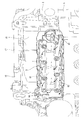
図5に示す如く、排気マニホールド6は水冷排気マニホールドで構成される。すなわち、排気マニホールド6は、シリンダヘッド2を介してシリンダブロック5内の各気筒に連通する排気ガス通路81と、排気ガス通路81を冷却する冷却水通路82を備える。エンジン1の各気筒から排出される排気ガスは、シリンダヘッド2の右側面から排出される。そして、破線矢印で示すように、排気ガスは、排気マニホールド6の排気ガス通路81に取り込まれて合流された後、排気マニホールド6前部の排気ガス出口から排出される。排気マニホールド6から排出される排気ガスは、排気ガス浄化装置(図示省略)等を介して外部に放出される。
冷却水通路82の上流部(前部)に、排気マニホールド6の下部前端部位に設けられる水入口83から冷却水が導入される。導入された冷却水は、実線矢印で示すように、排気ガス通路81の外壁に接しながら冷却水通路82内をエンジン1の後方へ向けて流れる。冷却水通路82の下流部(後部)に到達した冷却水は、排気マニホールド6の上部後端部位に設けられる水出口84から冷却水通路82外へ流出する。
図6に示すように、この実施形態では、排気マニホールド6の水入口83は、上流側冷却水経路91を介して、シリンダブロック5内部の冷却水通路に接続される。また、排気マニホールド6の水出口84は、下流側水経路92を介して冷却水ポンプ19に接続される。冷却水ポンプ19の駆動により、シリンダヘッド2(図1等参照)及びシリンダブロック5の内部の冷却水通路に冷却水が流通されて、エンジン1が冷却される。
また、シリンダブロック5内部の冷却水通路を流通する冷却水の一部は、上流側冷却水経路91及び排気マニホールド6の水入口83を介して冷却水通路82に導入され、排気ガス通路81内を流通する排気ガスを冷却する。冷却水通路82を通過した冷却水は、水出口84及び下流側水経路92を経て、冷却水ポンプ19に流入する。
図4及び図6に示すように、エンジン1の冷却水ポンプ19には、気化器用水出口85と気化器用水入口86が設けられる。気化器用水出口85は、気化器用の水送り経路93を介して、ベーパライザ101の水入口102に接続される。気化器用水入口86は、気化器用の水戻し経路94を介して、ベーパライザ101の水出口103に接続される。冷却水ポンプ19の駆動により、エンジン1の内部を通過した冷却水の一部がベーパライザ101に流通される。これにより、ベーパライザ101が加温されて、ベーパライザ101の凍結が防止されるとともに、ベーパライザ101での燃料気化が安定する。
ベーパライザ101の液化燃料ガス入口104は、配管からなる液化燃料ガス経路106を介して、燃料ガス源の一例としてのガスボンベ100に接続される。また、ベーパライザ101の燃料ガス出口105は、配管からなる燃料ガス経路107を介して、エンジン1のガス吸入口28に接続される。ガスボンベ100から供給される液化燃料ガスは、液化燃料ガス経路106を介して、液化燃料ガス入口104からベーパライザ101に導入され、ベーパライザ101で気化される。ベーパライザ101で気化された燃料ガスは、燃料ガス出口105から燃料ガス経路107を介してエンジン1のガス吸入口28に送られる。
図6に示すように、排気マニホールド6の水出口84を、エンジン1内部の冷却水流通経路を介さずに、ベーパライザ101の水入口102に接続するためのバイパス経路96が設けられている。バイパス経路96の一端(上流側端)は、排気マニホールド6の水出口84に連通する下流側水経路92の中途部に、例えば三方弁からなる切替弁95を介して接続される。また、バイパス経路96の他端(下流側端)は、ベーパライザ101の水入口102に連通する水送り経路93の中途部に、例えば三方弁からなる切替弁97を介して接続される。バイパス経路96及び切替弁95,97は、ベーパライザ101の水入口102を、エンジン1の気化器用水出口85又は排気マニホールド6の水出口84に接続する経路切替機構301を構成している。また、切替弁95は上流側弁の一例であり、切替弁97は下流側弁の一例である。
切替弁95,97は、例えば電磁弁又は電動弁であり、ECU(Engine Control Unit 又は Electronic Control Unit)からなる制御装置110に電気的に接続されている。制御装置110は、切替弁95,97を含むエンジン1の電気的補助装置を制御して、エンジン1の運転制御を行う。詳細は省略するが、制御装置110は、各種演算処理や制御を実行するCPU(Central Processing Unit)の他、各種データを予め固定的に記憶させたROM(Read Only Memory)、制御プログラムや各種データを書換可能に記憶するEEPROM(Electrically Erasable ROM)、制御プログラムや各種データを一時的に記憶するRAM(Random Access Memory)、時間計測用のタイマ、及び入出力インターフェイス等を有している。
この実施形態では、排気マニホールド6の水出口84をベーパライザ101に直接つなぐ際の切替弁95,97の制御に関連して、制御装置110の入力側に、油温センサ111、吸気温センサ112及び水温センサ113が電気的接続される。油温センサ111は、エンジン1内の潤滑油の温度を検出するものであり、この実施形態ではシリンダブロック5に取り付けられる。吸気温センサ112は、例えば温度計測機能付き吸気圧センサ(T-MAPS:Temperature-Manifold Absolute Pressure Sensor)で構成され、吸気マニホールド3内の吸気温度と吸気圧力を検出する。水温センサ113は、エンジン1内を流通する冷却水の温度を検出するものであり、この実施形態では冷却水ポンプ19に取り付けられる。
また、制御装置110の出力側には、切替弁95,97が電気的接続される。なお、図示は省略するが、制御装置110の入力側にはエンジン1に設けられる各種センサ等が電気的接続され、制御装置110の出力側にはエンジン1に設けられる各種装置等が電気的接続される。
次に、図7を参照しながら、エンジン装置200におけるベーパライザの凍結防止制御の流れについて説明する。制御装置110は、例えばエンジン1の低温始動時など、ベーパライザ101の凍結が予測されるときに、ベーパライザ101の水入口102を排気マニホールド6の水出口84にバイパス経路96を介して接続するように、切替弁95,97を制御する。
制御装置110は、エンジン1が始動されると(ステップS1:Yes)、水温センサ113の出力から計測される冷却水温度が所定水温しきい値よりも低いか否かを判定する(ステップS2)。冷却水温度が所定水温しきい値よりも低いとき(ステップS2:Yes)、エンジン1が冷間始動であることが予測される。このとき、制御装置110は、吸気温センサ112の出力から計測される吸気温度が所定吸気温しきい値よりも低いか否かを判定する(ステップS3)。
吸気温度が所定吸気温しきい値よりも低いとき(ステップS3:Yes)、エンジン装置200の周囲雰囲気が低温であることが予測される。このとき、制御装置110は、切替弁95,97を切り替えて、排気マニホールド6の水出口84をベーパライザ101の水入口102にバイパス経路96を介して接続する(ステップS4)。すなわち、切替弁95は、排気マニホールド6の水出口84をバイパス経路96に接続するとともに、排気マニホールド6の水出口84と冷却水ポンプ19の間の水経路を遮断する。また、切替弁97は、バイパス経路96を水送り経路93の中途部に接続するとともに、気化器用水出口85とベーパライザ101の間の水経路を遮断する。
バイパス経路96経由でのベーパライザ101への冷却水流通時には、排気マニホールド6の水出口84は、エンジン1内部の冷却水流通経路を介さずに、ベーパライザ101の水入口102に接続される。そして、エンジン始動後にエンジン1内部の冷却水よりも早く高温になりやすい排気マニホールド6内の冷却水がベーパライザ101に直接供給される。これにより、低温始動時など、ベーパライザ101の凍結が予測されるときに、ベーパライザ101の凍結を抑制でき、ベーパライザ101の凍結に起因するエンジンストールを防止して、エンジン始動性を向上できる。
エンジン1の駆動が継続され、油温センサ111の出力から計測される油温が所定油温しきい値を超えると(ステップS5:Yes)、制御装置110は、切替弁95,97を切り替えて、ベーパライザ101への冷却水流通経路を通常経路に切り替える(ステップS6)。すなわち、切替弁95は、排気マニホールド6の水出口84を冷却水ポンプ19に下流側水経路92を介して接続する。また、切替弁97は、冷却水用水出口85をベーパライザ101の水入口102に接続する。これにより、バイパス経路96に通じる水経路が遮断される。油温が所定油温しきい値を超えた状態では、エンジン1内の冷却水が十分に加温されているので、冷却水を排気マニホールド6からバイパス経路96経由でベーパライザ101に直接流通させなくても、気化器用水出口85から流出する冷却水でベーパライザ101の凍結を防止できる。
なお、エンジン1の始動後(ステップS1:Yes)、冷却水温度が所定水温しきい値以上のとき(ステップS2:No)や、吸気温度が所定吸気温しきい値よりも低いとき(ステップS3:Yes)には、制御装置110は、ベーパライザ101への冷却水流通経路が上記通常経路になるように、切替弁95,97を制御する(ステップS6)。
次に、図8及び図9を参照しながら、エンジン装置の他の実施形態について説明する。図8に示すように、この実施形態のエンジン装置201は、空燃比センサ114を備え、制御装置110が空燃比センサ114の出力に基づいてベーパライザ101の凍結を予測する点で、上記実施形態のエンジン装置200とは異なっている。エンジン装置201のその他の構成は、エンジン装置200と同様である。なお、図8での図示は省略されているが、エンジン装置201には空燃比センサ114以外にも各種センサが取り付けられており、例えば吸気温センサ112や水温センサ113(図6参照)などが取り付けられる。
空燃比センサ114は、排気ガス中の酸素濃度を検出するものであり、この実施形態では排気マニホールド6の排気ガス通路81に取り付けられる。空燃比センサ114は制御装置110に電気的接続されている。制御装置110は、空燃比センサ114の出力から、シリンダブロック5内の各気筒に供給される空気と燃料ガスとの混合気の空燃比を計測する。
図9を参照しながら、エンジン装置201におけるベーパライザの凍結防止制御の流れについて説明する。エンジン装置201でも、上記実施形態のエンジン装置200と同様に、制御装置110は、ベーパライザ101の凍結が予測されるときに、ベーパライザ101の水入口102を排気マニホールド6の水出口84にバイパス経路96を介して接続するように、切替弁95,97を制御する。
制御装置110は、エンジン1が始動されると(ステップS1:Yes)、空燃比センサ114の出力から計測される混合気の空燃比が所定空燃比しきい値よりも希薄傾向(リーン傾向)にあるか否かを判定する(ステップS11)。混合気の空燃比が所定空燃比しきい値よりも希薄傾向にあるとき(ステップS11:Yes)、ベーパライザ101が凍結傾向にあることが予測される。すなわち、ベーパライザ101が凍結傾向にあると液化燃料ガスが気化しにくくなり、空燃比が希薄(リーン)傾向になる特性を利用して、ベーパライザ101の凍結を予測する。そして、制御装置110は、切替弁95,97を切り替えて、排気マニホールド6の水出口84をベーパライザ101の水入口102にバイパス経路96を介して接続する(ステップS4)。エンジン装置201におけるステップS4での制御は、上記実施形態のエンジン装置200におけるステップS4(図7参照)での制御と同じである。
すなわち、エンジン装置201は、上記実施形態のエンジン装置200と同様にして、ベーパライザ101の凍結が予測されるときに、エンジン始動後にエンジン1内部の冷却水よりも早く高温になりやすい排気マニホールド6内の冷却水をベーパライザ101に直接供給する。これにより、低温始動時など、ベーパライザ101の凍結が予測されるときに、ベーパライザ101の凍結を抑制でき、ベーパライザ101の凍結に起因するエンジンストールを防止して、エンジン始動性を向上できる。
エンジン1の始動後(ステップS1:Yes)、混合気の空燃比が所定空燃比しきい値以下のとき(ステップS11:No)には、ベーパライザ101が凍結傾向になく、燃料ガスの気化が正常に行われていることが予測される。このとき、制御装置110は、ベーパライザ101への冷却水流通経路が上記通常経路になるように、切替弁95,97を制御する(ステップS12)。
制御装置110は、油温センサ111の出力から計測される油温が所定油温しきい値を超えるまで、混合気の空燃比を監視する(ステップS5:No、ステップS11)。エンジン1の駆動が継続され、油温が所定油温しきい値を超えると(ステップS5:Yes)、制御装置110は、ベーパライザ101への冷却水流通経路が上記通常経路になるように、切替弁95,97を制御する(ステップS13)。なお、油温が所定油温しきい値を超えたときに(ステップS5:Yes)、冷却水がバイパス経路96経由でベーパライザ101に供給されているときには、上記実施形態のエンジン装置200におけるステップS6(図7参照)での制御と同様にして、切替弁95,97を切り替えて、ベーパライザ101への冷却水流通経路を上記通常経路に切り替える。
次に、図10を参照しながら、エンジン装置のさらに他の実施形態について説明する。この実施形態のエンジン装置202は、図6に示すエンジン装置200と比較して、切替弁95,97に替えて、開閉弁115,117を備える。エンジン装置202のその他の構成は、エンジン装置200と同様である。
上流側弁の一例としての開閉弁115は、下流側水経路92とバイパス経路96の分岐位置よりも下流側で、下流側水経路92に設けられる。また、下流側弁の一例としての開閉弁117は、水送り経路93とバイパス経路96の分岐位置よりも上流側で、水送り経路93に設けられる。バイパス経路96及び開閉弁115,117は、ベーパライザ101の水入口102を、エンジン1の気化器用水出口85又は排気マニホールド6の水出口84に接続する経路切替機構302を構成している。
開閉弁115,117がともに開弁状態のときには、排気マニホールド6の冷却水通路82を流通する冷却水は、水出口84、下流側水経路92及び開閉弁115を介して冷却水ポンプ19に流入する一方で、気化器用水出口85から水送り経路93及び開閉弁117を介して冷却水がベーパライザ101の水入口102に流入する。他方、開閉弁115,117がともに閉弁状態のときには、排気マニホールド6の冷却水通路82を流通する冷却水は、水出口84、バイパス経路96及び水送り経路93を介してベーパライザ101の水入口102に流入する。
開閉弁115,117は、制御装置110に電気的接続されている。制御装置110は、図7を参照して説明したベーパライザ101の凍結防止制御の流れと同様にして、ベーパライザ101の凍結が予測されるときには、開閉弁115,117を切り替えて、ベーパライザ101の水入口102をバイパス経路96経由で排気マニホールド6の水出口84に接続する。これにより、低温始動時など、ベーパライザ101の凍結が予測されるときに、エンジン始動後にエンジン1内部の冷却水よりも早く高温になりやすい排気マニホールド6内の冷却水をベーパライザ101に直接供給できる。そして、ベーパライザ101の凍結に起因するエンジンストールを防止して、エンジン始動性を向上できる。
なお、切替弁95,97に替えて開閉弁115,117を備える構成は、図8を参照して説明したエンジン装置201に適用可能であることは言うまでもない。また、下流側水経路92に切替弁95を設ける一方で、水送り経路93に開閉弁117を設ける構成であってもよいし、下流側水経路92に開閉弁115を設ける一方で、水送り経路93に切替弁97を設ける構成であってもよい。
また、気化器用水出口85及び気化器用水入口86は、上記実施形態では冷却水ポンプ19に設けられているが、例えばシリンダヘッド2やシリンダブロック5など、エンジン1の他の構成部品に設けられてもよい。
図1~図6、図8及び図10に示すように、エンジン装置200,201,202は、エンジン1と、液化燃料ガスを貯留するガスボンベ100からの液化燃料ガスを気化させるベーパライザ101を備え、エンジン1の冷却水の一部をベーパライザ101に流通させるものであって、排気ガス通路81を冷却する冷却水通路82を有する水冷式の排気マニホールド6と、ベーパライザ101の水入口102を、エンジン1の気化器用水出口85、又は排気マニホールド6の水出口84に接続する経路切替機構301又は302を備えているので、ベーパライザ101の水入口102を排気マニホールド6の水出口84に接続することで、エンジン1始動後にエンジン1内部の冷却水よりも早く高温になりやすい排気マニホールド6内の冷却水をベーパライザ101に直接供給できる。これにより、低温始動時など、ベーパライザ101の凍結が予測されるときに、ベーパライザ101の凍結を抑制でき、ベーパライザ101の凍結に起因するエンジンストールを防止して、エンジン始動性を向上できる。
図6及び図7に示すように、エンジン装置200は、エンジン1の冷却水温度及び吸気温度がそれぞれ所定しきい値以下のときに、排気マニホールド6の水出口84がバイパス経路96を介してベーパライザ101の水入口102に接続されるようにした。エンジン装置200は、既存の水温センサ113、吸気温センサ112等を用いてベーパライザ101の凍結を予測でき、ベーパライザ101に専用の温度センサ等を設ける必要がないので、より安価な構成にして、エンジン装置200の製造コスト上昇を抑制できる。
図8及び図9に示すように、エンジン装置201は、エンジン1における燃料ガスと空気との混合気の空燃比が所定しきい値よりも希薄傾向にあるときに、排気マニホールド6の水出口84がバイパス経路96を介してベーパライザ101の水入口102に接続されるようにした。エンジン装置201は、ベーパライザ101が凍結傾向にあると液化燃料ガスが気化しにくくなり、空燃比が希薄(リーン)傾向になる特性を利用して、ベーパライザ101の凍結を予測できる。したがって、エンジン装置201は、ベーパライザ101に専用の温度センサ等を設ける必要がないので、より安価な構成にして、エンジン装置201の製造コスト上昇を抑制できる。
図1~図6、図8及び図10に示すように、エンジン装置200,201,202において、経路切替機構301,302は、水冷排気マニホールド6の水出口84をベーパライザ101の水入口102に接続するバイパス経路96と、水冷排気マニホールド6の水出口84をバイパス経路96側又はエンジン1側に切り替えて接続する下流側弁の例としての切替弁95又は開閉弁115と、ベーパライザ101の水入口102をバイパス経路96側又はエンジン1側に切り替えて接続する上流側弁の例としての切替弁97又は開閉弁117を備えている。したがって、エンジン装置200,201,202は、水冷排気マニホールド6と、1本のバイパス経路96と、2つの切替弁95,97又は開閉弁115,117という簡単な構成を既存の構成に追加するだけで、水冷排気マニホールド6内の冷却水をベーパライザ101に直接供給できるようになる。
本願発明は、前述の実施形態に限らず、様々な態様に具体化できる。各部の構成は図示の実施形態に限定されるものではなく、本願発明の趣旨を逸脱しない範囲で種々変更が可能である。
1 エンジン
6 排気マニホールド(水冷排気マニホールド)
85 気化器用水出口
96 バイパス経路
100 ガスボンベ(燃料ガス源)
101 ベーパライザ(気化器)
102 水入口
200,201,202 エンジン装置
301,302 経路切替機構
6 排気マニホールド(水冷排気マニホールド)
85 気化器用水出口
96 バイパス経路
100 ガスボンベ(燃料ガス源)
101 ベーパライザ(気化器)
102 水入口
200,201,202 エンジン装置
301,302 経路切替機構
Claims (4)
- エンジンと、液化燃料ガスを貯留する燃料ガス源からの液化燃料ガスを気化させる気化器を備え、エンジンの冷却水の一部を気化器に流通させるエンジン装置において、
排気ガス通路を冷却する冷却水通路を有する水冷排気マニホールドと、
前記気化器の水入口を、前記エンジンの気化器用水出口、又は前記水冷排気マニホールドの水出口に接続する経路切替機構を備えているエンジン装置。 - 前記エンジンの冷却水温度及び吸気温度がそれぞれ所定しきい値以下のときに、前記水冷排気マニホールドの水出口がバイパス経路を介して前記気化器の水入口に接続される請求項1に記載のエンジン装置。
- 前記エンジンにおける燃料ガスと空気との混合気の空燃比が所定しきい値よりも希薄傾向にあるときに、前記水冷排気マニホールドの水出口がバイパス経路を介して前記気化器の水入口に接続される請求項1に記載のエンジン装置。
- 前記経路切替機構は、前記水冷排気マニホールドの水出口を前記気化器の水入口に接続するバイパス経路と、前記水冷排気マニホールドの水出口を前記バイパス経路側又は前記エンジン側に切り替えて接続する下流側弁と、前記気化器の水入口を前記バイパス経路側又は前記エンジン側に切り替えて接続する上流側弁を備えている請求項1に記載のエンジン装置。
Priority Applications (1)
| Application Number | Priority Date | Filing Date | Title |
|---|---|---|---|
| US16/498,833 US20200063653A1 (en) | 2017-03-29 | 2018-01-29 | Engine device |
Applications Claiming Priority (2)
| Application Number | Priority Date | Filing Date | Title |
|---|---|---|---|
| JP2017-066460 | 2017-03-29 | ||
| JP2017066460A JP6670266B2 (ja) | 2017-03-29 | 2017-03-29 | エンジン装置 |
Publications (1)
| Publication Number | Publication Date |
|---|---|
| WO2018179775A1 true WO2018179775A1 (ja) | 2018-10-04 |
Family
ID=63674944
Family Applications (1)
| Application Number | Title | Priority Date | Filing Date |
|---|---|---|---|
| PCT/JP2018/002708 Ceased WO2018179775A1 (ja) | 2017-03-29 | 2018-01-29 | エンジン装置 |
Country Status (3)
| Country | Link |
|---|---|
| US (1) | US20200063653A1 (ja) |
| JP (1) | JP6670266B2 (ja) |
| WO (1) | WO2018179775A1 (ja) |
Families Citing this family (2)
| Publication number | Priority date | Publication date | Assignee | Title |
|---|---|---|---|---|
| JP2020101184A (ja) * | 2020-02-28 | 2020-07-02 | ヤンマーパワーテクノロジー株式会社 | エンジン装置 |
| US11306647B1 (en) | 2021-04-28 | 2022-04-19 | Caterpillar Inc. | Combustion gas leak detection strategy |
Citations (4)
| Publication number | Priority date | Publication date | Assignee | Title |
|---|---|---|---|---|
| JPS48102424U (ja) * | 1972-03-02 | 1973-12-01 | ||
| JPS54117436U (ja) * | 1978-02-03 | 1979-08-17 | ||
| JPS643066U (ja) * | 1987-05-25 | 1989-01-10 | ||
| WO2011037567A1 (en) * | 2009-09-24 | 2011-03-31 | Rowley Gerald W | Fuel vaporizer for fuel injected engines |
-
2017
- 2017-03-29 JP JP2017066460A patent/JP6670266B2/ja active Active
-
2018
- 2018-01-29 US US16/498,833 patent/US20200063653A1/en not_active Abandoned
- 2018-01-29 WO PCT/JP2018/002708 patent/WO2018179775A1/ja not_active Ceased
Patent Citations (4)
| Publication number | Priority date | Publication date | Assignee | Title |
|---|---|---|---|---|
| JPS48102424U (ja) * | 1972-03-02 | 1973-12-01 | ||
| JPS54117436U (ja) * | 1978-02-03 | 1979-08-17 | ||
| JPS643066U (ja) * | 1987-05-25 | 1989-01-10 | ||
| WO2011037567A1 (en) * | 2009-09-24 | 2011-03-31 | Rowley Gerald W | Fuel vaporizer for fuel injected engines |
Also Published As
| Publication number | Publication date |
|---|---|
| JP2018168747A (ja) | 2018-11-01 |
| JP6670266B2 (ja) | 2020-03-18 |
| US20200063653A1 (en) | 2020-02-27 |
Similar Documents
| Publication | Publication Date | Title |
|---|---|---|
| US6644272B2 (en) | Diesel engine | |
| US10746086B2 (en) | Systems and methods for reducing engine overheating using liquid fuel | |
| RU2647162C2 (ru) | Топливная система для двигателя внутреннего сгорания и способ ее эксплуатации (варианты) | |
| JPH06129322A (ja) | 高圧噴射式エンジンの燃料圧力制御方法 | |
| JP7238479B2 (ja) | 凝縮水処理装置 | |
| JP5040556B2 (ja) | 内燃機関の二次空気供給装置 | |
| BR102013004382A2 (pt) | Sistema de gerenciamento térmico da alimentação de combustível em mototres de combustão interna | |
| JP6670266B2 (ja) | エンジン装置 | |
| BR102016021505A2 (pt) | aparelho de controle para motor de combustão interna | |
| JP2020143592A (ja) | 凝縮水処理装置 | |
| JP2020101184A (ja) | エンジン装置 | |
| JP4042274B2 (ja) | 内燃機関の燃料噴射弁加熱装置 | |
| JP2018168748A (ja) | エンジン装置 | |
| JP6525839B2 (ja) | 内燃機関の制御装置 | |
| JP4134592B2 (ja) | 蓄熱装置を備えた内燃機関 | |
| JP2013087758A (ja) | 内燃機関冷却制御装置 | |
| JP5383247B2 (ja) | ガスエンジン駆動機器 | |
| WO2010074354A1 (ja) | 内燃機関における燃費向上装置 | |
| JP2016183583A (ja) | 内燃機関の制御装置 | |
| JP4172296B2 (ja) | 内燃機関の制御装置 | |
| JP6830455B2 (ja) | 内燃機関 | |
| JP2008286101A (ja) | 液化ガス燃料供給装置 | |
| JPH11303696A (ja) | 燃焼式ヒータの出力制御装置 | |
| JP2007285130A (ja) | 内燃機関 | |
| JP2007326464A (ja) | ハイブリッド車両の制御装置 |
Legal Events
| Date | Code | Title | Description |
|---|---|---|---|
| 121 | Ep: the epo has been informed by wipo that ep was designated in this application |
Ref document number: 18777125 Country of ref document: EP Kind code of ref document: A1 |
|
| NENP | Non-entry into the national phase |
Ref country code: DE |
|
| 122 | Ep: pct application non-entry in european phase |
Ref document number: 18777125 Country of ref document: EP Kind code of ref document: A1 |