WO2018179196A1 - Led display device and method for correcting luminance thereof - Google Patents
Led display device and method for correcting luminance thereof Download PDFInfo
- Publication number
- WO2018179196A1 WO2018179196A1 PCT/JP2017/013155 JP2017013155W WO2018179196A1 WO 2018179196 A1 WO2018179196 A1 WO 2018179196A1 JP 2017013155 W JP2017013155 W JP 2017013155W WO 2018179196 A1 WO2018179196 A1 WO 2018179196A1
- Authority
- WO
- WIPO (PCT)
- Prior art keywords
- luminance
- unit
- led
- display unit
- measurement
- Prior art date
Links
Images


Classifications
-
- G—PHYSICS
- G09—EDUCATION; CRYPTOGRAPHY; DISPLAY; ADVERTISING; SEALS
- G09G—ARRANGEMENTS OR CIRCUITS FOR CONTROL OF INDICATING DEVICES USING STATIC MEANS TO PRESENT VARIABLE INFORMATION
- G09G3/00—Control arrangements or circuits, of interest only in connection with visual indicators other than cathode-ray tubes
- G09G3/20—Control arrangements or circuits, of interest only in connection with visual indicators other than cathode-ray tubes for presentation of an assembly of a number of characters, e.g. a page, by composing the assembly by combination of individual elements arranged in a matrix no fixed position being assigned to or needed to be assigned to the individual characters or partial characters
- G09G3/2007—Display of intermediate tones
- G09G3/2014—Display of intermediate tones by modulation of the duration of a single pulse during which the logic level remains constant
-
- G—PHYSICS
- G09—EDUCATION; CRYPTOGRAPHY; DISPLAY; ADVERTISING; SEALS
- G09G—ARRANGEMENTS OR CIRCUITS FOR CONTROL OF INDICATING DEVICES USING STATIC MEANS TO PRESENT VARIABLE INFORMATION
- G09G3/00—Control arrangements or circuits, of interest only in connection with visual indicators other than cathode-ray tubes
- G09G3/20—Control arrangements or circuits, of interest only in connection with visual indicators other than cathode-ray tubes for presentation of an assembly of a number of characters, e.g. a page, by composing the assembly by combination of individual elements arranged in a matrix no fixed position being assigned to or needed to be assigned to the individual characters or partial characters
- G09G3/22—Control arrangements or circuits, of interest only in connection with visual indicators other than cathode-ray tubes for presentation of an assembly of a number of characters, e.g. a page, by composing the assembly by combination of individual elements arranged in a matrix no fixed position being assigned to or needed to be assigned to the individual characters or partial characters using controlled light sources
- G09G3/30—Control arrangements or circuits, of interest only in connection with visual indicators other than cathode-ray tubes for presentation of an assembly of a number of characters, e.g. a page, by composing the assembly by combination of individual elements arranged in a matrix no fixed position being assigned to or needed to be assigned to the individual characters or partial characters using controlled light sources using electroluminescent panels
- G09G3/32—Control arrangements or circuits, of interest only in connection with visual indicators other than cathode-ray tubes for presentation of an assembly of a number of characters, e.g. a page, by composing the assembly by combination of individual elements arranged in a matrix no fixed position being assigned to or needed to be assigned to the individual characters or partial characters using controlled light sources using electroluminescent panels semiconductive, e.g. using light-emitting diodes [LED]
-
- H—ELECTRICITY
- H01—ELECTRIC ELEMENTS
- H01L—SEMICONDUCTOR DEVICES NOT COVERED BY CLASS H10
- H01L33/00—Semiconductor devices with at least one potential-jump barrier or surface barrier specially adapted for light emission; Processes or apparatus specially adapted for the manufacture or treatment thereof or of parts thereof; Details thereof
-
- G—PHYSICS
- G09—EDUCATION; CRYPTOGRAPHY; DISPLAY; ADVERTISING; SEALS
- G09G—ARRANGEMENTS OR CIRCUITS FOR CONTROL OF INDICATING DEVICES USING STATIC MEANS TO PRESENT VARIABLE INFORMATION
- G09G2300/00—Aspects of the constitution of display devices
- G09G2300/04—Structural and physical details of display devices
- G09G2300/0404—Matrix technologies
- G09G2300/0413—Details of dummy pixels or dummy lines in flat panels
-
- G—PHYSICS
- G09—EDUCATION; CRYPTOGRAPHY; DISPLAY; ADVERTISING; SEALS
- G09G—ARRANGEMENTS OR CIRCUITS FOR CONTROL OF INDICATING DEVICES USING STATIC MEANS TO PRESENT VARIABLE INFORMATION
- G09G2320/00—Control of display operating conditions
- G09G2320/02—Improving the quality of display appearance
- G09G2320/0233—Improving the luminance or brightness uniformity across the screen
-
- G—PHYSICS
- G09—EDUCATION; CRYPTOGRAPHY; DISPLAY; ADVERTISING; SEALS
- G09G—ARRANGEMENTS OR CIRCUITS FOR CONTROL OF INDICATING DEVICES USING STATIC MEANS TO PRESENT VARIABLE INFORMATION
- G09G2320/00—Control of display operating conditions
- G09G2320/02—Improving the quality of display appearance
- G09G2320/029—Improving the quality of display appearance by monitoring one or more pixels in the display panel, e.g. by monitoring a fixed reference pixel
-
- G—PHYSICS
- G09—EDUCATION; CRYPTOGRAPHY; DISPLAY; ADVERTISING; SEALS
- G09G—ARRANGEMENTS OR CIRCUITS FOR CONTROL OF INDICATING DEVICES USING STATIC MEANS TO PRESENT VARIABLE INFORMATION
- G09G2320/00—Control of display operating conditions
- G09G2320/04—Maintaining the quality of display appearance
- G09G2320/041—Temperature compensation
-
- G—PHYSICS
- G09—EDUCATION; CRYPTOGRAPHY; DISPLAY; ADVERTISING; SEALS
- G09G—ARRANGEMENTS OR CIRCUITS FOR CONTROL OF INDICATING DEVICES USING STATIC MEANS TO PRESENT VARIABLE INFORMATION
- G09G2320/00—Control of display operating conditions
- G09G2320/04—Maintaining the quality of display appearance
- G09G2320/043—Preventing or counteracting the effects of ageing
- G09G2320/045—Compensation of drifts in the characteristics of light emitting or modulating elements
-
- G—PHYSICS
- G09—EDUCATION; CRYPTOGRAPHY; DISPLAY; ADVERTISING; SEALS
- G09G—ARRANGEMENTS OR CIRCUITS FOR CONTROL OF INDICATING DEVICES USING STATIC MEANS TO PRESENT VARIABLE INFORMATION
- G09G2320/00—Control of display operating conditions
- G09G2320/04—Maintaining the quality of display appearance
- G09G2320/043—Preventing or counteracting the effects of ageing
- G09G2320/048—Preventing or counteracting the effects of ageing using evaluation of the usage time
-
- G—PHYSICS
- G09—EDUCATION; CRYPTOGRAPHY; DISPLAY; ADVERTISING; SEALS
- G09G—ARRANGEMENTS OR CIRCUITS FOR CONTROL OF INDICATING DEVICES USING STATIC MEANS TO PRESENT VARIABLE INFORMATION
- G09G2360/00—Aspects of the architecture of display systems
- G09G2360/14—Detecting light within display terminals, e.g. using a single or a plurality of photosensors
- G09G2360/145—Detecting light within display terminals, e.g. using a single or a plurality of photosensors the light originating from the display screen
Definitions
- the present invention relates to an LED device and a luminance correction method thereof, and more particularly to an LED display device that displays video information by controlling blinking of a plurality of LEDs (Light Emitting Diodes) arranged in a matrix and a luminance correction method thereof. .
- LEDs Light Emitting Diodes
- Display devices that use LEDs are often used for outdoor and indoor advertising display, etc., due to the technological development and cost reduction of LEDs. These LED display devices have so far mainly displayed moving images of natural images and animations. In recent years, the viewing distance has become shorter as the pixel pitch becomes narrower, so it has been used for conference rooms, monitoring applications, and the like. Especially in surveillance applications, personal computer images close to still images are often displayed. However, since the luminance of the LED decreases as the lighting time becomes longer, the luminance decrease rate of each LED differs depending on the content of the image, resulting in luminance variation and color variation for each pixel.
- a method of detecting luminance of an LED display unit and correcting luminance data is known. Also, a method is known in which the LED lighting time is integrated and the luminance is corrected based on the luminance correction coefficient that has already been measured according to the integrated time (see, for example, Patent Documents 1 and 2).
- the operation stop time is as short as possible. However, if the operation stop time is shortened, the correction accuracy does not improve, resulting in luminance variations and color variations, and the image quality of the LED display section. There was a problem that decreased. In addition, there is a problem that it is necessary to replace the LED module with a new one in order to solve the deterioration in image quality.
- the present invention has been made to solve the above-described problems, and an LED display device that corrects the luminance of each LED element so as to suppress deterioration in image quality due to variations in the characteristics of the LED elements, and the luminance thereof.
- the purpose is to provide a correction method.
- An LED display device drives a plurality of LED elements included in the display unit based on a display unit including at least one display module including a plurality of LED elements and a video signal received from the video signal processing unit.
- a second aging display unit comprising at least one measurement LED element, a second drive unit for driving the measurement LED elements provided in the first aging display unit and the second aging display unit, and a first aging
- a luminance measuring unit for measuring the luminance of the LED element for measurement provided in the display unit and the second aging display unit, the first aging display unit and the second aging
- a second temperature detection unit that detects each temperature of the display unit; a cumulative lighting time storage unit that stores a cumulative lighting time for each of the plurality of LED elements included in the display unit; a first aging display unit;
- a luminance reduction rate storage unit
- a luminance correction coefficient calculation unit that calculates a luminance correction coefficient, and each of the plurality of LED elements based on the luminance correction coefficient
- a luminance correction unit that controls the first drive unit to correct the luminance, and the luminance correction coefficient calculation unit includes the temperature detected by the first temperature detection unit and the second temperature detection unit. Parts is based on the detected temperature, correcting the respective luminance correction coefficient of the plurality of LED elements included in the display unit.
- a brightness correction method is a brightness correction method for an LED display device, and the LED display device includes a display unit including at least one display module including a plurality of LED elements, and an image received from a video signal processing unit.
- a first aging display unit including at least one measurement LED element equivalent to a first drive unit that drives a plurality of LED elements provided in the display unit based on a signal, a first temperature detection unit, and the LED element
- a second aging display unit including at least one measurement LED element equivalent to the LED element, and a second drive for driving the measurement LED element provided in the first aging display unit and the second aging display unit
- the method includes (a) a step in which the first temperature detection unit detects the temperature of the display unit, and (b) a measurement LED provided in the first aging display unit and the second aging display unit by the luminance measurement unit. A step of measuring the luminance of the element; (c) a step in which the second temperature detection unit detects the respective temperatures of the first aging display unit and the second aging display unit; and (d) storage of accumulated lighting time. A step in which the unit stores the cumulative lighting time for each of the plurality of LED elements provided in the display unit, and (e) a measurement in which the luminance reduction rate storage unit is provided in the first aging display unit and the second aging display unit.
- the luminance correction coefficient is corrected in consideration of the difference in luminance reduction rate due to the temperature difference between the display unit and the first and second aging display units.
- first and second aging display units are arranged. Thus, even if one of the aging display units breaks down, the luminance correction of the display unit can be performed correctly by using the accurate luminance reduction rate and temperature obtained from the other aging display unit. Therefore, the luminance of the display unit can be kept stable and uniform during long-term operation.
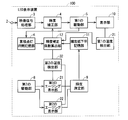
- FIG. 3 is a functional block diagram of the LED display device according to Embodiment 1.
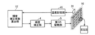
- FIG. 3 is a detailed block diagram around the display unit of the LED display device according to Embodiment 1.
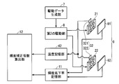
- FIG. 3 is a detailed block diagram of the periphery of a first aging display unit and a second aging display unit of the LED display device according to Embodiment 1.
- 2 is a hardware configuration diagram of the LED display device according to Embodiment 1.
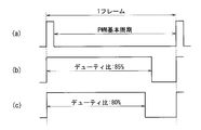
- FIG. 4 is a diagram for explaining a driving method of the LED display device according to Embodiment 1.
- FIG. It is a figure which shows the relationship between the accumulation lighting time of a green LED element, and a luminance fall rate.
- FIG. 6 is a diagram illustrating a temperature correction function of the LED display device according to Embodiment 1.
- FIG. 4 is a flowchart showing a luminance correction operation of the LED display device according to Embodiment 1.
- FIG. 5 is a diagram showing a luminance correction operation of the LED display device according to Embodiment 1.
- 6 is a diagram showing another example of the luminance correction operation of the LED display device according to Embodiment 1.
- FIG. 6 is a detailed block diagram around a display unit of an LED display device according to Embodiment 3.
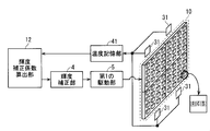
- FIG. 1 is a functional block diagram of the LED display device 100 according to the first embodiment.
- FIG. 2 is a more detailed block diagram around the display unit 10.
- FIG. 3 is a more detailed block diagram around the first and second aging display units 21 and 22.
- the LED display device 100 includes a display unit 10, a first drive unit 5, a first temperature detection unit 31, first and second aging display units 21 and 22, and a second drive unit. 8, a luminance measurement unit 9, a second temperature detection unit 32, a luminance decrease rate storage unit 11, a cumulative lighting time storage unit 6, a luminance correction coefficient calculation unit 12, and a luminance correction unit 4.
- the display module provided in the display unit 10 includes a plurality of unit pixels arranged in a matrix of M rows and N columns.
- the M rows and N columns are, for example, 4 rows and 4 columns as shown in FIG. 2, but are not limited thereto.
- three LED elements of red (R), green (G), and blue (B) are arranged.
- the first temperature detection unit 31 individually detects the temperature of each LED element provided in the display unit 10. The temperature detected by the first temperature detection unit 31 is stored in the temperature storage unit 41.
- the display unit 10 includes one display module.
- the display unit 10 may include a plurality of display modules in order to configure a large screen. A configuration including a plurality of display modules will be described in Embodiment 3.
- the first driving unit 5 drives a plurality of LED elements provided in the display unit 10 based on the video signal received from the video signal processing unit 3.
- a video signal is input to the input terminal 2 of the video signal processing unit 3 from the outside of the LED display device 100.
- the video signal processing unit 3 performs processing for selecting a region necessary for display, gamma correction processing, and the like on a video signal input from the outside.
- the data stored in the cumulative lighting time storage unit 6 is the cumulative time that each LED element included in the display unit 10 is lit, and is accumulated every certain unit time. For example, if the unit time is one hour and the luminance is 10%, the lighting time of 0.1 hour is stored in the cumulative lighting time storage unit 6 every hour.
- what was acquired for every unit time may be used for a duty ratio.
- the average duty ratio in unit time may be sufficient. A current control method based on the duty ratio will be described later.
- Each of the first and second aging display units 21 and 22 includes, for example, four unit pixels arranged in two rows and two columns as shown in FIG. Each unit pixel is provided with one LED element for measurement of red, green, and blue. Each of the first and second aging display units 21 and 22 may be provided with at least one unit pixel, but the measurement LED element is measured by providing a plurality of unit pixels. Increased brightness and temperature measurements. Therefore, by taking the average of the measured values, it is possible to suppress the variation in the measured values.
- the LED elements for measurement of each color are LED elements equivalent to the LED elements of each color provided in the display unit 10.
- an equivalent LED element means an LED element manufactured with the same specifications.
- the LED elements provided in the display unit 10 and the measurement LED elements provided in each of the first and second aging display units 21 and 22 are preferably in the same production lot.
- the second temperature detection unit 32 includes a temperature detection unit 321 for the first aging display unit 21 and a temperature detection unit 322 for the second aging display unit 22.
- the temperature detection unit 321 individually detects the temperature of each measurement LED element provided in the first aging display unit 21.
- the temperature detection unit 322 individually detects the temperature of each measurement LED element provided in the second aging display unit 22.
- the temperature detected by the second temperature detection unit 32 is stored in the temperature storage unit 42.
- the luminance measuring unit 9 includes a luminance measuring unit 91 for the first aging display unit 21 and a luminance measuring unit 92 for the second aging display unit 22.
- the luminance measuring unit 91 measures the luminance of the measurement LED element provided in the first aging display unit 21.
- the luminance measuring unit 92 measures the luminance of the measurement LED element provided in the second aging display unit 22.
- the 2nd drive part 8 drives the LED element for a measurement with which each of the 1st, 2nd aging display parts 21 and 22 is equipped.
- the luminance reduction rate storage unit 11 stores the relationship between the cumulative lighting time of the measurement LED element and the luminance reduction rate of the measurement LED element based on the measurement result of the luminance measurement unit 9.
- the luminance decrease rate storage unit 11 stores the above relationship for both the first and second aging display units 21 and 22.
- the luminance correction coefficient calculation unit 12 calculates a luminance correction coefficient for each of the LED elements included in the display unit 10 with reference to the cumulative lighting time storage unit 6 and the luminance decrease rate storage unit 11. A method for calculating the luminance correction coefficient will be described later.
- the luminance correction coefficient calculation unit 12 further includes a luminance correction coefficient for each of the LED elements included in the display unit 10 based on the temperature detected by the first temperature detection unit 31 and the temperature detected by the second temperature detection unit 32. Correct. The correction method will be described later.
- the luminance correction unit 4 corrects the output of the video signal processing circuit unit 3 in accordance with the luminance correction coefficient calculated by the luminance correction coefficient calculation unit 12.
- the luminance correction coefficient calculation unit 12 determines whether the first and second aging display units 21 and 22 are normal or faulty, and the luminance reduction rate and temperature of the normal aging display unit.
- the luminance correction coefficient is calculated with reference to FIG.
- the luminance correction coefficient calculation unit 12 refers to, for example, the luminance reduction rate and temperature of the first aging display unit 21 and calculates the luminance correction coefficient. calculate.
- the luminance correction coefficient calculation unit 12 refers to each of the first and second aging display units 21 and 22 and performs two types.
- the luminance correction coefficient may be calculated. In this case, one of the luminance correction coefficients is used for the luminance correction performed by the luminance correction unit 4.
- LED elements provided in the first display unit 10 are hereinafter simply referred to as LED elements.
- FIG. 4 is a hardware configuration diagram of the LED display device 100.
- the LED display device 100 includes an input interface HW1, a processing circuit HW2, a memory HW3, a storage device HW4, a first drive circuit HW5, a display device HW6, a first temperature detection device HW7, a second A drive circuit HW8, a first aging display device HW9, a second aging display device HW10, a luminance measurement device HW11, and a first temperature detection device HW12 are provided.
- Each of the above components is connected to each other by a bus.
- the video signal processing unit 3, the luminance correction coefficient calculation unit 12, and the luminance correction unit 4 are realized by the processing circuit HW2.
- the processing circuit HW2 may be dedicated hardware. Further, the processing circuit HW2 may be a CPU (Central Processing Unit, central processing unit, processing unit, arithmetic unit, microprocessor, microcomputer, processor, DSP) that executes a program stored in the memory HW3.
- CPU Central Processing Unit, central processing unit, processing unit, arithmetic unit, microprocessor, microcomputer, processor, DSP
- the processing circuit HW2 corresponds to, for example, a single circuit, a composite circuit, a programmed processor, a parallel programmed processor, an ASIC, an FPGA, or a combination thereof.
- the functions of each unit of the video signal processing unit 3, the luminance correction coefficient calculation unit 12, and the luminance correction unit 4 may be realized by the processing circuit HW2 provided individually, or the functions of the respective units may be integrated into one processing circuit HW2. It may be realized.
- the processing circuit HW2 When the processing circuit HW2 is a CPU, the functions of the video signal processing unit 3, the luminance correction coefficient calculation unit 12, and the luminance correction unit 4 are realized by software, firmware, or a combination of software and firmware.
- Software and firmware are described as programs and stored in the memory HW3.
- the processing circuit HW2 reads out and executes the program stored in the memory HW3, thereby realizing the function of each unit. These programs can be said to cause a computer to execute the procedures and methods of the video signal processing unit 3, the luminance correction coefficient calculation unit 12, and the luminance correction unit 4.
- the memory HW3 is, for example, a nonvolatile or volatile semiconductor memory such as RAM, ROM, flash memory, EPROM, EEPROM, magnetic disk, flexible disk, optical disk, compact disk, mini disk, DVD, etc. Applicable.
- the processing circuit can realize the functions described above by hardware, software, firmware, or a combination thereof.
- the first drive unit 5 is realized by the first drive circuit HW5.
- the first drive circuit HW5 may be dedicated hardware.
- the first drive circuit HW5 may be a CPU that executes a program stored in the memory HW3.
- the first drive circuit HW5 is dedicated hardware
- the first drive circuit HW5 is, for example, a single circuit, a composite circuit, a programmed processor, a parallel programmed processor, an ASIC, an FPGA, or the like. The combination is applicable.
- the first drive circuit HW5 is a CPU
- the function of the first drive unit 5 is realized by software, firmware, or a combination of software and firmware.
- Software and firmware are described as programs and stored in the memory HW3.
- the first drive circuit HW5 reads out and executes the program stored in the memory HW3, thereby realizing the function of the first drive unit 5.
- the second drive unit 8 is realized by the second drive circuit HW8.
- the second drive circuit HW8 may be dedicated hardware.
- the second drive circuit HW8 may be a CPU that executes a program stored in the memory HW3.
- the second drive circuit HW8 is dedicated hardware
- the second drive circuit HW8 is, for example, a single circuit, a composite circuit, a programmed processor, a parallel programmed processor, an ASIC, an FPGA, or the like. The combination is applicable.
- the second drive circuit HW8 is a CPU
- the function of the second drive unit 8 is realized by software, firmware, or a combination of software and firmware. Software and firmware are described as programs and stored in the memory HW3.
- the second drive circuit HW8 realizes the function of the second drive unit 8 by reading and executing the program stored in the memory HW3.
- the display unit 10 is realized by the display device HW6.
- the configuration of the display device HW6 corresponds to the configuration of the display unit 10 described above.
- the first aging display unit 21 is realized by the first aging display device HW9.
- the configuration of the first aging display device HW9 corresponds to the configuration of the first aging display unit 21 described above.
- the second aging display unit 22 is realized by the second aging display device HW10.
- the configuration of the first aging display device HW10 corresponds to the configuration of the second aging display unit 22 described above.
- the luminance measuring unit 9 is realized by a luminance measuring device HW11.
- the luminance measuring device HW11 includes as many photodiodes as the number of measurement LED elements. By using a photodiode capable of measuring a wavelength in the visible range, it is possible to measure the luminance of the LED element for measurement of each color.
- the first and second temperature detectors 31 and 32 are realized by the first temperature detectors HW7 and HW12, respectively.
- the first and second temperature detection devices detect the temperature of each LED element using, for example, a thermocouple.
- the first temperature detection device HW7 may estimate the temperature of each LED element by measuring the forward voltage of each LED element.
- the second temperature detection device HW12 is the same as the first temperature detection device HW7.
- the cumulative lighting time storage unit 6, the luminance decrease rate storage unit 11, and the temperature storage units 41 and 42 are realized by the storage device HW4.
- the storage device HW4 is, for example, a nonvolatile memory.
- the input terminal 2 of the video signal processing unit 3 is realized by the input interface HW1.
- FIG. 5 is a diagram illustrating an example of PWM driving.
- each LED element is driven by applying a pulse synchronized with the period of one frame period of the video signal.
- the pulse width is shorter than one frame period.
- the ratio of the pulse width to one frame of the video signal is called the duty ratio.
- FIG. 5B shows a case of driving with a duty ratio of 85%.
- FIG. 5C shows a case of driving with a duty ratio of 80%.
- the pulse width is obtained by multiplying the PWM basic cycle by the duty ratio.
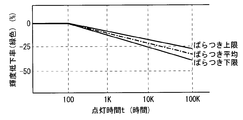
- FIG. 6 is a diagram showing the relationship between the cumulative lighting time of the green LED element and the luminance reduction rate. As shown in FIG. 6, the brightness of the LED element decreases with the cumulative lighting time. In general, the luminance reduction rate of the LED element is likely to vary due to the difference in LED manufacturing lot and BIN code, as shown in FIG. Conventionally, the luminance reduction rate is obtained by prior measurement. In the first embodiment, the first and second aging display units 21 and 22 are provided to measure the luminance reduction rate in real time. .
- the second drive unit 8 drives the measurement LED element with the maximum duty ratio in the display unit 10. That is, the display pattern of the maximum duty ratio is input to the second drive unit 8 from the drive data generation unit 7, and the second drive unit 8 is based on this display pattern and the first and second aging display units. 21 and 22 are driven.
- the maximum duty ratio in the display unit 10 is the maximum duty ratio among the duty ratios in which the LED elements included in the display unit 10 are driven.
- the measurement LED elements provided in the first and second aging display units 21 and 22 are also driven at a duty ratio of 100%. Accordingly, the cumulative lighting time of the LED elements for measurement provided in each of the first and second aging display units 21 and 22 can be set to be equal to or longer than the cumulative lighting time of all the LED elements provided in the display unit 10. .
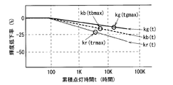
- FIG. 7 is a diagram showing the relationship between the cumulative lighting time of the first and second LED aging display sections 21 and 21 and the luminance reduction rate.
- the luminance measuring unit 9 measures the luminance of each color measuring LED element in real time, and stores the luminance reduction rate in the luminance reduction rate storage unit 11.
- the luminance reduction rate storage unit 11 stores the relationship between the cumulative lighting time of the LED elements for measurement of each color up to the current time and the luminance reduction rate.
- the luminance reduction rates of the red, green, and blue measuring LED elements are respectively expressed as kr (t), kg (t), and kb (t) as a function of the cumulative lighting time t.
- the brightness reduction rate with respect to the cumulative lighting time of the LED is generally affected by the temperature during driving. Therefore, by taking into account the difference between the temperature of the LED element provided in the display unit 10 and the temperature of the LED element for measurement provided in the first aging display unit 21 or the second aging display unit 22, it is possible to obtain a more accurate luminance. Correction can be realized.
- the temperatures of red, green, and blue LED elements in a certain pixel provided in the display unit 10 are tr, tg, and tb, respectively. Further, the temperatures of the red, green, and blue measuring LED elements provided in the first aging display unit 21 or the second aging display unit 22 are respectively tre, tge, and tbe. Temperature differences Tr, Tg, and Tb between the LED elements of the respective colors and the LED elements for measurement of the respective colors are expressed by Expression (1).
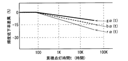
- FIG. 8 is a diagram showing temperature correction functions r ⁇ (t), g ⁇ (t), and b ⁇ (t) for each of the red, green, and blue LED elements.
- the temperature correction function r ⁇ (t) is a function indicating a change in the difference in luminance decrease rate between two red LED elements having different temperatures with respect to the cumulative lighting time.
- g ⁇ (t) and b ⁇ (t) For example, as shown in FIG. 8, when the cumulative lighting time is 10K hours, it can be seen that a difference in luminance reduction rate of 15% occurs between two red LED elements having different temperatures.
- r ⁇ 1, g ⁇ 1, and b ⁇ 1 are threshold values for temperature differences regarding the LED elements of the respective colors.
- Tr ⁇ r ⁇ 1, Tr ⁇ r ⁇ 1, the influence on the luminance reduction rate due to the temperature difference is negligible.
- Tr ⁇ r ⁇ 1 there is an influence on the luminance reduction rate due to the temperature difference
- Tr ⁇ r ⁇ 1 the influence on the luminance reduction rate due to the temperature difference is negligible.
- Tg ⁇ g ⁇ 1 there is an influence on the luminance reduction rate due to the temperature difference
- Tg ⁇ g ⁇ 1 the influence on the luminance reduction rate due to the temperature difference is negligible.
- Tb ⁇ b ⁇ 1 there is an influence on the luminance reduction rate due to the temperature difference
- Tb ⁇ b ⁇ 1 the influence on the luminance reduction rate due to the temperature difference is negligible.
- the luminance reduction rate of each LED element is corrected using the temperature correction functions r ⁇ (t), g ⁇ (t), b ⁇ (t) shown in FIG. This makes it possible to obtain the luminance reduction rate with higher accuracy.
- the green LED is calculated from the LED aging display unit after 100 K hours in FIG. It is determined that the luminance is further reduced by 15% from the luminance value.
- Tg ⁇ g ⁇ 1 it is determined that the luminance reduction rate of the green LED element is the same as the luminance reduction rate of the green measurement LED element.
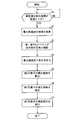
- FIG. 9 is a flowchart showing the brightness correction operation of the LED display device 100.
- the luminance correction operation is performed every luminance correction unit time (for example, 100 minutes).
- the luminance correction coefficient calculation unit 12 determines whether the luminance correction unit time has elapsed since the previous calculation of the luminance correction coefficient (step S1).
- the luminance correction coefficient calculation unit 12 refers to the cumulative lighting time storage unit 6 and searches for the maximum cumulative lighting time trmax, tgmax, tbmax for the LED elements of each color (step S2). ).
- the maximum cumulative lighting time trmax is the maximum cumulative lighting time among the cumulative lighting times of all the red LED elements provided in the display unit 10.
- the maximum cumulative lighting time tgmax is the maximum cumulative lighting time among the cumulative lighting times of all the green LED elements provided in the display unit 10.
- the maximum cumulative lighting time tbmax is the maximum cumulative lighting time among the cumulative lighting times of all blue LED elements provided in the display unit 10.
- the luminance correction coefficient calculation unit 12 refers to the luminance decrease rate storage unit 11 and determines whether each of the first and second aging display units 21 and 22 is normal or malfunctioning (step S3). .
- the luminance correction coefficient calculation unit 12 sets the maximum cumulative lighting times trmax, tgmax, and tbmax of the LED elements of the respective colors with respect to the luminance decrease rates kr (t), kg (t), and kg (t) of the first aging display unit 21. Corresponding luminance reduction rates kr (trmax), kg (tgmax), and kb (tbmax) are obtained.
- the first aging display unit 21 includes a measurement LED element that is not lit, so the first It determines with the aging display part 21 having failed.
- the luminance correction coefficient calculation unit 12 makes a failure determination for the second aging display unit 22. Details of the failure determination method will be described later.
- the luminance correction coefficient calculation unit 12 uses the luminance reduction rate and the temperature measurement result regarding the first aging display unit 21 to correct the luminance. The coefficient is calculated.
- the luminance reduction rate and the temperature measurement result regarding the normal aging display unit are used to determine the luminance.
- the correction coefficient is calculated.
- the luminance correction coefficient calculation unit 12 calculates the luminance correction coefficient using the luminance decrease rate and the temperature measurement result related to the first aging display unit 21 unless otherwise specified.
- the luminance correction coefficient calculation unit 12 obtains the maximum luminance reduction rate krgb (step S4).
- the luminance correction coefficient calculation unit 12 selects the largest luminance reduction rate among kr (trmax), kg (tgmax), and kb (tbmax) and sets it as the maximum luminance reduction rate krgb. That is, the maximum luminance reduction rate krgb is expressed by the following equation (2).
- the luminance correction coefficient calculation unit 12 calculates the luminance correction coefficients hr, hg, and gb for each LED element based on the maximum luminance decrease rate krgb (step S5).
- the brightness correction coefficient calculation unit 12 refers to the temperature storage unit 41 that stores the temperature of the display unit 10 and the temperature storage unit 42 that stores the temperatures of the first and second aging display units 21 and 22.
- the brightness correction of each LED element calculated in step S5 is performed using the temperature correction functions r ⁇ (t), g ⁇ (t), b ⁇ (t) shown in FIG.
- the temperature error of the coefficients hr, hg, hb is corrected.
- luminance correction coefficients hr2, hg2, and hb2 in which the temperature error is corrected are obtained (step S6).
- the luminance correction unit 4 performs luminance correction of each LED element based on the corrected luminance correction coefficient calculated by the luminance correction coefficient calculation unit 12 (step S7). That is, the luminance correction unit 4 controls the first driving unit 5 to correct the duty ratio of each LED element based on the corrected luminance correction coefficient.
- the luminance of the LED element can be corrected by correcting the duty ratio of the LED element based on the luminance correction coefficient.
- the current luminance of the LED elements of each color is Rp, Gp, Bp
- the luminance reduction rate of each color at each cumulative lighting time t is kr (t), kg (t), kb (t)
- the maximum luminance reduction rate is krgb.
- the current brightness Rp, Gp, Bp of the LED elements of each color in the formula (3) is expressed by the formula (4) when the initial brightness of the LED elements of each color is R0, G0, B0.
- Equation (5) luminance Rcomp, Gcomp, and Bcomp after luminance correction of the LED elements of the respective colors are expressed by equation (5).
- Expression (5) the luminance Rcomp, Gcomp, and Bcomp after the luminance correction of the LED elements of the respective colors are uniformly corrected with the maximum luminance reduction rate krgb with respect to the initial luminances R0, G0, and B0. It becomes.
- the luminance correction coefficient calculation unit 12 calculates the luminance correction coefficients hr, hg, and hb for all the LED elements of each color provided in the display unit 10.
- the luminance correction coefficient calculation unit 12 refers to the temperature storage units 41 and 42 and calculates temperature differences Tr, Tg, and Tb for all the LED elements of each color provided in the display unit 10. Then, the luminance correction coefficient calculation unit 12 corrects the error of the luminance reduction rate due to the temperature difference using the temperature correction functions g ⁇ (t), b ⁇ (t), and r ⁇ (t). Luminances Rcomp2, Gcomp2, and Bcomp2 obtained by further correcting the temperature errors of the luminances Rcomp, Gcomp, and Bcomp of the LED elements of the respective colors are expressed by Expression (6). That is, the luminance correction coefficients hr2, hg2, and hb2 in which the temperature error is corrected are expressed by Expression (7).
- the luminance correction is performed so that the luminance of each LED element provided in the display unit 13 is unified with the luminance of the LED element having the greatest luminance decrease.
- the luminance correction may be performed so as to maintain the initial luminance by increasing the luminance of each LED element.
- the initial luminances R0, G0, B0 of the LED elements of the respective colors are set to, for example, 50% of the maximum luminance.
- the luminance correction coefficient calculation unit 12 obtains the luminance reduction rate by referring to the cumulative lighting time storage unit 6 and the luminance reduction rate storage unit 11 for each LED element. Then, the luminance correction coefficient calculation unit 12 calculates the luminance correction coefficient so that the luminance of each LED element becomes the initial luminance.
- the current luminance of the LED elements of each color is Rp, Gp, Bp
- the luminance reduction rate of each color at each cumulative lighting time t is kr (t), kg (t), kb (t)
- the maximum luminance reduction rate is krgb.
- Equation (9) luminance after luminance correction of the LED elements of the respective colors is corrected to the initial value.
- the luminance correction coefficient calculation unit 12 refers to the temperature storage units 41 and 42 and calculates temperature differences Tr, Tg, and Tb for all the LED elements of each color provided in the display unit 10. Then, the luminance correction coefficient calculation unit 12 corrects the error of the luminance reduction rate due to the temperature difference using the temperature correction functions g ⁇ (t), b ⁇ (t), and r ⁇ (t).
- the luminances Rcomp2, Gcomp2, and Bcomp2 obtained by further correcting the temperature errors of the luminances Rcomp, Gcomp, and Bcomp of the LED elements of the respective colors are expressed by Expression (10). That is, the luminance correction coefficients hr2, hg2, and hb2 in which the temperature error is corrected are expressed by Expression (11).
- a failure determination method for the first and second aging display units 21 and 22 in step 3 of FIG. 9 will be described.
- the failure determination for the first aging display unit 21 will be described.
- the first aging display unit 21 is provided with only one measurement LED element, it is determined that a failure occurs when the measurement LED element is not lit.
- the first aging display unit 21 includes a plurality of measurement LED elements, it is necessary to assume a situation where one measurement LED element is not lit and other measurement LED elements are lit. .
- the threshold value of the luminance reduction rate used for the failure determination is set to a value (for example, 25%) or less that can determine the non-lighting of one measurement LED element.
- the threshold value may be set to (100 ⁇ ((N ⁇ 1) / N ⁇ 100)) or less.
- the output of the video signal processing unit 3 is corrected based on the luminance correction coefficient calculated for each LED element.
- the correction target is not limited to the output of the video signal processing unit 3. . It suffices if the duty ratio or drive current of the drive signal of each LED element is finally corrected based on the correction coefficient.
- the measurement LED elements provided in the first and second aging display units 21 and 22 are equivalent to the LED elements provided in the display unit 10.
- LED elements vary in luminance and wavelength depending on the production lot.
- the LED elements are classified by BIN code or the like according to luminance, wavelength or the like.
- the LED element provided in the display unit 10 and the measurement LED elements provided in the first and second aging display units 21 and 22 are the same in the same production lot and the same A BIN code is preferred.
- the temperature correction functions r ⁇ (t), g ⁇ (t), and b ⁇ (t) are determined in advance, and correction is performed when there is an influence on the luminance reduction rate due to the temperature difference. Temperature correction functions r ⁇ 1 (t), g ⁇ 1 (t), b ⁇ 1 (t) when the temperature difference is small, and temperature correction functions r ⁇ 2 (t), g ⁇ 2 (t), b ⁇ 2 (t) when the temperature difference is small By determining in advance, more accurate correction is possible.
- the small threshold values r ⁇ 1, g ⁇ 1, and b ⁇ 1 and the large threshold values r ⁇ 2, g ⁇ 2, and b ⁇ 2 are set and Tr ⁇ r ⁇ 1, Tg ⁇ g ⁇ 1, and Tb ⁇ b ⁇ 1, the influence of the temperature difference can be ignored.
- Tr ⁇ r ⁇ 2, g ⁇ 1 ⁇ Tg ⁇ g ⁇ 2, and b ⁇ 1 ⁇ Tb ⁇ b ⁇ 2 the luminance reduction rate is corrected using the temperature correction functions r ⁇ 1 (t), g ⁇ 1 (t), and b ⁇ 1 (t).
- the luminance reduction rate is corrected using the temperature correction functions r ⁇ 2 (t), g ⁇ 2 (t), b ⁇ 2 (t).
- the temperature correction functions r ⁇ 2 (t), g ⁇ 2 (t), b ⁇ 2 (t) As described above, by performing correction using a plurality of temperature correction functions according to the magnitude of the temperature difference, it is possible to correct the difference in luminance reduction rate due to the temperature difference with higher accuracy.
- the temperature difference is compared with the threshold value to determine whether or not the correction using the temperature correction function is performed.
- the display area may be divided into a plurality of areas in advance, and the determination may be performed for each area. That is, with respect to the representative LED elements in each region, it is determined whether or not the correction by the temperature correction function is performed by comparing the temperature difference and the threshold value, and the determination result is determined for all the LED elements arranged in the region. You may apply to.
- the division pattern of the display area of the display unit 10 is preferably determined with reference to the temperature gradient of the LED elements in the display area.
- the LED display device 100 is configured to include two aging display units (that is, the first and second aging display units 21 and 22). It is good also as a structure provided with one aging display part. By adopting a configuration including three or more aging display units, it is possible to further improve the reliability against failure of the aging display unit of the LED display device 100.
- the video signal processing unit 3, the luminance correction coefficient calculation unit 12, the luminance correction unit 4, the cumulative lighting time storage unit 6, and the first and second aging display units 21 and 22 are displayed on the display unit.
- the present invention can be applied to an existing display module. Note that these units can be provided in the display module.
- the LED display device 100 includes a display unit 10 including at least one display module including a plurality of LED elements and a plurality of display units 10 provided on the basis of a video signal received from the video signal processing unit 3.
- 1st drive part 5 which drives an LED element
- 1st temperature detection part 31 which detects the temperature of display part 10
- the 1st aging display part provided with at least 1 LED element for measurement equivalent to an LED element 21
- the second aging display unit 22 including at least one measurement LED element equivalent to the LED element, and the measurement LED elements provided in the first aging display unit 21 and the second aging display unit 22 are driven.
- a luminance correction coefficient calculation unit 12 that calculates a luminance correction coefficient, and controls the first drive unit 5 to correct the luminance of each of the plurality of LED elements based on the luminance correction coefficient.
- the LED display device 100 includes an aging display unit (first and second aging display units 21 and 22) separately from the display unit 10 that displays an image and the like. And the brightness
- the luminance correction coefficient is further corrected in consideration of the difference in luminance reduction rate due to the temperature difference between the display unit 10 and the aging display unit. Accordingly, it is possible to perform highly accurate luminance correction for each of the plurality of LED elements included in the display unit 10, so that the luminance uniformity and color uniformity of the display unit 10 can be maintained in a long-term operation. .
- the first and second aging display units 21 and 22 are arranged. Thereby, even if one of the aging display units breaks down, the luminance correction of the display unit 10 can be performed correctly by using the accurate luminance reduction rate and temperature obtained from the other aging display unit. Therefore, the luminance of the display unit 10 can be kept stable and uniform during long-term operation.
- the luminance correction coefficient calculation unit 12 refers to the luminance decrease rate storage unit 11, so that the first aging display unit 21 and the second aging display unit 22 When a failure is detected for each, the luminance correction coefficient calculation unit 12 refers to the information on the normal aging display unit with respect to the luminance decrease rate storage unit 11 and the second temperature detection unit 32 when the failure is detected. Find the rate.
- the luminance correction of the display unit 10 can be performed correctly by using the accurate luminance reduction rate obtained from the other aging display unit. Therefore, the luminance of the display unit 10 can be kept stable and uniform during long-term operation.
- the luminance correction coefficient calculation unit 12 refers to the temperature detected by the first temperature detection unit 31 and the temperature detected by the second temperature detection unit 32, The luminance correction coefficient is corrected based on predetermined temperature correction functions r ⁇ (t), g ⁇ (t), b ⁇ (t). Therefore, by determining the temperature correction function in advance, it is possible to accurately correct the difference in the luminance reduction rate due to the temperature difference using the temperature correction function.
- the temperature correction functions r ⁇ (t), g ⁇ (t), and b ⁇ (t) are set in advance so that the temperature difference between two LED elements equivalent to the LED elements is predetermined. It is a function showing the difference of the brightness
- the temperature correction function is used. Do not make corrections. Thereby, it is possible to reduce the calculation process of the luminance correction coefficient calculation unit 12.
- the luminance correction coefficient calculation unit 12 uses the luminance of the LED element having the largest luminance reduction rate among the plurality of LED elements as a reference. A correction coefficient is calculated.
- the luminance of each LED element provided in the display unit 13 is unified to the luminance of the LED element having the greatest luminance reduction. Since balance can be maintained, variation in luminance is improved.
- the luminance correction method that unifies the luminance of the LED element having the greatest luminance reduction has an advantage that the initial luminance can be increased.
- the first and second aging display units 21 and 22 are arranged for luminance measurement separately from the display unit 10. Accordingly, it is possible to always detect a change with time of the LED element without blocking the display of the display unit 10 by the luminance sensor.
- the luminance correction coefficient calculation unit 12 calculates the luminance correction coefficient so that each of the plurality of LED elements provided in the display unit 10 maintains a predetermined luminance. May be.
- the luminance during operation can be kept constant although the initial luminance is lowered. Therefore, in the long-term operation of the LED display device 100, it is possible to prevent the brightness of the display image on the display unit 10 from gradually decreasing.
- FIG. 12 is a diagram showing a luminance reduction rate when green LED elements are driven at different duty ratios. As shown in FIG. 12, the luminance reduction rate increases as the duty ratio increases.
- each of the first and second aging display units 21 and 22 includes a plurality of measurement LED elements, and each LED element is driven with a different duty ratio.
- each of the plurality of measurement LED elements is driven with a duty ratio of 100%, 75%, 50%, and 25%.
- the luminance correction coefficient calculation unit 12 refers to the luminance decrease rate storage unit 11 and searches for the duty ratio having the cumulative lighting time closest to the maximum cumulative lighting time (that is, 50K) among the plurality of duty ratios. In FIG. 12, a duty ratio of 50% corresponds. Accordingly, the luminance correction coefficient calculation unit 12 refers to the luminance reduction rate with the duty ratio of 50% to obtain the luminance reduction rate (kg (tgmax)).
- the measurement LED element driving method and the method of obtaining the luminance reduction rates kr (trmax), kg (tgmax), and kb (tbmax) are the same as those in the first embodiment, the description thereof is omitted.
- At least one of the first aging display unit 21 and the second aging display unit 22 includes a plurality of measurement LED elements
- the second driving unit 8 includes a plurality of Each of the measurement LED elements is driven with a different duty ratio
- the luminance decrease rate storage unit 11 is configured to measure the accumulated LED lighting time of the plurality of measurement LED elements and the measurement LED element based on the measurement result of the luminance measurement unit 9.
- the relationship with the luminance reduction rate is stored for each duty ratio, and the luminance correction coefficient calculation unit 12 refers to the luminance reduction rate of the cumulative lighting time of the LED element for measurement closest to the cumulative lighting time of the LED element,
- luminance fall rate of an LED element is calculated
- the luminance correction coefficient calculation unit 12 By driving each of the plurality of measurement LED elements at different duty ratios, the luminance correction coefficient calculation unit 12 refers to the luminance reduction rate of the measurement LED elements driven at a duty ratio closer to the drive conditions of the LED elements. It becomes possible to do. Therefore, the luminance correction coefficient calculation unit 12 can obtain the luminance reduction rate with higher accuracy.
- FIG. 13 is a detailed block diagram around the display unit 10 of the LED display device 100 according to the third embodiment.
- the display unit 10 includes one display module.
- the display unit 10 includes a plurality of display modules. A plurality of display modules are combined to form one screen.
- the first drive unit 5 selects an area corresponding to each display module from the video signal input from the luminance correction unit 4, and drives each display module.
- the plurality of display modules are connected in a daisy chain, for example.
- the first temperature detection unit 31 individually detects the temperatures of the plurality of LED elements included in each display module.
- the display unit 10 includes one display module.
- the display module includes 16 red, green, and blue LED elements, for a total of 48 LED elements. It was set as the structure provided with.
- the luminance correction coefficient calculation unit 12 calculates a luminance correction coefficient for each of the 48 LED elements.
- the display unit 10 includes four display modules as shown in FIG. Since each display module includes 48 LED elements, the display unit 10 includes 192 LED elements in total. In this case, the luminance correction coefficient calculation unit 12 calculates a luminance correction coefficient for each of the 192 LED elements.
- the calculation method of the luminance correction coefficient in the third embodiment is the same as that in the first embodiment. As a result of correcting the brightness of each LED element by the brightness correction coefficient, the brightness of all the LED elements provided in the plurality of display modules becomes equal to each other.
- the luminance correction coefficient calculation unit 12 calculates luminance correction coefficients for all LED elements provided in the display unit 10.
- the configuration other than the number of display modules provided in the display unit 10 is the same as that in the first embodiment, the description thereof is omitted.
- the display unit 10 includes a plurality of display modules, and a plurality of display modules are combined to form one screen, and the first temperature detection unit 31 includes a plurality of displays. The temperature of each module is detected, and the luminance correction coefficient calculation unit 12 calculates the luminance correction coefficient so that the luminances of all the LED elements included in the plurality of display modules are equal to each other.
- the display unit 10 includes a plurality of display modules and a large screen is configured by combining the plurality of display modules, luminance correction with extremely high accuracy can be performed as in the first embodiment. Therefore, it is possible to maintain the luminance uniformity and color uniformity of a large screen in a long-term operation.
- the entire display unit 10 can be used even when some display modules are replaced in the display unit 10. It is possible to perform luminance correction. Accordingly, even when the display module is replaced in a long-term operation, it is possible to maintain the luminance uniformity and color uniformity of the large screen.
Abstract
The purpose of the present invention is to provide an LED display device and a method for correcting the luminance of the LED display capable of correcting the luminance of each LED element to thereby suppress the degradation of image quality due to the variation in the characteristics of each LED element. An LED display device (100) comprises: a display unit (10) including a display module composed of a plurality of LED elements; a first temperature detector (31); a first and a second aging display unit (21, 22) equipped with at least one measurement LED element that is equivalent to the LED element; a luminance measurement unit (9) for measuring the luminance of the measurement LED element; a second temperature detector (32); a cumulative lighting time storage unit (6) for storing the cumulative lighting time of the plurality of LED elements; a luminance reduction rate storage unit (11) for storing the relationship between the cumulative lighting time of the measurement LED element and the luminance reduction rate of the measurement LED element; and a luminance correction factor calculation unit (12) for calculating the luminance correction factors for the plurality of LED elements. The luminance correction factor calculation unit (12) corrects luminance correction factors on the basis of the temperatures detected by the first and the second temperature detectors (31, 32).
Description
本発明はLED装置およびその輝度補正方法に関し、特にマトリクス状に配置された複数のLED(Light Emitting Diode:発光ダイオード)を点滅制御することにより映像情報を表示するLED表示装置およびその輝度補正方法に関する。
The present invention relates to an LED device and a luminance correction method thereof, and more particularly to an LED display device that displays video information by controlling blinking of a plurality of LEDs (Light Emitting Diodes) arranged in a matrix and a luminance correction method thereof. .
LEDを用いて構成される表示装置は、LEDの技術発展と低コスト化により屋外、屋内の広告表示等に多く使用されている。これらのLED表示装置はこれまで自然画およびアニメーションの動画像表示が主であった。近年は、画素ピッチの狭ピッチ化に伴い視認距離が短くなることで、会議室、監視用途などに使用されている。特に監視用途においては静止画に近いパソコン画像を表示することが多くなっている。しかし、LEDは点灯時間が長くなるにしたがって輝度が低下するため、画像の内容により各LEDの輝度低下率が異なり結果的に画素毎に輝度ばらつき及び色ばらつきが発生する。
Display devices that use LEDs are often used for outdoor and indoor advertising display, etc., due to the technological development and cost reduction of LEDs. These LED display devices have so far mainly displayed moving images of natural images and animations. In recent years, the viewing distance has become shorter as the pixel pitch becomes narrower, so it has been used for conference rooms, monitoring applications, and the like. Especially in surveillance applications, personal computer images close to still images are often displayed. However, since the luminance of the LED decreases as the lighting time becomes longer, the luminance decrease rate of each LED differs depending on the content of the image, resulting in luminance variation and color variation for each pixel.
上述した輝度ばらつきおよび色ばらつきを低減するために、LEDの表示部の輝度を検出し、輝度データを補正する方法が知られている。また、LEDの点灯時間を積算し、積算時間に応じてすでに測定された輝度補正係数をもとに輝度を補正する方法が知られている(例えば、特許文献1、2参照)。
In order to reduce the above-described luminance variation and color variation, a method of detecting luminance of an LED display unit and correcting luminance data is known. Also, a method is known in which the LED lighting time is integrated and the luminance is corrected based on the luminance correction coefficient that has already been measured according to the integrated time (see, for example, Patent Documents 1 and 2).
LEDの点灯時間の違いによって生じる輝度、色ばらつきについては、寿命試験などによりLEDの輝度低下率をある程度予測することが可能である。しかしながら、LEDの製造ロットの違いによる特性の違いを予測することは難しい。また、実際のLEDディスプレイの輝度を検出することにより補正の精度を向上させることができるが、輝度測定のための画像を表示させる必要があり、24時間稼働のシステムにおいては運用を停止させる必要が生じてしまう。
For brightness and color variations caused by differences in LED lighting time, it is possible to predict the LED brightness reduction rate to some extent by a life test or the like. However, it is difficult to predict differences in characteristics due to differences in LED production lots. Although the accuracy of correction can be improved by detecting the brightness of the actual LED display, it is necessary to display an image for brightness measurement, and it is necessary to stop the operation in a 24-hour system. It will occur.
運用を停止している時間はできる限り短いことが望まれるが、運用を停止する時間を短くすると、結果的に補正の精度が向上せず輝度ばらつき、色ばらつきが残存し、LED表示部の画質が低下する問題があった。また、画質の低下を解決するために新しいLEDモジュールに交換する必要が生じるという問題があった。
It is desirable that the operation stop time is as short as possible. However, if the operation stop time is shortened, the correction accuracy does not improve, resulting in luminance variations and color variations, and the image quality of the LED display section. There was a problem that decreased. In addition, there is a problem that it is necessary to replace the LED module with a new one in order to solve the deterioration in image quality.
本発明は以上のような課題を解決するためになされたものであり、各LED素子の特性のばらつきによる画質の低下を抑制するように各LED素子の輝度の補正を行うLED表示装置およびその輝度補正方法の提供を目的とする。
The present invention has been made to solve the above-described problems, and an LED display device that corrects the luminance of each LED element so as to suppress deterioration in image quality due to variations in the characteristics of the LED elements, and the luminance thereof. The purpose is to provide a correction method.
本発明に係るLED表示装置は、複数のLED素子を備える表示モジュールを、少なくとも1つ備える表示部と、映像信号処理部から受ける映像信号に基づいて前記表示部に備わる前記複数のLED素子を駆動する第1の駆動部と、表示部の温度を検出する第1の温度検出部と、LED素子と同等の測定用LED素子を少なくとも1つ備える第1のエージング表示部と、LED素子と同等の測定用LED素子を少なくとも1つ備える第2のエージング表示部と、第1のエージング表示部および第2のエージング表示部に備わる測定用LED素子を駆動する第2の駆動部と、第1のエージング表示部および第2のエージング表示部に備わる前記測定用LED素子の輝度を測定する輝度測定部と、第1のエージング表示部および第2のエージング表示部のそれぞれの温度を検出する第2の温度検出部と、表示部に備わる複数のLED素子のそれぞれに関して、累積点灯時間を記憶する累積点灯時間記憶部と、第1のエージング表示部および第2のエージング表示部に備わる測定用LED素子の累積点灯時間と、輝度測定部の測定結果に基づく測定用LED素子の輝度低下率との関係を記憶する輝度低下率記憶部と、表示部に備わる複数のLED素子のそれぞれに関して、累積点灯時間記憶部および輝度低下率記憶部を参照して、輝度補正係数を算出する輝度補正係数算出部と、輝度補正係数に基づいて前記複数のLED素子それぞれの輝度を補正するように第1の駆動部を制御する輝度補正部と、を備え、輝度補正係数算出部は、第1の温度検出部が検出した温度および第2の温度検出部が検出した温度に基づいて、表示部に備わる複数のLED素子のそれぞれの輝度補正係数を補正する。
An LED display device according to the present invention drives a plurality of LED elements included in the display unit based on a display unit including at least one display module including a plurality of LED elements and a video signal received from the video signal processing unit. A first drive unit, a first temperature detection unit that detects the temperature of the display unit, a first aging display unit that includes at least one measurement LED element equivalent to the LED element, and an LED element equivalent A second aging display unit comprising at least one measurement LED element, a second drive unit for driving the measurement LED elements provided in the first aging display unit and the second aging display unit, and a first aging A luminance measuring unit for measuring the luminance of the LED element for measurement provided in the display unit and the second aging display unit, the first aging display unit and the second aging A second temperature detection unit that detects each temperature of the display unit; a cumulative lighting time storage unit that stores a cumulative lighting time for each of the plurality of LED elements included in the display unit; a first aging display unit; A luminance reduction rate storage unit that stores a relationship between a cumulative lighting time of the measurement LED element provided in the aging display unit 2 and a luminance reduction rate of the measurement LED element based on a measurement result of the luminance measurement unit; and a display unit. With respect to each of the plurality of LED elements, with reference to the cumulative lighting time storage unit and the luminance decrease rate storage unit, a luminance correction coefficient calculation unit that calculates a luminance correction coefficient, and each of the plurality of LED elements based on the luminance correction coefficient A luminance correction unit that controls the first drive unit to correct the luminance, and the luminance correction coefficient calculation unit includes the temperature detected by the first temperature detection unit and the second temperature detection unit. Parts is based on the detected temperature, correcting the respective luminance correction coefficient of the plurality of LED elements included in the display unit.
本発明に係る輝度補正方法は、LED表示装置の輝度補正方法であって、LED表示装置は、複数のLED素子を備える表示モジュールを、少なくとも1つ備える表示部と、映像信号処理部から受ける映像信号に基づいて表示部に備わる複数のLED素子を駆動する第1の駆動部と、第1の温度検出部と、LED素子と同等の測定用LED素子を少なくとも1つ備える第1のエージング表示部と、LED素子と同等の測定用LED素子を少なくとも1つ備える第2のエージング表示部と、第1のエージング表示部および第2のエージング表示部に備わる測定用LED素子を駆動する第2の駆動部と、輝度測定部と、第2の温度検出部と、累積点灯時間記憶部と、輝度低下率記憶部と、輝度補正係数算出部と、輝度補正部と、を備え、輝度補正方法は、(a)第1の温度検出部が、表示部の温度を検出する工程と、(b)輝度測定部が、第1のエージング表示部および第2のエージング表示部に備わる測定用LED素子の輝度を測定する工程と、(c)第2の温度検出部が、第1のエージング表示部および第2のエージング表示部のそれぞれの温度を検出する工程と、(d)累積点灯時間記憶部が、表示部に備わる複数のLED素子のそれぞれに関して、累積点灯時間を記憶する工程と、(e)輝度低下率記憶部が、第1のエージング表示部および第2のエージング表示部に備わる測定用LED素子の累積点灯時間と、輝度測定部の測定結果に基づく測定用LED素子の輝度低下率との関係を記憶する工程と、(f)輝度補正係数算出部が、表示部に備わる複数のLED素子のそれぞれに関して、累積点灯時間記憶部および輝度低下率記憶部(を参照して、輝度補正係数を算出する工程と、(g)輝度補正部が、輝度補正係数に基づいて複数のLED素子それぞれの輝度を補正するように第1の駆動部を制御する工程と、(h)輝度補正係数算出部が、第1の温度検出部が検出した温度および第2の温度検出部が検出した温度に基づいて、表示部に備わる複数のLED素子のそれぞれの輝度補正係数を補正する工程と、を備える。
A brightness correction method according to the present invention is a brightness correction method for an LED display device, and the LED display device includes a display unit including at least one display module including a plurality of LED elements, and an image received from a video signal processing unit. A first aging display unit including at least one measurement LED element equivalent to a first drive unit that drives a plurality of LED elements provided in the display unit based on a signal, a first temperature detection unit, and the LED element A second aging display unit including at least one measurement LED element equivalent to the LED element, and a second drive for driving the measurement LED element provided in the first aging display unit and the second aging display unit A luminance correction unit, a luminance measurement unit, a second temperature detection unit, a cumulative lighting time storage unit, a luminance reduction rate storage unit, a luminance correction coefficient calculation unit, and a luminance correction unit. The method includes (a) a step in which the first temperature detection unit detects the temperature of the display unit, and (b) a measurement LED provided in the first aging display unit and the second aging display unit by the luminance measurement unit. A step of measuring the luminance of the element; (c) a step in which the second temperature detection unit detects the respective temperatures of the first aging display unit and the second aging display unit; and (d) storage of accumulated lighting time. A step in which the unit stores the cumulative lighting time for each of the plurality of LED elements provided in the display unit, and (e) a measurement in which the luminance reduction rate storage unit is provided in the first aging display unit and the second aging display unit. Storing the relationship between the cumulative lighting time of the LED element for measurement and the luminance reduction rate of the LED element for measurement based on the measurement result of the luminance measurement unit, and (f) a plurality of luminance correction coefficient calculation units provided in the display unit LED element With respect to this, the step of calculating the luminance correction coefficient with reference to the cumulative lighting time storage unit and the luminance decrease rate storage unit (g), and (g) the luminance correction unit determines the luminance of each of the plurality of LED elements based on the luminance correction coefficient. And (h) the luminance correction coefficient calculation unit is controlled based on the temperature detected by the first temperature detection unit and the temperature detected by the second temperature detection unit. And a step of correcting the luminance correction coefficient of each of the plurality of LED elements provided in the display unit.
本発明に係るLED表示装置およびその輝度補正方法によれば、表示部と、第1、第2のエージング表示部との温度差による輝度低下率の差異を考慮して、輝度補正係数が補正される。従って、表示部に備わる複数のLED素子のそれぞれに関して、極めて精度の高い輝度補正が可能となる。従って、長期の運用において表示部の輝度の均一性および色均一性を維持することが可能となる。さらに、本発明に係るLED表示装置およびその輝度補正方法においては、第1、第2のエージング表示部が配置される。これにより、どちらかのエージング表示部が故障しても、もう一方のエージング表示部から得られる正確な輝度低下率および温度を利用することによって、表示部の輝度補正を正しく行うことができる。従って、長期運用において表示部の輝度を安定して均一に保つことができる。
According to the LED display device and the luminance correction method thereof according to the present invention, the luminance correction coefficient is corrected in consideration of the difference in luminance reduction rate due to the temperature difference between the display unit and the first and second aging display units. The Therefore, it is possible to perform highly accurate luminance correction for each of the plurality of LED elements provided in the display unit. Therefore, it is possible to maintain the luminance uniformity and color uniformity of the display unit in a long-term operation. Furthermore, in the LED display device and the luminance correction method thereof according to the present invention, first and second aging display units are arranged. Thus, even if one of the aging display units breaks down, the luminance correction of the display unit can be performed correctly by using the accurate luminance reduction rate and temperature obtained from the other aging display unit. Therefore, the luminance of the display unit can be kept stable and uniform during long-term operation.
この発明の目的、特徴、局面、および利点は、以下の詳細な説明と添付図面とによってより明白となる。
The objects, features, aspects and advantages of the present invention will become more apparent from the following detailed description and the accompanying drawings.
<実施の形態1>
<構成>
図1は、本実施の形態1におけるLED表示装置100の機能ブロック図である。また、図2は、表示部10周辺のより詳しいブロック図である。図3は、第1、第2のエージング表示部21,22周辺のより詳しいブロック図である。 <Embodiment 1>
<Configuration>
FIG. 1 is a functional block diagram of theLED display device 100 according to the first embodiment. FIG. 2 is a more detailed block diagram around the display unit 10. FIG. 3 is a more detailed block diagram around the first and second aging display units 21 and 22.
<構成>
図1は、本実施の形態1におけるLED表示装置100の機能ブロック図である。また、図2は、表示部10周辺のより詳しいブロック図である。図3は、第1、第2のエージング表示部21,22周辺のより詳しいブロック図である。 <Embodiment 1>
<Configuration>
FIG. 1 is a functional block diagram of the
図1に示すように、LED表示装置100は、表示部10、第1の駆動部5、第1の温度検出部31、第1、第2のエージング表示部21,22、第2の駆動部8、輝度測定部9、第2の温度検出部32、輝度低下率記憶部11、累積点灯時間記憶部6、輝度補正係数算出部12および輝度補正部4を備える。
As shown in FIG. 1, the LED display device 100 includes a display unit 10, a first drive unit 5, a first temperature detection unit 31, first and second aging display units 21 and 22, and a second drive unit. 8, a luminance measurement unit 9, a second temperature detection unit 32, a luminance decrease rate storage unit 11, a cumulative lighting time storage unit 6, a luminance correction coefficient calculation unit 12, and a luminance correction unit 4.
表示部10に備わる表示モジュールは、M行N列のマトリクス状に配置された複数の単位画素を備える。M行N列とは、例えば図2に示すように4行4列であるがこれに限定されない。各単位画素には、赤(R)、緑(G)、青(B)の3個のLED素子が配置されている。第1の温度検出部31は、表示部10に備わる各LED素子の温度を個別に検出する。第1の温度検出部31が検出した温度は温度記憶部41に記憶される。
The display module provided in the display unit 10 includes a plurality of unit pixels arranged in a matrix of M rows and N columns. The M rows and N columns are, for example, 4 rows and 4 columns as shown in FIG. 2, but are not limited thereto. In each unit pixel, three LED elements of red (R), green (G), and blue (B) are arranged. The first temperature detection unit 31 individually detects the temperature of each LED element provided in the display unit 10. The temperature detected by the first temperature detection unit 31 is stored in the temperature storage unit 41.
なお、本実施の形態1では、表示部10が表示モジュールを1個備える構成としているが、大画面を構成するために表示モジュールを複数備える構成としてもよい。表示モジュールを複数備える構成は実施の形態3で説明する。
In the first embodiment, the display unit 10 includes one display module. However, the display unit 10 may include a plurality of display modules in order to configure a large screen. A configuration including a plurality of display modules will be described in Embodiment 3.
第1の駆動部5は、映像信号処理部3から受信した映像信号に基づいて表示部10に備わる複数のLED素子を駆動する。映像信号処理部3の入力端子2にはLED表示装置100の外部から映像信号が入力される。映像信号処理部3は、外部から入力された映像信号に対して、表示に必要な領域を選択する処理、ガンマ補正処理などを行う。
The first driving unit 5 drives a plurality of LED elements provided in the display unit 10 based on the video signal received from the video signal processing unit 3. A video signal is input to the input terminal 2 of the video signal processing unit 3 from the outside of the LED display device 100. The video signal processing unit 3 performs processing for selecting a region necessary for display, gamma correction processing, and the like on a video signal input from the outside.
累積点灯時間記憶部6に格納されるデータは、表示部10に備わる各LED素子が点灯した時間の累積であって、一定の単位時間ごとに累積される。例えば、単位時間が1時間でデューティ比10%の輝度の点灯であれば、1時間ごとに0.1時間の点灯時間が、累積点灯時間記憶部6に格納されることになる。ここで、デューティ比は、単位時間ごとに取得したものを用いてもよい。また、単位時間における平均のデューティ比であってもよい。デューティ比による電流制御方法については後述する。
The data stored in the cumulative lighting time storage unit 6 is the cumulative time that each LED element included in the display unit 10 is lit, and is accumulated every certain unit time. For example, if the unit time is one hour and the luminance is 10%, the lighting time of 0.1 hour is stored in the cumulative lighting time storage unit 6 every hour. Here, what was acquired for every unit time may be used for a duty ratio. Moreover, the average duty ratio in unit time may be sufficient. A current control method based on the duty ratio will be described later.
第1、第2のエージング表示部21,22のそれぞれは、例えば図3に示すように2行2列に配置された4個の単位画素を備える。各単位画素には、赤、緑、青の測定用LED素子が1つずつ配置されている。なお、第1、第2のエージング表示部21,22のそれぞれは、少なくとも1個の単位画素を備えればよいが、単位画素を複数備える構成とすることにより、測定用LED素子において測定される輝度、温度の測定値が増える。従って、測定値の平均をとることにより、測定値のばらつきを抑えることが可能になる。
Each of the first and second aging display units 21 and 22 includes, for example, four unit pixels arranged in two rows and two columns as shown in FIG. Each unit pixel is provided with one LED element for measurement of red, green, and blue. Each of the first and second aging display units 21 and 22 may be provided with at least one unit pixel, but the measurement LED element is measured by providing a plurality of unit pixels. Increased brightness and temperature measurements. Therefore, by taking the average of the measured values, it is possible to suppress the variation in the measured values.
また、各色の測定用LED素子は、表示部10に設けられている各色LED素子と同等のLED素子であるとする。ここで、同等のLED素子とは、同じ仕様で製造されたLED素子を意味する。なお、表示部10に備わるLED素子と、第1、第2のエージング表示部21,22のそれぞれに備わる測定用LED素子とは、同じ製造ロットであるのが望ましい。
Further, it is assumed that the LED elements for measurement of each color are LED elements equivalent to the LED elements of each color provided in the display unit 10. Here, an equivalent LED element means an LED element manufactured with the same specifications. The LED elements provided in the display unit 10 and the measurement LED elements provided in each of the first and second aging display units 21 and 22 are preferably in the same production lot.
第2の温度検出部32は、第1のエージング表示部21用の温度検出部321と、第2のエージング表示部22用の温度検出部322とを備える。温度検出部321は、第1のエージング表示部21に備わる各測定用LED素子の温度を個別に検出する。また、温度検出部322は、第2のエージング表示部22に備わる各測定用LED素子の温度を個別に検出する。第2の温度検出部32が検出した温度は温度記憶部42に記憶される。
The second temperature detection unit 32 includes a temperature detection unit 321 for the first aging display unit 21 and a temperature detection unit 322 for the second aging display unit 22. The temperature detection unit 321 individually detects the temperature of each measurement LED element provided in the first aging display unit 21. The temperature detection unit 322 individually detects the temperature of each measurement LED element provided in the second aging display unit 22. The temperature detected by the second temperature detection unit 32 is stored in the temperature storage unit 42.
輝度測定部9は、第1のエージング表示部21用の輝度測定部91と、第2のエージング表示部22用の輝度測定部92とを備える。輝度測定部91は、第1のエージング表示部21に備わる測定用LED素子の輝度を測定する。輝度測定部92は、第2のエージング表示部22に備わる測定用LED素子の輝度を測定する。第2の駆動部8は、第1、第2のエージング表示部21,22のそれぞれに備わる測定用LED素子を駆動する。
The luminance measuring unit 9 includes a luminance measuring unit 91 for the first aging display unit 21 and a luminance measuring unit 92 for the second aging display unit 22. The luminance measuring unit 91 measures the luminance of the measurement LED element provided in the first aging display unit 21. The luminance measuring unit 92 measures the luminance of the measurement LED element provided in the second aging display unit 22. The 2nd drive part 8 drives the LED element for a measurement with which each of the 1st, 2nd aging display parts 21 and 22 is equipped.
輝度低下率記憶部11は、測定用LED素子の累積点灯時間と、輝度測定部9の測定結果に基づく測定用LED素子の輝度低下率との関係を記憶する。なお、輝度低下率記憶部11は、第1、第2のエージング表示部21,22の両方に対して上記関係を記憶する。
The luminance reduction rate storage unit 11 stores the relationship between the cumulative lighting time of the measurement LED element and the luminance reduction rate of the measurement LED element based on the measurement result of the luminance measurement unit 9. The luminance decrease rate storage unit 11 stores the above relationship for both the first and second aging display units 21 and 22.
輝度補正係数算出部12は、表示部10に備わるLED素子のそれぞれに関して、累積点灯時間記憶部6および輝度低下率記憶部11を参照して、輝度補正係数を算出する。輝度補正係数の算出方法については後述する。
The luminance correction coefficient calculation unit 12 calculates a luminance correction coefficient for each of the LED elements included in the display unit 10 with reference to the cumulative lighting time storage unit 6 and the luminance decrease rate storage unit 11. A method for calculating the luminance correction coefficient will be described later.
輝度補正係数算出部12はさらに、第1の温度検出部31が検出した温度および第2の温度検出部32が検出した温度に基づいて、表示部10に備わるLED素子のそれぞれに関して、輝度補正係数を補正する。補正方法については後述する。輝度補正部4は、輝度補正係数算出部12が算出した輝度補正係数に従って映像信号処理回路部3の出力を補正する。
The luminance correction coefficient calculation unit 12 further includes a luminance correction coefficient for each of the LED elements included in the display unit 10 based on the temperature detected by the first temperature detection unit 31 and the temperature detected by the second temperature detection unit 32. Correct. The correction method will be described later. The luminance correction unit 4 corrects the output of the video signal processing circuit unit 3 in accordance with the luminance correction coefficient calculated by the luminance correction coefficient calculation unit 12.
なお、後述するように、輝度補正係数算出部12は、第1、第2のエージング表示部21,22が正常か故障しているかの判定を行い、正常なエージング表示部の輝度低下率および温度を参照して、輝度補正係数を算出する。第1、第2のエージング表示部21,22の両方とも正常な場合は、輝度補正係数算出部12は、例えば第1のエージング表示部21の輝度低下率および温度を参照して輝度補正係数を算出する。なお、第1、第2のエージング表示部21,22の両方とも正常な場合に、輝度補正係数算出部12は第1、第2のエージング表示部21,22のそれぞれを参照して、2通りの輝度補正係数を算出してもよい。この場合、輝度補正部4が行う輝度補正には、どちらか一方の輝度補正係数が用いられる。
As will be described later, the luminance correction coefficient calculation unit 12 determines whether the first and second aging display units 21 and 22 are normal or faulty, and the luminance reduction rate and temperature of the normal aging display unit. The luminance correction coefficient is calculated with reference to FIG. When both the first and second aging display units 21 and 22 are normal, the luminance correction coefficient calculation unit 12 refers to, for example, the luminance reduction rate and temperature of the first aging display unit 21 and calculates the luminance correction coefficient. calculate. When both the first and second aging display units 21 and 22 are normal, the luminance correction coefficient calculation unit 12 refers to each of the first and second aging display units 21 and 22 and performs two types. The luminance correction coefficient may be calculated. In this case, one of the luminance correction coefficients is used for the luminance correction performed by the luminance correction unit 4.
なお、本明細書において、以降では第1表示部10に備わるLED素子を単にLED素子と記載する。
In the present specification, the LED elements provided in the first display unit 10 are hereinafter simply referred to as LED elements.
図4は、LED表示装置100のハードウェア構成図である。図4に示すように、LED表示装置100は、入力インターフェースHW1、処理回路HW2、メモリHW3、記憶装置HW4、第1の駆動回路HW5、表示装置HW6、第1の温度検出装置HW7、第2の駆動回路HW8、第1のエージング表示装置HW9、第2のエージング表示装置HW10、輝度測定装置HW11および第1の温度検出装置HW12を備える。また、上記各構成要素はバスで相互に接続されている。
FIG. 4 is a hardware configuration diagram of the LED display device 100. As shown in FIG. 4, the LED display device 100 includes an input interface HW1, a processing circuit HW2, a memory HW3, a storage device HW4, a first drive circuit HW5, a display device HW6, a first temperature detection device HW7, a second A drive circuit HW8, a first aging display device HW9, a second aging display device HW10, a luminance measurement device HW11, and a first temperature detection device HW12 are provided. Each of the above components is connected to each other by a bus.
映像信号処理部3、輝度補正係数算出部12、輝度補正部4は処理回路HW2により実現される。処理回路HW2は、専用のハードウェアであってもよい。また、処理回路HW2はメモリHW3に格納されるプログラムを実行するCPU(Central Processing Unit、中央処理装置、処理装置、演算装置、マイクロプロセッサ、マイクロコンピュータ、プロセッサ、DSPともいう)であってもよい。
The video signal processing unit 3, the luminance correction coefficient calculation unit 12, and the luminance correction unit 4 are realized by the processing circuit HW2. The processing circuit HW2 may be dedicated hardware. Further, the processing circuit HW2 may be a CPU (Central Processing Unit, central processing unit, processing unit, arithmetic unit, microprocessor, microcomputer, processor, DSP) that executes a program stored in the memory HW3.
処理回路HW2が専用のハードウェアである場合、処理回路HW2は、例えば、単一回路、複合回路、プログラム化したプロセッサ、並列プログラム化したプロセッサ、ASIC、FPGA、またはこれらを組み合わせたものが該当する。映像信号処理部3、輝度補正係数算出部12、輝度補正部4の各部の機能それぞれを個別に設けた処理回路HW2で実現してもよいし、各部の機能をまとめて1つの処理回路HW2で実現してもよい。
When the processing circuit HW2 is dedicated hardware, the processing circuit HW2 corresponds to, for example, a single circuit, a composite circuit, a programmed processor, a parallel programmed processor, an ASIC, an FPGA, or a combination thereof. . The functions of each unit of the video signal processing unit 3, the luminance correction coefficient calculation unit 12, and the luminance correction unit 4 may be realized by the processing circuit HW2 provided individually, or the functions of the respective units may be integrated into one processing circuit HW2. It may be realized.
処理回路HW2がCPUの場合、映像信号処理部3、輝度補正係数算出部12、輝度補正部4の各機能は、ソフトウェア、ファームウェア、またはソフトウェアとファームウェアとの組み合わせにより実現される。ソフトウェアやファームウェアはプログラムとして記述され、メモリHW3に格納される。処理回路HW2は、メモリHW3に記憶されたプログラムを読み出して実行することにより、各部の機能を実現する。また、これらのプログラムは、映像信号処理部3、輝度補正係数算出部12、輝度補正部4の手順や方法をコンピュータに実行させるものであるともいえる。ここで、メモリHW3とは、例えば、RAM、ROM、フラッシュメモリー、EPROM、EEPROM等の、不揮発性または揮発性の半導体メモリや、磁気ディスク、フレキシブルディスク、光ディスク、コンパクトディスク、ミニディスク、DVD等が該当する。
When the processing circuit HW2 is a CPU, the functions of the video signal processing unit 3, the luminance correction coefficient calculation unit 12, and the luminance correction unit 4 are realized by software, firmware, or a combination of software and firmware. Software and firmware are described as programs and stored in the memory HW3. The processing circuit HW2 reads out and executes the program stored in the memory HW3, thereby realizing the function of each unit. These programs can be said to cause a computer to execute the procedures and methods of the video signal processing unit 3, the luminance correction coefficient calculation unit 12, and the luminance correction unit 4. Here, the memory HW3 is, for example, a nonvolatile or volatile semiconductor memory such as RAM, ROM, flash memory, EPROM, EEPROM, magnetic disk, flexible disk, optical disk, compact disk, mini disk, DVD, etc. Applicable.
なお、映像信号処理部3、輝度補正係数算出部12、輝度補正部4の各機能について、一部を専用のハードウェアで実現し、一部をソフトウェアまたはファームウェアで実現するようにしてもよい。このように、処理回路は、ハードウェア、ソフトウェア、ファームウェア、またはこれらの組み合わせによって、上述の各機能を実現することができる。
It should be noted that a part of the functions of the video signal processing unit 3, the luminance correction coefficient calculation unit 12, and the luminance correction unit 4 may be realized by dedicated hardware, and a part may be realized by software or firmware. As described above, the processing circuit can realize the functions described above by hardware, software, firmware, or a combination thereof.
第1の駆動部5は第1の駆動回路HW5により実現される。第1の駆動回路HW5は、専用のハードウェアであってもよい。また、第1の駆動回路HW5はメモリHW3に格納されるプログラムを実行するCPUであってもよい。
The first drive unit 5 is realized by the first drive circuit HW5. The first drive circuit HW5 may be dedicated hardware. The first drive circuit HW5 may be a CPU that executes a program stored in the memory HW3.
第1の駆動回路HW5が専用のハードウェアである場合、第1の駆動回路HW5は、例えば、単一回路、複合回路、プログラム化したプロセッサ、並列プログラム化したプロセッサ、ASIC、FPGA、またはこれらを組み合わせたものが該当する。第1の駆動回路HW5がCPUの場合、第1の駆動部5の機能は、ソフトウェア、ファームウェア、またはソフトウェアとファームウェアとの組み合わせにより実現される。ソフトウェアやファームウェアはプログラムとして記述され、メモリHW3に格納される。第1の駆動回路HW5は、メモリHW3に記憶されたプログラムを読み出して実行することにより、第1の駆動部5の機能を実現する。
When the first drive circuit HW5 is dedicated hardware, the first drive circuit HW5 is, for example, a single circuit, a composite circuit, a programmed processor, a parallel programmed processor, an ASIC, an FPGA, or the like. The combination is applicable. When the first drive circuit HW5 is a CPU, the function of the first drive unit 5 is realized by software, firmware, or a combination of software and firmware. Software and firmware are described as programs and stored in the memory HW3. The first drive circuit HW5 reads out and executes the program stored in the memory HW3, thereby realizing the function of the first drive unit 5.
第2の駆動部8は第2の駆動回路HW8により実現される。第2の駆動回路HW8は、専用のハードウェアであってもよい。また、第2の駆動回路HW8はメモリHW3に格納されるプログラムを実行するCPUであってもよい。
The second drive unit 8 is realized by the second drive circuit HW8. The second drive circuit HW8 may be dedicated hardware. The second drive circuit HW8 may be a CPU that executes a program stored in the memory HW3.
第2の駆動回路HW8が専用のハードウェアである場合、第2の駆動回路HW8は、例えば、単一回路、複合回路、プログラム化したプロセッサ、並列プログラム化したプロセッサ、ASIC、FPGA、またはこれらを組み合わせたものが該当する。第2の駆動回路HW8がCPUの場合、第2の駆動部8の機能は、ソフトウェア、ファームウェア、またはソフトウェアとファームウェアとの組み合わせにより実現される。ソフトウェアやファームウェアはプログラムとして記述され、メモリHW3に格納される。第2の駆動回路HW8は、メモリHW3に記憶されたプログラムを読み出して実行することにより、第2の駆動部8の機能を実現する。
When the second drive circuit HW8 is dedicated hardware, the second drive circuit HW8 is, for example, a single circuit, a composite circuit, a programmed processor, a parallel programmed processor, an ASIC, an FPGA, or the like. The combination is applicable. When the second drive circuit HW8 is a CPU, the function of the second drive unit 8 is realized by software, firmware, or a combination of software and firmware. Software and firmware are described as programs and stored in the memory HW3. The second drive circuit HW8 realizes the function of the second drive unit 8 by reading and executing the program stored in the memory HW3.
表示部10は表示装置HW6により実現される。表示装置HW6の構成は上述した表示部部10の構成に相当する。第1のエージング表示部21は第1のエージング表示装置HW9により実現される。第1のエージング表示装置HW9の構成は上述した第1のエージング表示部21の構成に相当する。第2のエージング表示部22は第2のエージング表示装置HW10により実現される。第1のエージング表示装置HW10の構成は上述した第2のエージング表示部22の構成に相当する。
The display unit 10 is realized by the display device HW6. The configuration of the display device HW6 corresponds to the configuration of the display unit 10 described above. The first aging display unit 21 is realized by the first aging display device HW9. The configuration of the first aging display device HW9 corresponds to the configuration of the first aging display unit 21 described above. The second aging display unit 22 is realized by the second aging display device HW10. The configuration of the first aging display device HW10 corresponds to the configuration of the second aging display unit 22 described above.
輝度測定部9は、輝度測定装置HW11により実現される。後述するように輝度測定装置HW11は、測定用LED素子の個数分のフォトダイオードを備える。可視域の波長を計測可能なフォトダイオードを用いることで、各色の測定用LED素子の輝度を測定することが可能である。
The luminance measuring unit 9 is realized by a luminance measuring device HW11. As will be described later, the luminance measuring device HW11 includes as many photodiodes as the number of measurement LED elements. By using a photodiode capable of measuring a wavelength in the visible range, it is possible to measure the luminance of the LED element for measurement of each color.
第1、第2の温度検出部31,32のそれぞれは第1の温度検出装置HW7,HW12により実現される。第1、第2の温度検出装置は、例えば熱電対により各LED素子の温度を検出する。又、第1の温度検出装置HW7は各LED素子の順電圧を測定することにより、各LED素子の温度を推定しても良い。第2の温度検出装置HW12も第1の温度検出装置HW7と同様である。
The first and second temperature detectors 31 and 32 are realized by the first temperature detectors HW7 and HW12, respectively. The first and second temperature detection devices detect the temperature of each LED element using, for example, a thermocouple. The first temperature detection device HW7 may estimate the temperature of each LED element by measuring the forward voltage of each LED element. The second temperature detection device HW12 is the same as the first temperature detection device HW7.
累積点灯時間記憶部6、輝度低下率記憶部11、および温度記憶部41,42は、記憶装置HW4により実現される。記憶装置HW4は、例えば不揮発性のメモリである。また、映像信号処理部3の入力端子2は入力インターフェースHW1により実現される。
The cumulative lighting time storage unit 6, the luminance decrease rate storage unit 11, and the temperature storage units 41 and 42 are realized by the storage device HW4. The storage device HW4 is, for example, a nonvolatile memory. The input terminal 2 of the video signal processing unit 3 is realized by the input interface HW1.
表示部10に備わる各LED素子は、PWM(Pulse Width Modulation)方式で駆動される。図5はPWM駆動の一例を示す図である。図5(a)に示すように、各LED素子は、映像信号の1フレーム期間の周期に同期したパルスを印加されることで駆動される。パルス幅は1フレーム期間よりも短くなる。映像信号1フレームに対するパルス幅の比をデューティ比と呼ぶ。図5(b)は85%のデューティ比で駆動する場合を示す。また、図5(c)は80%のデューティ比で駆動する場合を示す。より大きい(小さい)デューティ比でLED素子を駆動することにより、LED素子の輝度を増大(減少)させることができる。パルス幅はPWM基本周期にデューティ比を乗じることで求められる。
Each LED element provided in the display unit 10 is driven by a PWM (Pulse Width Modulation) method. FIG. 5 is a diagram illustrating an example of PWM driving. As shown in FIG. 5A, each LED element is driven by applying a pulse synchronized with the period of one frame period of the video signal. The pulse width is shorter than one frame period. The ratio of the pulse width to one frame of the video signal is called the duty ratio. FIG. 5B shows a case of driving with a duty ratio of 85%. FIG. 5C shows a case of driving with a duty ratio of 80%. By driving the LED element with a larger (smaller) duty ratio, the luminance of the LED element can be increased (decreased). The pulse width is obtained by multiplying the PWM basic cycle by the duty ratio.
図6は、緑色のLED素子の累積点灯時間と輝度低下率の関係を示す図である。図6に示されるように、LED素子の輝度は累積点灯時間とともに低下する。また、一般的にLED素子の輝度低下率は、図6に示すように、LEDの製造ロットおよびBINコードの違いによってばらつきが生じ易い。従来、輝度低下率は事前の測定によって求めるが、本実施の形態1では第1、第2のエージング表示部21,22を設けて、輝度低下率を実時間で計測するように構成されている。
FIG. 6 is a diagram showing the relationship between the cumulative lighting time of the green LED element and the luminance reduction rate. As shown in FIG. 6, the brightness of the LED element decreases with the cumulative lighting time. In general, the luminance reduction rate of the LED element is likely to vary due to the difference in LED manufacturing lot and BIN code, as shown in FIG. Conventionally, the luminance reduction rate is obtained by prior measurement. In the first embodiment, the first and second aging display units 21 and 22 are provided to measure the luminance reduction rate in real time. .
第2の駆動部8は、表示部10における最大デューティ比で測定用LED素子を駆動する。つまり、第2の駆動部8には、最大のデューティ比の表示パターンが駆動データ生成部7から入力され、この表示パターンに基づいて第2の駆動部8が第1、第2のエージング表示部21,22を駆動する。ここで、表示部10における最大のデューティ比とは、表示部10に備わる各LED素子が駆動されるデューティ比のうちの最大のデューティ比である。
The second drive unit 8 drives the measurement LED element with the maximum duty ratio in the display unit 10. That is, the display pattern of the maximum duty ratio is input to the second drive unit 8 from the drive data generation unit 7, and the second drive unit 8 is based on this display pattern and the first and second aging display units. 21 and 22 are driven. Here, the maximum duty ratio in the display unit 10 is the maximum duty ratio among the duty ratios in which the LED elements included in the display unit 10 are driven.
例えば、表示部10における最大デューティ比が100%であれば第1、第2のエージング表示部21,22に備わる測定用LED素子も100%のデューティ比で駆動される。これにより、第1、第2のエージング表示部21,22のそれぞれに備わる測定用LED素子の累積点灯時間を、表示部10に備わる全てのLED素子の累積点灯時間以上とすることが可能となる。
For example, if the maximum duty ratio in the display unit 10 is 100%, the measurement LED elements provided in the first and second aging display units 21 and 22 are also driven at a duty ratio of 100%. Accordingly, the cumulative lighting time of the LED elements for measurement provided in each of the first and second aging display units 21 and 22 can be set to be equal to or longer than the cumulative lighting time of all the LED elements provided in the display unit 10. .
図7は、第1、第2のLEDエージング表示部21、21の累積点灯時間と輝度低下率の関係を示した図である。輝度測定部9は実時間において各色の測定用LED素子の輝度を測定して、輝度低下率を輝度低下率記憶部11に記憶させる。この結果として、図7に示すように、輝度低下率記憶部11には、現在時刻までの各色の測定用LED素子の累積点灯時間と輝度低下率の関係が記憶される。図7において、赤、緑、青の測定用LED素子の輝度低下率は累積点灯時間tの関数としてそれぞれkr(t)、kg(t)、kb(t)で示される。
FIG. 7 is a diagram showing the relationship between the cumulative lighting time of the first and second LED aging display sections 21 and 21 and the luminance reduction rate. The luminance measuring unit 9 measures the luminance of each color measuring LED element in real time, and stores the luminance reduction rate in the luminance reduction rate storage unit 11. As a result, as shown in FIG. 7, the luminance reduction rate storage unit 11 stores the relationship between the cumulative lighting time of the LED elements for measurement of each color up to the current time and the luminance reduction rate. In FIG. 7, the luminance reduction rates of the red, green, and blue measuring LED elements are respectively expressed as kr (t), kg (t), and kb (t) as a function of the cumulative lighting time t.
また、LEDの累積点灯時間に対する輝度低下率は、一般的には駆動時の温度も影響する。従って、表示部10に備わるLED素子の温度と、第1のエージング表示部21又は第2のエージング表示部22に備わる測定用LED素子の温度との差異を考慮することによって、より精度の高い輝度補正を実現することができる。
Also, the brightness reduction rate with respect to the cumulative lighting time of the LED is generally affected by the temperature during driving. Therefore, by taking into account the difference between the temperature of the LED element provided in the display unit 10 and the temperature of the LED element for measurement provided in the first aging display unit 21 or the second aging display unit 22, it is possible to obtain a more accurate luminance. Correction can be realized.
表示部10に備わるある画素における赤色、緑色、青色のLED素子の温度をそれぞれ、tr、tg、tbとする。また、第1のエージング表示部21又は第2のエージング表示部22に備わる赤色、緑色、青色の測定用LED素子の温度をそれぞれ、tre,tge,tbeとする。各色のLED素子と各色の測定用LED素子との温度差異Tr、Tg、Tbは式(1)で表される。
Suppose that the temperatures of red, green, and blue LED elements in a certain pixel provided in the display unit 10 are tr, tg, and tb, respectively. Further, the temperatures of the red, green, and blue measuring LED elements provided in the first aging display unit 21 or the second aging display unit 22 are respectively tre, tge, and tbe. Temperature differences Tr, Tg, and Tb between the LED elements of the respective colors and the LED elements for measurement of the respective colors are expressed by Expression (1).

図8は、赤、緑、青のLED素子のそれぞれに関する温度補正関数rα(t)、gα(t)、bα(t)を示す図である。温度補正関数rα(t)は、温度の異なる2つの赤色のLED素子の輝度低下率の差異の累積点灯時間に対する変化を示す関数である。gα(t)、bα(t)についても同様である。例えば、図8に示すように、累積点灯時間が10K時間の時に、温度の異なる2つの赤色のLED素子の間で、輝度低下率の差が15%生じることがわかる。
FIG. 8 is a diagram showing temperature correction functions rα (t), gα (t), and bα (t) for each of the red, green, and blue LED elements. The temperature correction function rα (t) is a function indicating a change in the difference in luminance decrease rate between two red LED elements having different temperatures with respect to the cumulative lighting time. The same applies to gα (t) and bα (t). For example, as shown in FIG. 8, when the cumulative lighting time is 10K hours, it can be seen that a difference in luminance reduction rate of 15% occurs between two red LED elements having different temperatures.
ここで、rα1、gα1、bα1をそれぞれ、各色のLED素子に関する温度差異の閾値とする。例えば、赤色のLED素子に関して、Tr≧rα1の場合は、温度差異による輝度低下率への影響があり、Tr<rα1の場合は、温度差異による輝度低下率への影響は無視できるとする。同様に、緑色LED素子に関して、Tg≧gα1の場合は、温度差異による輝度低下率への影響があり、Tg<gα1の場合は、温度差異による輝度低下率への影響は無視できるとする。同様に、青色LED素子に関して、Tb≧bα1の場合は、温度差異による輝度低下率への影響があり、Tb<bα1の場合は、温度差異による輝度低下率への影響は無視できるとする。
Here, it is assumed that rα1, gα1, and bα1 are threshold values for temperature differences regarding the LED elements of the respective colors. For example, regarding a red LED element, it is assumed that when Tr ≧ rα1, there is an influence on the luminance reduction rate due to the temperature difference, and when Tr <rα1, the influence on the luminance reduction rate due to the temperature difference is negligible. Similarly, regarding the green LED element, when Tg ≧ gα1, there is an influence on the luminance reduction rate due to the temperature difference, and when Tg <gα1, the influence on the luminance reduction rate due to the temperature difference is negligible. Similarly, regarding the blue LED element, when Tb ≧ bα1, there is an influence on the luminance reduction rate due to the temperature difference, and when Tb <bα1, the influence on the luminance reduction rate due to the temperature difference is negligible.
温度差異による輝度低下率への影響がある場合は、図8に示した温度補正関数rα(t)、gα(t)、bα(t)を用いて各LED素子の輝度低下率を補正する。これによって、より精度良く輝度低下率を求めることが可能となる。
When there is an influence on the luminance reduction rate due to the temperature difference, the luminance reduction rate of each LED element is corrected using the temperature correction functions rα (t), gα (t), bα (t) shown in FIG. This makes it possible to obtain the luminance reduction rate with higher accuracy.
すなわち、例えば緑色のLED素子と緑色の測定用LED素子の温度差がTg≧gα1の状態で各LEDが駆動され続けると図6において100K時間後には緑のLEDはLEDエージング表示部から算出される輝度値よりもさらに15%輝度低下していると判断する。一方、Tg<gα1の場合は緑のLED素子の輝度低下率は、緑色の測定用LED素子の輝度低下率と同じと判断する。
That is, for example, if each LED continues to be driven in a state where the temperature difference between the green LED element and the green measurement LED element is Tg ≧ gα1, the green LED is calculated from the LED aging display unit after 100 K hours in FIG. It is determined that the luminance is further reduced by 15% from the luminance value. On the other hand, when Tg <gα1, it is determined that the luminance reduction rate of the green LED element is the same as the luminance reduction rate of the green measurement LED element.
<動作>
以下で、本実施の形態1におけるLED表示装置100の輝度補正動作について詳細に説明する。図9は、LED表示装置100の輝度補正動作を示すフローチャートである。輝度補正動作は輝度補正単位時間(例えば100分)ごとに行われる。まず、輝度補正係数算出部12は、前回輝度補正係数の算出を行ってから輝度補正単位時間が経過したかどうか判定を行う(ステップS1)。 <Operation>
Hereinafter, the brightness correction operation of theLED display device 100 according to the first embodiment will be described in detail. FIG. 9 is a flowchart showing the brightness correction operation of the LED display device 100. The luminance correction operation is performed every luminance correction unit time (for example, 100 minutes). First, the luminance correction coefficient calculation unit 12 determines whether the luminance correction unit time has elapsed since the previous calculation of the luminance correction coefficient (step S1).
以下で、本実施の形態1におけるLED表示装置100の輝度補正動作について詳細に説明する。図9は、LED表示装置100の輝度補正動作を示すフローチャートである。輝度補正動作は輝度補正単位時間(例えば100分)ごとに行われる。まず、輝度補正係数算出部12は、前回輝度補正係数の算出を行ってから輝度補正単位時間が経過したかどうか判定を行う(ステップS1)。 <Operation>
Hereinafter, the brightness correction operation of the
単位稼働時間が経過していた場合、輝度補正係数算出部12は累積点灯時間記憶部6を参照して、各色のLED素子に対して最大累積点灯時間trmax、tgmax、tbmaxを検索する(ステップS2)。ここで、最大累積点灯時間trmaxは、表示部10に備わる全ての赤色LED素子の累積点灯時間のうち、最大の累積点灯時間である。同様に、最大累積点灯時間tgmaxは、表示部10に備わる全ての緑色LED素子の累積点灯時間のうち、最大の累積点灯時間である。同様に、最大累積点灯時間tbmaxは、表示部10に備わる全ての青色LED素子の累積点灯時間のうち、最大の累積点灯時間である。
When the unit operating time has elapsed, the luminance correction coefficient calculation unit 12 refers to the cumulative lighting time storage unit 6 and searches for the maximum cumulative lighting time trmax, tgmax, tbmax for the LED elements of each color (step S2). ). Here, the maximum cumulative lighting time trmax is the maximum cumulative lighting time among the cumulative lighting times of all the red LED elements provided in the display unit 10. Similarly, the maximum cumulative lighting time tgmax is the maximum cumulative lighting time among the cumulative lighting times of all the green LED elements provided in the display unit 10. Similarly, the maximum cumulative lighting time tbmax is the maximum cumulative lighting time among the cumulative lighting times of all blue LED elements provided in the display unit 10.
次に、輝度補正係数算出部12は輝度低下率記憶部11を参照して、第1、第2のエージング表示部21,22のそれぞれに関して正常か故障しているかの判定を行う(ステップS3)。輝度補正係数算出部12は、第1のエージング表示部21の輝度低下率kr(t)、kg(t)、kg(t)に関して、各色のLED素子の最大累積点灯時間trmax、tgmax、tbmaxに対応した輝度低下率kr(trmax)、kg(tgmax)、kb(tbmax)を求める。これらの輝度低下率が、前回輝度補正時の輝度低下率よりも閾値以上減少していた場合、第1のエージング表示部21に不点灯となった測定用LED素子が存在するため、第1のエージング表示部21が故障していると判定する。輝度補正係数算出部12は、同様にして第2のエージング表示部22に対して故障判定を行う。故障判定方法の詳細については後述する。
Next, the luminance correction coefficient calculation unit 12 refers to the luminance decrease rate storage unit 11 and determines whether each of the first and second aging display units 21 and 22 is normal or malfunctioning (step S3). . The luminance correction coefficient calculation unit 12 sets the maximum cumulative lighting times trmax, tgmax, and tbmax of the LED elements of the respective colors with respect to the luminance decrease rates kr (t), kg (t), and kg (t) of the first aging display unit 21. Corresponding luminance reduction rates kr (trmax), kg (tgmax), and kb (tbmax) are obtained. When these luminance reduction rates are decreased by a threshold value or more than the luminance reduction rate at the previous luminance correction, the first aging display unit 21 includes a measurement LED element that is not lit, so the first It determines with the aging display part 21 having failed. Similarly, the luminance correction coefficient calculation unit 12 makes a failure determination for the second aging display unit 22. Details of the failure determination method will be described later.
第1、第2のエージング表示部21,22が両方とも正常であった場合、輝度補正係数算出部12は第1のエージング表示部21に関する輝度低下率および温度測定結果を利用して、輝度補正係数の算出を行う。
When both the first and second aging display units 21 and 22 are normal, the luminance correction coefficient calculation unit 12 uses the luminance reduction rate and the temperature measurement result regarding the first aging display unit 21 to correct the luminance. The coefficient is calculated.
一方、第1のエージング表示部21と第2のエージング表示部22のどちらかが故障していると判定された場合、正常なエージング表示部に関する輝度低下率および温度測定結果を利用して、輝度補正係数の算出を行う。
On the other hand, when it is determined that either the first aging display unit 21 or the second aging display unit 22 is out of order, the luminance reduction rate and the temperature measurement result regarding the normal aging display unit are used to determine the luminance. The correction coefficient is calculated.
以降の説明では、特に記載しない限り、輝度補正係数算出部12は第1のエージング表示部21に関する輝度低下率および温度測定結果を利用して、輝度補正係数の算出を行うとする。
In the following description, it is assumed that the luminance correction coefficient calculation unit 12 calculates the luminance correction coefficient using the luminance decrease rate and the temperature measurement result related to the first aging display unit 21 unless otherwise specified.
次に、輝度補正係数算出部12は最大輝度低下率krgbを求める(ステップS4)。輝度補正係数算出部12は、kr(trmax)、kg(tgmax)、kb(tbmax)のうち最も輝度低下率が大きいものを選んで最大輝度低下率krgbとする。つまり、最大輝度低下率krgbは以下の式(2)で示される。
Next, the luminance correction coefficient calculation unit 12 obtains the maximum luminance reduction rate krgb (step S4). The luminance correction coefficient calculation unit 12 selects the largest luminance reduction rate among kr (trmax), kg (tgmax), and kb (tbmax) and sets it as the maximum luminance reduction rate krgb. That is, the maximum luminance reduction rate krgb is expressed by the following equation (2).

次に、輝度補正係数算出部12は最大輝度低下率krgbに基づいて、各LED素子に対して輝度補正係数hr、hg、gbを算出する(ステップS5)。
Next, the luminance correction coefficient calculation unit 12 calculates the luminance correction coefficients hr, hg, and gb for each LED element based on the maximum luminance decrease rate krgb (step S5).
次に、輝度補正係数算出部12は、表示部10の温度を記憶する温度記憶部41と、第1、第2のエージング表示部21,22の温度を記憶する温度記憶部42を参照する。温度差異による輝度低下への影響が有る場合は、図8に示した温度補正関数rα(t)、gα(t)、bα(t)を用いて、ステップS5で算出した各LED素子の輝度補正係数hr、hg、hbの温度誤差を補正する。そして、温度誤差が補正された輝度補正係数hr2、hg2、hb2を得る(ステップS6)。
Next, the brightness correction coefficient calculation unit 12 refers to the temperature storage unit 41 that stores the temperature of the display unit 10 and the temperature storage unit 42 that stores the temperatures of the first and second aging display units 21 and 22. When there is an influence on the brightness decrease due to the temperature difference, the brightness correction of each LED element calculated in step S5 is performed using the temperature correction functions rα (t), gα (t), bα (t) shown in FIG. The temperature error of the coefficients hr, hg, hb is corrected. Then, luminance correction coefficients hr2, hg2, and hb2 in which the temperature error is corrected are obtained (step S6).
次に、輝度補正部4は、輝度補正係数算出部12が算出した補正された輝度補正係数に基づいて、各LED素子の輝度補正を実行する(ステップS7)。つまり、輝度補正部4は、第1の駆動部5を制御して、補正された輝度補正係数に基づいて各LED素子それぞれのデューティ比を補正させる。輝度補正係数に基づいてLED素子のデューティ比を補正することで、LED素子の輝度を補正することができる。
Next, the luminance correction unit 4 performs luminance correction of each LED element based on the corrected luminance correction coefficient calculated by the luminance correction coefficient calculation unit 12 (step S7). That is, the luminance correction unit 4 controls the first driving unit 5 to correct the duty ratio of each LED element based on the corrected luminance correction coefficient. The luminance of the LED element can be corrected by correcting the duty ratio of the LED element based on the luminance correction coefficient.
各色のLED素子の現在の輝度をそれぞれRp、Gp、Bp、それぞれの累積点灯時間tにおける各色の輝度低下率をkr(t)、kg(t)、kb(t)、最大輝度低下率をkrgb、輝度補正係数をhr、hg、hbとすると、各色のLED素子の輝度補正後の輝度Rcomp、Gcomp、Bcompは以下の式(3)で示される。
The current luminance of the LED elements of each color is Rp, Gp, Bp, the luminance reduction rate of each color at each cumulative lighting time t is kr (t), kg (t), kb (t), and the maximum luminance reduction rate is krgb. When the luminance correction coefficients are hr, hg, and hb, the luminance Rcomp, Gcomp, and Bcomp after the luminance correction of the LED elements of the respective colors are expressed by the following formula (3).
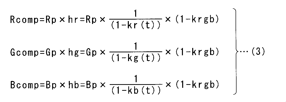
式(3)における各色のLED素子の現在輝度Rp、Gp、Bpは、各色のLED素子の初期輝度をR0、G0、B0とすると式(4)で示される。
The current brightness Rp, Gp, Bp of the LED elements of each color in the formula (3) is expressed by the formula (4) when the initial brightness of the LED elements of each color is R0, G0, B0.

式(4)を式(3)に代入すれば、各色のLED素子の輝度補正後の輝度Rcomp、Gcomp、Bcompは式(5)で示される。式(5)に示されるように、各色のLED素子の輝度補正後の輝度Rcomp、Gcomp、Bcompは、初期輝度R0、G0、B0に対して最大輝度低下率krgbで統一的に補正されたものとなる。
Substituting equation (4) into equation (3), luminance Rcomp, Gcomp, and Bcomp after luminance correction of the LED elements of the respective colors are expressed by equation (5). As shown in Expression (5), the luminance Rcomp, Gcomp, and Bcomp after the luminance correction of the LED elements of the respective colors are uniformly corrected with the maximum luminance reduction rate krgb with respect to the initial luminances R0, G0, and B0. It becomes.

以上のようにして、輝度補正係数算出部12は、表示部10に備わる各色のLED素子の全てに対して輝度補正係数hr、hg、hbを算出する。
As described above, the luminance correction coefficient calculation unit 12 calculates the luminance correction coefficients hr, hg, and hb for all the LED elements of each color provided in the display unit 10.
次に、輝度補正係数算出部12は、温度記憶部41,42を参照して、表示部10に備わる各色のLED素子の全てに対して、温度差異Tr、Tg、Tbを算出する。そして、輝度補正係数算出部12は、温度差異による輝度低下率の誤差を温度補正関数gα(t)、bα(t)、rα(t)により補正する。各色のLED素子の輝度Rcomp、Gcomp、Bcompの温度誤差をさらに補正した輝度Rcomp2、Gcomp2、Bcomp2は式(6)で示される。つまり、温度誤差が補正された輝度補正係数hr2、hg2、hb2は式(7)で示される。
Next, the luminance correction coefficient calculation unit 12 refers to the temperature storage units 41 and 42 and calculates temperature differences Tr, Tg, and Tb for all the LED elements of each color provided in the display unit 10. Then, the luminance correction coefficient calculation unit 12 corrects the error of the luminance reduction rate due to the temperature difference using the temperature correction functions gα (t), bα (t), and rα (t). Luminances Rcomp2, Gcomp2, and Bcomp2 obtained by further correcting the temperature errors of the luminances Rcomp, Gcomp, and Bcomp of the LED elements of the respective colors are expressed by Expression (6). That is, the luminance correction coefficients hr2, hg2, and hb2 in which the temperature error is corrected are expressed by Expression (7).
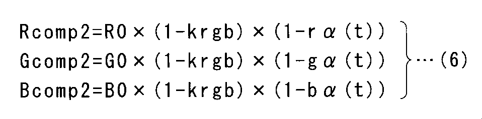
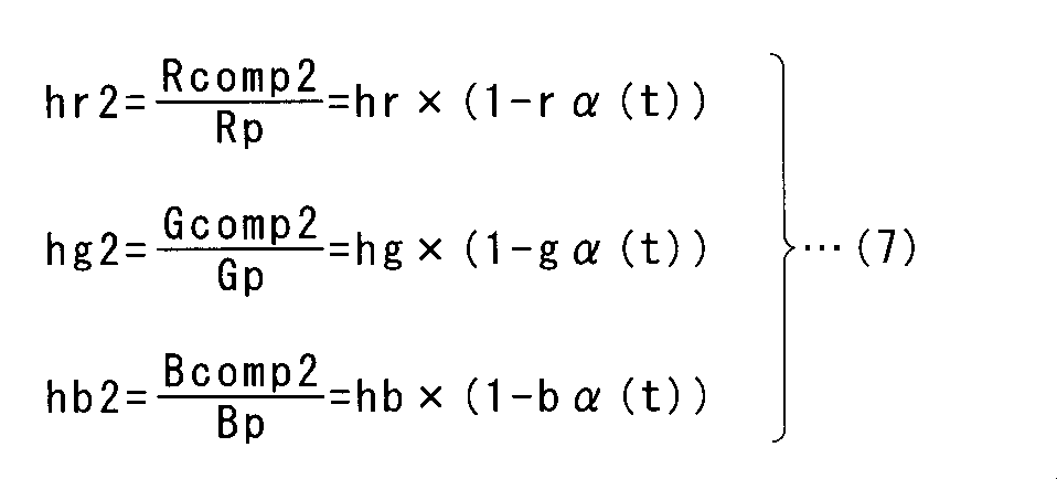
ここで、Tr≧rα1、Tg≧gα1、Tb≧bα1の場合は、温度差異による輝度低下率への影響があり、Tr<rα1、Tg<gα1、Tb<bα1の場合は、温度差異による輝度低下率への影響が無視できるとする。つまり、補正係数、gα(t)、bα(t)、rα(t)は、Tr≧rα1、Tg≧gα1、Tb≧bα1の場合のみ適用し、Tr<rα1、Tg<gα1、Tb<bα1の場合は、式(6)および式(7)において、rα(t)=gα(t)=bα(t)=0とする。
Here, when Tr ≧ rα1, Tg ≧ gα1, and Tb ≧ bα1, there is an influence on the luminance reduction rate due to the temperature difference, and when Tr <rα1, Tg <gα1, Tb <bα1, the luminance decrease due to the temperature difference. Assume that the impact on the rate is negligible. That is, the correction coefficients gα (t), bα (t), and rα (t) are applied only when Tr ≧ rα1, Tg ≧ gα1, Tb ≧ bα1, and Tr <rα1, Tg <gα1, and Tb <bα1. In this case, rα (t) = gα (t) = bα (t) = 0 in the equations (6) and (7).
以上説明したように、本実施の形態1では、表示部13に備わる各LED素子の輝度を、最も輝度低下の大きいLED素子の輝度に統一するように輝度補正を行ったが、図11に示すように、各LED素子の輝度を上昇させて初期輝度を維持するように輝度補正を行ってもよい。この場合、各色のLED素子の初期輝度R0、G0、B0を最大輝度の例えば50%に設定する。
As described above, in the first embodiment, the luminance correction is performed so that the luminance of each LED element provided in the display unit 13 is unified with the luminance of the LED element having the greatest luminance decrease. As described above, the luminance correction may be performed so as to maintain the initial luminance by increasing the luminance of each LED element. In this case, the initial luminances R0, G0, B0 of the LED elements of the respective colors are set to, for example, 50% of the maximum luminance.
輝度補正係数算出部12は、各LED素子に対して累積点灯時間記憶部6および輝度低下率記憶部11を参照することによって輝度低下率を求める。そして、輝度補正係数算出部12は、各LED素子の輝度が初期輝度になるように、輝度補正係数を算出する。
The luminance correction coefficient calculation unit 12 obtains the luminance reduction rate by referring to the cumulative lighting time storage unit 6 and the luminance reduction rate storage unit 11 for each LED element. Then, the luminance correction coefficient calculation unit 12 calculates the luminance correction coefficient so that the luminance of each LED element becomes the initial luminance.
各色のLED素子の現在の輝度をそれぞれRp、Gp、Bp、それぞれの累積点灯時間tにおける各色の輝度低下率をkr(t)、kg(t)、kb(t)、最大輝度低下率をkrgb、輝度補正係数をhr、hg、hbとすると、各色のLED素子の輝度補正後の輝度Rcomp、Gcomp、Bcompは以下の式(8)で示される。
The current luminance of the LED elements of each color is Rp, Gp, Bp, the luminance reduction rate of each color at each cumulative lighting time t is kr (t), kg (t), kb (t), and the maximum luminance reduction rate is krgb. When the luminance correction coefficients are hr, hg, and hb, the luminance Rcomp, Gcomp, and Bcomp after the luminance correction of the LED elements of the respective colors are expressed by the following formula (8).

式(4)を式(8)に代入すれば、各色のLED素子の輝度補正後の輝度Rcomp、Gcomp、Bcompは式(9)で示される。式(9)に示されるように、各色のLED素子の輝度補正後の輝度は、初期値に補正されたものとなる。
Substituting equation (4) into equation (8), luminance Rcomp, Gcomp, and Bcomp after luminance correction of the LED elements of the respective colors are expressed by equation (9). As shown in Expression (9), the luminance after luminance correction of the LED elements of the respective colors is corrected to the initial value.
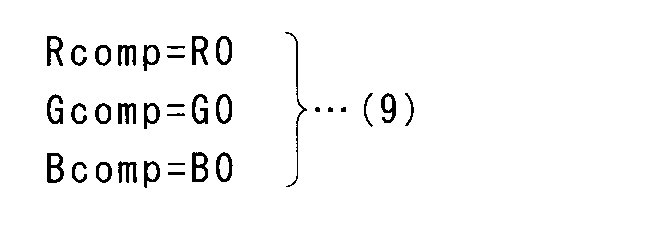
次に、輝度補正係数算出部12は、温度記憶部41,42を参照して、表示部10に備わる各色のLED素子の全てに対して、温度差異Tr、Tg、Tbを算出する。そして、輝度補正係数算出部12は、温度差異による輝度低下率の誤差を温度補正関数gα(t)、bα(t)、rα(t)により補正する。各色のLED素子の輝度Rcomp、Gcomp、Bcompの温度誤差をさらに補正した輝度Rcomp2、Gcomp2、Bcomp2は式(10)で示される。つまり、温度誤差が補正された輝度補正係数hr2、hg2、hb2は式(11)で示される。
Next, the luminance correction coefficient calculation unit 12 refers to the temperature storage units 41 and 42 and calculates temperature differences Tr, Tg, and Tb for all the LED elements of each color provided in the display unit 10. Then, the luminance correction coefficient calculation unit 12 corrects the error of the luminance reduction rate due to the temperature difference using the temperature correction functions gα (t), bα (t), and rα (t). The luminances Rcomp2, Gcomp2, and Bcomp2 obtained by further correcting the temperature errors of the luminances Rcomp, Gcomp, and Bcomp of the LED elements of the respective colors are expressed by Expression (10). That is, the luminance correction coefficients hr2, hg2, and hb2 in which the temperature error is corrected are expressed by Expression (11).


なお、上述したように補正係数、gα(t)、bα(t)、rα(t)は、Tr≧rα1、Tg≧gα1、Tb≧bα1の場合のみ適用し、Tr<rα1、Tg<gα1、Tb<bα1の場合は、式(6)および式(7)において、rα(t)=gα(t)=bα(t)=0とする。
As described above, the correction coefficients gα (t), bα (t), and rα (t) are applied only when Tr ≧ rα1, Tg ≧ gα1, Tb ≧ bα1, and Tr <rα1, Tg <gα1, In the case of Tb <bα1, rα (t) = gα (t) = bα (t) = 0 in the equations (6) and (7).
図9のステップ3における、第1、第2のエージング表示部21,22に対する故障判定方法を説明する。ここでは、第1のエージング表示部21に対する故障判定を説明する。第1のエージング表示部21に測定用LED素子が1個だけ備わっている場合、その測定用LED素子が不点灯となった場合に故障と判定する。第1のエージング表示部21に測定用LED素子が複数備わっている場合は、1個の測定用LED素子が不点灯となり、他の測定用LED素子が点灯している状況も想定する必要がある。
A failure determination method for the first and second aging display units 21 and 22 in step 3 of FIG. 9 will be described. Here, the failure determination for the first aging display unit 21 will be described. When the first aging display unit 21 is provided with only one measurement LED element, it is determined that a failure occurs when the measurement LED element is not lit. When the first aging display unit 21 includes a plurality of measurement LED elements, it is necessary to assume a situation where one measurement LED element is not lit and other measurement LED elements are lit. .
例えば、第1のエージング表示部21が測定用LED素子を4個備えるとすると、1個の測定用LED素子が不点灯となると、輝度測定部9が測定する輝度は、約25%(=1/4)低下する。従って、故障の判定に用いる輝度低下率の閾値を、1個の測定用LED素子の不点灯を判定出来る値(例えば25%)以下にする。言い換えると、第1のエージング表示部21に備わる測定用LED素子の個数をN個とすると、閾値は(100-((N-1)/N×100))以下にすればよい。
For example, if the first aging display unit 21 includes four measurement LED elements, when one measurement LED element is not lit, the luminance measured by the luminance measurement unit 9 is about 25% (= 1). / 4) Decrease. Therefore, the threshold value of the luminance reduction rate used for the failure determination is set to a value (for example, 25%) or less that can determine the non-lighting of one measurement LED element. In other words, if the number of measurement LED elements provided in the first aging display unit 21 is N, the threshold value may be set to (100 − ((N−1) / N × 100)) or less.
なお、本実施の形態1では、各LED素子に対して算出された輝度補正係数に基づいて映像信号処理部3の出力を補正したが、補正する対象は映像信号処理部3の出力に限定されない。各LED素子の駆動信号のデューティ比又は駆動電流が補正係数に基づいて最終的に補正されていれば良い。
In the first embodiment, the output of the video signal processing unit 3 is corrected based on the luminance correction coefficient calculated for each LED element. However, the correction target is not limited to the output of the video signal processing unit 3. . It suffices if the duty ratio or drive current of the drive signal of each LED element is finally corrected based on the correction coefficient.
また、本実施の形態1では、第1、第2のエージング表示部21,22に備わる測定用LED素子は、表示部10に備わるLED素子と同等であると説明した。LED素子は製造ロットにより輝度、波長のばらつきが変化する。またLED素子は輝度、波長などによりBINコードなどにより分類されている。輝度低下率の補正の精度を向上させるために、表示部10に備わるLED素子と、第1、第2のエージング表示部21,22に備わる測定用LED素子とは、同一の製造ロットおよび同一のBINコードであることが好ましい。
In the first embodiment, it has been described that the measurement LED elements provided in the first and second aging display units 21 and 22 are equivalent to the LED elements provided in the display unit 10. LED elements vary in luminance and wavelength depending on the production lot. The LED elements are classified by BIN code or the like according to luminance, wavelength or the like. In order to improve the accuracy of correction of the luminance reduction rate, the LED element provided in the display unit 10 and the measurement LED elements provided in the first and second aging display units 21 and 22 are the same in the same production lot and the same A BIN code is preferred.
また、本実施の形態1では、温度補正関数rα(t)、gα(t)、bα(t)を予め定めておき、温度差異による輝度低下率への影響が有る場合に補正を行った。温度差異が小さい場合の温度補正関数rα1(t)、gα1(t)、bα1(t)と、温度差異が小さい場合の温度補正関数rα2(t)、gα2(t)、bα2(t)とを予め定めておくことにより、より精度の高い補正が可能となる。例えば、小さい閾値rα1、gα1、bα1と大きい閾値rα2、gα2、bα2を設定しておきTr<rα1、Tg<gα1、Tb<bα1の場合、温度差異による影響が無視できるとする。rα1≦Tr<rα2、gα1≦Tg<gα2、bα1≦Tb<bα2の場合、温度補正関数rα1(t)、gα1(t)、bα1(t)を用いて輝度低下率の補正を行う。Tr≧rα2、Tg≧gα2、Tb≧bα2の場合、温度補正関数rα2(t)、gα2(t)、bα2(t)を用いて輝度低下率の補正を行う。このように、温度差異の大小に応じて、複数の温度補正関数を用いて補正を行うことにより、より高精度に温度差異による輝度低下率の差を補正することが可能となる。
In the first embodiment, the temperature correction functions rα (t), gα (t), and bα (t) are determined in advance, and correction is performed when there is an influence on the luminance reduction rate due to the temperature difference. Temperature correction functions rα1 (t), gα1 (t), bα1 (t) when the temperature difference is small, and temperature correction functions rα2 (t), gα2 (t), bα2 (t) when the temperature difference is small By determining in advance, more accurate correction is possible. For example, when the small threshold values rα1, gα1, and bα1 and the large threshold values rα2, gα2, and bα2 are set and Tr <rα1, Tg <gα1, and Tb <bα1, the influence of the temperature difference can be ignored. When rα1 ≦ Tr <rα2, gα1 ≦ Tg <gα2, and bα1 ≦ Tb <bα2, the luminance reduction rate is corrected using the temperature correction functions rα1 (t), gα1 (t), and bα1 (t). When Tr ≧ rα2, Tg ≧ gα2, and Tb ≧ bα2, the luminance reduction rate is corrected using the temperature correction functions rα2 (t), gα2 (t), bα2 (t). As described above, by performing correction using a plurality of temperature correction functions according to the magnitude of the temperature difference, it is possible to correct the difference in luminance reduction rate due to the temperature difference with higher accuracy.
また、本実施の形態1では、表示部10に備わるLED素子のそれぞれについて、温度差異と閾値の比較を行って温度補正関数による補正を行うか否かの判定を行ったが、表示部10の表示領域を予め複数の領域に分割しておいて、各領域ごとに判定を行ってもよい。つまり、各領域の代表のLED素子について、温度差異と閾値の比較を行って温度補正関数による補正を行うか否かの判定を行い、その判定結果を、その領域に配置された全てのLED素子に適用してもよい。表示部10の表示領域の分割パターンは、表示領域におけるLED素子の温度勾配を参照して決定するのが良い。
Further, in the first embodiment, for each of the LED elements included in the display unit 10, the temperature difference is compared with the threshold value to determine whether or not the correction using the temperature correction function is performed. The display area may be divided into a plurality of areas in advance, and the determination may be performed for each area. That is, with respect to the representative LED elements in each region, it is determined whether or not the correction by the temperature correction function is performed by comparing the temperature difference and the threshold value, and the determination result is determined for all the LED elements arranged in the region. You may apply to. The division pattern of the display area of the display unit 10 is preferably determined with reference to the temperature gradient of the LED elements in the display area.
また、本実施の形態1のLED表示装置100は2つのエージング表示部(即ち第1、第2のエージング表示部21,22)を備える構成としたが、不慮の故障を想定して、例えば3つのエージング表示部を備える構成としてもよい。3つ以上エージング表示部を備える構成とすることで、LED表示装置100のエージング表示部の故障に対する信頼性をさらに向上させることが可能である。
The LED display device 100 according to the first embodiment is configured to include two aging display units (that is, the first and second aging display units 21 and 22). It is good also as a structure provided with one aging display part. By adopting a configuration including three or more aging display units, it is possible to further improve the reliability against failure of the aging display unit of the LED display device 100.
また、本実施の形態1では、映像信号処理部3、輝度補正係数算出部12、輝度補正部4、累積点灯時間記憶部6および第1、第2のエージング表示部21,22を、表示部10に備わる表示モジュールの外部に設けることで、本発明を既存の表示モジュールに適用することが可能となる。なお、これら各部を表示モジュール内に設けることも可能である。
In the first embodiment, the video signal processing unit 3, the luminance correction coefficient calculation unit 12, the luminance correction unit 4, the cumulative lighting time storage unit 6, and the first and second aging display units 21 and 22 are displayed on the display unit. By providing outside the display module 10, the present invention can be applied to an existing display module. Note that these units can be provided in the display module.
<効果>
本実施の形態1におけるLED表示装置100は、複数のLED素子を備える表示モジュールを、少なくとも1つ備える表示部10と、映像信号処理部3から受ける映像信号に基づいて表示部10に備わる複数のLED素子を駆動する第1の駆動部5と、表示部10の温度を検出する第1の温度検出部31と、LED素子と同等の測定用LED素子を少なくとも1つ備える第1のエージング表示部21と、LED素子と同等の測定用LED素子を少なくとも1つ備える第2のエージング表示部22と、第1のエージング表示部21および第2のエージング表示部22に備わる測定用LED素子を駆動する第2の駆動部8と、第1のエージング表示部21および第2のエージング表示部22に備わる測定用LED素子の輝度を測定する輝度測定部9と、第1のエージング表示部21および第2のエージング表示部22のそれぞれの温度を検出する第2の温度検出部32と、表示部10に備わる複数のLED素子のそれぞれに関して、累積点灯時間を記憶する累積点灯時間記憶部6と、第1のエージング表示部21および第2のエージング表示部22に備わる測定用LED素子の累積点灯時間と、輝度測定部9の測定結果に基づく測定用LED素子の輝度低下率との関係を記憶する輝度低下率記憶部11と、表示部10に備わる複数のLED素子のそれぞれに関して、累積点灯時間記憶部6および輝度低下率記憶部11を参照して、輝度補正係数を算出する輝度補正係数算出部12と、輝度補正係数に基づいて複数のLED素子それぞれの輝度を補正するように第1の駆動部5を制御する輝度補正部4と、を備え、輝度補正係数算出部12は、第1の温度検出部31が検出した温度および第2の温度検出部32が検出した温度に基づいて、表示部10に備わる複数のLED素子のそれぞれの輝度補正係数を補正する。 <Effect>
TheLED display device 100 according to the first embodiment includes a display unit 10 including at least one display module including a plurality of LED elements and a plurality of display units 10 provided on the basis of a video signal received from the video signal processing unit 3. 1st drive part 5 which drives an LED element, 1st temperature detection part 31 which detects the temperature of display part 10, and the 1st aging display part provided with at least 1 LED element for measurement equivalent to an LED element 21, the second aging display unit 22 including at least one measurement LED element equivalent to the LED element, and the measurement LED elements provided in the first aging display unit 21 and the second aging display unit 22 are driven. Luminance measurement for measuring the luminance of the LED elements for measurement provided in the second drive unit 8, the first aging display unit 21 and the second aging display unit 22 9, the second temperature detection unit 32 that detects the temperature of each of the first aging display unit 21 and the second aging display unit 22, and each of the plurality of LED elements included in the display unit 10, LED for measurement based on the cumulative lighting time storage unit 6 for storing the cumulative lighting time of the LED elements for measurement provided in the first aging display unit 21 and the second aging display unit 22 and the measurement result of the luminance measurement unit 9 With respect to each of the plurality of LED elements included in the display unit 10 and the luminance reduction rate storage unit 11 that stores the relationship with the luminance reduction rate of the element, refer to the cumulative lighting time storage unit 6 and the luminance reduction rate storage unit 11, A luminance correction coefficient calculation unit 12 that calculates a luminance correction coefficient, and controls the first drive unit 5 to correct the luminance of each of the plurality of LED elements based on the luminance correction coefficient. A luminance correction unit 4, and the luminance correction coefficient calculation unit 12 is provided in the display unit 10 based on the temperature detected by the first temperature detection unit 31 and the temperature detected by the second temperature detection unit 32. The brightness correction coefficient of each of the LED elements is corrected.
本実施の形態1におけるLED表示装置100は、複数のLED素子を備える表示モジュールを、少なくとも1つ備える表示部10と、映像信号処理部3から受ける映像信号に基づいて表示部10に備わる複数のLED素子を駆動する第1の駆動部5と、表示部10の温度を検出する第1の温度検出部31と、LED素子と同等の測定用LED素子を少なくとも1つ備える第1のエージング表示部21と、LED素子と同等の測定用LED素子を少なくとも1つ備える第2のエージング表示部22と、第1のエージング表示部21および第2のエージング表示部22に備わる測定用LED素子を駆動する第2の駆動部8と、第1のエージング表示部21および第2のエージング表示部22に備わる測定用LED素子の輝度を測定する輝度測定部9と、第1のエージング表示部21および第2のエージング表示部22のそれぞれの温度を検出する第2の温度検出部32と、表示部10に備わる複数のLED素子のそれぞれに関して、累積点灯時間を記憶する累積点灯時間記憶部6と、第1のエージング表示部21および第2のエージング表示部22に備わる測定用LED素子の累積点灯時間と、輝度測定部9の測定結果に基づく測定用LED素子の輝度低下率との関係を記憶する輝度低下率記憶部11と、表示部10に備わる複数のLED素子のそれぞれに関して、累積点灯時間記憶部6および輝度低下率記憶部11を参照して、輝度補正係数を算出する輝度補正係数算出部12と、輝度補正係数に基づいて複数のLED素子それぞれの輝度を補正するように第1の駆動部5を制御する輝度補正部4と、を備え、輝度補正係数算出部12は、第1の温度検出部31が検出した温度および第2の温度検出部32が検出した温度に基づいて、表示部10に備わる複数のLED素子のそれぞれの輝度補正係数を補正する。 <Effect>
The
本実施の形態1におけるLED表示装置100は画像などを表示する表示部10とは別に、エージング表示部(第1、第2のエージング表示部21,22)を備える。そして、エージング表示部に配置された測定用LED素子の輝度低下率が実時間で計測される。表示部10に備わる各LED素子の累積点灯時間における測定用LED素子の輝度低下率を参照することで、各LED素子の輝度低下率を求めることが可能である。そして、各LED素子の輝度低下率に基づいて輝度補正係数を算出することにより、各LED素子の輝度を均一に保つことが可能である。本実施の形態1ではさらに、表示部10と、エージング表示部との温度差による輝度低下率の差異を考慮して、輝度補正係数が補正される。従って、表示部10が備える複数のLED素子のそれぞれに関して極めて精度の高い輝度補正が可能となるため、長期の運用において表示部10の輝度の均一性および色均一性を維持することが可能となる。
The LED display device 100 according to the first embodiment includes an aging display unit (first and second aging display units 21 and 22) separately from the display unit 10 that displays an image and the like. And the brightness | luminance fall rate of the LED element for a measurement arrange | positioned at an aging display part is measured in real time. It is possible to obtain the luminance reduction rate of each LED element by referring to the luminance reduction rate of the LED element for measurement during the cumulative lighting time of each LED element provided in the display unit 10. And it is possible to keep the brightness | luminance of each LED element uniform by calculating a brightness | luminance correction coefficient based on the brightness | luminance fall rate of each LED element. In the first embodiment, the luminance correction coefficient is further corrected in consideration of the difference in luminance reduction rate due to the temperature difference between the display unit 10 and the aging display unit. Accordingly, it is possible to perform highly accurate luminance correction for each of the plurality of LED elements included in the display unit 10, so that the luminance uniformity and color uniformity of the display unit 10 can be maintained in a long-term operation. .
また、エージング表示部を1つだけ配置した場合、エージング表示部の故障により、測定用LED素子の不点灯又は輝度の著しい低下が発生すると、エージング表示部から正確な輝度低下率を得ることができなる。従って、表示部10の輝度補正を正しく行うことができなくなる。そこで、本実施の形態1では、第1、第2のエージング表示部21,22を配置する。これにより、どちらかのエージング表示部が故障しても、もう一方のエージング表示部から得られる正確な輝度低下率および温度を利用することによって、表示部10の輝度補正を正しく行うことができる。従って、長期運用において表示部10の輝度を安定して均一に保つことができる。
In addition, when only one aging display unit is disposed, if the measurement LED element is not lit or a significant decrease in luminance occurs due to a failure of the aging display unit, an accurate luminance reduction rate can be obtained from the aging display unit. Become. Therefore, the luminance correction of the display unit 10 cannot be performed correctly. Therefore, in the first embodiment, the first and second aging display units 21 and 22 are arranged. Thereby, even if one of the aging display units breaks down, the luminance correction of the display unit 10 can be performed correctly by using the accurate luminance reduction rate and temperature obtained from the other aging display unit. Therefore, the luminance of the display unit 10 can be kept stable and uniform during long-term operation.
また、本実施の形態1におけるLED表示装置100において、輝度補正係数算出部12は、輝度低下率記憶部11を参照することによって、第1のエージング表示部21と第2のエージング表示部22のそれぞれについて故障を検出し、輝度補正係数算出部12は、故障を検出した場合、輝度低下率記憶部11および第2の温度検出部32に関して正常なエージング表示部に関する情報を参照して、輝度低下率を求める。
Further, in the LED display device 100 according to the first embodiment, the luminance correction coefficient calculation unit 12 refers to the luminance decrease rate storage unit 11, so that the first aging display unit 21 and the second aging display unit 22 When a failure is detected for each, the luminance correction coefficient calculation unit 12 refers to the information on the normal aging display unit with respect to the luminance decrease rate storage unit 11 and the second temperature detection unit 32 when the failure is detected. Find the rate.
従って、どちらかのエージング表示部が故障しても、もう一方のエージング表示部から得られる正確な輝度低下率を利用することによって、表示部10の輝度補正を正しく行うことができる。従って、長期運用において表示部10の輝度を安定して均一に保つことができる。
Therefore, even if one of the aging display units breaks down, the luminance correction of the display unit 10 can be performed correctly by using the accurate luminance reduction rate obtained from the other aging display unit. Therefore, the luminance of the display unit 10 can be kept stable and uniform during long-term operation.
また、本実施の形態1におけるLED表示装置100において、輝度補正係数算出部12は、第1の温度検出部31が検出した温度および第2の温度検出部32が検出した温度を参照して、予め定められた温度補正関数rα(t)、gα(t)、bα(t)に基づいて輝度補正係数を補正する。従って、温度補正関数を予め定めておくことにより、温度補正関数を用いて温度差による輝度低下率の差異を精度良く補正することが可能である。
In the LED display device 100 according to the first embodiment, the luminance correction coefficient calculation unit 12 refers to the temperature detected by the first temperature detection unit 31 and the temperature detected by the second temperature detection unit 32, The luminance correction coefficient is corrected based on predetermined temperature correction functions rα (t), gα (t), bα (t). Therefore, by determining the temperature correction function in advance, it is possible to accurately correct the difference in the luminance reduction rate due to the temperature difference using the temperature correction function.
また、本実施の形態1におけるLED表示装置100において、温度補正関数rα(t)、gα(t)、bα(t)は、LED素子と同等の2つのLED素子の温度差が予め定められた温度以上の場合における、累積点灯時間に対する輝度低下率の差を表す関数である。
In the LED display device 100 according to the first embodiment, the temperature correction functions rα (t), gα (t), and bα (t) are set in advance so that the temperature difference between two LED elements equivalent to the LED elements is predetermined. It is a function showing the difference of the brightness | luminance fall rate with respect to the accumulation lighting time in the case of more than temperature.
従って、本実施の形態1においては、LED素子と測定用LED素子との温度差が予め定められた温度未満の場合は、温度差による輝度低下率の差異が無視できるとみなして温度補正関数による補正を行わない。これにより、輝度補正係数算出部12の演算処理を軽減することが可能である。
Therefore, in the first embodiment, when the temperature difference between the LED element and the measurement LED element is less than a predetermined temperature, it is assumed that the difference in the luminance decrease rate due to the temperature difference is negligible, and the temperature correction function is used. Do not make corrections. Thereby, it is possible to reduce the calculation process of the luminance correction coefficient calculation unit 12.
また、本実施の形態1におけるLED表示装置100において、輝度補正係数算出部12は、複数のLED素子のうち、輝度低下率が最も大きいLED素子の輝度を基準として、全てのLED素子それぞれの輝度補正係数を算出する。
Further, in the LED display device 100 according to the first embodiment, the luminance correction coefficient calculation unit 12 uses the luminance of the LED element having the largest luminance reduction rate among the plurality of LED elements as a reference. A correction coefficient is calculated.
本実施の形態1によれば、図10に示す通り、表示部13に備わる各LED素子の輝度は、最も輝度低下の大きいLED素子の輝度に統一され、表示部10として、輝度均一性、ホワイトバランスを保つことができるため、輝度のばらつきが改善される。最も輝度低下の大きいLED素子の輝度に統一する輝度補正方式は、初期の輝度を高く取れる利点がある。また、従来、表示部10の輝度を輝度センサで常時計測する場合は、輝度センサにより表示部の表示画像が遮られる等の問題があった。一方、本実施の形態1によれば、表示部10とは別に、輝度測定用に第1、第2のエージング表示部21,22を配置する。従って、表示部10の表示を輝度センサによって遮ることなく、常時LED素子の経時変化を検出することができる。
According to the first embodiment, as shown in FIG. 10, the luminance of each LED element provided in the display unit 13 is unified to the luminance of the LED element having the greatest luminance reduction. Since balance can be maintained, variation in luminance is improved. The luminance correction method that unifies the luminance of the LED element having the greatest luminance reduction has an advantage that the initial luminance can be increased. Conventionally, when the luminance of the display unit 10 is constantly measured by the luminance sensor, there is a problem that the display image on the display unit is blocked by the luminance sensor. On the other hand, according to the first embodiment, the first and second aging display units 21 and 22 are arranged for luminance measurement separately from the display unit 10. Accordingly, it is possible to always detect a change with time of the LED element without blocking the display of the display unit 10 by the luminance sensor.
また、本実施の形態1におけるLED表示装置100において、輝度補正係数算出部12は、表示部10に備わる複数のLED素子のそれぞれが予め設定された輝度を維持するように、輝度補正係数を算出してもよい。
In the LED display device 100 according to the first embodiment, the luminance correction coefficient calculation unit 12 calculates the luminance correction coefficient so that each of the plurality of LED elements provided in the display unit 10 maintains a predetermined luminance. May be.
この輝度補正係数の算出方法によれば、例えば、初期輝度を予め50%に設定しておくことにより、初期輝度は低くなるものの運用中の輝度を一定に維持することができる。従って、LED表示装置100の長期運用において、表示部10の表示画像の輝度が徐々に低下することを防止することが可能である。
According to this method of calculating the luminance correction coefficient, for example, by setting the initial luminance to 50% in advance, the luminance during operation can be kept constant although the initial luminance is lowered. Therefore, in the long-term operation of the LED display device 100, it is possible to prevent the brightness of the display image on the display unit 10 from gradually decreasing.
<実施の形態2>
図12は、緑色のLED素子を異なるデューティ比で駆動した場合の輝度低下率を示す図である。図12に示すように、デューティ比が大きくなるほど、輝度低下率も大きくなる。 <Embodiment 2>
FIG. 12 is a diagram showing a luminance reduction rate when green LED elements are driven at different duty ratios. As shown in FIG. 12, the luminance reduction rate increases as the duty ratio increases.
実施の形態1では、表示部10における最大デューティ比と同じデューティ比で測定用LED素子が駆動されるとした。本実施の形態2では、第1、第2のエージング表示部21,22のそれぞれは、複数の測定用LED素子を備え、各LED素子は互いに異なるデューティ比で駆動されるとする。例えば、図12に示すように、複数の測定用LED素子のそれぞれは、100%、75%、50%、25%のデューティ比で駆動される。
In Embodiment 1, the measurement LED element is driven at the same duty ratio as the maximum duty ratio in the display unit 10. In the second embodiment, each of the first and second aging display units 21 and 22 includes a plurality of measurement LED elements, and each LED element is driven with a different duty ratio. For example, as shown in FIG. 12, each of the plurality of measurement LED elements is driven with a duty ratio of 100%, 75%, 50%, and 25%.
例えば、緑色のLED素子の最大累積点灯時間tgmaxが50Kであり、輝度低下率記憶部11には緑色の測定用LED素子に関して、図12に示す輝度低下率が記憶されているとする。この場合、輝度補正係数算出部12は、輝度低下率記憶部11を参照して、複数のデューティ比のうち、最大累積点灯時間(即ち50K)に最も近い累積点灯時間を有するデューティ比を探す。図12においては、50%のデューティ比が該当する。従って、輝度補正係数算出部12は50%のデューティ比の輝度低下率を参照して、輝度低下率(kg(tgmax))を得る。
For example, it is assumed that the maximum cumulative lighting time tgmax of the green LED element is 50K, and the luminance reduction rate storage unit 11 stores the luminance reduction rate shown in FIG. 12 for the green measurement LED element. In this case, the luminance correction coefficient calculation unit 12 refers to the luminance decrease rate storage unit 11 and searches for the duty ratio having the cumulative lighting time closest to the maximum cumulative lighting time (that is, 50K) among the plurality of duty ratios. In FIG. 12, a duty ratio of 50% corresponds. Accordingly, the luminance correction coefficient calculation unit 12 refers to the luminance reduction rate with the duty ratio of 50% to obtain the luminance reduction rate (kg (tgmax)).
本実施の形態2において、測定用LED素子の駆動方法および輝度低下率kr(trmax)、kg(tgmax)、kb(tbmax)の求め方以外は実施の形態1と同じため、説明を省略する。
In the second embodiment, since the measurement LED element driving method and the method of obtaining the luminance reduction rates kr (trmax), kg (tgmax), and kb (tbmax) are the same as those in the first embodiment, the description thereof is omitted.
<効果>
本実施の形態2におけるLED表示装置100において、第1のエージング表示部21と第2のエージング表示部22の少なくとも一方は、複数の測定用LED素子を備え、第2の駆動部8は、複数の測定用LED素子のそれぞれを互いに異なるデューティ比で駆動し、輝度低下率記憶部11は、複数の測定用LED素子の累積点灯時間と、輝度測定部9の測定結果に基づく測定用LED素子の輝度低下率との関係を、デューティ比ごとに記憶し、輝度補正係数算出部12は、LED素子の累積点灯時間に最も近い測定用LED素子の累積点灯時間の輝度低下率を参照することによって、LED素子の前記輝度低下率を求める。 <Effect>
In theLED display device 100 according to the second embodiment, at least one of the first aging display unit 21 and the second aging display unit 22 includes a plurality of measurement LED elements, and the second driving unit 8 includes a plurality of Each of the measurement LED elements is driven with a different duty ratio, and the luminance decrease rate storage unit 11 is configured to measure the accumulated LED lighting time of the plurality of measurement LED elements and the measurement LED element based on the measurement result of the luminance measurement unit 9. The relationship with the luminance reduction rate is stored for each duty ratio, and the luminance correction coefficient calculation unit 12 refers to the luminance reduction rate of the cumulative lighting time of the LED element for measurement closest to the cumulative lighting time of the LED element, The said brightness | luminance fall rate of an LED element is calculated | required.
本実施の形態2におけるLED表示装置100において、第1のエージング表示部21と第2のエージング表示部22の少なくとも一方は、複数の測定用LED素子を備え、第2の駆動部8は、複数の測定用LED素子のそれぞれを互いに異なるデューティ比で駆動し、輝度低下率記憶部11は、複数の測定用LED素子の累積点灯時間と、輝度測定部9の測定結果に基づく測定用LED素子の輝度低下率との関係を、デューティ比ごとに記憶し、輝度補正係数算出部12は、LED素子の累積点灯時間に最も近い測定用LED素子の累積点灯時間の輝度低下率を参照することによって、LED素子の前記輝度低下率を求める。 <Effect>
In the
複数の測定用LED素子のそれぞれを互いに異なるデューティ比で駆動することにより、輝度補正係数算出部12は、LED素子の駆動条件により近いデューティ比で駆動された測定用LED素子の輝度低下率を参照することが可能となる。従って、輝度補正係数算出部12は、より精度良く輝度低下率を求めることが可能となる。
By driving each of the plurality of measurement LED elements at different duty ratios, the luminance correction coefficient calculation unit 12 refers to the luminance reduction rate of the measurement LED elements driven at a duty ratio closer to the drive conditions of the LED elements. It becomes possible to do. Therefore, the luminance correction coefficient calculation unit 12 can obtain the luminance reduction rate with higher accuracy.
<実施の形態3>
図13は、本実施の形態3におけるLED表示装置100の表示部10周辺の詳しいブロック図である。実施の形態1においては、表示部10は1つの表示モジュールを備える構成とした。一方、本実施の形態3においては、図13に示すように、表示部10が複数の表示モジュールを備える構成とする。複数の表示モジュールが組み合わされて1つの画面が構成される。 <Embodiment 3>
FIG. 13 is a detailed block diagram around thedisplay unit 10 of the LED display device 100 according to the third embodiment. In the first embodiment, the display unit 10 includes one display module. On the other hand, in the third embodiment, as shown in FIG. 13, the display unit 10 includes a plurality of display modules. A plurality of display modules are combined to form one screen.
図13は、本実施の形態3におけるLED表示装置100の表示部10周辺の詳しいブロック図である。実施の形態1においては、表示部10は1つの表示モジュールを備える構成とした。一方、本実施の形態3においては、図13に示すように、表示部10が複数の表示モジュールを備える構成とする。複数の表示モジュールが組み合わされて1つの画面が構成される。 <
FIG. 13 is a detailed block diagram around the
本実施の形態3において、第1の駆動部5は、輝度補正部4から入力される映像信号から各表示モジュールに対応する領域を選択し、各表示モジュールを駆動する。複数の表示モジュールは例えばデイジーチェーン状に接続されている。また、第1の温度検出部31は、各表示モジュールに備わる複数のLED素子の温度を個別に検出する。
In the third embodiment, the first drive unit 5 selects an area corresponding to each display module from the video signal input from the luminance correction unit 4, and drives each display module. The plurality of display modules are connected in a daisy chain, for example. In addition, the first temperature detection unit 31 individually detects the temperatures of the plurality of LED elements included in each display module.
実施の形態1においては、表示部10は、1つの表示モジュールを備え、例えば図1に示すように、表示モジュールは赤、緑、青色のLED素子をそれぞれ16個、合計で48個のLED素子を備える構成とした。この場合、輝度補正係数算出部12は48個のLED素子それぞれに関して輝度補正係数を算出する。
In the first embodiment, the display unit 10 includes one display module. For example, as shown in FIG. 1, the display module includes 16 red, green, and blue LED elements, for a total of 48 LED elements. It was set as the structure provided with. In this case, the luminance correction coefficient calculation unit 12 calculates a luminance correction coefficient for each of the 48 LED elements.
本実施の形態3においては、表示部10は、例えば図13に示すように、4個の表示モジュールを備える。各表示モジュールは48個のLED素子を備えるため、表示部10は合計で192個のLED素子を備える。この場合、輝度補正係数算出部12は192個のLED素子それぞれに関して輝度補正係数を算出する。本実施の形態3における輝度補正係数の算出方法は実施の形態1と同様である。輝度補正係数により各LED素子の輝度が補正された結果、複数の表示モジュールに備わる全てのLED素子のそれぞれの輝度が互いに等しくなる。
In the third embodiment, the display unit 10 includes four display modules as shown in FIG. Since each display module includes 48 LED elements, the display unit 10 includes 192 LED elements in total. In this case, the luminance correction coefficient calculation unit 12 calculates a luminance correction coefficient for each of the 192 LED elements. The calculation method of the luminance correction coefficient in the third embodiment is the same as that in the first embodiment. As a result of correcting the brightness of each LED element by the brightness correction coefficient, the brightness of all the LED elements provided in the plurality of display modules becomes equal to each other.
つまり、表示部10が何個の表示モジュールで構成されるかに関わらず、輝度補正係数算出部12は表示部10に備わる全てのLED素子に関して輝度補正係数を算出する。本実施の形態3において、表示部10が備える表示モジュールの個数以外の構成は、実施の形態1と同じため、説明を省略する。
That is, regardless of how many display modules the display unit 10 is composed of, the luminance correction coefficient calculation unit 12 calculates luminance correction coefficients for all LED elements provided in the display unit 10. In the third embodiment, since the configuration other than the number of display modules provided in the display unit 10 is the same as that in the first embodiment, the description thereof is omitted.
<効果>
本実施の形態3におけるLED表示装置100において、表示部10は複数の表示モジュールを備え、複数の表示モジュールが組み合わされて1つの画面が構成され、第1の温度検出部31は、複数の表示モジュールのそれぞれの温度を検出し、輝度補正係数算出部12は、複数の表示モジュールに備わる全ての前記LED素子のそれぞれの輝度が互いに等しくなるように輝度補正係数を算出する。 <Effect>
In theLED display device 100 according to the third embodiment, the display unit 10 includes a plurality of display modules, and a plurality of display modules are combined to form one screen, and the first temperature detection unit 31 includes a plurality of displays. The temperature of each module is detected, and the luminance correction coefficient calculation unit 12 calculates the luminance correction coefficient so that the luminances of all the LED elements included in the plurality of display modules are equal to each other.
本実施の形態3におけるLED表示装置100において、表示部10は複数の表示モジュールを備え、複数の表示モジュールが組み合わされて1つの画面が構成され、第1の温度検出部31は、複数の表示モジュールのそれぞれの温度を検出し、輝度補正係数算出部12は、複数の表示モジュールに備わる全ての前記LED素子のそれぞれの輝度が互いに等しくなるように輝度補正係数を算出する。 <Effect>
In the
従って、表示部10は複数の表示モジュールを備え、複数の表示モジュールが組み合わされて大きい画面が構成される場合であっても、実施の形態1と同様に極めて精度の高い輝度補正が可能となるため、長期の運用において大画面の輝度の均一性および色均一性を維持することが可能となる。
Therefore, even when the display unit 10 includes a plurality of display modules and a large screen is configured by combining the plurality of display modules, luminance correction with extremely high accuracy can be performed as in the first embodiment. Therefore, it is possible to maintain the luminance uniformity and color uniformity of a large screen in a long-term operation.
さらに、累積点灯時間記憶部6および輝度補正係数算出部12を表示部10の外部に配置することにより、表示部10において一部の表示モジュールが交換された場合であっても、表示部10全体の輝度補正を行うことが可能である。従って、長期の運用において表示モジュールの交換が行われた場合であっても、大画面の輝度の均一性および色均一性を維持することが可能となる。
Furthermore, by arranging the cumulative lighting time storage unit 6 and the luminance correction coefficient calculation unit 12 outside the display unit 10, the entire display unit 10 can be used even when some display modules are replaced in the display unit 10. It is possible to perform luminance correction. Accordingly, even when the display module is replaced in a long-term operation, it is possible to maintain the luminance uniformity and color uniformity of the large screen.
なお、本発明は、その発明の範囲内において、各実施の形態を自由に組み合わせたり、各実施の形態を適宜、変形、省略することが可能である。この発明は詳細に説明されたが、上記した説明は、すべての局面において、例示であって、この発明がそれに限定されるものではない。例示されていない無数の変形例が、この発明の範囲から外れることなく想定され得るものと解される。
It should be noted that the present invention can be freely combined with each other within the scope of the invention, and each embodiment can be appropriately modified or omitted. Although the present invention has been described in detail, the above description is illustrative in all aspects, and the present invention is not limited thereto. It is understood that countless variations that are not illustrated can be envisaged without departing from the scope of the present invention.
2 入力端子、3 映像信号処理部、4 輝度補正部、5 第1の駆動部、6 累積点灯時間記憶部、7 駆動データ生成部、8 第2の駆動部、9,91,92 輝度測定部、10 表示部、11 輝度低下率記憶部、12 輝度補正係数算出部、21 第1のエージング表示部、22 第1のエージング表示部、31 第1の温度検出部、32 第2の温度検出部、321,322 温度検出部、41,42 温度記憶部、100 LED表示装置、HW1 入力インターフェース、HW2 処理回路、HW3 メモリ、HW4 記憶装置、HW5 第1の駆動回路、HW6 表示装置、HW7 第1の温度検出装置、HW8 第2の駆動回路、HW9 第1のエージング表示装置、HW10 第2のエージング表示装置、HW11 輝度測定装置、HW12 第1の温度検出装置。
2 input terminal, 3 video signal processing unit, 4 luminance correction unit, 5 first drive unit, 6 cumulative lighting time storage unit, 7 drive data generation unit, 8 second drive unit, 9, 91, 92 luminance measurement unit DESCRIPTION OF SYMBOLS 10 Display part, 11 Brightness reduction rate memory | storage part, 12 Brightness correction coefficient calculation part, 21 1st aging display part, 22 1st aging display part, 31 1st temperature detection part, 32 2nd temperature detection part , 321, 322 temperature detection unit, 41, 42 temperature storage unit, 100 LED display device, HW1 input interface, HW2 processing circuit, HW3 memory, HW4 storage device, HW5 first drive circuit, HW6 display device, HW7 first Temperature detection device, HW8 second drive circuit, HW9 first aging display device, HW10 second aging display device, HW11 Degree measuring apparatus, HW12 first temperature sensing device.
Claims (9)
- 複数のLED素子を備える表示モジュールを、少なくとも1つ備える表示部(10)と、
映像信号処理部(3)から受ける映像信号に基づいて前記表示部(10)に備わる前記複数のLED素子を駆動する第1の駆動部(5)と、
前記表示部(10)の温度を検出する第1の温度検出部(31)と、
前記LED素子と同等の測定用LED素子を少なくとも1つ備える第1のエージング表示部(21)と、
前記LED素子と同等の測定用LED素子を少なくとも1つ備える第2のエージング表示部(22)と、
前記第1のエージング表示部(21)および第2のエージング表示部(22)に備わる前記測定用LED素子を駆動する第2の駆動部(8)と、
前記第1のエージング表示部(21)および第2のエージング表示部(22)に備わる前記測定用LED素子の輝度を測定する輝度測定部(9)と、
前記第1のエージング表示部(21)および第2のエージング表示部(22)のそれぞれの温度を検出する第2の温度検出部(32)と、
前記表示部(10)に備わる前記複数のLED素子のそれぞれに関して、累積点灯時間を記憶する累積点灯時間記憶部(6)と、
前記第1のエージング表示部(21)および前記第2のエージング表示部(22)に備わる前記測定用LED素子の累積点灯時間と、前記輝度測定部(9)の測定結果に基づく前記測定用LED素子の輝度低下率との関係を記憶する輝度低下率記憶部(11)と、
前記表示部(10)に備わる前記複数のLED素子のそれぞれに関して、前記累積点灯時間記憶部(6)および前記輝度低下率記憶部(11)を参照して、輝度補正係数を算出する輝度補正係数算出部(12)と、
前記輝度補正係数に基づいて前記複数のLED素子それぞれの輝度を補正するように前記第1の駆動部(5)を制御する輝度補正部(4)と、
を備え、
前記輝度補正係数算出部(12)は、前記第1の温度検出部(31)が検出した温度および前記第2の温度検出部(32)が検出した温度に基づいて、前記表示部(10)に備わる前記複数のLED素子のそれぞれの前記輝度補正係数を補正する、
LED表示装置(100)。 A display unit (10) including at least one display module including a plurality of LED elements;
A first drive unit (5) for driving the plurality of LED elements included in the display unit (10) based on a video signal received from the video signal processing unit (3);
A first temperature detection unit (31) for detecting the temperature of the display unit (10);
A first aging indicator (21) comprising at least one LED element for measurement equivalent to the LED element;
A second aging indicator (22) comprising at least one LED element for measurement equivalent to the LED element;
A second drive unit (8) for driving the LED element for measurement provided in the first aging display unit (21) and the second aging display unit (22);
A luminance measuring unit (9) for measuring the luminance of the LED element for measurement provided in the first aging display unit (21) and the second aging display unit (22);
A second temperature detection section (32) for detecting the respective temperatures of the first aging display section (21) and the second aging display section (22);
A cumulative lighting time storage unit (6) for storing a cumulative lighting time for each of the plurality of LED elements provided in the display unit (10);
The measurement LED based on the accumulated lighting time of the LED element for measurement provided in the first aging display unit (21) and the second aging display unit (22) and the measurement result of the luminance measurement unit (9) A luminance reduction rate storage unit (11) for storing a relationship with the luminance reduction rate of the element;
A luminance correction coefficient for calculating a luminance correction coefficient with reference to the cumulative lighting time storage unit (6) and the luminance decrease rate storage unit (11) for each of the plurality of LED elements provided in the display unit (10). A calculation unit (12);
A luminance correction unit (4) for controlling the first drive unit (5) to correct the luminance of each of the plurality of LED elements based on the luminance correction coefficient;
With
The brightness correction coefficient calculation unit (12) is configured to display the display unit (10) based on the temperature detected by the first temperature detection unit (31) and the temperature detected by the second temperature detection unit (32). Correcting the brightness correction coefficient of each of the plurality of LED elements included in
LED display device (100). - 前記少なくとも1つの表示モジュールは複数であり、
複数の前記表示モジュールが組み合わされて1つの画面が構成され、
前記第1の温度検出部(31)は、複数の前記表示モジュールのそれぞれの温度を検出し、
輝度補正係数算出部(12)は、複数の前記表示モジュールに備わる全ての前記LED素子のそれぞれの輝度が互いに等しくなるように前記輝度補正係数を算出する、
請求項1に記載のLED表示装置(100)。 A plurality of the at least one display module;
A plurality of the display modules are combined to form one screen,
The first temperature detector (31) detects the temperature of each of the plurality of display modules,
A luminance correction coefficient calculation unit (12) calculates the luminance correction coefficient so that the luminances of all the LED elements included in the plurality of display modules are equal to each other;
The LED display device (100) according to claim 1. - 前記輝度補正係数算出部(12)は、前記輝度低下率記憶部(11)を参照することによって、前記第1のエージング表示部(21)と第2のエージング表示部(22)のそれぞれについて故障を検出し、
前記輝度補正係数算出部(12)は、故障を検出した場合、前記輝度低下率記憶部(11)および前記第2の温度検出部(32)に関して正常なエージング表示部に関する情報を参照して、前記輝度低下率を求める、
請求項1又は請求項2に記載のLED表示装置(100)。 The luminance correction coefficient calculation unit (12) refers to the luminance decrease rate storage unit (11), thereby causing a failure in each of the first aging display unit (21) and the second aging display unit (22). Detect
When the luminance correction coefficient calculation unit (12) detects a failure, the luminance correction coefficient calculation unit (12) refers to information regarding a normal aging display unit with respect to the luminance decrease rate storage unit (11) and the second temperature detection unit (32). Obtaining the luminance reduction rate;
The LED display device (100) according to claim 1 or 2. - 輝度補正係数算出部(12)は、前記第1の温度検出部(31)が検出した温度および前記第2の温度検出部(32)が検出した温度を参照して、予め定められた温度補正関数に基づいて前記輝度補正係数を補正する、
請求項1から請求項3のいずれか一項に記載のLED表示装置(100)。 The luminance correction coefficient calculation unit (12) refers to the temperature detected by the first temperature detection unit (31) and the temperature detected by the second temperature detection unit (32), and is set in advance as a temperature correction. Correcting the brightness correction coefficient based on a function;
The LED display device (100) according to any one of claims 1 to 3. - 前記温度補正関数は、前記LED素子と同等の2つのLED素子の温度差が予め定められた温度よりも大きい場合における、累積点灯時間に対する輝度低下率の差を表す関数である、
請求項4に記載のLED表示装置(100)。 The temperature correction function is a function that represents a difference in luminance decrease rate with respect to cumulative lighting time when a temperature difference between two LED elements equivalent to the LED elements is larger than a predetermined temperature.
The LED display device (100) according to claim 4. - 前記輝度補正係数算出部(12)は、前記複数のLED素子のうち、前記輝度低下率が最も大きい前記LED素子の輝度を基準として、全ての前記LED素子それぞれの輝度補正係数を算出する、
請求項1から請求項5のいずれか一項に記載のLED表示装置(100)。 The brightness correction coefficient calculation unit (12) calculates a brightness correction coefficient for each of all the LED elements based on the brightness of the LED element having the largest brightness reduction rate among the plurality of LED elements.
The LED display device (100) according to any one of claims 1 to 5. - 輝度補正係数算出部(12)は、前記表示部に備わる前記複数のLED素子のそれぞれが予め設定された輝度を維持するように、前記輝度補正係数を算出する、
請求項1から請求項5のいずれか一項に記載のLED表示装置(100)。 A luminance correction coefficient calculating unit (12) that calculates the luminance correction coefficient so that each of the plurality of LED elements included in the display unit maintains a predetermined luminance;
The LED display device (100) according to any one of claims 1 to 5. - 前記第1のエージング表示部(21)と前記第2のエージング表示部の少なくとも一方は、複数の前記測定用LED素子を備え、
前記第2の駆動部(8)は、複数の前記測定用LED素子のそれぞれを互いに異なるデューティ比で駆動し、
前記輝度低下率記憶部(11)は、複数の前記測定用LED素子の累積点灯時間と、前記輝度測定部の測定結果に基づく前記測定用LED素子の輝度低下率との関係を、デューティ比ごとに記憶し、
輝度補正係数算出部(12)は、前記LED素子の前記累積点灯時間に最も近い前記測定用LED素子の累積点灯時間の輝度低下率を参照することによって、前記LED素子の前記輝度低下率を求める、
請求項1から請求項7のいずれか一項に記載のLED表示装置(100)。 At least one of the first aging display unit (21) and the second aging display unit includes a plurality of the measurement LED elements,
The second drive unit (8) drives each of the plurality of measurement LED elements with different duty ratios,
The luminance reduction rate storage unit (11) is configured to calculate a relationship between a cumulative lighting time of the plurality of measurement LED elements and a luminance reduction rate of the measurement LED element based on a measurement result of the luminance measurement unit for each duty ratio. Remember
The luminance correction coefficient calculation unit (12) obtains the luminance reduction rate of the LED element by referring to the luminance reduction rate of the cumulative lighting time of the measurement LED element closest to the cumulative lighting time of the LED element. ,
The LED display device (100) according to any one of claims 1 to 7. - LED表示装置(100)の輝度補正方法であって、
前記LED表示装置(100)は、
複数のLED素子を備える表示モジュールを、少なくとも1つ備える表示部(10)と、
映像信号処理部から受ける映像信号に基づいて前記表示部(10)に備わる前記複数のLED素子を駆動する第1の駆動部(5)と、
第1の温度検出部(31)と、
前記LED素子と同等の測定用LED素子を少なくとも1つ備える第1のエージング表示部(21)と、
前記LED素子と同等の測定用LED素子を少なくとも1つ備える第2のエージング表示部(22)と、
前記第1のエージング表示部(21)および第2のエージング表示部(22)に備わる前記測定用LED素子を駆動する第2の駆動部(8)と、
輝度測定部(9)と、
第2の温度検出部(32)と、
累積点灯時間記憶部(6)と、
輝度低下率記憶部(11)と、
輝度補正係数算出部(12)と、
輝度補正部(4)と、
を備え、
前記輝度補正方法は、
(a)前記第1の温度検出部(31)が、前記表示部(10)の温度を検出する工程と、
(b)前記輝度測定部(9)が、前記第1のエージング表示部(21)および第2のエージング表示部(22)に備わる前記測定用LED素子の輝度を測定する工程と、
(c)第2の温度検出部(32)が、前記第1のエージング表示部(21)および第2のエージング表示部(22)のそれぞれの温度を検出する工程と、
(d)前記累積点灯時間記憶部(6)が、前記表示部に備わる前記複数のLED素子のそれぞれに関して、累積点灯時間を記憶する工程と、
(e)前記輝度低下率記憶部(11)が、前記第1のエージング表示部(21)および前記第2のエージング表示部(22)に備わる前記測定用LED素子の累積点灯時間と、前記輝度測定部(9)の測定結果に基づく前記測定用LED素子の輝度低下率との関係を記憶する工程と、
(f)輝度補正係数算出部(12)が、前記表示部(10)に備わる前記複数のLED素子のそれぞれに関して、前記累積点灯時間記憶部(6)および前記輝度低下率記憶部(11)を参照して、輝度補正係数を算出する工程と、
(g)輝度補正部(12)が、前記輝度補正係数に基づいて前記複数のLED素子それぞれの輝度を補正するように前記第1の駆動部(5)を制御する工程と、
(h)前記輝度補正係数算出部(12)が、前記第1の温度検出部(31)が検出した温度および前記第2の温度検出部(32)が検出した温度に基づいて、前記表示部(10)に備わる前記複数のLED素子のそれぞれの前記輝度補正係数を補正する工程と、
を備える、
輝度補正方法。 A brightness correction method for an LED display device (100), comprising:
The LED display device (100) includes:
A display unit (10) including at least one display module including a plurality of LED elements;
A first drive unit (5) for driving the plurality of LED elements included in the display unit (10) based on a video signal received from a video signal processing unit;
A first temperature detector (31);
A first aging indicator (21) comprising at least one LED element for measurement equivalent to the LED element;
A second aging indicator (22) comprising at least one LED element for measurement equivalent to the LED element;
A second drive unit (8) for driving the LED element for measurement provided in the first aging display unit (21) and the second aging display unit (22);
A luminance measuring section (9);
A second temperature detector (32);
A cumulative lighting time storage unit (6);
A luminance reduction rate storage unit (11);
A luminance correction coefficient calculation unit (12);
A brightness correction unit (4);
With
The brightness correction method is:
(A) the first temperature detection unit (31) detecting the temperature of the display unit (10);
(B) the luminance measuring unit (9) measuring the luminance of the LED element for measurement provided in the first aging display unit (21) and the second aging display unit (22);
(C) a step in which the second temperature detection unit (32) detects the temperatures of the first aging display unit (21) and the second aging display unit (22);
(D) The cumulative lighting time storage unit (6) stores a cumulative lighting time for each of the plurality of LED elements provided in the display unit;
(E) The luminance reduction rate storage unit (11) includes a cumulative lighting time of the measurement LED elements included in the first aging display unit (21) and the second aging display unit (22), and the luminance Storing the relationship with the luminance reduction rate of the measurement LED element based on the measurement result of the measurement unit (9);
(F) The luminance correction coefficient calculation unit (12) includes the cumulative lighting time storage unit (6) and the luminance reduction rate storage unit (11) for each of the plurality of LED elements included in the display unit (10). Referring to the step of calculating the luminance correction coefficient,
(G) a step of controlling the first driving unit (5) so that the luminance correction unit (12) corrects the luminance of each of the plurality of LED elements based on the luminance correction coefficient;
(H) Based on the temperature detected by the first temperature detector (31) and the temperature detected by the second temperature detector (32), the brightness correction coefficient calculator (12) calculates the display unit. Correcting the luminance correction coefficient of each of the plurality of LED elements included in (10);
Comprising
Brightness correction method.
Priority Applications (6)
| Application Number | Priority Date | Filing Date | Title |
|---|---|---|---|
| JP2019508470A JP6703185B2 (en) | 2017-03-30 | 2017-03-30 | LED display device and brightness correction method thereof |
| US16/486,443 US20200111408A1 (en) | 2017-03-30 | 2017-03-30 | Led display device and method for correcting luminance thereof |
| CN201780088951.0A CN110462722A (en) | 2017-03-30 | 2017-03-30 | LED display and its brightness correcting method |
| PCT/JP2017/013155 WO2018179196A1 (en) | 2017-03-30 | 2017-03-30 | Led display device and method for correcting luminance thereof |
| RU2019134057A RU2720980C1 (en) | 2017-03-30 | 2017-03-30 | Display device based on the led and a method of correcting its brightness |
| EP17903923.5A EP3605512A1 (en) | 2017-03-30 | 2017-03-30 | Led display device and method for correcting luminance thereof |
Applications Claiming Priority (1)
| Application Number | Priority Date | Filing Date | Title |
|---|---|---|---|
| PCT/JP2017/013155 WO2018179196A1 (en) | 2017-03-30 | 2017-03-30 | Led display device and method for correcting luminance thereof |
Publications (1)
| Publication Number | Publication Date |
|---|---|
| WO2018179196A1 true WO2018179196A1 (en) | 2018-10-04 |
Family
ID=63674412
Family Applications (1)
| Application Number | Title | Priority Date | Filing Date |
|---|---|---|---|
| PCT/JP2017/013155 WO2018179196A1 (en) | 2017-03-30 | 2017-03-30 | Led display device and method for correcting luminance thereof |
Country Status (6)
| Country | Link |
|---|---|
| US (1) | US20200111408A1 (en) |
| EP (1) | EP3605512A1 (en) |
| JP (1) | JP6703185B2 (en) |
| CN (1) | CN110462722A (en) |
| RU (1) | RU2720980C1 (en) |
| WO (1) | WO2018179196A1 (en) |
Cited By (2)
| Publication number | Priority date | Publication date | Assignee | Title |
|---|---|---|---|---|
| WO2021192221A1 (en) * | 2020-03-27 | 2021-09-30 | 三菱電機株式会社 | Led display device and led display method |
| WO2022074784A1 (en) * | 2020-10-08 | 2022-04-14 | 三菱電機株式会社 | Led display system |
Families Citing this family (3)
| Publication number | Priority date | Publication date | Assignee | Title |
|---|---|---|---|---|
| WO2020140277A1 (en) * | 2019-01-04 | 2020-07-09 | 京东方科技集团股份有限公司 | Method for compensating uneven brightness of display apparatus, and corresponding display apparatus |
| CN115112228A (en) | 2021-03-18 | 2022-09-27 | 北京小米移动软件有限公司 | Method and device for determining screen light intensity value and storage medium |
| CN113611242B (en) * | 2021-07-30 | 2022-06-21 | 卡莱特云科技股份有限公司 | LED screen correction coefficient generation method, LED screen correction coefficient adjustment method and LED screen correction system |
Citations (10)
| Publication number | Priority date | Publication date | Assignee | Title |
|---|---|---|---|---|
| JPH1115437A (en) | 1997-06-27 | 1999-01-22 | Toshiba Corp | Led display device |
| JP2006330158A (en) | 2005-05-24 | 2006-12-07 | Matsushita Electric Ind Co Ltd | Led display device |
| JP2008122516A (en) * | 2006-11-09 | 2008-05-29 | Matsushita Electric Ind Co Ltd | Display device and video signal processing system |
| JP2009223145A (en) * | 2008-03-18 | 2009-10-01 | Pioneer Electronic Corp | Display device |
| JP2011209480A (en) * | 2010-03-30 | 2011-10-20 | Sony Corp | Signal processing apparatus, display apparatus, electronic apparatus, signal processing method and program |
| JP2014102484A (en) * | 2012-11-21 | 2014-06-05 | Lighthouse Technologies Ltd | Automatic color adjustment on led video screen |
| JP2016218238A (en) * | 2015-05-20 | 2016-12-22 | 三菱電機株式会社 | Led display device and picture display device |
| JP2017032889A (en) * | 2015-08-05 | 2017-02-09 | 三菱電機株式会社 | LED display device |
| JP2017032888A (en) * | 2015-08-05 | 2017-02-09 | 三菱電機株式会社 | LED display device |
| WO2017061195A1 (en) * | 2015-10-05 | 2017-04-13 | 三菱電機株式会社 | Light-emitting diode display device |
Family Cites Families (2)
| Publication number | Priority date | Publication date | Assignee | Title |
|---|---|---|---|---|
| EP2189966B1 (en) * | 2007-07-11 | 2018-09-05 | Joled Inc. | Display unit, method for processing video signal, and program for processing video signal |
| WO2017033709A1 (en) * | 2015-08-24 | 2017-03-02 | 三菱電機株式会社 | Led display device and method for correcting luminance thereof |
-
2017
- 2017-03-30 JP JP2019508470A patent/JP6703185B2/en active Active
- 2017-03-30 RU RU2019134057A patent/RU2720980C1/en active
- 2017-03-30 CN CN201780088951.0A patent/CN110462722A/en not_active Withdrawn
- 2017-03-30 WO PCT/JP2017/013155 patent/WO2018179196A1/en unknown
- 2017-03-30 EP EP17903923.5A patent/EP3605512A1/en not_active Withdrawn
- 2017-03-30 US US16/486,443 patent/US20200111408A1/en not_active Abandoned
Patent Citations (10)
| Publication number | Priority date | Publication date | Assignee | Title |
|---|---|---|---|---|
| JPH1115437A (en) | 1997-06-27 | 1999-01-22 | Toshiba Corp | Led display device |
| JP2006330158A (en) | 2005-05-24 | 2006-12-07 | Matsushita Electric Ind Co Ltd | Led display device |
| JP2008122516A (en) * | 2006-11-09 | 2008-05-29 | Matsushita Electric Ind Co Ltd | Display device and video signal processing system |
| JP2009223145A (en) * | 2008-03-18 | 2009-10-01 | Pioneer Electronic Corp | Display device |
| JP2011209480A (en) * | 2010-03-30 | 2011-10-20 | Sony Corp | Signal processing apparatus, display apparatus, electronic apparatus, signal processing method and program |
| JP2014102484A (en) * | 2012-11-21 | 2014-06-05 | Lighthouse Technologies Ltd | Automatic color adjustment on led video screen |
| JP2016218238A (en) * | 2015-05-20 | 2016-12-22 | 三菱電機株式会社 | Led display device and picture display device |
| JP2017032889A (en) * | 2015-08-05 | 2017-02-09 | 三菱電機株式会社 | LED display device |
| JP2017032888A (en) * | 2015-08-05 | 2017-02-09 | 三菱電機株式会社 | LED display device |
| WO2017061195A1 (en) * | 2015-10-05 | 2017-04-13 | 三菱電機株式会社 | Light-emitting diode display device |
Non-Patent Citations (1)
| Title |
|---|
| See also references of EP3605512A4 * |
Cited By (2)
| Publication number | Priority date | Publication date | Assignee | Title |
|---|---|---|---|---|
| WO2021192221A1 (en) * | 2020-03-27 | 2021-09-30 | 三菱電機株式会社 | Led display device and led display method |
| WO2022074784A1 (en) * | 2020-10-08 | 2022-04-14 | 三菱電機株式会社 | Led display system |
Also Published As
| Publication number | Publication date |
|---|---|
| RU2720980C1 (en) | 2020-05-15 |
| EP3605512A4 (en) | 2020-02-05 |
| EP3605512A1 (en) | 2020-02-05 |
| JPWO2018179196A1 (en) | 2019-06-27 |
| CN110462722A (en) | 2019-11-15 |
| US20200111408A1 (en) | 2020-04-09 |
| JP6703185B2 (en) | 2020-06-03 |
Similar Documents
| Publication | Publication Date | Title |
|---|---|---|
| JP6703185B2 (en) | LED display device and brightness correction method thereof | |
| EP3361471A1 (en) | Light-emitting diode display device | |
| JP6437123B2 (en) | LED display device and brightness correction method thereof | |
| KR102542849B1 (en) | Module type display apparatus, display apparatus comprising the module type display apparatus and control method thereof | |
| RU2636803C1 (en) | Device for led display elements | |
| CN106169283B (en) | LED display and image display | |
| JP6818944B2 (en) | Display device | |
| WO2020008585A1 (en) | Led display system, led display device, and led display control device | |
| US8850714B2 (en) | Chromaticity correction device, chromaticity correction method, and display device | |
| JP6594086B2 (en) | LED display device | |
| JP6739151B2 (en) | LED display device | |
| JP2018072531A (en) | Led display device and luminance correction method therefor | |
| JP2017204341A (en) | Illuminating device, and display device using the same | |
| JP6742703B2 (en) | LED display device | |
| WO2021192221A1 (en) | Led display device and led display method | |
| JP5354699B2 (en) | Chromaticity correction circuit, display device, and chromaticity correction method | |
| WO2021005811A1 (en) | Led display device and brightness correction method | |
| JP2015197607A (en) | Display device and control method of the same | |
| JP6108748B2 (en) | Image display apparatus and control method thereof |
Legal Events
| Date | Code | Title | Description |
|---|---|---|---|
| 121 | Ep: the epo has been informed by wipo that ep was designated in this application |
Ref document number: 17903923 Country of ref document: EP Kind code of ref document: A1 |
|
| ENP | Entry into the national phase |
Ref document number: 2019508470 Country of ref document: JP Kind code of ref document: A |
|
| NENP | Non-entry into the national phase |
Ref country code: DE |
|
| ENP | Entry into the national phase |
Ref document number: 2017903923 Country of ref document: EP Effective date: 20191030 |