JP2017204341A - Illuminating device, and display device using the same - Google Patents

Illuminating device, and display device using the same Download PDF

Info

Publication number
JP2017204341A
JP2017204341A JP2016094173A JP2016094173A JP2017204341A JP 2017204341 A JP2017204341 A JP 2017204341A JP 2016094173 A JP2016094173 A JP 2016094173A JP 2016094173 A JP2016094173 A JP 2016094173A JP 2017204341 A JP2017204341 A JP 2017204341A
Authority
JP
Japan
Prior art keywords
light emitting
light emission
light
state
correction process
Prior art date
Legal status (The legal status is an assumption and is not a legal conclusion. Google has not performed a legal analysis and makes no representation as to the accuracy of the status listed.)
Pending
Application number
JP2016094173A
Other languages
Japanese (ja)
Inventor
大輔 高柳
Daisuke Takayanagi
大輔 高柳
Current Assignee (The listed assignees may be inaccurate. Google has not performed a legal analysis and makes no representation or warranty as to the accuracy of the list.)
Canon Inc
Original Assignee
Canon Inc
Priority date (The priority date is an assumption and is not a legal conclusion. Google has not performed a legal analysis and makes no representation as to the accuracy of the date listed.)
Filing date
Publication date
Application filed by Canon Inc filed Critical Canon Inc
Priority to JP2016094173A priority Critical patent/JP2017204341A/en
Publication of JP2017204341A publication Critical patent/JP2017204341A/en
Pending legal-status Critical Current

Links

Images

Landscapes

  • Liquid Crystal (AREA)
  • Arrangement Of Elements, Cooling, Sealing, Or The Like Of Lighting Devices (AREA)
  • Planar Illumination Modules (AREA)
  • Circuit Arrangement For Electric Light Sources In General (AREA)
  • Liquid Crystal Display Device Control (AREA)
  • Control Of Indicators Other Than Cathode Ray Tubes (AREA)

Abstract

PROBLEM TO BE SOLVED: To provide an illuminating device which can appropriately control a quantity of light emission of a backlight unit even if a light-emitting block of the illuminating device changes in the degree of operation stability.SOLUTION: An illuminating device 100 according to the present invention comprises: a plurality of light-emitting blocks 121 of which the quantities of light emission can be controlled individually; and a backlight control section 111 which periodically executes a process to make determination about whether one or more light-emitting blocks 121 including a targeted light-emitting block are in an initial activation state where the operation stability is relatively low, or a stable state where the operation stability is relatively high and to correct a quantity of light emission of the targeted light-emitting block. The backlight control section 111 periodically executes a temperature sensor use correction process to correct the quantity of light emission of the targeted light-emitting block when the light-emitting block is determined to be in the initial activation state. The backlight control section executes a luminance sensor use correction process to correct the quantity of light emission of the targeted light-emitting block in a longer cycle than a cycle to execute the temperature sensor use correction process when the light-emitting block is determined to be in the stable state.SELECTED DRAWING: Figure 2

Description

本発明は、発光量を補正することが可能な照明装置およびその照明装置をもちいた表示装置に関する。   The present invention relates to an illuminating device capable of correcting a light emission amount and a display device using the illuminating device.

透過型の表示パネルを用いた表示装置は、表示パネルの背面側から表示パネルに光を照射する照明装置(バックライト装置)を備える。照明装置には、それぞれ光源を備える複数の発光ブロックを備え、各発光ブロックの発光量を個別に制御可能な照明装置がある。近年、表示装置に求められる大型化や薄型化に対応するため、または照明装置から表示パネルに照射される光の輝度分布の向上等のため、照明装置に設けられる発光ブロックの数は、増加する傾向にある。   A display device using a transmissive display panel includes an illumination device (backlight device) that irradiates light to the display panel from the back side of the display panel. There is a lighting device that includes a plurality of light-emitting blocks each including a light source, and that can individually control the light emission amount of each light-emitting block. In recent years, the number of light-emitting blocks provided in the lighting device has increased in order to cope with the increase in size and thickness required for the display device, or to improve the luminance distribution of light emitted from the lighting device to the display panel. There is a tendency.

また、各発光ブロックの発光量は、発光ブロックが備える光源の個体差や経年劣化、または温度変化の大小等の発光ブロックの動作の安定度によって変化することがある。例えば、照明装置の駆動開始直後に、駆動回路や光源からの発熱により光源の温度が急激に変化する(動作の安定度が低い)場合に、同一の駆動条件で各発光ブロックを制御しても、各発光ブロックの発光量が変化してしまうことがあった。   In addition, the light emission amount of each light-emitting block may change depending on the stability of the operation of the light-emitting block such as individual differences of light sources provided in the light-emitting block, aging deterioration, or temperature change. For example, if the temperature of the light source changes abruptly due to heat generated from the drive circuit or the light source immediately after the lighting device starts driving (the operational stability is low), each light-emitting block may be controlled under the same driving conditions. In some cases, the light emission amount of each light-emitting block changes.

このような発光量の変動に対して、特許文献1には、バックライト装置の各発光ブロックから照射される光の輝度を測定して、各発光ブロックの発光量をフィードバック制御する表示装置が開示されている。特許文献1に開示された表示装置は、各発光ブロックの輝度を精度よく測定するために、測定対象の発光ブロックの輝度を測定している期間において、輝度の測定に影響を与える他の発光ブロック(測定対象でない発光ブロック)の点灯を停止(消灯)する。   In response to such a variation in light emission amount, Patent Document 1 discloses a display device that measures the luminance of light emitted from each light emission block of the backlight device and feedback-controls the light emission amount of each light emission block. Has been. In the display device disclosed in Patent Document 1, in order to accurately measure the luminance of each light emitting block, another light emitting block that affects the measurement of luminance during the period in which the luminance of the light emitting block to be measured is measured. Stops (turns off) lighting of (non-measurement light emitting block).

輝度センサを用いたフィードバック制御を短時間に連続して行うと、測定対象でない発光ブロックの消灯により、照明装置から表示パネルに照射される光の輝度の低下や、フリッカ等が発生することがあった。フィードバック制御による、照明装置から照射される光へ影響を抑制するために、輝度センサを用いたフィードバック制御による一部の発光ブロックの消灯は、所定の補正間隔以上の期間をあけて実行させることが考えられる。その場合、輝度センサを用いたフィードバック制御を、複数の発光ブロックに対して実行するためには、発光ブロックの数と、上記所定の補正間隔とに比例した測定期間が必要となる。   If feedback control using a luminance sensor is performed continuously in a short time, the luminance of the light emitted from the lighting device to the display panel may be reduced or flicker may occur due to the extinction of the light emitting block that is not the measurement target. It was. In order to suppress the influence on the light emitted from the lighting device by the feedback control, turning off some of the light-emitting blocks by the feedback control using the luminance sensor may be executed with a period longer than a predetermined correction interval. Conceivable. In that case, in order to perform feedback control using a luminance sensor for a plurality of light emitting blocks, a measurement period proportional to the number of light emitting blocks and the predetermined correction interval is required.

特開2005−157316号公報JP 2005-157316 A

しかしながら、上述した従来の技術では、照明装置の備える発光ブロックの数が増加した場合に、全ての発光ブロックのフィードバック制御を完了するために必要な測定期間が増大する。測定期間が増大することにより、例えば、照明装置の駆動開始直後であって各発光ブロックの単位時間当たりの温度変化が大きい(動作の安定度が低い)場合に、発光ブロックの発光量の変化が大きくなることがある。このとき、照明装置から表示パネルに照射される光の発光量が不安定となってしまう。   However, in the conventional technique described above, when the number of light emitting blocks included in the lighting device increases, the measurement period required to complete the feedback control of all the light emitting blocks increases. By increasing the measurement period, for example, when the temperature change per unit time of each light emitting block is large (operation stability is low) immediately after the start of driving of the illumination device, the light emission amount of the light emitting block changes. May grow. At this time, the amount of light emitted from the lighting device to the display panel becomes unstable.

そこで、本発明は、上記課題に鑑みて、照明装置の発光ブロックの動作の安定度が変化しても、好適に各発光ブロックの発光量を制御することが可能な照明装置を提供することを目的とする。   Therefore, in view of the above problems, the present invention provides a lighting device capable of suitably controlling the light emission amount of each light-emitting block even when the stability of the operation of the light-emitting block of the lighting device changes. Objective.

上述した課題を解決するために、本発明に係る照明装置の一の形態は、個別に発光量を制御することが可能な複数の発光手段と、対象発光手段を含む1または複数の発光手段について、動作安定度が相対的に低い第1の状態か、前記第1の状態よりも前記動作安定度が相対的に高い第2の状態かを判定する判定手段と、前記判定手段の判定結果に応じて、前記対象発光手段の発光量を補正する処理を周期的に実行する補正手段と、を備え、前記補正手段は、前記判定手段が前記第1の状態であると判定した場合、前記対象発光手段の発光量を補正する第1補正処理を第1周期で実行し、前記判定手段が前記第2の状態であると判定した場合、前記対象発光手段の発光量を補正する第2補正処理を、前記第1周期よりも長い第2周期で実行することを特徴とする。   In order to solve the above-described problems, one embodiment of the lighting device according to the present invention relates to a plurality of light emitting units capable of individually controlling the light emission amount and one or a plurality of light emitting units including a target light emitting unit. Determining means for determining whether the first state is relatively low in operational stability or the second state in which the operational stability is relatively higher than that in the first state; And a correction unit that periodically executes a process of correcting the light emission amount of the target light emission unit. When the determination unit determines that the determination unit is in the first state, A first correction process for correcting the light emission amount of the light emitting means is executed in a first period, and when it is determined that the determination means is in the second state, a second correction process for correcting the light emission amount of the target light emission means. Is executed in a second period longer than the first period. And wherein the door.

本発明に係る照明装置によれば、対象発光手段の動作安定度に応じて、適切な補正処理を選択して、対象発光手段の発光量の補正処理を行う。したがって、照明装置の発光ブロックの動作の安定度が変化しても、好適にバックライト装置の発光量を制御することが可能となる。   According to the illumination device of the present invention, an appropriate correction process is selected according to the operational stability of the target light emitting unit, and the light emission amount correction process of the target light emitting unit is performed. Therefore, even if the stability of the operation of the light emitting block of the lighting device changes, the light emission amount of the backlight device can be suitably controlled.

表示装置の装置構成図である。It is an apparatus block diagram of a display apparatus. 照明装置を備える表示装置の機能ブロックを示す機能ブロック図である。It is a functional block diagram which shows the functional block of a display apparatus provided with an illuminating device. バックライトユニットの装置構成を示した模式図である。It is the schematic diagram which showed the apparatus structure of the backlight unit. バックライト制御部の輝度補正処理の1サイクルを示す第1のフローチャートである。It is a 1st flowchart which shows 1 cycle of the brightness | luminance correction process of a backlight control part. 輝度センサ使用補正処理、および温度センサ使用補正処理のフローを示したサブフローチャートである。It is the sub-flowchart which showed the flow of the brightness | luminance sensor use correction process and the temperature sensor use correction process. 経過時間に対する発光ブロックの温度変化を示したグラフである。It is the graph which showed the temperature change of the light emission block with respect to elapsed time. 光源の発光効率の温度特性を示した模式図である。It is the schematic diagram which showed the temperature characteristic of the luminous efficiency of a light source. 経過時間に対する、1つの発光ブロックの発光量の変化を示したグラフとであるIt is the graph which showed the change of the emitted light quantity of one light emission block with respect to elapsed time. 第2の実施例に係る照明装置における輝度補正処理サイクルのフローを示した第2のフローチャートである。It is the 2nd flowchart which showed the flow of the brightness correction processing cycle in the illuminating device which concerns on a 2nd Example. ハイブリッド補正処理のフローを示したサブフローチャートである。It is the subflowchart which showed the flow of the hybrid correction process. 第2の実施例における輝度補正処理を実行した場合の発光量の時間変化を示した模式図である。It is the schematic diagram which showed the time change of the emitted light amount at the time of performing the brightness | luminance correction process in a 2nd Example.

以下、図面を用いて本発明の実施の形態について説明する。なお、本発明の技術的範囲は、特許請求の範囲によって確定され、以下に例示する実施例によって限定されるものではない。また、実施例の中で説明されている特徴の組み合わせすべてが本発明に必須とは限らない。本明細書および図面に記載の内容は例示であって、本発明を制限するものと見なすべきではない。本発明の趣旨に基づき種々の変形(各実施例の組合せを含む)が可能であり、それらを本発明の範囲から除外するものではない。即ち、各実施例及びその変形例を組み合わせた構成も全て本発明に含まれるものである。   Hereinafter, embodiments of the present invention will be described with reference to the drawings. The technical scope of the present invention is determined by the scope of claims, and is not limited by the examples illustrated below. Further, not all the combinations of features described in the embodiments are essential to the present invention. The contents described in this specification and drawings are illustrative and should not be construed as limiting the present invention. Various modifications (including combinations of the embodiments) are possible based on the spirit of the present invention, and they are not excluded from the scope of the present invention. That is, all configurations in which the embodiments and their modifications are combined are also included in the present invention.

(第1の実施例)
第1の実施例に記載の照明装置100は、照明装置100が備える発光ブロック121の動作安定度を示す状態を、取得した判定パラメータにより判定し、各発光ブロック121の状態に基づき、発光量を補正する方法を切り換える。具体的には、照明装置100は、発光ブロック121の動作安定度が相対的に高い状態であるときに、発光ブロック121の輝度を用いて当該発光ブロック121の発光量を補正する。さらに、照明装置100は、発光ブロック121の動作安定度が相対的に低い状態であるときに、発光ブロック121の輝度以外のパラメータを用いて当該発光ブロック121の発光量を補正する。
(First embodiment)
The lighting device 100 described in the first embodiment determines the state indicating the operational stability of the light emitting block 121 included in the lighting device 100 based on the acquired determination parameter, and determines the light emission amount based on the state of each light emitting block 121. Switch the correction method. Specifically, the lighting device 100 corrects the light emission amount of the light emission block 121 using the luminance of the light emission block 121 when the operation stability of the light emission block 121 is relatively high. Furthermore, the lighting device 100 corrects the light emission amount of the light emission block 121 using a parameter other than the luminance of the light emission block 121 when the operational stability of the light emission block 121 is relatively low.

ここで、発光ブロック121の動作安定度は、発光ブロック121の発光量の時間に対する安定性を示す指標であるとする。動作安定度が相対的に高いとは、発光ブロック121の発光量の時間に対する変化が、相対的に小さいとみなすことができることを意味する。動作安定度が相対的に低いとは、発光ブロック121の発光量の時間に対する変化が、相対的に大きいとみなすことができることを意味する。   Here, it is assumed that the operational stability of the light emission block 121 is an index indicating the stability of the light emission amount of the light emission block 121 with respect to time. The relatively high operational stability means that the change of the light emission amount of the light-emitting block 121 with respect to time can be regarded as relatively small. The relatively low operational stability means that the change of the light emission amount of the light emission block 121 with respect to time can be regarded as relatively large.

言い換えると、第1の実施例に記載の照明装置100は、照明装置100が備える発光ブロック121の発光量の時間当たりの変化が小さいとみなせる状態である場合に、発光ブロック121の輝度を用いて当該発光ブロック121の発光量を補正する。さらに、照明装置100が備える発光ブロック121の発光量の時間当たりの変化が大きいとみなせる状態である場合に、発光ブロック121の輝度以外のパラメータを用いて当該発光ブロック121の発光量を補正する、とも言える。   In other words, the lighting device 100 described in the first embodiment uses the luminance of the light-emitting block 121 when the change in the light emission amount of the light-emitting block 121 included in the lighting device 100 can be regarded as small. The light emission amount of the light emission block 121 is corrected. Further, when the light emission amount of the light emission block 121 included in the illumination device 100 is in a state that can be considered to be large, the light emission amount of the light emission block 121 is corrected using parameters other than the luminance of the light emission block 121. It can also be said.

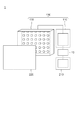
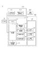
図1は、表示装置1の装置構成図である。表示装置1は、入力部10、照明装置100、液晶制御回路210および液晶パネル220を備える。照明装置100は、バックライト制御回路110およびバックライトユニット120とを備える。図2は、照明装置100を備える表示装置1の機能ブロックを示す機能ブロック図である。   FIG. 1 is a device configuration diagram of the display device 1. The display device 1 includes an input unit 10, a lighting device 100, a liquid crystal control circuit 210, and a liquid crystal panel 220. The lighting device 100 includes a backlight control circuit 110 and a backlight unit 120. FIG. 2 is a functional block diagram illustrating functional blocks of the display device 1 including the illumination device 100.

入力部10は、バックライト制御回路110と液晶制御回路210とに、制御情報を入力する。制御情報は、表示装置1が表示する画像信号や、表示装置1の最大表示輝度に関する情報である。入力部10は、制御情報を記録し、出力可能なハードディスク等の記録媒体である。なお、入力部10は、外部装置から制御情報を取得することが可能な入力端子であってもよい。   The input unit 10 inputs control information to the backlight control circuit 110 and the liquid crystal control circuit 210. The control information is information relating to the image signal displayed on the display device 1 and the maximum display luminance of the display device 1. The input unit 10 is a recording medium such as a hard disk that can record and output control information. The input unit 10 may be an input terminal that can acquire control information from an external device.

照明装置100は、液晶パネル220に光を照射するバックライト装置である。バックライト制御回路110は、バックライトユニット120の各発光ブロックの発光量を制御する制御回路である。バックライト制御回路110の動作については後述する。   The illumination device 100 is a backlight device that irradiates the liquid crystal panel 220 with light. The backlight control circuit 110 is a control circuit that controls the light emission amount of each light emission block of the backlight unit 120. The operation of the backlight control circuit 110 will be described later.

バックライトユニット120は、発光ブロック121、輝度センサ122、および温度センサ123を備える。図3は、バックライトユニット120の装置構成を示した模式図である。バックライトユニット120は、個別に輝度を制御可能な複数の発光ブロック121a〜121fを備える。発光ブロック121aは、発光ブロック121aから照射された光の輝度を検出する輝度センサ122aと、発光ブロック121aの温度を検出する温度センサ123aとを備える。また、発光ブロック121aは、複数の光源124aを備える。発光ブロック121b〜121fについてもそれぞれ対応する輝度センサ122b〜122fと、温度センサ123b〜123fと、光源124b〜124fとを備える。   The backlight unit 120 includes a light emitting block 121, a luminance sensor 122, and a temperature sensor 123. FIG. 3 is a schematic diagram showing a device configuration of the backlight unit 120. The backlight unit 120 includes a plurality of light emitting blocks 121a to 121f whose brightness can be individually controlled. The light emitting block 121a includes a luminance sensor 122a that detects the luminance of light emitted from the light emitting block 121a, and a temperature sensor 123a that detects the temperature of the light emitting block 121a. The light emitting block 121a includes a plurality of light sources 124a. The light emission blocks 121b to 121f also include corresponding luminance sensors 122b to 122f, temperature sensors 123b to 123f, and light sources 124b to 124f, respectively.

光源124は、光源124の温度によって、駆動電流に対する発光量の比率である発光効率が変化する。例えば、光源124は温度が高いほど発光効率が低くなるLED(Light Emitting Diode)であるとする。   The light emission efficiency of the light source 124, which is the ratio of the light emission amount with respect to the drive current, varies depending on the temperature of the light source 124. For example, it is assumed that the light source 124 is an LED (Light Emitting Diode) whose luminous efficiency decreases as the temperature increases.

バックライト制御回路110は、各発光ブロックの発光量を制御することが可能な制御回路基板である。バックライト制御回路110は、バックライト制御部111、経過時間取得部112、バックライト駆動部113、駆動電流取得部114、輝度取得部115、温度取得部116、およびメモリ117を備える。   The backlight control circuit 110 is a control circuit board capable of controlling the light emission amount of each light emission block. The backlight control circuit 110 includes a backlight control unit 111, an elapsed time acquisition unit 112, a backlight drive unit 113, a drive current acquisition unit 114, a luminance acquisition unit 115, a temperature acquisition unit 116, and a memory 117.

バックライト制御部111は、各発光ブロック121の駆動電流値を決定し、バックライト駆動部113に出力する演算処理装置(プロセッサ)である。なお、バックライト制御部111は、2以上のプロセッサを用いて構成されていてもよい。さらに、バックライト制御部111は、後述するバックライト制御部111が実行する機能の一部を実行可能な1以上の電子回路等のハードウェアを備えていてもよい。   The backlight control unit 111 is an arithmetic processing device (processor) that determines the drive current value of each light emitting block 121 and outputs the drive current value to the backlight drive unit 113. Note that the backlight control unit 111 may be configured using two or more processors. Furthermore, the backlight control unit 111 may include hardware such as one or more electronic circuits that can execute a part of functions executed by the backlight control unit 111 described later.

バックライト制御部111は、入力部10から取得した画像信号に基づいて、各発光ブロック121が照射する光の発光量を決定し、決定した発光量で各発光ブロック121から光が照射されるように、各発光ブロック121の駆動電流値を決定する。なお、バックライト制御部111は、表示装置1に表示される輝度の最大値の設定に応じて、各発光ブロックの発光量を決定するものであってもよい。   Based on the image signal acquired from the input unit 10, the backlight control unit 111 determines the amount of light emitted from each light-emitting block 121, and the light is emitted from each light-emitting block 121 with the determined light amount. Next, the drive current value of each light emitting block 121 is determined. Note that the backlight control unit 111 may determine the light emission amount of each light emission block in accordance with the setting of the maximum luminance value displayed on the display device 1.

バックライト制御部111は、経過時間取得部112から経過時間t1を判定パラメータとして取得し、各発光ブロック121の状態を判定する。経過時間t1の詳細については、後述する。例えば、バックライト制御部111は、判定パラメータを用いて、各発光ブロック121が、相対的に動作安定度が高い安定状態か、相対的に動作安定度が低い駆動初期状態であるかを判定するとする。前述したとおり、発光ブロックの動作安定度は、発光ブロック121の発光量の時間に対する安定性を示す指標である。   The backlight control unit 111 acquires the elapsed time t1 from the elapsed time acquisition unit 112 as a determination parameter, and determines the state of each light-emitting block 121. Details of the elapsed time t1 will be described later. For example, when the backlight control unit 111 determines whether each light-emitting block 121 is in a stable state with relatively high operation stability or a drive initial state with relatively low operation stability using the determination parameter. To do. As described above, the operational stability of the light emission block is an index indicating the stability of the light emission amount of the light emission block 121 with respect to time.

バックライト制御部111は、各発光ブロック121について個別に状態を判定することも、複数の発光ブロック121ごとに状態を判定することも可能である。例えば、バックライト制御部111は、照明装置100に含まれる全ての発光ブロック121について、状態を判定するとする。   The backlight control unit 111 can determine the state of each light emitting block 121 individually or can determine the state of each of the plurality of light emitting blocks 121. For example, it is assumed that the backlight control unit 111 determines the state of all the light emission blocks 121 included in the lighting device 100.

バックライト制御部111は、各発光ブロックの発光量を補正する処理を周期的に実行する。バックライト制御部111は、各発光ブロックの状態に基づいて、各発光ブロックに対して、輝度測定値を用いて発光量を補正する処理を実行するか、温度測定値を用いて発光量を補正する処理を実行するかを決定する。ここで、バックライト制御部111が温度測定値を用いて発光量を補正する処理を実行する周期は、輝度測定値を用いて発光量を補正する処理を実行する周期よりも長い。   The backlight control unit 111 periodically executes a process of correcting the light emission amount of each light emission block. Based on the state of each light emission block, the backlight control unit 111 executes a process for correcting the light emission amount using the luminance measurement value for each light emission block, or corrects the light emission amount using the temperature measurement value. Decide whether to execute the process. Here, the cycle in which the backlight control unit 111 executes the process of correcting the light emission amount using the temperature measurement value is longer than the cycle of executing the process of correcting the light emission amount using the brightness measurement value.

具体的には、バックライト制御部111は、発光量を補正する発光ブロック(対象発光ブロック)の動作安定度が相対的に高い状態である場合に、輝度測定値を用いて発光量を補正する。さらに、バックライト制御部111は、対象発光ブロックの動作安定度が相対的に低い状態である場合に、温度測定値を用いて発光量を補正する。   Specifically, the backlight control unit 111 corrects the light emission amount using the luminance measurement value when the operation stability of the light emission block (target light emission block) for correcting the light emission amount is relatively high. . Furthermore, the backlight control unit 111 corrects the light emission amount using the temperature measurement value when the operation stability of the target light emission block is relatively low.

バックライト制御部111が輝度測定値を用いた補正処理を実行すると決定した場合、バックライト制御部111は、輝度検出指示をバックライト駆動部113および輝度取得部115に出力する。バックライト制御部111が温度測定値を用いた補正処理を実行すると決定した場合、バックライト制御部111は、温度検出指示を温度取得部116に出力する。   When the backlight control unit 111 determines to execute the correction process using the luminance measurement value, the backlight control unit 111 outputs a luminance detection instruction to the backlight driving unit 113 and the luminance acquisition unit 115. When the backlight control unit 111 determines to execute the correction process using the temperature measurement value, the backlight control unit 111 outputs a temperature detection instruction to the temperature acquisition unit 116.

バックライト制御部111は、各発光ブロックの輝度測定値もしくは温度測定値を用いて、各発光ブロックの駆動電流値を補正して、各発光ブロックの発光量を制御する。   The backlight control unit 111 corrects the drive current value of each light emission block using the luminance measurement value or the temperature measurement value of each light emission block, and controls the light emission amount of each light emission block.

バックライト制御部111は、各発光ブロックの動作安定度の判定処理、および、駆動電流値の補正処理を含む一連の処理を、1つの補正サイクルとして周期的に実行する。照明装置100の駆動中に、バックライト制御部111は、補正サイクルを繰り返し実行する。各発光ブロックは、1つの補正サイクルの中で少なくとも1度、発光量の補正処理が実行される。   The backlight control unit 111 periodically executes a series of processes including a determination process of the operation stability of each light-emitting block and a correction process of the drive current value as one correction cycle. While the lighting apparatus 100 is being driven, the backlight control unit 111 repeatedly executes the correction cycle. Each light emission block is subjected to the light emission amount correction process at least once in one correction cycle.

バックライト制御部111が各発光ブロックに対して実行する補正サイクルの周期は、補正サイクルで、各発光ブロックに対して実行される補正処理が、輝度測定値を用いた補正処理であるか、温度測定値を用いた補正処理であるかで異なる。   The cycle of the correction cycle executed by the backlight control unit 111 for each light-emitting block is a correction cycle. Whether the correction process executed for each light-emitting block is a correction process using a luminance measurement value, or temperature It differs depending on whether the correction process uses the measured value.

経過時間取得部112は、照明装置100が駆動を開始してからの経過時間t1を計測し、バックライト制御部111に出力する。例えば、経過時間t1は、複数の発光ブロック121のうち少なくとも1つが発光を開始してからの経過時間であるとする。   The elapsed time acquisition unit 112 measures an elapsed time t1 after the lighting device 100 starts driving, and outputs the measured time to the backlight control unit 111. For example, it is assumed that the elapsed time t1 is an elapsed time after at least one of the plurality of light emitting blocks 121 starts to emit light.

バックライト駆動部113は、バックライト制御部111から取得した各発光ブロック121の駆動電流値に基づいて、各発光ブロック121の光源の発光をパルス幅変調(PWM:Pulse Width Modulation)により、制御する駆動回路である。また、バックライト駆動部113は、バックライト制御部111から輝度検出指示を取得した場合に、予め定められた測定期間において、輝度検出対象の発光ブロックを所定の駆動条件で点灯させ、かつ輝度検出対象でない発光ブロックを消灯させるように制御する。   Based on the drive current value of each light emission block 121 acquired from the backlight control unit 111, the backlight drive unit 113 controls the light emission of the light source of each light emission block 121 by pulse width modulation (PWM: Pulse Width Modulation). It is a drive circuit. In addition, when the backlight driving unit 113 acquires a luminance detection instruction from the backlight control unit 111, the backlight driving unit 113 lights the light-emitting block to be detected in a predetermined driving condition and detects the luminance during a predetermined measurement period. Control to turn off non-target light-emitting blocks.

また、バックライト駆動部113は、各発光ブロック121を駆動した場合に、各発光ブロック121に流れた駆動電流値の情報を駆動電流取得部114に出力する。   Further, when the light emitting block 121 is driven, the backlight driving unit 113 outputs information on the driving current value that has flowed to each light emitting block 121 to the driving current acquisition unit 114.

駆動電流取得部114は、バックライト駆動部113から取得した各発光ブロック121に流れた駆動電流値を取得し、バックライト制御部111に出力する電流値センサである。駆動電流取得部114は、各発光ブロック121に対して、駆動電流値の変化量を取得して、バックライト制御部111に出力することも可能である。   The drive current acquisition unit 114 is a current value sensor that acquires the drive current value that has flowed to each light emitting block 121 acquired from the backlight drive unit 113 and outputs the drive current value to the backlight control unit 111. The drive current acquisition unit 114 can also acquire the amount of change in the drive current value for each light emitting block 121 and output it to the backlight control unit 111.

輝度取得部115は、バックライト制御部111から輝度検出指示を取得した場合に、輝度測定対象の発光ブロックに対応する輝度センサ122から輝度測定値を取得する。輝度取得部115は、輝度検出対象の発光ブロックが点灯し、輝度検出対象でない発光ブロックが消灯しているタイミングで、輝度検出対象の発光ブロックに対応する輝度センサ122から出力された値を積算して、輝度検出対象の発光ブロックの輝度測定値を取得する。輝度取得部115は、取得した輝度測定値をバックライト制御部111に出力する。   When the luminance acquisition unit 115 acquires a luminance detection instruction from the backlight control unit 111, the luminance acquisition unit 115 acquires a luminance measurement value from the luminance sensor 122 corresponding to the light emission block to be measured for luminance. The luminance acquisition unit 115 integrates the values output from the luminance sensor 122 corresponding to the luminance detection target light emission block at the timing when the luminance detection target light emission block is turned on and the light emission block that is not the luminance detection target is turned off. Thus, the luminance measurement value of the light emission block to be subjected to luminance detection is acquired. The luminance acquisition unit 115 outputs the acquired luminance measurement value to the backlight control unit 111.

温度取得部116は、バックライト制御部111から温度検出指示を取得した場合に、温度測定対象の発光ブロックに対応する温度センサ123から温度測定値を取得する。温度取得部116は、取得した温度測定値をバックライト制御部111に出力する。各発光ブロック121の温度測定値は、各発光ブロック121の動作環境を示す動作情報といえる。   When the temperature acquisition unit 116 acquires a temperature detection instruction from the backlight control unit 111, the temperature acquisition unit 116 acquires a temperature measurement value from the temperature sensor 123 corresponding to the light emission block to be temperature measured. The temperature acquisition unit 116 outputs the acquired temperature measurement value to the backlight control unit 111. It can be said that the measured temperature value of each light emitting block 121 is operation information indicating the operating environment of each light emitting block 121.

メモリ117は、バックライト制御部111が用いるパラメータおよびプログラムを記憶し、バックライト制御部111が情報の読出し、および書込みが可能な記憶媒体である。メモリ117は、バックライト制御部111が各発光ブロック121の動作安定度を判定するために用いる閾値Th1、光源の発光効率と温度との関係を示す温度特性情報、および各発光ブロック121の輝度目標値を記憶し、バックライト制御部111に出力する。   The memory 117 is a storage medium in which parameters and programs used by the backlight control unit 111 are stored, and the backlight control unit 111 can read and write information. The memory 117 includes a threshold value Th <b> 1 used by the backlight control unit 111 to determine the operational stability of each light-emitting block 121, temperature characteristic information indicating the relationship between the light-emitting efficiency and temperature of the light source, and the luminance target of each light-emitting block 121. The value is stored and output to the backlight control unit 111.

液晶制御回路210は、入力部10から取得した画像信号を用いて、液晶パネル220を制御する制御回路基板である。液晶制御回路210は、画像処理部211と、液晶パネル駆動部212とを備える。   The liquid crystal control circuit 210 is a control circuit board that controls the liquid crystal panel 220 using an image signal acquired from the input unit 10. The liquid crystal control circuit 210 includes an image processing unit 211 and a liquid crystal panel driving unit 212.

画像処理部211は、入力部10から取得した画像信号に対して、γ変換処理や、シャープネス等の画像処理を施して、出力画像信号を生成する。画像処理部211は、出力画像信号を液晶パネル駆動部212に出力する。液晶パネル駆動部212は、取得した出力画像信号に基づいて、液晶パネル220の透過率を制御する。   The image processing unit 211 performs image processing such as γ conversion processing and sharpness on the image signal acquired from the input unit 10 to generate an output image signal. The image processing unit 211 outputs an output image signal to the liquid crystal panel driving unit 212. The liquid crystal panel driving unit 212 controls the transmittance of the liquid crystal panel 220 based on the acquired output image signal.

液晶パネル220は、マトリクス状に配置された複数の液晶素子と、各液晶素子に対応するカラーフィルターとを備える透過型の表示パネルである。液晶パネル駆動部212によって、出力画像信号に応じて各液晶素子の透過率が制御される。液晶パネル220は、照明装置100から照射された光を、透過して画面に画像を表示する。   The liquid crystal panel 220 is a transmissive display panel including a plurality of liquid crystal elements arranged in a matrix and a color filter corresponding to each liquid crystal element. The transmittance of each liquid crystal element is controlled by the liquid crystal panel driving unit 212 in accordance with the output image signal. The liquid crystal panel 220 transmits the light emitted from the lighting device 100 and displays an image on the screen.

なお、液晶パネル220は、透過型の表示パネルであればよく、透過率を制御する素子にMEMS(Micro Electro Mechanical Systems)素子を用いた表示パネルであってもよい。   Note that the liquid crystal panel 220 may be a transmissive display panel, and may be a display panel using a MEMS (Micro Electro Mechanical Systems) element as an element for controlling the transmittance.

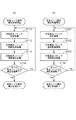
図4、および図5のフローチャートを用いて、バックライト制御部111の輝度補正処理を説明する。図4は、バックライト制御部111の輝度補正処理の1サイクルを示すフローチャートである。   The brightness correction processing of the backlight control unit 111 will be described with reference to the flowcharts of FIGS. 4 and 5. FIG. 4 is a flowchart showing one cycle of the luminance correction processing of the backlight control unit 111.

輝度補正処理のサイクルが開始されると、S100でバックライト制御部111は、経過時間取得部112から経過時間t1を取得する取得処理を実行する。処理はS101に進む。   When the brightness correction processing cycle is started, the backlight control unit 111 executes acquisition processing for acquiring the elapsed time t1 from the elapsed time acquisition unit 112 in S100. The process proceeds to S101.

S101で、バックライト制御部111は、経過時間取得部112から取得した経過時間t1を用いて、照明装置100の各発光ブロック121の状態を判定する。バックライト制御部111は、経過時間t1が閾値Th1よりも大きいか否かを判定する。具体的には、経過時間t1が所定の閾値Th1よりも大きい場合に、バックライト制御部111は、各発光ブロック121の動作安定度が相対的に高い安定状態であると判定する。さらに、経過時間t1が所定の閾値Th1以下である場合に、バックライト制御部111は、各発光ブロック121の動作安定度が相対的に低い駆動初期状態であると判定する。   In S <b> 101, the backlight control unit 111 determines the state of each light-emitting block 121 of the lighting device 100 using the elapsed time t <b> 1 acquired from the elapsed time acquisition unit 112. The backlight control unit 111 determines whether the elapsed time t1 is greater than the threshold value Th1. Specifically, when the elapsed time t1 is larger than the predetermined threshold Th1, the backlight control unit 111 determines that the operation stability of each light-emitting block 121 is relatively high. Further, when the elapsed time t1 is equal to or less than the predetermined threshold Th1, the backlight control unit 111 determines that the operation stability of each light-emitting block 121 is in a driving initial state that is relatively low.

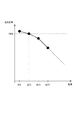
閾値Th1は、メモリ117から読み出したパラメータである。閾値Th1は、予め取得された経過時間t1に対する発光ブロック121の温度変化に基づいて、決定されたパラメータである。図6は、予め取得された経過時間t1に対する発光ブロック121の温度変化を示したグラフである。照明装置100が駆動を開始すると、バックライト制御回路110および発光ブロック121から熱が発生し、発光ブロック121の温度が上昇する。   The threshold Th1 is a parameter read from the memory 117. The threshold value Th1 is a parameter determined based on a temperature change of the light emitting block 121 with respect to the elapsed time t1 acquired in advance. FIG. 6 is a graph showing the temperature change of the light emitting block 121 with respect to the elapsed time t1 acquired in advance. When the lighting device 100 starts driving, heat is generated from the backlight control circuit 110 and the light emitting block 121, and the temperature of the light emitting block 121 rises.

例えば、閾値Th1は、発光ブロック121の温度が所定の温度閾値に到達する経過時間t1とする。図6に示すように、照明装置100の駆動を開始する前の初期温度T0が20℃であり、飽和温度Tsが50℃であるとする。温度閾値を発光ブロック121の飽和温度Tsの80%であるとすると、発光ブロック121の温度が飽和温度Tsの80%程度となる60秒を閾値Th1とする。駆動初期(経過時間t1≦Th1)では、発光ブロック121の温度変化の傾きが大きい。   For example, the threshold value Th1 is an elapsed time t1 when the temperature of the light emitting block 121 reaches a predetermined temperature threshold value. As shown in FIG. 6, it is assumed that the initial temperature T0 before starting the driving of the lighting device 100 is 20 ° C. and the saturation temperature Ts is 50 ° C. Assuming that the temperature threshold is 80% of the saturation temperature Ts of the light emitting block 121, 60 seconds when the temperature of the light emitting block 121 is about 80% of the saturation temperature Ts is set as the threshold Th1. In the initial stage of driving (elapsed time t1 ≦ Th1), the gradient of the temperature change of the light emitting block 121 is large.

なお、閾値Th1は、発光ブロック121の単位時間当たりの温度変化が所定の閾値以下となる経過時間とすることも可能である。所定の閾値は、輝度センサを用いた補正処理を実行することが可能な時間の間隔において、温度変化による発光ブロック121の発光量の変化量が、照明装置100の輝度変化として許容される値以下になる単位時間当たりの温度変化としてもよい。   Note that the threshold Th1 can also be an elapsed time during which the temperature change per unit time of the light emitting block 121 is equal to or less than a predetermined threshold. The predetermined threshold value is equal to or less than a value in which the change amount of the light emission amount of the light emission block 121 due to the temperature change is allowed as the luminance change of the lighting device 100 in the time interval in which the correction process using the luminance sensor can be executed. It may be a temperature change per unit time.

S101で、経過時間t1が閾値Th1よりも大きい場合、バックライト制御部111は、各発光ブロック121の動作安定度が相対的に高い安定状態であると判定し、S110の処理に進む。また、経過時間t1が閾値Th1以下である場合、バックライト制御部111は、各発光ブロック121の動作安定度が低い駆動初期状態にあると判定し、S120の処理に進む。   If the elapsed time t1 is greater than the threshold Th1 in S101, the backlight control unit 111 determines that the operational stability of each light-emitting block 121 is relatively high and proceeds to the processing of S110. If the elapsed time t1 is equal to or less than the threshold Th1, the backlight control unit 111 determines that the operation stability of each light-emitting block 121 is low and is in an initial driving state, and proceeds to the process of S120.

S110、もしくはS120の各補正処理を実行し、輝度補正処理の1つのサイクルが終了する。バックライト制御部111は、上述のサイクルを繰り返し実行する。   Each correction process of S110 or S120 is executed, and one cycle of the brightness correction process is completed. The backlight control unit 111 repeatedly executes the above-described cycle.

図5は、S110で実行される輝度センサ使用補正処理、およびS120で実行される温度センサ使用補正処理のフローを示したフローチャートである。図5を用いて各補正処理を説明する。   FIG. 5 is a flowchart showing a flow of the brightness sensor use correction process executed in S110 and the temperature sensor use correction process executed in S120. Each correction process will be described with reference to FIG.

図5(a)は、輝度センサ使用補正処理のフローを示すフローチャートである。S110は、各発光ブロック121に対して、対応する輝度センサ122で取得した輝度測定値に基づいて、駆動電流値を補正する処理を実行する輝度センサ使用補正処理である。   FIG. 5A is a flowchart showing a flow of luminance sensor use correction processing. S110 is luminance sensor use correction processing for executing processing for correcting the drive current value for each light emitting block 121 based on the luminance measurement value acquired by the corresponding luminance sensor 122.

輝度センサ使用補正処理が開始されると、S111で、バックライト制御部111は、補正処理を施す対象発光ブロックを決定する。例えば、対象発光ブロックは、図3で示したバックライトユニット120に含まれる複数の発光ブロック121a〜121fに対して、左上の121aから順に選択されるように決定されるとする。例えば、バックライト制御部111は、発光ブロック121aを対象発光ブロックと選択するとする。処理はS112に進む。   When the luminance sensor use correction process is started, in S111, the backlight control unit 111 determines a target light emission block to be subjected to the correction process. For example, it is assumed that the target light emission block is determined so as to be sequentially selected from the upper left 121a with respect to the plurality of light emission blocks 121a to 121f included in the backlight unit 120 illustrated in FIG. For example, it is assumed that the backlight control unit 111 selects the light emission block 121a as the target light emission block. The process proceeds to S112.

S112で、バックライト制御部111は、対象発光ブロックの輝度測定値を取得する。具体的には、バックライト駆動部113と輝度取得部115とに対して、発光ブロック121aの輝度測定値を取得する輝度取得指示を出力する。バックライト駆動部113は、発光ブロック121aを、測定期間において所定の駆動条件で点灯させ、他の発光ブロック121b〜121fを消灯するように制御する。また、輝度取得部115は、輝度センサ122aから測定期間において出力された値から発光ブロック121aの輝度測定値を取得し、バックライト制御部111に出力する。   In S112, the backlight control unit 111 acquires the luminance measurement value of the target light emission block. Specifically, a luminance acquisition instruction for acquiring a luminance measurement value of the light emission block 121a is output to the backlight driving unit 113 and the luminance acquisition unit 115. The backlight drive unit 113 controls the light emitting block 121a to be turned on under a predetermined driving condition during the measurement period, and the other light emitting blocks 121b to 121f are turned off. In addition, the luminance acquisition unit 115 acquires the luminance measurement value of the light emission block 121a from the value output from the luminance sensor 122a during the measurement period, and outputs the luminance measurement value to the backlight control unit 111.

対象発光ブロックの輝度取得処理は、対象発光ブロックの輝度を測定する際に、対象発光ブロック以外の発光ブロックの消灯を伴う。したがって、ユーザが画面を視ている場合に、発光ブロックの消灯による妨害感を感じることを抑制するために、輝度センサ使用補正処理における輝度測定処理は、一定の期間以上の期間をあけて実行されることが望ましい。例えば、輝度測定処理は4秒に1回実行されるものとする。処理はS113に進む。   The luminance acquisition process of the target light emission block involves turning off the light emission blocks other than the target light emission block when measuring the luminance of the target light emission block. Therefore, the luminance measurement processing in the luminance sensor usage correction processing is executed after a certain period of time in order to prevent the user from feeling a disturbance due to the lighting block being turned off when the user is viewing the screen. It is desirable. For example, it is assumed that the luminance measurement process is executed once every 4 seconds. The process proceeds to S113.

S113で、バックライト制御部111は、取得した発光ブロック121aの輝度測定値と、メモリ117から取得した輝度目標値とを用いて取得した発光ブロック121aの輝度変化率Rに基づいて、駆動電流値を補正する。   In S113, the backlight control unit 111 determines the drive current value based on the luminance change rate R of the light emission block 121a acquired using the acquired luminance measurement value of the light emission block 121a and the luminance target value acquired from the memory 117. Correct.

輝度目標値は、発光ブロック121aが基準状態において所定の駆動条件で駆動した場合に、輝度取得部115が取得する輝度測定値である。輝度変化率Rは、取得した輝度測定値を目標輝度値で除算した値である。つまり、輝度変化率Rは、輝度測定値を取得した時点における、基準状態からの発光ブロック121aの輝度の変化率である。基準状態は、発光ブロック121aの駆動の基準とする状態であり、例えば、発光ブロックの温度が20℃で経時劣化が小さい駆動初期における発光ブロックの状態であるとする。   The luminance target value is a luminance measurement value acquired by the luminance acquisition unit 115 when the light emitting block 121a is driven under a predetermined driving condition in the reference state. The luminance change rate R is a value obtained by dividing the acquired luminance measurement value by the target luminance value. That is, the luminance change rate R is the luminance change rate of the light emitting block 121a from the reference state at the time when the luminance measurement value is acquired. The reference state is a state used as a reference for driving the light-emitting block 121a. For example, it is assumed that the light-emitting block is in the initial driving state where the temperature of the light-emitting block is 20 ° C. and the deterioration with time is small.

バックライト制御部111は、輝度変化率Rに基づいて、駆動電流値を補正する。駆動電流値に対して発光量が線形の関係にある場合、バックライト制御部111は、発光ブロック121aの駆動電流値を輝度変化率Rで除算して補正する。例えば、バックライト制御部111が輝度測定値に基づいて、対象発光ブロックの発光量を補正する処理を実行する時間は、1秒であるとする。処理は、S114に進む。   The backlight control unit 111 corrects the drive current value based on the luminance change rate R. When the light emission amount has a linear relationship with the drive current value, the backlight control unit 111 corrects the drive current value of the light emission block 121a by dividing it by the luminance change rate R. For example, it is assumed that the time for which the backlight control unit 111 executes the process of correcting the light emission amount of the target light emission block based on the luminance measurement value is 1 second. The process proceeds to S114.

S114で、バックライト制御部111は、補正処理の対象となる全ての発光ブロックに対して補正処理が完了しているか否かを判定する。バックライト制御部111が、補正処理の対象となる全ての発光ブロックに対して補正処理が完了していないと判定した場合、処理をS111に戻す。そして、S111で、バックライト制御部111が次の発光ブロック121bを対象発光ブロックとして決定する。バックライト制御部111が、補正処理の対象となる全ての発光ブロックに対して補正処理が完了していると判定した場合、輝度センサ使用補正処理を終了する。   In step S114, the backlight control unit 111 determines whether correction processing has been completed for all light-emitting blocks that are to be corrected. When the backlight control unit 111 determines that the correction process has not been completed for all the light emission blocks to be corrected, the process returns to S111. In S111, the backlight control unit 111 determines the next light emission block 121b as the target light emission block. When the backlight control unit 111 determines that the correction process has been completed for all the light-emitting blocks that are the target of the correction process, the luminance sensor use correction process is terminated.

一連の輝度センサ使用補正処理は、対象となる全ての発光ブロック121の輝度を取得するための期間と、対象となる全ての発光ブロック121の発光量を補正するための期間との合計の期間である、輝度補正期間を必要とする。バックライト制御部111は、S101で各発光ブロック121が安定状態であると判断した場合に、輝度センサ使用補正処理を輝度補正期間以上の周期で、周期的に実行する。例えば、1つの発光ブロック121の輝度を取得するために4秒、さらに1つの発光ブロック121の発光量を補正するために1秒をそれぞれ要する場合、6個の発光ブロック121に対して輝度センサ使用補正処理を実行するため、輝度補正期間は30秒である。   A series of luminance sensor use correction processing is a total period of a period for acquiring the luminance of all the target light emitting blocks 121 and a period for correcting the light emission amounts of all the target light emitting blocks 121. A certain luminance correction period is required. When the backlight control unit 111 determines in S101 that each light-emitting block 121 is in a stable state, the backlight control unit 111 periodically executes the luminance sensor use correction process at a cycle equal to or longer than the luminance correction period. For example, when it takes 4 seconds to acquire the luminance of one light emitting block 121 and 1 second to correct the light emission amount of one light emitting block 121, a luminance sensor is used for six light emitting blocks 121. In order to execute the correction process, the luminance correction period is 30 seconds.

図5(b)は、温度センサ使用補正処理のフローを示すフローチャートである。S120は、各発光ブロック121に対して、対応する温度センサ123で取得した温度測定値に基づいて、駆動電流値を補正する処理を実行する温度センサ使用補正処理である。   FIG. 5B is a flowchart showing a flow of temperature sensor use correction processing. S120 is a temperature sensor use correction process for executing a process of correcting the drive current value based on the temperature measurement value acquired by the corresponding temperature sensor 123 for each light emitting block 121.

温度センサ使用補正処理が開始されると、S121で、バックライト制御部111は、補正処理を施す対象発光ブロックを決定する。対象発光ブロックは、S111と同様に決定されるとする。処理はS122に進む。   When the temperature sensor use correction process is started, in S121, the backlight control unit 111 determines a target light emission block to be subjected to the correction process. It is assumed that the target light emission block is determined similarly to S111. The process proceeds to S122.

S122で、バックライト制御部111は、発光ブロック121aの温度測定値を取得する。温度取得部116は、温度センサ123aから出力された値から発光ブロック121aの温度測定値を取得し、バックライト制御部111に出力する。なお、温度取得部116が、各発光ブロック121の温度測定値を取得する処理をする場合に、S112のように対象発光ブロックでない発光ブロックを消灯する処理は行われない。温度取得部116が対象発光ブロックに対して温度取得処理を実行する期間は、輝度取得部115が対象発光ブロックに対して輝度取得処理を実行する期間よりも短い。例えば、温度取得処理は、0.5秒に1回実行されるものとする。処理はS123に進む。   In S122, the backlight control unit 111 acquires a temperature measurement value of the light emission block 121a. The temperature acquisition unit 116 acquires the temperature measurement value of the light emitting block 121a from the value output from the temperature sensor 123a, and outputs it to the backlight control unit 111. In addition, when the temperature acquisition part 116 performs the process which acquires the temperature measurement value of each light emission block 121, the process which turns off the light emission block which is not an object light emission block like S112 is not performed. The period during which the temperature acquisition unit 116 executes the temperature acquisition process for the target light emission block is shorter than the period during which the luminance acquisition unit 115 executes the luminance acquisition process for the target light emission block. For example, it is assumed that the temperature acquisition process is executed once every 0.5 seconds. The process proceeds to S123.

S123で、バックライト制御部111は、取得した発光ブロック121aの温度測定値と、メモリ117から取得した発光ブロック121aの温度特性とを用いて取得した発光ブロック121aの発光効率Eaに基づいて、駆動電流値を補正する。   In S123, the backlight control unit 111 drives based on the light emission efficiency Ea of the light emission block 121a acquired using the acquired temperature measurement value of the light emission block 121a and the temperature characteristic of the light emission block 121a acquired from the memory 117. Correct the current value.

温度特性は、発光ブロック121aの温度と、発光効率Eaとの関係を示した特性である。図7は、メモリ117に記憶されている温度特性を示した模式図である。例えば、温度特性は、発光ブロック121aに対して、所定の駆動条件で駆動した場合に、複数の測定温度における発光量を測定した結果から求められる。図7に示した温度特性は、測定温度を0℃、20℃、40℃、および60℃とした場合の、発光ブロック121aの発光量から、測定温度20℃の発光量を100%として、発光効率Eaを求めた結果を示している。   The temperature characteristic is a characteristic showing the relationship between the temperature of the light emitting block 121a and the light emission efficiency Ea. FIG. 7 is a schematic diagram showing temperature characteristics stored in the memory 117. For example, the temperature characteristic is obtained from the result of measuring the light emission amounts at a plurality of measurement temperatures when the light emission block 121a is driven under a predetermined driving condition. The temperature characteristics shown in FIG. 7 indicate that light emission from the light emission block 121a when the measurement temperature is 0 ° C., 20 ° C., 40 ° C., and 60 ° C. is taken as 100%. The result which calculated | required efficiency Ea is shown.

なお、温度特性は、各発光ブロック121に対して個別に予め取得されたものであってもよい。また、各発光ブロック121に対して同一の温度特性を用いるものであってもよい。   The temperature characteristics may be acquired individually for each light emitting block 121 in advance. Further, the same temperature characteristic may be used for each light emitting block 121.

バックライト制御部111は、発光効率Eaに基づいて、駆動電流値を補正する。駆動電流値に対して発光量が線形の関係にある場合、バックライト制御部111は、発光ブロック121aの駆動電流値を発光効率Eaで除算して補正する。温度特性が図6に示したように離散的な測定温度に対して取得した発光効率Eaの測定値を示している場合、バックライト制御部111は、各測定温度以外の温度測定値に対する発光効率Eaを、各測定値を用いた線形補間によって決定する。補間の方法は、非線形補間であってもよい。例えば、バックライト制御部111が温度測定値に基づいて、対象発光ブロックの発光量を補正する処理を実行する時間は、1秒であるとする。処理は、S124に進む。   The backlight control unit 111 corrects the drive current value based on the light emission efficiency Ea. When the light emission amount has a linear relationship with the drive current value, the backlight control unit 111 corrects the drive current value of the light emission block 121a by dividing it by the light emission efficiency Ea. When the temperature characteristic indicates the measured value of the luminous efficiency Ea acquired with respect to the discrete measured temperatures as shown in FIG. 6, the backlight control unit 111 emits the luminous efficiency for the measured temperature values other than the measured temperatures. Ea is determined by linear interpolation using each measured value. The interpolation method may be nonlinear interpolation. For example, it is assumed that the time for the backlight control unit 111 to execute the process of correcting the light emission amount of the target light emission block based on the temperature measurement value is 1 second. The process proceeds to S124.

なお、温度特性から求めた発光効率Eaを用いた輝度補正は、予め測定された温度特性を用いて補正するため、誤差を含む。したがって、補正時の発光量を直接測定して補正する輝度センサ使用補正処理のほうが、温度センサ使用補正処理よりも補正の精度が高い。   Note that the luminance correction using the light emission efficiency Ea obtained from the temperature characteristics includes an error because it is corrected using the temperature characteristics measured in advance. Accordingly, the correction process using the luminance sensor that directly measures and corrects the light emission amount at the time of correction has higher correction accuracy than the correction process that uses the temperature sensor.

S124で、バックライト制御部111は、補正処理の対象となる全ての発光ブロックに対して補正処理が完了しているか否かを判定する。バックライト制御部111が、補正処理の対象となる全ての発光ブロックに対して補正処理が完了していないと判定した場合、処理をS121に戻す。そして、S121で、バックライト制御部111が次の発光ブロック121bを対象発光ブロックとして決定する。バックライト制御部111が、補正処理の対象となる全ての発光ブロックに対して補正処理が完了していると判定した場合、温度センサ使用補正処理を終了する。   In S124, the backlight control unit 111 determines whether or not the correction process has been completed for all the light-emitting blocks to be corrected. When the backlight control unit 111 determines that the correction process has not been completed for all the light-emitting blocks that are the target of the correction process, the process returns to S121. In step S121, the backlight control unit 111 determines the next light emission block 121b as the target light emission block. When the backlight control unit 111 determines that the correction process has been completed for all the light-emitting blocks that are the target of the correction process, the temperature sensor use correction process ends.

一連の温度センサ使用補正処理は、対象となる全ての発光ブロック121の温度を取得するための期間と、対象となる全ての発光ブロック121の発光量を補正するための期間との合計の期間である、温度補正期間を必要とする。バックライト制御部111は、S101で各発光ブロック121が駆動初期状態であると判断した場合に、温度センサ使用補正処理を温度補正期間以上の周期で、周期的に実行する。例えば、1つの発光ブロック121の温度を取得するために0.5秒、さらに1つの発光ブロック121の発光量を補正するために1秒をそれぞれ要する場合、6個の発光ブロック121に対して輝度センサ使用補正処理を実行するための温度補正期間は9秒である。   The series of temperature sensor use correction processing is a total period of a period for acquiring the temperatures of all target light emitting blocks 121 and a period for correcting the light emission amounts of all target light emitting blocks 121. A certain temperature correction period is required. When the backlight control unit 111 determines in S101 that each light-emitting block 121 is in the initial driving state, the backlight control unit 111 periodically executes the temperature sensor use correction process at a period equal to or higher than the temperature correction period. For example, when it takes 0.5 seconds to acquire the temperature of one light-emitting block 121 and 1 second to correct the light-emission amount of one light-emitting block 121, the luminance of the six light-emitting blocks 121 is increased. The temperature correction period for executing the sensor use correction process is 9 seconds.

温度センサ使用補正処理は、輝度センサ使用補正処理と異なり、対象発光ブロックの温度を測定する際に、対象発光ブロック以外の発光ブロックの消灯を伴う必要がない。したがって、温度センサ使用補正処理は、輝度センサ使用補正処理よりも短い期間で実行されることが可能である。バックライト制御部111は、温度センサ使用補正処理を、輝度センサ使用補正処理を実行する周期よりも短い周期で実行する。   Unlike the brightness sensor use correction process, the temperature sensor use correction process does not need to be accompanied by turning off the light emission blocks other than the target light emission block when measuring the temperature of the target light emission block. Therefore, the temperature sensor use correction process can be executed in a shorter period than the luminance sensor use correction process. The backlight control unit 111 executes the temperature sensor use correction process at a cycle shorter than the cycle at which the luminance sensor use correction process is executed.

なお、バックライト制御部111が輝度センサ使用補正処理を実行する周期、および温度センサ使用補正処理を実行する周期は、一定の周期でなくともよい。複数の輝度センサ使用補正処理が実行される間隔が輝度補正期間以上であれば、輝度センサ使用補正処理を実行する周期は、不均一な周期であってもよい。同様に、複数の温度センサ使用補正処理が実行される間隔が輝度補正期間以下であり、かつ温度補正期間以上であれば、温度センサ使用補正処理を実行する周期は、不均一な周期であってもよい。   Note that the period at which the backlight control unit 111 executes the luminance sensor use correction process and the period at which the temperature sensor use correction process is executed may not be constant. If the interval at which the plurality of brightness sensor use correction processes are executed is equal to or longer than the brightness correction period, the period for executing the brightness sensor use correction process may be a non-uniform period. Similarly, if the interval at which the plurality of temperature sensor use correction processes are executed is equal to or less than the luminance correction period and is equal to or greater than the temperature correction period, the period for executing the temperature sensor use correction process is an uneven period. Also good.

また、バックライト制御部111は、複数の温度センサ使用補正処理の間に、輝度補正期間よりも短い温度補正期間を設けることも可能である。   The backlight control unit 111 can also provide a temperature correction period shorter than the luminance correction period between the plurality of temperature sensor use correction processes.

上述の処理により、図4に示す補正サイクルにおいて、各発光ブロックに対して1度、発光量の補正処理が実行される。したがって、各発光ブロック121の発光量は、補正サイクルが実行される周期で補正される。温度センサ使用補正処理を実行する補正サイクルの周期(9秒)は、輝度センサ使用補正処理を実行する補正サイクルの周期(30秒)よりも短い。つまり、各発光ブロック121が駆動初期状態である場合に各発光ブロック121の発光量が補正される周期は、各発光ブロック121が安定状態である場合に各発光ブロック121の発光量が補正される周期よりも短い。   With the above-described processing, the light emission amount correction processing is executed once for each light emission block in the correction cycle shown in FIG. Therefore, the light emission amount of each light emission block 121 is corrected at a cycle in which the correction cycle is executed. The cycle (9 seconds) of the correction cycle for executing the temperature sensor use correction process is shorter than the cycle (30 seconds) of the correction cycle for executing the brightness sensor use correction process. That is, the period in which the light emission amount of each light emission block 121 is corrected when each light emission block 121 is in the initial driving state is the light emission amount of each light emission block 121 is corrected when each light emission block 121 is in a stable state. Shorter than the period.

次に、本実施例における輝度補正処理を実行した場合の効果について、説明する。   Next, the effect when the brightness correction process in the present embodiment is executed will be described.

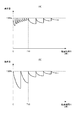
図8(a)は、本実施例における輝度補正処理を実行した場合の、経過時間t1に対する、1つの発光ブロック121(例えば121a)の発光量の変化を示したグラフである。また、図8(b)は、比較のために、輝度センサ使用補正処理のみを用いて、輝度補正処理を実行した場合の、1つの発光ブロック121(例えば121a)の発光量の経過時間t1に対する変化を示したグラフである。   FIG. 8A is a graph showing a change in the light emission amount of one light emission block 121 (for example, 121a) with respect to the elapsed time t1 when the luminance correction processing in the present embodiment is executed. FIG. 8B shows, for comparison, the elapsed time t1 of the light emission amount of one light emission block 121 (for example, 121a) when the brightness correction process is executed using only the brightness sensor use correction process. It is the graph which showed the change.

輝度補正処理を、輝度センサ使用補正処理のみで実行する場合、30秒毎に1回の補正処理が実行される。したがって、図8(b)に示すように、駆動初期において、補正処理のフィードバックがかかる間に、急激な温度変化による発光量の変化が大きくなる。   When the brightness correction process is executed only by the brightness sensor use correction process, the correction process is executed once every 30 seconds. Therefore, as shown in FIG. 8B, in the initial stage of driving, the change in the light emission amount due to the rapid temperature change becomes large while the correction process is being fed back.

本実施例における照明装置100では、各発光ブロック121の動作安定度が相対的に低い駆動初期状態である場合、温度センサ使用補正処理が実行される。例えば、温度センサ使用補正処理は、9秒の周期で実行される。したがって、図8(a)に示すように、駆動初期において、急激な温度変化による発光量の変化を小さく抑えることが可能となる。さらに、各発光ブロック121の動作安定度が相対的に高い安定状態である場合、輝度センサ使用補正処理を実行することにより、より精度の高い補正処理を実行することが可能となる。   In the lighting device 100 according to the present embodiment, when the operation stability of each light-emitting block 121 is relatively low, the temperature sensor use correction process is executed. For example, the temperature sensor use correction process is executed at a cycle of 9 seconds. Therefore, as shown in FIG. 8A, it is possible to suppress a change in the light emission amount due to a rapid temperature change in the initial stage of driving. Further, when the operational stability of each light-emitting block 121 is in a relatively high stability state, it is possible to execute a correction process with higher accuracy by executing the brightness sensor use correction process.

言い換えると、本実施例における照明装置100は、単位時間における温度変化が大きいとみなせる場合に、輝度補正に要する期間が短い補正処理を選択して実行するとも言える。   In other words, it can be said that the illumination device 100 according to the present embodiment selects and executes a correction process that requires a short period of luminance correction when it can be considered that the temperature change per unit time is large.

本発明に係る照明装置100によれば、発光ブロック121の動作安定度が相対的に低い状態である場合、温度センサ使用補正処理を用いて発光量を補正する処理を周期的に実行する。さらに、発光ブロック121の動作安定度が相対的に高い状態である場合、輝度センサ使用補正処理を用いて発光量を補正する処理を、温度センサ使用補正処理が実行される周期よりも長い周期で実行する。これにより、動作安定度が低く、発光ブロック121の時間に対する輝度変動が大きい場合に、短期間に多くの輝度補正処理を施すことが可能となる。さらに、動作安定度が高く、発光ブロック121の時間に対する輝度変動が小さい場合に、より精度の高い輝度補正処理を施すことが可能となる。したがって、照明装置の発光ブロックの動作安定度が低い場合に、発光量の変動を抑制し、好適にバックライト装置の発光量を制御することが可能となる。   According to the lighting device 100 according to the present invention, when the operational stability of the light emission block 121 is relatively low, the process of correcting the light emission amount using the temperature sensor use correction process is periodically executed. Further, when the operation stability of the light emission block 121 is relatively high, the process of correcting the light emission amount using the brightness sensor use correction process is performed at a period longer than the period at which the temperature sensor use correction process is executed. Run. Thereby, when the operational stability is low and the luminance fluctuation with respect to the time of the light emitting block 121 is large, it is possible to perform a lot of luminance correction processing in a short time. Furthermore, when the operational stability is high and the luminance variation with respect to the time of the light emitting block 121 is small, it is possible to perform a more accurate luminance correction process. Therefore, when the operation stability of the light emitting block of the lighting device is low, fluctuations in the light emission amount can be suppressed, and the light emission amount of the backlight device can be suitably controlled.

(第2の実施例)
第2の実施例に係る照明装置100は、各発光ブロック121の状態を、駆動初期状態よりも動作安定度が相対的に高く、安定状態よりも動作安定度が相対的に低い不安定状態を駆動初期状態および安定状態に加えた3段階で判定し、補正処理の内容を切り換える。そして、照明装置100の各発光ブロック121の状態が不安定状態であった場合、複数の補正処理を用いて、発光ブロック121の輝度補正処理を実行する。
(Second embodiment)
In the lighting device 100 according to the second embodiment, the state of each light-emitting block 121 is an unstable state in which the operational stability is relatively higher than the initial driving state and the operational stability is relatively lower than the stable state. The determination is made in three stages in addition to the initial driving state and the stable state, and the content of the correction process is switched. And when the state of each light emission block 121 of the illuminating device 100 is an unstable state, the brightness | luminance correction process of the light emission block 121 is performed using a some correction process.

第2の実施例に係る照明装置100の装置構成図、および機能ブロック図は、第1の実施例と同様であることから、説明を省略する。第2の実施例の照明装置100は、バックライト制御部111の輝度補正処理の一部が、第1の実施例と異なる。   Since the device configuration diagram and the functional block diagram of the illumination device 100 according to the second embodiment are the same as those in the first embodiment, description thereof will be omitted. The illumination device 100 of the second embodiment is different from the first embodiment in part of the luminance correction processing of the backlight control unit 111.

図9は、第2の実施例に係る照明装置100における輝度補正処理サイクルのフローを示したフローチャートである。輝度補正処理サイクルが開始され実行されると、S100で、バックライト制御部111は、経過時間取得部112から経過時間t1を取得する。処理はS201に進む。   FIG. 9 is a flowchart illustrating a flow of a luminance correction processing cycle in the illumination device 100 according to the second embodiment. When the luminance correction processing cycle is started and executed, the backlight control unit 111 acquires the elapsed time t1 from the elapsed time acquisition unit 112 in S100. The process proceeds to S201.

S201で、バックライト制御部111は、経過時間t1がメモリ117から取得した閾値Th2より大きいか否かを判定する。閾値Th2は、閾値Th1よりも大きい値である。例えば、閾値Th2は、発光ブロック121の温度が飽和温度Tsの95%程度となる経過時間t1に対応する値であるとする。S201で、経過時間t1が閾値Th2よりも大きい場合、バックライト制御部111は、各発光ブロック121を安定状態であると判定し、S110の処理に進む。S110は、輝度センサ使用補正処理である。輝度センサ使用補正処理は、第1の実施例で説明した同名の処理と同様であることから、説明を省略する。また、経過時間t1が閾値Th2以下である場合、S101の処理に進む。   In step S <b> 201, the backlight control unit 111 determines whether the elapsed time t <b> 1 is greater than the threshold value Th <b> 2 acquired from the memory 117. The threshold value Th2 is a value larger than the threshold value Th1. For example, the threshold value Th2 is a value corresponding to the elapsed time t1 at which the temperature of the light emitting block 121 is about 95% of the saturation temperature Ts. If the elapsed time t1 is greater than the threshold Th2 in S201, the backlight control unit 111 determines that each light-emitting block 121 is in a stable state, and proceeds to the process of S110. S110 is luminance sensor usage correction processing. The luminance sensor usage correction process is the same as the process with the same name described in the first embodiment, and thus the description thereof is omitted. If the elapsed time t1 is less than or equal to the threshold Th2, the process proceeds to S101.

S101でバックライト制御部111は、経過時間t1がメモリ117から取得した閾値Th2より大きいか否かを判定する。例えば、閾値Th1は、第1の実施例と同様の値であるとする。S101で、経過時間t1が閾値Th1よりも大きい場合、バックライト制御部111は、各発光ブロック121を、動作安定度が駆動初期状態よりも相対的に高く、かつ安定状態よりも相対的に低い不安定状態であると判定し、ハイブリッド補正処理(S130)に進む。   In S101, the backlight control unit 111 determines whether or not the elapsed time t1 is greater than the threshold value Th2 acquired from the memory 117. For example, the threshold Th1 is assumed to be the same value as in the first embodiment. In S101, when the elapsed time t1 is larger than the threshold value Th1, the backlight control unit 111 causes each light-emitting block 121 to have an operation stability relatively higher than the driving initial state and relatively lower than the stable state. It determines with it being in an unstable state, and progresses to a hybrid correction process (S130).

また、経過時間t1が閾値Th1以下である場合、バックライト制御部111は、各発光ブロック121を駆動初期状態であると判定し、S120の処理に進む。S120は、温度センサ使用補正処理である。温度センサ使用補正処理は、第1の実施例で説明した同名の処理と同様であることから、説明を省略する。   If the elapsed time t1 is equal to or less than the threshold Th1, the backlight control unit 111 determines that each light-emitting block 121 is in the initial driving state, and proceeds to the processing of S120. S120 is a temperature sensor use correction process. Since the temperature sensor use correction process is the same as the process of the same name described in the first embodiment, the description thereof is omitted.

バックライト制御部111は、経過時間t1と閾値Th1および閾値Th2とに基づいて選択した補正処理を、全ての発光ブロック121に対して実行し、輝度補正処理サイクルが終了する。バックライト制御部111は、輝度補正処理サイクルを繰り返し実行する。   The backlight control unit 111 executes the correction process selected based on the elapsed time t1, the threshold value Th1, and the threshold value Th2 for all the light-emitting blocks 121, and the luminance correction process cycle ends. The backlight control unit 111 repeatedly executes the luminance correction processing cycle.

S130は、輝度センサを用いた輝度補正処理を適用する発光ブロックと、温度センサを用いた補正処理を適用する発光ブロックとを輝度補正処理サイクル毎に切り換えるハイブリッド補正処理である。図10は、ハイブリッド補正処理のフローを示したフローチャートである。   S130 is a hybrid correction process that switches between the light emission block to which the luminance correction process using the luminance sensor is applied and the light emission block to which the correction process using the temperature sensor is applied every luminance correction processing cycle. FIG. 10 is a flowchart showing the flow of the hybrid correction process.

ハイブリッド補正処理が開始されると、バックライト制御部111は、S131で輝度センサ使用補正処理を実行する特定発光ブロックを決定する処理を実行する。バックライト制御部111は、メモリ117から、輝度補正処理サイクルに対して選択される特定発光ブロックを示す情報を取得して、特定発光ブロックを決定する。例えば、バックライト制御部111は、特定発光ブロックとして、発光ブロック121bと発光ブロック121fと決定するとする。なお、特定発光ブロックは、1つの発光ブロック121とすることも可能であるし、3つ以上の複数の発光ブロック121とすることも可能である。バックライト制御部111は、輝度補正処理サイクルごとに特定発光ブロックとして選択する発光ブロック121を切り替える。処理は、S132に進む。   When the hybrid correction process is started, the backlight control unit 111 executes a process of determining a specific light emission block for executing the luminance sensor use correction process in S131. The backlight control unit 111 acquires information indicating the specific light emission block selected for the luminance correction processing cycle from the memory 117, and determines the specific light emission block. For example, it is assumed that the backlight control unit 111 determines the light emission block 121b and the light emission block 121f as the specific light emission blocks. Note that the specific light emission block may be a single light emission block 121, or may be three or more light emission blocks 121. The backlight control unit 111 switches the light emission block 121 to be selected as the specific light emission block for each luminance correction processing cycle. The process proceeds to S132.

S132で、バックライト制御部111は、補正処理を施す対象発光ブロックを決定する。例えば、対象発光ブロックは、図3で示したバックライトユニット120に含まれる複数の発光ブロック121a〜121fに対して、左上の121aから順に選択されるように決定されるとする。例えば、バックライト制御部111は、発光ブロック121aを対象発光ブロックと選択するとする。処理はS133に進む。   In step S132, the backlight control unit 111 determines a target light emission block to be subjected to correction processing. For example, it is assumed that the target light emission block is determined so as to be sequentially selected from the upper left 121a with respect to the plurality of light emission blocks 121a to 121f included in the backlight unit 120 illustrated in FIG. For example, it is assumed that the backlight control unit 111 selects the light emission block 121a as the target light emission block. The process proceeds to S133.

S133で、バックライト制御部111は、対象発光ブロックが特定発光ブロックと同一であるか否かを判定する。対象発光ブロックが特定発光ブロックと同一である場合、処理はS134に進む。   In S133, the backlight control unit 111 determines whether or not the target light emission block is the same as the specific light emission block. If the target light emission block is the same as the specific light emission block, the process proceeds to S134.

S134で、バックライト制御部111は、対象発光ブロックの輝度測定値を取得する。S134で実行される処理は、第1の実施例におけるS112で実行される処理と同様であることから説明を省略する。S135で、バックライト制御部111は、対象発光ブロックの輝度測定値と、メモリ117から取得した輝度目標値とを用いて取得した対象発光ブロックの輝度変化率Rに基づいて、駆動電流値を補正する。S134で実行される処理は、第1の実施例におけるS113で実行される処理と同様であることから説明を省略する。処理は、S138に進む。   In S134, the backlight control unit 111 acquires the luminance measurement value of the target light emission block. Since the process executed in S134 is the same as the process executed in S112 in the first embodiment, a description thereof will be omitted. In S135, the backlight control unit 111 corrects the driving current value based on the luminance change rate R of the target light emission block acquired using the luminance measurement value of the target light emission block and the luminance target value acquired from the memory 117. To do. Since the process executed in S134 is the same as the process executed in S113 in the first embodiment, the description thereof is omitted. The process proceeds to S138.

また、S133で、バックライト制御部111が特定発光ブロックと異なる場合、処理は136に進む。   If the backlight control unit 111 is different from the specific light emission block in S133, the process proceeds to 136.

S136で、バックライト制御部111は、対象発光ブロックの温度測定値を取得する。S136で実行される処理は、第1の実施例におけるS122で実行される処理と同様であることから説明を省略する。S137で、バックライト制御部111は、取得した対象発光ブロックの温度測定値と、メモリ117から取得した対象発光ブロックの温度特性とを用いて取得した対象発光ブロックの発光効率Eaに基づいて、駆動電流値を補正する。S137で実行される処理は、第1の実施例におけるS123で実行される処理と同様であることから説明を省略する。処理は、S138に進む。   In S136, the backlight control unit 111 acquires a temperature measurement value of the target light emission block. Since the process executed in S136 is the same as the process executed in S122 in the first embodiment, the description thereof is omitted. In S137, the backlight control unit 111 performs driving based on the light emission efficiency Ea of the target light emission block acquired using the acquired temperature measurement value of the target light emission block and the temperature characteristic of the target light emission block acquired from the memory 117. Correct the current value. Since the process executed in S137 is the same as the process executed in S123 in the first embodiment, the description thereof is omitted. The process proceeds to S138.

S138で、バックライト制御部111は、補正処理の対象となる全ての発光ブロックに対して補正処理が完了しているか否かを判定する。バックライト制御部111が、補正処理の対象となる全ての発光ブロックに対して補正処理が完了していないと判定した場合、処理をS132に戻す。そして、S132で、バックライト制御部111が次の発光ブロック121を対象発光ブロックとして決定する。例えば、バックライト制御部111は、発光ブロック121bを対象発光ブロックと選択するとする。バックライト制御部111が、補正処理の対象となる全ての発光ブロックに対して補正処理が完了していると判定した場合、ハイブリッド補正処理を終了する。   In step S138, the backlight control unit 111 determines whether correction processing has been completed for all light-emitting blocks that are to be corrected. When the backlight control unit 111 determines that the correction process has not been completed for all the light emission blocks to be corrected, the process returns to S132. In step S132, the backlight control unit 111 determines the next light emission block 121 as the target light emission block. For example, it is assumed that the backlight control unit 111 selects the light emission block 121b as the target light emission block. When the backlight control unit 111 determines that the correction process has been completed for all the light-emitting blocks that are the targets of the correction process, the hybrid correction process ends.

一連のハイブリッド補正処理(S130)では、複数の発光ブロック121のうち、特定発光ブロックのみに対して輝度センサ122を用いた補正処理を実行する。従って、輝度センサ補正処理(S110)よりも、短時間に複数回の補正処理を実行することが可能となる。例えば、特定発光ブロックとして、1回の輝度補正処理サイクルに対して2つの発光ブロック121を選択するとする。   In a series of hybrid correction processes (S130), the correction process using the brightness sensor 122 is executed only for the specific light emission block among the plurality of light emission blocks 121. Therefore, the correction process can be executed a plurality of times in a shorter time than the luminance sensor correction process (S110). For example, suppose that two light emission blocks 121 are selected as a specific light emission block for one luminance correction processing cycle.

ハイブリッド補正処理は、補正の対象となる発光ブロック121のうち、特定発光ブロックに対して輝度センサ使用補正処理を施し、特定発光ブロックでない発光ブロック121に対して温度センサ使用補正処理を施す。例えば、1つの発光ブロック121に対して輝度センサ使用補正処理を施すために5秒の期間を必要とし、1つの発光ブロック121に対して温度センサ使用補正処理を施すために1.5秒の期間を必要とするとする。上述のように、2つの発光ブロック121を選択する場合、ハイブリッド補正処理を施すために必要とされる期間は、16秒の期間を要する。   In the hybrid correction process, the luminance sensor use correction process is performed on the specific light emission block among the light emission blocks 121 to be corrected, and the temperature sensor use correction process is performed on the light emission block 121 that is not the specific light emission block. For example, a period of 5 seconds is required to perform the luminance sensor use correction process on one light emitting block 121, and a period of 1.5 seconds to perform the temperature sensor use correction process on one light emitting block 121 Is required. As described above, when two light-emitting blocks 121 are selected, the period required for performing the hybrid correction process requires a period of 16 seconds.

つまり、ハイブリッド補正処理を実行するために必要とされる補正期間は、温度補正期間よりも長く、かつ輝度補正期間よりも短くなる。したがって、バックライト制御部111は、ハイブリッド補正処理を、輝度センサ使用補正処理が実行される周期よりも短く、かつ温度センサ使用補正処理が実行される周期よりも長い周期で実行する。   That is, the correction period required to execute the hybrid correction process is longer than the temperature correction period and shorter than the luminance correction period. Therefore, the backlight control unit 111 executes the hybrid correction process at a cycle shorter than the cycle at which the brightness sensor use correction process is executed and longer than the cycle at which the temperature sensor use correction process is executed.

また、バックライト制御部111は、補正サイクルごとに、特定発光ブロックを切り替えることから、各発光ブロックは、複数回の補正サイクルに対して少なくとも1回は、輝度センサを用いて輝度を補正される。したがって、補正の精度を向上させながら、短時間に複数回の補正処理を実行することが可能となる。   Further, since the backlight control unit 111 switches the specific light emission block for each correction cycle, the luminance of each light emission block is corrected using the luminance sensor at least once for a plurality of correction cycles. . Therefore, a plurality of correction processes can be executed in a short time while improving the correction accuracy.

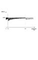
図11は、第2の実施例における輝度補正処理を実行した場合の発光量の時間変化を示した模式図である。横軸は経過時間t1を示しており、縦軸は発光量比を示している。第1の実施例と同様に、照明装置100の各発光ブロック121の動作安定度が相対的に低い駆動初期状態(t1≦Th1)において、温度センサ使用補正処理が実行される。例えば、温度センサ使用補正処理が第1の実施例と同様に9秒に1回実行されるとする。短期間に輝度補正処理を多く実行することにより、急激な温度変化による発光量の変化を、小さく抑えることが可能となる。   FIG. 11 is a schematic diagram showing a temporal change in the light emission amount when the luminance correction processing in the second embodiment is executed. The horizontal axis indicates the elapsed time t1, and the vertical axis indicates the light emission amount ratio. Similar to the first embodiment, the temperature sensor use correction process is executed in the driving initial state (t1 ≦ Th1) in which the operational stability of each light-emitting block 121 of the lighting device 100 is relatively low. For example, it is assumed that the temperature sensor use correction process is executed once every 9 seconds as in the first embodiment. By performing many brightness correction processes in a short period of time, it is possible to suppress a change in the amount of light emission due to a rapid temperature change.

さらに、照明装置100の各発光ブロック121の動作安定度が相対的に中程度である不安定状態(Th1<t1≦Th2)において、ハイブリッド補正処理が実行される。例えば、ハイブリッド補正処理は、16秒に1回実行されるとする。また、照明装置100の各発光ブロック121の動作安定度が相対的に高い安定状態(Th2<t1)において、輝度センサ使用補正処理が実行される。例えば、輝度センサ使用補正処理は、30秒に1回実行されるとする。   Further, the hybrid correction process is executed in an unstable state (Th1 <t1 ≦ Th2) in which the operational stability of each light-emitting block 121 of the lighting device 100 is relatively medium. For example, it is assumed that the hybrid correction process is executed once every 16 seconds. In addition, the luminance sensor use correction process is executed in a stable state (Th2 <t1) in which the operation stability of each light emitting block 121 of the lighting device 100 is relatively high. For example, it is assumed that the luminance sensor use correction process is executed once every 30 seconds.

バックライト制御部111は、照明装置100の各発光ブロック121の動作安定度が低いほど、各発光ブロック121に対して補正処理が実行される頻度が高くなるように、制御する。また、バックライト制御部111は、照明装置100の各発光ブロック121の動作安定度が高いほど、各発光ブロック121に対して輝度センサを用いた補正処理が実行される頻度が高くなるように、制御する。これにより、発光ブロック121の温度変化の大きさが大きいほど、補正処理の頻度が高くなり、温度変化による急激な輝度変化を補正することが可能となる。したがって、照明装置の発光ブロックの動作の安定度が変化しても、好適にバックライト装置の発光量を制御することが可能となる。   The backlight control unit 111 performs control so that the frequency with which correction processing is performed on each light-emitting block 121 increases as the operational stability of each light-emitting block 121 of the lighting device 100 decreases. In addition, the backlight control unit 111 is configured such that the higher the operational stability of each light emitting block 121 of the lighting device 100 is, the higher the frequency with which correction processing using a luminance sensor is executed on each light emitting block 121. Control. Accordingly, the greater the temperature change of the light emitting block 121, the higher the frequency of the correction process, and it is possible to correct a sudden luminance change due to the temperature change. Therefore, even if the stability of the operation of the light emitting block of the lighting device changes, the light emission amount of the backlight device can be suitably controlled.

(その他の実施例)
なお、動作安定度が低く、発光ブロック121の時間に対する輝度変動が大きい場合に、実施する補正処理は、温度センサを用いた補正処理に限らない。温度測定値以外の動作情報を用いて、輝度センサ使用補正処理も短期間に多くの補正処理を実行可能な、補正処理を実行することも可能である。
(Other examples)
Note that when the operational stability is low and the luminance variation with respect to the time of the light-emitting block 121 is large, the correction process to be performed is not limited to the correction process using the temperature sensor. Using the operation information other than the temperature measurement value, it is also possible to execute a correction process that can perform many correction processes in a short period of time using the luminance sensor correction process.

バックライト制御部111は、駆動電流取得部114が取得した各発光ブロック121に流れた駆動電流値を用いて、各発光ブロック121の輝度を補正することも可能である。光源124に流れる電流値が温度に依存する場合、駆動電流値は、温度測定値と同様に扱うことが可能となる。この場合、バックライト制御部111は、メモリ117から駆動電流値と温度と発光効率とを関連付けた情報を取得し、輝度補正処理を実行する。   The backlight control unit 111 can also correct the luminance of each light emission block 121 using the drive current value that has flowed to each light emission block 121 acquired by the drive current acquisition unit 114. When the current value flowing through the light source 124 depends on the temperature, the drive current value can be handled in the same manner as the temperature measurement value. In this case, the backlight control unit 111 acquires information that associates the drive current value, the temperature, and the light emission efficiency from the memory 117, and executes the luminance correction process.

駆動電流値を用いた補正処理は、温度センサ使用輝度補正処理と同様に、対象発光ブロック以外の発光ブロックの消灯を伴う必要がないため、短時間に多くの補正処理を実行することが可能となる。この場合、温度センサ123を設置する必要がなく、より低コストで実行することが可能となる。   Like the temperature sensor luminance correction process, the correction process using the drive current value does not need to be accompanied by turning off the light-emitting blocks other than the target light-emitting block, so that a lot of correction processes can be executed in a short time. Become. In this case, it is not necessary to install the temperature sensor 123, and it can be performed at a lower cost.

また、照明装置100の動作安定度を判定する判定パラメータは、経過時間t1以外の値を用いることも可能である。照明装置100の各発光ブロック121の制御方法が切り替わったタイミングからの経過時間t2を判定パラメータとすることも可能である。   In addition, as the determination parameter for determining the operational stability of the lighting device 100, a value other than the elapsed time t1 can be used. It is also possible to use the elapsed time t2 from the timing when the control method of each light emitting block 121 of the lighting device 100 is switched as a determination parameter.

各発光ブロック121の発光量の制御範囲の上限値が大きく変化したタイミングからの経過時間を判定パラメータとすることも可能である。例えば、表示装置1の表示モードが従来の輝度範囲(Standard Dynamic Range(SDR))で画像を表現するモードから、より高輝度の画像を表現するHigh Dynamic Range(HDR)モードに切り替わった場合、各発光ブロック121の発光量の制御範囲の上限値が大きくなる。   It is also possible to use the elapsed time from the timing when the upper limit value of the control range of the light emission amount of each light emission block 121 has changed significantly as a determination parameter. For example, when the display mode of the display device 1 is switched from a mode that expresses an image in the conventional luminance range (Standard Dynamic Range (SDR)) to a High Dynamic Range (HDR) mode that expresses a higher luminance image, The upper limit value of the light emission amount control range of the light emission block 121 is increased.

この場合、各発光ブロック121の温度は、SDRモード動作時の動作温度から、HDRモード動作時の飽和温度へ、変化する。したがって、表示モードが切り替わったタイミングからの経過時間t2を用いて、動作安定度を判定して輝度補正処理の方法を切り換えることにより、好適にバックライト装置の発光量を制御することが可能となる。なお、経過時間t2の計測タイミングは、表示装置1の表示モードが、HDRモードからSDRモードに変更したタイミングでもよい。   In this case, the temperature of each light-emitting block 121 changes from the operating temperature during the SDR mode operation to the saturation temperature during the HDR mode operation. Therefore, by using the elapsed time t2 from the timing when the display mode is switched, it is possible to suitably control the light emission amount of the backlight device by determining the operation stability and switching the luminance correction processing method. . Note that the measurement timing of the elapsed time t2 may be a timing at which the display mode of the display device 1 is changed from the HDR mode to the SDR mode.

また、各発光ブロック121を同一の発光量で制御する標準制御モードと、発光ブロック121ごとに発光量を制御するローカルディミング制御モードとを切り換えたタイミングからの経過時間t3を、判定パラメータとすることも可能である。   Also, the elapsed time t3 from the timing when the standard control mode for controlling each light emission block 121 with the same light emission amount and the local dimming control mode for controlling the light emission amount for each light emission block 121 is set as a determination parameter. Is also possible.

また、バックライト制御部111は、所定のタイミングからの経過時間以外の値を判定パラメータとして、動作安定度を判定することも可能である。例えば、バックライト制御部111は、温度センサ123が取得した発光ブロック121の単位時間あたりの温度測定値の変化が所定の閾値以上である場合に、駆動初期として判定してもよい。   The backlight control unit 111 can also determine the operational stability using a value other than the elapsed time from a predetermined timing as a determination parameter. For example, the backlight control unit 111 may determine that the driving is initial when the change in the temperature measurement value per unit time of the light emitting block 121 acquired by the temperature sensor 123 is equal to or greater than a predetermined threshold.

また、バックライト制御部111は、各発光ブロック121の駆動電流値に基づいて動作安定状態を判定することも可能である。具体的には、各発光ブロック121の駆動電流値の平均値の時間変化が、所定の値よりも大きい場合、駆動初期または不安定状態として判定する。   Further, the backlight control unit 111 can also determine the operation stable state based on the drive current value of each light emitting block 121. Specifically, when the time change of the average value of the driving current value of each light emitting block 121 is larger than a predetermined value, it is determined as the driving initial state or the unstable state.

さらに、バックライト制御部111は、発光ブロック121ごとに動作安定度を判定して、補正処理を切り換えることも可能である。この場合、対象発光ブロックが変わる毎に、バックライト制御部111は対象発光ブロックの動作安定度を判定して、補正処理の方法を切り換える。これにより、発光ブロック121ごとに、好適に輝度を補正することが可能となる。   Further, the backlight control unit 111 can determine the operational stability for each light emission block 121 and switch the correction process. In this case, every time the target light emission block changes, the backlight control unit 111 determines the operation stability of the target light emission block and switches the correction processing method. Thereby, it becomes possible to correct | amend a brightness | luminance suitably for every light emission block 121. FIG.

さらに、バックライトとして複数種類の光源、例えば3原色バックライトなどを用いることが考えられるが、光源の種類によって温度特性が異なる場合がある。このとき、光源の種類毎に、バックライト輝度の安定状態の判定条件及び補正処理を変えてもよい。   Further, it is conceivable to use a plurality of types of light sources, for example, three primary color backlights, as the backlight, but the temperature characteristics may differ depending on the type of light source. At this time, the determination condition and correction processing of the stable state of the backlight luminance may be changed for each type of light source.

100 照明装置
111 バックライト制御部
121 発光ブロック
122 輝度センサ
123 温度センサ
DESCRIPTION OF SYMBOLS 100 Illuminating device 111 Backlight control part 121 Light emission block 122 Luminance sensor 123 Temperature sensor

Claims (24)

個別に発光量を制御することが可能な複数の発光手段と、
対象発光手段を含む1または複数の発光手段について、動作安定度が相対的に低い第1の状態か、前記第1の状態よりも前記動作安定度が相対的に高い第2の状態かを判定する判定手段と、
前記対象発光手段を含む1または複数の発光手段の状態に応じて、前記対象発光手段の発光量を補正する処理を周期的に実行する補正手段と、
を備え、
前記補正手段は、前記判定手段が前記第1の状態であると判定した場合、前記対象発光手段の発光量を補正する第1補正処理を第1周期で実行し、前記判定手段が前記第2の状態であると判定した場合、前記対象発光手段の発光量を補正する第2補正処理を、前記第1周期よりも長い第2周期で実行することを特徴とする照明装置。
A plurality of light emitting means capable of individually controlling the light emission amount;
For one or more light-emitting means including the target light-emitting means, it is determined whether the first state has a relatively low operational stability or the second state has a relatively high operational stability than the first state Determination means to perform,
Correction means for periodically executing a process of correcting the light emission amount of the target light emitting means according to the state of one or a plurality of light emitting means including the target light emitting means;
With
When the determination unit determines that the determination unit is in the first state, the correction unit executes a first correction process for correcting the light emission amount of the target light emission unit in a first period, and the determination unit performs the second process. When it determines with it being a state of this, the 2nd correction process which correct | amends the light-emission quantity of the said object light emission means is performed with a 2nd period longer than the said 1st period.
前記複数の発光手段のうち、前記対象発光手段から照射された光の輝度を取得するための第1検出手段と、
前記複数の発光手段のうち、前記対象発光手段の温度を取得するための第2検出手段と、
を更に備え、
前記第1補正処理は、前記第1検出手段が取得した前記対象発光手段の輝度に基づいて、前記対象発光手段の発光量を補正する補正処理であり、
前記第2補正処理は、前記第2検出手段が取得した前記対象発光手段の温度に基づいて、前記対象発光手段の発光量を補正する補正処理である
ことを特徴とする請求項1に記載の照明装置。
Of the plurality of light emitting means, a first detecting means for obtaining the luminance of light emitted from the target light emitting means;
A second detection means for obtaining a temperature of the target light emission means among the plurality of light emission means;
Further comprising
The first correction process is a correction process for correcting the light emission amount of the target light emitting unit based on the luminance of the target light emitting unit acquired by the first detection unit;
The said 2nd correction process is a correction process which correct | amends the light emission amount of the said object light emission means based on the temperature of the said object light emission means which the said 2nd detection means acquired. Lighting device.
前記第1検出手段が前記対象発光手段の輝度を取得する場合、所定の期間において、前記複数の発光手段のうち前記対象発光手段を発光させ、かつ、前記複数の発光手段のうち他の発光手段を発光させないように制御する制御手段を更に備えることを特徴とする請求項2に記載の照明装置。   When the first detection means acquires the luminance of the target light emitting means, the target light emitting means is caused to emit light among the plurality of light emitting means and the other light emitting means among the plurality of light emitting means for a predetermined period. The lighting device according to claim 2, further comprising a control unit that controls the lamp so as not to emit light. 前記第2検出手段は、前記対象発光手段の温度を取得する温度センサであることを特徴とする請求項2または請求項3に記載の照明装置。   The lighting device according to claim 2, wherein the second detection unit is a temperature sensor that acquires a temperature of the target light emitting unit. 前記第2検出手段は、前記対象発光手段の駆動回路に流れる電流値を取得する電流値センサであることを特徴とする請求項2または請求項3に記載の照明装置。   4. The lighting device according to claim 2, wherein the second detection unit is a current value sensor that acquires a value of a current flowing through a drive circuit of the target light emitting unit. 前記判定手段は、前記対象発光手段を含む1または複数の発光手段について、前記照明装置が駆動を開始してから経過した第1の経過時間が、第1の閾値以下である場合、前記第1の状態であると判定し、前記第1の経過時間が前記第1の閾値よりも長い場合、前記第2の状態であると判定することを特徴とする請求項1乃至請求項5のいずれか1項に記載の照明装置。   When the first elapsed time that has elapsed since the lighting device has started driving is one or more light-emitting means including the target light-emitting means, the determination means is less than or equal to a first threshold value. 6. The device according to claim 1, wherein if the first elapsed time is longer than the first threshold value, the second state is determined. The lighting device according to item 1. 前記判定手段は、前記対象発光手段を含む1または複数の発光手段について、前記照明装置の駆動条件が変更されてから経過した第2の経過時間が、第2の閾値以下である場合、前記第1の状態であると判定し、前記第2の経過時間が前記第2の閾値よりも長い場合、前記第2の状態であると判定することを特徴とする請求項1乃至請求項5のいずれか1項に記載の照明装置。   When the second elapsed time that has elapsed since the driving condition of the illumination device is changed is one or more light emitting means including the target light emitting means is less than or equal to a second threshold, 6. The method according to claim 1, wherein the state is determined to be the first state, and if the second elapsed time is longer than the second threshold, the second state is determined. The lighting device according to claim 1. 各発光手段の温度変化を検出する第1取得手段を備え、
前記判定手段は、前記対象発光手段を含む1または複数の発光手段について、前記第1取得手段が取得した前記対象発光手段を含む1または複数の発光手段の温度変化が第3の閾値以上である場合、前記第1の状態であると判定し、前記温度変化が前記第3の閾値よりも小さい場合、前記第2の状態であると判定することを特徴とする請求項1乃至請求項5のいずれか1項に記載の照明装置。
Comprising first acquisition means for detecting a temperature change of each light emitting means;
For the one or more light emitting means including the target light emitting means, the determination means has a temperature change of the one or more light emitting means including the target light emitting means acquired by the first acquisition means equal to or greater than a third threshold value. The case is determined to be the first state, and when the temperature change is smaller than the third threshold, it is determined to be the second state. The lighting device according to any one of the above.
各発光手段の駆動電流の変化を検出する第2取得手段を備え、
前記判定手段は、前記対象発光手段を含む1または複数の発光手段について、前記第2取得手段が取得した前記対象発光手段の駆動電流の変化が第4の閾値以上である場合、前記第1の状態であると判定し、前記駆動電流の変化が前記第4の閾値よりも小さい場合、前記第2の状態であると判定することを特徴とする請求項1乃至請求項5のいずれか1項に記載の照明装置。
Comprising a second acquisition means for detecting a change in drive current of each light emitting means;
When the change in the drive current of the target light emitting unit acquired by the second acquisition unit is greater than or equal to a fourth threshold with respect to one or a plurality of light emitting units including the target light emitting unit, 6. The device according to claim 1, wherein the state is determined to be the second state when the change in the driving current is smaller than the fourth threshold value. The lighting device described in 1.
前記発光手段に複数種類の光源が用いられている場合に、光源の種類毎に前記判定手段の判定条件を変えることを特徴とする、請求項1乃至請求項9のいずれか1項に記載の照明装置。   10. The method according to claim 1, wherein when a plurality of types of light sources are used for the light emitting unit, the determination condition of the determination unit is changed for each type of light source. 11. Lighting device. 前記第1補正処理による発光量の補正処理は、前記第2補正処理による発光量の補正処理よりも精度が高いことを特徴とする請求項1乃至請求項10のいずれか1項に記載の照明装置。   11. The illumination according to claim 1, wherein the light emission amount correction process by the first correction process has higher accuracy than the light emission amount correction process by the second correction process. apparatus. 前記補正手段は、前記複数の発光手段について補正処理を施すサイクルを繰りかえすことを特徴とする請求項1乃至請求項11のいずれか1項に記載の照明装置。   The lighting device according to claim 1, wherein the correction unit repeats a cycle of performing correction processing on the plurality of light emitting units. 前記判定手段が、前記対象発光手段を含む1または複数の発光手段について、前記第1の状態よりも動作安定度が相対的に高く、かつ前記第2の状態よりも動作安定度が相対的に低い第3の状態と判定した場合に、前記補正手段は、第1のサイクルで前記第1補正処理で前記対象発光手段の発光量の補正処理を施し、前記第1のサイクルのあとに実行される第2のサイクルで、前記第2補正処理で前記対象発光手段の発光量の補正処理を施すことを特徴とする請求項12に記載の照明装置。   For the one or more light emitting means including the target light emitting means, the determination means has a relatively higher operational stability than the first state and a relatively higher operational stability than the second state. When it is determined that the third state is low, the correction means performs the light emission amount correction process of the target light emission means in the first correction process in the first cycle, and is executed after the first cycle. The lighting device according to claim 12, wherein in the second cycle, a correction process of the light emission amount of the target light emitting unit is performed in the second correction process. 請求項1乃至請求項13のいずれか1項に記載の前記照明装置と、
前記照明装置から照射された光を透過して画像を表示する表示手段と、
を備える表示装置。
The lighting device according to any one of claims 1 to 13,
Display means for transmitting light emitted from the illumination device and displaying an image;
A display device comprising:
個別に発光量を制御することが可能な複数の発光手段と、
各発光手段の輝度を取得する輝度取得手段と、
各発光手段の温度を取得する温度取得手段と、
対象発光手段を含む1または複数の発光手段について、動作安定度が相対的に低い第1の状態か、前記第1の状態よりも前記動作安定度が相対的に高い第2の状態かを判定する判定手段と、
前記判定手段が前記第1の状態であると判定した場合、前記対象発光手段の温度に基づいて、前記対象発光手段の発光量を補正する第1補正処理を施し、前記判定手段が前記第2の状態であると判定した場合、前記対象発光手段の輝度に基づいて前記対象発光手段の発光量に第2補正処理を施す補正手段と、
を備えることを特徴とする照明装置。
A plurality of light emitting means capable of individually controlling the light emission amount;
Luminance acquisition means for acquiring the luminance of each light emitting means;
Temperature acquisition means for acquiring the temperature of each light emitting means;
For one or more light-emitting means including the target light-emitting means, it is determined whether the first state has a relatively low operational stability or the second state has a relatively high operational stability than the first state Determination means to perform,
When it is determined that the determination unit is in the first state, a first correction process for correcting a light emission amount of the target light emitting unit is performed based on a temperature of the target light emitting unit, and the determination unit performs the second process. A correction unit that performs a second correction process on the light emission amount of the target light emitting unit based on the luminance of the target light emitting unit,
A lighting device comprising:
前記輝度取得手段が前記対象発光手段の輝度を取得する場合、所定の期間において、前記複数の発光手段のうち前記対象発光手段を発光させ、かつ、前記複数の発光手段のうち他の発光手段を発光させないように制御する制御手段を更に備えることを特徴とする請求項15に記載の照明装置。   When the luminance acquisition means acquires the luminance of the target light emitting means, the target light emitting means is caused to emit light among the plurality of light emitting means and another light emitting means is selected from among the plurality of light emitting means for a predetermined period. The illumination device according to claim 15, further comprising a control unit that performs control so as not to emit light. 前記判定手段は、前記対象発光手段を含む1または複数の発光手段について、前記照明装置が駆動を開始してから経過した第1の経過時間が、第1の閾値以下である場合、前記第1の状態であると判定し、前記第1の経過時間が前記第1の閾値よりも長い場合、前記第2の状態であると判定することを特徴とする請求項15または請求項16に記載の照明装置。   When the first elapsed time that has elapsed since the lighting device has started driving is one or more light-emitting means including the target light-emitting means, the determination means is less than or equal to a first threshold value. The state according to claim 15 is determined, and when the first elapsed time is longer than the first threshold, it is determined that the state is the second state. Lighting device. 前記判定手段は、前記対象発光手段を含む1または複数の発光手段について、前記照明装置の駆動条件が変更されてから経過した第2の経過時間が、第2の閾値以下である場合、前記第1の状態であると判定し、前記第2の経過時間が前記第2の閾値よりも長い場合、前記第2の状態であると判定することを特徴とする請求項15または請求項16に記載の照明装置。   When the second elapsed time that has elapsed since the driving condition of the illumination device is changed is one or more light emitting means including the target light emitting means is less than or equal to a second threshold, The state is determined to be 1, and if the second elapsed time is longer than the second threshold, it is determined to be the second state. Lighting equipment. 各発光手段の温度変化を検出する第1取得手段を備え、
前記判定手段は、前記対象発光手段を含む1または複数の発光手段について、前記第1取得手段が取得した前記対象発光手段を含む1または複数の発光手段の温度変化が第3の閾値以上である場合、前記第1の状態であると判定し、前記温度変化が前記第3の閾値よりも小さい場合、前記第2の状態であると判定することを特徴とする請求項15または請求項16に記載の照明装置。
Comprising first acquisition means for detecting a temperature change of each light emitting means;
For the one or more light emitting means including the target light emitting means, the determination means has a temperature change of the one or more light emitting means including the target light emitting means acquired by the first acquisition means equal to or greater than a third threshold value. The case is determined to be the first state, and when the temperature change is smaller than the third threshold, it is determined to be the second state. The lighting device described.
各発光手段の駆動電流の変化を検出する第2取得手段を備え、
前記判定手段は、前記対象発光手段を含む1または複数の発光手段について、前記第2取得手段が取得した前記対象発光手段の駆動電流の変化が第4の閾値以上である場合、前記第1の状態であると判定し、前記駆動電流の変化が前記第4の閾値よりも小さい場合、前記第2の状態であると判定することを特徴とする請求項15または請求項16に記載の照明装置。
Comprising a second acquisition means for detecting a change in drive current of each light emitting means;
When the change in the drive current of the target light emitting unit acquired by the second acquisition unit is greater than or equal to a fourth threshold with respect to one or a plurality of light emitting units including the target light emitting unit, The lighting device according to claim 15 or 16, wherein the lighting device is determined to be in the state, and when the change in the driving current is smaller than the fourth threshold value, it is determined as the second state. .
前記発光手段に複数種類の光源が用いられている場合に、光源の種類毎に前記判定手段の判定条件を変えることを特徴とする、請求項15乃至請求項20のいずれか1項に記載の照明装置。   21. The determination method according to any one of claims 15 to 20, wherein when a plurality of types of light sources are used for the light emitting unit, the determination condition of the determination unit is changed for each type of light source. Lighting device. 前記補正手段は、前記複数の発光手段について補正処理を施すサイクルを繰りかえすことを特徴とする請求項15乃至請求項21のいずれか1項に記載の照明装置。   The lighting device according to any one of claims 15 to 21, wherein the correction unit repeats a cycle of performing a correction process on the plurality of light emitting units. 前記判定手段が、前記対象発光手段を含む1または複数の発光手段について、前記第1の状態よりも動作安定度が相対的に高く、かつ前記第2の状態よりも動作安定度が相対的に低い第3の状態と判定した場合に、前記補正手段は、第1のサイクルで前記第1補正処理で前記対象発光手段の発光量の補正処理を施し、前記第1のサイクルのあとに実行される第2のサイクルで、前記第2補正処理で前記対象発光手段の発光量の補正処理を施すことを特徴とする請求項22に記載の照明装置。   For the one or more light emitting means including the target light emitting means, the determination means has a relatively higher operational stability than the first state and a relatively higher operational stability than the second state. When it is determined that the third state is low, the correction means performs the light emission amount correction process of the target light emission means in the first correction process in the first cycle, and is executed after the first cycle. 23. The lighting device according to claim 22, wherein in the second cycle, the light emission amount correction process of the target light emitting unit is performed in the second correction process. 請求項15乃至請求項23のいずれか1項に記載の前記照明装置と、
前記照明装置から照射された光を透過して画像を表示する表示手段と、
を備える表示装置。
The lighting device according to any one of claims 15 to 23;
Display means for transmitting light emitted from the illumination device and displaying an image;
A display device comprising:
JP2016094173A 2016-05-09 2016-05-09 Illuminating device, and display device using the same Pending JP2017204341A (en)

Priority Applications (1)

Application Number Priority Date Filing Date Title
JP2016094173A JP2017204341A (en) 2016-05-09 2016-05-09 Illuminating device, and display device using the same

Applications Claiming Priority (1)

Application Number Priority Date Filing Date Title
JP2016094173A JP2017204341A (en) 2016-05-09 2016-05-09 Illuminating device, and display device using the same

Publications (1)

Publication Number Publication Date
JP2017204341A true JP2017204341A (en) 2017-11-16

Family

ID=60322410

Family Applications (1)

Application Number Title Priority Date Filing Date
JP2016094173A Pending JP2017204341A (en) 2016-05-09 2016-05-09 Illuminating device, and display device using the same

Country Status (1)

Country Link
JP (1) JP2017204341A (en)

Cited By (3)

* Cited by examiner, † Cited by third party
Publication number Priority date Publication date Assignee Title
CN113063120A (en) * 2021-04-22 2021-07-02 深圳科宏健半导体照明有限公司 Integrated explosion-proof LED industrial lighting device
CN113611242A (en) * 2021-07-30 2021-11-05 卡莱特云科技股份有限公司 LED screen correction coefficient generation method, LED screen correction coefficient adjustment method and LED screen correction system
JP2022088040A (en) * 2020-12-02 2022-06-14 カシオ計算機株式会社 Projection device, method for controlling projection device and program

Cited By (4)

* Cited by examiner, † Cited by third party
Publication number Priority date Publication date Assignee Title
JP2022088040A (en) * 2020-12-02 2022-06-14 カシオ計算機株式会社 Projection device, method for controlling projection device and program
JP7219867B2 (en) 2020-12-02 2023-02-09 カシオ計算機株式会社 PROJECTION DEVICE, TEMPERATURE CONTROL METHOD FOR PROJECTION DEVICE, AND PROGRAM
CN113063120A (en) * 2021-04-22 2021-07-02 深圳科宏健半导体照明有限公司 Integrated explosion-proof LED industrial lighting device
CN113611242A (en) * 2021-07-30 2021-11-05 卡莱特云科技股份有限公司 LED screen correction coefficient generation method, LED screen correction coefficient adjustment method and LED screen correction system

Similar Documents

Publication Publication Date Title
JP5984398B2 (en) Light emitting device and control method thereof
KR101614662B1 (en) Projection apparatus and projection method
US8829798B2 (en) Light amount control apparatus, control method therefor, and display apparatus
US9262968B2 (en) Image display apparatus and control method thereof
JP6120552B2 (en) Display device and control method thereof
JP2011523759A (en) Apparatus and method for controlling the color point of an LED light source
JP2008102404A (en) Display device
CN106448544B (en) LED display
RU2012103548A (en) LIQUID CRYSTAL DISPLAY DEVICE AND METHOD OF CONTROL THE LIGHT SOURCE
US9851628B2 (en) Light source control apparatus, image projection apparatus and storage medium storing light source control program
JP2017003699A5 (en)
JP2013033215A (en) Backlight device, control method for the same, and image display device
JP2007095391A (en) Led light source device
JP2017204341A (en) Illuminating device, and display device using the same
JP5766040B2 (en) LIGHT EMITTING DEVICE, ITS CONTROL METHOD, AND IMAGE DISPLAY DEVICE
JP2007096113A (en) Led light source device
JP2015079732A (en) Light source device, control method for light source device, and program
JP5297986B2 (en) Light source driving method and display device using the same
JP6312406B2 (en) LIGHT SOURCE DEVICE, LIGHT SOURCE DEVICE CONTROL METHOD, AND PROGRAM
US10219352B2 (en) Light-emitting apparatus and display apparatus
JP6594086B2 (en) LED display device
JP6288972B2 (en) Image display apparatus and control method thereof
JP2008210887A (en) Led control system
JP2017032890A (en) LED display device
JP2009021529A (en) Lighting device and method of controlling lighting device