JP6739151B2 - LED display device - Google Patents
LED display device Download PDFInfo
- Publication number
- JP6739151B2 JP6739151B2 JP2015154712A JP2015154712A JP6739151B2 JP 6739151 B2 JP6739151 B2 JP 6739151B2 JP 2015154712 A JP2015154712 A JP 2015154712A JP 2015154712 A JP2015154712 A JP 2015154712A JP 6739151 B2 JP6739151 B2 JP 6739151B2
- Authority
- JP
- Japan
- Prior art keywords
- brightness
- led
- lighting time
- leds
- unit
- Prior art date
- Legal status (The legal status is an assumption and is not a legal conclusion. Google has not performed a legal analysis and makes no representation as to the accuracy of the status listed.)
- Active
Links
Images


Description
本発明は、LED(Light Emitting Diode:発光ダイオード)を有するLED表示部を備えるLED表示装置に関する。 The present invention relates to an LED display device including an LED display unit having an LED (Light Emitting Diode).
LEDを有するLED表示装置は、LEDの技術発展と低コスト化により、屋外及び屋内の広告表示等の多くの用途に使用されている。具体的には、従来、LED表示装置は、自然画及びアニメーションの動画像の表示に主に使用されていた。しかし近年、画素ピッチの狭ピッチ化に伴い、視認距離が短くても画質を維持することが可能となったことから、屋内での用途として、会議室や監視用途などにも使用されている。 LED display devices having LEDs have been used for many applications such as outdoor and indoor advertisement displays due to technological development and cost reduction of LEDs. Specifically, conventionally, the LED display device has been mainly used for displaying a natural image and a moving image of animation. However, in recent years, as the pixel pitch has become narrower, it has become possible to maintain image quality even when the viewing distance is short, and therefore, it is also used as an indoor application such as a conference room or a monitoring application.
このうち監視用途においては、静止画に近いパソコン画像を表示することが多い。しかしながら、LEDは点灯時間が長くなるにつれて輝度が低下するため、画像の内容により各LEDの点灯時間、ひいては各LEDの輝度低下率が異なる。この結果、点灯時間に伴う画素の輝度ばらつき及び色ばらつきが発生していた。 Of these, personal computer images that are close to still images are often displayed for monitoring purposes. However, since the brightness of the LED decreases as the lighting time increases, the lighting time of each LED, and thus the brightness reduction rate of each LED, varies depending on the content of the image. As a result, variations in luminance and colors of pixels occur with the lighting time.
このような輝度ばらつき及び色ばらつきを低減するために、LED表示部の輝度を検出して当該輝度を補正する技術、または、LEDの表示時間を積算し、当該積算によって得られる積算時間に基づいて輝度補正係数を補正することにより輝度を補正する技術が提案されている(例えば特許文献1及び2)。 In order to reduce such brightness variations and color variations, a technique of detecting the brightness of the LED display unit and correcting the brightness, or integrating the display time of the LED and based on the integration time obtained by the integration Techniques for correcting the brightness by correcting the brightness correction coefficient have been proposed (for example, Patent Documents 1 and 2).
寿命試験などにより積算時間に基づいてLEDの輝度低下率を計測し、当該輝度低下率を用いて輝度を補正する技術によれば、LEDの点灯時間の違いに起因する輝度ばらつき及び色ばらつきを補正することは可能である。しかしながら、LEDの製造ロットの違いによる特性のばらつきなどのように、予測困難な特性のばらつきが必然的に存在する。このため、単純に積算時間に基づいて、精度よく輝度ばらつきを補正することは困難であった。 According to the technology of measuring the brightness reduction rate of the LED based on the integrated time by a life test and correcting the brightness using the brightness reduction rate, the brightness variation and the color variation due to the difference in the lighting time of the LED are corrected. It is possible to do so. However, there are inevitably variations in characteristics that are difficult to predict, such as variations in characteristics due to differences in LED manufacturing lots. Therefore, it is difficult to accurately correct the luminance variation based on the integrated time.
また、所望の画像を表示するLED表示部から輝度を検出する技術では、精度よく輝度を補正することが可能であるが、輝度検出時に輝度検出用の画像を表示する必要がある。このため、24時間稼働が求められる表示システム(例えば上述の監視用途の表示システムなど)においては、輝度ばらつき等を補正するために表示(稼動)を停止するか、表示を維持するために輝度ばらつき等の補正を断念するかのいずれかを甘受せねばならなかった。 Further, with the technique of detecting the brightness from the LED display unit that displays a desired image, the brightness can be corrected with high accuracy, but it is necessary to display the brightness detection image at the time of detecting the brightness. Therefore, in a display system that requires 24-hour operation (for example, the above-described display system for monitoring purposes), the display (operation) is stopped to correct the brightness variation or the like, or the brightness variation is maintained to maintain the display. I had to accept either of the abandoned corrections.
そこで、本発明は、上記のような問題点を鑑みてなされたものであり、第1LED表示部にて所望の画像を表示させたまま、第1LED表示部の輝度ばらつき及び色ばらつきを抑制可能な技術を提供することを目的とする。 Therefore, the present invention has been made in view of the above problems, and it is possible to suppress the luminance variation and the color variation of the first LED display unit while the desired image is displayed on the first LED display unit. The purpose is to provide technology.
本発明に係るLED表示装置は、第1LEDを有する第1LED表示部と、前記第1LEDと輝度の推移が同等である複数組の第2LEDを有する第2LED表示部と、前記第1LEDの第1累積点灯時間を記憶する点灯時間記憶部と、前記複数組の第2LEDの輝度を測定する輝度測定部と、前記輝度測定部で測定された前記複数組の第2LEDの前記輝度の推移と、前記複数組の第2LEDの第2累積点灯時間とを対応付けて随時記憶する輝度推移記憶部と、前記点灯時間記憶部に記憶された前記第1累積点灯時間と、前記輝度推移記憶部に随時記憶された前記複数組の第2LEDの前記輝度の推移及び前記第2累積点灯時間とに基づいて、前記第1LEDの輝度を補正する輝度補正部とを備える。前記第1LEDは、赤色、緑色及び青色のLEDを含み、前記複数組の第2LEDのそれぞれは、赤色、緑色及び青色のLEDを含み、前記第1LED及び前記複数組の第2LEDのそれぞれは、PWM信号によって駆動され、前記点灯時間記憶部は、前記第1LED及び前記複数組の第2LEDのデューティ比に基づいて、前記第1累積点灯時間及び前記第2累積点灯時間を記憶し、前記輝度補正部で用いられる前記第2累積点灯時間の長さを、複数の前記第1累積点灯時間のうち最も長い第1累積点灯時間の長さに制御し、前記輝度補正部は、前記点灯時間記憶部に記憶された複数の前記第1累積点灯時間のうち最も長い第1累積点灯時間と、前記輝度推移記憶部に随時記憶された前記複数組の第2LEDの前記輝度の推移及び前記第2累積点灯時間の回帰分析とに基づいて、前記第1LED表示部の全てのLEDの輝度を最も輝度が低下した前記第1LEDの輝度に統一するよう補正を行い、前記全てのLEDの輝度のばらつき及び色ばらつきを抑制する。
An LED display device according to the present invention includes a first LED display unit having a first LED, a second LED display unit having a plurality of sets of second LEDs having the same luminance transition as the first LED, and a first accumulation of the first LEDs. A lighting time storage unit that stores a lighting time, a brightness measurement unit that measures the brightness of the plurality of sets of second LEDs, a transition of the brightness of the plurality of sets of second LEDs measured by the brightness measurement unit, and a plurality of the brightness measurement units. a luminance transition storage unit that stores any time in association with the second accumulated lighting time of the set of first 2LED, and the lighting time storage unit the first cumulative lighting time stored in, is from time to time stored in the luminance transition storage unit And a brightness correction unit that corrects the brightness of the first LED based on the transition of the brightness of the plurality of sets of the second LEDs and the second cumulative lighting time. The first LED includes red, green and blue LEDs, each of the plurality of sets of second LEDs includes red, green and blue LEDs, and each of the first LED and the plurality of sets of second LEDs is PWM. Driven by a signal, the lighting time storage unit stores the first cumulative lighting time and the second cumulative lighting time based on the duty ratio of the first LED and the plurality of sets of second LEDs, and the brightness correction unit. Control the length of the second cumulative lighting time used in, to the length of the longest first cumulative lighting time of the plurality of the first cumulative lighting time, the brightness correction unit, the lighting time storage unit The longest first cumulative lighting time among the plurality of stored first cumulative lighting times, the transition of the brightness of the plurality of sets of the second LEDs stored at any time in the brightness transition storage unit, and the second cumulative lighting time. Based on the regression analysis of 1., the brightness of all the LEDs of the first LED display unit is corrected to be the same as the brightness of the first LED with the lowest brightness, and the brightness variations and color variations of all the LEDs are corrected. Suppress.
本発明によれば、点灯時間記憶部に記憶された第1累積点灯時間と、輝度推移記憶部に記憶された第2LEDの輝度の推移及び第2累積点灯時間とに基づいて、第1LED表示部の第1LEDの輝度を補正する。これにより、第1LED表示部にて所望の画像を表示させたまま、第1LED表示部の輝度ばらつき及び色ばらつきを抑制することができる。 According to the present invention, the first LED display unit is based on the first cumulative lighting time stored in the lighting time storage unit, the brightness transition of the second LED and the second cumulative lighting time stored in the brightness transition storage unit. The brightness of the first LED of is corrected. As a result, it is possible to suppress luminance variations and color variations of the first LED display unit while the desired image is displayed on the first LED display unit.
<実施の形態1>
図1は、本発明の実施の形態1に係るLED表示装置の構成を示すブロック図である。図1(a)のLED表示装置100は、第1LED表示部1と、第2LED表示部2と、入力端子3と、映像信号処理部4と、信号補正部5と、第1駆動部6と、点灯時間記憶部7と、信号生成部8と、第2駆動部9と、輝度測定部10と、輝度推移記憶部である輝度低下率記憶部11と、補正係数演算部12とを備える。なお、輝度補正部18は、信号補正部5及び補正係数演算部12を含んでいる。
<Embodiment 1>
FIG. 1 is a block diagram showing the configuration of the LED display device according to the first embodiment of the present invention. The
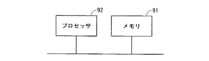
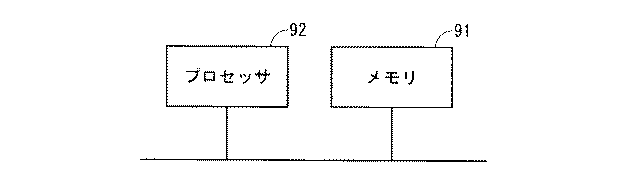
まず各構成要素のハードウェアについて説明する。第1LED表示部1、及び、第2LED表示部2には、例えばLED表示パネルが適用され、輝度測定部10には、例えば可視域の波長で計測可能なフォトダイオードなどの計測デバイスが適用される。点灯時間記憶部7及び輝度低下率記憶部11には、例えば図2のメモリ91が適用される。映像信号処理部4、信号補正部5、第1駆動部6、信号生成部8、第2駆動部9、及び、補正係数演算部12(以下「映像信号処理部4等」と記す)は、例えば図2のプロセッサ92が、メモリ91に記憶されたプログラムを実行することによって実現される。
First, the hardware of each component will be described. For example, an LED display panel is applied to the first LED display unit 1 and the second LED display unit 2, and a measurement device such as a photodiode capable of measuring at a wavelength in the visible range is applied to the
なお、メモリ91は、例えば、RAM、ROM、フラッシュメモリー、EPROM、EEPROM等の、不揮発性または揮発性の半導体メモリや、磁気ディスク、フレキシブルディスク、光ディスク、コンパクトディスク、ミニディスク、DVD等を含む。プロセッサ92は、例えば、CPU(Central Processing Unit)、中央処理装置、処理装置、演算装置、マイクロプロセッサ、マイクロコンピュータ、プロセッサ、DSPを含む。上記プログラムは、映像信号処理部4等の手順や方法をコンピュータに実行させるものであり、例えば、ソフトウェア、ファームウェア、またはソフトウェアとファームウェアとの組み合わせにより実現される。
The
なお、映像信号処理部4等は、ソフトウェアプログラムに従って動作することにより実現される構成に限ったものではなく、例えば、当該動作をハードウェアの電気回路で実現する信号処理回路であってもよい。または、映像信号処理部4等は、ソフトウェアプログラムにより実現される構成と、ハードウェアにより実現される構成との組み合わせであってもよい。 The video signal processing unit 4 and the like are not limited to the configuration realized by operating according to the software program, and may be, for example, a signal processing circuit realizing the operation by an electric circuit of hardware. Alternatively, the video signal processing unit 4 and the like may be a combination of a configuration realized by a software program and a configuration realized by hardware.
次に、図1のLED表示装置100の各構成要素について概要を説明した後、いくつかの構成要素について詳細に説明する。
Next, an outline of each component of the
<概要>
第1LED表示部1は、例えば文字、図形などの所望の画像を表示するために用いられる。第1LED表示部1は、複数の第1LED1aを有しており、第1駆動部6からの第1駆動信号(換言すれば表示パターン、駆動パターン、駆動データ)に基づいて駆動されることによって、個々の第1LED1aの点灯制御などが行われる。
<Overview>
The 1st LED display part 1 is used in order to display a desired image, such as a character and a figure, for example. The first LED display unit 1 has a plurality of first LEDs 1a, and is driven based on a first drive signal (in other words, display pattern, drive pattern, drive data) from the first drive unit 6, Lighting control of the individual first LEDs 1a and the like are performed.
第1LED1aは、赤色(R)、緑色(G)及び青色(B)のいずれかのLEDを含んでおり、第1LED表示部1が有する複数の第1LED1aは、R、G及びBのLEDを含んでいる。なお、図1(a)の例では、縦4組×横4組の合計16組の第1LED1aが、マトリクス状に配設されている。そして、1組の第1LED1aは、図1(b)に示すように、R、G及びBの合計3つのLEDを含んでいる。ただし、第1LED1aの数はこれに限ったものではない。 The first LED 1a includes any one of red (R), green (G), and blue (B) LEDs, and the plurality of first LEDs 1a included in the first LED display unit 1 include R, G, and B LEDs. I'm out. In addition, in the example of FIG. 1A, a total of 16 sets of the first LEDs 1a of 4 sets in the vertical direction×4 sets in the horizontal direction are arranged in a matrix. Then, one set of the first LEDs 1a includes a total of three LEDs of R, G and B, as shown in FIG. 1(b). However, the number of the first LEDs 1a is not limited to this.
第2LED表示部2は、第1LED表示部1の輝度の推移を計測(予測)するための表示を行う。なお、輝度の推移は、例えば初期輝度を100%として現在の輝度を示す輝度の維持率、または、輝度の維持率と逆の関係である輝度の低下率(=100%−輝度の維持率)などを含む。以下では、輝度の推移に、輝度の低下率が適用されているものとして説明する。 The second LED display unit 2 performs a display for measuring (predicting) the transition of the brightness of the first LED display unit 1. Note that the transition of the luminance is, for example, the luminance maintenance rate indicating the current luminance with the initial luminance being 100%, or the luminance reduction rate (=100%−luminance maintenance rate) which is the inverse relationship to the luminance maintenance rate. Including etc. In the following description, it is assumed that the luminance decrease rate is applied to the luminance transition.
第2LED表示部2は、複数の第2LED2aを有しており、第2駆動部9からの第2駆動信号(換言すれば表示パターン、駆動パターン、駆動データ)に基づいて駆動されることによって、個々の第2LED2aの点灯制御などが行われる。
The second LED display unit 2 has a plurality of
ここで、第2LED2aの輝度低下率と、第1LED1aと輝度低下率とは同等である。つまり、第2LED2aの輝度低下率が、第1LED1aの輝度低下率と同一、または同一視できる程度に類似している。例えば、第1LED1a及び第2LED2aに、製造ロットが同じLEDが適用されたり、輝度及び波長などによりLEDを分類するBINコードが同じLEDが適用されたりすると、両者の輝度及び波長などの特性が合わされるので、両者の輝度低下率が同等となる。
Here, the luminance reduction rate of the
第2LED2aは、第1LED1aと同様に、R、G及びBのいずれかのLEDを含んでおり、第2LED表示部2が有する複数の第2LED2aは、R、G及びBのLEDを含んでいる。なお、図1(a)の例では、縦2組×横2組の合計4組の第2LED2aが、マトリクス状に配設されている。そして、1組の第2LED2aは、1組の第1LED1aと同様に、R、G及びBの合計3つのLEDを含んでいる。ただし、第2LED2aの数はこれに限ったものではない。
The
加えて本実施の形態1では、第1LED表示部1の表示(駆動)と、第2LED表示部2の表示(駆動)とが並行して行われる。これにより、第1LED1a及び第2LED2aが、同じような環境下で点灯されるので、両者の輝度低下率を互いに近づけることが可能となっている。
In addition, in the first embodiment, the display (drive) of the first LED display unit 1 and the display (drive) of the second LED display unit 2 are performed in parallel. As a result, the first LED 1a and the
入力端子3は、外部から映像信号を受け付ける。映像信号処理部4は、入力端子3で受け付けた映像信号に基づいて、表示に必要な領域を選択したり、ガンマ補正などの処理を行ったりする。
The
信号補正部5は、後述する補正係数演算部12からの補正係数を用いて、映像信号処理部4の出力信号の輝度を補正する。この補正により、信号補正部5は、第1駆動部6から第1LED表示部1への第1駆動信号、ひいては1以上の第1LED1aの輝度を、実質的に補正することが可能となっている。
The
第1駆動部6は、信号補正部5で補正された出力信号に基づいて、第1LED表示部1を駆動するための第1駆動信号を生成する。第1駆動部6は、当該第1駆動信号を第1LED表示部1に出力することによって、第1LED表示部1を駆動する。
The first drive unit 6 generates a first drive signal for driving the first LED display unit 1 based on the output signal corrected by the
点灯時間記憶部7は、第1LED1aの第1累積点灯時間(第1LED1aが点灯された時間を累積的に加算することにより得られる時間)を記憶する。
The lighting
信号生成部8は、信号補正部5で補正された出力信号に基づいて、第2LED表示部2の第2駆動信号を生成するための信号を生成する。
The signal generation unit 8 generates a signal for generating the second drive signal of the second LED display unit 2 based on the output signal corrected by the
第2駆動部9は、信号生成部8で生成された信号に基づいて、第2LED表示部2を駆動するための第2駆動信号を生成する。第2駆動部9は、当該第2駆動信号を第2LED表示部2に出力することによって、第2LED表示部2を駆動する。
The
輝度測定部10は、第2LED表示部2の第2LED2aの輝度を測定する。
The
輝度推移記憶部である輝度低下率記憶部11は、輝度測定部10で測定された第2LED2aの輝度の低下率と、第2LED2aの第2累積点灯時間(第2LED2aが点灯された時間を累積的に加算することにより得られる時間)とを対応付けて記憶する。なお、輝度測定部10の測定、及び、輝度低下率記憶部11の記憶は、第2LED表示部2が表示されている間、随時行われる。
The brightness reduction
補正係数演算部12は、点灯時間記憶部7に記憶された第1累積点灯時間と、輝度低下率記憶部11に記憶された第2LED2aの輝度低下率及び第2累積点灯時間とに基づいて、輝度の補正係数を算出する。
The correction
ここで図1の輝度補正部18は、上述した信号補正部5及び補正係数演算部12を含んでいる。このため、輝度補正部18は、点灯時間記憶部7に記憶された第1累積点灯時間と、輝度低下率記憶部11に記憶された第2LED2aの輝度低下率及び第2累積点灯時間とに基づいて上述した補正係数を算出する。そして、輝度補正部18は、当該補正係数を用いて、映像信号処理部4の出力信号の輝度を補正することによって、第1駆動部6の第1駆動信号(駆動信号)、ひいては第1LED1aの輝度を補正する。
Here, the
なお、本実施の形態1では、複数の第1LED1aの複数の第1累積点灯時間は異なっている。そして、輝度補正部18は、点灯時間記憶部7に記憶された複数の第1累積点灯時間のうち最も長い第1累積点灯時間と、輝度低下率記憶部11に記憶された第2LED2aの輝度低下率及び第2累積点灯時間とに基づいて上記補正を行うように構成されている。
In the first embodiment, the plurality of first cumulative lighting times of the plurality of first LEDs 1a are different. Then, the
<詳細>
本実施の形態1では、第1駆動部6の第1駆動信号のデューティ比の情報が、信号補正部5で補正された出力信号に含まれる。点灯時間記憶部7は、当該出力信号に含まれるデューティ比に基づいて、個々の第1LED1aの点灯時間を一定の単位時間ごとに累積することにより、個々の第1LED1aの第1累積点灯時間を記憶する。例えば、単位時間が1時間であり、かつ、デューティ比が10%の輝度の点灯である場合には、1時間ごとに0.1時間の点灯時間(点滅時間から消灯時間を除いた時間)が、点灯時間記憶部7の第1累積点灯時間に加算されることになる。
<Details>
In the first embodiment, information on the duty ratio of the first drive signal of the first drive unit 6 is included in the output signal corrected by the
図3は、緑色(G)の第1LED1aの輝度低下率と点灯時間(第1累積点灯時間)との関係の一例を示す図である。なお、図3の点灯時間の目盛には対数目盛が適用されている。 FIG. 3 is a diagram showing an example of the relationship between the luminance reduction rate of the green (G) first LED 1a and the lighting time (first cumulative lighting time). A logarithmic scale is applied to the lighting time scale in FIG.
図3に示されるように、点灯時間の増加とともに、緑色(G)の第1LED1aの輝度低下率は大きくなり、緑色(G)の第1LED1aの輝度は低下する。程度には差があるが、赤色(R)及び青色(B)の第1LED1aの輝度も、点灯時間の増加とともに低下する(図示せず)。また後述するように、第2LED2aの輝度も、点灯時間の増加とともに低下する。
As shown in FIG. 3, as the lighting time increases, the brightness reduction rate of the green (G) first LED 1a increases, and the brightness of the green (G) first LED 1a decreases. Although there is a difference in degree, the brightness of the red (R) and blue (B) first LEDs 1a also decreases as the lighting time increases (not shown). Further, as will be described later, the brightness of the
従来技術では、第1LED1aの輝度低下率は、事前に輝度を実測することによって求められる。これに対して、本実施の形態1では、第1LED1aの輝度を実測するのではなく、第1点灯時間を実測し、当該第1点灯時間と実質的に同じ第2点灯時間に対応付けられた第2LED2aの輝度低下率を、第1LED1aの輝度低下率として計測(予測)するように構成されている。以下、第1LED1aの輝度低下率の計測(予測)について説明する。
In the related art, the brightness reduction rate of the first LED 1a is obtained by measuring the brightness in advance. On the other hand, in the first embodiment, the brightness of the first LED 1a is not actually measured, but the first lighting time is actually measured and associated with the second lighting time substantially the same as the first lighting time. The luminance reduction rate of the
信号生成部8は、信号補正部5で補正された出力信号に基づいて、第2LED表示部2の表示を制御するための第2駆動信号となる信号を生成する。第2駆動部9は、信号生成部8で生成された信号に基づいて、第2LED表示部2を駆動する。
The signal generation unit 8 generates a signal that is a second drive signal for controlling the display of the second LED display unit 2 based on the output signal corrected by the
ここで、信号生成部8は、信号補正部5で補正された出力信号から、第1LED表示部1の第1駆動信号(例えばPWM(Pulse Width Modulation)信号)の最大デューティ比を読み取り、当該最大デューティ比で第2LED表示部2を駆動するための信号を生成する。これにより、第1LED表示部1の第1駆動信号の最大デューティ比が100%であれば、第2LED表示部2の第2駆動信号のデューティ比も100%に設定される。
Here, the signal generation unit 8 reads the maximum duty ratio of the first drive signal (for example, a PWM (Pulse Width Modulation) signal) of the first LED display unit 1 from the output signal corrected by the
この結果、本実施の形態1では、第2LED2aの第2累積点灯時間は、第1LED表示部1が有する複数の第1LED1aの第1累積点灯時間の中で最も長い第1累積点灯時間に設定される。つまり、第2LED2aの第2累積点灯時間の長さが、第1LED1aの第1累積点灯時間の長さ以上となるように制御される。なお、この制御は、R,G,Bごとに行われてもよい。
As a result, in the first embodiment, the second cumulative lighting time of the
輝度測定部10は、第2LED表示部2と対向配置されており、第2LED2aの輝度を測定する。実施の形態1では、輝度測定部10は、個々の第2LED2aの各色の輝度を測定する。
The
図4は、R、G及びBの第2LED2aの輝度低下率と経過時間である点灯時間(第2累積点灯時間)との関係の一例を示す図である。なお、図4の点灯時間の目盛には対数目盛が適用されている。
FIG. 4 is a diagram showing an example of the relationship between the luminance reduction rate of the R, G and B
図4に示されるように、第2LED2aの輝度も、第1LED1aの輝度と同様に点灯時間とともに低下する。ここでR,G,Bの第2LED2aの輝度低下率は、点灯時間tの関数kr(t),kg(t),kb(t)によってそれぞれ示すことが可能である。この関数kr(t),kg(t),kb(t)は、輝度低下率記憶部11に記憶された複数組の第2LED2aの輝度低下率及び第2累積点灯時間に回帰分析などを行なうことによって、近似式または補間式などの関係式として算出可能である。
As shown in FIG. 4, the brightness of the
輝度低下率記憶部11には、輝度測定部10の測定結果と、第2LED2aの点灯時間とが対応付けられて記憶される。そして、輝度補正部18が、点灯時間記憶部7に記憶された第1LED1aの点灯時間(実測時間)と同じまたはそれに近い第2LED2aの点灯時間に対応する輝度(輝度低下率)を読み取る。これにより本実施の形態1では、第1LED1aの輝度を実測しなくても、第1LED1aの輝度低下率を実質的に計測することが可能となっている。
The measurement result of the
<動作>
図5は、本実施の形態1に係るLED表示装置100の輝度補正の動作を示すフローチャートである。
<Operation>
FIG. 5 is a flowchart showing the operation of the brightness correction of the
まずステップS1にて、輝度補正部18(信号補正部5及び補正係数演算部12)は、動作開始時から、または前回の補正時から現時点までの時間が、輝度補正の単位時間(例えば100時間)を超えたか否かを判定する。ここで、輝度補正の単位時間は、一定時間であってもよいし、補正回数に応じて変化する時間(例えば補正回数の指数関数として示される時間)であってもよい。輝度補正の単位時間を経過したと判定した場合にはステップS2に進み、そうでない場合にはステップS1を再度行う。
First, in step S1, the brightness correction unit 18 (the
ステップS2にて、輝度補正部18は、点灯時間記憶部7を参照し、R,G,Bの第1LED1aの最大累積点灯時間trmax,tgmax,tbmaxを検索する。
In step S2, the
ステップS3にて、輝度補正部18は、ステップS2で検索した最大累積点灯時間trmax,tgmax,tbmaxと同じまたはそれに近い第2累積点灯時間に対応するR,G,Bの輝度低下率を、輝度低下率記憶部11から取得する。ここで取得されるR,G,Bの輝度低下率は、上述した輝度低下率の関数kr(t),kg(t),kb(t)のtに、trmax,tgmax,tbmaxをそれぞれ適用したkr(trmax),kg(tgmax),kb(tbmax)とほぼ同じである。そこで、以下の説明では便宜上、ステップS3で取得したR,G,Bの輝度低下率を、輝度低下率kr(trmax),kg(tgmax),kb(tbmax)と記すこともある。
In step S3, the
輝度補正部18は、輝度低下率kr(trmax),kg(tgmax),kb(tbmax)のうち、最も大きい輝度低下率を、最大輝度低下率krgb(tmax)として求める。つまり、輝度補正部18は、次式(1)で示される最大輝度低下率krgb(tmax)を求める。
The
ステップS4にて、輝度補正部18は、点灯時間記憶部7及び輝度低下率記憶部11を参照し、第1LED表示部1の全ての第1LED1aについて、累積点灯時間tに対する理論上の輝度低下率と、ステップS3で求めた最大輝度低下率krgb(tmax)とに基づいて、各第1LED1aに対する補正係数を求める。
In step S4, the
ここで、R,G,Bの第1LED1aの現在の理論上の輝度をRp,Gp,Bpとし、累積点灯時間tにおけるR,G,Bの第1LED1aの理論上の輝度低下率をkr(t),kg(t),kb(t)とし、最大輝度低下率をkrgb(tmax)とすると、補正後のR,G,Bの第1LED1aの輝度Rcomp,Gcomp,Bcompは、次式(2)で示される。なお、累積点灯時間tにおけるR,G,Bの輝度低下率kr(t),kg(t),kb(t)には、例えば前回の補正において求めた最大輝度低下率が適用される。 Here, the current theoretical brightness of the R, G, B first LEDs 1a is Rp, Gp, Bp, and the theoretical brightness reduction rate of the R, G, B first LEDs 1a at the cumulative lighting time t is kr(t. ), kg(t), kb(t), and the maximum luminance reduction rate is krgb(tmax), the corrected luminances Rcomp, Gcomp, and Bcomp of the R, G, and B first LEDs 1a are expressed by the following equation (2). Indicated by. Note that the maximum luminance reduction rate obtained in the previous correction is applied to the R, G, and B luminance reduction rates kr(t), kg(t), and kb(t) at the cumulative lighting time t.
本実施の形態1に係る輝度補正部18は、上式(2)の右辺の式からRp,Gp,Bpを除いた式を、ステップS4で求めるべき補正係数の式として用いる。
The
なお、上式(2)における現在の理論上の輝度Rp,Gp,Bpは、R,G,Bの第1LED1aの初期輝度をR0,G0,B0とすると、次式(3)で示される。 The current theoretical brightness Rp, Gp, Bp in the above expression (2) is expressed by the following expression (3), where the initial brightness of the R, G, B first LEDs 1a is R0, G0, B0.
上式(3)を上式(2)に代入すれば、補正後のR,G,Bの第1LED1aの輝度Rcomp,Gcomp,Bcompは、次式(4)で示される。次式(4)で示されるように、輝度Rcomp,Gcomp,Bcompは、R,G,Bの第1LED1aの初期輝度R0,G0,B0を、最大輝度低下率krgb(tmax)によって統一的に補正したものとなる。 Substituting the above equation (3) into the above equation (2), the corrected brightness Rcomp, Gcomp, Bcomp of the R, G, B first LEDs 1a is given by the following equation (4). As shown in the following expression (4), the brightnesses Rcomp, Gcomp, and Bcomp are unified to correct the initial brightnesses R0, G0, and B0 of the R, G, and B first LEDs 1a by the maximum brightness reduction rate krgb(tmax). It will be what you did.
ステップS4の後、ステップS5にて、輝度補正部18は、ステップS4で求めた補正係数を用いて、映像信号処理部4の出力信号の輝度を、実質的には第1駆動信号を補正することによって、第1LED1aの輝度を補正する。その後、ステップS1に戻る。
After step S4, in step S5, the
ここで第1LED1aの輝度調整には、例えばPWM方式などが適用される。図6は、PWM方式で用いられるPWM駆動の一例を示す図である。図6(a)には、PWMの基本周期(パルス周期)が示されており、映像信号の1フレーム期間以下の期間が、PWMの基本周期に適用される。図6(b)には、パルス幅のデューティ比が例えば85%の場合が示され、図6(c)には、パルス幅のデューティ比が例えば80%の場合が示されている。パルス周期は非常に短いので、パルス周期のLEDの点滅は、人の目には点灯として感じられる。このようなPWM方式では、デューティ比が小さいほどLEDの点灯時間の割合が小さいので、人の目が感じる輝度は、図6(b)の場合よりも図6(c)の場合の方が低くなる。このように、パルス幅のデューティ比を変更することによって、第1LED1aの輝度を調整することが可能となる。 Here, for example, a PWM method is applied to the brightness adjustment of the first LED 1a. FIG. 6 is a diagram showing an example of PWM drive used in the PWM method. FIG. 6A shows a PWM basic cycle (pulse cycle), and a period of one frame period or less of the video signal is applied to the PWM basic cycle. FIG. 6B shows the case where the duty ratio of the pulse width is, for example, 85%, and FIG. 6C shows the case where the duty ratio of the pulse width is, for example, 80%. Since the pulse cycle is very short, blinking of the LED of the pulse cycle is perceived as lighting by human eyes. In such a PWM method, the smaller the duty ratio is, the smaller the proportion of the lighting time of the LED is, and thus the luminance perceived by human eyes is lower in the case of FIG. 6C than in the case of FIG. 6B. Become. As described above, by changing the duty ratio of the pulse width, it becomes possible to adjust the brightness of the first LED 1a.
上述のステップS5では、輝度調整と同様にパルス幅のデューティ比を変更することによって輝度の補正が行われる。例えば、krgb(tmax)=0.2、kr(t)=0.1の場合、補正係数の式(上式(2)の右辺の式からRp,Gp,Bpを除いた式)により、輝度Rpに対する補正係数は(1−0.2)/(1−0.1)=8/9となる。このため、輝度補正部18は、PWMのデューティ比を8/9倍することにより、第1LED1aの補正を行う。
In step S5 described above, the brightness is corrected by changing the duty ratio of the pulse width as in the brightness adjustment. For example, when krgb(tmax)=0.2 and kr(t)=0.1, the brightness is calculated by the correction coefficient formula (the formula on the right side of the above formula (2) excluding Rp, Gp, and Bp). The correction coefficient for Rp is (1-0.2)/(1-0.1)=8/9. Therefore, the
<実施の形態1のまとめ>
以上のような補正を行う本実施の形態1に係るLED表示装置100によれば、第1LED表示部1の補正後の輝度は、補正前の輝度と比べて全体的に低下するが、全ての第1LED1aの輝度を、点灯時間が最も長いLEDの輝度(輝度低下率が最も大きい輝度)に統一することができる。このため、第1LED表示部1全体として輝度の均一性、ホワイトバランスを保つことができ、輝度ばらつき及び色ばらつきを抑制することができる。
<Summary of First Embodiment>
According to the
また本実施の形態1では、第2LED表示部2は、第1LED表示部1の最大デューティ比で駆動している。これにより、第2LED2aの第2累積点灯時間の長さが、第1LED1aの第1累積点灯時間の長さ以上となるので、第2LED2aの輝度低下が、第1LED1aの輝度低下と同じかそれよりも早くなる。このことは、輝度低下率記憶部11には、点灯時間が最も長い第2LED2aの輝度低下率が、第1LED1aの将来の輝度低下率として記憶されることを意味する。本実施の形態1では、輝度低下率記憶部11に記憶されている第2LED2aの輝度低下率に基づいて、第1LED1aの輝度低下率を予測するので、第1LED1aの輝度低下率の予測精度、ひいては輝度補正の精度を高めることができる。
In addition, in the first embodiment, the second LED display unit 2 is driven at the maximum duty ratio of the first LED display unit 1. As a result, the length of the second cumulative lighting time of the
従来技術では、第1LED表示部1において所望の画像を継続して表示させたまま、第1LED表示部1の輝度低下率を測定することができず、輝度ばらつき及び色ばらつきを抑制することができなかった。これに対して本実施の形態1では、第1LED表示部1にて所望の画像を表示させたまま、第1LED表示部1とは別の第2LED表示部2の輝度低下率を実測することによって、第1LED表示部1の輝度低下率を実質的に測定することができるので、輝度ばらつき及び色ばらつきを抑制することができる。この結果、新しいLEDモジュールへの交換の低減化も期待できる。 In the conventional technology, the luminance reduction rate of the first LED display unit 1 cannot be measured while the desired image is continuously displayed on the first LED display unit 1, and the luminance variation and the color variation can be suppressed. There wasn't. On the other hand, in the first embodiment, the luminance reduction rate of the second LED display unit 2 different from the first LED display unit 1 is actually measured while the desired image is displayed on the first LED display unit 1. Since the luminance reduction rate of the first LED display unit 1 can be substantially measured, it is possible to suppress luminance variation and color variation. As a result, it is possible to expect a reduction in replacement with a new LED module.
<変形例>
実施の形態1では、第2LED表示部2は、複数組(図1では縦2組×横2組の合計4組)の第2LED2aから構成されていた。しかし、第2LED表示部2は、必ずしも複数組から構成される必要はなく、1組の第2LED2aから構成されてもよい。ただし、複数組の第2LED2aからなる構成は、1組の第2LED2aからなる構成に比べて、各色の輝度の平均値を用いることができるので、個々の輝度のばらつきによる悪影響を抑制することができる。
<Modification>
In the first embodiment, the second LED display unit 2 is composed of a plurality of sets (two sets in the vertical direction×two sets in the horizontal direction, a total of four sets) of the
また、実施の形態1では、輝度補正部18が、点灯時間記憶部7に記憶された第1LED1aの点灯時間(実測時間)と同じまたはそれに近い第2LED2aの点灯時間に対応する輝度を読み取ることによって、第1LED1aの輝度低下率を計測(予測)するように構成されていた。
In the first embodiment, the
このような構成の代わりに、輝度補正部18は、輝度低下率記憶部11に記憶された複数組の第2LED2aの輝度低下率及び第2累積点灯時間に回帰分析などを行なうことによって、輝度低下率の関数kr(t),kg(t),kb(t)を算出してもよい。そして、輝度補正部18は、輝度低下率の関数kr(t),kg(t),kb(t)のtに、第1LED1aについて最大累積点灯時間trmax,tgmax,tbmaxをそれぞれ適用したkr(trmax),kg(tgmax),kb(tbmax)を、第1LED1aの輝度低下率として計測(予測)してもよい。
Instead of such a configuration, the
このような構成によれば、第2LED2aの第2累積点灯時間の長さが、第1LED1aの第1累積点灯時間の長さ以上となるように制御されなくても、第1LED1aの輝度低下率を予測することができる。
According to such a configuration, even if the length of the second cumulative lighting time of the
なお、以上の変形例は、後述する実施の形態2においても適用可能である。 Note that the above modified example can also be applied to the second embodiment described later.
<実施の形態2>
本発明の実施の形態2に係るLED表示装置のブロック構成は、実施の形態1に係るLED表示装置のブロック構成(図1)と同じである。以下、本実施の形態2に係るLED表示装置のうち、実施の形態1と同じまたは類似する構成要素については同じ参照符号を付し、異なる構成要素について主に説明する。
<Second Embodiment>
The block configuration of the LED display device according to the second embodiment of the present invention is the same as the block configuration (FIG. 1) of the LED display device according to the first embodiment. Hereinafter, in the LED display device according to the second embodiment, the same or similar components as those in the first embodiment are designated by the same reference numerals, and different components will be mainly described.
実施の形態1に係るLED表示装置100は、例えば第1LED1aの初期輝度に最大輝度を用いる場合を想定して、第1LED表示部1の各第1LED1aの輝度低下率のうち最も大きい輝度低下率に統一するように輝度補正を行った。
In the
これに対して本実施の形態2に係るLED表示装置100は、第1LED1aの最大輝度よりも小さい輝度(例えば最大輝度の50%の輝度)を、第1LED1aの初期輝度に用いる。このような構成によれば、輝度補正部18は、第1LED表示部1の各第1LED1aの輝度低下率のうち、最も小さい輝度低下率に統一するように輝度補正を行うことができる。このため、輝度補正部18は、補正によって、第1LED1aの輝度を、一定の初期輝度に調整(維持)することが可能となっている。
On the other hand, the
具体的には、R,G,Bの第1LED1aの現在の理論上の輝度をRp,Gp,Bpとし、累積点灯時間tにおけるR,G,Bの理論上の輝度低下率をkr(t),kg(t),kb(t)とすると、補正後のR,G,Bの第1LED1aの輝度Rcomp,Gcomp,Bcompは、次式(5)で示される。 Specifically, the current theoretical brightness of the R, G, B first LEDs 1a is Rp, Gp, Bp, and the theoretical brightness reduction rate of R, G, B at the cumulative lighting time t is kr(t). , Kg(t), kb(t), the corrected brightnesses Rcomp, Gcomp, Bcomp of the R, G, B first LEDs 1a are expressed by the following equation (5).
上式(3)を上式(5)に代入すると、補正後のR,G,Bの第1LED1aの輝度Rcomp,Gcomp,Bcompは、次式(6)で示される。次式(6)で示されるように、補正後のR,G,Bの第1LED1aの輝度Rcomp,Gcomp,Bcompは、R,G,Bの第1LED1aの初期輝度R0,G0,B0に補正されることになる。 Substituting the above equation (3) into the above equation (5), the corrected brightness Rcomp, Gcomp, Bcomp of the R, G, B first LEDs 1a is shown by the following equation (6). As shown in the following equation (6), the corrected brightnesses Rcomp, Gcomp, Bcomp of the R, G, B first LEDs 1a are corrected to the initial brightnesses R0, G0, B0 of the R, G, B first LEDs 1a. Will be.
<実施の形態2のまとめ>
本実施の形態2によれば、初期輝度は低くなるものの、補正前後でも輝度を一定に保つことができる利点がある。第1LED1aの輝度の補正は、実施の形態1と同様にパルス幅のデューティ比を変化させることで行うことが可能である。以上のように、輝度が低下した第1LED1aの輝度が、初期輝度になるように補正することで、全ての第1LED1aの輝度を初期輝度に合わせることが可能となり、経時変化により第1LED1aの輝度が低下しても、第1LED表示部1の輝度均一性を保つことが可能となる。
<Summary of Second Embodiment>
According to the second embodiment, although the initial luminance is low, there is an advantage that the luminance can be kept constant before and after the correction. The brightness of the first LED 1a can be corrected by changing the duty ratio of the pulse width as in the first embodiment. As described above, by correcting the brightness of the first LED 1a whose brightness has decreased to the initial brightness, it is possible to match the brightness of all the first LEDs 1a to the initial brightness, and the brightness of the first LED 1a changes with time. Even if it decreases, it becomes possible to maintain the brightness uniformity of the first LED display unit 1.
なお、輝度を一定に維持可能な上述の制御を、複数のLEDパネルによってマルチ画面表示が可能な構成に対して適用すれば、各LEDパネルの輝度を同様に一定に保つことができる。したがって、上述と同様に、マルチ画面表示全体の輝度を均一に保つことができる。 If the above-described control capable of maintaining the brightness constant is applied to a configuration capable of performing multi-screen display by a plurality of LED panels, the brightness of each LED panel can be maintained constant similarly. Therefore, similar to the above, the brightness of the entire multi-screen display can be kept uniform.
また以上の説明では、第1LED1aの輝度補正を、映像信号処理部4の出力に対して行った。しかし、処理結果として、第1LED1aの第1駆動信号のデューティ比、駆動電流、または、第1LED表示部1の駆動が補正されればよく、輝度補正の対象は、映像信号処理部4の出力に限定されるものではない。 In the above description, the brightness correction of the first LED 1a is performed on the output of the video signal processing unit 4. However, as the processing result, the duty ratio of the first drive signal of the first LED 1a, the drive current, or the drive of the first LED display unit 1 may be corrected, and the target of the brightness correction is the output of the video signal processing unit 4. It is not limited.
なお、本発明は、その発明の範囲内において、各実施の形態及び各変形例を自由に組み合わせたり、各実施の形態及び各変形例を適宜、変形、省略したりすることが可能である。 It should be noted that, within the scope of the invention, the present invention can freely combine each embodiment and each modification, and appropriately change or omit each embodiment and each modification.
1 第1LED表示部、1a 第1LED、2 第2LED表示部、2a 第2LED、7 点灯時間記憶部、10 輝度測定部、11 輝度低下率記憶部、18 輝度補正部、100 LED表示装置。 1 1st LED display part, 1a 1st LED, 2 2nd LED display part, 2a 2nd LED, 7 lighting time storage part, 10 brightness|luminance measurement part, 11 brightness|luminance fall rate storage part, 18 brightness|luminance correction|amendment part, 100 LED display device.
Claims (5)
前記第1LEDと輝度の推移が同等である複数組の第2LEDを有する第2LED表示部と、
前記第1LEDの第1累積点灯時間を記憶する点灯時間記憶部と、
前記複数組の第2LEDの輝度を測定する輝度測定部と、
前記輝度測定部で測定された前記複数組の第2LEDの前記輝度の推移と、前記複数組の第2LEDの第2累積点灯時間とを対応付けて随時記憶する輝度推移記憶部と、
前記点灯時間記憶部に記憶された前記第1累積点灯時間と、前記輝度推移記憶部に随時記憶された前記複数組の第2LEDの前記輝度の推移及び前記第2累積点灯時間とに基づいて、前記第1LEDの輝度を補正する輝度補正部と
を備え、
前記第1LEDは、赤色、緑色及び青色のLEDを含み、
前記複数組の第2LEDのそれぞれは、赤色、緑色及び青色のLEDを含み、
前記第1LED及び前記複数組の第2LEDのそれぞれは、PWM信号によって駆動され、
前記点灯時間記憶部は、
前記第1LED及び前記複数組の第2LEDのデューティ比に基づいて、前記第1累積点灯時間及び前記第2累積点灯時間を記憶し、
前記輝度補正部で用いられる前記第2累積点灯時間の長さを、複数の前記第1累積点灯時間のうち最も長い第1累積点灯時間の長さに制御し、
前記輝度補正部は、
前記点灯時間記憶部に記憶された複数の前記第1累積点灯時間のうち最も長い第1累積点灯時間と、前記輝度推移記憶部に随時記憶された前記複数組の第2LEDの前記輝度の推移及び前記第2累積点灯時間の回帰分析とに基づいて、前記第1LED表示部の全てのLEDの輝度を最も輝度が低下した前記第1LEDの輝度に統一するよう補正を行い、前記全てのLEDの輝度のばらつき及び色ばらつきを抑制する、LED表示装置。 A first LED display section having a first LED;
A second LED display section having a plurality of sets of second LEDs having the same transition of brightness as the first LED;
A lighting time storage unit that stores a first cumulative lighting time of the first LED;
A brightness measurement unit that measures the brightness of the plurality of sets of second LEDs;
A luminance transition storage unit that stores the transition of the luminance of the plurality of sets of the second LEDs measured by the luminance measurement unit and the second accumulated lighting time of the plurality of sets of the second LEDs in association with each other at any time ,
Based on the first cumulative lighting time stored in the lighting time storage unit, the brightness transitions of the plurality of sets of the second LEDs and the second cumulative lighting time stored in the brightness transition storage unit at any time , A brightness correction unit that corrects the brightness of the first LED,
The first LED includes red, green and blue LEDs,
Each of the plurality of sets of second LEDs includes red, green and blue LEDs,
Each of the first LED and the plurality of second LEDs is driven by a PWM signal,
The lighting time storage unit,
Storing the first cumulative lighting time and the second cumulative lighting time based on the duty ratios of the first LED and the plurality of sets of second LEDs;
The length of the second cumulative lighting time used in the brightness correction unit is controlled to be the longest length of the first cumulative lighting time of the plurality of the first cumulative lighting times,
The brightness correction unit,
The longest first cumulative lighting time among the plurality of first cumulative lighting times stored in the lighting time storage unit, and the transition of the brightness of the plurality of sets of second LEDs stored in the brightness transition storage unit at any time, and Based on the regression analysis of the second cumulative lighting time, the luminance of all the LEDs of the first LED display unit is corrected to be the luminance of the first LED with the lowest luminance, and the luminance of all the LEDs is corrected. LED display device which suppresses the variation in color and the variation in color.
最も輝度が低下した前記第1LEDの輝度は、前記第1累積点灯時間が最も長い前記第1LEDの輝度である、LED表示装置。 The LED display device according to claim 1, wherein
The LED display device in which the brightness of the first LED having the lowest brightness is the brightness of the first LED having the longest first cumulative lighting time.
前記輝度補正部は、
前記補正によって、前記第1LEDの輝度を初期輝度に調整する、LED表示装置。 The LED display device according to claim 1 or 2, wherein
The brightness correction unit,
The LED display device adjusts the brightness of the first LED to an initial brightness by the correction.
前記第1LED表示部の表示と、前記第2LED表示部の表示とが並行して行われる、LED表示装置。 The LED display device according to any one of claims 1 to 3,
An LED display device in which the display of the first LED display unit and the display of the second LED display unit are performed in parallel.
前記第1LED表示部は、駆動信号に基づいて駆動され、
前記輝度補正部は、
前記点灯時間記憶部に記憶された前記第1累積点灯時間と、前記輝度推移記憶部に記憶された前記第2LEDの前記輝度の推移及び前記第2累積点灯時間とに基づいて補正係数を算出し、当該補正係数を用いて前記駆動信号を補正することによって、前記第1LEDの輝度を補正する、LED表示装置。 The LED display device according to any one of claims 1 to 4,
The first LED display unit is driven based on a drive signal,
The brightness correction unit,
A correction coefficient is calculated based on the first cumulative lighting time stored in the lighting time storage unit, the brightness transition of the second LED stored in the brightness transition storage unit, and the second cumulative lighting time. An LED display device that corrects the brightness of the first LED by correcting the drive signal using the correction coefficient.
Priority Applications (4)
| Application Number | Priority Date | Filing Date | Title |
|---|---|---|---|
| JP2015154712A JP6739151B2 (en) | 2015-08-05 | 2015-08-05 | LED display device |
| US15/204,835 US9591720B2 (en) | 2015-08-05 | 2016-07-07 | LED display apparatus |
| CN201610584586.XA CN106448544B (en) | 2015-08-05 | 2016-07-22 | LED display |
| RU2016132139A RU2636803C1 (en) | 2015-08-05 | 2016-08-04 | Device for led display elements |
Applications Claiming Priority (1)
| Application Number | Priority Date | Filing Date | Title |
|---|---|---|---|
| JP2015154712A JP6739151B2 (en) | 2015-08-05 | 2015-08-05 | LED display device |
Publications (2)
| Publication Number | Publication Date |
|---|---|
| JP2017032890A JP2017032890A (en) | 2017-02-09 |
| JP6739151B2 true JP6739151B2 (en) | 2020-08-12 |
Family
ID=57988042
Family Applications (1)
| Application Number | Title | Priority Date | Filing Date |
|---|---|---|---|
| JP2015154712A Active JP6739151B2 (en) | 2015-08-05 | 2015-08-05 | LED display device |
Country Status (1)
| Country | Link |
|---|---|
| JP (1) | JP6739151B2 (en) |
Families Citing this family (3)
| Publication number | Priority date | Publication date | Assignee | Title |
|---|---|---|---|---|
| JPWO2019092774A1 (en) * | 2017-11-07 | 2019-11-14 | 三菱電機株式会社 | Display system, display device, and display control device |
| CN112368761A (en) * | 2018-07-05 | 2021-02-12 | 三菱电机株式会社 | LED display system, LED display device and LED display control device |
| WO2022074784A1 (en) * | 2020-10-08 | 2022-04-14 | 三菱電機株式会社 | Led display system |
Family Cites Families (3)
| Publication number | Priority date | Publication date | Assignee | Title |
|---|---|---|---|---|
| EP1879169A1 (en) * | 2006-07-14 | 2008-01-16 | Barco N.V. | Aging compensation for display boards comprising light emitting elements |
| JP2008122516A (en) * | 2006-11-09 | 2008-05-29 | Matsushita Electric Ind Co Ltd | Display device and video signal processing system |
| KR100902219B1 (en) * | 2007-12-05 | 2009-06-11 | 삼성모바일디스플레이주식회사 | Organic Light Emitting Display |
-
2015
- 2015-08-05 JP JP2015154712A patent/JP6739151B2/en active Active
Also Published As
| Publication number | Publication date |
|---|---|
| JP2017032890A (en) | 2017-02-09 |
Similar Documents
| Publication | Publication Date | Title |
|---|---|---|
| WO2017061195A1 (en) | Light-emitting diode display device | |
| JP6437123B2 (en) | LED display device and brightness correction method thereof | |
| US9591720B2 (en) | LED display apparatus | |
| CN106169283B (en) | LED display and image display | |
| US20190088193A1 (en) | Display apparatus and control method therefor | |
| JP6827594B2 (en) | LED display system and LED display control device | |
| RU2012107427A (en) | IMAGE DISPLAY DEVICE AND METHOD FOR DISPLAYING IMAGES | |
| JP6594086B2 (en) | LED display device | |
| JP6818944B2 (en) | Display device | |
| RU2014139709A (en) | MULTI-SCREEN DISPLAY DEVICE | |
| JP6703185B2 (en) | LED display device and brightness correction method thereof | |
| JP6739151B2 (en) | LED display device | |
| JP6727047B2 (en) | Display device | |
| JPWO2019138543A1 (en) | Display device | |
| JP2018180423A (en) | Led display system and led display device | |
| JP6742703B2 (en) | LED display device | |
| JP6648932B2 (en) | Display device and control method thereof | |
| JP4887598B2 (en) | Display device and display method | |
| JP2018072531A (en) | Led display device and luminance correction method therefor | |
| WO2021005811A1 (en) | Led display device and brightness correction method | |
| JP2019211714A (en) | Display device and brightness correction method | |
| WO2022113154A1 (en) | Video display device and brightness correction method | |
| JP2010026406A (en) | Self-luminous display device |
Legal Events
| Date | Code | Title | Description |
|---|---|---|---|
| A621 | Written request for application examination |
Free format text: JAPANESE INTERMEDIATE CODE: A621 Effective date: 20180510 |
|
| A977 | Report on retrieval |
Free format text: JAPANESE INTERMEDIATE CODE: A971007 Effective date: 20190130 |
|
| A131 | Notification of reasons for refusal |
Free format text: JAPANESE INTERMEDIATE CODE: A131 Effective date: 20190205 |
|
| A521 | Request for written amendment filed |
Free format text: JAPANESE INTERMEDIATE CODE: A523 Effective date: 20190401 |
|
| A131 | Notification of reasons for refusal |
Free format text: JAPANESE INTERMEDIATE CODE: A131 Effective date: 20191001 |
|
| A521 | Request for written amendment filed |
Free format text: JAPANESE INTERMEDIATE CODE: A523 Effective date: 20191120 |
|
| A131 | Notification of reasons for refusal |
Free format text: JAPANESE INTERMEDIATE CODE: A131 Effective date: 20200428 |
|
| A521 | Request for written amendment filed |
Free format text: JAPANESE INTERMEDIATE CODE: A523 Effective date: 20200601 |
|
| TRDD | Decision of grant or rejection written | ||
| A01 | Written decision to grant a patent or to grant a registration (utility model) |
Free format text: JAPANESE INTERMEDIATE CODE: A01 Effective date: 20200623 |
|
| A61 | First payment of annual fees (during grant procedure) |
Free format text: JAPANESE INTERMEDIATE CODE: A61 Effective date: 20200721 |
|
| R150 | Certificate of patent or registration of utility model |
Ref document number: 6739151 Country of ref document: JP Free format text: JAPANESE INTERMEDIATE CODE: R150 |
|
| R250 | Receipt of annual fees |
Free format text: JAPANESE INTERMEDIATE CODE: R250 |