WO2018173886A1 - 濃度補正プロファイル生成方法及び画像形成装置 - Google Patents
濃度補正プロファイル生成方法及び画像形成装置 Download PDFInfo
- Publication number
- WO2018173886A1 WO2018173886A1 PCT/JP2018/009987 JP2018009987W WO2018173886A1 WO 2018173886 A1 WO2018173886 A1 WO 2018173886A1 JP 2018009987 W JP2018009987 W JP 2018009987W WO 2018173886 A1 WO2018173886 A1 WO 2018173886A1
- Authority
- WO
- WIPO (PCT)
- Prior art keywords
- density
- pixel
- profile
- image
- recording
- Prior art date
- Legal status (The legal status is an assumption and is not a legal conclusion. Google has not performed a legal analysis and makes no representation as to the accuracy of the status listed.)
- Ceased
Links
Images






Classifications
-
- G—PHYSICS
- G06—COMPUTING OR CALCULATING; COUNTING
- G06K—GRAPHICAL DATA READING; PRESENTATION OF DATA; RECORD CARRIERS; HANDLING RECORD CARRIERS
- G06K15/00—Arrangements for producing a permanent visual presentation of the output data, e.g. computer output printers
- G06K15/02—Arrangements for producing a permanent visual presentation of the output data, e.g. computer output printers using printers
- G06K15/027—Test patterns and calibration
-
- B—PERFORMING OPERATIONS; TRANSPORTING
- B41—PRINTING; LINING MACHINES; TYPEWRITERS; STAMPS
- B41J—TYPEWRITERS; SELECTIVE PRINTING MECHANISMS, i.e. MECHANISMS PRINTING OTHERWISE THAN FROM A FORME; CORRECTION OF TYPOGRAPHICAL ERRORS
- B41J2/00—Typewriters or selective printing mechanisms characterised by the printing or marking process for which they are designed
- B41J2/005—Typewriters or selective printing mechanisms characterised by the printing or marking process for which they are designed characterised by bringing liquid or particles selectively into contact with a printing material
- B41J2/01—Ink jet
- B41J2/21—Ink jet for multi-colour printing
- B41J2/2132—Print quality control characterised by dot disposition, e.g. for reducing white stripes or banding
- B41J2/2139—Compensation for malfunctioning nozzles creating dot place or dot size errors
-
- B—PERFORMING OPERATIONS; TRANSPORTING
- B41—PRINTING; LINING MACHINES; TYPEWRITERS; STAMPS
- B41J—TYPEWRITERS; SELECTIVE PRINTING MECHANISMS, i.e. MECHANISMS PRINTING OTHERWISE THAN FROM A FORME; CORRECTION OF TYPOGRAPHICAL ERRORS
- B41J2/00—Typewriters or selective printing mechanisms characterised by the printing or marking process for which they are designed
- B41J2/005—Typewriters or selective printing mechanisms characterised by the printing or marking process for which they are designed characterised by bringing liquid or particles selectively into contact with a printing material
- B41J2/01—Ink jet
- B41J2/015—Ink jet characterised by the jet generation process
- B41J2/04—Ink jet characterised by the jet generation process generating single droplets or particles on demand
- B41J2/045—Ink jet characterised by the jet generation process generating single droplets or particles on demand by pressure, e.g. electromechanical transducers
- B41J2/04501—Control methods or devices therefor, e.g. driver circuits, control circuits
- B41J2/04508—Control methods or devices therefor, e.g. driver circuits, control circuits aiming at correcting other parameters
-
- B—PERFORMING OPERATIONS; TRANSPORTING
- B41—PRINTING; LINING MACHINES; TYPEWRITERS; STAMPS
- B41J—TYPEWRITERS; SELECTIVE PRINTING MECHANISMS, i.e. MECHANISMS PRINTING OTHERWISE THAN FROM A FORME; CORRECTION OF TYPOGRAPHICAL ERRORS
- B41J2/00—Typewriters or selective printing mechanisms characterised by the printing or marking process for which they are designed
- B41J2/005—Typewriters or selective printing mechanisms characterised by the printing or marking process for which they are designed characterised by bringing liquid or particles selectively into contact with a printing material
- B41J2/01—Ink jet
- B41J2/015—Ink jet characterised by the jet generation process
- B41J2/04—Ink jet characterised by the jet generation process generating single droplets or particles on demand
- B41J2/045—Ink jet characterised by the jet generation process generating single droplets or particles on demand by pressure, e.g. electromechanical transducers
- B41J2/04501—Control methods or devices therefor, e.g. driver circuits, control circuits
- B41J2/04581—Control methods or devices therefor, e.g. driver circuits, control circuits controlling heads based on piezoelectric elements
-
- B—PERFORMING OPERATIONS; TRANSPORTING
- B41—PRINTING; LINING MACHINES; TYPEWRITERS; STAMPS
- B41J—TYPEWRITERS; SELECTIVE PRINTING MECHANISMS, i.e. MECHANISMS PRINTING OTHERWISE THAN FROM A FORME; CORRECTION OF TYPOGRAPHICAL ERRORS
- B41J2/00—Typewriters or selective printing mechanisms characterised by the printing or marking process for which they are designed
- B41J2/005—Typewriters or selective printing mechanisms characterised by the printing or marking process for which they are designed characterised by bringing liquid or particles selectively into contact with a printing material
- B41J2/01—Ink jet
- B41J2/07—Ink jet characterised by jet control
- B41J2/12—Ink jet characterised by jet control testing or correcting charge or deflection
-
- B—PERFORMING OPERATIONS; TRANSPORTING
- B41—PRINTING; LINING MACHINES; TYPEWRITERS; STAMPS
- B41J—TYPEWRITERS; SELECTIVE PRINTING MECHANISMS, i.e. MECHANISMS PRINTING OTHERWISE THAN FROM A FORME; CORRECTION OF TYPOGRAPHICAL ERRORS
- B41J2/00—Typewriters or selective printing mechanisms characterised by the printing or marking process for which they are designed
- B41J2/005—Typewriters or selective printing mechanisms characterised by the printing or marking process for which they are designed characterised by bringing liquid or particles selectively into contact with a printing material
- B41J2/01—Ink jet
- B41J2/205—Ink jet for printing a discrete number of tones
- B41J2/2054—Ink jet for printing a discrete number of tones by the variation of dot disposition or characteristics, e.g. dot number density, dot shape
-
- B—PERFORMING OPERATIONS; TRANSPORTING
- B41—PRINTING; LINING MACHINES; TYPEWRITERS; STAMPS
- B41J—TYPEWRITERS; SELECTIVE PRINTING MECHANISMS, i.e. MECHANISMS PRINTING OTHERWISE THAN FROM A FORME; CORRECTION OF TYPOGRAPHICAL ERRORS
- B41J29/00—Details of, or accessories for, typewriters or selective printing mechanisms not otherwise provided for
- B41J29/02—Framework
-
- B—PERFORMING OPERATIONS; TRANSPORTING
- B41—PRINTING; LINING MACHINES; TYPEWRITERS; STAMPS
- B41J—TYPEWRITERS; SELECTIVE PRINTING MECHANISMS, i.e. MECHANISMS PRINTING OTHERWISE THAN FROM A FORME; CORRECTION OF TYPOGRAPHICAL ERRORS
- B41J29/00—Details of, or accessories for, typewriters or selective printing mechanisms not otherwise provided for
- B41J29/38—Drives, motors, controls or automatic cut-off devices for the entire printing mechanism
Definitions
- the present invention relates to a density correction profile generation method and an image forming apparatus.
- an ink jet recording apparatus that forms an image by ejecting ink from a plurality of nozzles of an ink jet head onto a recording medium transported on a transport path.
- an ink jet recording apparatus if there is a variation in ink ejection characteristics between nozzles, unevenness in image density occurs due to deviations in the size and position of dots formed on a recording medium such as printing paper.
- the ink ejection characteristics for each nozzle are measured, a density correction value for canceling the variation in the ink ejection characteristics between the nozzles is calculated, and the density gradation value of the pixel corresponding to each nozzle is corrected by the calculated correction value. It is known.
- the density correction value is calculated by, for example, reading a test pattern image formed on a recording medium with ink droplets discharged from each nozzle with a scanner and digitizing the variation in ink discharge characteristics between the nozzles from the read result. be able to.
- test pattern image when the test pattern image is read by the scanner, for example, dark fibers squeezed into the printing paper or dirt on the glass mounting table on which the read document is placed are read together with the test pattern image. Thus, noise may be superimposed on the image signal. Therefore, a smoothing process such as moving average is performed on the image signal read by the scanner to remove noise components in the image signal.
- the smoothing process for the image signal of the test pattern image read by the scanner causes the high-frequency component variation in density between adjacent pixels due to abrupt changes in the ink ejection characteristics of the nozzles. The same applies when the image signal is included in the read result.
- the variation in the high-frequency component of the density appears, for example, when the ink ejection characteristics of a certain nozzle are greatly different from the ink ejection characteristics of both adjacent nozzles.
- the variation in density of high frequency components is included in the image signal of the test pattern image read by the scanner, it corresponds to each nozzle with the density correction value calculated from the image signal of the read result of the scanner after the smoothing process. Even if the density gradation value of the pixel is corrected, the density unevenness of the image due to the variation in the ink ejection characteristics of the high frequency component cannot be sufficiently solved.
- Patent Document 1 instead of performing smoothing processing on the image signal read by the scanner, a high frequency band is extracted from the image signal read by the scanner, and a filter or the like is extracted from the high frequency band of the extracted image signal. It has been proposed to remove noise components.
- the present invention has been made in view of the above points, and an object of the present invention is due to variations in recording characteristics existing between recording elements when an image is recorded on a recording medium by a plurality of recording elements of a recording head.
- a density correction profile generation method capable of generating a density correction profile for correcting density unevenness of a print image to be printed with appropriate contents, and used when printing an image using the density correction profile generated by the generation method
- An object is to provide a suitable image forming apparatus.
- a density correction profile generation method and an image forming apparatus provide each pixel corresponding to each recording element of an image on a recording medium based on the recording characteristics of each recording element.
- a density profile indicating the density of the recording medium is acquired, and based on the density profile, a pixel of interest whose density difference from the surrounding pixels in the image of the recording medium is equal to or greater than a certain value is extracted, and the image of the recording medium generated based on the density profile
- the function of the filter with a waveform having a narrower target pixel range and a higher peak intensity is obtained as the correction profile as the pixel is closer to the target pixel.
- a convoluted density correction profile is generated.
- the density correction profile generation method and the image forming apparatus classify a target pixel into a plurality of pixels according to a density difference pattern with peripheral pixels when extracting the target pixel, and determine the density correction profile.
- convolution may be performed in which a filter having a waveform corresponding to the density difference pattern of each classification is applied to the density or density correction contents of the target pixel and peripheral pixels of each classification.
- the density correction profile generation method and the image forming apparatus print a test pattern from a test pattern image for density distribution measurement recorded on a recording medium by a recording head when acquiring the density profile.
- An image is obtained, the test pattern print image is read by a scanner, the density of each pixel of the test pattern print image is specified, and the density profile is obtained from the density of each pixel of the specified test pattern print image. May be.
- FIG. 1 is a block diagram showing a configuration of a control system of a line type ink jet recording apparatus according to an embodiment of the present invention.
- FIG. 2 is an explanatory diagram showing the printer unit shown in FIG. 1 from the side.
- FIG. 3 is an explanatory view showing the head holder of FIG. 2 from below.
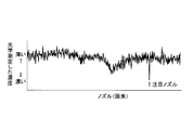
- FIG. 4 is a graph showing the density distribution of each pixel by the ink ejected from each nozzle based on the image signal read by the scanner unit from the print image of the density distribution measurement test pattern printed by the printer unit of FIG. 1 in a single color.
- FIG. 5 is a graph showing an example of a filter waveform applied to the density correction value of the ink discharge amount of each nozzle having the density distribution of FIG.
- FIG. 1 is a block diagram showing a configuration of a control system of a line type ink jet recording apparatus according to an embodiment of the present invention.
- FIG. 2 is an explanatory diagram showing the printer unit shown in FIG. 1 from the side.
- FIG. 6 is an explanatory diagram showing the filter function of each filter shown in FIG.
- FIG. 7 is an explanatory diagram showing the variables of the general formula shown in FIG. 6 and the pixels to be applied for each filter shown in FIG.
- FIG. 8 shows the density distribution of the density correction value of the density correction value in each pixel when each filter shown in FIG. 5 is used according to the distance from the pixel of the nozzle of interest, and the density distribution before density correction in each pixel. It is explanatory drawing typically shown about the range of a part of nozzle.
- FIG. 9 is a graph showing the density distribution of ejected ink that has been subjected to density correction by applying a density correction profile generated from the density profile after the smoothing process.
- FIG. 9 is a graph showing the density distribution of ejected ink that has been subjected to density correction by applying a density correction profile generated from the density profile after the smoothing process.
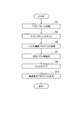
- FIG. 10 is a flowchart showing a procedure when the above-described density correction profile is generated by executing a program stored in the ROM by the CPU of the line type ink jet recording apparatus of FIG.
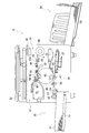
- FIG. 11 is a schematic cross-sectional view showing an internal configuration of a stencil printing apparatus according to another embodiment of the present invention.
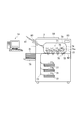
- FIG. 12 is an explanatory diagram showing a schematic configuration of a laser beam printer according to still another embodiment of the present invention.
- FIG. 1 is a block diagram showing a configuration of a control system of a line type ink jet recording apparatus according to an embodiment of the present invention.
- a line-type inkjet recording apparatus (hereinafter abbreviated as “inkjet recording apparatus”) 1 according to the present embodiment includes a scanner unit 101 that reads a document image on a document and outputs an image signal.
- a printer unit 102 that prints (records) a document image on printing paper (one side or both sides) based on an image signal output from the scanner unit 101, a display 103 for various display inputs, and a control unit 10 for overall control. It has.
- the control unit 10 is connected to an external interface unit 15 of a client terminal 14 to be described later via an external interface unit 11.
- the external interface unit 11 and the external interface unit 15 are connected by a wireless or wired communication path SL.
- the control unit 10 receives a print job of the original image from the client terminal 14 via the communication path SL, converts the image data of the original image by the received print job into print gradation data, and based on this, the original document
- the printer unit 102 executes printing of the image on the printing paper.
- a display 103 is connected to the CPU 90 of the control unit 10.
- the display 103 has a touch panel and a plurality of key buttons, and various inputs can be performed by touching the keys displayed on the display 103 on the touch panel or pressing the key buttons. it can.
- the display 103 can also be used as an input operation unit for a user to select and input a mode for converting the image read from the printing paper by the scanner unit 101 into electronic data and a mode such as self-diagnosis using the read image data. it can.
- the control unit 10 of the inkjet recording apparatus 1 that causes the printer unit 102 to perform a printing operation includes a CPU 90.
- the CPU 90 controls the operation of the scanner unit 101 and the printer unit 102 according to the contents input and set from the display 103 based on the program and setting information stored in the ROM 91.
- the control unit 10 is provided with a RAM 92 that functions as a working area of the CPU 90 and a flash memory 93 that is used for storing various firmware and data.
- the client terminal 14 is configured by a PC (personal computer) or the like, and includes a CPU 16 that executes various processes based on a control program stored in the ROM 17, a RAM 18 that functions as a working area of the CPU 16, a keyboard, An input unit 19 composed of a mouse or the like and an output unit 20 composed of a liquid crystal display or the like are provided.
- a PC personal computer
- an external storage device 21 that stores various application programs and data and a disk drive 22 that reads various programs and data from the disk-shaped recording medium 50 are connected to the CPU 16. Yes.
- the CPU 16 When a print command is input from the input unit 19 while the application program is running, the CPU 16 generates a print job by reading out data of a document image to be printed from the external storage device 21 and outputs the print job to the control unit 10. To do.
- the print job can be output to the control unit 10 by the CPU 16 executing the printer driver program stored in the external storage device 21 functioning as a printer driver.
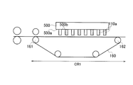
- FIG. 2 is an explanatory diagram showing an image forming path CR1 on which image formation is performed from the side in the printer unit 102 of the inkjet recording apparatus 1 according to the present embodiment, and FIG. 3 is arranged above the image forming path CR1. It is explanatory drawing which shows the head holder 500 of FIG.
- the printer unit 102 of the inkjet recording apparatus 1 includes an image forming path CR1 and a line head 110 that is an image forming unit.
- the image forming path CR1 includes a platen belt 160 that is an endless conveyance belt, a driving roller 161 that is a driving mechanism of the platen belt 160, a driven roller 162, and the like.
- the printing paper is conveyed by the platen belt 160 at a speed determined by the printing conditions.
- a line head 110 is disposed above the platen belt 160 so as to face each other.
- the line head 110 is provided for each color of C (cyan), K (black), M (magenta), and Y (yellow).
- Each color line head 110 is configured by arranging a plurality of head modules 110a in a main scanning direction orthogonal to the sub-scanning direction which is the transport direction (TD) of printing paper.
- Each head module 110a has a nozzle row 110b as schematically shown as one of the K (black) head modules 110a in FIG.
- Each nozzle row 110b is composed of a plurality of nozzles 110c (corresponding to printing elements in the claims) arranged in the main scanning direction.
- Each nozzle 110c ejects ink of each color on the printing paper on the platen belt 160 in units of lines, and forms a plurality of images so as to overlap each other.
- the head module 110a of each color line head 110 is held by a head holder 500 disposed above the platen belt 160 as shown in FIG.
- the head holder 500 is a box having a head holder surface 500a on the bottom surface.
- the head holder surface 500a includes a plurality of mounting openings 500b through which the head module 110a is inserted. Multiple rows are formed in units.
- each mounting opening 500b corresponding to each line head 110 are arranged in a staggered manner, and each mounting opening 500b is formed in the same shape as the horizontal cross section of the head module 110a.
- the head module 110a of each line head 110 is inserted through each mounting opening 500b of the corresponding row, and the nozzle row 110b side protrudes from the head holder surface 500a as shown in FIG.
- the head modules 110a of the line heads 110 of each color held by the head holder 500 are arranged side by side in the main scanning direction, and are arranged by shifting the positions in the sub scanning direction every other line. Has been. As a result, the interval between the nozzles (not shown) at the extreme ends of the two adjacent head modules 110a is made to coincide with the interval between the adjacent nozzles of each head module 110a.
- each head module 110a a plurality of ink chambers (not shown) communicating with the respective nozzles 110c are formed. Ink is supplied to each ink chamber. For example, by changing the volume of each ink chamber using a piezo element, ink in each ink chamber is ejected from each nozzle 110c.
- nozzles 110 c are formed in the head module 110 a of the line head 110 of each color. These nozzles 110c may have variations in ink ejection characteristics even within an allowable range. Variations in the ejection characteristics occur due to, for example, the characteristics of the piezo elements in the ink chamber, manufacturing errors of the nozzle 110c within the tolerance, and the like.
- FIG. 4 is a graph showing the density distribution of each pixel of an image formed on the printing paper with ink ejected by each nozzle 110c of one head module 110a.
- the density distribution shown in the graph of FIG. 4 is obtained from the image signal of the test pattern read by the scanner unit 101 from the print image of the test pattern for density distribution measurement printed in a single color by the printer unit 102 of FIG.
- test pattern for density distribution measurement is an image (test pattern) in which the density gradation value of each pixel corresponding to each nozzle 110c is the same.
- the CPU 90 generates and executes a print job for printing a test pattern for density distribution measurement by using the ink ejected from each nozzle 110c of all the head modules 110a of one line head 110, whereby a print image of the test pattern is generated. Can be obtained.
- each nozzle 110c corresponding to a pixel having the same density gradation value on the printing paper ejects ink, it is printed on the printing paper.
- a density difference occurs between the two pixels.
- a correction profile for each nozzle 110c of all the head modules 110a of one line head 110 can be used.
- the correction profile indicates a correction value (density correction value) of the ink discharge amount of each nozzle 110c corresponding to each pixel so that each pixel has the same density, and is based on the density distribution of FIG. Generated.
- the correction profile can be generated by obtaining a density correction amount that cancels the density difference of each pixel of the density profile.
- the density profile defines the density of each pixel on the print image printed on the printing paper, and is generated from the density of each pixel in the test pattern image signal read by the scanner unit 101 from the test pattern print image. be able to.
- the scanner unit 101 when the printed image of the test pattern is read by the scanner unit 101, the dark colored fibers engraved on the printing paper and the stain on the glass mounting table on which the read original is placed are read together with the test pattern. Thus, noise is superimposed on the image signal.
- a smoothing process such as moving average is performed on the density of each pixel of the density profile acquired from the image signal as a result of reading the test pattern by the scanner unit 101 in order to remove noise components in the image signal.
- the density correction value of the correction profile for the pixel of “target nozzle” is also compressed and becomes a small value, and a density difference remains with the peripheral pixels of the printed image even if the density correction is performed.
- the waveform of the filter used for the smoothing process is changed according to the distance between the pixel whose density is corrected and the pixel of the “target nozzle”.
- FIG. 5 is a graph showing an example of a filter waveform applied to the density correction value of the ink discharge amount of each nozzle 110c having the density distribution of FIG.
- FIG. 5 shows waveforms of five types of filters A to E having different tap numbers and peak values.
- the filters A to E are selectively used according to the distance between the pixel for density correction and the pixel of the “target nozzle”.
- FIG. 6 is an explanatory diagram showing the filter functions of the filters A to E shown in FIG.
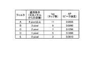
- Each of the filters A to E has different values for the number of taps (tap) and the peak intensity (AP), which are variables of the filter function (Int. (Pixel)) represented by the general formula shown in FIG. Is.
- FIG. 7 is an explanatory diagram showing the variables of the general formula shown in FIG. 6 and the pixels to be applied for each of the filters A to E.
- peak intensity AP 0.0990
- the filter A is applied to a pixel having a distance of 4 pixels or more from the pixel of the “target nozzle”, and the filter B is applied to a pixel having a distance of 3 pixels from the pixel of the “target nozzle”. Similarly, the filters C to E are applied to each pixel whose distance from the pixel of the “target nozzle” is 2 pixels, 1 pixel, and 0 pixel, respectively.
- FIG. 8 shows the distribution of weights in each pixel when the filters A to E are used in accordance with the distance from the pixel of “target nozzle”, together with the density distribution before density correction in each pixel, for some nozzles. It is explanatory drawing shown typically about the range of 110c.
- a filter having a waveform with a smaller number of taps and a higher peak intensity as the pixel is closer to the “target nozzle” pixel, that is, the pixel of the pixel.
- a filter having a strong weight for density is used for the density smoothing process of each pixel in the density profile of FIG.
- the density correction value of the density correction profile thus generated is a value that greatly reduces the density of the density profile in the “target nozzle” pixel that has a large density difference from the surrounding pixels, and in other pixels, This is a value that reduces the density difference from the density.
- FIG. 9 is a graph showing the density distribution of the ejected ink of each nozzle 110c, which is density-corrected by applying a density correction profile generated from the density profile after the smoothing process.
- the broken line in FIG. 9 indicates a case where the density of each pixel in the density profile of FIG. 4 is smoothed by applying the filter A having the smallest peak intensity shown in FIG. Also, the solid line indicates the case where the density of each pixel in the density profile of FIG. 4 is smoothed by applying the filter of FIG.
- the density difference between the pixel of the “target nozzle” and the surrounding pixels is not compressed even by the smoothing process. Therefore, as shown by the solid line in FIG. 9, the density of the ejected ink of the “target nozzle” subjected to density correction by applying the density correction profile generated from the density profile after the smoothing process is smaller than that before density correction.
- the density difference with the pixel is a reduced density.
- the CPU 90 first generates a print job for printing a test pattern for density distribution measurement, and causes the printer unit 102 to print the test pattern on printing paper (step S1).
- a test pattern can be printed by instructing the CPU 90 by an input operation on the display 103.
- the CPU 90 causes the scanner unit 101 to read (scan) the print image of the test pattern from the printing paper on which the test pattern is printed (step S3). Then, the CPU 90 specifies the density of each pixel from the test pattern print image read by the scanner unit 101, and obtains a density profile indicating the distribution of the specified density for each pixel (step S5).
- the CPU 90 extracts, from the acquired density profile, a pixel area of a total of 7 pixels, that is, a pixel of “target nozzle” having a density difference with a peripheral pixel of a certain level or more and three pixels on both sides thereof as a target nozzle area. (Step S7).
- filters B to E other than the filter A of FIG. 5 applied to the density smoothing process of other pixels are applied for the process of smoothing the density of the pixels.
- the CPU 90 applies the filters B to E in FIG. 5 to each pixel in the target nozzle area according to the distance from the pixel of the “target nozzle”, and applies the filter A in FIG. 5 to each other pixel. Then, filtering for smoothing the density of each pixel is performed (step S9). Specifically, the filtering is performed by convolving the functions of the filters A to E applied to each pixel into the density profile.
- the CPU 90 generates a density correction profile in the same procedure as the correction profile based on the density profile after filtering (density profile after the smoothing process), and the density correction profile storage area of the flash memory 93 (in claims) (Corresponding to the profile storage unit) (step S11), the series of processing is terminated.
- step S1 in the flowchart of FIG. 10 is processing corresponding to the test pattern printing step and the test pattern acquisition unit in the claims.
- step S3 and step S5 in FIG. 10 are processing corresponding to the pixel density specifying step and the density profile acquiring step, and the pixel density specifying unit and the density profile acquiring unit in the claims. .
- step S7 in FIG. 10 is processing corresponding to the target pixel extraction step and the target pixel extraction unit in the claims.
- step S9 in FIG. 10 is processing corresponding to the filtering step and the filtering unit in the claims.
- the density gradation value regarding each pixel of the print data generated from the print job by the CPU 90 is Correction is performed by the density correction value of the density correction profile stored in the density correction profile storage area of the flash memory 93. Then, the print job is executed using the print data whose density gradation value is corrected.
- the filters A to E of FIG. 5 having different tap numbers and peak intensities are used depending on the distance from the pixel of the “target nozzle”, and A density smoothing process was performed. Specifically, a pixel having a smaller number of taps and a larger peak intensity is used for a pixel that is closer to the “target nozzle” pixel, and a pixel that is farther from the “nozzle nozzle” pixel has a tap number that is larger.
- the density of each pixel is smoothed using a filter with a waveform having a large peak intensity and a small peak intensity.
- the density unevenness of the print image is appropriately corrected by the density correction value of the density correction profile generated based on the density of the density profile using the filter E of FIG. Can be reduced.
- the filter used for the smoothing process may be different from the filter used for smoothing the “target nozzle” pixel for which smoothing is suppressed.
- the converted density correction value it is possible to smoothly correct the density unevenness of the printed image so that an unnatural density difference does not occur between the target pixel and the peripheral pixels.
- the ink jet recording apparatus 1 of the present embodiment it is possible to generate a density correction profile having appropriate contents.
- the test pattern printing for printing the test pattern for density distribution measurement on the printing paper is performed by the input from the display 103, and the printed image of the printed test pattern is scanned by the scanner unit. 101, the density profile of each pixel is generated from the read image data, a density correction profile is generated based on this, and stored in the density correction profile storage area of the flash memory 93.
- the density profile density is smoothed by the filters A to E according to the distance from the pixel of the “target nozzle”, and the density profile density after the smoothing process is calculated based on the density profile density. A correction value was generated.
- the density correction value of the correction profile is first obtained from the density of the density profile, and the obtained density correction value is smoothed by the filters A to E according to the distance from the pixel of the “target nozzle” to obtain the density correction profile.
- the density correction value may be generated.
- the inkjet recording apparatus 1 that performs printing by the inkjet method has been described as an example.
- the present invention can also be applied to an image forming apparatus other than the inkjet method.
- FIG. 11 is a schematic cross-sectional view showing the internal configuration of a stencil printing apparatus according to another embodiment of the present invention.
- image data of a print job input from an external device or a print job generated by reading an original image by the original reading mechanism 32 (scanner) is controlled by print setting information of the print job. It is processed by the part 38.
- the thermal head 42 (corresponding to the recording head in the claims) of the plate making mechanism 33 is fed from the base paper roll 40 to the platen roller 43 through the guide roller 41, and the stencil base paper 45. Are punched in a pattern according to the document image.
- the stencil sheet 45 made by perforation is cut by a base paper cutter 44 and then wound around a plate cylinder 46 of the printing mechanism 34.
- the ink supplied to the outside of the plate cylinder 46 by the squeegee roll 48 in the plate cylinder 46 facing the press roll 47 is supplied from the back side to the front side through perforation.
- the ink supplied to the surface side of the stencil sheet 45 is fed from the paper feed table 51 of the paper feed mechanism 35 by the scraper 52 and the pickup roll 53 and conveyed to the plate cylinder 46 by the guide roll 54 and the timing roll 55.
- a document image (corresponding to a printing image in claims) is printed on the printing paper 31.
- the thermal head 42 has a large number of heating elements 42a (corresponding to the recording elements in the claims), and each heating element 42a is heated under the control of the control unit 38, so that each of the original images on the stencil sheet 45 is provided. A portion corresponding to each pixel is punched.
- the printing paper 31 after printing is peeled off from the plate cylinder 46 by the paper peeling claw 56 of the paper discharge mechanism 36 and is transported to the stacker unit 58 by the paper transport mechanism 57 to be stacked.
- the stencil sheet 45 after printing is released from the stencil sheet clamp portion 49 of the plate cylinder 46, guided to the plate discharge guide belt 59 of the plate discharge mechanism 37, and peeled off from the plate cylinder 46. 61 is recovered.
- the contamination prevention guide 62 prevents the new stencil sheet 45 wound around the plate cylinder 46 from coming into contact with the plate discharge roller 60.
- each of the thermal heads 42 corresponding to each of the thermal heads 42 that perforate portions corresponding to each pixel of the stencil sheet 45 is provided. It is necessary to correct the amount of heat generated by the heating element 42a according to the density difference between the pixels.
- the density of each pixel of the image formed on the printing paper 31 is specified from the density of each pixel in the read image signal of the test pattern, and a density profile indicating the distribution of the specified density for each pixel is acquired ( Equivalent to step S5 in FIG. 10).
- a pixel area of a total of 7 pixels that is, a pixel of interest having a certain density difference from surrounding pixels and three pixels on both sides thereof is extracted as the pixel of interest area (in step S7 of FIG. 10). Equivalent).
- filters B to E other than the filter A of FIG. 5 applied to the smoothing process of the density of other pixels are applied to the smoothing process of the density of the pixels.
- control unit 38 applies the filters B to E in FIG. 5 to each pixel in the target pixel area according to the distance from the target pixel, and applies the filter A in FIG. 5 to the other pixels. Filtering for smoothing the density of each pixel is performed (corresponding to step S9 in FIG. 10).
- control unit 38 After storing in the memory (corresponding to the profile storage unit in the claims) (corresponding to step S11 in FIG. 10), the series of processing is terminated.
- the correction profile is a correction value for the amount of heat generated by each heating element 42a of the thermal head 42 corresponding to each pixel (heat generation amount correction) so that each pixel of the original image has the same density on the printing paper 31. Value).
- the above-described correction profile can be generated by obtaining a density correction amount that cancels the density difference of each pixel of the density profile.
- the density profile defines the density of each pixel on the print image printed on the printing paper, and is generated from the density of each pixel in the test pattern image signal read by the document reading mechanism 32 from the test pattern print image. can do.
- FIG. 12 is an explanatory diagram showing a schematic configuration of a laser beam printer according to still another embodiment of the present invention.
- the printing unit 71 forms a latent image on the photosensitive drum 72 charged by the charging roller 73 by the drawing light of the writing unit 74.
- the writing unit 74 has a number of LEDs (light emitting diodes) 74a (corresponding to the recording elements in the claims) as a drawing light source. Each LED 74a is turned on under the control of the control unit 83, and the photosensitive drum 72 is turned on. A portion corresponding to each pixel of the original image is exposed.
- LEDs light emitting diodes
- toner is attracted to the latent image by the developing roller 75 to be visualized, and the visualized toner image is fed into the sheet feed tray 77 (first to third sheet feed trays 77a to 77c) or the straight sheet feed stand 78. Then, the toner is transferred by the transfer roller 76 onto the printing paper 31 conveyed to the printing unit 71 by the circulation conveyance path 79. A series of steps from the formation of the latent image to the transfer is performed individually for each color of CKMY.
- the printing paper 31 on which the toner image is transferred and the original image is printed is transported to the paper discharge tray 80 by the circulation transport path 79 and discharged.
- the front and back are reversed by the reverse unit 81 on the back side of the paper discharge tray 80 and conveyed again to the printing unit 71 through the circulation conveyance path 79.
- post-processing binding, sealing, stapling, punching, etc.
- the printed printing paper 31 is transported to the post-processing device (not shown) via a communication transport path 82. Is done.
- An image reading scanner unit 84 (with an automatic document feeder) is provided on the upper part of the image forming apparatus 3.
- the density of each pixel of the image formed on the printing paper 31 is specified from the density of each pixel in the read image signal of the test pattern, and a density profile indicating the distribution of the specified density for each pixel is acquired ( Equivalent to step S5 in FIG. 10).
- a pixel area of a total of 7 pixels that is, a pixel of interest having a certain density difference from surrounding pixels and three pixels on both sides thereof is extracted as the pixel of interest area (in step S7 of FIG. 10). Equivalent).
- filters B to E other than the filter A of FIG. 5 applied to the smoothing process of the density of other pixels are applied to the smoothing process of the density of the pixels.
- control unit 83 applies the filters B to E in FIG. 5 to each pixel in the target pixel area according to the distance from the target pixel, and applies the filter A in FIG. 5 to the other pixels. Filtering for smoothing the density of each pixel is performed (corresponding to step S9 in FIG. 10).
- control unit 83 After storing in the memory (corresponding to the profile storage unit in the claims) (corresponding to step S11 in FIG. 10), the series of processing is terminated.
- the density correction profile is a correction value (light emission intensity correction value) of the light emission intensity of each LED 74a of the writing unit 74 corresponding to each pixel so that each pixel of the original image has the same density on the printing paper 31. ).
- the above-described correction profile can be generated by obtaining a density correction amount that cancels the density difference of each pixel of the density profile.
- the density profile defines the density of each pixel on the print image printed on the printing paper, and is generated from the density of each pixel in the test pattern image signal read by the scanner unit 84 from the test pattern print image. be able to.
- the above-described stencil printing apparatus 2 in FIG. 11 and the electrophotographic image forming apparatus 3 in FIG. 12 can obtain the same effects as those of the inkjet recording apparatus 1 described above.
- a pixel having a certain density difference from surrounding pixels is extracted as a “target nozzle” pixel or a target pixel.
- a pixel whose density difference from surrounding pixels corresponds to a predetermined density difference pattern is designated as a pixel of “target nozzle”.
- the filter waveform applied according to the pixel of the “target nozzle” and the distance from the target pixel is one pattern for each distance.
- a filter to be applied according to the distance from the pixel of interest or pixel of interest for each relevant criterion may be different.
- a filter with a different waveform is used for the density smoothing process depending on which pixel is the “target nozzle” pixel or the target pixel, and the distance from the “target nozzle” pixel or the target pixel. Therefore, smooth smoothing processing can be performed with a filter having a waveform suitable for the density difference pattern between the two pixels.
- the filters A to E having a waveform with a smaller number of taps are used for the smoothing process as the pixel is closer to the “target nozzle” pixel.
- a filter having a waveform in which the range of the target pixel of the filter is determined by an element other than the number of taps is used. Also good.
- the recording existing between the recording elements when the image is recorded on the recording medium by the plurality of recording elements of the recording head. It is possible to generate a density correction profile with appropriate contents for correcting density unevenness of a printed image caused by characteristic variation.
- the recording contents recorded on each pixel of the recording medium by a plurality of recording elements of the recording head include The recording characteristics of the recording element used for pixel recording are reflected.
- the recording content of each pixel of the image recorded by the recording head on the recording medium also varies, and the recording medium is caused by the variation in the recording content.
- Variation in density occurs between the pixels of the printed image obtained from the image.
- the density of each pixel of the print image obtained from the image on the recording medium is corrected by correcting the content recorded on each pixel of the recording medium by each recording element of the recording head according to the density correction content of each pixel of the correction profile. Variation in the density of printed images can be reduced.
- the distance from the target pixel is short.
- a density correction profile is generated in which a function of a filter having a waveform with a narrow range of application target pixels and a high peak intensity is convoluted with the correction profile.
- the generation of the density correction profile may be performed by generating a correction profile from the density profile smoothed by the filter, or may be performed by smoothing the correction profile generated from the density profile by the filter.
- the degree to which the density difference from the surrounding pixels is reflected in the density correction contents of the correction profile gradually and continuously increases.
- the degree to which the smoothing of the density correction content of the profile is smoothly increased.
- the density unevenness of the printed image can be appropriately reduced by the density correction content of the density correction profile generated based on the density correction density or the density correction content of the correction profile in which smoothing is suppressed. .
- the filter used for the smoothing process may be different from the filter used for the smoothing process of the target pixel for which smoothing is suppressed.
- the density unevenness of the printed image can be corrected smoothly so that an unnatural density difference does not occur between the pixels and the peripheral pixels.
- the density correction profile generation method and the image forming apparatus of the image forming apparatus for each density difference pattern (for example, a waveform of a density change between pixels, an acceleration of the density change, etc.) with respect to surrounding pixels.
- the pixel of interest is classified.
- the density correction content defined in the correction profile of the target pixel of each classification and its peripheral pixels, or the waveform corresponding to the classification in the density shown in the density profile of the target pixel of each classification and its peripheral pixels The filter is applied.
- the density correction profile which is the content obtained by convolving the filter function with the correction profile, a waveform corresponding to the density difference pattern between the target pixel and its peripheral pixels whose density difference from the surrounding pixels is equal to or greater than a certain level.
- the print of the density distribution measurement test pattern is read by the scanner and the density of each pixel is specified.
- the density profile indicating the density of each pixel of the image on the recording medium having a causal relationship with the density of the pixel thus obtained can be easily obtained.
- a print image of a test pattern for density distribution measurement is printed and read by a scanner to specify the density of each pixel.
- the effect obtained by the density correction profile generation method of the image forming apparatus according to the first aspect of the present invention can be obtained by a single image forming apparatus.
- the density correction profile is stored in the profile storage unit, and the recording content recorded on each pixel of the recording medium is corrected by the density correction content of the density correction profile.
- the recording characteristic changes a new density correction profile can be generated and the old density correction profile in the profile storage unit can be updated.
- the processing circuit includes a programmed processing device such as a processing device including an electrical circuit.
- Processing devices also include devices such as application specific integrated circuits (ASICs) and conventional circuit components arranged to perform the functions described in the embodiments.
- ASICs application specific integrated circuits
- an appropriate density correction profile for correcting density unevenness of a printed image due to variations in recording characteristics existing between recording elements when an image is recorded on a recording medium by a plurality of recording elements of a recording head is appropriately used. Can be generated with content.
Landscapes
- Engineering & Computer Science (AREA)
- Quality & Reliability (AREA)
- General Engineering & Computer Science (AREA)
- Physics & Mathematics (AREA)
- General Physics & Mathematics (AREA)
- Theoretical Computer Science (AREA)
- Facsimile Image Signal Circuits (AREA)
- Ink Jet (AREA)
- Color, Gradation (AREA)
- Image Processing (AREA)
Abstract
濃度分布測定用のテストパターンから各画素の濃度を特定して、特定した濃度の画素毎の分布を示す濃度プロファイルを取得し、取得した濃度プロファイルから、周辺画素との濃度差が一定以上ある「注目ノズル」とその両側の画素域を注目ノズル域として抽出する。注目ノズル域に属さない画素の濃度の平滑化処理に適用するフィルタAを除くフィルタB~Eを、注目ノズル域の画素の濃度の平滑化処理に適用する。平滑化処理後の濃度プロファイルに基づいて、各画素の濃度差をなくす濃度補正値のプロファイルを生成する。
Description
本発明は、濃度補正プロファイル生成方法及び画像形成装置に関する。
画像形成装置の一つとして、搬送経路上を搬送される記録媒体にインクジェットヘッドの複数のノズルからインクを吐出して画像を形成するインクジェット記録装置がある。インクジェット記録装置では、各ノズル間にインク吐出特性のばらつきがあると、印刷用紙等の記録媒体上に形成されるドットのサイズや位置のずれによって、画像の濃度にムラが生じる。
そこで、ノズル毎のインク吐出特性を測定し、ノズル間のインク吐出特性のばらつきをキャンセルする濃度補正値を算出して、算出した補正値により各ノズルに対応する画素の濃度階調値を補正することが知られている。
濃度補正値は、例えば、各ノズルから吐出させたインク液滴により記録媒体に形成したテストパターン画像をスキャナで読み取り、読み取り結果からノズル間のインク吐出特性のばらつきを数値化することで、算出することができる。
但し、テストパターン画像をスキャナで読み取る際には、例えば、印刷用紙に漉き込まれた濃い色の繊維や読み取り原稿が載置されるガラス製の載置台の汚れがテストパターン画像と共に読み込まれる等して、ノイズが画像信号に重畳されることがある。そこで、スキャナによる読み取り結果の画像信号に対して移動平均等の平滑化処理を施して、画像信号中のノイズ成分を除去することが行われる。
テストパターン画像のスキャナによる読み取り結果の画像信号に対する平滑化処理は、ノズルのインク吐出特性が急峻に変化することで隣接する画素間に生じた濃度の高周波成分のばらつきが、テストパターン画像のスキャナによる読み取り結果の画像信号に含まれている場合にも、同じように施される。濃度の高周波成分のばらつきは、例えば、あるノズルのインク吐出特性が両隣のノズルのインク吐出特性に対して大きく異なる場合に出現する。
濃度の高周波成分のばらつきが、テストパターン画像のスキャナによる読み取り結果の画像信号に含まれていると、平滑化処理後のスキャナによる読み取り結果の画像信号から算出した濃度補正値で各ノズルに対応する画素の濃度階調値を補正しても、高周波成分のインク吐出特性のばらつきによる画像の濃度ムラを十分には解消できない。
そこで、特許文献1によれば、スキャナによる読み取り結果の画像信号に平滑化処理を施す代わりに、スキャナによる読み取り結果の画像信号から高周波帯域を抽出して、抽出した画像信号の高周波帯域からフィルタ等によってノイズ成分を除去することが提案されている。
特許文献1に開示される提案では、ノイズ成分を除去した画像信号の高周波帯域を画像信号の他の周波数帯域と合成した後、合成した画像信号から、各ノズルに対応する画素の濃度階調値の濃度補正値を算出する。
ところが、上述した従来の提案では、スキャナによる読み取り結果の画像信号に平滑化処理を施さないことから、ノイズ成分を除去した画像信号の高周波帯域と、画像信号の他の周波数帯域との接続部分において、画像信号中に現れるノズルのインク吐出特性のばらつきの波形が滑らかに接続されない場合がある。
上述のような場合には、合成した画像信号から算出した濃度補正値により各ノズルに対応する画素の濃度階調値を補正した場合に、スキャナによる読み取り結果の画像信号の高周波帯域と他の周波数帯域との接続部分に対応する画素とその周辺の画素との間に、不自然な濃度差が発生する。接続部分に対応する画素とその周辺の画素との間に発生した濃度差は、記録媒体上に形成される画像の濃度ムラを適切に解消することの妨げとなってしまう。
なお、上述した問題は、例えば、電子写真方式の画像形成装置における描画用光源による感光ドラムへの描画特性のばらつきや、孔版印刷方式の画像形成装置におけるサーマルヘッドによる孔版原紙への穿孔特性のばらつき等が原因で発生することもある。
即ち、上述した問題は、印刷する画像を記録媒体に記録する記録ヘッドの複数の記録素子間に存在する記録特性のばらつきに起因して、各種の記録方式を用いる画像形成装置において共通して発生するものである。
本発明は、以上の点に鑑みてなされたもので、本発明の目的は、記録ヘッドの複数の記録素子により画像を記録媒体に記録する際の記録素子間に存在する記録特性のばらつきに起因する印刷画像の濃度ムラを補正する濃度補正プロファイルを適切な内容で生成することができる濃度補正プロファイルの生成方法と、当該生成方法により生成した濃度補正プロファイルを用いて画像を印刷する際に用いて好適な画像形成装置とを提供することにある。
上述した課題を解決するために、本発明の一態様に係る濃度補正プロファイル生成方法及び画像形成装置は、各記録素子の記録特性に基づいて、記録媒体の画像の各記録素子に対応する各画素の濃度を示す濃度プロファイルを取得し、濃度プロファイルに基づいて、記録媒体の画像中の周辺画素との濃度差が一定以上である注目画素を抽出し、濃度プロファイルに基づいて生成した記録媒体の画像の各画素の濃度補正内容を定義する補正プロファイル、又は、濃度プロファイルに基づいて、注目画素からの距離が近い画素ほど適用対象画素の範囲が狭くピーク強度が大きい波形のフィルタの関数が補正プロファイルに畳み込まれた濃度補正プロファイルを生成する。
また、本発明の一態様に係る濃度補正プロファイル生成方法及び画像形成装置は、注目画素を抽出する際に、注目画素を周辺画素との濃度差パターンに応じて複数に分類し、濃度補正プロファイルを生成する際に、各分類の濃度差パターンに応じた波形のフィルタを各分類の注目画素と周辺画素の濃度又は濃度補正内容にそれぞれ適用する畳み込みを行うものであってもよい。
さらに、本発明の一態様に係る濃度補正プロファイル生成方法及び画像形成装置は、濃度プロファイルを取得する際に、記録ヘッドが記録媒体に記録する濃度分布測定用のテストパターンの画像からテストパターンの印刷画像を得て、テストパターンの印刷画像をスキャナにより読み取ってテストパターンの印刷画像の各画素の濃度を特定し、特定したテストパターンの印刷画像の各画素の濃度から濃度プロファイルを取得するものであってもよい。
以下、本発明の実施形態について、図面を参照して説明する。なお、各図面を通じて同一もしくは同等の部位や構成要素には、同一もしくは同等の符号を付し、その説明を省略もしくは簡略化する。
[ライン型インクジェット記録装置と周辺機器の電気的構成]
図1は本発明の一実施形態に係るライン型インクジェット記録装置の制御系の構成を示すブロック図である。
図1は本発明の一実施形態に係るライン型インクジェット記録装置の制御系の構成を示すブロック図である。
図1に示すように、本実施形態のライン型インクジェット記録装置(以下、「インクジェット記録装置」と略記する。)1は、原稿上の原稿画像を読み取って画像信号を出力するスキャナ部101と、スキャナ部101から出力された画像信号に基づいて印刷用紙(片面又は両面)に原稿画像を印刷(記録)するプリンタ部102と、各種表示入力用のディスプレイ103と、全体制御用の制御ユニット10とを備えている。
制御ユニット10には、外部インタフェース部11を介して、後述するクライアント端末14の外部インタフェース部15が接続されている。外部インタフェース部11と外部インタフェース部15の間は、無線あるいは有線による通信路SLによって接続されている。
制御ユニット10は、通信路SLを介して、原稿画像の印刷ジョブをクライアント端末14から受け取り、受け取った印刷ジョブによる原稿画像の画像データを印刷用階調データに変換し、これに基づいて、原稿画像の印刷用紙に対する印刷をプリンタ部102において実行する。
また、制御ユニット10のCPU90には、ディスプレイ103が接続されている。ディスプレイ103は、タッチパネルと複数のキーボタンとを有しており、ディスプレイ103に表示されたキーにタッチパネル上でタッチしたり、キーボタンを押圧操作したりすることによって、各種の入力を行うことができる。
ディスプレイ103は、スキャナ部101によって印刷用紙から読み取った画像を電子データ化するモードや、読み取った画像のデータを利用する自己診断等のモードを、ユーザが選択入力する入力操作部として利用することもできる。
上述したプリンタ部102に印刷動作を行わせるインクジェット記録装置1の制御ユニット10は、CPU90を備える。CPU90は、ROM91に格納されているプログラム及び設定情報に基づいて、ディスプレイ103から入力設定される内容に応じたスキャナ部101やプリンタ部102の動作を制御する。
なお、制御ユニット10には、CPU90のワーキングエリアとして機能するRAM92と、各種ファームウェアやデータの格納に用いられるフラッシュメモリ93とが設けられている。
クライアント端末14は、PC(パーソナルコンピュータ)等によって構成されるものであり、ROM17に格納された制御プログラムに基づいて各種の処理を実行するCPU16と、CPU16のワーキングエリアとして機能するRAM18と、キーボードやマウス等から構成される入力部19と、液晶ディスプレイ等から構成される出力部20とを備えている。
CPU16には、上述した外部インタフェース部15の他に、各種アプリケーションプログラムやデータ等が格納される外部記憶装置21と、ディスク状記録媒体50から各種プログラムやデータを読み取るディスクドライブ22とが接続されている。
CPU16は、アプリケーションプログラムの起動中に入力部19から印刷指令が入力された場合に、印刷対象の原稿画像のデータを外部記憶装置21から読み出す等して印刷ジョブを生成し、制御ユニット10に出力する。印刷ジョブは、外部記憶装置21に格納されたプリンタドライバプログラムを実行したCPU16がプリンタドライバとして機能することによって、制御ユニット10に出力することができる。
図2は、本実施形態に係るインクジェット記録装置1のプリンタ部102において、画像形成が行われる画像形成経路CR1を側方から示す説明図であり、図3は、画像形成経路CR1の上方に配置される図2のヘッドホルダ500を下方から示す説明図である。
図2に示すように、本実施形態に係るインクジェット記録装置1のプリンタ部102は、画像形成経路CR1と、画像形成部であるラインヘッド110を有している。
画像形成経路CR1は、無端状の搬送ベルトであるプラテンベルト160、プラテンベルト160の駆動機構である駆動ローラ161及び従動ローラ162等から構成される。画像形成経路CR1では、プラテンベルト160によって、印刷条件により定められる速度で印刷用紙が搬送される。プラテンベルト160の上方にはラインヘッド110が対向配置されている。
[ラインヘッドの構成と配置]
ラインヘッド110は、C(シアン)、K(ブラック)、M(マゼンタ)、Y(イエロー)の色別に設けられている。各色のラインヘッド110は、印刷用紙の搬送方向(TD)である副走査方向と直交する主走査方向に、複数のヘッドモジュール110aを並べて構成されている。
ラインヘッド110は、C(シアン)、K(ブラック)、M(マゼンタ)、Y(イエロー)の色別に設けられている。各色のラインヘッド110は、印刷用紙の搬送方向(TD)である副走査方向と直交する主走査方向に、複数のヘッドモジュール110aを並べて構成されている。
各ヘッドモジュール110aは、図3中のK(ブラック)のヘッドモジュール110aの一つに代表して模式的に示すように、ノズル列110bをそれぞれ有している。各ノズル列110bは、主走査方向に並んだ複数のノズル110c(請求項中の記録素子に相当)で構成されている。各ノズル110cは、プラテンベルト160上の印刷用紙に対し、ライン単位で各色のインクを吐出し、複数の画像を互いに重なり合うように形成する。
各色のラインヘッド110のヘッドモジュール110aは、図2に示すように、プラテンベルト160の上方に配置したヘッドホルダ500に保持されている。ヘッドホルダ500は、図3に示すように、ヘッドホルダ面500aを底面に有する函体であり、ヘッドホルダ面500aには、ヘッドモジュール110aを挿通する複数の取付開口部500bが、各ラインヘッド110単位で複数列形成されている。
各ラインヘッド110に対応する複数の取付開口部500bは千鳥状に配列されており、各取付開口部500bは、ヘッドモジュール110aの水平断面と同形状に形成されている。各ラインヘッド110のヘッドモジュール110aは、対応する列の各取付開口部500bにそれぞれ挿通されて、ノズル列110b側を図2に示すようにヘッドホルダ面500aから突出させている。
ヘッドホルダ500に保持された各色のラインヘッド110のヘッドモジュール110aは、図3に示すように、主走査方向に並べて配置されており、かつ、1つおきに副走査方向の位置をずらして配置されている。これにより、隣り合う2つのヘッドモジュール110aの最端部のノズル(図示せず)どうしの間隔が、各ヘッドモジュール110aの隣り合うノズルの間隔と一致するようにしている。
各ヘッドモジュール110aの内部には、各ノズル110cにそれぞれ連通する複数のインク室(図示せず)が形成されている。各インク室にはインクが供給され、例えばピエゾ素子を用いて各インク室の容積を変化させることで、各インク室内のインクが各ノズル110cから吐出される。
[ノズル間のインク吐出特性のばらつきと濃度変化]
ところで、図2を参照して説明したように、各色のラインヘッド110のヘッドモジュール110aには、複数のノズル110cが形成されている。これらのノズル110cには、許容された範囲内であっても、インクの吐出特性にばらつきがある場合がある。吐出特性のばらつきは、例えば、インク室のピエゾ素子の特性や、公差内のノズル110cの製造誤差等によって生じる。
ところで、図2を参照して説明したように、各色のラインヘッド110のヘッドモジュール110aには、複数のノズル110cが形成されている。これらのノズル110cには、許容された範囲内であっても、インクの吐出特性にばらつきがある場合がある。吐出特性のばらつきは、例えば、インク室のピエゾ素子の特性や、公差内のノズル110cの製造誤差等によって生じる。
図4は、1つのヘッドモジュール110aの各ノズル110cによる吐出インクで印刷用紙上に形成される画像の各画素の濃度分布を示すグラフである。図4のグラフに示す濃度分布は、図1のプリンタ部102により単色で印刷した濃度分布測定用のテストパターンの印刷画像からスキャナ部101で読み取ったテストパターンの画像信号から得たものである。
なお、濃度分布測定用のテストパターンは、各ノズル110cに対応する各画素の濃度階調値を同一にした画像(テストパターン)である。1つのラインヘッド110の全てのヘッドモジュール110aの各ノズル110cからの吐出インクにより、濃度分布測定用のテストパターンを印刷する印刷ジョブを、CPU90が生成して実行することで、テストパターンの印刷画像を得ることができる。
各画素の濃度に図4に示す分布のようなばらつきがあると、印刷用紙の同じ濃度階調値の画素に対して対応する各ノズル110cがそれぞれインクを吐出しても、印刷用紙に印刷される画像(印刷画像)上では両画素間に濃度差が生じてしまう。
そのため、図4に示す濃度分布のばらつきをなくすために、各画素に対応する各ノズル110cがそれぞれ吐出するインクの吐出量を、各画素の濃度に応じて補正する必要がある。
[ノズルのインク吐出量補正と補正プロファイル]
濃度分布のばらつきをなくすために行う濃度補正には、1つのラインヘッド110の全てのヘッドモジュール110aの各ノズル110cに関する補正プロファイルを用いることができる。補正プロファイルは、各画素が同じ濃度となるようにするための、各画素に対応する各ノズル110cのインク吐出量の補正値(濃度補正値)を示すもので、図4の濃度分布に基づいて生成される。
濃度分布のばらつきをなくすために行う濃度補正には、1つのラインヘッド110の全てのヘッドモジュール110aの各ノズル110cに関する補正プロファイルを用いることができる。補正プロファイルは、各画素が同じ濃度となるようにするための、各画素に対応する各ノズル110cのインク吐出量の補正値(濃度補正値)を示すもので、図4の濃度分布に基づいて生成される。
補正プロファイルは、濃度プロファイルの各画素の濃度差をキャンセルする濃度の補正量を求めることで生成することができる。濃度プロファイルは、印刷用紙に印刷された印刷画像上での各画素の濃度を定義するもので、テストパターンの印刷画像からスキャナ部101で読み取ったテストパターンの画像信号における各画素の濃度から生成することができる。
補正プロファイルの濃度補正値(請求項中の濃度補正内容に相当)を用いて各ノズル110cによるインクの吐出量を補正することで、各ノズル110cに対応する画素間の濃度のばらつきをキャンセルすることができる。
ところで、各ノズル110cの吐出インクによる各画素間の濃度のばらつきを濃度補正によりキャンセルするために、テストパターンの印刷画像をスキャナ部101により読み取る際には、スキャナ部101から出力されるテストパターンの画像信号にノイズが重畳されることがある。
例えば、テストパターンの印刷画像をスキャナ部101で読み取る際に、印刷用紙に漉き込まれた濃い色の繊維や読み取り原稿が載置されるガラス製の載置台の汚れが、テストパターンと共に読み込まれる等して、ノイズが画像信号に重畳される。
そこで、スキャナ部101によるテストパターンの読み取り結果の画像信号から取得した濃度プロファイルの各画素の濃度に対して、画像信号中のノイズ成分を除去するために、移動平均等の平滑化処理が施される。
[濃度プロファイルの平滑化処理]
ところで、図4の「注目ノズル」の矢印で示す画素のように、周辺の画素の濃度に対して大きい濃度差が存在する場合に、スキャナ部101によるテストパターンの読み取り結果の画像信号から取得した濃度プロファイルの各画素の濃度に平滑化処理を施すと、「注目ノズル」の画素(請求項中の注目画素に相当)と周辺画素との濃度差が平滑化処理によって圧縮される。
ところで、図4の「注目ノズル」の矢印で示す画素のように、周辺の画素の濃度に対して大きい濃度差が存在する場合に、スキャナ部101によるテストパターンの読み取り結果の画像信号から取得した濃度プロファイルの各画素の濃度に平滑化処理を施すと、「注目ノズル」の画素(請求項中の注目画素に相当)と周辺画素との濃度差が平滑化処理によって圧縮される。
すると、「注目ノズル」の画素に対する補正プロファイルの濃度補正値も圧縮されて小さい値となってしまい、濃度補正を行っても印刷画像の周辺画素との間に濃度差が残ってしまう。
そこで、本実施形態のインクジェット記録装置1では、濃度補正を行う画素と「注目ノズル」の画素との距離に応じて、平滑化処理に用いるフィルタの波形を変えるようにしている。
図5は、図4の濃度分布を有する各ノズル110cのインク吐出量の濃度補正値に対して適用するフィルタの波形例を示すグラフである。
図5には、タップ数及びピーク値が互いに異なる5種類のフィルタA~Eの波形が示されている。各フィルタA~Eは、濃度補正を行う画素と「注目ノズル」の画素との距離に応じて使い分けられる。
図6は、図5に示す各フィルタA~Eのフィルタ関数を一般式で示す説明図である。各フィルタA~Eは、図6に示す一般式で表されるフィルタ関数(Int.(pixel))の変数であるタップ数(tap)とピーク強度(AP)の値を、それぞれ異なる値としたものである。
図7は、図6に示す一般式の変数と適用対象の画素とをフィルタA~E毎に示す説明図である。
図7に示すように、フィルタAはタップ数をtap=11、ピーク強度をAP=0.0805とし、フィルタBはタップ数をtap=9、ピーク強度をAP=0.0990とし、フィルタCはタップ数をtap=7、ピーク強度をAP=0.1296とし、フィルタDはタップ数をtap=5、ピーク強度をAP=0.1896とし、フィルタEはタップ数をtap=3、ピーク強度をAP=0.3613としている。
そして、フィルタAは、「注目ノズル」の画素からの距離が4ピクセル(pixel)以上の画素に適用され、フィルタBは、「注目ノズル」の画素からの距離が3ピクセルの画素に適用される。同様に、フィルタC~Eは、「注目ノズル」の画素からの距離がそれぞれ2ピクセル、1ピクセル、0ピクセルである各画素に適用される。
図8は、各フィルタA~Eを「注目ノズル」の画素からの距離に応じて使い分けた場合の各画素における重みの分布を、各画素における濃度補正前の濃度の分布と共に、一部のノズル110cの範囲について模式的に示す説明図である。
図8からも明らかなように、本実施形態のインクジェット記録装置1では、「注目ノズル」の画素からの距離が近い画素ほど、タップ数が少なくピーク強度が大きい波形のフィルタ、つまり、その画素の濃度に対する重みが強いフィルタが、図4の濃度プロファイルにおける各画素の濃度の平滑化処理に用いられる。
[濃度補正プロファイルを用いた濃度補正]
図8の重み分布を有するフィルタで、図4の濃度プロファイルにおける各画素の濃度を平滑化処理すると、平滑化した後の濃度プロファイルから、補正プロファイルと同様の手順で濃度補正プロファイルを生成することができる。
図8の重み分布を有するフィルタで、図4の濃度プロファイルにおける各画素の濃度を平滑化処理すると、平滑化した後の濃度プロファイルから、補正プロファイルと同様の手順で濃度補正プロファイルを生成することができる。
そのようにして生成される濃度補正プロファイルの濃度補正値は、周辺画素との濃度差が大きい「注目ノズル」の画素では、濃度プロファイルの濃度を大きく下げる値となり、他の画素では、周辺画素の濃度との濃度差を小さくする値となる。
図9は、平滑化処理後の濃度プロファイルから生成した濃度補正プロファイルを適用して濃度補正した、各ノズル110cの吐出インクの濃度分布を示すグラフである。
なお、図9中の破線は、図5に示すピーク強度が一番小さいフィルタAを適用して図4の濃度プロファイルにおける各画素の濃度を平滑化処理した場合を示している。また、実線は、図8のフィルタを適用して図4の濃度プロファイルにおける各画素の濃度を平滑化処理した場合をそれぞれ示している。
まず、図5に示すピーク強度が一番小さいフィルタAを適用して図4の濃度プロファイルにおける各画素の濃度を平滑化処理すると、「注目ノズル」の画素と周辺画素との濃度差が平滑化処理によって圧縮される。そのため、平滑化処理後の濃度プロファイルから生成した濃度補正プロファイルを適用して濃度補正した「注目ノズル」の吐出インクの濃度は、図9の破線に示すように、濃度補正前とほとんど変わりのない濃さのままとなる。
一方、図8のフィルタを適用して図4の濃度プロファイルにおける各画素の濃度を平滑化処理すると、「注目ノズル」の画素と周辺画素との濃度差が平滑化処理によっても圧縮されない。そのため、平滑化処理後の濃度プロファイルから生成した濃度補正プロファイルを適用して濃度補正した「注目ノズル」の吐出インクの濃度は、図9の実線に示すように、濃度補正前と比べると、周辺画素との濃度差が縮小する濃度となる。
[インクジェット記録装置による処理例]
次に、本実施形態のインクジェット記録装置1のCPU90がROM91に格納されたプログラムを実行することで上述した濃度補正プロファイルを生成する際の手順について、図10のフローチャートを参照して説明する。
次に、本実施形態のインクジェット記録装置1のCPU90がROM91に格納されたプログラムを実行することで上述した濃度補正プロファイルを生成する際の手順について、図10のフローチャートを参照して説明する。
図10に示すように、CPU90は、まず、濃度分布測定用のテストパターンを印刷させる印刷ジョブを生成し、プリンタ部102においてテストパターンを印刷用紙に印刷させる(ステップS1)。例えば、ディスプレイ103の入力操作によってCPU90に指示し、テストパターンの印刷を実行させることができる。
次に、CPU90は、テストパターンを印刷した印刷用紙からテストパターンの印刷画像をスキャナ部101により読み取り(スキャン)させる(ステップS3)。そして、CPU90は、スキャナ部101に読み取らせたテストパターンの印刷画像から、各画素の濃度を特定して、特定した濃度の画素毎の分布を示す濃度プロファイルを取得する(ステップS5)。
続いて、CPU90は、取得した濃度プロファイルから、周辺画素との濃度差が一定以上ある「注目ノズル」の画素とその両側の3ピクセルずつの、合計7ピクセルの画素域を、注目ノズル域として抽出する(ステップS7)。注目ノズル域では、画素の濃度の平滑化処理のために、他の画素の濃度の平滑化処理に適用する図5のフィルタA以外のフィルタB~Eが適用される。
そこで、CPU90は、注目ノズル域の各画素に、「注目ノズル」の画素からの距離に応じて図5のフィルタB~Eを適用し、他の各画素に、図5のフィルタAを適用して、各画素の濃度を平滑化するフィルタリングを行う(ステップS9)。フィルタリングは、具体的には、濃度プロファイルに各画素に適用するフィルタA~Eの関数を畳み込むことで行われる。
そして、CPU90は、フィルタリング後の濃度プロファイル(平滑化処理後の濃度プロファイル)に基づいて、補正プロファイルと同様の手順で濃度補正プロファイルを生成し、フラッシュメモリ93の濃度補正プロファイル格納領域(請求項中のプロファイル記憶部に相当)に記憶させた後(ステップS11)、一連の処理を終了する。
以上の説明からも明らかなように、本実施形態では、図10のフローチャートにおけるステップS1が、請求項中のテストパターン印刷ステップ及びテストパターン取得部に対応する処理となっている。また、本実施形態では、図10中のステップS3及びステップS5が、請求項中における画素濃度特定ステップ及び濃度プロファイル取得ステップと、画素濃度特定部及び濃度プロファイル取得部に対応する処理となっている。
さらに、本実施形態では、図10中のステップS7が、請求項中の注目画素抽出ステップ及び注目画素抽出部に対応する処理となっている。また、本実施形態では、図10中のステップS9が、請求項中のフィルタリングステップ及びフィルタリング部に対応する処理となっている。
なお、本実施形態のインクジェット記録装置1では、例えばクライアント端末14からの印刷ジョブが外部インタフェース部11に入力されると、CPU90が印刷ジョブから生成した印刷データの各画素に関する濃度階調値が、フラッシュメモリ93の濃度補正プロファイル格納領域に記憶されている濃度補正プロファイルの濃度補正値によって補正される。そして、濃度階調値が補正された印刷データを用いて印刷ジョブが実行される。
以上に説明した本実施形態のインクジェット記録装置1によれば、「注目ノズル」の画素からの距離に応じて、タップ数及びピーク強度が異なる図5のフィルタA~Eを使い分けて、各画素の濃度の平滑化処理を行うようにした。具体的には、「注目ノズル」の画素からの距離が近い画素ほど、タップ数が少なくピーク強度が大きい波形のフィルタを用い、「注目ノズル」の画素からの距離が遠い画素ほど、タップ数が多くピーク強度が小さい波形のフィルタを用いて、各画素の濃度の平滑化処理を行うようにした。
そのため、「注目ノズル」の画素からの距離が近い画素ほど、周辺画素との濃度差が補正プロファイルの濃度補正値に反映される度合いが徐々に連続的に大きくなり、補正プロファイルの濃度補正値の平滑化が抑制される度合いが滑らかに増加する。
よって、「注目ノズル」の画素については平滑化が抑制された図5のフィルタEを用いた濃度プロファイルの濃度に基づいて生成した濃度補正プロファイルの濃度補正値によって、印刷画像の濃度ムラを適切に減らすことができる。
また、「注目ノズル」の画素以外の画素については、平滑化処理に用いるフィルタを、平滑化が抑制される「注目ノズル」の画素の平滑化処理に用いるフィルタと波形が異なるフィルタとしても、平滑化された濃度補正値によって注目画素と周辺画素との間に不自然な濃度差が生じないよう滑らかに印刷画像の濃度ムラを補正できる。
したがって、本実施形態のインクジェット記録装置1によれば、適切な内容の濃度補正プロファイルを生成することができる。
また、本実施形態のインクジェット記録装置1によれば、ディスプレイ103からの入力により濃度分布測定用のテストパターンを印刷用紙に印刷するテストパターン印刷を行い、印刷されたテストパターンの印刷画像をスキャナ部101に読み取らせて、読み取り結果の画像データから各画素の濃度プロファイルを生成し、これを基に濃度補正プロファイルを生成して、フラッシュメモリ93の濃度補正プロファイル格納領域に記憶するようにした。
そのため、例えばヘッドモジュール110aの交換等により各ノズル110cのインク吐出特性に変化が生じた場合に、新しい濃度補正プロファイルを生成してフラッシュメモリ93の濃度補正プロファイル格納領域の古い濃度補正プロファイルを更新することができる。
なお、本実施形態では、濃度プロファイルの濃度を「注目ノズル」の画素からの距離に応じたフィルタA~Eにより平滑化処理し、平滑化処理後の濃度プロファイルの濃度から、濃度補正プロファイルの濃度補正値を生成するものとした。
しかし、濃度プロファイルの濃度から補正プロファイルの濃度補正値を先に求め、求めた濃度補正値を「注目ノズル」の画素からの距離に応じたフィルタA~Eにより平滑化処理して、濃度補正プロファイルの濃度補正値を生成するようにしてもよい。
また、上述した実施形態では、インクジェット方式で印刷を行うインクジェット記録装置1を例に取って説明したが、本発明は、インクジェット方式以外の画像形成装置にも適用可能である。
図11は、本発明の他の実施形態に係る孔版印刷装置の内部構成を示す概略断面図である。
[孔版印刷装置の全体構成]
図11に示す孔版印刷装置2では、外部の機器から入力された印刷ジョブや原稿読取機構32(スキャナ)による原稿画像の読み取りにより発生した印刷ジョブの画像データが、印刷ジョブの印刷設定情報により制御部38で加工される。
図11に示す孔版印刷装置2では、外部の機器から入力された印刷ジョブや原稿読取機構32(スキャナ)による原稿画像の読み取りにより発生した印刷ジョブの画像データが、印刷ジョブの印刷設定情報により制御部38で加工される。
そして、加工された画像データに基づいて、製版機構33のサーマルヘッド42(請求項中の記録ヘッドに相当)が、原紙ロール40からガイドローラ41を介してプラテンローラ43に繰り出された孔版原紙45を、原稿画像に応じたパターンで穿孔する。
穿孔により製版された孔版原紙45は、原紙カッタ44により切断された後に、印刷機構34の版胴46に巻装される。版胴46の孔版原紙45には、プレスロール47に対向する版胴46内のスキージロール48により版胴46の外部に供給されたインクが、穿孔を通じて裏面側から表面側に供給される。
そして、孔版原紙45の表面側に供給されたインクが、給紙機構35の給紙台51からスクレーパ52及びピックアップロール53により繰り出されてガイドロール54及びタイミングロール55により版胴46に搬送された印刷用紙31に転写されることで、印刷用紙31に原稿画像(請求項中の印刷画像に相当)が印刷される。
なお、サーマルヘッド42は多数の発熱体42a(請求項中の記録素子に相当)を有しており、各発熱体42aが制御部38の制御により加熱されて、孔版原紙45における原稿画像の各画素に対応する箇所をそれぞれ穿孔する。
印刷後の印刷用紙31は、排紙機構36の用紙剥取爪56により版胴46から剥ぎ取られて用紙搬送機構57によりスタッカ部58に搬送されて積層される。また、印刷後の孔版原紙45は、版胴46の原紙クランプ部49から解放された後に、排版機構37の排版誘導ベルト59に導かれて版胴46から引き剥がされ、排版ローラ60により排版ボックス61に回収される。
なお、汚染防止ガイド62は、版胴46に巻装される新しい孔版原紙45が排版ローラ60と接触するのを防ぐ。
[サーマルヘッドの穿孔特性のばらつきと濃度変化]
上述のように構成された孔版印刷装置2では、サーマルヘッド42の各発熱体42aによる孔版原紙45の穿孔特性にばらつきがあると、孔版原紙45の同じ濃度階調値の画素に対応する箇所に異なる径の穿孔が形成されてしまい、穿孔後の孔版原紙45を用いて印刷用紙31に原稿画像を印刷すると、印刷用紙31上で原稿画像の両画素間に濃度差が生じてしまう。
上述のように構成された孔版印刷装置2では、サーマルヘッド42の各発熱体42aによる孔版原紙45の穿孔特性にばらつきがあると、孔版原紙45の同じ濃度階調値の画素に対応する箇所に異なる径の穿孔が形成されてしまい、穿孔後の孔版原紙45を用いて印刷用紙31に原稿画像を印刷すると、印刷用紙31上で原稿画像の両画素間に濃度差が生じてしまう。
そのため、孔版印刷装置2においても、印刷用紙31上で印刷画像の画素間に濃度差が生じるのを防ぐために、孔版原紙45の各画素に対応する箇所をそれぞれ穿孔するサーマルヘッド42の対応する各発熱体42aの発熱量を、画素間の濃度差に応じて補正する必要がある。
[濃度補正プロファイルを用いた濃度補正と孔版印刷装置による処理例]
そのためには、先の実施形態と同様に、制御部38の制御の下に、サーマルヘッド42の全ての発熱体42aにより穿孔した孔版原紙45を使って印刷用紙31に印刷したテストパターンの印刷画像を(図10のステップS1に相当)、原稿読取機構32で読み取る(図10のステップS3に相当)。
そのためには、先の実施形態と同様に、制御部38の制御の下に、サーマルヘッド42の全ての発熱体42aにより穿孔した孔版原紙45を使って印刷用紙31に印刷したテストパターンの印刷画像を(図10のステップS1に相当)、原稿読取機構32で読み取る(図10のステップS3に相当)。
そして、読み取ったテストパターンの画像信号における各画素の濃度から、印刷用紙31上に形成される画像の各画素の濃度を特定し、特定した濃度の画素毎の分布を示す濃度プロファイルを取得する(図10のステップS5に相当)。
さらに、取得した濃度プロファイルから、周辺画素との濃度差が一定以上ある注目画素とその両側の3ピクセルずつの、合計7ピクセルの画素域を、注目画素域として抽出する(図10のステップS7に相当)。注目画素域では、画素の濃度の平滑化処理に、他の画素の濃度の平滑化処理に適用する図5のフィルタA以外のフィルタB~Eを適用する。
そこで、制御部38は、注目画素域の各画素に、注目画素からの距離に応じて図5のフィルタB~Eを適用し、他の各画素に、図5のフィルタAを適用して、各画素の濃度を平滑化するフィルタリングを行う(図10のステップS9に相当)。
そして、制御部38は、フィルタリング後の濃度プロファイル(平滑化処理後の濃度プロファイル)に基づいて、補正プロファイルと同様の手順で濃度補正プロファイルを生成し、制御部38に設けた不図示の不揮発性メモリ(請求項中のプロファイル記憶部に相当)に記憶させた後(図10のステップS11に相当)、一連の処理を終了する。
なお、補正プロファイルは、印刷用紙31上で原稿画像の各画素が同じ濃度となるようにするための、各画素に対応するサーマルヘッド42の各発熱体42aの発熱量の補正値(発熱量補正値)を示すものである。
上述の補正プロファイルは、濃度プロファイルの各画素の濃度差をキャンセルする濃度の補正量を求めることで生成することができる。濃度プロファイルは、印刷用紙に印刷された印刷画像上での各画素の濃度を定義するもので、テストパターンの印刷画像から原稿読取機構32で読み取ったテストパターンの画像信号における各画素の濃度から生成することができる。
上述の補正プロファイルの発熱量補正値(請求項中の濃度補正内容に相当)を用いてサーマルヘッド42の各発熱体42aの発熱量を補正することで、各発熱体42aに対応する画素間の濃度のばらつきをキャンセルすることができる。
また、図12は、本発明のさらに他の実施形態に係るレーザビームプリンタの概略構成を示す説明図である。
[電子写真方式の画像形成装置の概略構成]
図12に示す電子写真方式の画像形成装置3では、印刷部71において、帯電ローラ73により帯電させた感光体ドラム72に書き込みユニット74の描画光により潜像を形成する。
図12に示す電子写真方式の画像形成装置3では、印刷部71において、帯電ローラ73により帯電させた感光体ドラム72に書き込みユニット74の描画光により潜像を形成する。
なお、書き込みユニット74は多数のLED(発光ダイオード)74a(請求項中の記録素子に相当)を描画光源として有しており、各LED74aが制御部83の制御により点灯されて、感光体ドラム72における原稿画像の各画素に対応する箇所をそれぞれ露光させる。
そして、現像ローラ75により潜像にトナーを吸着させて顕像化させ、顕像化したトナー像を、給紙トレイ77(第1~第3給紙トレイ77a~77c)やストレート給紙台78から循環搬送路79により印刷部71に搬送した印刷用紙31上に、転写ローラ76によって転写させる。潜像の形成から転写までの一連の工程は、CKMYの各色についてそれぞれ個別に行われる。
トナー像が転写されて原稿画像が印刷された印刷用紙31は、片面印刷の場合、循環搬送路79により排紙トレイ80に搬送されて排紙される。両面印刷の場合は、排紙トレイ80の裏側の反転部81で表裏反転されて、循環搬送路79により再び印刷部71に搬送される。
また、不図示の後処理装置で後処理(製本、封入封緘、ステープル処理、パンチ処理等)を施す場合、印刷後の印刷用紙31は、連絡搬送路82を経て不図示の後処理装置に搬送される。
なお、画像形成装置3の上部には、画像読み取り用のスキャナユニット84(自動原稿送り装置付き)が設けられている。
[書き込みユニットの描画特性のばらつきと濃度変化]
上述のように構成された画像形成装置3では、書き込みユニット74の各LED74aによる感光体ドラム72の描画特性にばらつきがあると、感光体ドラム72の同じ濃度階調値の画素に対応する箇所に異なる径の潜像(ドット)が形成されてしまい、潜像の現像後にトナー像を転写して印刷用紙31に原稿画像を印刷すると、印刷用紙31上で原稿画像の両画素間に濃度差が生じてしまう。
上述のように構成された画像形成装置3では、書き込みユニット74の各LED74aによる感光体ドラム72の描画特性にばらつきがあると、感光体ドラム72の同じ濃度階調値の画素に対応する箇所に異なる径の潜像(ドット)が形成されてしまい、潜像の現像後にトナー像を転写して印刷用紙31に原稿画像を印刷すると、印刷用紙31上で原稿画像の両画素間に濃度差が生じてしまう。
そのため、電子写真方式の画像形成装置3においても、印刷用紙31上で印刷画像の画素間に濃度差が生じるのを防ぐために、感光体ドラム72の各画素に対応する箇所をそれぞれ露光させる書き込みユニット74の対応する各LED74aの発光強度を、画素間の濃度差に応じて補正する必要がある。
[濃度補正プロファイルを用いた濃度補正と画像形成装置による処理例]
そのためには、先の実施形態と同様に、制御部83の制御の下に、書き込みユニット74の全てのLED74aにより潜像(ドット)を形成した感光体ドラム72のトナー像を転写して印刷用紙31に印刷したテストパターンの印刷画像を(図10のステップS1に相当)、スキャナユニット84で読み取る(図10のステップS3に相当)。
そのためには、先の実施形態と同様に、制御部83の制御の下に、書き込みユニット74の全てのLED74aにより潜像(ドット)を形成した感光体ドラム72のトナー像を転写して印刷用紙31に印刷したテストパターンの印刷画像を(図10のステップS1に相当)、スキャナユニット84で読み取る(図10のステップS3に相当)。
そして、読み取ったテストパターンの画像信号における各画素の濃度から、印刷用紙31上に形成される画像の各画素の濃度を特定し、特定した濃度の画素毎の分布を示す濃度プロファイルを取得する(図10のステップS5に相当)。
さらに、取得した濃度プロファイルから、周辺画素との濃度差が一定以上ある注目画素とその両側の3ピクセルずつの、合計7ピクセルの画素域を、注目画素域として抽出する(図10のステップS7に相当)。注目画素域では、画素の濃度の平滑化処理に、他の画素の濃度の平滑化処理に適用する図5のフィルタA以外のフィルタB~Eを適用する。
そこで、制御部83は、注目画素域の各画素に、注目画素からの距離に応じて図5のフィルタB~Eを適用し、他の各画素に、図5のフィルタAを適用して、各画素の濃度を平滑化するフィルタリングを行う(図10のステップS9に相当)。
そして、制御部83は、フィルタリング後の濃度プロファイル(平滑化処理後の濃度プロファイル)に基づいて、補正プロファイルと同様の手順で濃度補正プロファイルを生成し、制御部83に設けた不図示の不揮発性メモリ(請求項中のプロファイル記憶部に相当)に記憶させた後(図10のステップS11に相当)、一連の処理を終了する。
なお、濃度補正プロファイルは、印刷用紙31上で原稿画像の各画素が同じ濃度となるようにするための、各画素に対応する書き込みユニット74の各LED74aの発光強度の補正値(発光強度補正値)を示すものである。
上述の補正プロファイルは、濃度プロファイルの各画素の濃度差をキャンセルする濃度の補正量を求めることで生成することができる。濃度プロファイルは、印刷用紙に印刷された印刷画像上での各画素の濃度を定義するもので、テストパターンの印刷画像からスキャナユニット84で読み取ったテストパターンの画像信号における各画素の濃度から生成することができる。
上述の補正プロファイルの発光強度補正値(請求項中の濃度補正内容に相当)を用いて書き込みユニット74の各LED74aの発光強度を補正することで、各LED74aに対応する画素間の濃度のばらつきをキャンセルすることができる。
以上に説明した図11の孔版印刷装置2や図12の電子写真方式の画像形成装置3でも、先に説明したインクジェット記録装置1と同様の効果を得ることができる。
なお、以上に説明した各実施形態では、周辺画素との濃度差が一定以上ある画素を、「注目ノズル」の画素や注目画素として抽出するものとした。しかし、その代わりに、周辺画素との濃度差が、予め定められた濃度差パターン(例えば、画素間の濃度変化の波形、濃度変化の加速度等)に該当する画素を、「注目ノズル」の画素や注目画素として抽出するようにしてもよい。
また、以上に説明した各実施形態では、「注目ノズル」の画素や注目画素からの距離に応じて適用するフィルタの波形を、各距離についてそれぞれ1パターンとした。しかし、例えば、「注目ノズル」の画素や注目画素であると判定する基準が複数ある場合に、該当した基準毎に、「注目ノズル」の画素や注目画素からの距離に応じて適用するフィルタの波形を異ならせるようにしてもよい。
そのようにすれば、「注目ノズル」の画素や注目画素と判定した際の基準がどれかによって、濃度の平滑化処理に異なる波形のフィルタを、「注目ノズル」の画素や注目画素からの距離に応じて適用して、両画素間の濃度差パターンに適した波形のフィルタで滑らかな平滑化処理が行えるようにすることができる。
さらに、以上に説明した各実施形態では、「注目ノズル」の画素からの距離が近い画素ほどタップ数が小さい波形のフィルタA~Eを平滑化処理に用いるものとした。しかし、「注目ノズル」の画素からの距離が近い画素ほどフィルタを適用する対象画素の範囲が狭いのであれば、タップ数以外の要素によってフィルタの適用対象画素の範囲が定まる波形のフィルタを用いてもよい。
[実施形態の効果]
以上詳細に説明したように、本実施形態に係る濃度補正プロファイル生成方法及び画像形成装置によれば、記録ヘッドの複数の記録素子により画像を記録媒体に記録する際の記録素子間に存在する記録特性のばらつきに起因する印刷画像の濃度ムラを補正する濃度補正プロファイルを適切な内容で生成することができる。
以上詳細に説明したように、本実施形態に係る濃度補正プロファイル生成方法及び画像形成装置によれば、記録ヘッドの複数の記録素子により画像を記録媒体に記録する際の記録素子間に存在する記録特性のばらつきに起因する印刷画像の濃度ムラを補正する濃度補正プロファイルを適切な内容で生成することができる。
即ち、画像形成装置に入力された印刷ジョブにより記録ヘッドが記録媒体に記録する画像から印刷画像を得る場合、記録ヘッドの複数の記録素子が記録媒体の各画素に記録する記録内容には、各画素の記録に使われた記録素子の記録特性が反映される。
そのため、記録ヘッドの各記録素子の記録特性にばらつきがあると、記録ヘッドが記録媒体に記録した画像の各画素の記録内容にもばらつきが生じ、この記録内容のばらつきに起因して、記録媒体の画像から得られる印刷画像の各画素間に濃度のばらつきが生じる。
このように、記録ヘッドの各記録素子の記録特性と、記録ヘッドが記録媒体に記録する画像の各画素の記録内容と、記録媒体の画像から得られる印刷画像の各素子の濃度との間には、相関関係が存在する。
したがって、記録ヘッドの各記録素子の記録特性に基づいて、記録ヘッドが記録媒体に記録する画像の各記録素子に対応する各画素の濃度を示す濃度プロファイルを取得することができる。
そして、取得した濃度プロファイルを用いて、各記録素子の記録特性のばらつきに起因する記録媒体の画像における各画素の濃度のばらつきを補正するための濃度補正内容を定義する補正プロファイルを生成することができる。
即ち、記録ヘッドの各記録素子による記録媒体の各画素への記録内容を、補正プロファイルの各画素の濃度補正内容にしたがって補正することで、記録媒体の画像から得られる印刷画像の各画素の濃度のばらつきを減らし、印刷画像の濃度ムラを補正することができる。
ところで、濃度プロファイル中に周辺画素との濃度差が一定以上となる注目画素が存在する場合、本発明の第1の態様による画像形成装置の濃度補正プロファイル生成方法では、注目画素からの距離が近いほど適用対象画素の範囲が狭くピーク強度が大きい波形のフィルタの関数が補正プロファイルに畳み込まれた濃度補正プロファイルが生成される。
濃度補正プロファイルの生成は、フィルタによって平滑化した濃度プロファイルから補正プロファイルを生成することで行ってもよく、濃度プロファイルから生成した補正プロファイルをフィルタによって平滑化することで行ってもよい。
このようにして生成される濃度補正プロファイルでは、注目画素からの距離が近い画素ほど、周辺画素との濃度差が補正プロファイルの濃度補正内容に反映される度合いが徐々に連続的に大きくなり、補正プロファイルの濃度補正内容の平滑化が抑制される度合いが滑らかに増加する。
よって、注目画素については、平滑化が抑制された濃度プロファイルの濃度又は補正プロファイルの濃度補正内容に基づいて生成した濃度補正プロファイルの濃度補正内容によって、印刷画像の濃度ムラを適切に減らすことができる。
また、注目画素以外の画素については、平滑化処理に用いるフィルタを、平滑化が抑制される注目画素の平滑化処理に用いるフィルタと波形が異なるフィルタとしても、平滑化された濃度補正内容によって注目画素と周辺画素との間に不自然な濃度差が生じないよう滑らかに印刷画像の濃度ムラを補正できる。
したがって、適切な内容の濃度補正プロファイルを生成することができる。
また、本実施形態に係る画像形成装置の濃度補正プロファイル生成方法及び画像形成装置によれば、周辺画素との濃度差パターン(例えば、画素間の濃度変化の波形、濃度変化の加速度等)毎に注目画素が分類される。
そして、各分類の注目画素とその周辺画素の補正プロファイルに定義された濃度補正内容か、あるいは、各分類の注目画素とその周辺画素の濃度プロファイルに示された濃度に、その分類に対応する波形のフィルタが適用される。
そのため、補正プロファイルにフィルタの関数を畳み込んだ内容となる濃度補正プロファイルにおいて、周辺画素との濃度差が一定以上である注目画素とその周辺画素に、両画素間の濃度差パターンに応じた波形のフィルタを用いて、注目画素と周辺画素との濃度差が濃度補正プロファイルの濃度補正内容に反映される度合いを、両画素間の濃度差パターン毎に個別に設定することができる。
さらに、本実施形態に係る画像形成装置の濃度補正プロファイル生成方法及び画像形成装置によれば、濃度分布測定用のテストパターンの印刷画像をスキャナにより読み取って各画素の濃度を特定することで、特定した画素の濃度と因果関係を有する記録媒体の画像の各画素の濃度を示す濃度プロファイルを、容易に取得することができる。
また、本実施形態に係る画像形成装置の濃度補正プロファイル生成方法及び画像形成装置によれば、濃度分布測定用のテストパターンの印刷画像を印刷してスキャナにより読み取り各画素の濃度を特定することで、本発明の第1の態様による画像形成装置の濃度補正プロファイル生成方法によって得られる効果を、単体の画像形成装置によって得ることができる。
しかも、濃度補正プロファイルをプロファイル記憶部に記憶し、その濃度補正プロファイルの濃度補正内容によって、記録媒体の各画素に記録する記録内容を補正することから、例えば記録ヘッドの交換等により各記録素子の記録特性に変化が生じた場合に、新しい濃度補正プロファイルを生成してプロファイル記憶部の古い濃度補正プロファイルを更新することができる。
以上、実施形態に沿って本発明の内容を説明したが、本発明はこれらの記載に限定されるものではなく、種々の変形及び改良が可能であることは、当業者には自明である。この開示の一部をなす論述及び図面は本発明を限定するものであると理解すべきではない。この開示から当業者には様々な代替実施形態、実施例及び運用技術が明らかとなろう。
本発明はここでは記載していない様々な実施形態等を含むことは勿論である。したがって、本発明の技術的範囲は上記の説明から妥当な請求の範囲に係る発明特定事項によってのみ定められるものである。
上述の各実施形態で示した各機能は、1又は複数の処理回路により実装され得る。処理回路は、電気回路を含む処理装置等のプログラムされた処理装置を含む。処理装置は、また、実施形態に記載された機能を実行するようにアレンジされた特定用途向け集積回路(ASIC)や従来型の回路部品のような装置を含む。
本出願は、2017年3月23日に出願された日本国特許願第2017-057432に基づく優先権を主張しており、この出願の全内容が参照により本明細書に組み込まれる。
本発明によれば、記録ヘッドの複数の記録素子により画像を記録媒体に記録する際の記録素子間に存在する記録特性のばらつきに起因する印刷画像の濃度ムラを補正する濃度補正プロファイルを適切な内容で生成することができる。
1 ライン型インクジェット記録装置(画像形成装置)
2 孔版印刷装置(画像形成装置)
3 画像形成装置
10 制御ユニット
11 外部インタフェース部
14 クライアント端末
15 外部インタフェース部
16,90 CPU
17,91 ROM
18,92 RAM
19 入力部
20 出力部
21 外部記憶装置
22 ディスクドライブ
31 印刷用紙
32 原稿読取機構
33 製版機構
34 印刷機構
35 給紙機構
36 排紙機構
37 排版機構
38 制御部
40 原紙ロール
41 ガイドローラ
42 サーマルヘッド
42a 発熱体(記録素子)
43 プラテンローラ
44 原紙カッタ
45 孔版原紙
46 版胴
47 プレスロール
48 スキージロール
49 原紙クランプ部
50 ディスク状記録媒体
51 給紙台
52 スクレーパ
53 ピックアップロール
54 ガイドロール
55 タイミングロール
56 用紙剥取爪
57 用紙搬送機構
58 スタッカ部
59 排版誘導ベルト
60 排版ローラ
61 排版ボックス
62 汚染防止ガイド
71 印刷部
72 感光体ドラム
73 帯電ローラ
74 書き込みユニット
74a LED(発光ダイオード、記録素子)
75 現像ローラ
76 転写ローラ
77 給紙トレイ
77a 第1給紙トレイ
77b 第2給紙トレイ
77c 第3給紙トレイ
78 ストレート給紙台
79 循環搬送路
80 排紙トレイ
81 反転部
82 連絡搬送路
83 制御部
84 スキャナユニット
93 フラッシュメモリ(プロファイル記憶部)
101 スキャナ部
102 プリンタ部
103 ディスプレイ
110 ラインヘッド
110a ヘッドモジュール
110b ノズル列
110c ノズル(記録素子)
160 プラテンベルト
161 駆動ローラ
162 従動ローラ
500 ヘッドホルダ
500a ヘッドホルダ面
500b 取付開口部
CR1 画像形成経路
2 孔版印刷装置(画像形成装置)
3 画像形成装置
10 制御ユニット
11 外部インタフェース部
14 クライアント端末
15 外部インタフェース部
16,90 CPU
17,91 ROM
18,92 RAM
19 入力部
20 出力部
21 外部記憶装置
22 ディスクドライブ
31 印刷用紙
32 原稿読取機構
33 製版機構
34 印刷機構
35 給紙機構
36 排紙機構
37 排版機構
38 制御部
40 原紙ロール
41 ガイドローラ
42 サーマルヘッド
42a 発熱体(記録素子)
43 プラテンローラ
44 原紙カッタ
45 孔版原紙
46 版胴
47 プレスロール
48 スキージロール
49 原紙クランプ部
50 ディスク状記録媒体
51 給紙台
52 スクレーパ
53 ピックアップロール
54 ガイドロール
55 タイミングロール
56 用紙剥取爪
57 用紙搬送機構
58 スタッカ部
59 排版誘導ベルト
60 排版ローラ
61 排版ボックス
62 汚染防止ガイド
71 印刷部
72 感光体ドラム
73 帯電ローラ
74 書き込みユニット
74a LED(発光ダイオード、記録素子)
75 現像ローラ
76 転写ローラ
77 給紙トレイ
77a 第1給紙トレイ
77b 第2給紙トレイ
77c 第3給紙トレイ
78 ストレート給紙台
79 循環搬送路
80 排紙トレイ
81 反転部
82 連絡搬送路
83 制御部
84 スキャナユニット
93 フラッシュメモリ(プロファイル記憶部)
101 スキャナ部
102 プリンタ部
103 ディスプレイ
110 ラインヘッド
110a ヘッドモジュール
110b ノズル列
110c ノズル(記録素子)
160 プラテンベルト
161 駆動ローラ
162 従動ローラ
500 ヘッドホルダ
500a ヘッドホルダ面
500b 取付開口部
CR1 画像形成経路
Claims (4)
- 画像形成装置に入力された印刷ジョブにより複数の記録素子を有する記録ヘッドが記録媒体に記録する画像から得られる印刷画像の、前記各記録媒体の記録特性に起因する濃度ムラを補正する濃度補正プロファイルを生成する方法であって、
前記各記録素子の記録特性に基づいて、前記記録媒体の画像の前記各記録素子に対応する各画素の濃度を示す濃度プロファイルを取得する濃度プロファイル取得ステップと、
前記濃度プロファイルに基づいて、前記記録媒体の画像中の周辺画素との濃度差が一定以上である注目画素を抽出する注目画素抽出ステップと、
前記濃度プロファイルに基づいて生成した前記記録媒体の画像の各画素の濃度補正内容を定義する補正プロファイル、又は、前記濃度プロファイルに基づいて、
前記注目画素からの距離が近い画素ほど適用対象画素の範囲が狭くピーク強度が大きい波形のフィルタの関数が前記補正プロファイルに畳み込まれた前記濃度補正プロファイルを生成するフィルタリングステップと、
を含む濃度補正プロファイル生成方法。 - 請求項1に記載の濃度補正プロファイル生成方法であって、
前記注目画素抽出ステップにおいて、前記注目画素を周辺画素との濃度差パターンに応じて複数に分類し、
前記フィルタリングステップにおいて、各分類の濃度差パターンに応じた波形の前記フィルタを各分類の前記注目画素と周辺画素の濃度又は濃度補正内容にそれぞれ適用する畳み込みを行うこと
を特徴とする濃度補正プロファイル生成方法。 - 請求項1又は2に記載の濃度補正プロファイル生成方法であって、
前記濃度プロファイル取得ステップは、
前記記録ヘッドが前記記録媒体に記録する濃度分布測定用のテストパターンの画像から前記テストパターンの印刷画像を得るテストパターン印刷ステップと、
前記テストパターンの印刷画像をスキャナにより読み取って前記テストパターンの印刷画像の各画素の濃度を特定する画素濃度特定ステップと
を含んでおり、
前記濃度プロファイル取得ステップは、前記画素濃度特定ステップで特定した前記テストパターンの印刷画像の各画素の濃度から前記濃度プロファイルを取得すること
を特徴とする濃度補正プロファイル生成方法。 - 入力された印刷ジョブにより記録ヘッドの複数の記録素子が記録媒体に記録する画像から印刷画像を得る画像形成装置であって、
前記記録ヘッドが前記記録媒体に記録する濃度分布測定用のテストパターンの画像から前記テストパターンの印刷画像を得るテストパターン取得部と、
前記記録媒体の画像の前記各記録素子に対応する各画素の濃度を示す濃度プロファイルを取得する指令をトリガとしてスキャナにより読み取った、前記テストパターンの印刷画像の画像信号から、前記テストパターンの印刷画像の各画素の濃度を特定する画素濃度特定部と、
前記テストパターンの印刷画像の濃度分布に基づいて、前記記録媒体の画像の各画素の濃度を示す濃度プロファイルを取得する濃度プロファイル取得部と、
前記濃度プロファイルに基づいて、前記印刷画像における周辺画素との濃度差が一定以上となる注目画素を抽出する注目画素抽出部と、
前記濃度プロファイルに基づいて生成した前記記録媒体の画像の各画素の濃度補正内容を定義する補正プロファイル又は、前記濃度プロファイルに基づいて、前記注目画素からの距離が近い画素ほど適用対象画素の範囲が狭くピーク強度が大きい波形のフィルタの関数が前記補正プロファイルに畳み込まれた濃度補正プロファイルを生成するフィルタリング部と、
前記濃度補正プロファイルを記憶するプロファイル記憶部と
を備え、
前記記録ヘッドの各記録素子は、前記記録媒体の各画素に記録する記録内容を前記プロファイル記憶部の前記濃度補正プロファイルの濃度補正内容により補正すること
を特徴とする画像形成装置。
Priority Applications (2)
| Application Number | Priority Date | Filing Date | Title |
|---|---|---|---|
| US16/481,653 US10759184B2 (en) | 2017-03-23 | 2018-03-14 | Density correction profile generation method and image forming device |
| JP2019507596A JP6735412B2 (ja) | 2017-03-23 | 2018-03-14 | 濃度補正プロファイル生成方法及び画像形成装置 |
Applications Claiming Priority (2)
| Application Number | Priority Date | Filing Date | Title |
|---|---|---|---|
| JP2017057432 | 2017-03-23 | ||
| JP2017-057432 | 2017-03-23 |
Publications (1)
| Publication Number | Publication Date |
|---|---|
| WO2018173886A1 true WO2018173886A1 (ja) | 2018-09-27 |
Family
ID=63584570
Family Applications (1)
| Application Number | Title | Priority Date | Filing Date |
|---|---|---|---|
| PCT/JP2018/009987 Ceased WO2018173886A1 (ja) | 2017-03-23 | 2018-03-14 | 濃度補正プロファイル生成方法及び画像形成装置 |
Country Status (3)
| Country | Link |
|---|---|
| US (1) | US10759184B2 (ja) |
| JP (1) | JP6735412B2 (ja) |
| WO (1) | WO2018173886A1 (ja) |
Families Citing this family (2)
| Publication number | Priority date | Publication date | Assignee | Title |
|---|---|---|---|---|
| JP2021053995A (ja) | 2019-09-30 | 2021-04-08 | キヤノン株式会社 | 画像処理装置、画像処理方法及びプログラム |
| JP7471791B2 (ja) * | 2019-09-30 | 2024-04-22 | キヤノン株式会社 | 画像処理装置、画像処理方法及びプログラム |
Citations (3)
| Publication number | Priority date | Publication date | Assignee | Title |
|---|---|---|---|---|
| JP2009234018A (ja) * | 2008-03-27 | 2009-10-15 | Seiko Epson Corp | 補正値算出方法及び印刷方法 |
| JP2009302608A (ja) * | 2008-06-10 | 2009-12-24 | Seiko Epson Corp | 補正値算出方法及び印刷方法 |
| JP2012147126A (ja) * | 2011-01-07 | 2012-08-02 | Fujifilm Corp | 濃度むら補正値算出方法及び画像処理方法並びに画像処理装置 |
Family Cites Families (3)
| Publication number | Priority date | Publication date | Assignee | Title |
|---|---|---|---|---|
| JP2009234115A (ja) * | 2008-03-27 | 2009-10-15 | Seiko Epson Corp | 補正値算出方法、及び、液体吐出方法 |
| JP5776250B2 (ja) * | 2011-03-24 | 2015-09-09 | セイコーエプソン株式会社 | 液体吐出装置 |
| JP2014072851A (ja) | 2012-10-01 | 2014-04-21 | Fujifilm Corp | 画像記録装置、画像処理方法及び画像処理プログラム |
-
2018
- 2018-03-14 WO PCT/JP2018/009987 patent/WO2018173886A1/ja not_active Ceased
- 2018-03-14 JP JP2019507596A patent/JP6735412B2/ja active Active
- 2018-03-14 US US16/481,653 patent/US10759184B2/en active Active
Patent Citations (3)
| Publication number | Priority date | Publication date | Assignee | Title |
|---|---|---|---|---|
| JP2009234018A (ja) * | 2008-03-27 | 2009-10-15 | Seiko Epson Corp | 補正値算出方法及び印刷方法 |
| JP2009302608A (ja) * | 2008-06-10 | 2009-12-24 | Seiko Epson Corp | 補正値算出方法及び印刷方法 |
| JP2012147126A (ja) * | 2011-01-07 | 2012-08-02 | Fujifilm Corp | 濃度むら補正値算出方法及び画像処理方法並びに画像処理装置 |
Also Published As
| Publication number | Publication date |
|---|---|
| JPWO2018173886A1 (ja) | 2019-11-21 |
| US20200001618A1 (en) | 2020-01-02 |
| JP6735412B2 (ja) | 2020-08-05 |
| US10759184B2 (en) | 2020-09-01 |
Similar Documents
| Publication | Publication Date | Title |
|---|---|---|
| JP5283685B2 (ja) | 不良記録素子の検出装置及び方法、並びに画像形成装置及び方法 | |
| JP5619041B2 (ja) | 吐出不良検出方法及び装置、画像処理装置、プログラム、並びに印刷システム | |
| EP1221371B1 (en) | Determination of value of adjustment for recording position variation in printing using two types of inspection pattern | |
| US8888217B2 (en) | Inkjet recording apparatus and method, and abnormal nozzle determination method | |
| EP1798037B1 (en) | Image recording apparatus and image recording method | |
| JP5681476B2 (ja) | 不良記録素子の検出装置及び方法、並びに画像形成装置及び方法 | |
| US9152890B2 (en) | Image recording method and apparatus, and recording medium | |
| JP6344862B2 (ja) | 検査装置、検査方法及びプログラム、画像記録装置 | |
| JP6945060B2 (ja) | 画像形成装置及び方法、異常ノズル検出方法並びに印刷物の製造方法 | |
| JP4823599B2 (ja) | 打滴位置誤差の調整方法、打滴制御方法、並びに画像形成装置 | |
| JP2007296754A (ja) | インクジェット記録方法およびミスト低減条件設定装置 | |
| JP6814883B2 (ja) | 画像形成装置及び画像形成方法 | |
| JP6735412B2 (ja) | 濃度補正プロファイル生成方法及び画像形成装置 | |
| US8164791B2 (en) | Image recording apparatus and method | |
| JP2748321B2 (ja) | 画像形成装置 | |
| US8057007B2 (en) | Image recording apparatus and method, and method of determining density correction coefficients | |
| JP6558116B2 (ja) | インクジェット記録装置、インク吐出異常検出方法及び初期ずれ検出方法 | |
| US8047627B2 (en) | Inkjet printing correction method and inkjet printing apparatus | |
| US8837002B2 (en) | Image forming apparatus performing image forming by superimposing images of at least two colors, image forming system, and color shift correction method | |
| US11034169B2 (en) | Image forming apparatus capable of minimizing size of blank area, image forming method | |
| US20230101942A1 (en) | Recording apparatus, recording/reading system and recording method | |
| JP2026002409A (ja) | 画像形成装置、調整方法 | |
| JP2018086838A (ja) | 撮像装置、画像形成装置、実距離算出方法、およびプログラム | |
| JP2025182965A (ja) | 画像形成装置、姿勢調整方法、画像形成方法 | |
| JP2025007941A (ja) | インクジェット記録装置、及び異常ノズル判定方法 |
Legal Events
| Date | Code | Title | Description |
|---|---|---|---|
| 121 | Ep: the epo has been informed by wipo that ep was designated in this application |
Ref document number: 18771127 Country of ref document: EP Kind code of ref document: A1 |
|
| ENP | Entry into the national phase |
Ref document number: 2019507596 Country of ref document: JP Kind code of ref document: A |
|
| NENP | Non-entry into the national phase |
Ref country code: DE |
|
| 122 | Ep: pct application non-entry in european phase |
Ref document number: 18771127 Country of ref document: EP Kind code of ref document: A1 |