WO2018173633A1 - トルクリミッタ - Google Patents
トルクリミッタ Download PDFInfo
- Publication number
- WO2018173633A1 WO2018173633A1 PCT/JP2018/006833 JP2018006833W WO2018173633A1 WO 2018173633 A1 WO2018173633 A1 WO 2018173633A1 JP 2018006833 W JP2018006833 W JP 2018006833W WO 2018173633 A1 WO2018173633 A1 WO 2018173633A1
- Authority
- WO
- WIPO (PCT)
- Prior art keywords
- input
- output
- plate
- applied voltage
- torque
- Prior art date
- Legal status (The legal status is an assumption and is not a legal conclusion. Google has not performed a legal analysis and makes no representation as to the accuracy of the status listed.)
- Ceased
Links
Images
Classifications
-
- F—MECHANICAL ENGINEERING; LIGHTING; HEATING; WEAPONS; BLASTING
- F16—ENGINEERING ELEMENTS AND UNITS; GENERAL MEASURES FOR PRODUCING AND MAINTAINING EFFECTIVE FUNCTIONING OF MACHINES OR INSTALLATIONS; THERMAL INSULATION IN GENERAL
- F16D—COUPLINGS FOR TRANSMITTING ROTATION; CLUTCHES; BRAKES
- F16D7/00—Slip couplings, e.g. slipping on overload, for absorbing shock
- F16D7/02—Slip couplings, e.g. slipping on overload, for absorbing shock of the friction type
-
- B—PERFORMING OPERATIONS; TRANSPORTING
- B25—HAND TOOLS; PORTABLE POWER-DRIVEN TOOLS; MANIPULATORS
- B25J—MANIPULATORS; CHAMBERS PROVIDED WITH MANIPULATION DEVICES
- B25J19/00—Accessories fitted to manipulators, e.g. for monitoring, for viewing; Safety devices combined with or specially adapted for use in connection with manipulators
-
- F—MECHANICAL ENGINEERING; LIGHTING; HEATING; WEAPONS; BLASTING
- F16—ENGINEERING ELEMENTS AND UNITS; GENERAL MEASURES FOR PRODUCING AND MAINTAINING EFFECTIVE FUNCTIONING OF MACHINES OR INSTALLATIONS; THERMAL INSULATION IN GENERAL
- F16D—COUPLINGS FOR TRANSMITTING ROTATION; CLUTCHES; BRAKES
- F16D27/00—Magnetically- or electrically- actuated clutches; Control or electric circuits therefor
- F16D27/02—Magnetically- or electrically- actuated clutches; Control or electric circuits therefor with electromagnets incorporated in the clutch, i.e. with collecting rings
- F16D27/04—Magnetically- or electrically- actuated clutches; Control or electric circuits therefor with electromagnets incorporated in the clutch, i.e. with collecting rings with axially-movable friction surfaces
- F16D27/06—Magnetically- or electrically- actuated clutches; Control or electric circuits therefor with electromagnets incorporated in the clutch, i.e. with collecting rings with axially-movable friction surfaces with friction surfaces arranged within the flux
-
- F—MECHANICAL ENGINEERING; LIGHTING; HEATING; WEAPONS; BLASTING
- F16—ENGINEERING ELEMENTS AND UNITS; GENERAL MEASURES FOR PRODUCING AND MAINTAINING EFFECTIVE FUNCTIONING OF MACHINES OR INSTALLATIONS; THERMAL INSULATION IN GENERAL
- F16D—COUPLINGS FOR TRANSMITTING ROTATION; CLUTCHES; BRAKES
- F16D27/00—Magnetically- or electrically- actuated clutches; Control or electric circuits therefor
- F16D27/12—Clutch systems with a plurality of electro-magnetically-actuated clutches
-
- F—MECHANICAL ENGINEERING; LIGHTING; HEATING; WEAPONS; BLASTING
- F16—ENGINEERING ELEMENTS AND UNITS; GENERAL MEASURES FOR PRODUCING AND MAINTAINING EFFECTIVE FUNCTIONING OF MACHINES OR INSTALLATIONS; THERMAL INSULATION IN GENERAL
- F16D—COUPLINGS FOR TRANSMITTING ROTATION; CLUTCHES; BRAKES
- F16D27/00—Magnetically- or electrically- actuated clutches; Control or electric circuits therefor
- F16D27/14—Details
-
- F—MECHANICAL ENGINEERING; LIGHTING; HEATING; WEAPONS; BLASTING
- F16—ENGINEERING ELEMENTS AND UNITS; GENERAL MEASURES FOR PRODUCING AND MAINTAINING EFFECTIVE FUNCTIONING OF MACHINES OR INSTALLATIONS; THERMAL INSULATION IN GENERAL
- F16D—COUPLINGS FOR TRANSMITTING ROTATION; CLUTCHES; BRAKES
- F16D7/00—Slip couplings, e.g. slipping on overload, for absorbing shock
- F16D7/02—Slip couplings, e.g. slipping on overload, for absorbing shock of the friction type
- F16D7/024—Slip couplings, e.g. slipping on overload, for absorbing shock of the friction type with axially applied torque limiting friction surfaces
- F16D7/025—Slip couplings, e.g. slipping on overload, for absorbing shock of the friction type with axially applied torque limiting friction surfaces with flat clutching surfaces, e.g. discs
-
- B—PERFORMING OPERATIONS; TRANSPORTING
- B60—VEHICLES IN GENERAL
- B60W—CONJOINT CONTROL OF VEHICLE SUB-UNITS OF DIFFERENT TYPE OR DIFFERENT FUNCTION; CONTROL SYSTEMS SPECIALLY ADAPTED FOR HYBRID VEHICLES; ROAD VEHICLE DRIVE CONTROL SYSTEMS FOR PURPOSES NOT RELATED TO THE CONTROL OF A PARTICULAR SUB-UNIT
- B60W2710/00—Output or target parameters relating to a particular sub-units
- B60W2710/06—Combustion engines, Gas turbines
- B60W2710/0666—Engine torque
-
- B—PERFORMING OPERATIONS; TRANSPORTING
- B60—VEHICLES IN GENERAL
- B60W—CONJOINT CONTROL OF VEHICLE SUB-UNITS OF DIFFERENT TYPE OR DIFFERENT FUNCTION; CONTROL SYSTEMS SPECIALLY ADAPTED FOR HYBRID VEHICLES; ROAD VEHICLE DRIVE CONTROL SYSTEMS FOR PURPOSES NOT RELATED TO THE CONTROL OF A PARTICULAR SUB-UNIT
- B60W30/00—Purposes of road vehicle drive control systems not related to the control of a particular sub-unit, e.g. of systems using conjoint control of vehicle sub-units
- B60W30/18—Propelling the vehicle
- B60W30/188—Controlling power parameters of the driveline, e.g. determining the required power
-
- F—MECHANICAL ENGINEERING; LIGHTING; HEATING; WEAPONS; BLASTING
- F16—ENGINEERING ELEMENTS AND UNITS; GENERAL MEASURES FOR PRODUCING AND MAINTAINING EFFECTIVE FUNCTIONING OF MACHINES OR INSTALLATIONS; THERMAL INSULATION IN GENERAL
- F16D—COUPLINGS FOR TRANSMITTING ROTATION; CLUTCHES; BRAKES
- F16D27/00—Magnetically- or electrically- actuated clutches; Control or electric circuits therefor
- F16D27/10—Magnetically- or electrically- actuated clutches; Control or electric circuits therefor with an electromagnet not rotating with a clutching member, i.e. without collecting rings
- F16D27/108—Magnetically- or electrically- actuated clutches; Control or electric circuits therefor with an electromagnet not rotating with a clutching member, i.e. without collecting rings with axially movable clutching members
- F16D27/112—Magnetically- or electrically- actuated clutches; Control or electric circuits therefor with an electromagnet not rotating with a clutching member, i.e. without collecting rings with axially movable clutching members with flat friction surfaces, e.g. discs
-
- F—MECHANICAL ENGINEERING; LIGHTING; HEATING; WEAPONS; BLASTING
- F16—ENGINEERING ELEMENTS AND UNITS; GENERAL MEASURES FOR PRODUCING AND MAINTAINING EFFECTIVE FUNCTIONING OF MACHINES OR INSTALLATIONS; THERMAL INSULATION IN GENERAL
- F16D—COUPLINGS FOR TRANSMITTING ROTATION; CLUTCHES; BRAKES
- F16D67/00—Combinations of couplings and brakes; Combinations of clutches and brakes
- F16D67/02—Clutch-brake combinations
- F16D67/06—Clutch-brake combinations electromagnetically actuated
Definitions
- the present invention relates to a torque limiter. More specifically, the present invention relates to a torque limit value, which is an upper limit value of torque transmitted from the input side to the output side. The present invention relates to a torque limiter that takes safety into account.
- a torque limiter that cuts off the transmission of torque when the torque transmitted from the input side to the output side is in an overload state exceeding a predetermined value.
- this torque limiter for example, as disclosed in Patent Document 1, there is one using an electromagnetic clutch that transmits torque from the input side to the output side using a magnetic force generated by energization.
- a torque limiter is disposed between the robot arm and the motor that operates the robot arm, and when an overload occurs between them, the transmission of torque between the motor and the robot arm is cut off. It is conceivable to provide it.
- the present invention has been devised by paying attention to such a problem.
- the purpose of the present invention is to make the torque limit value variable at the time of torque transmission from the input side to the output side. It is intended to provide a torque limiter that takes into account safety in case of power loss or emergency stop.
- the present invention is mainly configured so that the magnitude of the torque limit value that is the upper limit value of the torque transmitted from the input side member to the output side member can be electromagnetically adjusted.
- a torque limiter disposed between the input side member and the output side member, the input unit and the output unit by adjusting the magnetic force between them.
- the connecting structure has a connecting structure that can be switched between a connection state connected to each other and a non-connection state not connected to each other so as to be switched, and the connection structure includes an electromagnet that enables adjustment of the magnetic force by adjusting an applied voltage. And when the applied voltage is set to the connected state when the applied voltage is zero, and when the applied voltage is increased from the disconnected state, Bonding force of the input section and the output section is increased in a connected state, it adopts a configuration that is increased the torque limit value.
- the torque limit value can be changed by adjusting the applied voltage, and when used for various machine elements including a robot, various functions for transmission torque control, safety, direct teaching, etc. are provided. Can be realized.
- the applied voltage is zero, the connection state is secured between the input unit and the output unit, the input side of the power etc. is in a non-idling state, safety in case of unexpected power loss such as power failure or emergency stop Can be improved.
- the drive device when a drive device driven by a power source is arranged on the input side, the drive device is also stopped due to power loss or the like, but since the output side is connected to the drive device, The drive side can be used to brake the output side, and other configurations such as other emergency brakes are not required or simplified to ensure the surrounding safety in unexpected situations such as power loss. Can do.
- FIG. 1 It is a conceptual diagram which shows the power transmission structure containing the torque limiter which concerns on 1st Embodiment.
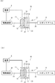
- (A), (B) is a conceptual diagram explaining the action
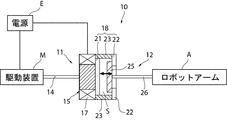
- FIG. 1 is a conceptual diagram showing a power transmission configuration including a torque limiter according to the first embodiment.
- the torque limiter 10 is provided between a driving device M such as a motor serving as a power source and a robot arm A that is operated by the power from the driving device M. From the driving device M to the robot arm Torque is transmitted to A, and when torque exceeding a torque limit value that is the upper limit value of the torque is applied, the torque transmission is interrupted.
- the torque limiter 10 includes an input unit 11 connected to a driving device M serving as an input side member and an output unit 12 connected to a robot arm A serving as an output side member. It consists of an electromagnetic friction clutch that transmits and shuts off torque between the input unit 11 and the output unit 12 by being separated and approached by the action and performing frictional coupling and separation thereof.
- the input unit 11 includes an input shaft 14 that is rotated by power from the driving device M, and a main body 15 that is fixed to the distal end side of the input shaft 14 and serves as a joint portion with the output unit 12 side.
- the main body 15 can be joined to the output unit 12 by using contact friction between the electromagnet 17 that enables adjustment of the magnetic force generated by adjusting the applied voltage supplied from the power source E and the output unit 12. And a joining portion 18 to be provided.
- the joint 18 is a disc-shaped first input plate 21 located on the electromagnet 17 side, and a donut plate shape that is disposed closer to the output unit 12 than the first input plate 21 and has a hole formed in the center.
- a moving space S of the output unit 12 is formed between the connecting member 23 and the connecting member 23.
- the output unit 12 connects the output plate 25 and the robot arm A to a disk-shaped output plate 25 movably disposed in the moving space S between the first and second input plates 21 and 22. And an output shaft 26 to be fixed.
- the output plate 25 is formed of a material that can be attracted to the first input plate 21 side by the magnetic force of the electromagnet 17, and is disposed so as to face the first and second input plates 21 and 22, respectively.
- the input plates 21 and 22 are allowed to move away from each other.
- the output plate 25 is in a state shown in FIG. 1 when it is not energized from the power source E to the electromagnet 17, that is, in a non-contact state with the first input plate 21, while the second plate It arrange
- a pressing means including a biasing member including a spring is provided between the input portion 11 and the output portion 12, and the pressing means connects the output plate 25 to the second plate. A force in the direction of approaching the input plate 22 is applied to the output plate 25.
- the first and second input plates 21 and 22 can utilize the contact friction with the output plate 25 to transmit torque from the input unit 11 to the output unit 12 by mutual contact.
- at least the contact surface with the output plate 25 is formed by a friction material that generates the contact friction force that enables the torque transmission.
- a friction material here, the thing of the property which does not prevent the effect
- the torque limiter 10 having the above configuration allows the output plate 25 to be separated and approached from the first and second input plates 21 and 22 by the magnetic force of the electromagnet 17 generated when power is supplied from the power source E, and is applied to the electromagnet 17.
- By changing the voltage it is possible to switch between these connected states by friction welding between the input unit 11 and the output unit 12 and the disconnected state of the input unit 11 and the output unit 12.
- the connection state when a torque equal to or less than the joining force, which is a contact friction force at that time, acts between the input unit 11 and the output unit 12, the input unit 11 and the output unit 12 are connected so as not to be relatively rotatable.
- the connected state is established, and the driving force from the driving device M is transmitted to the robot arm A.
- the input unit 11 and the output unit 12 can be rotated relative to each other. 11 idles and the driving force from the driving device M is not transmitted to the robot arm A. Therefore, the torque corresponding to the joining force becomes the torque limit value that is the upper limit value of the torque transmitted from the input unit 11 to the output unit 12.
- the torque limiter 10 is provided so that the torque limit value can be varied by changing the voltage applied to the electromagnet 17.
- the output plate 25 is not in contact with the first input plate 21 as shown in FIG.
- the connection state is in contact with the two input plates 22, and the torque transmission between the input unit 11 and the output unit 12 is enabled by the friction welding at this time.
- the electromagnet 17 is energized from this state, the output plate 25 is attracted to the first input plate 21 side by magnetic force, so that the joining force that is the contact friction force with the second input plate 22 is obtained.
- the distance gradually decreases, and then moves away from the second input plate 22 and then moves in the moving space S toward the first input plate 21.
- the output plate 25 is brought into non-contact with the first and second input plates 21 and 22 through the non-connection state of FIG. ),
- the second input plate 22 is brought into contact with the first input plate 21 while being in non-contact with the second input plate 22.
- the suction force to the first input plate 21 is increased, and the bonding force with the first input plate 21 is increased.
- the second input plate 22 has substantially the same outer diameter as the first input plate 21, but contacts the output plate 25 rather than the first input plate 21 due to the presence of the central hole. The area is getting smaller.
- the maximum torque limit value when the second input plate 22 and the output plate 25 are joined is the maximum when the first input plate 21 and the output plate 25 are in contact with each other due to the shape and the magnitude of the magnetic force that can be generated. It is set smaller than the torque limit value.
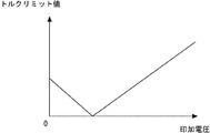
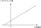
- the change characteristic of the torque limit value with respect to the applied voltage shown in FIG. 3 is obtained by the relative movement of the input unit 11 and the output unit 12 as described above.
- the output plate 25 comes into surface contact with the first input plate 21, and the input unit 11 and the output unit 12 are connected again.
- the suction force of the output plate 25 in the first input plate 21 is gradually increased to increase the joining force thereof, and the torque limit value is increased in proportion to the magnitude of the applied voltage. It will be.
- the magnetic force between them is adjusted with an applied voltage using an electromagnet or the like, and a connected state and a disconnected state that are not mutually connected
- the connected state is set when the applied voltage is zero, and the disconnected state is set at a predetermined value of the applied voltage, and the applied voltage is increased from the disconnected state.
- various structures and configurations can be adopted.
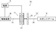
- the torque limiter 30 is characterized in that the input unit 11 and the output unit 12 are partially different from the torque limiter 10 of the first embodiment.
- the input unit 11 includes the input shaft 14 and an input plate 31 that is fixed to the distal end side of the input shaft 14 and serves as a joint portion with the output unit 12.
- the input plate 31 is composed of an electromagnet capable of changing the magnetic force generated according to the magnitude of the applied voltage from the power source E.
- the output unit 12 includes the output shaft 26 and a disk-shaped output plate 33 provided so as to be separated from and close to the input plate 31.
- the output plate 33 is made of a magnetic material such as a neodymium magnet.
- a pressing means for applying a pressing force in a direction in which the input plate 31 and the output plate 33 are brought into contact with each other is provided between the input unit 11 and the output unit 12.
- the pressing means as in the first embodiment, the input unit 11 and the output unit 12 are brought into the connected state with a certain fixed torque limit value even when no power is supplied.
- the pressing means is constituted by a biasing member including a spring that applies a force in a direction in which the output plate 33 is pressed against the input plate 31, and the input plate 31 and the output plate 33 using the pressing force at this time are configured. Enable to join by frictional force.
- the aforementioned friction material may be provided on at least one of the contact surfaces of the input plate 31 and the output plate 33. Further, without providing the friction material, or in combination with the friction material, when the input plate 31 and the output plate 33 are in contact with each other, an engagement member (not shown) that engages with each other so as to be relatively unrotatable is provided. Alternatively, a structure such as forming microscopic irregularities on the contact surfaces can be employed.
- the torque limiter 30 of the present embodiment operates as follows.
- the connection state is in contact with the input plate 31 and the output plate 33, and the input unit 11 and the output unit 12 are connected. Torque transmission between them.
- a positive voltage is applied to the input plate 31 from this state, the attractive force of the output plate 33 with respect to the input plate 31 increases due to the magnetic force, and the bonding force between the input plate 31 and the output plate 33 increases.
- the change characteristic of the torque limit value with respect to the applied voltage shown in FIG. 5 is obtained. That is, when the negative applied voltage to the input plate 31 is reduced from a predetermined negative applied voltage at which the input unit 11 and the output unit 12 are disconnected, the input unit 11 and the output unit are pressed by the pressing unit. As 12 becomes connected, the repulsive force of the output plate 33 with respect to the input plate 31 gradually decreases, and the torque limit value gradually increases. In addition, a certain torque limit value can be obtained even at the time of non-energization where the applied voltage becomes zero. When a positive voltage is applied to the input plate 31 from this non-energized state, the suction force of the output plate 33 to the input plate 31 gradually increases, and the torque limit value increases in proportion to the applied voltage. It will be.
- the action of the applied voltage “positive” or “negative” in the present embodiment is not limited, and the polarity may be reversed so that the same action and effect are generated.
- the attractive force can be generated with a negative applied voltage, while the repulsive force can be generated with a positive applied voltage.
- the torque limit value can be adjusted by adjusting the voltage applied to the input unit 11, but also the input unit so that a certain torque limit value can be obtained when de-energized. 11 and the output unit 12 can be secured. For this reason, the input unit 11 and the output unit 12 are not released from the connection state in the event of a power loss to the input unit 11 at the time of a power failure or an emergency stop, and the connection with a certain torque limit value is maintained. Will be. Therefore, at this time, the inertial movement of the robot arm A can be braked by using the stop of the driving device M due to power loss or the like, and unexpected collisions with people or objects around the robot arm A due to the inertial movement. Can be avoided and safety can be improved.
- connection structure by using an electromagnet or the like to adjust the magnetic force between them with the applied voltage, the connection state connected to each other and the non-connection state not connected to each other can be switched and separated and approached. Furthermore, when the applied voltage is zero, the connection state is established, the connection state is established with a predetermined applied voltage, and when the applied voltage is increased from the non-connection state, the connection state is established and the torque limit value is set. As long as it is a structure to raise, various things are employable.
- a power backup means that operates when the power supply E that supplies the applied voltage to the electromagnets 17 and 31 of the torque limiters 10 and 30 is cut off can be further provided.
- This power backup means is composed of a control circuit that is charged when the power source E is energized and that supplies the power to the electromagnets 17 and 31 in place of the power source E using the charged power when the power source E is shut off.
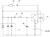
- the control circuit includes a diode 41, a resistor 42, a relay switch 43, a capacitor 44, a controller 45 that adjusts the voltage applied to the power source E, and the like.
- this control circuit power is supplied to the torque limiters 10 and 30 when energized, and a charging state using the capacitor 44 is established.
- the relay switch 43 is switched to the position indicated by the broken line in the figure, and power is supplied to the torque limiters 10 and 30 by using the charging of the capacitor 44.
- the input unit 11 and the output unit 12 are set to a higher torque limit value than when not energized.
- the robot arm A can be returned in a short time, and the robot arm A can continue to operate even if a power loss such as a power failure occurs.
- the torque limiter 10 according to the present invention is not limited to the application example in the above-described embodiment, but can be applied not only to robots having other configurations but also to general power transmission systems such as machines and devices.
- the components of the input unit 11 and the components of the output unit 12 in the aspect of each embodiment may be arranged in reverse between the input unit 11 and the output unit 12.
Landscapes
- Engineering & Computer Science (AREA)
- General Engineering & Computer Science (AREA)
- Mechanical Engineering (AREA)
- Robotics (AREA)
- Physics & Mathematics (AREA)
- Electromagnetism (AREA)
- One-Way And Automatic Clutches, And Combinations Of Different Clutches (AREA)
- Manipulator (AREA)
- Hydraulic Clutches, Magnetic Clutches, Fluid Clutches, And Fluid Joints (AREA)
Abstract
本発明のトルクリミッタ10は、入力側の駆動装置Mに繋がる入力部11と、出力側のロボットアームAに繋がる出力部12とを備えている。入力部11及び出力部12は、それらの間の磁力の調整によって相互に接続する接続状態と相互に接続していない非接続状態とを切り替え可能に離間接近する連結構造を有している。この連結構造は、印加電圧の調整により磁力の調整を可能にする電磁石17を含み、印加電圧がゼロのときに前記接続状態に設定されるとともに、所定の値の印加電圧で非接続状態とされ、当該非接続状態から印加電圧を増大すると接続状態となって入力部11及び出力部12の接合力が増大しトルクリミット値を上昇させる。
Description
本発明は、トルクリミッタに係り、更に詳しくは、入力側から出力側へ伝達されるトルクの上限値であるトルクリミット値を可変にするとともに、停電時等の不測の電源喪失や緊急停止時の際における安全性を考慮したトルクリミッタに関する。
従来、入力側から出力側に伝達されるトルクが所定値を超える過負荷状態になった場合に、当該トルクの伝達を遮断するトルクリミッタが知られている。このトルクリミッタとしては、例えば、特許文献1に開示されているように、通電による磁力を用いて入力側から出力側にトルクを伝達する電磁クラッチを用いたものがある。
ところで、ロボットと人間とが共生する環境下においては、当該環境に対するロボットの安全対策が重要になる。この安全対策として、ロボットが所望の動作を行っている最中に環境中の人間や物体に不意に衝突した場合等において、当該人間や物体に影響を与えないようにロボットを設計することが重要である。そこで、例えば、ロボットアームと当該ロボットアームを動作させるモータとの間にトルクリミッタを配置し、それらの間に過負荷が生じた際に、モータとロボットアームとのトルクの伝達を遮断する構成を設けることが考えられる。
しかしながら、前記特許文献1等の電磁クラッチを用いたトルクリミッタにあっては、非通電状態になると、電磁クラッチによる入力側から出力側の動力伝達が遮断されるため、停電時等の不測の電源喪失や緊急停止時に、安全性の低下を招く虞がある。つまり、例えば、入力側にモータを配置し、出力側にロボットアームを配置し、これらを電磁クラッチで連結する前述の構成の場合、電源喪失や緊急停止時に、モータとロボットアームが切り離されてしまう。その結果、ロボットアームは、それまでの動作による慣性で意図しない動きが行われたり、機器の重量による不意の落下を発生する等、安全性を低下させる事態が生じる虞がある。従って、電源喪失や緊急停止が発生したときには、ロボットアームの周囲の環境に対する安全性を考慮し、ロボットアームを瞬時に停止させる等の安全対策用の何等かの手段が別途必要になる。また、前記特許文献1のトルクリミッタでは、入力側から出力側へ伝達されるトルクの上限値であるトルクリミット値を可変にすることができないが、当該トルクリミット値を任意に変更できると、伝達トルク制御、安全性、直接教示等のための各種機能を実現可能になる。
本発明は、このような課題に着目して案出されたものであり、その目的は、入力側から出力側へのトルク伝達の際におけるトルクリミット値を可変にするとともに、停電時等の不測の電源喪失や緊急停止時の際における安全性を考慮したトルクリミッタを提供することにある。
前記目的を達成するため、主として、本発明は、入力側の部材から出力側の部材に伝達されるトルクの上限値となるトルクリミット値の大きさを電磁的に調整可能となるようにこれら部材の間に配置されるトルクリミッタにおいて、前記入力側の部材に繋がる入力部と、前記出力側の部材に繋がる出力部とを備え、前記入力部及び出力部は、それらの間の磁力の調整によって相互に接続する接続状態と相互に接続していない非接続状態とを切り替え可能に離間接近する連結構造を有し、前記連結構造は、印加電圧の調整により前記磁力の調整を可能にする電磁石を含み、前記印加電圧がゼロのときに前記接続状態に設定されるとともに、所定の値の前記印加電圧で前記非接続状態とされ、当該非接続状態から前記印加電圧を増大すると、前記接続状態となって前記入力部及び前記出力部の接合力が増大し、前記トルクリミット値を上昇させる、という構成を採っている。
本発明によれば、印加電圧の調整によってトルクリミット値を変化させることができ、ロボットを含む様々な機械要素に使用したときに、伝達トルク制御、安全性、直接教示等のための各種機能を実現することができる。また、印加電圧がゼロのときに、入力部と出力部の間で接続状態が確保され、動力等の入力側が非空転の状態となり、停電時等の不測の電源喪失や緊急停止時に、安全性を向上させることができる。つまり、電源で駆動する駆動装置を入力側に配置したような場合、電源喪失等により、駆動装置の駆動も停止するが、出力側が駆動装置に連結された状態となっているため、駆動装置の駆動抵抗を利用して出力側にブレーキをかけることができ、他の非常ブレーキ等の別途設ける構成を不要に、若しくは簡素化して、電源喪失等の不測の事態における周囲の安全性を確保することができる。
以下、本発明の実施形態について図面を参照しながら説明する。
(第1実施形態)
(第1実施形態)
図1には、第1実施形態に係るトルクリミッタを含む動力伝達構成を表す概念図が示されている。この図において、前記トルクリミッタ10は、一例として、動力源となるモータ等の駆動装置Mと、駆動装置Mからの動力によって動作するロボットアームAとの間に設けられ、駆動装置MからロボットアームAにトルクの伝達を行い、当該トルクの上限値となるトルクリミット値を超えるトルクが作用した場合に、前記トルクの伝達を遮断するように構成されている。
このトルクリミッタ10は、入力側の部材となる駆動装置Mに繋がる入力部11と、出力側の部材となるロボットアームAに繋がる出力部12とからなり、入力部11と出力部12を磁力の作用により離間接近し、それらの摩擦結合と離間を行うことで、入力部11と出力部12との間のトルクの伝達、遮断を行う電磁式摩擦クラッチからなる。
前記入力部11は、駆動装置Mからの動力によって回転する入力シャフト14と、当該入力シャフト14の先端側に固定され、出力部12側との接合部位となる本体15とからなる。
前記本体15は、電源Eから供給される印加電圧の調整により発生する磁力の調整を可能にする電磁石17と、出力部12との接触摩擦を利用して当該出力部12との接合を可能にする接合部18とを備えている。
前記接合部18は、電磁石17側に位置する円盤状の第1の入力プレート21と、第1の入力プレート21よりも出力部12寄りに配置され、中央に穴が形成されたドーナツ板状をなす第2の入力プレート22と、第1及び第2の入力プレート21,22をそれらの外周側で接続する円筒状の接続部材23とからなり、第1及び第2の入力プレート21,22と接続部材23との間に出力部12の移動空間Sが形成される。
前記出力部12は、第1及び第2の入力プレート21,22の間で移動空間S内を移動可能に配置された円盤状の出力プレート25と、出力プレート25とロボットアームAの間を連結固定する出力シャフト26とを備えている。
前記出力プレート25は、電磁石17の磁力によって第1の入力プレート21側に吸引可能な材質によって形成されており、第1及び第2の入力プレート21,22にそれぞれ対向するように配置され、これら入力プレート21,22に対して離間接近する方向への移動が許容されるようになっている。また、出力プレート25は、電源Eから電磁石17への通電が行われていない非通電時に、図1に示される状態で、すなわち、第1の入力プレート21に非接触となる一方、第2の入力プレート22に接触する状態で配置される。
なお、図示省略しているが、入力部11と出力部12の間には、ばねを含む付勢部材等からなる押付手段が設けられており、当該押付手段は、出力プレート25を第2の入力プレート22に接近させる方向の力を出力プレート25に付与するようになっている。
また、後述するように、第1及び第2の入力プレート21,22は、出力プレート25との接触摩擦を利用し、相互の接触による入力部11から出力部12へのトルク伝達が可能となるが、これら入力プレート21,22において、少なくとも出力プレート25との接触面は、前記トルク伝達を可能とする接触摩擦力を発生する摩擦材によって形成される。ここでの摩擦材としては、後述する入力部11及び出力部12の間での磁力の作用を阻止しない性質のものが用いられる。
以上の構成のトルクリミッタ10は、電源Eからの通電時に発生する電磁石17の磁力により、第1及び第2の入力プレート21,22に対する出力プレート25の離間接近が可能なり、電磁石17への印加電圧を変化させることによって、入力部11と出力部12との間での摩擦接合によるこれらの接続状態と、入力部11と出力部12の非接続状態との切り替えが可能となる。ここで、前記接続状態では、その際の接触摩擦力である接合力以下のトルクが入力部11及び出力部12の間に作用した場合、入力部11と出力部12とが相対回転不能に接続された接続状態となり、駆動装置Mからの駆動力がロボットアームAに伝達される。一方、前記接続状態で前記接合力を超えるトルクが入力部11及び出力部12の間に作用した場合、入力部11と出力部12とが相対回転可能となり、前記非接続状態と同様、入力部11が空転し、駆動装置Mからの駆動力がロボットアームAに伝達されなくなる。従って、前記接合力に相当するトルクが、入力部11から出力部12に伝達されるトルクの上限値となるトルクリミット値となる。
このトルクリミッタ10では、以下に詳述するように、電磁石17への印加電圧を変えることで、トルクリミット値が可変となるように設けられている。
このトルクリミッタ10では、以下に詳述するように、電磁石17への印加電圧を変えることで、トルクリミット値が可変となるように設けられている。
すなわち、先ず、電源Eから電磁石17への通電が行われていない非通電時においては、図1に示されるように、出力プレート25が、第1の入力プレート21に非接触となる一方、第2の入力プレート22に接触する前記接続状態となっており、このときの摩擦接合により、入力部11と出力部12の間でのトルク伝達が可能になる。この状態から、電磁石17への通電を行うと、出力プレート25が、磁力によって第1の入力プレート21側に吸引されることにより、第2の入力プレート22との接触摩擦力である接合力が徐々に低下し、図2(A)に示されるように、第2の入力プレート22から離れ、その後、移動空間S内を第1の入力プレート21に向かって移動する。このとき、印加電圧を増大することで、出力プレート25は、第1及び第2の入力プレート21,22に共に非接触となる同図(A)の前記非接続状態を経て、同図(B)に示されるように、第2の入力プレート22に非接触のまま第1の入力プレート21に接触して前記接続状態となる。そして、印加電圧を更に増大することで、第1の入力プレート21への吸引力が大きくなって、第1の入力プレート21との接合力が増大することになる。
なお、第2の入力プレート22は、第1の入力プレート21とほぼ同一の外径となっているが、中央の穴の存在によって、第1の入力プレート21よりも出力プレート25に対して接触面積が小さくなっている。当該形状や発生可能な磁力の大きさ等により、第2の入力プレート22と出力プレート25の接合時における最大のトルクリミット値は、第1の入力プレート21と出力プレート25の接触時における最大のトルクリミット値よりも小さく設定される。
このトルクリミッタ10によれば、以上のように入力部11と出力部12が相対移動することにより、図3に示される印加電圧に対するトルクリミット値の変化特性が得られる。
すなわち、電磁石17への非通電時である印加電圧がゼロのときには、第2の入力プレート22と出力プレート25との面接触により、入力部11と出力部12とが接続状態になり、ある程度のトルクリミット値が得られる。
そして、電磁石17への通電を開始し印加電圧を増大することで、出力プレート25が第1の入力プレート21側に吸引され、第2の入力プレート22との接合力が次第に弱まってトルクリミット値が徐々に減少していき、ある印加電圧の値で、出力プレート25が第2の入力プレート22より離れて入力部11と出力部12とが非接続状態になり、トルクリミット値がゼロとなる。
その後、印加電圧を更に増大することで、出力プレート25が第1の入力プレート21に面接触し、入力部11と出力部12とが再び接続状態となる。そして、印加電圧を更に増大すると、第1の入力プレート21における出力プレート25の吸引力が徐々に高まってそれらの接合力が増大し、印加電圧の大きさに比例してトルクリミット値が増大することになる。
そして、電磁石17への通電を開始し印加電圧を増大することで、出力プレート25が第1の入力プレート21側に吸引され、第2の入力プレート22との接合力が次第に弱まってトルクリミット値が徐々に減少していき、ある印加電圧の値で、出力プレート25が第2の入力プレート22より離れて入力部11と出力部12とが非接続状態になり、トルクリミット値がゼロとなる。
その後、印加電圧を更に増大することで、出力プレート25が第1の入力プレート21に面接触し、入力部11と出力部12とが再び接続状態となる。そして、印加電圧を更に増大すると、第1の入力プレート21における出力プレート25の吸引力が徐々に高まってそれらの接合力が増大し、印加電圧の大きさに比例してトルクリミット値が増大することになる。
なお、前記入力部11及び出力部12にあっては、電磁石等を用いてそれらの間の磁力を印加電圧で調整し、相互に接続する接続状態と相互に接続していない非接続状態とを切り替え可能に離間接近することで、印加電圧がゼロのときに前記接続状態に設定されるとともに、所定の値の印加電圧で前記非接続状態とされ、当該非接続状態から前記印加電圧を増大すると、前記接続状態となってトルクリミット値を上昇させる連結構造を有する限り、種々の構造や構成のものを採用することができる。
次に、本発明の他の実施形態について説明する。なお、以下の説明において、前記第1実施形態と同一若しくは同等の構成部分については同一符号を用いるものとし、説明を省略若しくは簡略にする。
(第2実施形態)
(第2実施形態)
本実施形態に係るトルクリミッタ30は、図4に示されるように、第1実施形態のトルクリミッタ10に対し、入力部11及び出力部12を一部異なる構成としたところに特徴を有する。
前記入力部11は、前記入力シャフト14と、入力シャフト14の先端側に固定されるとともに、出力部12との接合部位となる入力プレート31とを備えている。この入力プレート31は、電源Eからの印加電圧の大きさに応じて発生する磁力を変化可能な電磁石によって構成される。
前記出力部12は、前記出力シャフト26と、入力プレート31に対して離間接近可能に設けられた円盤状の出力プレート33とを備えている。この出力プレート33は、ネオジム磁石等の磁性体により形成されている。
また、図示省略しているが、入力部11及び出力部12の間には、入力プレート31と出力プレート33とを相互に接触させる方向の押付力を付与する押付手段が設けられており、当該押付手段により、前記第1実施形態と同様に、非通電時においても、ある程度の一定のトルクリミット値で入力部11及び出力部12を前記接続状態にするようになっている。
この押付手段としては、出力プレート33を入力プレート31に押し付ける方向への力を付与するばねを含む付勢部材等により構成し、この際の押付力を利用した入力プレート31と出力プレート33との摩擦力による接合を行えるようにする。ここで、当該摩擦力を調整するために、入力プレート31と出力プレート33の接触面の少なくとも一方に前述の摩擦材を設けても良い。また、当該摩擦材を設けずに、又は、当該摩擦材と併用して、入力プレート31と出力プレート33の接触時に、相対回転不能に相互に係合する係合部材(図示省略)を設け、又は、それらの接触面に微視的な凹凸を形成する等の構造を採用できる。
本実施形態のトルクリミッタ30は、次のように作動する。
先ず、電磁石からなる入力プレート31に電源Eから通電が行われていない非通電時においては、入力プレート31と出力プレート33に接触した前記接続状態となっており、入力部11と出力部12の間でのトルク伝達が可能になる。この状態から、入力プレート31に正電圧を印加すると、磁力によって入力プレート31に対する出力プレート33の吸引力が大きくなって、入力プレート31と出力プレート33の接合力が増大する。
一方、前記非通電時の状態から、入力プレート31に対して負電圧を印加すると、入力プレート31における磁石の極性が、正の印加電圧のときに対して反転し、入力プレート31に対する出力プレート33の反発力が発生する。このため、入力プレート31に印加される負の印加電圧を負方向に大きくする程、出力プレート33は、入力プレート31との接合力が次第に小さくなって、印加電圧が所定の負の値以上で、入力部11と出力部12とが図4の前記非接続状態となる。
以上のように入力部11と出力部12が相対移動することで、図5に示される印加電圧に対するトルクリミット値の変化特性が得られる。すなわち、入力部11と出力部12とが非接続状態とされる所定の負の値の印加電圧から、入力プレート31への負の印加電圧を小さくすると、前記押付手段によって入力部11と出力部12が接続状態になるともに、入力プレート31に対する出力プレート33の反発力が次第に小さくなり、トルクリミット値が次第に増大する。そして、印加電圧がゼロとなる非通電時においても、ある一定のトルクリミット値が得られることになる。そして、この非通電時の状態から、入力プレート31に対して正電圧を印加すると、入力プレート31への出力プレート33の吸引力が徐々に高まり、印加電圧に比例してトルクリミット値が増大することになる。
なお、本実施形態での印加電圧の「正」、「負」による作用は、限定的ではなく、当該極性を反転させて同様の作用効果を生じる設定としても良い。つまり、負の印加電圧で前記吸引力を発生させる一方、正の印加電圧で前記反発力を発生させることもできる。
以上の第1及び第2実施形態によれば、入力部11に対する印加電圧の調整によって、トルクリミット値を調整できるばかりか、非通電時において、ある一定のトルクリミット値が得られるように入力部11及び出力部12の接続状態を確保できる。このため、停電時等の入力部11への電源喪失や緊急停止時等の際に、入力部11及び出力部12は、それらの接続状態が解除されず、ある程度のトルクリミット値による接続が維持されることになる。従って、この際、電源喪失等による駆動装置Mの停止を利用し、ロボットアームAの慣性動作にブレーキをかけることができ、当該慣性動作によるロボットアームAの周囲の人や物に対する不意の衝突等を回避し、安全性を向上させることができる。
また、入力部11と出力部12とを磁力の作用にて摩擦結合する電磁式摩擦クラッチが用いられるため、高いトルク/質量比や停電時のバックドライバビリティを確保することができる。
なお、入力部11及び出力部12にあっては、前記各実施形態の態様に限定されるものではなく、前記各実施形態で採用した次の連結構造を有する限り、種々の構成を採用することができる。
すなわち、この連結構造としては、電磁石等を用いてそれらの間の磁力を印加電圧で調整することで、相互に接続する接続状態と相互に接続していない非接続状態とを切り替え可能に離間接近させ、更に、印加電圧がゼロのときに前記接続状態とし、所定の値の印加電圧で前記非接続状態とし、当該非接続状態から印加電圧を増大すると、前記接続状態となってトルクリミット値を上昇させる構造である限り、種々のものを採用することができる。
また、前記各実施形態に対し、トルクリミッタ10,30の電磁石17,31に印加電圧を供給する電源Eが遮断したときに作動する電源バックアップ手段を更に設けることができる。この電源バックアップ手段は、電源Eの通電時に充電され、電源Eの遮断時に、前記充電された電力を用い、電源Eに代わって電磁石17,31に電力供給を行う制御回路からなる。
前記制御回路は、図6に示されるように、ダイオード41、抵抗42、リレースイッチ43、コンデンサ44、電源Eの印加電圧を調整するコントローラ45等を含んで構成されている。すなわち、この制御回路では、通電時に、トルクリミッタ10,30への電力供給が行われるとともに、コンデンサ44を利用した充電状態となる。一方、電源Eが喪失すると、リレースイッチ43が同図中破線の位置に切り替わり、コンデンサ44での充電を利用して、トルクリミッタ10,30に電力供給が行われることになる。
この変形例によれば、停電時等の入力部11への電源喪失の際、その前の充電による電力を用い、入力部11及び出力部12を非通電時よりも高いトルクリミット値の状態に短時間で戻すことが可能になり、停電等の電源喪失が生じても、ロボットアームAの継続動作が可能になる。
なお、本発明におけるトルクリミッタ10は、前記実施形態における適用例に限らず、他の構成のロボットの他、機械や機器等の動力伝達系統全般に適用することができる。
また、は、前記各実施形態の態様における入力部11の構成要素と出力部12の構成要素について、前記入力部11及び前記出力部12との間で逆に配置することも可能である。
その他、本発明における装置各部の構成は図示構成例に限定されるものではなく、実質的に同様の作用を奏する限りにおいて、種々の変更が可能である。
10 トルクリミッタ
11 入力部
12 出力部
15 本体
17 電磁石
18 接合部
21 第1の入力プレート
22 第2の入力プレート
25 出力プレート
30 トルクリミッタ
31 入力プレート
33 出力プレート
A ロボットアーム(出力側の部材)
E 電源
M 駆動装置(入力側の部材)
S 移動空間
11 入力部
12 出力部
15 本体
17 電磁石
18 接合部
21 第1の入力プレート
22 第2の入力プレート
25 出力プレート
30 トルクリミッタ
31 入力プレート
33 出力プレート
A ロボットアーム(出力側の部材)
E 電源
M 駆動装置(入力側の部材)
S 移動空間
Claims (9)
- 入力側の部材から出力側の部材に伝達されるトルクの上限値となるトルクリミット値の大きさを電磁的に調整可能となるようにこれら部材の間に配置されるトルクリミッタにおいて、
前記入力側の部材に繋がる入力部と、前記出力側の部材に繋がる出力部とを備え、
前記入力部及び出力部は、それらの間の磁力の調整によって相互に接続する接続状態と相互に接続していない非接続状態とを切り替え可能に離間接近する連結構造を有し、
前記連結構造は、印加電圧の調整により前記磁力の調整を可能にする電磁石を含み、前記印加電圧がゼロのときに前記接続状態に設定されるとともに、所定の値の前記印加電圧で前記非接続状態とされ、当該非接続状態から前記印加電圧を増大すると、前記接続状態となって前記入力部及び前記出力部の接合力が増大し、前記トルクリミット値を上昇させることを特徴とするトルクリミッタ。 - 前記連結構造は、前記印加電圧をゼロから前記印加電圧を次第に増大させると、前記トルクリミット値が次第に低下して前記非接続状態になる構造に設けられることを特徴とする請求項1記載のトルクリミッタ。
- 前記連結構造は、前記印加電圧を所定の負の値にしたときに前記非接続状態となり、当該負の値からゼロに向かって前記印加電圧を変化させると、前記トルクリミット値が次第に上昇する構造に設けられることを特徴とする請求項1記載のトルクリミッタ。
- 入力側の部材から出力側の部材に伝達されるトルクの上限値となるトルクリミット値の大きさを電磁的に調整可能となるようにこれら部材の間に配置されるトルクリミッタにおいて、
前記入力側の部材に繋がる入力部と、前記出力側の部材に繋がる出力部とを備え、
前記入力部は、印加電圧の大きさに応じて発生する磁力を変化可能な電磁石と、前記出力部との接触摩擦によって当該出力部との接合を可能にする接合部とを備え、
前記接合部は、前記電磁石側に位置する第1の入力プレートと、当該第1の入力プレートよりも前記出力部寄りに配置される第2の入力プレートとを備え、
前記出力部は、前記磁力の変化によって前記第1及び第2の入力プレートの間で移動可能に配置される出力プレートを備え、
前記出力プレートは、前記印加電圧がゼロのときに、前記第2の入力プレートに接触して前記入力部及び前記出力部を相互に接続する接続状態とされ、前記印加電圧をゼロから増大させると、前記第2の入力プレートから離間して前記第1の入力プレート側に吸引され、前記第1の入力プレートにも接触しない非接続状態を経て、前記第1の入力プレートに接触して前記接続状態になるように設けられるとともに、前記第1の入力プレートとの接触時に、前記電磁石への印加電圧を増大させる程、前記第1の入力プレートとの接合力が増大して前記トルクリミット値を上昇させることを特徴とするトルクリミッタ。 - 前記入力部は、前記第2の入力プレート及び前記出力プレートの接触による前記接続状態での最大のトルクリミット値が、前記第1の入力プレート及び前記出力プレートの接触による前記接続状態よりも小さくなるように設定されることを特徴とする請求項4記載のトルクリミッタ。
- 入力側の部材から出力側の部材に伝達されるトルクの上限値となるトルクリミット値の大きさを電磁的に調整可能となるようにこれら部材の間に配置されるトルクリミッタにおいて、
前記入力側の部材に繋がる入力部と、前記出力側の部材に繋がる出力部とを備え、
前記入力部は、印加電圧の大きさに応じて発生する磁力を変化可能な電磁石からなる入力プレートを備え、
前記出力部は、前記入力プレートに対して離間接近可能な磁性体からなる出力プレートを備え、
前記入力プレート及び前記出力プレートは、前記印加電圧の極性を変化させることで、相互に反発して離間する方向に移動する状態と、相互に吸引して接近する方向に移動する状態とに変化可能に設けられるとともに、前記印加電圧がゼロのときに相互に接触して前記入力部及び前記出力部を相互に接続する接続状態とされることを特徴とするトルクリミッタ。 - 前記入力プレート及び前記出力プレートは、前記印加電圧の所定の負の値で相互に非接触となる非接続状態となり、当該非接続状態から正方向に前記印加電圧を変化させると、前記接続状態となってそれらの接合力が次第に増大し、前記トルクリミット値を上昇させることを特徴とする請求項6記載のトルクリミッタ。
- 前記入力部と前記出力部の間には、前記印加電圧がゼロのときに、前記入力プレートと前記出力プレートとを相互に接触させる押付力を付与する押付手段が設けられていることを特徴とする請求項6記載のトルクリミッタ。
- 前記印加電圧を前記電磁石に供給する電源が遮断したときに作動する電源バックアップ手段を更に設け、
前記電源バックアップ手段は、前記電源の通電時に充電され、前記電源の遮断時に、前記充電された電力を用い、前記電源に代わって前記電磁石に電力供給を行う制御回路からなることを特徴とする請求項1記載のトルクリミッタ。
Priority Applications (2)
| Application Number | Priority Date | Filing Date | Title |
|---|---|---|---|
| US16/495,204 US11118634B2 (en) | 2017-03-19 | 2018-02-24 | Torque limiter |
| CN201880031588.3A CN110637170B (zh) | 2017-03-19 | 2018-02-24 | 扭矩限制器 |
Applications Claiming Priority (2)
| Application Number | Priority Date | Filing Date | Title |
|---|---|---|---|
| JP2017053823A JP6866981B2 (ja) | 2017-03-19 | 2017-03-19 | トルクリミッタ |
| JP2017-053823 | 2017-03-19 |
Publications (1)
| Publication Number | Publication Date |
|---|---|
| WO2018173633A1 true WO2018173633A1 (ja) | 2018-09-27 |
Family
ID=63584523
Family Applications (1)
| Application Number | Title | Priority Date | Filing Date |
|---|---|---|---|
| PCT/JP2018/006833 Ceased WO2018173633A1 (ja) | 2017-03-19 | 2018-02-24 | トルクリミッタ |
Country Status (4)
| Country | Link |
|---|---|
| US (1) | US11118634B2 (ja) |
| JP (1) | JP6866981B2 (ja) |
| CN (1) | CN110637170B (ja) |
| WO (1) | WO2018173633A1 (ja) |
Families Citing this family (2)
| Publication number | Priority date | Publication date | Assignee | Title |
|---|---|---|---|---|
| EP3865725B1 (en) * | 2020-02-17 | 2024-03-27 | Ratier-Figeac SAS | Torque limiter |
| JP2025012364A (ja) * | 2023-07-13 | 2025-01-24 | Tdk株式会社 | 触覚伝達装置及び触覚伝達方法 |
Citations (9)
| Publication number | Priority date | Publication date | Assignee | Title |
|---|---|---|---|---|
| JPS5419045A (en) * | 1977-07-13 | 1979-02-13 | Mitsubishi Electric Corp | Friction system coupling device |
| JPS645973Y2 (ja) * | 1982-01-28 | 1989-02-15 | ||
| JPH01303326A (ja) * | 1988-05-31 | 1989-12-07 | Teijin Ltd | 巻取装置 |
| JPH0249852A (ja) * | 1988-08-11 | 1990-02-20 | Chieo Matsuura | 玄関上がり框下回転収納庫。 |
| JPH11247880A (ja) * | 1998-02-27 | 1999-09-14 | Canon Inc | トルクリミッタ及びシート給送装置及び画像処理装置 |
| JP2002086379A (ja) * | 2000-09-13 | 2002-03-26 | Toshiba Corp | ロボット、ロボットの制御方法およびロボットを動作するプログラムを記憶したコンピュータ読み取り可能な記憶媒体 |
| JP2007187283A (ja) * | 2006-01-16 | 2007-07-26 | Shinko Electric Co Ltd | 電磁クラッチ |
| JP2013076432A (ja) * | 2011-09-29 | 2013-04-25 | Nikon Corp | トルク制限機構、駆動装置及びロボット装置 |
| JP2015085390A (ja) * | 2013-10-28 | 2015-05-07 | 株式会社アイエイアイ | アクチュエータ装置 |
Family Cites Families (14)
| Publication number | Priority date | Publication date | Assignee | Title |
|---|---|---|---|---|
| US2547137A (en) * | 1948-12-06 | 1951-04-03 | Bendix Aviat Corp | Electromagnet overload release clutch |
| US2966977A (en) * | 1957-10-17 | 1961-01-03 | Lear Inc | Overload limiting clutch |
| US3455421A (en) * | 1967-06-12 | 1969-07-15 | Bendix Corp | Stationary field clutch |
| US4397380A (en) * | 1981-09-08 | 1983-08-09 | Canadian Fram Limited | Fail safe electromagnetic clutch |
| JPH048834U (ja) * | 1990-05-15 | 1992-01-27 | ||
| JP4138913B2 (ja) * | 1997-09-05 | 2008-08-27 | 勝行 戸津 | 電動回転工具およびねじ具の締付けトルク管理システム |
| JP2001003951A (ja) * | 1999-06-23 | 2001-01-09 | Kansai Tlo Kk | 力制限装置、トルクリミッタ、ロボットアーム、及びロボット |
| JP5550043B2 (ja) * | 2009-04-23 | 2014-07-16 | シンフォニアマイクロテック株式会社 | 電磁クラッチ |
| JP2013234699A (ja) * | 2012-05-08 | 2013-11-21 | Prospine:Kk | 磁気カップリング装置 |
| DE102014103837B4 (de) * | 2014-03-20 | 2015-12-17 | Kendrion (Villingen) Gmbh | Elektromagnetische Brems- oder Kupplungseinrichtung mit Dämpfungsmitteln zur verbesserten Geräuschreduzierung |
| JP6217499B2 (ja) | 2014-04-07 | 2017-10-25 | 株式会社デンソー | トルクリミッタ付き回転機器 |
| JP6649274B2 (ja) * | 2014-04-30 | 2020-02-19 | エフピーティー インダストリアル ソチエタ ペル アツィオーニ | 熱機関の冷却流体を再循環させるポンプアセンブリ |
| FR3022526B1 (fr) * | 2014-06-20 | 2016-06-24 | Sagem Defense Securite | Actionneur electromecanique a limiteur de couple magnetique |
| JP6699843B2 (ja) * | 2015-07-04 | 2020-05-27 | 学校法人早稲田大学 | ロボットアームの制御システム |
-
2017
- 2017-03-19 JP JP2017053823A patent/JP6866981B2/ja active Active
-
2018
- 2018-02-24 WO PCT/JP2018/006833 patent/WO2018173633A1/ja not_active Ceased
- 2018-02-24 US US16/495,204 patent/US11118634B2/en active Active
- 2018-02-24 CN CN201880031588.3A patent/CN110637170B/zh active Active
Patent Citations (9)
| Publication number | Priority date | Publication date | Assignee | Title |
|---|---|---|---|---|
| JPS5419045A (en) * | 1977-07-13 | 1979-02-13 | Mitsubishi Electric Corp | Friction system coupling device |
| JPS645973Y2 (ja) * | 1982-01-28 | 1989-02-15 | ||
| JPH01303326A (ja) * | 1988-05-31 | 1989-12-07 | Teijin Ltd | 巻取装置 |
| JPH0249852A (ja) * | 1988-08-11 | 1990-02-20 | Chieo Matsuura | 玄関上がり框下回転収納庫。 |
| JPH11247880A (ja) * | 1998-02-27 | 1999-09-14 | Canon Inc | トルクリミッタ及びシート給送装置及び画像処理装置 |
| JP2002086379A (ja) * | 2000-09-13 | 2002-03-26 | Toshiba Corp | ロボット、ロボットの制御方法およびロボットを動作するプログラムを記憶したコンピュータ読み取り可能な記憶媒体 |
| JP2007187283A (ja) * | 2006-01-16 | 2007-07-26 | Shinko Electric Co Ltd | 電磁クラッチ |
| JP2013076432A (ja) * | 2011-09-29 | 2013-04-25 | Nikon Corp | トルク制限機構、駆動装置及びロボット装置 |
| JP2015085390A (ja) * | 2013-10-28 | 2015-05-07 | 株式会社アイエイアイ | アクチュエータ装置 |
Also Published As
| Publication number | Publication date |
|---|---|
| JP6866981B2 (ja) | 2021-04-28 |
| US20200025258A1 (en) | 2020-01-23 |
| US11118634B2 (en) | 2021-09-14 |
| JP2018155360A (ja) | 2018-10-04 |
| CN110637170A (zh) | 2019-12-31 |
| CN110637170B (zh) | 2021-12-14 |
Similar Documents
| Publication | Publication Date | Title |
|---|---|---|
| CN109328272B (zh) | 用于磁流变流体致动器单元的多模式控制系统 | |
| CN108603549B (zh) | 用于工业机器人的多盘式制动器和包括多盘式制动器的工业机器人 | |
| CN102852996B (zh) | 电磁接合装置 | |
| US10384535B2 (en) | Drive unit | |
| JP7033213B2 (ja) | 噛み合い電磁クラッチ | |
| US7726455B2 (en) | Electro-mechanical clutch | |
| JP5935906B2 (ja) | 断接機構 | |
| US20090294238A1 (en) | Electromechanical actuator for friction clutches | |
| WO2018173633A1 (ja) | トルクリミッタ | |
| JP2009041654A (ja) | ブレーキの制御装置 | |
| JP2021175917A (ja) | ロボットおよび他の用途のためのフェイルセーフブレーキ装置 | |
| EP2786054B1 (en) | Failsafe apparatus for use with linear actuators | |
| WO2025246148A1 (zh) | 一种自锁式联接器、差速器总成及差速器总成控制方法 | |
| JPWO2022209678A5 (ja) | ||
| CN108025640A (zh) | 用于致动离合器的系统 | |
| KR101786219B1 (ko) | 더블 클러치조립체 및 그의 브레이크기구 | |
| JPS6248100B2 (ja) | ||
| JP2018096524A5 (ja) | ||
| JP2006349109A (ja) | 回転伝達装置 | |
| JP2012122563A (ja) | 係合装置 | |
| JP2010014153A (ja) | 電磁連結装置 | |
| GB665602A (en) | Clutch device for transmitting rotary movement | |
| JP2012149724A (ja) | 動力断続装置 | |
| JP2008144948A (ja) | 回転伝達装置 | |
| JP2006349128A (ja) | 回転伝達装置 |
Legal Events
| Date | Code | Title | Description |
|---|---|---|---|
| 121 | Ep: the epo has been informed by wipo that ep was designated in this application |
Ref document number: 18770622 Country of ref document: EP Kind code of ref document: A1 |
|
| NENP | Non-entry into the national phase |
Ref country code: DE |
|
| 122 | Ep: pct application non-entry in european phase |
Ref document number: 18770622 Country of ref document: EP Kind code of ref document: A1 |