WO2018173548A1 - 内燃機関のピストン及びその製造方法 - Google Patents
内燃機関のピストン及びその製造方法 Download PDFInfo
- Publication number
- WO2018173548A1 WO2018173548A1 PCT/JP2018/004976 JP2018004976W WO2018173548A1 WO 2018173548 A1 WO2018173548 A1 WO 2018173548A1 JP 2018004976 W JP2018004976 W JP 2018004976W WO 2018173548 A1 WO2018173548 A1 WO 2018173548A1
- Authority
- WO
- WIPO (PCT)
- Prior art keywords
- binder
- piston
- functional
- combustion engine
- internal combustion
- Prior art date
- Legal status (The legal status is an assumption and is not a legal conclusion. Google has not performed a legal analysis and makes no representation as to the accuracy of the status listed.)
- Ceased
Links
Images






Definitions
- the present invention relates to a piston for an internal combustion engine and a method for manufacturing the same.
- Patent Document 1 As a piston of a conventional internal combustion engine, for example, one described in Patent Document 1 below is known.
- the piston of this internal combustion engine is provided with two functional layers (first functional layer and second functional layer) having different heat capacities formed of metal materials having different main components adjacent to each other at the crown.
- the present invention has been devised in view of the technical problem of the piston of the conventional internal combustion engine, and is an internal combustion engine that can obtain good joining characteristics at the boundary between two adjacent functional layers. It aims at providing a piston and its manufacturing method.
- the piston of the internal combustion engine according to the present invention includes, as an aspect thereof, a material having a lower heat conductivity and a higher specific heat capacity than the metal material of the main body portion in the functional layer holding portion formed on the crown surface of the piston head.
- a first functional layer formed by mixing a first functional material and a first binder made of a metal material that holds the first functional material, and a material having a lower thermal conductivity and a smaller specific heat capacity than the main body.
- an arrangement in which a mixed material of the first functional material and the first binder, and a mixed material of the second functional material and the second binder are arranged in the functional layer holding portion. It is desirable that the manufacturing process includes a step, and a bonding step of bonding the mixed material of the first functional material and the first binder and the mixed material of the second functional material and the second binder to the functional layer holding portion.
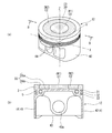
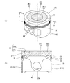
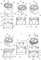
- FIG. 2A and 2B are views showing a single piston shown in FIG. 1, wherein FIG. 2A is a perspective view, and FIG. 2B is a cross-sectional view taken along the line AA in FIG.
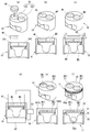
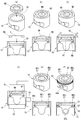
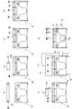
- FIG. 3 is a cross-sectional view showing a manufacturing method of the piston shown in FIG. 2, in which (a) to (c) are placement steps, (d) and (e) are joining steps, and (f) is a cross-sectional view showing machining steps. .
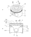
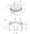
- FIG. 5A and 5B are views showing a single piston shown in FIG. 4, wherein FIG. 5A is a perspective view, and FIG. 5B is a cross-sectional view taken along the line BB of FIG.
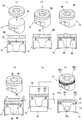
- FIG. 6 is a cross-sectional view showing a manufacturing method of the piston shown in FIG. 5, wherein (a) to (c) are an arrangement step, (d) and (e) are joining steps, and (f) is a cross-sectional view showing a machining step. .
- FIG. 10 is a cross-sectional view showing a manufacturing method of the piston shown in FIG. 9, in which (a) to (c) are placement steps, (d) and (e) are joining steps, and (f) is a cross-sectional view showing machining steps.
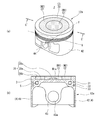
- 4A and 4B are views showing a piston of an internal combustion engine according to a third embodiment of the present invention, in which FIG. 5A is a perspective view, and FIG. 5B is a cross-sectional view taken along line EE of FIG. FIGS.
- FIGS. 11A to 11D are an arrangement step
- FIG. 11E is a joining step
- FIG. It is a figure which shows the piston of the internal combustion engine which concerns on 4th Embodiment of this invention, Comprising: (a) is a perspective view, (b) is the FF sectional view taken on the line of the same figure (a).
- FIG. 14 is a cross-sectional view showing a method for manufacturing the piston shown in FIG. 13, wherein (a) to (d) are placement steps, (e) is a joining step, and (f) is a cross-sectional view showing a machining step.
- FIG. 16 is a cross-sectional view showing a manufacturing method of the piston shown in FIG. 15, wherein (a) to (e) are a placement step, (f) is a joining step, and (g) is a cross-sectional view showing a machining step.
- the axis parallel to the moving direction of the piston is Z
- the axis parallel to the central axis of the first pin hole 43a and the second pin hole 44a is Y
- both the axes Z, Y A description will be given assuming that the orthogonal axis is X.
- a direction parallel to the piston axis Z is referred to as an “axial direction”
- a direction around the piston axis Z is referred to as a “circumferential direction”.
- First Embodiment 1 to 3 show a first embodiment of a piston according to the present invention.
- the piston of the internal combustion engine and the manufacturing method thereof according to the present invention are applied to a so-called side injection type engine.
- FIG. 1 shows a cross-sectional view along the axial direction of a predetermined cylinder 20 in the cylinder block 21 of the engine EG1.
- the piston 11 is formed in a substantially covered cylindrical shape by casting a predetermined metal material, for example, an Al—Si based aluminum alloy material (AC8A or the like).
- the piston 11 is provided so as to be movable (slidable) along the axial direction in a cylinder 20 that is formed through the cylinder block 21 of the engine EG1 that is an internal combustion engine.
- a combustion chamber C is formed in 20.
- reference numeral 22 denotes a cylinder head placed on the cylinder block 21. Inside the cylinder head 22, an intake valve 23 is provided so as to be able to open and close an intake port 22 a for introducing an air-fuel mixture into the combustion chamber C, and an exhaust valve 24 is an exhaust port 22 b for exhausting the gas in the combustion chamber C. Is provided so that it can be opened and closed.
- the engine EG1 has a so-called side injection system, and an injector 25, which is a fuel injection valve, is disposed on the cylinder head 22 so as to face the outer peripheral side of the combustion chamber C, so that it faces almost the center position of the combustion chamber C.
- a spark plug 26 is disposed on the front side.
- FIG. 2 shows the single piston 11 shown in FIG. 1, (a) is a perspective view of the piston 11 seen obliquely from above (the crown surface 30 side), and (b) is a line AA in FIG. The longitudinal cross-sectional view of the piston 11 cut
- the piston 11 includes a piston head 3 that is a crown portion that forms a combustion chamber C in the cylinder 20, a cylindrical portion 4 that extends on the opposite side in the axial direction with respect to the piston head 3,
- the piston head 3 and the cylinder portion 4 constitute a main body portion according to the present invention.
- the piston head 3 has a substantially flat crown surface 30 facing the combustion chamber C in the cylinder 20.
- the crown surface 30 is provided with a heat insulating coating layer C1 corresponding to the first functional layer of the present invention in a region on the intake side where fuel is injected from the injector 25, and is cooled by the heat insulating coating layer C1. Loss is suppressed.
- a thermal barrier coating layer C2 corresponding to the second functional layer is provided in a region on the exhaust side that is symmetrical to the injector 25 with respect to the axis Z on the crown surface 30, and knocking is suppressed by the thermal barrier coating layer C2. is doing.
- the heat insulating coating layer C1 and the thermal barrier coating layer C2 are provided adjacent to each other, and are provided in such a manner that a part of the outer peripheral side is directly joined.
- the heat insulating coating layer C1 is formed on the first functional layer holding portion 341 formed in the region on the intake side of the functional layer holding portion 34 formed concavely on the crown surface 30 on the crown surface 30 and the first functional material.
- the heat insulating material M1 formed by mixing the first binder is filled, and the heat insulating material M1 is formed by sintering by a pulse current method described later.
- the first functional layer holding portion 341 has a substantially circular concave shape having a constant depth in the entire region, and is held as a concave portion 341a formed in the crown surface 30 and a peripheral wall formed so as to surround the concave portion 341a. And a wall 341b.
- the first functional material a material having a lower thermal conductivity and a higher specific heat capacity than a metal material (in this embodiment, an aluminum alloy material) constituting the main body, for example, zirconia is used.
- a metal material that holds zirconia as the first functional material for example, pure aluminum is used for the first binder.
- the thermal barrier material M2 formed by mixing the second functional material and the second binder is mixed with the second functional layer holder 342 formed in the exhaust side region of the functional layer holder 34.
- the heat shielding material M2 is filled and sintered by a pulse energization method described later.
- the second functional layer holding portion 342 Similar to the first functional layer holding portion 341, the second functional layer holding portion 342 has a substantially circular concave shape having a constant depth in the entire area thereof, and a concave portion 342a formed on the crown surface 30 and the concave portion 342a. And a holding wall 342b as a peripheral wall formed so as to surround.
- the second functional material a material having a lower thermal conductivity and a smaller specific heat capacity than the metal material (the aluminum alloy material in the present embodiment) constituting the main body, for example, porous silica is used.
- the second binder is a metal material that holds porous silica as the second functional material, and the main component is the same as the main component of the first binder, for example, pure aluminum.
- the main component of the first binder forming the heat insulation coating layer C1 and the main component of the second binder forming the thermal barrier coating layer C2 are the same metal material” is based on the following definition. .
- the metal material that is the main component of the first binder includes the metal material that is the main component of the second binder and ISO (International Organization for Standardization), JIS (Japan Industrial Standards), AISI ( American Iron and Steel Institute (American Iron and Steel Institute), BS (British Standards: British Standards Association) or DIN (Deutsche Norman: German Industrial Standard) is a metal material classified as the same metal material.
- ISO International Organization for Standardization
- JIS Joint Industrial Standards
- AISI American Iron and Steel Institute
- BS British Standards: British Standards Association
- DIN Deutsche Norman: German Industrial Standard
- the metal material and the metal material as the main component of the second binder include the metal material of the main body part and ISO (International Organization for Standardization), JIS (Japanese Industrial Standards), AISI (American Iron and Steel Institute), BS (British Standards Institute) or DIN.
- ISO International Organization for Standardization
- JIS Japanese Industrial Standards
- AISI American Iron and Steel Institute
- BS British Standards Institute
- DIN DIN.
- the bottom surface of the heat insulating coating layer C1 is bonded to the concave portion 341a of the first functional layer holding portion 341, and a part of the outer peripheral side is attached to the holding wall 341b of the first functional layer holding portion 341.
- the remaining portions on the outer peripheral side are respectively joined to the outer peripheral surface of the thermal barrier coating layer C2.
- the bottom surface of the thermal barrier coating layer C2 is bonded to the concave portion 342a of the second functional layer holding portion 342, and a part of the outer peripheral side is attached to the holding wall 342b of the second functional layer holding portion 342 and the outer peripheral side.
- the remaining portions are respectively joined to the outer peripheral surface of the heat insulating coating layer C1.
- three ring grooves 31 to 33 each having a substantially rectangular cross section are formed in an annular shape along the circumferential direction.
- the ring grooves 31 to 33 are fitted with three substantially annular piston rings R1 to R3 extending in the circumferential direction (see FIG. 1), whereby the combustion chamber C is hermetically sealed by the piston rings R1 to R3. Is sealed.
- a cooling channel 5 which is a passage through which oil as a fluid for cooling the piston head 3 flows, is formed in a substantially annular shape inside the piston head 3 so as to extend in the circumferential direction.
- the cooling channel 5 is configured to be able to communicate with the outside through a plurality of communication holes (not shown) that open to the opposite side of the crown surface 30 in the axial direction.
- oil sprayed from an oil jet device (not shown) from the cylinder portion 4 side of the piston 11 is introduced into the cooling channel 5 through some of the plurality of through holes, and the remaining penetrations. Oil in the cooling channel 5 is discharged through the hole.
- the cylindrical portion 4 is provided with a pair of skirt portions 41, 42 formed so as to be slidable with respect to the peripheral wall of the cylinder 20, and substantially two-sided widths on both ends in the circumferential direction of the pair of skirt portions 41, 42.
- a pair of pin boss portions 43 and 44 for supporting a piston pin are integrally formed in a substantially cylindrical shape so as to be continuous in the circumferential direction.
- the pair of skirt portions 41 and 42 is configured by a first skirt portion 41 and a second skirt portion 42 that are disposed to face each other in the axis X direction.
- the pair of pin boss portions 43, 44 is configured by a first pin boss portion 43 and a second pin boss portion 44 that are arranged to face each other in the direction of the axis Y. From the first skirt portion 41 and the second skirt portion 42, Is also formed thick.
- first pin boss portion 43 and the second pin boss portion 44 have a first pin hole 43a and a second pin hole 44a which are a pair of pin holes for supporting the end portions of the piston pins (not shown). A penetration is formed along the direction. That is, one end of the piston pin (not shown) is inserted and supported in the first pin hole 43a, and the other end of the piston pin (not shown) is inserted and supported in the second pin hole 44a. It has become so.
- FIG. 3 is a longitudinal sectional view of the piston material 10 for explaining the manufacturing method of the piston 11, wherein (a) to (c) are placement steps, (d) and (e) are joining steps, and (f) is machining. The process is shown.
- a heat insulating material M1 obtained by mixing the first functional material and the first binder is preformed in a so-called tablet shape as a cylindrical sintered body. (Preform molding process).
- preform molding process it is desirable to preform at least one of the heat insulating material M1 or the heat shielding material M2 before the arrangement step described later.
- the sintered body of the preliminarily formed heat insulating material M1 is fitted into the first functional layer holding portion 341, and then FIG. ),
- the second functional layer holding part 342 is filled with the powder of the heat shielding material M2 formed by mixing the second functional material and the second binder (arrangement step).
- the powder of the heat shielding material M2 is filled more than the volume of the second functional layer holding part 342, and as shown in FIG.
- the surplus heat insulating material M2 is removed by squeegee 60, so that the entire second functional layer holding portion 342 is filled without excess or deficiency.
- a heat insulating material M1 that is a mixed material of the first functional material and the first binder, and a heat shielding material M2 that is a mixed material of the second functional material and the second binder are bonded to the functional layer holding portions 341 and 342 (bonding step).
- the regions filled with the heat insulating material M1 and the heat shielding material M2 are divided into a first electrode 61 and a second electrode made of carbon electrodes connected to a pulse power source 63, respectively, as shown in FIG. Sintering is performed by sandwiching the electrode 62 and applying a pulse current while heating both the materials M1 and M2 and heating them.
- the first electrode 61 has a convex shape that can be fitted into the first functional layer holding part 341 and the second functional layer holding part 342, and is pressed by the convex first electrode 61.
- the heat insulating coating layer C ⁇ b> 1 and the thermal barrier coating layer C ⁇ b> 2 are formed in a concave shape corresponding to the convex shape of the first electrode 61.
- the retaining walls 341b and 342b of the portion 342 are cut to form the crown surface 30 smoothly (machining process). Further, in this machining step, the ring grooves 31 to 33 and the first pins are combined with the cutting of the holding walls 341b and 342b of the first functional layer holding portion 341 and the second functional layer holding portion 342.
- the piston 11 is completed by forming the hole 43a and the second pin hole 44a.
- a heat insulating coating layer that is a first functional layer and a thermal barrier coating layer that is a second functional layer are disposed adjacent to each other. Sometimes it is desirable.
- the heat insulating coating layer and the thermal barrier coating layer are formed of metal materials having different main components as in the conventional piston, good bonding characteristics cannot be obtained at the boundary between the two coating layers. There was a risk of lowering the durability of the piston.
- the piston 11 according to the present embodiment is a piston of an internal combustion engine and is formed of a metal material (aluminum alloy material in the present embodiment), and the piston head 3 and a skirt portion provided in the piston head 3. And a functional layer provided on the crown surface 30 which is the surface of the piston head 3 on the combustion chamber C side of the engine EG1 which is an internal combustion engine.
- a first functional layer provided in the holding part 34 and the functional layer holding part 34 including a first functional material and a first binder, the first functional material being a main body part A material having a lower thermal conductivity and a larger specific heat capacity (zirconia in the present embodiment) than that of the metal material, and the first binder is a metal material binder (pure aluminum in the present embodiment) holding the first functional material.
- a functional layer including a second functional material and a second binder and the second functional material is a material (porous silica in this embodiment) having a lower thermal conductivity and a smaller specific heat capacity than the main body.
- the second binder is a binder of a metal material that holds the second functional material, the main component of which is the same metal material as the main component of the first binder (pure aluminum in this embodiment),
- the second binder is mixed, and has a thermal barrier coating layer C2 as a second functional layer provided adjacent to the first functional layer.
- the heat insulating coating layer C1 and the thermal barrier coating layer C2 are provided adjacent to each other on the crown surface 30. For this reason, the layout property of the plurality of coating layers C1 and C2 can be improved.
- the adjacent coating layers C1 and C2 are each formed of the same metal material with the main component of the binder. For this reason, the familiarity of both coating layers C1 and C2 is good, and the boundary part with the favorable joining characteristic by the said adjacent coating layers C1 and C2 can be obtained.
- the piston 11 is manufactured by a method of manufacturing a piston for an internal combustion engine, and the piston 11 includes a piston head 3 and a first skirt portion 41 and a second skirt portion which are skirt portions provided on the piston head 3. 42 and provided on a crown surface 30 which is a surface on the combustion chamber C side of the engine EG1 which is an internal combustion engine of the piston head 3 and a main body portion made of a metal material (in this embodiment, an aluminum alloy material).
- a metal material in this embodiment, an aluminum alloy material
- Functional layer holding part 34, heat insulating coating layer C1 as the first functional layer and thermal barrier coating layer as the second functional layer provided adjacent to functional layer holding part 34 (first functional layer holding part 341) C2 and the heat insulating coating layer C1 includes a first functional material and a first binder, and the first functional material has a lower thermal conductivity and a larger specific heat capacity than the metal material of the main body ( This embodiment Zirconia), the first binder is a metallic material binder (pure aluminum in this embodiment) that holds the first functional material, and the thermal barrier coating C2 includes the second functional material, the second binder,
- the second functional material is a material (porous silica in this embodiment) having a lower thermal conductivity and a smaller specific heat capacity than the main body, and the second binder is a metal material that holds the second functional material
- the main component is the same metal material as the main component of the first binder (pure aluminum in this embodiment), the first functional material and the first binder mixed material, the second functional material and the second material.
- An arrangement step of arranging the mixed material of the binder in the functional layer holding unit 34 (the first functional layer holding unit 341 and the second functional layer holding unit 342), the mixed material of the first functional material and the first binder,
- the functional layer holding part 34 It is desirable to perform the method of manufacturing a piston for an internal combustion engine having a bonding step of bonding the first functional layer holding portion 341 and the second functional layer holding portion 342), the.
- the heat insulating coating layer C1 and the thermal barrier coating layer C2 are provided adjacent to each other on the crown surface 30. For this reason, the layout property of the plurality of coating layers C1 and C2 can be improved.
- the adjacent coating layers C1 and C2 are each formed of the same metal material with the same main component of the binder. For this reason, the familiarity of both coating layers C1 and C2 is good, and the boundary part with the favorable joining characteristic by the said adjacent coating layers C1 and C2 can be obtained.
- the metal material that is the main component of the first binder is a metal material that is classified as the same metal material in ISO, JIS, AISI, BS, or DIN as the metal material that is the main component of the second binder. Material.
- the metal material that is the main component of the first binder and the metal material that is the main component of the second binder are classified into the same type of metal according to the standardization mechanism, industrial standards, and the like. ing. For this reason, the familiarity of the adjacent heat-insulating coating layer C1 and the thermal barrier coating layer C2 is good, and good bonding characteristics can be obtained at the boundary between these coating layers C1 and C2.
- the metal material of the main component of the first binder and the metal material of the main component of the second binder are the same as the metal material of the main component of the main body in ISO, JIS, AISI, BS, or DIN. It is a metal material classified as a metal material.
- the metal material that is the main component of the first binder and the metal material that is the main component of the second binder are the metal material that is the main component of the main body, the standardization mechanism, and the industry standard. It is classified into the same kind of metal. For this reason, familiarity with the adjacent heat insulation coating layer C1 and thermal insulation coating layer C2 and the functional layer holding part 34 (the 1st functional layer holding part 341 and the 2nd functional layer holding part 342) of a main-body part is good, and both said coating films Good bonding characteristics can be obtained at the boundary between the layers C1 and C2 and the functional layer holding part 34 (the first functional layer holding part 341 and the second functional layer holding part 342) of the main body.
- the joining process functions in the same process for the mixed material of the first functional material and the first binder and the mixed material of the second functional material and the second binder.
- This is a step of bonding to the layer holding unit 34 (the first functional layer holding unit 341 and the second functional layer holding unit 342).
- the “same process” here means not the same type but the same timing.
- the heat insulating coating layer C1 and the thermal barrier coating layer C2 are simultaneously bonded in the same process. Thereby, it is possible to make the bonding conditions uniform between the heat insulating coating layer C1 and the thermal barrier coating layer C2, and as a result, it is possible to obtain a good boundary between the thermal insulating coating layer C1 and the thermal barrier coating layer C2. it can.
- one of the first functional material and the first binder mixed material, and the second functional material and the second binder mixed material is performed before the arranging step.
- Including a preform molding step of molding the sintered body into the sintered body, and the arranging step includes the functional layer holding portion 34 (the first functional layer holding portion 341 and the second functional layer holding portion). 342).
- At least one of the heat insulating coating layer C1 (heat insulating material M1) and the heat insulating coating layer C2 (heat insulating material M2) (the heat insulating material M1 in the present embodiment). Is preformed as a sintered body. For this reason, compared with the case where both the heat insulating material M1 and the heat shielding material M2 are powders, there is an advantage that it is easy to form the boundary between the two coating layers C1 and C2.
- the functional layer holding portion 34 (the first functional layer holding portion 341 and the second functional layer holding portion 342) includes the concave portions 341a and 342a formed on the crown surface 30. And holding walls 341b and 342b formed so as to surround the recesses 341a and 342a.
- the functional layer holding portion 34 (the first functional layer holding portion 341 and the second functional layer holding portion 342) is formed in the concave portion 341a, 342a. Therefore, the heat insulating material M1 and the heat shielding material from the functional layer holding part 34 (the first functional layer holding part 341 and the second functional layer holding part 342) are provided by the holding walls 341b and 342b provided in the concave parts 341a and 342a. M2 can be prevented from falling off, and can be used for good bonding of the heat insulating coating layer C1 and the thermal barrier coating layer C2.
- the joining step includes a mixed material of the first functional material and the first binder arranged in the arranging step, a mixed material of the second functional material and the second binder,
- the first electrode 61 which is an electrode, is brought into contact with the electrode and energized to sinter the mixed material of the first functional material and the first binder and the mixed material of the second functional material and the second binder.
- the first electrode 61 has a convex shape
- the heat insulating coating layer C1 that is the first functional layer or the thermal barrier coating layer C2 that is the second functional layer has a concave shape corresponding to the convex shape of the first electrode 61.
- the heat insulating coating layer C1 and the thermal barrier coating layer C2 are formed in a concave shape by the convex first electrode 61 in the joining step.
- the concave heat insulating coating layer C1 or the thermal barrier coating layer C2 can be obtained while reducing machining or reducing the number of machining steps.
- the joining step includes a mixed material of the first functional material and the first binder arranged in the arranging step, a mixed material of the second functional material and the second binder,
- the first electrode 61 which is an electrode, is brought into contact with the first electrode 61 and energized to sinter the mixed material of the first functional material and the first binder and the mixed material of the second functional material and the second binder.
- the heat insulating material M1 which is a mixed material of the first functional material and the first binder, and the mixed material of the second functional material and the second binder.
- the heat insulating material M1 and the heat shielding material M2 are sintered by bringing the first electrode 61 into contact with the heat shielding material M2 and energizing it. That is, since the heat insulating coating layer C1 and the thermal barrier coating layer C2 can be formed simply by energization, the thermal insulating coating layer C1 and the thermal barrier coating are compared with the friction stir sintering in which the material is stirred to generate heat. There is an advantage that the boundary of the layer C2 can be easily and satisfactorily formed.
- FIG. 4 to 6 show a second embodiment of the piston according to the present invention.
- the piston of the internal combustion engine and the manufacturing method thereof according to the present invention are applied to a so-called center injection type engine EG2, and the layout of the heat insulating coating layer C1 and the thermal barrier coating layer C2 is changed. Therefore, since the other configuration is the same as that of the first embodiment, the same components as those of the first embodiment are denoted by the same reference numerals, and the description thereof is omitted.
- FIG. 4 shows a cross-sectional view along the axial direction of a predetermined cylinder 20 in the cylinder block 21 of the engine EG2.
- the piston 12 is provided in a cylinder 20 of an engine EG2 that is an internal combustion engine so as to be slidable along the axial direction.
- the engine EG2 has a so-called center injection method, and an injector 25 as a fuel injection valve is disposed in the cylinder head 22 so as to face a substantially central position of the combustion chamber C.
- a spark plug 26 is arranged so as to face.
- FIG. 5 shows the single piston 12 shown in FIG. 4, wherein (a) is a perspective view of the piston 12 seen obliquely from above (the crown surface 30 side), and (b) is a BB line in FIG. The longitudinal cross-sectional view of the piston 12 cut
- the piston 12 has a functional layer holding portion 35 formed in a substantially circular concave shape on the crown surface 30 of the piston head 3.
- the functional layer holding portion 35 is configured as a concave portion 35a having a flat bottom surface.
- the heat insulation coating layer C1 equivalent to the 1st functional layer of this invention is provided in the inner peripheral side area
- a thermal barrier coating layer C2 corresponding to the second functional layer of the present invention is provided in the outer peripheral region of the heat insulating coating layer C1.
- the thermal barrier coating layer C2 is provided adjacent to the outer peripheral side of the thermal insulation coating layer C1, and the outer peripheral side of the thermal insulation coating layer C1 is directly joined to the thermal barrier coating layer C2. Is provided. More specifically, in the piston 12, the bottom surface of the heat insulating coating layer C1 is joined to the concave portion 35a of the functional layer holding portion 35, and the outer peripheral side is joined to the inner peripheral surface of the thermal barrier coating layer C2. On the other hand, the bottom surface of the thermal barrier coating layer C2 is bonded to the concave portion 35a of the functional layer holding portion 35, and the outer peripheral side is bonded to the holding wall 35b of the concave portion 35a of the functional layer holding portion 35.
- FIG. 6 is a longitudinal sectional view of the piston material 10 for explaining the manufacturing method of the piston 12, wherein (a) to (c) are the placement process, (d) and (e) are the joining process, and (f) is the machining process. The process is shown.
- a heat insulating material M1 obtained by mixing the first functional material and the first binder is preformed in a so-called tablet shape as a cylindrical sintered body. (Preform molding process).
- preform molding process it is desirable to preform at least one of the heat insulating material M1 or the heat shielding material M2 before the arrangement step described later.
- sintering is simultaneously performed by a so-called pulse energization method.
- the heat insulating material M1 and the heat shielding material M2 are bonded to the functional layer holding portion 35, respectively, and the both materials M1 and M2 are bonded to each other, and the heat insulating coating layer C1 and A thermal barrier coating layer C2 is formed (bonding step).
- the heat insulating coating layer C1 is formed on the inner peripheral side of the functional layer holding portion 35, and the thermal barrier coating layer C2 is adjacent to the outer peripheral side of the heat insulating coating layer C1. Is formed. Thereby, when applied to the center injection type engine EG2, knocking can be suppressed by the thermal barrier coating layer C2 while cooling loss is suppressed by the heat insulating coating layer C1.
- an arrangement process is one of the mixed material of the 1st functional material and the 1st binder, and the mixed material of the 2nd functional material and the 2nd binder (this embodiment heat insulation).
- the material M1) is performed in the state of a sintered body and the other is performed in the state of a powder.
- the sintered body is composed of a mixed material of the first functional material and the first binder, and a mixed material of the second functional material and the second binder.
- the joining step is a step of sintering both the sintered body and the powder, and is performed after the joining step.
- the sintered body which is one of the mixed material of the binder and the mixed material of the second functional material and the second binder
- one (the heat insulating material M1) is a sintered body
- the other (the heat shielding material M2) is a powder
- the powder covers the sintered body.
- the two coating layers C1 and C2 are cut so that the sintered body is exposed after the joining step.
- positioning process of the said heat insulation material M1 can be simplified by setting it as a sintered compact.
- positioning process of the said heat-shielding material M2 can be simplified by arrange
- both coating layers C1 and C2 are exposed to the crown surface 30 while simplifying the arrangement process of both the heat insulating material M1 and the heat shielding material M2. It can be a structure.
- FIG. 7A and 7B show a piston 12a according to the present modification, in which FIG. 7A is a perspective view of the piston 12a viewed obliquely from above (the crown surface 30 side), and FIG. 7B is a CC line in FIG. The longitudinal cross-sectional view of piston 12a cut
- a concave engaging portion 35 c that engages with the sintered body of the heat insulating material M ⁇ b> 1 is formed at a substantially central position of the functional layer holding portion 35.
- the engaging portion 35c is formed in a concave shape that is recessed in the axial direction opposite side of the crown surface 30, and can be engaged with the bottom side of the sintered body of the heat insulating material M1. That is, the bottom of the sintered body of the heat insulating material M1 is inserted and engaged with the engaging portion 35c so that the sintered body of the heat insulating material M1 can be positioned.
- the axial thickness T1 of the heat insulating coating layer C1 is larger than the axial thickness T2 of the thermal barrier coating layer C2 by providing the concave engaging portion 35c. It is configured.
- the heat insulating coating layer C1 corresponding to the first functional layer has the thickness T1 in the moving direction of the main body in the cylinder 20 of the engine EG2 that is the internal combustion engine. It is larger than the thermal barrier coating layer C2 corresponding to the bifunctional layer.
- the same effects as those of the first embodiment can be obtained, and in particular, by sufficiently securing the thickness T1 of the heat insulating coating layer C1, Knocking can be suppressed by making the thickness T2 of the thermal barrier coating layer C2 smaller than the thermal barrier coating layer C1 while ensuring good thermal insulation.
- the functional layer holding part 35 has an engaging part 35c for engaging the sintered body.
- the engaging portion 35c to which the sintered body (the heat insulating material M1) can be engaged is provided at the bottom of the functional layer holding portion 35. In other words, this makes it possible to position the sintered body and improve the accuracy of the arrangement of the sintered body.
- the engagement portion 35c is formed in a concave shape, but the engagement portion 35c is limited to the concave shape. is not.
- the engaging portion 35c is formed in a convex shape projecting toward the crown surface 30, and the concave portion M1a corresponding to the engaging portion 35c is formed at the bottom of the sintered body (heat insulating material M1).
- the sintered body may be configured to be engageable.
- FIG. 9A and 9B show a piston 12b according to the present modification, wherein FIG. 9A is a perspective view of the piston 12b viewed obliquely from above (the crown surface 30 side), and FIG. 9B is a DD line in FIG. The longitudinal cross-sectional view of piston 12b cut
- the heat insulating coating layer C1 is formed not in a columnar shape as in the second embodiment but in a truncated cone shape.
- the thermal barrier coating layer C2 is provided adjacent to the outer peripheral side of the heat insulating coating layer C1, and the outer peripheral side of the thermal insulating coating layer C1 is directly joined to the thermal barrier coating layer C2. Is provided.
- the heat insulating coating layer C1 has the bottom surface bonded to the concave portion 35a of the functional layer holding portion 35 and the outer peripheral side bonded to the conical tapered inner peripheral surface of the thermal barrier coating layer C2.
- the bottom surface of the thermal barrier coating layer C2 is bonded to the concave portion 35a of the functional layer holding portion 35, and the outer peripheral side is bonded to the holding wall 35b of the concave portion 35a of the functional layer holding portion 35.
- the thermal barrier coating layer C2 (the thermal barrier material M2 made of a mixture of the second functional material and the second binder) is changed from the thermal insulation coating layer C1 (the mixed material of the first functional material and the first binder).
- the porosity is set to be smaller than that of the heat insulating material M1).
- the thermal barrier coating layer C2 and the thermal barrier material M2 are preformed. It is desirable to form the heat insulating coating layer C1 and the heat insulating coating layer C2 using the heat-insulating coating layer C1 and the heat insulating material M1 as a powder.
- FIG. 10 is a longitudinal sectional view of the piston material 10 for explaining the manufacturing method of the piston 12b, in which (a) to (c) are placement steps, (d) and (e) are joining steps, and (f) is machining. The process is shown.
- a heat shielding material M2 formed by mixing the second functional material and the second binder is preformed in a solid state (preform molding process).
- the heat shield material M2 has an annular space S having a substantially frustoconical undercut in which the inner diameter expands toward the bottom surface side (axial skirt portions 41 and 42 side) on the inner peripheral side (FIG. 10).
- (B)) is formed as an annular sintered body that can be formed.
- the powder of the heat insulating material M1 made of the mixed material of the first functional material and the first binder is filled into the annular space S from the central opening of the sintered body of the heat shielding material M2 (arrangement step).
- the powder of the heat insulating material M1 is filled higher than the top surface of the sintered body of the heat shielding material M2, and as shown in FIG. 10 (c).
- the excess heat insulating material M1 is scraped and removed by the squeegee 60, so that the entire heat insulating material M1 is filled in the annular space S without excess or deficiency.
- sintering is simultaneously performed by a so-called pulse energization method.
- the heat insulating material M1 and the heat insulating material M2 are bonded to the functional layer holding portion 35, and the two materials M1 and M2 are bonded to each other, and the heat insulating coating layer C1 and A thermal barrier coating layer C2 is formed (bonding step).
- the preform molding step includes one of the first functional material and the first binder mixed material, and the second functional material and the second binder mixed material. Is formed into an annular sintered body having an annular space S on the inside, and the crown surface 30 side is pivoted with respect to the piston head 3 in the moving direction of the main body in the cylinder 20 of the engine EG2 which is an internal combustion engine.
- the annular sintered body has an annular space S such that the annular space S has an undercut. Is formed larger on the other side in the axial direction than on one side in the axial direction.
- one of the materials forming the respective coating layers C1 and C2 is disposed on the inner peripheral side. It is formed as an annular sintered body capable of forming an annular space S having an undercut whose inner diameter expands toward the bottom side (axial skirt portions 41 and 42 side).
- one of the mixed material of the first functional material and the first binder and the mixed material of the second functional material and the second binder is smaller than the other porosity.
- the heat insulating coating layer C1 made of the heat insulating material M1 which is a mixture having a higher porosity, is held in the annular space S having an undercut of the heat insulating coating layer C2 made of the heat shielding material M2. .
- the heat insulating coating layer C1 made of the heat insulating material M1 having a high porosity while using a material having a high porosity (heat insulating material M1).
- FIG. 11 and 12 show a third embodiment of the piston according to the present invention.
- this embodiment changes the layout of the heat insulation coating layer C1 and the thermal-insulation coating layer C2 in the said 2nd Embodiment. Therefore, since other configurations are the same as those of the second embodiment, the same configurations as those of the second embodiment are denoted by the same reference numerals, and description thereof is omitted.
- FIG. 11A and 11B show the piston 13 according to the present embodiment, where FIG. 11A is a perspective view of the piston 13 viewed obliquely from above (the crown surface 30 side), and FIG. 11B is a line EE in FIG. The longitudinal cross-sectional view of the piston 13 cut
- the piston 13 is formed as a flat functional layer holding portion 36 that is non-concave on the entire crown surface 30 side of the piston head 3. Further, a heat insulating coating layer C1 corresponding to the first functional layer of the present invention is provided. In addition, a thermal barrier coating layer C2 corresponding to the second functional layer of the present invention is provided in the outer peripheral region of the heat insulating coating layer C1.
- the thermal barrier coating layer C2 is provided adjacent to the outer peripheral side of the thermal insulation coating layer C1, and the outer peripheral surface of the thermal insulation coating layer C1 and the inner peripheral surface of the thermal barrier coating layer C2. And are to be joined directly. More specifically, in the piston 12, the heat insulating coating layer C1 has a bottom surface bonded to the surface 36a of the functional layer holding portion 36 and an outer peripheral side bonded to the inner peripheral surface of the thermal barrier coating layer C2. On the other hand, the thermal barrier coating layer C2 is exposed to the outside so that the bottom surface is bonded to the surface 36a of the functional layer holding portion 36 and the outer peripheral side is flush with the outer peripheral surfaces of the skirt portions 41 and 42. .
- FIG. 12 is a longitudinal sectional view of the piston material 10 for explaining the manufacturing method of the piston 13, wherein (a) to (d) show an arrangement step, (e) shows a joining step, and (f) shows a machining step. ing.
- the heat shielding material M2 formed by mixing the second functional material and the second binder is preformed as an annular sintered body (preform molding). Process).
- a heat insulating material M1 that is a mixed material of the first functional material and the first binder, and a heat shielding material M2 that is a mixed material of the second functional material and the second binder As in the second embodiment, sintering is simultaneously performed by a so-called pulse energization method. As a result, the heat insulating material M1 and the heat shielding material M2 are joined to the functional layer holding portion 36, respectively, and both the materials M1 and M2 are joined together to form the heat insulating coating layer C1 and the heat shielding coating layer C2. Joining process).
- the surfaces of the heat insulating coating layer C 1 and the thermal barrier coating layer C 2 are cut as necessary to form the crown surface 30 smoothly ( Machining process). Further, in this machining step, the ring grooves 31 to 33, the first pin holes 43a and the second pin holes 44a are formed together with the cutting of the surfaces of the heat insulating coating layer C1 and the thermal barrier coating layer C2. By doing so, the piston 13 is completed.
- the crown surface 30 of the piston head 3 is formed of only the heat insulating coating layer C1 and the thermal barrier coating layer C2.
- the same effects as those of the second embodiment can be obtained, and the layout of the coating layers C1 and C2 can be further improved with respect to the second embodiment.
- the surface area of the thermal barrier coating layer C2 can be increased as compared with the second embodiment, knocking can be more effectively suppressed.
- the preform molding step includes one of a mixed material of the first functional material and the first binder, and a mixed material of the second functional material and the second binder (this embodiment). Then, the heat shielding material M2) composed of the mixture of the second functional material and the second binder is formed into an annular sintered body, and the arranging step is to place the annular sintered body on the functional layer holding portion. And a step of filling the other of the mixed material of the first functional material and the first binder and the mixed material of the second functional material and the second binder inside the annular sintered body.
- one of the heat insulating material M1 and the heat shielding material M2 (in this embodiment, the heat shielding material M2) is preliminarily molded as an annular sintered body and arranged on the outer peripheral side. It was set as the structure filled with the other material (this embodiment heat insulation material M1) to the inner peripheral side.
- the heat shield material M2 as a sintered body has a formability, so that the accuracy of the shape can be improved and the positioning with respect to the functional layer holding portion 36 is also improved, and the heat shield film layer The accuracy of the shape and arrangement of C2 can be improved.
- the heat insulating material M1 which is a powder
- the sintered body of the heat shielding material M2 is disposed first, and then the inner peripheral side of the sintered body is filled, whereby the shape and arrangement of the heat insulating coating layer C1 are changed. Accuracy can be improved.
- [Fourth Embodiment] 13 and 14 show a fourth embodiment of the piston according to the present invention.
- this embodiment adds the high heat conductive film layer C3 as a 3rd functional layer further to the structure of the said 1st Embodiment. Therefore, since the other configuration is the same as that of the first embodiment, the same components as those of the first embodiment are denoted by the same reference numerals, and the description thereof is omitted.
- FIG. 13A and 13B show the piston 14 according to the present embodiment, where FIG. 13A is a perspective view of the piston 14 viewed obliquely from above (the crown surface 30 side), and FIG. 13B is a FF line in FIG. The longitudinal cross-sectional view of the piston 14 cut
- a heat insulating coating layer C ⁇ b> 1 corresponding to the first functional layer of the present invention is provided in the region on the intake side where the fuel of the injector 25 is injected.
- the cooling loss is suppressed by the heat insulating coating layer C1.
- a thermal barrier coating layer C2 corresponding to the second functional layer is provided, and knocking is suppressed by this thermal barrier coating layer C2.
- high heat conduction as a third functional layer is provided on the outer peripheral side of the crown surface 30 of the piston head 3, that is, on the outer peripheral side of the heat insulating coating layer C1 and the thermal barrier coating layer C2 in the functional layer holding portion 36.
- a coating layer C3 is provided.
- the high thermal conductive coating layer C3 is formed by joining a sintered body of a high thermal conductive material obtained by mixing the third functional material and the third binder to the outer peripheral side surface of the functional layer holding portion 36 by the pulse current method. It is formed by.
- the third functional material a material having a higher thermal conductivity and a smaller specific heat capacity, such as copper, than the metal material (aluminum alloy material) constituting the main body portion is used.
- the third binder is a binder made of a metal material that holds copper as the third functional material, and the main component is the same metal material as the first binder and the second binder, for example, pure aluminum.
- the heat insulating coating layer C1 has a bottom surface bonded to the surface of the functional layer holding unit 36, and a part on the outer peripheral side is left on the peripheral wall 371a of the first annular recess 371 and the remaining outer peripheral side. The part is joined to the outer peripheral surface of the adjacent thermal barrier coating layer C2.
- the bottom surface of the thermal barrier coating layer C2 is bonded to the surface of the functional layer holding portion 36, and a part on the outer peripheral side is adjacent to the peripheral wall 372a of the second annular recess 372 and a remaining part on the outer peripheral side is adjacent. It is joined to the outer peripheral surface of the heat insulation coating layer C1.
- the high thermal conductive coating layer C3 is bonded to the surface of the functional layer holding portion 36 at the bottom, and the peripheral walls 371a and 372a of the first annular recess 371 and the second annular recess 372 on the inner peripheral side are the heat insulating coating layer C1 and It is joined to the outer peripheral surface of the thermal barrier coating layer C2.
- FIG. 14 is a longitudinal sectional view of the piston material 10 for explaining the manufacturing method of the piston 14, wherein (a) to (d) show an arrangement step, (e) shows a joining step, and (f) shows a machining step. ing.
- a high thermal conductivity material M3 obtained by mixing the third functional material and the third binder is preformed as an annular sintered body (preform molding process).
- a preformed sintered body of the high thermal conductive material M3 is disposed on the outermost peripheral side of the surface of the functional layer holding portion 36.
- the powder of the heat insulating material M1 formed by mixing the first functional material and the first binder is put into the first annular recess 371 of the sintered body of the high thermal conductive material M3.
- the powder of the heat shielding material M2 formed by mixing the second functional material and the second binder is used as the second annular recess of the sintered body of the high thermal conductive material M3. Fill in 372.
- both powders of the heat insulating material M1 and the heat insulating material M2 are sintered with the high heat conductive material M3.
- the heat insulating material M 1 and the heat insulating material M 2 are filled with the annular recesses by removing the excess heat insulating material M 1 with a squeegee 60. Fill the entire 371, 372 without excess or deficiency.
- the high thermal conductivity material M3, which is a mixture of the third functional material and the third binder, is simultaneously sintered by a so-called pulse energization method. Accordingly, the heat insulating material M1, the heat shielding material M2, and the high heat conductive material M3 are joined to the functional layer holding portion 36, respectively, and the materials M1, M2, and M3 are joined to each other, and the heat insulating coating layer C1 and the heat shielding material are obtained.
- the coating layer C2 and the high thermal conductive coating layer C3 are formed (bonding step).
- the surfaces of the heat insulating coating layer C 1, the thermal barrier coating layer C 2, and the high thermal conductive coating layer C 3 are cut as necessary, so that the crown surface 30 Is formed smoothly (machining process). Furthermore, in this machining step, the ring grooves 31 to 33, the first pin holes 43a and the second pin holes 44a are formed together with the cutting of the surfaces of the coating layers C1, C2 and C3. Thus, the piston 14 is completed.
- the mixed material of the third functional material and the third binder is sintered in an annular shape having the first annular recess and the second annular recess.
- the arranging step is a step of arranging the annular sintered body in the functional layer holding portion, a mixed material of the first functional material and the first binder, a second functional material, and a second.
- the binder mixed materials in this embodiment, the heat insulating material M1 made of the first functional material and the first binder mixed material
- the first annular recess 371, the first functional material the first filling the second annular recess 372 with the other of the binder mixture and the second functional material and the second binder mixture.
- the mixed material of the third functional material and the third binder is molded into an annular sintered body having the first annular recess 371 and the second annular recess 372, in the arranging process.
- One of the materials forming the coating layers C1 and C2 (the heat insulating material M1) is filled in the first annular recess 371 of the annular sintered body, and the material forming the coating layers C1 and C2 is used.
- the other (heat shielding material M2) was filled in the second annular recess 372 of the annular sintered body.
- the sintered body of the high thermal conductive material M3 which becomes the frame body is disposed in advance, and the heat insulating material M1 and the heat insulating material M2 are filled in the annular recesses 371 and 372 of the sintered body.
- positioning of the thermal-insulation material M2 can be improved.
- the shape accuracy can be improved by the annular recesses 371 and 372 of the sintered body.
- [Fifth Embodiment] 15 and 16 show a fifth embodiment of the piston according to the present invention.
- this embodiment adds the high heat conductive film layer C3 as a 3rd functional layer further to the structure of the said 2nd Embodiment. Therefore, since other configurations are the same as those of the second embodiment, the same configurations as those of the second embodiment are denoted by the same reference numerals, and description thereof is omitted.
- FIG. 15A and 15B show the piston 15 according to the present embodiment, where FIG. 15A is a perspective view of the piston 15 viewed obliquely from the upper side (the crown surface 30 side), and FIG. 15B is a GG line in FIG. The longitudinal cross-sectional view of the piston 15 cut
- a heat insulating coating layer C ⁇ b> 1 corresponding to the first functional layer of the present invention is provided in the inner peripheral region where fuel is injected from the injector 25.
- the cooling loss is suppressed by the heat insulating coating layer C1.
- the thermal-insulation coating layer C2 equivalent to the 2nd functional layer of this invention is provided, and knocking is suppressed by this thermal-insulation coating layer C2.
- region of the outer peripheral side of the crown surface 30 of the piston head 3 ie, the area
- the heat insulating coating layer C1 has the bottom surface bonded to the surface of the functional layer holding portion 36 and the outer peripheral side bonded to the inner peripheral surface of the adjacent thermal barrier coating layer C2.
- the bottom surface of the thermal barrier coating layer C2 is bonded to the surface of the functional layer holding unit 36, and the outer peripheral side is bonded to the inner peripheral surface of the adjacent high thermal conductive coating layer C3.
- the high thermal conductive coating layer C3 is bonded to the surface of the functional layer holding unit 36 and the outer peripheral surface of the thermal barrier coating layer C2.
- annular separation type holding groove 36b for holding a separation type 64 (see FIG. 16B) used in a manufacturing process described later on the surface of the functional layer holding unit 36. Is notched. The boundary between the heat insulation coating layer C1 and the heat insulation coating layer C2 is formed in the separation type holding groove 36b by the heat insulation material M1 and the heat insulation material M2 entering after the separation die 64 is removed.
- the separation-type holding groove 36b is not an essential component when the separation-type 64 is used in the manufacturing process described later. That is, the separation die 64 may be placed on the surface of the flat functional layer holding portion 36 without providing the separation die holding groove 36b.
- the adoption of such a configuration can be freely changed according to the specifications of the piston 15 such as the manufacturing cost of the piston 15 and the positional accuracy of the heat insulating coating layer C1 and the thermal barrier coating layer C2.
- FIG. 16 is a longitudinal sectional view of the piston material 10 for explaining the manufacturing method of the piston 15, wherein (a) to (e) show the placement process, (f) show the joining process, and (g) show the machining process. ing.
- a high thermal conductivity material M3 obtained by mixing the third functional material and the third binder is preformed as an annular sintered body (preform molding process).
- the preformed sintered body of the high thermal conductive material M3 is disposed on the outermost peripheral side of the surface of the functional layer holding portion 36.
- a separation mold holding groove 36b in which a cylindrical separation mold 64 for separating the heat insulating material M1 and the heat shielding material M2 is cut out on the surface of the functional layer holding section 36.
- the inner peripheral side of the separation mold 64 is filled with the powder of the heat insulating material M1 formed by mixing the first functional material and the first binder, and FIG. ),
- the outer peripheral side of the separation mold 64 is filled with powder of the heat shielding material M2 formed by mixing the second functional material and the second binder (arrangement step).
- the heat insulating material M1 and the heat shielding material M2 it is desirable to use materials having substantially the same average particle diameter.
- the separation mold 64 is removed from the separation mold holding groove 36b, so that both materials are interposed between the heat insulating material M1 and the heat shielding material M2. A boundary portion in which the powders of M1 and M2 are mixed is formed.
- the high thermal conductivity material M3, which is a mixture of the third functional material and the third binder, is simultaneously sintered by a so-called pulse energization method. Accordingly, the heat insulating material M1, the heat shielding material M2, and the high heat conductive material M3 are joined to the functional layer holding portion 36, respectively, and the materials M1, M2, and M3 are joined to each other, and the heat insulating coating layer C1 and the heat shielding material are obtained.
- the coating layer C2 and the high thermal conductive coating layer C3 are formed (bonding step).
- the surfaces of the heat insulating coating layer C1, the thermal barrier coating layer C2, and the high thermal conductive coating layer C3 are cut as necessary, so that the crown surface 30 Is formed smoothly (machining process). Furthermore, in this machining step, the ring grooves 31 to 33, the first pin holes 43a and the second pin holes 44a are formed together with the cutting of the surfaces of the coating layers C1, C2 and C3. Thus, the piston 15 is completed.
- the arranging step includes the first functional material and the first binder mixed material (the heat insulating material M1 in the present embodiment), the second functional material, and the second functional material. Both the binder mixed material (in this embodiment, the heat shielding material M2) is performed in a powder state.
- the heat insulating material M1 and the heat shielding material M2 are both arranged in powder form, so that the powders of the two materials M1 and M2 at the boundary between the heat insulating coating layer C1 and the heat shielding coating layer C2 are arranged. Mixing of the bodies occurs, and the bonding force at the boundary portion can be improved.
- a mixed material of the first functional material and the first binder (the heat insulating material M1 in the present embodiment), and a mixed material of the second functional material and the second binder (this embodiment).
- the thermal barrier material M2) has an approximately equal average particle size.
- the average particle diameters of the heat insulating material M1 and the heat shielding material M2 are substantially equal, the familiarity of the materials M1 and M2 at the boundary between the heat insulating film layer C1 and the heat shielding film layer C2 is good, and the heat insulating film.
- the bonding force at the boundary between the layer C1 and the thermal barrier coating layer C2 can be improved more effectively.
- the functional layer holding part 36 is mixed with a mixed material of the first functional material and the first binder (the heat insulating material M1 in the present embodiment).
- both the materials M1 and M2 are powders as in this embodiment.
- a boundary portion can be easily formed between the two materials M1 and M2.
- the functional layer holding part 36 has a separation type holding groove 36 b for holding the separation type 64.
- the separation holding groove 36b is provided in the functional layer holding portion 36, it is possible to improve the positional accuracy of the separation die 64 in the functional layer holding portion 36, and as a result, the heat insulating coating layer C1. And the shape and positional accuracy of the thermal barrier coating layer C2 can be improved.
- mold 64 in this embodiment is not limited to the form which has the high thermal conductive film layer C3. That is, the manufacturing method using the separation mold 64 can also be applied to the second embodiment, for example, so that both the heat insulating coating C1 and the thermal barrier coating with the powder materials M1 and M2 are obtained. Layer C2 can be formed.
- the present invention is not limited to the configuration of the above-described embodiment, and can be freely changed according to the specification, cost, etc. of the application target as long as the above-described effects of the present invention can be achieved.
- the heat insulating coating layer C1 and the thermal barrier coating layer C2 when forming the heat insulating coating layer C1 and the thermal barrier coating layer C2, is the state before joining the thermal insulating material M1 and the thermal barrier material M2 a sintered body or a powder? It doesn't matter. That is, for the heat insulating material M1 and the heat shielding material M2, one of them can be a sintered body and the other can be a powder. It is possible to use. These can be freely selected according to the required specifications such as the bondability and moldability of the heat insulating coating layer C1 and the thermal barrier coating layer C2.
- the piston of the internal combustion engine is formed of a metal material, and includes a main body having a piston head and a skirt provided on the piston head, A functional layer holding portion provided on a crown surface of the piston head on the combustion chamber side of the internal combustion engine; a first functional layer provided on the functional layer holding portion; And the first functional material is a material having a lower thermal conductivity and a larger specific heat capacity than the metal material of the main body, and the first binder is a metal that holds the first functional material.
- the second functional material is a material having a lower thermal conductivity and a smaller specific heat capacity than the main body
- the second binder is a binder of a metal material that holds the second functional material, and has a main component.
- the metal material that is the main component of the first binder is the same metal material in ISO, JIS, AISI, BS, or DIN as the metal material that is the main component of the second binder. It is a classified metal material.
- the metal material of the main component of the first binder and the metal material of the main component of the second binder are metal materials of the main component of the main body.
- ISO, JIS, AISI, BS, or DIN are metal materials classified as the same metal material.
- the first functional layer has a thickness in a moving direction of the main body portion in a cylinder of the internal combustion engine that is larger than that of the second functional layer. large.
- the method for manufacturing a piston of the internal combustion engine is, as one aspect thereof, a method for manufacturing a piston of the internal combustion engine, wherein the piston has a piston head and a skirt portion provided on the piston head, and is made of a metal material.
- a main body formed; a functional layer holding portion provided on a crown surface of the piston head on the combustion chamber side of the internal combustion engine; and a first functional layer provided adjacent to the functional layer holding portion.
- the first functional layer includes a first functional material and a first binder, and the first functional material has a lower thermal conductivity than the metal material of the main body, And a material having a large specific heat capacity, wherein the first binder is a binder of a metal material that holds the first functional material, and the second functional layer includes a second functional material and a second binder, The second functional material is more heated than the main body.
- a material having a low conductivity and a small specific heat capacity wherein the second binder is a metal material binder holding the second functional material, and the main component is the same as the main component of the first binder
- the joining step is performed by using the same mixture of the first functional material and the first binder, and the same mixture of the second functional material and the second binder. It is a process of joining to the functional layer holding part in the process.
- the method of manufacturing the piston of the internal combustion engine is performed before the arranging step, and the first functional material and the first binder Including a preform molding step of molding one of the mixed material of the second functional material and the second binder into a sintered body, and the arranging step is molded in the preform molding step. Including a step of disposing the sintered body on the functional layer holding portion.
- the functional layer holding portion is formed with a recess formed in the crown surface and a holding formed so as to surround the recess. And a wall.
- the preform molding step includes: a mixture of the first functional material and the first binder; and the second functional material. Forming one of the mixed materials of the second binder into an annular sintered body, wherein the disposing step includes disposing the annular sintered body on the functional layer holding portion; Filling the inside of the annular sintered body with the other of the mixed material of one functional material and the first binder and the mixed material of the second functional material and the second binder.
- the method for manufacturing the piston of the internal combustion engine is performed before the arranging step, and the third functional material and the third binder are Including a preform molding step of molding the mixed material into an annular sintered body having a first annular recess and a second annular recess, and the arranging step includes transforming the annular sintered body into the functional layer holding portion. And the step of filling the first annular recess with one of the first functional material and the first binder mixed material, and the second functional material and the second binder mixed material. Filling the second annular recess with the other of the mixed material of the first functional material and the first binder and the mixed material of the second functional material and the second binder.
- the functional layer holding part has an engaging part for engaging the sintered body.
- the preform molding step includes: a mixture of the first functional material and the first binder; and the second functional material.
- One of the mixed materials of the second binder is formed into an annular sintered body having an annular space on the inner side, the crown surface with respect to the piston head in the moving direction of the main body in the cylinder of the internal combustion engine
- the annular sintered body has an inner diameter of the annular space such that the annular space has an undercut. And larger on the other side in the axial direction.
- any one of the aspects of the method for manufacturing a piston of the internal combustion engine a mixed material of the first functional material and the first binder, a mixed material of the second functional material and the second binder.
- the porosity of one of these is smaller than the porosity of the other.
- the arranging step includes the mixing of the first functional material and the first binder, the second functional material, and the second functional material.
- One of the mixed materials of the two binders is performed in the state of a sintered body, and the other is performed in the state of a powder, and the mixed material of the first functional material and the first binder, and the second functional material,
- the sintered body which is one of the mixed materials of the second binder is disposed in the functional layer holding portion
- the sintered body is mixed with the mixed material of the first functional material and the first binder, and the second Including a step of arranging so as to cover with the powder which is the other of the mixed material of the functional material and the second binder, and the joining step is a step of sintering both the sintered body and the powder, It is performed after the joining step, and the first functional material and the first binder are mixed.
- wood as one in which the sintered body of a mixed material
- the joining step includes a mixture of the first functional material and the first binder arranged in the arrangement step, An electrode is brought into contact with the second functional material and the mixed material of the second binder and energized, whereby the mixed material of the first functional material and the first binder, the second functional material, and the second binder.
- the electrode has a convex shape, and the first functional layer or the second functional layer has a concave shape corresponding to the convex shape of the electrode.
- the arranging step includes the mixing of the first functional material and the first binder, the second functional material, and the second functional material. Both the two-binder mixed material are performed in a powder state.
- a mixed material of the first functional material and the first binder, a mixed material of the second functional material and the second binder. are approximately equal in average particle size.
- the first functional material and the first binder are mixed in the functional layer holding portion, which is performed before the arranging step.
- the functional layer holding portion has a separation type holding groove for holding the separation type.
- the joining step includes a mixture of the first functional material and the first binder arranged in the arrangement step, An electrode is brought into contact with the second functional material and the mixed material of the second binder and energized, whereby the mixed material of the first functional material and the first binder, the second functional material, and the second binder. Is a step of sintering the mixed material.
Landscapes
- Pistons, Piston Rings, And Cylinders (AREA)
Abstract
本発明に係るピストンは、ピストンヘッド(3)の冠面(30)に形成された機能層保持部(34)に、第1機能材と第1バインダとが混合されてなる第1機能層としての断熱被膜層(C1)と、第2機能材と第2バインダとが混合されてなる第2機能層としての遮熱被膜層(C2)と、が隣接して設けられている。第1機能材は、本体部の金属材料よりも熱伝導率が低く、かつ比熱容量が大きい材料からなり、第2機能材は、本体部よりも熱伝導率が低く、かつ比熱容量が小さい材料からなり、第1バインダ及び第2バインダは、共に主成分が同じ金属材料からなる。
Description
本発明は、内燃機関のピストン及びその製造方法に関する。
従来の内燃機関のピストンとしては、例えば以下の特許文献1に記載されたものが知られている。
この内燃機関のピストンには、冠部に、主成分が異なる金属材料により形成された熱容量の異なる2つの機能層(第1機能層及び第2機能層)が隣接して設けられている。
しかしながら、前記従来のピストンのように、主成分が異なる金属材料からなる前記2つの機能層を隣接して配置した場合、該両機能層の境界部において良好な接合特性が得られず、ピストンの耐久性の低下を招来してしまうおそれがあった。
そこで、本発明は、前記従来の内燃機関のピストンの技術的課題に鑑みて案出されたものであり、隣接した2つの機能層の境界部において良好な接合特性を得ることができる内燃機関のピストン及びその製造方法を提供することを目的としている。
本発明に係る内燃機関のピストンは、その一態様として、ピストンヘッドの冠面に形成された機能層保持部に、本体部の金属材料よりも熱伝導率が低く、かつ比熱容量が大きい材料からなる第1機能材と、該第1機能材を保持する金属材料からなる第1バインダとが混合されてなる第1機能層と、本体部よりも熱伝導率が低く、かつ比熱容量が小さい材料からなる第2機能材と、該第2機能材を保持する金属材料からなり主成分が第1バインダの主成分と同じ金属材料からなる第2バインダとが混合されてなる第2機能層と、が隣接して設けられている。
また、前記内燃機関のピストンの製造方法の一態様としては、第1機能材と第1バインダの混合材と、第2機能材と第2バインダの混合材とを機能層保持部に配置する配置工程と、第1機能材と第1バインダの混合材と、第2機能材と第2バインダの混合材とを機能層保持部に接合する接合工程と、をもって製造することが望ましい。
本発明によれば、隣接した2つの機能層の境界部において良好な接合特性を得ることができる。
以下、本発明に係る内燃機関のピストン及びその製造方法の実施形態につき、図面に基づいて詳述する。なお、下記の実施形態では、当該ピストンを、従来と同様に、自動車用エンジンのピストンに適用したものを例示して説明する。なお、以下の説明では、ピストンの移動方向に平行な軸線をZと、第1ピン孔43a及び第2ピン孔44aの中心軸線に平行な軸線をYと、前記両軸線Z,Yに対して直交する軸線をXとして説明する。さらには、ピストンの軸線Zに平行な方向を「軸方向」、ピストンの軸線Z周りの方向を「周方向」として説明する。
〔第1実施形態〕
図1~図3は、本発明に係るピストンの第1実施形態を示す。なお、本実施形態は、本発明に係る内燃機関のピストン及びその製造方法をいわゆるサイドインジェクション方式のエンジンに適用したものである。
図1~図3は、本発明に係るピストンの第1実施形態を示す。なお、本実施形態は、本発明に係る内燃機関のピストン及びその製造方法をいわゆるサイドインジェクション方式のエンジンに適用したものである。
(ピストンの構成)
図1は、エンジンEG1のシリンダブロック21における所定のシリンダ20の軸方向に沿った断面図を示している。
図1は、エンジンEG1のシリンダブロック21における所定のシリンダ20の軸方向に沿った断面図を示している。
図1に示すように、ピストン11は、所定の金属材料、例えばAl-Si系のアルミニウム合金材料(AC8A等)を鋳造することによりほぼ有蓋円筒状に形成されている。そして、このピストン11は、内燃機関であるエンジンEG1のシリンダブロック21に貫通形成されるシリンダ20内を軸方向に沿って移動(摺動)可能に設けられ、この摺接するシリンダ20の周壁と共にシリンダ20内に燃焼室Cを形成する。
なお、図1中において、符号22は、シリンダブロック21上に載置されるシリンダヘッドを示す。このシリンダヘッド22の内部には、吸気バルブ23が燃焼室C内に混合気を導入する吸気ポート22aを開閉可能に設けられると共に、排気バルブ24が燃焼室C内のガスを排出する排気ポート22bを開閉可能に設けられている。
また、エンジンEG1はいわゆるサイドインジェクション方式を有し、シリンダヘッド22には、燃焼室Cの外周側に臨むように燃料噴射弁であるインジェクタ25が配置され、燃焼室Cのほぼ中央位置に臨むように点火プラグ26が配置されている。
図2は、図1に示すピストン11単体を示し、(a)はピストン11を斜め上方(冠面30側)から見た斜視図、(b)は同図(a)のA-A線に沿って切断したピストン11の縦断面図を示している。
図2に示すように、ピストン11は、シリンダ20内に燃焼室Cを形成する冠部であるピストンヘッド3と、ピストンヘッド3に対して軸方向反対側に延設された筒部4と、を有する。なお、このピストンヘッド3と筒部4(特に後述する第1スカート部41及び第2スカート部42)とによって、本発明に係る本体部が構成されている。
ピストンヘッド3は、シリンダ20内の燃焼室Cに面するほぼ平坦状の冠面30を有する。そして、この冠面30には、インジェクタ25より燃料が噴射される吸気側の領域に、本発明の第1機能層に相当する断熱被膜層C1が設けられていて、該断熱被膜層C1によって冷却損失を抑制している。一方、冠面30における軸線Zに対してインジェクタ25と対称となる排気側の領域には、第2機能層に相当する遮熱被膜層C2が設けられ、該遮熱被膜層C2によってノッキングを抑制している。そして、この断熱被膜層C1と遮熱被膜層C2とは相互に隣接して設けられていて、それぞれ外周側の一部が直接接合するかたちで設けられている。
断熱被膜層C1は、冠面30上に筒部4側へ凹状に形成された機能層保持部34のうち吸気側の領域に形成された第1機能層保持部341に、第1機能材と第1バインダとを混合してなる断熱材料M1が充填され、この断熱材料M1が後述するパルス通電法により焼結されることによって形成される。第1機能層保持部341は、その全域において一定の深さを有するほぼ円形凹状を呈し、冠面30に形成された凹部341aと、この凹部341aを包囲するように形成された周壁としての保持壁341bと、を有する。また、第1機能材としては、本体部を構成する金属材料(本実施形態ではアルミニウム合金材料)よりも熱伝導率が低く、かつ比熱容量が大きい材料、例えばジルコニアを用いる。一方、第1バインダには、第1機能材としてのジルコニアを保持する金属材料、例えば純アルミを用いる。
遮熱被膜層C2は、機能層保持部34のうち排気側の領域に形成された第2機能層保持部342に、第2機能材と第2バインダとを混合してなる遮熱材料M2が充填され、この遮熱材料M2が後述するパルス通電法により焼結されることによって形成される。第2機能層保持部342は、前記第1機能層保持部341と同様に、その全域において一定の深さを有するほぼ円形凹状を呈し、冠面30に形成された凹部342aと、この凹部342aを包囲するように形成された周壁としての保持壁342bと、を有する。また、第2機能材としては、本体部を構成する金属材料(本実施形態ではアルミニウム合金材料)よりも熱伝導率が低く、かつ比熱容量が小さい材料、例えば多孔質シリカを用いる。一方、第2バインダには、第2機能材としての多孔質シリカを保持する金属材料であって主成分が第1バインダの主成分と同じ金属材料、例えば純アルミを用いる。
ここで、前述した「断熱被膜層C1を形成する第1バインダの主成分と遮熱被膜層C2を形成する第2バインダの主成分とが同じ金属材料である」とは、以下の定義に基づく。
すなわち、前記第1バインダの主成分の金属材料は、前記第2バインダの主成分の金属材料とISO(International Organization for Standardization:国際標準化機構)、JIS(Japanese Industrial Standards:日本工業規格)、AISI(American Iron and Steel Institute:米国鉄鋼協会)、BS(British Standards:英国規格協会)又はDIN(Deutsche Industrie Normen:ドイツ工業規格)において同一の金属材料に分類されている金属材料である。
さらに、前記第1バインダの主成分の金属材料及び第2バインダの主成分の金属材料と前記本体部の金属材料との関係についても、本実施形態のように、前記第1バインダの主成分の金属材料及び第2バインダの主成分の金属材料は、前記本体部の金属材料とISO(国際標準化機構)、JIS(日本工業規格)、AISI(米国鉄鋼協会)、BS(英国規格協会)又はDIN(ドイツ工業規格)において同一の金属材料に分類されている金属材料(本実施形態では純アルミ)であることが望ましい。
以上のような構成から、断熱被膜層C1は、底面が第1機能層保持部341の凹部341aに接合されると共に、外周側の一部が第1機能層保持部341の保持壁341bに、また外周側の残余の部分が遮熱被膜層C2の外周面に、それぞれ接合されている。一方、遮熱被膜層C2は、底面が第2機能層保持部342の凹部342aに接合されると共に、外周側の一部が第2機能層保持部342の保持壁342bに、また外周側の残余の部分が断熱被膜層C1の外周面に、それぞれ接合されている。
また、ピストンヘッド3の外周側には、それぞれ断面ほぼ矩形状をなす3つリング溝31~33が、周方向に沿って環状に切欠形成されている。そして、これら各リング溝31~33には、それぞれ周方向に延びるほぼ環状の3つのピストンリングR1~R3が取り付けられることで(図1参照)、このピストンリングR1~R3によって燃焼室Cが気密にシールされている。
また、ピストンヘッド3の内部には、該ピストンヘッド3を冷却する流体としてのオイルが流れる通路であるクーリングチャンネル5が、周方向に延びるように、ほぼ円環状に形成されている。このクーリングチャンネル5は、冠面30の軸方向反対側へ開口する図示外の複数の連通孔を介して外部と連通可能に構成されている。これにより、ピストン11の筒部4側から図示外のオイルジェット装置により噴射されたオイルが前記複数の貫通孔のうち一部の貫通孔を介してクーリングチャンネル5に導入されると共に、残余の貫通孔を介してクーリングチャンネル5内のオイルが排出されるようになっている。
筒部4は、シリンダ20の周壁に対し摺接可能に形成された1対のスカート部41,42と、該1対のスカート部41,42の周方向両端側にほぼ二面幅状に設けられ、図示外のピストンピンの支持に供する1対のピンボス部43,44とが、周方向に連続するようにほぼ筒状に一体に形成されている。1対のスカート部41,42は、軸線X方向に対向配置される第1スカート部41及び第2スカート部42によって構成される。同様に、1対のピンボス部43,44は、軸線Y方向に対向配置される第1ピンボス部43及び第2ピンボス部44により構成されていて、第1スカート部41及び第2スカート部42よりも厚肉に形成されている。
また、第1ピンボス部43及び第2ピンボス部44には、前記図示外のピストンピンの端部を支持する1対のピン孔である第1ピン孔43a及び第2ピン孔44aが、軸線Y方向に沿って貫通形成されている。すなわち、第1ピン孔43aに、前記図示外のピストンピンの一端部が挿入されて支持されると共に、第2ピン孔44aに、前記図示外のピストンピンの他端部が挿入されて支持されるようになっている。
(ピストンの製造方法)
図3は、ピストン11の製造方法を説明するピストン素材10の縦断面図であって、(a)~(c)は配置工程、(d)(e)は接合工程、(f)は機械加工工程を示している。
図3は、ピストン11の製造方法を説明するピストン素材10の縦断面図であって、(a)~(c)は配置工程、(d)(e)は接合工程、(f)は機械加工工程を示している。
まず、鋳造によりピストン素材10を成型した後(鋳造工程)、第1機能材と第1バインダとを混合してなる断熱材料M1を、いわゆるタブレット状に、円柱状の焼結体として予備成形する(プリフォーム成形工程)。このように、後述する配置工程の前に、断熱材料M1又は遮熱材料M2のうち少なくとも一方を予備成形しておくことが望ましい。
続いて、このプリフォーム成形工程後、図3(a)に示すように、前記予備成形した断熱材料M1の焼結体を第1機能層保持部341に嵌合させた後、図3(b)に示すように、第2機能材と第2バインダとを混合してなる遮熱材料M2の粉体を第2機能層保持部342に充填する(配置工程)。このとき、当該配置工程では、図3(b)に示すように、遮熱材料M2の粉体を第2機能層保持部342の容積よりも多く充填し、図3(c)に示すように、スキージ60により余剰となる遮熱材料M2を漉いて除去することで、遮熱材料M2を第2機能層保持部342全体に過不足なく充填する。
次に、図3(d)に示すように、第1機能材と第1バインダの混合材である断熱材料M1と、第2機能材と第2バインダの混合材である遮熱材料M2とを、いわゆるパルス通電法により同時に焼結させることで、図3(e)に示すように、断熱材料M1及び遮熱材料M2を前記各機能層保持部341,342に接合する(接合工程)。
具体的には、前記断熱材料M1及び遮熱材料M2が充填された領域を、図3(d)に示すように、それぞれパルス電源63に接続された炭素電極からなる第1電極61と第2電極62とで挟み込み、当該両材料M1,M2を加圧した状態でパルス通電を行い、加熱することによって、焼結される。ここで、第1電極61は、第1機能層保持部341及び第2機能層保持部342に嵌合可能な凸形状を有し、この凸形状の第1電極61によって加圧されることで、図3(e)に示すように、断熱被膜層C1及び遮熱被膜層C2が、第1電極61の凸形状に対応した凹形状に形成される。
最後に、この接合工程の後、図3(f)に示すように、断熱被膜層C1及び遮熱被膜層C2に対し突出することとなった第1機能層保持部341及び第2機能層保持部342の各保持壁341b,342bを切削加工して冠面30を平滑に形成する(機械加工工程)。さらに、この機械加工工程では、前記第1機能層保持部341及び第2機能層保持部342の各保持壁341b,342bの切削加工と併せて、前記各リング溝31~33や、第1ピン孔43a及び第2ピン孔44aを形成することにより、ピストン11が完成する。
(本実施形態の作用効果)
内燃機関のピストンにおいては、適用する内燃機関の仕様(例えば燃料噴射位置など)によっては、第1機能層である断熱被膜層と第2機能層である遮熱被膜層とを隣接して配置することが望ましい場合がある。
内燃機関のピストンにおいては、適用する内燃機関の仕様(例えば燃料噴射位置など)によっては、第1機能層である断熱被膜層と第2機能層である遮熱被膜層とを隣接して配置することが望ましい場合がある。
しかしながら、前記従来のピストンのように、断熱被膜層と遮熱被膜層が、主成分が異なる金属材料により形成されていた場合には、両被膜層の境界部において良好な接合特性が得られず、ピストンの耐久性の低下を招来してしまうおそれがあった。
これに対し、本実施形態に係るピストン11は、内燃機関のピストンであって、金属材料(本実施形態ではアルミニウム合金材料)で形成され、ピストンヘッド3と、ピストンヘッド3に設けられたスカート部である第1スカート部41及び第2スカート部42と、を有する本体部と、ピストンヘッド3のうち内燃機関であるエンジンEG1の燃焼室C側の面である冠面30に設けられた機能層保持部34と、機能層保持部34(第1機能層保持部341)に設けられた第1機能層であって、第1機能材と第1バインダとを含み、第1機能材は本体部の金属材料よりも熱伝導率が低く、かつ比熱容量が大きい材料(本実施形態ではジルコニア)であって、第1バインダは第1機能材を保持する金属材料のバインダ(本実施形態では純アルミ)であって、第1機能材と第1バインダとが混合されている第1機能層としての断熱被膜層C1と、機能層保持部34(第2機能層保持部342)に設けられた第2機能層であって、第2機能材と第2バインダとを含み、第2機能材は本体部よりも熱伝導率が低く、かつ比熱容量が小さい材料(本実施形態では多孔質シリカ)であって、第2バインダは第2機能材を保持する金属材料のバインダであって主成分が第1バインダの主成分と同じ金属材料(本実施形態では純アルミ)であって、第2機能材と第2バインダとが混合されており、第1機能層と隣接して設けられた第2機能層としての遮熱被膜層C2と、を有する。
このように、本実施形態に係るピストン11では、冠面30において、断熱被膜層C1と遮熱被膜層C2とが互いに隣接して設けられている。このため、当該複数の被膜層C1,C2のレイアウト性を向上させることができる。
しかも、その隣接する被膜層C1,C2同士は、それぞれバインダの主成分が同じ金属材料で形成されている。このため、両被膜層C1,C2の馴染みがよく、当該隣接する被膜層C1,C2同士による接合特性の良い境界部を得ることができる。
なお、前記ピストン11の製造にあたっては、内燃機関のピストンの製造方法であって、ピストン11は、ピストンヘッド3とピストンヘッド3に設けられたスカート部である第1スカート部41及び第2スカート部42を有し、金属材料(本実施形態ではアルミニウム合金材料)で形成された本体部と、ピストンヘッド3のうち内燃機関であるエンジンEG1の燃焼室C側の面である冠面30に設けられた機能層保持部34と、機能層保持部34(第1機能層保持部341)に隣接して設けられた第1機能層としての断熱被膜層C1及び第2機能層としての遮熱被膜層C2と、を有し、断熱被膜層C1は、第1機能材と第1バインダとを含み、第1機能材は本体部の金属材料よりも熱伝導率が低く、かつ比熱容量が大きい材料(本実施形態ではジルコニア)であって、第1バインダは第1機能材を保持する金属材料のバインダ(本実施形態では純アルミ)であって、遮熱被膜層C2は、第2機能材と第2バインダとを含み、第2機能材は本体部よりも熱伝導率が低く、かつ比熱容量が小さい材料(本実施形態では多孔質シリカ)であって、第2バインダは第2機能材を保持する金属材料のバインダであって主成分が第1バインダの主成分と同じ金属材料(本実施形態では純アルミ)であって、第1機能材と第1バインダの混合材と、第2機能材と第2バインダの混合材と、を機能層保持部34(第1機能層保持部341及び第2機能層保持部342)に配置する配置工程と、第1機能材と第1バインダの混合材と、第2機能材と第2バインダの混合材と、を機能層保持部34(第1機能層保持部341及び第2機能層保持部342)に接合する接合工程と、を有する内燃機関のピストンの製造方法により行うことが望ましい。
かかる製造方法によれば、冠面30において、断熱被膜層C1と遮熱被膜層C2とが互いに隣接して設けられる。このため、当該複数の被膜層C1,C2のレイアウト性を向上させることができる。
しかも、その隣接する被膜層C1,C2同士は、それぞれバインダの主成分が同じ金属材料で形成される。このため、両被膜層C1,C2の馴染みがよく、当該隣接する被膜層C1,C2同士による接合特性の良い境界部を得ることができる。
また、本実施形態では、第1バインダの主成分の金属材料は、第2バインダの主成分である金属材料とISO、JIS、AISI、BS、又はDINにおいて同一の金属材料に分類されている金属材料である。
このように、本実施形態に係るピストン11では、第1バインダの主成分の金属材料と第2バインダの主成分である金属材料とが、標準化機構、工業規格等により同一種類の金属に分類されている。このため、隣接する断熱被膜層C1と遮熱被膜層C2の馴染みがよく、これら両被膜層C1,C2の境界部において良好な接合特性を得ることができる。
また、本実施形態では、第1バインダの主成分の金属材料及び第2バインダの主成分の金属材料は、本体部の主成分の金属材料とISO、JIS、AISI、BS、又はDINにおいて同一の金属材料に分類されている金属材料である。
このように、本実施形態に係るピストン11では、第1バインダの主成分の金属材料と第2バインダの主成分である金属材料とが、本体部の主成分の金属材料と標準化機構、工業規格等により同一種類の金属に分類されている。このため、隣接する断熱被膜層C1及び遮熱被膜層C2と本体部の機能層保持部34(第1機能層保持部341及び第2機能層保持部342)との馴染みがよく、前記両被膜層C1,C2と本体部の機能層保持部34(第1機能層保持部341及び第2機能層保持部342)の境界部において良好な接合特性を得ることができる。
また、本実施形態に係るピストン11の製造方法では、接合工程は、第1機能材と第1バインダの混合材と、第2機能材と第2バインダの混合材と、を同一の工程で機能層保持部34(第1機能層保持部341及び第2機能層保持部342)に接合する工程である。なお、ここでいう「同一の工程」とは、同じ種類ではなく、同じタイミングを意味する。
このように、本実施形態に係るピストン11の製造方法では、断熱被膜層C1と遮熱被膜層C2を同一の工程にて同時に接合する。これにより、断熱被膜層C1と遮熱被膜層C2とで接合条件の均一化を図ることができ、その結果、断熱被膜層C1と遮熱被膜層C2の間で良好な境界部を得ることができる。
また、本実施形態に係るピストン11の製造方法では、配置工程の前に行われ、第1機能材と第1バインダの混合材と、第2機能材と第2バインダの混合材と、の一方を焼結体に成形するプリフォーム成形工程を含み、配置工程は、プリフォーム成形工程において成形された焼結体を機能層保持部34(第1機能層保持部341及び第2機能層保持部342)に配置する工程を含む。
このように、本実施形態に係るピストン11の製造方法では、断熱被膜層C1(断熱材料M1)と遮熱被膜層C2(遮熱材料M2)のうち少なくとも一方(本実施形態では断熱材料M1)が、焼結体として予備成形されている。このため、断熱材料M1及び遮熱材料M2が共に粉体の場合に比べて、当該両被膜層C1,C2の境界部の形成が容易となるメリットがある。
また、本実施形態に係るピストン11の製造方法では、機能層保持部34(第1機能層保持部341及び第2機能層保持部342)は、冠面30に形成された凹部341a,342aと、凹部341a,342aを包囲するように形成された保持壁341b,342bと、を有する。
このように、本実施形態に係るピストン11の製造方法では、機能層保持部34(第1機能層保持部341及び第2機能層保持部342)が、冠面30に形成された凹部341a,342aにより構成されている。このため、当該凹部341a,342aに設けられた保持壁341b,342bによって、機能層保持部34(第1機能層保持部341及び第2機能層保持部342)からの断熱材料M1及び遮熱材料M2の脱落を抑制することができ、断熱被膜層C1及び遮熱被膜層C2の良好な接合に供される。
また、本実施形態に係るピストン11の製造方法では、接合工程は、配置工程において配置された第1機能材と第1バインダの混合材と、第2機能材と第2バインダの混合材と、に電極である第1電極61を当接させ、通電することで第1機能材と第1バインダの混合材と、第2機能材と第2バインダの混合材と、を焼結させる工程であって、第1電極61は凸形状を有し、第1機能層である断熱被膜層C1又は第2機能層である遮熱被膜層C2は、第1電極61の凸形状に対応した凹形状を有する。
このように、本実施形態に係るピストン11の製造方法では、接合工程にて、凸形状の第1電極61によって、断熱被膜層C1や遮熱被膜層C2が凹形状に形成される。これにより、機械加工レス、又は機械加工工数を削減しながら、凹形状の断熱被膜層C1ないし遮熱被膜層C2を得ることができる。
また、本実施形態に係るピストン11の製造方法では、接合工程は、配置工程において配置された第1機能材と第1バインダの混合材と、第2機能材と第2バインダの混合材と、に電極である第1電極61を当接させ、通電することで第1機能材と第1バインダの混合材と、第2機能材と第2バインダの混合材と、を焼結させる工程である。
このように、本実施形態に係るピストン11の製造方法では、接合工程にて、第1機能材と第1バインダの混合材である断熱材料M1と、第2機能材と第2バインダの混合材である遮熱材料M2とに第1電極61を当接させ、通電することによって、断熱材料M1と遮熱材料M2とを焼結させる。すなわち、単に通電させるのみで断熱被膜層C1及び遮熱被膜層C2を形成することができるため、材料を攪拌して熱を発生させる摩擦攪拌焼結に比べて、断熱被膜層C1と遮熱被膜層C2の境界を容易かつ良好に形成できるメリットがある。
〔第2実施形態〕
図4~図6は、本発明に係るピストンの第2実施形態を示す。なお、本実施形態は、本発明に係る内燃機関のピストン及びその製造方法をいわゆるセンターインジェクション方式のエンジンEG2に適用し、断熱被膜層C1及び遮熱被膜層C2のレイアウトを変更したものである。したがって、その他の構成については前記第1実施形態と同様であるため、第1実施形態と同じ構成については、同一の符号を付すことにより、その説明を省略する。
図4~図6は、本発明に係るピストンの第2実施形態を示す。なお、本実施形態は、本発明に係る内燃機関のピストン及びその製造方法をいわゆるセンターインジェクション方式のエンジンEG2に適用し、断熱被膜層C1及び遮熱被膜層C2のレイアウトを変更したものである。したがって、その他の構成については前記第1実施形態と同様であるため、第1実施形態と同じ構成については、同一の符号を付すことにより、その説明を省略する。
(ピストンの構成)
図4は、エンジンEG2のシリンダブロック21における所定のシリンダ20の軸方向に沿った断面図を示している。
図4は、エンジンEG2のシリンダブロック21における所定のシリンダ20の軸方向に沿った断面図を示している。
図4に示すように、本実施形態に係るピストン12は、内燃機関であるエンジンEG2のシリンダ20内に、軸方向に沿って摺動可能に設けられている。そして、エンジンEG2は、いわゆるセンターインジェクション方式を有し、シリンダヘッド22には、燃焼室Cのほぼ中央位置に臨むように燃料噴射弁としてのインジェクタ25が配置されると共に、燃焼室Cの外周側に臨むように点火プラグ26が配置されている。
図5は、図4に示すピストン12単体を示し、(a)はピストン12を斜め上方(冠面30側)から見た斜視図、(b)は同図(a)のB-B線に沿って切断したピストン12の縦断面図を示している。
図5に示すように、ピストン12は、ピストンヘッド3の冠面30に、ほぼ円形凹状に形成された機能層保持部35を有する。この機能層保持部35は、底面が平坦状の凹部35aとして構成されている。そして、この機能層保持部35には、インジェクタ25から燃料が噴射される領域に相当する内周側領域に、本発明の第1機能層に相当する断熱被膜層C1が設けられている。また、この断熱被膜層C1の外周側領域に、本発明の第2機能層に相当する遮熱被膜層C2が設けられている。
このように、本実施形態に係るピストン12では、断熱被膜層C1の外周側に遮熱被膜層C2が隣接して設けられ、断熱被膜層C1の外周側が遮熱被膜層C2に直接接合するかたちで設けられている。より具体的には、ピストン12では、断熱被膜層C1は、底面が機能層保持部35の凹部35aに接合されると共に、外周側が遮熱被膜層C2の内周面に接合されている。一方、遮熱被膜層C2は、底面が機能層保持部35の凹部35aに接合されると共に、外周側が機能層保持部35の凹部35aの保持壁35bに接合されている。
(ピストンの製造方法)
図6は、ピストン12の製造方法を説明するピストン素材10の縦断面図であって、(a)~(c)は配置工程、(d)(e)は接合工程、(f)は機械加工工程を示している。
図6は、ピストン12の製造方法を説明するピストン素材10の縦断面図であって、(a)~(c)は配置工程、(d)(e)は接合工程、(f)は機械加工工程を示している。
まず、鋳造によりピストン素材10を成型した後(鋳造工程)、第1機能材と第1バインダとを混合してなる断熱材料M1を、いわゆるタブレット状に、円柱状の焼結体として予備成形する(プリフォーム成形工程)。このように、後述する配置工程の前に、断熱材料M1又は遮熱材料M2のうち少なくとも一方を予備成形しておくことが望ましい。
続いて、このプリフォーム成形工程後、図6(a)に示すように、前記予備成形した断熱材料M1の焼結体を機能層保持部35の中央位置に配置した後、図6(b)に示すように、第2機能材と第2バインダとを混合してなる遮熱材料M2の粉体を機能層保持部35に充填する(配置工程)。ここで、当該配置工程では、図6(b)に示すように、遮熱材料M2を充填する際に、当該遮熱材料M2の粉体を、断熱材料M1の焼結体を被覆するように充填し、図6(c)に示すように、スキージ60により余剰となる遮熱材料M2を漉いて除去することで、遮熱材料M2を機能層保持部35の全体に過不足なく充填する。
次に、図6(d)に示すように、第1機能材と第1バインダの混合材である断熱材料M1と、第2機能材と第2バインダの混合材である遮熱材料M2とを、前記第1実施形態と同様に、いわゆるパルス通電法によって同時に焼結させる。これにより、図6(e)に示すように、断熱材料M1及び遮熱材料M2がそれぞれ機能層保持部35に接合されると共に、当該両材料M1,M2同士が接合され、断熱被膜層C1及び遮熱被膜層C2が形成される(接合工程)。
最後に、この接合工程の後、図6(f)に示すように、断熱被膜層C1及び遮熱被膜層C2に対し突出することとなった機能層保持部35の保持壁35bと共に、断熱被膜層C1の焼結体が露出するように前記両被膜層C1,C2を切削加工して冠面30を平滑に形成する(機械加工工程)。さらに、この機械加工工程では、前記機能層保持部35の保持壁35bの切削加工と併せて、前記各リング溝31~33や、第1ピン孔43a及び第2ピン孔44aを形成することにより、ピストン12が完成する。
(本実施形態の作用効果)
以上のように、本実施形態に係るピストン12では、機能層保持部35の内周側に断熱被膜層C1を形成し、この断熱被膜層C1の外周側に隣接して遮熱被膜層C2が形成されている。これにより、センターインジェクション方式のエンジンEG2に適用した場合に、断熱被膜層C1によって冷却損失を抑制しつつ、遮熱被膜層C2によってノッキングを抑制することができる。
以上のように、本実施形態に係るピストン12では、機能層保持部35の内周側に断熱被膜層C1を形成し、この断熱被膜層C1の外周側に隣接して遮熱被膜層C2が形成されている。これにより、センターインジェクション方式のエンジンEG2に適用した場合に、断熱被膜層C1によって冷却損失を抑制しつつ、遮熱被膜層C2によってノッキングを抑制することができる。
そして、本実施形態に係るピストン12の製造方法では、配置工程は、第1機能材と第1バインダの混合材と、第2機能材と第2バインダの混合材の一方(本実施形態では断熱材料M1)が、焼結体の状態で行われると共に、他方が粉体の状態で行われ、第1機能材と第1バインダの混合材と、第2機能材と第2バインダの混合材の一方である焼結体を、機能層保持部35に配置した後、焼結体を、第1機能材と第1バインダの混合材と、第2機能材と第2バインダの混合材と、の他方である粉体で被覆するように配置する工程を含み、接合工程は、焼結体と粉体の両方を焼結する工程であり、接合工程の後に行われ、第1機能材と第1バインダの混合材と、第2機能材と第2バインダの混合材と、の一方である焼結体が露出するように、第1機能層に相当する断熱被膜層C1及び第2機能層に相当する遮熱被膜層C2を切削加工する工程をさらに含む。
このように、本実施形態に係るピストン12の製造方法では、一方(断熱材料M1)を焼結体として、他方(遮熱材料M2)を粉体として、粉体が焼結体を被覆するように配置すると共に、接合工程の後、焼結体が露出するように両被膜層C1,C2を切削加工する。
すなわち、一方(断熱材料M1)については、焼結体とすることによって、当該断熱材料M1の配置工程を簡略化することができる。また、他方(遮熱材料M2)については、粉体としつつも、焼結体を被覆するように配置することによって、当該遮熱材料M2の配置工程を簡略化することができる。すなわち、粉体については、焼結体を被覆するように多めに充填することによって、当該遮熱材料M2の配置工程を簡略化し、その後の切削加工をもって焼結体を露出させることによって、前記両被膜層C1,C2の適切な形成を担保している。換言すれば、本実施形態に係るピストン12の製造方法では、断熱材料M1及び遮熱材料M2の両方の配置工程の簡略化を図りつつ、両被膜層C1,C2を冠面30に露出させた構造とすることができる。
以下、前記断熱被膜層C1の形態を変更してなる本発明に係る第2実施形態の他の変形例を示す。
<第1変形例>
図7は、本変形例に係るピストン12aを示し、(a)はピストン12aを斜め上方(冠面30側)から見た斜視図、(b)は同図(a)のC-C線に沿って切断したピストン12aの縦断面図を示している。
図7は、本変形例に係るピストン12aを示し、(a)はピストン12aを斜め上方(冠面30側)から見た斜視図、(b)は同図(a)のC-C線に沿って切断したピストン12aの縦断面図を示している。
図7に示すように、ピストン12aでは、機能層保持部35のほぼ中央位置に、断熱材料M1の焼結体が係合する凹状の係合部35cが形成されている。この係合部35cは、冠面30の軸方向反対側に窪む凹状に形成されていて、断熱材料M1の焼結体の底部側と係合可能となっている。すなわち、断熱材料M1の焼結体の底部側が係合部35cに挿入され係合することによって、当該断熱材料M1の焼結体の位置決めが行えるようになっている。
さらに、本実施形態では、前記凹状の係合部35cが設けられていることにより、断熱被膜層C1の軸方向厚さT1が、遮熱被膜層C2の軸方向厚さT2よりも大きくなるように構成されている。
(本実施形態の作用効果)
以上のように、本実施形態に係るピストン12では、第1機能層に相当する断熱被膜層C1は、内燃機関であるエンジンEG2のシリンダ20内における本体部の移動方向における厚さT1が、第2機能層に相当する遮熱被膜層C2よりも大きい。
以上のように、本実施形態に係るピストン12では、第1機能層に相当する断熱被膜層C1は、内燃機関であるエンジンEG2のシリンダ20内における本体部の移動方向における厚さT1が、第2機能層に相当する遮熱被膜層C2よりも大きい。
このように、本実施形態に係るピストン12では、前記第1実施形態と同様の作用効果が奏せられるのは勿論のこと、とりわけ断熱被膜層C1の厚さT1を充分に確保することで、良好な断熱性を確保しつつ、遮熱被膜層C2の厚さT2を断熱被膜層C1よりも小さくすることで、ノッキングの抑制を図ることができる。
また、本実施形態に係るピストン12の製造方法では、機能層保持部35は、焼結体を係合する係合部35cを有する。
このように、本変形例では、機能層保持部35の底部に、焼結体(断熱材料M1)が係合可能な係合部35cが設けられている。すなわち、これにより、焼結体の位置決めを行うことが可能となって、当該焼結体の配置の精度を向上させることができる。
なお、本変形例では、前記係合部35cの一例として、当該係合部35cを凹状に形成したものを例示しているが、当該係合部35cは、前記凹状のものに限定されるものではない。換言すれば、図8に示すように、係合部35cを冠面30側に突出する凸状に形成すると共に、焼結体(断熱材料M1)の底部に係合部35cに対応する凹部M1aを設けることにより、焼結体を係合可能に構成してもよい。
<第2変形例>
(ピストンの構成)
図9は、本変形例に係るピストン12bを示し、(a)はピストン12bを斜め上方(冠面30側)から見た斜視図、(b)は同図(a)のD-D線に沿って切断したピストン12bの縦断面図を示している。
(ピストンの構成)
図9は、本変形例に係るピストン12bを示し、(a)はピストン12bを斜め上方(冠面30側)から見た斜視図、(b)は同図(a)のD-D線に沿って切断したピストン12bの縦断面図を示している。
図9に示すように、ピストン12bでは、断熱被膜層C1が、前記第2実施形態のような円柱状ではなく、円錐台状に形成されている。そして、前記第2実施形態と同様に、この断熱被膜層C1の外周側に遮熱被膜層C2が隣接して設けられ、断熱被膜層C1の外周側が遮熱被膜層C2に直接接合するかたちで設けられている。
すなわち、本変形例に係るピストン12bでは、断熱被膜層C1は、底面が機能層保持部35の凹部35aに接合されると共に、外周側が遮熱被膜層C2の円錐テーパ状の内周面に接合されている。一方、遮熱被膜層C2は、底面が機能層保持部35の凹部35aに接合されると共に、外周側が機能層保持部35の凹部35aの保持壁35bに接合されている。
なお、本変形例では、遮熱被膜層C2(第2機能材と第2バインダの混合材からなる遮熱材料M2)が、断熱被膜層C1(第1機能材と第1バインダの混合材からなる断熱材料M1)よりも空隙率が小さくなるように設定されている。
また、本変形例に係る構成を採用するには、断熱被膜層C1及び遮熱被膜層C2の成型性の観点から、後述するように、遮熱被膜層C2を、遮熱材料M2を予備成形した焼結体とし、断熱被膜層C1を、断熱材料M1の粉体として、断熱被膜層C1及び遮熱被膜層C2を形成することが望ましい。
(ピストンの製造方法)
図10は、ピストン12bの製造方法を説明するピストン素材10の縦断面図であって、(a)~(c)は配置工程、(d)(e)は接合工程、(f)は機械加工工程を示している。
図10は、ピストン12bの製造方法を説明するピストン素材10の縦断面図であって、(a)~(c)は配置工程、(d)(e)は接合工程、(f)は機械加工工程を示している。
まず、鋳造によりピストン素材10を成型した後(鋳造工程)、第2機能材と第2バインダとを混合してなる遮熱材料M2を、固形状に予備成形する(プリフォーム成形工程)。具体的には、遮熱材料M2を、内周側に内径が底面側(軸方向のスカート部41,42側)へ向かって拡大するほぼ円錐台状のアンダーカットを有する環状空間S(図10(b)参照)を形成可能な環状の焼結体として形成する。
続いて、このプリフォーム成形工程後、図10(a)に示すように、前記予備成形した遮熱材料M2の焼結体を機能層保持部35の外周側に配置した後、図10(b)に示すように、第1機能材と第1バインダの混合材からなる断熱材料M1の粉体を、遮熱材料M2の焼結体の中央開口から環状空間S内に充填する(配置工程)。ここで、当該配置工程では、図10(b)に示すように、断熱材料M1の粉体を遮熱材料M2の焼結体の頂面よりも高く充填し、図10(c)に示すように、スキージ60によって余剰となる断熱材料M1を漉いて除去することで、断熱材料M1を前記環状空間S全体に過不足なく充填する。
次に、図10(d)に示すように、第1機能材と第1バインダの混合材である断熱材料M1と、第2機能材と第2バインダの混合材である遮熱材料M2とを、前記第2実施形態と同様に、いわゆるパルス通電法によって同時に焼結させる。これにより、図10(e)に示すように、断熱材料M1及び遮熱材料M2がそれぞれ機能層保持部35に接合されると共に、当該両材料M1,M2同士が接合され、断熱被膜層C1及び遮熱被膜層C2が形成される(接合工程)。
最後に、この接合工程の後、図10(f)に示すように、断熱被膜層C1及び遮熱被膜層C2に対し突出することとなった機能層保持部35の保持壁35bを切削加工して冠面30を平滑に形成する(機械加工工程)。さらに、この機械加工工程では、前記機能層保持部35の保持壁35bの切削加工と併せて、前記各リング溝31~33や、第1ピン孔43a及び第2ピン孔44aを形成することにより、ピストン12bが完成する。
(本実施形態の作用効果)
以上のように、本実施形態に係るピストン12bの製造方法では、プリフォーム成形工程は、第1機能材と第1バインダの混合材と、第2機能材と第2バインダの混合材との一方を、内側に環状空間Sを有する環状の焼結体に成形する工程であって、内燃機関であるエンジンEG2のシリンダ20内における本体部の移動方向においてピストンヘッド3に対し冠面30側を軸方向一方側、スカート部である第1スカート部41及び第2スカート部42側を軸方向他方側としたとき、環状の焼結体は、環状空間Sがアンダーカットを有するように、環状空間Sの内径が、軸方向一方側よりも軸方向他方側において大きく形成されている。
以上のように、本実施形態に係るピストン12bの製造方法では、プリフォーム成形工程は、第1機能材と第1バインダの混合材と、第2機能材と第2バインダの混合材との一方を、内側に環状空間Sを有する環状の焼結体に成形する工程であって、内燃機関であるエンジンEG2のシリンダ20内における本体部の移動方向においてピストンヘッド3に対し冠面30側を軸方向一方側、スカート部である第1スカート部41及び第2スカート部42側を軸方向他方側としたとき、環状の焼結体は、環状空間Sがアンダーカットを有するように、環状空間Sの内径が、軸方向一方側よりも軸方向他方側において大きく形成されている。
このように、本変形例に係るピストン12bの製造方法では、プリフォーム成形工程において、各被膜層C1,C2を形成する材料の一方(本変形例では遮熱材料M2)を、内周側に内径が底面側(軸方向のスカート部41,42側)へ向かって拡大したアンダーカットを有する環状空間Sを形成可能な環状の焼結体として形成する。
かかる構成とすることで、環状の焼結体からなる遮熱被膜層C2のアンダーカットによって、環状空間S内に設けられる断熱被膜層C1の脱落を抑制することができる。
また、本変形例に係るピストン12bの製造方法では、第1機能材と第1バインダの混合材と、第2機能材と第2バインダの混合材の一方(本変形例では第2機能材と第2バインダの混合材からなる遮熱材料M2)の空隙率は、他方の空隙率よりも小さい。
一般的に、空隙率が高いほど脆くなる傾向にある。そこで、かかる空隙率の高い方の混合材である断熱材料M1からなる断熱被膜層C1を、遮熱材料M2からなる遮熱被膜層C2のアンダーカットを有する環状空間S内に保持させる構成とした。これにより、空隙率の高い材料(断熱材料M1)を使用しながら、かかる空隙率の高い断熱材料M1からなる断熱被膜層C1の破損や脱落を抑制することができる。
〔第3実施形態〕
図11、図12は、本発明に係るピストンの第3実施形態を示す。なお、本実施形態は、前記第2実施形態における断熱被膜層C1及び遮熱被膜層C2のレイアウトを変更したものである。したがって、その他の構成については前記第2実施形態と同様であるため、第2実施形態と同じ構成については、同一の符号を付すことにより、その説明を省略する。
図11、図12は、本発明に係るピストンの第3実施形態を示す。なお、本実施形態は、前記第2実施形態における断熱被膜層C1及び遮熱被膜層C2のレイアウトを変更したものである。したがって、その他の構成については前記第2実施形態と同様であるため、第2実施形態と同じ構成については、同一の符号を付すことにより、その説明を省略する。
(ピストンの構成)
図11は、本実施形態に係るピストン13を示し、(a)はピストン13を斜め上方(冠面30側)から見た斜視図、(b)は同図(a)のE-E線に沿って切断したピストン13の縦断面図を示している。
図11は、本実施形態に係るピストン13を示し、(a)はピストン13を斜め上方(冠面30側)から見た斜視図、(b)は同図(a)のE-E線に沿って切断したピストン13の縦断面図を示している。
図11に示すように、ピストン13では、ピストンヘッド3の冠面30側の全体が非凹状となる平坦状の機能層保持部36として形成されていて、この機能層保持部36のほぼ中央位置に、本発明の第1機能層に相当する断熱被膜層C1が設けられている。また、この断熱被膜層C1の外周側領域に、本発明の第2機能層に相当する遮熱被膜層C2が設けられている。
このように、本実施形態に係るピストン13では、断熱被膜層C1の外周側に遮熱被膜層C2が隣接して設けられ、断熱被膜層C1の外周面と遮熱被膜層C2の内周面とが直接接合するようになっている。より具体的には、ピストン12においては、断熱被膜層C1は、底面が機能層保持部36の表面36aに接合されると共に、外周側が遮熱被膜層C2の内周面に接合されている。一方、遮熱被膜層C2は、底面が機能層保持部36の表面36aに接合されると共に、外周側が前記各スカート部41,42の外周面と面一となるように外部に露出している。
(ピストンの製造方法)
図12は、ピストン13の製造方法を説明するピストン素材10の縦断面図であって、(a)~(d)は配置工程、(e)は接合工程、(f)は機械加工工程を示している。
図12は、ピストン13の製造方法を説明するピストン素材10の縦断面図であって、(a)~(d)は配置工程、(e)は接合工程、(f)は機械加工工程を示している。
まず、鋳造によりピストン素材10を成型した後(鋳造工程)、第2機能材と第2バインダとを混合してなる前記遮熱材料M2を、環状の焼結体として予備成形する(プリフォーム成形工程)。
続いて、このプリフォーム成形工程の後、図12(a)(b)に示すように、前記予備成形した遮熱材料M2の焼結体を、機能層保持部36の外周側に配置した後、図12(c)に示すように、第1機能材と第1バインダとを混合してなる断熱材料M1の粉体を、遮熱材料M2の焼結体の内周側の環状空間S内に充填する(配置工程)。ここで、当該配置工程では、図12(c)に示すように、断熱材料M1を充填する際に、断熱材料M1の粉体を遮熱材料M2の焼結体の頂面よりも高く充填し、図12(d)に示すように、スキージ60により余剰となる断熱材料M1を漉いて除去することで、断熱材料M1を前記環状空間S全体に過不足なく充填する。
次に、図12(e)に示すように、第1機能材と第1バインダの混合材である断熱材料M1と、第2機能材と第2バインダの混合材である遮熱材料M2とを、前記第2実施形態と同様に、いわゆるパルス通電法によって同時に焼結させる。これにより、断熱材料M1と遮熱材料M2がそれぞれ機能層保持部36に接合されると共に、当該両材料M1,M2同士が接合され、断熱被膜層C1及び遮熱被膜層C2が形成される(接合工程)。
最後に、この接合工程の後、図12(f)に示すように、必要に応じて、断熱被膜層C1及び遮熱被膜層C2の表面を切削加工して冠面30を平滑に形成する(機械加工工程)。さらに、この機械加工工程では、前記断熱被膜層C1及び遮熱被膜層C2の表面の切削加工と併せて、前記各リング溝31~33や、第1ピン孔43a及び第2ピン孔44aを形成することにより、ピストン13が完成する。
(本実施形態の作用効果)
以上のように、本実施形態に係るピストン13では、ピストンヘッド3の冠面30が、断熱被膜層C1及び遮熱被膜層C2のみで形成されている。これにより、前記第2実施形態と同様の作用効果が奏せられるのは勿論のこと、前記第2実施形態に対して、さらに前記各被膜層C1,C2のレイアウト性を向上させることができる。また、前記第2実施形態に比べて、遮熱被膜層C2の表面積を増大させることができるため、ノッキングをより効果的に抑制することができる。
以上のように、本実施形態に係るピストン13では、ピストンヘッド3の冠面30が、断熱被膜層C1及び遮熱被膜層C2のみで形成されている。これにより、前記第2実施形態と同様の作用効果が奏せられるのは勿論のこと、前記第2実施形態に対して、さらに前記各被膜層C1,C2のレイアウト性を向上させることができる。また、前記第2実施形態に比べて、遮熱被膜層C2の表面積を増大させることができるため、ノッキングをより効果的に抑制することができる。
また、本実施形態に係るピストン13の製造方法では、プリフォーム成形工程は、第1機能材と第1バインダの混合材と、第2機能材と第2バインダの混合材の一方(本実施形態では第2機能材と第2バインダの混合材からなる遮熱材料M2)を、環状の焼結体に成形する工程であって、配置工程は、環状の焼結体を、機能層保持部に配置する工程と、第1機能材と第1バインダの混合材と、第2機能材と第2バインダの混合材の他方を、環状の焼結体の内側に充填する工程と、を含む。
このように、断熱材料M1及び遮熱材料M2の一方の材料(本実施形態では遮熱材料M2)を環状の焼結体として予備成形したものを外周側に配置して、この焼結体の内周側に他方の材料(本実施形態では断熱材料M1)を充填する構成とした。
かかる構成とすることで、焼結体とする遮熱材料M2については、定形性を有するため、形状の精度を向上できるうえに、機能層保持部36に対する位置決め性も良好となり、遮熱被膜層C2の形状や配置の精度を向上させることができる。一方、粉体の断熱材料M1については、遮熱材料M2の焼結体を先に配置し、その後に当該焼結体の内周側に充填することにより、断熱被膜層C1の形状や配置の精度を向上させることができる。
〔第4実施形態〕
図13、図14は、本発明に係るピストンの第4実施形態を示す。なお、本実施形態は、前記第1実施形態の構成に、さらに第3機能層としての高熱伝導被膜層C3を追加したものである。したがって、その他の構成については前記第1実施形態と同様であるため、第1実施形態と同じ構成については、同一の符号を付すことにより、その説明を省略する。
図13、図14は、本発明に係るピストンの第4実施形態を示す。なお、本実施形態は、前記第1実施形態の構成に、さらに第3機能層としての高熱伝導被膜層C3を追加したものである。したがって、その他の構成については前記第1実施形態と同様であるため、第1実施形態と同じ構成については、同一の符号を付すことにより、その説明を省略する。
(ピストンの構成)
図13は、本実施形態に係るピストン14を示し、(a)はピストン14を斜め上方(冠面30側)から見た斜視図、(b)は同図(a)のF-F線に沿って切断したピストン14の縦断面図を示している。
図13は、本実施形態に係るピストン14を示し、(a)はピストン14を斜め上方(冠面30側)から見た斜視図、(b)は同図(a)のF-F線に沿って切断したピストン14の縦断面図を示している。
図13に示すように、ピストン14では、前記第1実施形態と同様に、インジェクタ25の燃料が噴射される吸気側の領域に、本発明の第1機能層に相当する断熱被膜層C1が設けられ、この断熱被膜層C1によって冷却損失が抑制されている。一方、冠面30における軸線Zに対してインジェクタ25と対称となる排気側の領域には、第2機能層に相当する遮熱被膜層C2が設けられ、この遮熱被膜層C2によってノッキングが抑制されている。
さらに、本実施形態では、ピストンヘッド3の冠面30の外周側、すなわち機能層保持部36における断熱被膜層C1及び遮熱被膜層C2の外周側の領域に、第3機能層としての高熱伝導被膜層C3が設けられている。この高熱伝導被膜層C3は、機能層保持部36の外周側表面に、第3機能材と第3バインダとを混合してなる高熱伝導材料の焼結体を、前記パルス通電法により接合することにより形成される。また、高熱伝導被膜層C3の内周側には、隣接する一部が連通する2つの環状空間であって、断熱被膜層C1の収容に供する第1の環状凹部371と、遮熱被膜層C2の収容に供する第2の環状凹部372と、を有する。ここで、第3機能材としては、本体部を構成する金属材料(アルミニウム合金材料)よりも熱伝導率が高く、かつ比熱容量が小さい材料、例えば銅を用いる。一方、第3バインダには、第3機能材としての銅を保持する金属材料のバインダであって、主成分が第1バインダ及び第2バインダと同じ金属材料、例えば純アルミを用いる。
以上のような構成から、断熱被膜層C1は、底面が機能層保持部36の表面に接合されると共に、外周側の一部が第1の環状凹部371の周壁371aに、外周側の残余の部分が隣接する遮熱被膜層C2の外周面に、それぞれ接合されている。また、遮熱被膜層C2は、底面が機能層保持部36の表面に接合されると共に、外周側の一部が第2の環状凹部372の周壁372aに、外周側の残余の部分が隣接する断熱被膜層C1の外周面に、それぞれ接合されている。そして、高熱伝導被膜層C3は、底面が機能層保持部36の表面に接合されると共に、内周側の第1環状凹部371及び第2環状凹部372の周壁371a,372aが断熱被膜層C1及び遮熱被膜層C2の外周面に接合されている。
(ピストンの製造方法)
図14は、ピストン14の製造方法を説明するピストン素材10の縦断面図であって、(a)~(d)は配置工程、(e)は接合工程、(f)は機械加工工程を示している。
図14は、ピストン14の製造方法を説明するピストン素材10の縦断面図であって、(a)~(d)は配置工程、(e)は接合工程、(f)は機械加工工程を示している。
まず、鋳造によりピストン素材10を成型した後(鋳造工程)、第3機能材と第3バインダとを混合してなる高熱伝導材料M3を、環状の焼結体として予備成形する(プリフォーム成形工程)。
続いて、このプリフォーム成形工程の後、図14(a)に示すように、予備成形した高熱伝導材料M3の焼結体を機能層保持部36の表面の最外周側に配置する。その後、図14(b)に示すように、第1機能材と第1バインダとを混合してなる断熱材料M1の粉体を、高熱伝導材料M3の焼結体の第1の環状凹部371内に充填する。同様に、図14(c)に示すように、第2機能材と第2バインダとを混合してなる遮熱材料M2の粉体を、高熱伝導材料M3の焼結体の第2の環状凹部372内に充填する。ここで、当該配置工程では、図14(b)(c)に示すように、断熱材料M1を充填する際に、断熱材料M1及び遮熱材料M2の両粉体を高熱伝導材料M3の焼結体の頂面よりも高く充填し、図14(d)に示すように、スキージ60により余剰となる断熱材料M1を漉いて除去することで、断熱材料M1及び遮熱材料M2を前記各環状凹部371,372全体に過不足なく充填する。
次に、図14(e)に示すように、第1機能材と第1バインダの混合材である断熱材料M1と、第2機能材と第2バインダの混合材である遮熱材料M2と、第3機能材と第3バインダの混合材である高熱伝導材料M3とを、いわゆるパルス通電法によって同時に焼結させる。これにより、断熱材料M1、遮熱材料M2及び高熱伝導材料M3がそれぞれ機能層保持部36に接合されると共に、当該各材料M1,M2,M3同士が接合されて、断熱被膜層C1、遮熱被膜層C2及び高熱伝導被膜層C3が形成される(接合工程)。
最後に、この接合工程の後、図14(f)に示すように、必要に応じて、断熱被膜層C1、遮熱被膜層C2及び高熱伝導被膜層C3の表面を切削加工し、冠面30を平滑に形成する(機械加工工程)。さらに、この機械加工工程では、前記各被膜層C1,C2,C3の表面の切削加工と併せて、前記各リング溝31~33や、第1ピン孔43a及び第2ピン孔44aを形成することにより、ピストン14が完成する。
(本実施形態の作用効果)
以上のように、本実施形態に係るピストン14では、プリフォーム成形工程は、第3機能材と第3バインダの混合材を、第1の環状凹部及び第2の環状凹部を有する環状の焼結体に成形する工程であって、配置工程は、環状の焼結体を、機能層保持部に配置する工程と、第1機能材と第1バインダの混合材と、第2機能材と第2バインダの混合材の一方(本実施形態では第1機能材と第1バインダの混合材からなる断熱材料M1)を、第1の環状凹部371内に充填する工程と、第1機能材と第1バインダの混合材と、第2機能材と第2バインダの混合材の他方を、第2の環状凹部372内に充填する工程と、を含む。
以上のように、本実施形態に係るピストン14では、プリフォーム成形工程は、第3機能材と第3バインダの混合材を、第1の環状凹部及び第2の環状凹部を有する環状の焼結体に成形する工程であって、配置工程は、環状の焼結体を、機能層保持部に配置する工程と、第1機能材と第1バインダの混合材と、第2機能材と第2バインダの混合材の一方(本実施形態では第1機能材と第1バインダの混合材からなる断熱材料M1)を、第1の環状凹部371内に充填する工程と、第1機能材と第1バインダの混合材と、第2機能材と第2バインダの混合材の他方を、第2の環状凹部372内に充填する工程と、を含む。
このように、プリフォーム成形工程において、第3機能材と第3バインダの混合材を第1の環状凹部371及び第2の環状凹部372を有する環状の焼結体に成形した後、配置工程において、前記各被膜層C1,C2を形成する材料の一方(断熱材料M1)を環状の焼結体の第1の環状凹部371内に充填すると共に、前記各被膜層C1,C2を形成する材料の他方(遮熱材料M2)を環状の焼結体の第2の環状凹部372内に充填するようにした。
こうして、先に枠体となる高熱伝導材料M3の焼結体を配置し、該焼結体の各環状凹部371,372に断熱材料M1及び遮熱材料M2を充填することによって、これら断熱材料M1及び遮熱材料M2の配置の精度を向上させることができる。また、断熱材料M1及び遮熱材料M2が粉体である場合には、焼結体の前記各環状凹部371,372によって、形状の精度も向上させることができる。
すなわち、本実施形態の構成とすることで、断熱被膜層C1及び遮熱被膜層C2の複数の被膜層(機能層)を複数箇所に分離して配置する場合においても、その形状や配置の精度を向上させることができる。
〔第5実施形態〕
図15、図16は、本発明に係るピストンの第5実施形態を示す。なお、本実施形態は、前記第2実施形態の構成に、さらに第3機能層としての高熱伝導被膜層C3を追加したものである。したがって、その他の構成については前記第2実施形態と同様であるため、第2実施形態と同じ構成については、同一の符号を付すことにより、その説明を省略する。
図15、図16は、本発明に係るピストンの第5実施形態を示す。なお、本実施形態は、前記第2実施形態の構成に、さらに第3機能層としての高熱伝導被膜層C3を追加したものである。したがって、その他の構成については前記第2実施形態と同様であるため、第2実施形態と同じ構成については、同一の符号を付すことにより、その説明を省略する。
(ピストンの構成)
図15は、本実施形態に係るピストン15を示し、(a)はピストン15を斜め上方(冠面30側)から見た斜視図、(b)は同図(a)のG-G線に沿って切断したピストン15の縦断面図を示している。
図15は、本実施形態に係るピストン15を示し、(a)はピストン15を斜め上方(冠面30側)から見た斜視図、(b)は同図(a)のG-G線に沿って切断したピストン15の縦断面図を示している。
図15に示すように、ピストン15では、前記第2実施形態と同様に、インジェクタ25から燃料が噴射される内周側領域に、本発明の第1機能層に相当する断熱被膜層C1が設けられ、この断熱被膜層C1によって冷却損失が抑制されている。そして、この断熱被膜層C1の外周側領域に、本発明の第2機能層に相当する遮熱被膜層C2が設けられ、この遮熱被膜層C2によってノッキングが抑制されている。さらに、本実施形態では、ピストンヘッド3の冠面30の外周側の領域、すなわち遮熱被膜層C2の外周側の領域が、第3機能層としての高熱伝導被膜層C3によって形成されている。
以上のような構成から、断熱被膜層C1は、底面が機能層保持部36の表面に接合されると共に、外周側が隣接する遮熱被膜層C2の内周面に接合されている。また、遮熱被膜層C2は、底面が機能層保持部36の表面に接合されると共に、外周側が隣接する高熱伝導被膜層C3の内周面に接合されている。そして、高熱伝導被膜層C3は、機能層保持部36の表面、及び遮熱被膜層C2の外周面に接合されている。
また、本実施形態に係るピストン15では、機能層保持部36の表面に、後述する製造工程において用いる分離型64(図16(b)参照)を保持するための円環状の分離型保持溝36bが切欠形成されている。そして、この分離型保持溝36bには、分離型64を取り外した後に断熱材料M1及び遮熱材料M2が入り込むことによって、断熱被膜層C1と遮熱被膜層C2との境界部が形成される。
なお、前記分離型保持溝36bについては、後述する製造工程における分離型64の使用に際して必須の構成ではない。すなわち、分離型保持溝36bを設けることなく、分離型64を平坦状の機能層保持部36の表面に載置してもよい。かかる構成の採択は、ピストン15の製造コストや断熱被膜層C1及び遮熱被膜層C2の位置精度など、ピストン15の仕様に応じて自由に変更可能である。
(ピストンの製造方法)
図16は、ピストン15の製造方法を説明するピストン素材10の縦断面図であって、(a)~(e)は配置工程、(f)は接合工程、(g)は機械加工工程を示している。
図16は、ピストン15の製造方法を説明するピストン素材10の縦断面図であって、(a)~(e)は配置工程、(f)は接合工程、(g)は機械加工工程を示している。
まず、鋳造によりピストン素材10を成型した後(鋳造工程)、第3機能材と第3バインダとを混合してなる高熱伝導材料M3を、環状の焼結体として予備成形する(プリフォーム成形工程)。
続いて、このプリフォーム成形工程の後、図16(a)に示すように、予備成形した高熱伝導材料M3の焼結体を機能層保持部36の表面の最外周側に配置する。その後、図16(b)に示すように、断熱材料M1と遮熱材料M2を分離するための円筒状の分離型64を、機能層保持部36の表面に切欠形成された分離型保持溝36bに挿入して配置する(分離型配置工程)。
続いて、図16(c)に示すように、分離型64の内周側に、第1機能材と第1バインダとを混合してなる断熱材料M1の粉体を充填し、図16(d)に示すように、分離型64の外周側に、第2機能材と第2バインダとを混合してなる遮熱材料M2の粉体を充填する(配置工程)。ここで、断熱材料M1と遮熱材料M2には、平均粒径がほぼ等しいものを用いることが望ましい。そして、図16(e)に示すように、両材料M1,M2の充填後に、分離型保持溝36bから分離型64を取り外すことで、断熱材料M1と遮熱材料M2との間に、両材料M1,M2の粉体同士が混合した境界部が形成される。
次に、図16(f)に示すように、第1機能材と第1バインダの混合材である断熱材料M1と、第2機能材と第2バインダの混合材である遮熱材料M2と、第3機能材と第3バインダの混合材である高熱伝導材料M3とを、いわゆるパルス通電法によって同時に焼結させる。これにより、断熱材料M1、遮熱材料M2及び高熱伝導材料M3がそれぞれ機能層保持部36に接合されると共に、当該各材料M1,M2,M3同士が接合されて、断熱被膜層C1、遮熱被膜層C2及び高熱伝導被膜層C3が形成される(接合工程)。
最後に、この接合工程の後、図16(g)に示すように、必要に応じて、断熱被膜層C1、遮熱被膜層C2及び高熱伝導被膜層C3の表面を切削加工し、冠面30を平滑に形成する(機械加工工程)。さらに、この機械加工工程では、前記各被膜層C1,C2,C3の表面の切削加工と併せて、前記各リング溝31~33や、第1ピン孔43a及び第2ピン孔44aを形成することにより、ピストン15が完成する。
(本実施形態の作用効果)
以上のように、本実施形態に係るピストン15の製造方法では、配置工程は、第1機能材と第1バインダの混合材(本実施形態では断熱材料M1)と、第2機能材と第2バインダの混合材(本実施形態では遮熱材料M2)と、の両方が粉体の状態で行われる。
以上のように、本実施形態に係るピストン15の製造方法では、配置工程は、第1機能材と第1バインダの混合材(本実施形態では断熱材料M1)と、第2機能材と第2バインダの混合材(本実施形態では遮熱材料M2)と、の両方が粉体の状態で行われる。
このように、配置工程において、断熱材料M1と遮熱材料M2を共に粉体のまま配置することにより、断熱被膜層C1と遮熱被膜層C2との境界部で前記両材料M1,M2の粉体同士の混合が生じ、当該境界部における接合力を向上させることができる。
また、本実施形態に係るピストン15の製造方法では、第1機能材と第1バインダの混合材(本実施形態では断熱材料M1)と、第2機能材と第2バインダの混合材(本実施形態では遮熱材料M2)は、平均粒径がほぼ等しい。
このように、断熱材料M1と遮熱材料M2の平均粒径をほぼ等しくすることで、断熱被膜層C1と遮熱被膜層C2の境界部における当該両材料M1,M2の馴染みがよく、断熱被膜層C1と遮熱被膜層C2の境界部における接合力をより効果的に向上させることができる。
また、本実施形態に係るピストン15の製造方法では、配置工程の前に行われ、機能層保持部36に、第1機能材と第1バインダの混合材(本実施形態では断熱材料M1)と、第2機能材と第2バインダの混合材(本実施形態では遮熱材料M2)と、を分離する分離型64を配置する分離型配置工程を有する。
このように、配置工程の前に、断熱材料M1と遮熱材料M2を分離する分離型64を配置することで、本実施形態のように前記両材料M1,M2が粉体の場合であっても、当該両材料M1,M2の間に容易に境界部を形成することができる。
また、本実施形態に係るピストン15の製造方法では、機能層保持部36は、分離型64を保持する分離型保持溝36bを有する。
このように、機能層保持部36に分離型保持溝36bが設けられていることで、機能層保持部36における分離型64の位置精度を向上させることが可能となり、その結果、断熱被膜層C1と遮熱被膜層C2の形状及び位置精度を向上させることができる。
なお、本実施形態における前記分離型64を用いる製造方法は、高熱伝導被膜層C3を有する形態に限定されるものではない。すなわち、前記分離型64を用いた製造方法は、例えば前記第2実施形態のようなものにも適用することができ、これにより、共に粉末の材料M1,M2をもって断熱被膜層C1及び遮熱被膜層C2を形成することができる。
本発明は前記実施形態の構成に限定されるものではなく、前述した本発明の作用効果を奏し得るような形態であれば、適用対象の仕様やコスト等に応じて自由に変更可能である。
特に、前記各実施形態において、断熱被膜層C1及び遮熱被膜層C2を形成するにあたっては、断熱材料M1及び遮熱材料M2の接合前の状態は、焼結体であるか粉体であるかを問わない。すなわち、断熱材料M1及び遮熱材料M2については、いずれか一方を焼結体とし、他方を粉末とすることが可能であり、その他、いずれも焼結体のもの、又はいずれも粉末のものを用いることが可能である。これらは、断熱被膜層C1及び遮熱被膜層C2の接合性や成型性など、求める仕様に応じて自由に採択可能である。
以上説明した実施形態に基づく内燃機関のピストンとしては、例えば以下に述べる態様のものが考えられる。
すなわち、当該内燃機関のピストンは、その1つの態様において、内燃機関のピストンであって、金属材料で形成され、ピストンヘッドと、前記ピストンヘッドに設けられたスカート部と、を有する本体部と、前記ピストンヘッドのうち内燃機関の燃焼室側の面である冠面に設けられた機能層保持部と、前記機能層保持部に設けられた第1機能層であって、第1機能材と第1バインダとを含み、前記第1機能材は前記本体部の金属材料よりも熱伝導率が低く、かつ比熱容量が大きい材料であって、前記第1バインダは前記第1機能材を保持する金属材料のバインダであって、前記第1機能材と前記第1バインダとが混合されている第1機能層と、前記機能層保持部に設けられた第2機能層であって、第2機能材と第2バインダとを含み、前記第2機能材は前記本体部よりも熱伝導率が低く、かつ比熱容量が小さい材料であって、前記第2バインダは前記第2機能材を保持する金属材料のバインダであり、かつ主成分が前記第1バインダの主成分と同じ金属材料であって、前記第2機能材と前記第2バインダとが混合されており、前記第1機能層と隣接して設けられた第2機能層と、を有する。
前記内燃機関のピストンの好ましい態様において、前記第1バインダの主成分の金属材料は、前記第2バインダの主成分である金属材料とISO、JIS、AISI、BS、又はDINにおいて同一の金属材料に分類されている金属材料である。
別の好ましい態様では、前記内燃機関のピストンの態様のいずれかにおいて、前記第1バインダの主成分の金属材料及び前記第2バインダの主成分の金属材料は、前記本体部の主成分の金属材料とISO、JIS、AISI、BS、又はDINにおいて同一の金属材料に分類されている金属材料である。
さらに別の好ましい態様では、前記内燃機関のピストンの態様のいずれかにおいて、前記第1機能層は、内燃機関のシリンダ内における前記本体部の移動方向における厚さが、前記第2機能層よりも大きい。
また、前述した実施形態に基づく内燃機関のピストンの製造方法としては、例えば、以下に述べる態様のものが考えられる。
すなわち、当該内燃機関のピストンの製造方法は、その一態様として、内燃機関のピストンの製造方法であって、ピストンは、ピストンヘッドと前記ピストンヘッドに設けられたスカート部を有し、金属材料で形成された本体部と、前記ピストンヘッドのうち内燃機関の燃焼室側の面である冠面に設けられた機能層保持部と、前記機能層保持部に隣接して設けられた第1機能層及び第2機能層と、を有し、前記第1機能層は、第1機能材と第1バインダとを含み、前記第1機能材は前記本体部の金属材料よりも熱伝導率が低く、かつ比熱容量が大きい材料であって、前記第1バインダは前記第1機能材を保持する金属材料のバインダであって、前記第2機能層は、第2機能材と第2バインダとを含み、前記第2機能材は前記本体部よりも熱伝導率が低く、かつ比熱容量が小さい材料であって、前記第2バインダは前記第2機能材を保持する金属材料のバインダであり、かつ主成分が前記第1バインダの主成分と同じ金属材料であって、前記第1機能材と前記第1バインダの混合材と、前記第2機能材と前記第2バインダの混合材と、を前記機能層保持部に配置する配置工程と、前記第1機能材と前記第1バインダの混合材と、前記第2機能材と前記第2バインダの混合材と、を前記機能層保持部に接合する接合工程と、を有する。
前記内燃機関のピストンの製造方法の好ましい態様において、前記接合工程は、前記第1機能材と前記第1バインダの混合材と、前記第2機能材と前記第2バインダの混合材と、を同一の工程で前記機能層保持部に接合する工程である。
別の好ましい態様では、前記内燃機関のピストンの製造方法の態様のいずれかにおいて、当該内燃機関のピストンの製造方法は、前記配置工程の前に行われ、前記第1機能材と前記第1バインダの混合材と、前記第2機能材と前記第2バインダの混合材と、の一方を焼結体に成形するプリフォーム成形工程を含み、前記配置工程は、前記プリフォーム成形工程において成形された焼結体を前記機能層保持部に配置する工程を含む。
さらに別の好ましい態様では、前記内燃機関のピストンの製造方法の態様のいずれかにおいて、前記機能層保持部は、前記冠面に形成された凹部と、前記凹部を包囲するように形成された保持壁と、を有する。
さらに別の好ましい態様では、前記内燃機関のピストンの製造方法の態様のいずれかにおいて、前記プリフォーム成形工程は、前記第1機能材と前記第1バインダの混合材と、前記第2機能材と前記第2バインダの混合材の一方を、環状の焼結体に成形する工程であって、前記配置工程は、前記環状の焼結体を、前記機能層保持部に配置する工程と、前記第1機能材と前記第1バインダの混合材と、前記第2機能材と前記第2バインダの混合材の他方を、前記環状の焼結体の内側に充填する工程と、を含む。
さらに別の好ましい態様では、前記内燃機関のピストンの製造方法の態様のいずれかにおいて、当該内燃機関のピストンの製造方法は、前記配置工程の前に行われ、第3機能材と第3バインダの混合材を、第1の環状凹部及び第2の環状凹部を有する環状の焼結体に成形するプリフォーム成形工程を含み、前記配置工程は、前記環状の焼結体を、前記機能層保持部に配置する工程と、前記第1機能材と前記第1バインダの混合材と、前記第2機能材と前記第2バインダの混合材の一方を、前記第1の環状凹部内に充填する工程と、前記第1機能材と前記第1バインダの混合材と、前記第2機能材と前記第2バインダの混合材の他方を、前記第2の環状凹部内に充填する工程と、を含む。
さらに別の好ましい態様では、前記内燃機関のピストンの製造方法の態様のいずれかにおいて、前記機能層保持部は、前記焼結体を係合する係合部を有する。
さらに別の好ましい態様では、前記内燃機関のピストンの製造方法の態様のいずれかにおいて、前記プリフォーム成形工程は、前記第1機能材と前記第1バインダの混合材と、前記第2機能材と前記第2バインダの混合材の一方を、内側に環状空間を有する環状の焼結体に成形する工程であって、内燃機関のシリンダ内における前記本体部の移動方向において前記ピストンヘッドに対し冠面側を軸方向一方側、スカート部側を軸方向他方側としたとき、前記環状の焼結体は、前記環状空間がアンダーカットを有するように、前記環状空間の内径が、前記軸方向一方側よりも前記軸方向他方側において大きく形成されている。
さらに別の好ましい態様では、前記内燃機関のピストンの製造方法の態様のいずれかにおいて、前記第1機能材と前記第1バインダの混合材と、前記第2機能材と前記第2バインダの混合材の一方の空隙率は、他方の空隙率よりも小さい。
さらに別の好ましい態様では、前記内燃機関のピストンの製造方法の態様のいずれかにおいて、前記配置工程は、前記第1機能材と前記第1バインダの混合材と、前記第2機能材と前記第2バインダの混合材の一方が、焼結体の状態で行われると共に、他方が粉体の状態で行われ、前記第1機能材と前記第1バインダの混合材と、前記第2機能材と前記第2バインダの混合材の一方である焼結体を、前記機能層保持部に配置した後、前記焼結体を、前記第1機能材と前記第1バインダの混合材と、前記第2機能材と前記第2バインダの混合材の他方である粉体で被覆するように配置する工程を含み、前記接合工程は、前記焼結体と前記粉体の両方を焼結する工程であり、前記接合工程の後に行われ、前記第1機能材と前記第1バインダの混合材と、前記第2機能材と前記第2バインダの混合材の一方である前記焼結体が露出するように、前記第1機能層及び前記第2機能層を切削加工する工程をさらに含む。
さらに別の好ましい態様では、前記内燃機関のピストンの製造方法の態様のいずれかにおいて、前記接合工程は、前記配置工程において配置された前記第1機能材と前記第1バインダの混合材と、前記第2機能材と前記第2バインダの混合材と、に電極を当接させ、通電することで前記第1機能材と前記第1バインダの混合材と、前記第2機能材と前記第2バインダの混合材と、を焼結させる工程であって、前記電極は凸形状を有し、前記第1機能層又は前記第2機能層は、前記電極の凸形状に対応した凹形状を有する。
さらに別の好ましい態様では、前記内燃機関のピストンの製造方法の態様のいずれかにおいて、前記配置工程は、前記第1機能材と前記第1バインダの混合材と、前記第2機能材と前記第2バインダの混合材と、の両方が粉体の状態で行われる。
さらに別の好ましい態様では、前記内燃機関のピストンの製造方法の態様のいずれかにおいて、前記第1機能材と前記第1バインダの混合材と、前記第2機能材と前記第2バインダの混合材は、平均粒径がほぼ等しい。
さらに別の好ましい態様では、前記内燃機関のピストンの製造方法の態様のいずれかにおいて、前記配置工程の前に行われ、前記機能層保持部に、前記第1機能材と前記第1バインダの混合材と、前記第2機能材と前記第2バインダの混合材と、を分離する分離型を配置する分離型配置工程を有する。
さらに別の好ましい態様では、前記内燃機関のピストンの製造方法の態様のいずれかにおいて、前記機能層保持部は、前記分離型を保持する分離型保持溝を有する。
さらに別の好ましい態様では、前記内燃機関のピストンの製造方法の態様のいずれかにおいて、前記接合工程は、前記配置工程において配置された前記第1機能材と前記第1バインダの混合材と、前記第2機能材と前記第2バインダの混合材と、に電極を当接させ、通電することで前記第1機能材と前記第1バインダの混合材と、前記第2機能材と前記第2バインダの混合材と、を焼結させる工程である。
Claims (20)
- 内燃機関のピストンであって、
金属材料で形成され、ピストンヘッドと、前記ピストンヘッドに設けられたスカート部と、を有する本体部と、
前記ピストンヘッドのうち内燃機関の燃焼室側の面である冠面に設けられた機能層保持部と、
前記機能層保持部に設けられた第1機能層であって、第1機能材と第1バインダとを含み、前記第1機能材は前記本体部の金属材料よりも熱伝導率が低く、かつ比熱容量が大きい材料であって、前記第1バインダは前記第1機能材を保持する金属材料のバインダであって、前記第1機能材と前記第1バインダとが混合されている第1機能層と、
前記機能層保持部に設けられた第2機能層であって、第2機能材と第2バインダとを含み、前記第2機能材は前記本体部よりも熱伝導率が低く、かつ比熱容量が小さい材料であって、前記第2バインダは前記第2機能材を保持する金属材料のバインダであり、かつ主成分が前記第1バインダの主成分と同じ金属材料であって、前記第2機能材と前記第2バインダとが混合されており、前記第1機能層と隣接して設けられた第2機能層と、
を有することを特徴とするピストン。 - 請求項1に記載の内燃機関のピストンにおいて、
前記第1バインダの主成分の金属材料は、前記第2バインダの主成分である金属材料とISO、JIS、AISI、BS、又はDINにおいて同一の金属材料に分類されている金属材料であることを特徴とする内燃機関のピストン。 - 請求項2に記載の内燃機関のピストンにおいて、
前記第1バインダの主成分の金属材料及び前記第2バインダの主成分の金属材料は、前記本体部の主成分の金属材料とISO、JIS、AISI、BS、又はDINにおいて同一の金属材料に分類されている金属材料であることを特徴とする内燃機関のピストン。 - 請求項1に記載の内燃機関のピストンにおいて、
前記第1機能層は、内燃機関のシリンダ内における前記本体部の移動方向における厚さが、前記第2機能層よりも大きいことを特徴とする内燃機関のピストン。 - 内燃機関のピストンの製造方法であって、
ピストンは、
ピストンヘッドと前記ピストンヘッドに設けられたスカート部を有し、金属材料で形成された本体部と、
前記ピストンヘッドのうち内燃機関の燃焼室側の面である冠面に設けられた機能層保持部と、
前記機能層保持部に隣接して設けられた第1機能層及び第2機能層と、
を有し、
前記第1機能層は、第1機能材と第1バインダとを含み、前記第1機能材は前記本体部の金属材料よりも熱伝導率が低く、かつ比熱容量が大きい材料であって、前記第1バインダは前記第1機能材を保持する金属材料のバインダであって、
前記第2機能層は、第2機能材と第2バインダとを含み、前記第2機能材は前記本体部よりも熱伝導率が低く、かつ比熱容量が小さい材料であって、前記第2バインダは前記第2機能材を保持する金属材料のバインダであり、かつ主成分が前記第1バインダの主成分と同じ金属材料であって、
前記第1機能材と前記第1バインダの混合材と、前記第2機能材と前記第2バインダの混合材と、を前記機能層保持部に配置する配置工程と、
前記第1機能材と前記第1バインダの混合材と、前記第2機能材と前記第2バインダの混合材と、を前記機能層保持部に接合する接合工程と、
を有することを特徴とする内燃機関のピストンの製造方法。 - 請求項5に記載の内燃機関のピストンの製造方法において、
前記接合工程は、前記第1機能材と前記第1バインダの混合材と、前記第2機能材と前記第2バインダの混合材と、を同一の工程で前記機能層保持部に接合する工程であることを特徴とする内燃機関のピストンの製造方法。 - 請求項6に記載の内燃機関のピストンの製造方法は、前記配置工程の前に行われ、前記第1機能材と前記第1バインダの混合材と、前記第2機能材と前記第2バインダの混合材と、の一方を焼結体に成形するプリフォーム成形工程を含み、
前記配置工程は、前記プリフォーム成形工程において成形された焼結体を前記機能層保持部に配置する工程を含むことを特徴とする内燃機関のピストンの製造方法。 - 請求項7に記載の内燃機関のピストンの製造方法において、
前記機能層保持部は、
前記冠面に形成された凹部と、
前記凹部を包囲するように形成された保持壁と、
を有することを特徴とする内燃機関のピストンの製造方法。 - 請求項7に記載の内燃機関のピストンの製造方法において、
前記プリフォーム成形工程は、前記第1機能材と前記第1バインダの混合材と、前記第2機能材と前記第2バインダの混合材の一方を、環状の焼結体に成形する工程であって、
前記配置工程は、
前記環状の焼結体を、前記機能層保持部に配置する工程と、
前記第1機能材と前記第1バインダの混合材と、前記第2機能材と前記第2バインダの混合材の他方を、前記環状の焼結体の内側に充填する工程と、
を含むことを特徴とする内燃機関のピストンの製造方法。 - 請求項6に記載の内燃機関のピストンの製造方法は、前記配置工程の前に行われ、第3機能材と第3バインダの混合材を、第1の環状凹部及び第2の環状凹部を有する環状の焼結体に成形するプリフォーム成形工程を含み、
前記配置工程は、
前記環状の焼結体を、前記機能層保持部に配置する工程と、
前記第1機能材と前記第1バインダの混合材と、前記第2機能材と前記第2バインダの混合材の一方を、前記第1の環状凹部内に充填する工程と、
前記第1機能材と前記第1バインダの混合材と、前記第2機能材と前記第2バインダの混合材の他方を、前記第2の環状凹部内に充填する工程と、
を含むことを特徴とする内燃機関のピストンの製造方法。 - 請求項7に記載の内燃機関のピストンの製造方法において、
前記機能層保持部は、前記焼結体を係合する係合部を有することを特徴とする内燃機関のピストンの製造方法。 - 請求項7に記載の内燃機関のピストンの製造方法において、
前記プリフォーム成形工程は、前記第1機能材と前記第1バインダの混合材と、前記第2機能材と前記第2バインダの混合材の一方を、内側に環状空間を有する環状の焼結体に成形する工程であって、
内燃機関のシリンダ内における前記本体部の移動方向において前記ピストンヘッドに対し冠面側を軸方向一方側、スカート部側を軸方向他方側としたとき、
前記環状の焼結体は、前記環状空間がアンダーカットを有するように、前記環状空間の内径が、前記軸方向一方側よりも前記軸方向他方側において大きく形成されていることを特徴とする内燃機関のピストンの製造方法。 - 請求項12に記載の内燃機関のピストンの製造方法において、
前記第1機能材と前記第1バインダの混合材と、前記第2機能材と前記第2バインダの混合材の一方の空隙率は、他方の空隙率よりも小さいことを特徴とする内燃機関のピストンの製造方法。 - 請求項7に記載の内燃機関のピストンの製造方法において、
前記配置工程は、前記第1機能材と前記第1バインダの混合材と、前記第2機能材と前記第2バインダの混合材の一方が、焼結体の状態で行われると共に、他方が粉体の状態で行われ、
前記第1機能材と前記第1バインダの混合材と、前記第2機能材と前記第2バインダの混合材の一方である焼結体を、前記機能層保持部に配置した後、
前記焼結体を、前記第1機能材と前記第1バインダの混合材と、前記第2機能材と前記第2バインダの混合材の他方である粉体で被覆するように配置する工程を含み、
前記接合工程は、前記焼結体と前記粉体の両方を焼結する工程であり、
前記接合工程の後に行われ、前記第1機能材と前記第1バインダの混合材と、前記第2機能材と前記第2バインダの混合材の一方である前記焼結体が露出するように、前記第1機能層及び前記第2機能層を切削加工する工程をさらに含むことを特徴とする内燃機関のピストンの製造方法。 - 請求項7に記載の内燃機関のピストンの製造方法において、
前記接合工程は、前記配置工程において配置された前記第1機能材と前記第1バインダの混合材と、前記第2機能材と前記第2バインダの混合材と、に電極を当接させ、通電することで前記第1機能材と前記第1バインダの混合材と、前記第2機能材と前記第2バインダの混合材と、を焼結させる工程であって、
前記電極は凸形状を有し、
前記第1機能層又は前記第2機能層は、前記電極の凸形状に対応した凹形状を有することを特徴とする内燃機関のピストンの製造方法。 - 請求項6に記載の内燃機関のピストンの製造方法において、
前記配置工程は、前記第1機能材と前記第1バインダの混合材と、前記第2機能材と前記第2バインダの混合材と、の両方が粉体の状態で行われることを特徴とする内燃機関のピストンの製造方法。 - 請求項16に記載の内燃機関のピストンの製造方法において、
前記第1機能材と前記第1バインダの混合材と、前記第2機能材と前記第2バインダの混合材は、平均粒径がほぼ等しいことを特徴とする内燃機関のピストンの製造方法。 - 請求項6に記載の内燃機関のピストンの製造方法は、
前記配置工程の前に行われ、前記機能層保持部に、前記第1機能材と前記第1バインダの混合材と、前記第2機能材と前記第2バインダの混合材と、を分離する分離型を配置する分離型配置工程を有することを特徴とする内燃機関のピストンの製造方法。 - 請求項18に記載の内燃機関のピストンの製造方法において、
前記機能層保持部は、前記分離型を保持する分離型保持溝を有することを特徴とする内燃機関のピストンの製造方法。 - 請求項5に記載の内燃機関のピストンの製造方法において、
前記接合工程は、前記配置工程において配置された前記第1機能材と前記第1バインダの混合材と、前記第2機能材と前記第2バインダの混合材と、に電極を当接させ、通電することで前記第1機能材と前記第1バインダの混合材と、前記第2機能材と前記第2バインダの混合材と、を焼結させる工程であることを特徴とする内燃機関のピストンの製造方法。
Applications Claiming Priority (2)
| Application Number | Priority Date | Filing Date | Title |
|---|---|---|---|
| JP2017-055393 | 2017-03-22 | ||
| JP2017055393A JP2020079561A (ja) | 2017-03-22 | 2017-03-22 | 内燃機関のピストン及びその製造方法 |
Publications (1)
| Publication Number | Publication Date |
|---|---|
| WO2018173548A1 true WO2018173548A1 (ja) | 2018-09-27 |
Family
ID=63586529
Family Applications (1)
| Application Number | Title | Priority Date | Filing Date |
|---|---|---|---|
| PCT/JP2018/004976 Ceased WO2018173548A1 (ja) | 2017-03-22 | 2018-02-14 | 内燃機関のピストン及びその製造方法 |
Country Status (2)
| Country | Link |
|---|---|
| JP (1) | JP2020079561A (ja) |
| WO (1) | WO2018173548A1 (ja) |
Cited By (2)
| Publication number | Priority date | Publication date | Assignee | Title |
|---|---|---|---|---|
| WO2021019691A1 (ja) * | 2019-07-30 | 2021-02-04 | 三菱重工エンジン&ターボチャージャ株式会社 | 遮熱膜部材 |
| CN115306579A (zh) * | 2022-07-20 | 2022-11-08 | 武汉理工大学 | 一种用于活塞的非等厚度热障涂层及其制备方法 |
Families Citing this family (1)
| Publication number | Priority date | Publication date | Assignee | Title |
|---|---|---|---|---|
| US11719184B1 (en) | 2022-01-21 | 2023-08-08 | Tenneco Inc. | Piston with engineered crown coating and method of manufacturing |
Citations (4)
| Publication number | Priority date | Publication date | Assignee | Title |
|---|---|---|---|---|
| JP2011220207A (ja) * | 2010-04-08 | 2011-11-04 | Toyota Motor Corp | 内燃機関およびピストン作製方法 |
| JP2012072746A (ja) * | 2010-09-30 | 2012-04-12 | Mazda Motor Corp | 断熱構造体 |
| JP2013067823A (ja) * | 2011-09-20 | 2013-04-18 | Toyota Motor Corp | ピストン |
| WO2015016122A1 (ja) * | 2013-08-01 | 2015-02-05 | 日立オートモティブシステムズ株式会社 | 内燃機関用ピストンの製造方法および内燃機関用ピストン |
-
2017
- 2017-03-22 JP JP2017055393A patent/JP2020079561A/ja active Pending
-
2018
- 2018-02-14 WO PCT/JP2018/004976 patent/WO2018173548A1/ja not_active Ceased
Patent Citations (4)
| Publication number | Priority date | Publication date | Assignee | Title |
|---|---|---|---|---|
| JP2011220207A (ja) * | 2010-04-08 | 2011-11-04 | Toyota Motor Corp | 内燃機関およびピストン作製方法 |
| JP2012072746A (ja) * | 2010-09-30 | 2012-04-12 | Mazda Motor Corp | 断熱構造体 |
| JP2013067823A (ja) * | 2011-09-20 | 2013-04-18 | Toyota Motor Corp | ピストン |
| WO2015016122A1 (ja) * | 2013-08-01 | 2015-02-05 | 日立オートモティブシステムズ株式会社 | 内燃機関用ピストンの製造方法および内燃機関用ピストン |
Cited By (2)
| Publication number | Priority date | Publication date | Assignee | Title |
|---|---|---|---|---|
| WO2021019691A1 (ja) * | 2019-07-30 | 2021-02-04 | 三菱重工エンジン&ターボチャージャ株式会社 | 遮熱膜部材 |
| CN115306579A (zh) * | 2022-07-20 | 2022-11-08 | 武汉理工大学 | 一种用于活塞的非等厚度热障涂层及其制备方法 |
Also Published As
| Publication number | Publication date |
|---|---|
| JP2020079561A (ja) | 2020-05-28 |
Similar Documents
| Publication | Publication Date | Title |
|---|---|---|
| US9441528B2 (en) | Prechamber device for internal combustion engine | |
| KR100984990B1 (ko) | 실린더 라이너 및 그 제조 방법 | |
| JP5976941B2 (ja) | 内燃機関用ピストンの製造方法 | |
| EP0777043B1 (en) | Method for manufacturing cylinder blocks | |
| EP3132129B1 (en) | Liner component for a cylinder of an opposed-piston engine | |
| JPH09170487A (ja) | シリンダブロックの製造方法 | |
| US9951714B2 (en) | Steel piston with filled gallery | |
| CN106168181A (zh) | 用于发动机的复合汽缸体 | |
| US8237341B2 (en) | Spark ignition device with bridging ground electrode and method of construction thereof | |
| JP2020079561A (ja) | 内燃機関のピストン及びその製造方法 | |
| US20170241372A1 (en) | Method for manufacturing piston for internal combustion engine and frictional hole sealing device for piston for internal combustion engine | |
| US11460061B2 (en) | Joined component | |
| JP2007270812A (ja) | 内燃機関用ピストン | |
| US11326485B2 (en) | Method of manufacture and design of cast-in-place valve seats | |
| NL2016764B1 (en) | A multi-part, tapered, concentric manifold and method of making the manifold | |
| CN105637205B (zh) | 气缸体及其制造方法 | |
| JP7247314B2 (ja) | 燃焼室、燃焼室を製造する方法および駆動ユニット | |
| JP2005334906A (ja) | 砂中子及び砂中子の製造方法 | |
| WO2019049738A1 (ja) | 内燃機関のピストン、内燃機関のピストンの膜厚測定方法、及び内燃機関のピストンの製造方法 | |
| WO2018029903A1 (ja) | 内燃機関のピストン、及び内燃機関のピストンの製造方法 | |
| JP2019074444A (ja) | ガスセンサ素子の製造方法 | |
| WO2017122474A1 (ja) | ピストンの製造方法およびピストン | |
| US20150345685A1 (en) | Multi-part, manifold and method of making the manifold | |
| WO2017122451A1 (ja) | ピストンおよびピストンの製造方法 | |
| JP2007278092A (ja) | シリンダブロックの製造方法及びシリンダブロック |
Legal Events
| Date | Code | Title | Description |
|---|---|---|---|
| 121 | Ep: the epo has been informed by wipo that ep was designated in this application |
Ref document number: 18772056 Country of ref document: EP Kind code of ref document: A1 |
|
| NENP | Non-entry into the national phase |
Ref country code: DE |
|
| 122 | Ep: pct application non-entry in european phase |
Ref document number: 18772056 Country of ref document: EP Kind code of ref document: A1 |
|
| NENP | Non-entry into the national phase |
Ref country code: JP |