WO2018173259A1 - 音響機器の脚構造及び、音響システム - Google Patents
音響機器の脚構造及び、音響システム Download PDFInfo
- Publication number
- WO2018173259A1 WO2018173259A1 PCT/JP2017/012030 JP2017012030W WO2018173259A1 WO 2018173259 A1 WO2018173259 A1 WO 2018173259A1 JP 2017012030 W JP2017012030 W JP 2017012030W WO 2018173259 A1 WO2018173259 A1 WO 2018173259A1
- Authority
- WO
- WIPO (PCT)
- Prior art keywords
- viscous fluid
- leg structure
- viscosity
- amplifier
- coil
- Prior art date
- Legal status (The legal status is an assumption and is not a legal conclusion. Google has not performed a legal analysis and makes no representation as to the accuracy of the status listed.)
- Ceased
Links
Images





Definitions
- An embodiment of the present invention relates to a leg structure that supports an acoustic device and an acoustic system.
- Audio devices such as audio devices generally have legs that support the housing.
- the structure of the leg portion affects the sound quality.
- Patent Document 1 discloses a bottom leg structure of an audio device in which the ground contact mode of the leg is changed by a two-way method in accordance with the weight of the audio device.
- the grounding mode changes depending on whether the weight of the audio device is equal to or greater than a predetermined weight. For this reason, the sound quality cannot be adjusted according to the user's preference.
- an object of the present invention is to provide a leg structure of an audio device and an audio system capable of adjusting the sound quality according to the user's preference.
- the leg structure of an acoustic device includes a viscous fluid, an enclosure that encloses the viscous fluid in an internal space, and a support that directly or indirectly contacts the viscous fluid and supports a casing. And an elastic body that is elastically deformed in accordance with the movement of the support portion, And a controller for controlling the viscosity of the viscous fluid.
- the sound quality can be adjusted according to the user's preference.
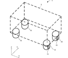
- FIG. 1 is a key map for explaining the composition of the leg structure of the audio equipment concerning one embodiment.
- FIG. 2 is a block diagram illustrating a configuration of an audio device according to an embodiment.
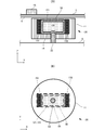
- FIG. 3A is a cross-sectional view of a leg structure of an audio device according to an embodiment.
- FIG. 3B is a bottom view of the leg structure of the audio device according to the embodiment.
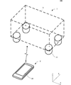
- FIG. 4 is a conceptual diagram for explaining a configuration of an acoustic system according to an embodiment.
- FIG. 5 is a block diagram illustrating a configuration of an audio device according to an embodiment.
- FIG. 6 is a block diagram illustrating a configuration of a mobile terminal according to an embodiment.
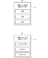
- FIG. 7A is a diagram for explaining an example of an input screen displayed for the user to input an instruction to control the viscosity of the viscous fluid from the mobile terminal.
- FIG. 7B is a diagram for describing a modification of the example illustrated in FIG.
- FIG. 8 is a cross-sectional view for explaining a configuration of a leg structure of an audio device according to another embodiment.
- FIG. 9A is a cross-sectional view of a leg structure of an audio device according to another embodiment.
- FIG. 9B is a bottom view of the leg structure of the audio device according to another embodiment.
- leg structure 10 of the audio equipment the leg structure 20 of the audio equipment, the leg structure 30 of the audio equipment, and the audio system 100 shown in the drawing are merely examples, and are not limited to this, and may be appropriately changed according to specifications. Can do.
- FIG. 1 is a conceptual diagram for explaining a configuration of a leg structure 10 of an amplifier 1 according to an embodiment.
- FIG. 2 is a block diagram showing a configuration of the amplifier 1 according to the embodiment.
- the amplifier 1 is an example of an “acoustic device” according to the present invention, and includes a housing 3 and a leg structure 10 as shown in FIG. Each leg structure 10 has a switch 16 on the side surface.
- the housing 3 is shown by a broken line and transmitted.
- the amplifier 1 includes a CPU 15, a RAM 52, a ROM 53, a DSP (Digital Signal Processor) 54, a switch 16, and a coil power supply circuit 56.
- a CPU central processing unit
- RAM 52 random access memory
- ROM 53 read-only memory
- DSP Digital Signal Processor
- the CPU 15 controls each unit of the amplifier 1.
- the CPU 15 performs the following various operations by reading out the program stored in the ROM 53, which is a storage medium, to the RAM 52.
- the CPU 15 is an example of the “control unit” according to the present invention.
- the ROM 53 is, for example, a flash memory, and stores various programs for the DSP 54, data for the DSP 54, a firmware program for controlling the basic operation of the amplifier 1, various control programs, and the like.
- the CPU 15 reads out programs stored in the ROM 53 and executes various control processes.
- the RAM 52 temporarily stores various data and functions as a working area.
- Various control programs may be recorded on other recording media (optical disk, magnetic disk, or the like) that can be read by the amplifier 1.
- the DSP 54 reads out the program or data for the DSP 54 stored in the ROM 53 under the control of the CPU 15 and performs various processes such as applying effects to the audio data read out from the ROM 53.
- the CPU 15 outputs an audio signal to which an effect is given by the DSP 54 to the communication unit 55.
- the switch 16 receives an instruction from the user and outputs the received instruction to the CPU 15.
- the switch 16 is an example of a “reception unit” according to the present invention.
- the CPU 15 controls the coil power supply circuit 56.
- the coil power supply circuit 56 receives a command from the CPU 15 and adds a predetermined current to the coil 151 and the coil 152 described later.
- the leg structure 10 supports the housing 3.
- the acoustic device is not limited to the amplifier 1, and any device related to various sounds such as a speaker, a BD player, or a CD player can be used as long as it includes the leg structure 10.
- the leg structures 10 are provided at four locations at the four corners of the bottom surface 4 of the housing 3, but it is only necessary to provide at least one location with respect to the housing 3.
- the leg structures 10 are each formed in a cylindrical shape, but the shape is not limited to a cylindrical shape, and other shapes such as a rectangular parallelepiped may be employed.
- one of the leg structures 10 provided at the four corners of the bottom surface 4 will be described.
- FIG. 3A is a cross-sectional view of the leg structure 10 of the amplifier 1 in the XZ plane shown in FIG.
- FIG. 3B is a bottom view of the leg structure 10 of the amplifier 1.
- a part of the leg structure 10 is shown to be transparent for convenience of explanation.
- the leg structure 10 is provided so as to contact the bottom surface 4 of the housing 3.
- the leg structure 10 includes a cover part 11, an enclosure part 12, a support part 13, a rubber 14, a CPU 15, a switch 16, a coil 151, and a coil 152.
- the cover part 11 includes a part of the enclosing part 12 and the support part 13 inside, and a switch 16 outside.
- the enclosure part 12 is formed in a shape having an internal space 121.
- the enclosing unit 12 encloses the viscous fluid 122 in the internal space 121.
- the viscous fluid 122 preferably has a variable viscosity and is a magnetorheological fluid.
- the magnetorheological fluid is a slurry in which metal fine particles are dispersed at a high concentration in a liquid such as oil.
- a strong magnetic field is applied to the magnetorheological fluid
- the metal fine particles in the magnetorheological fluid attract each other and the viscosity increases.
- the magnetic field applied to the magnetorheological fluid is weak, the viscosity becomes low because the metal fine particles are freely dispersed.
- the viscosity of the magnetorheological fluid can be changed by changing the strength of the applied magnetic field.
- the support part 13 includes a resistance part 131 and a cylindrical part 132.
- the support portion 13 is made of a nonmagnetic material.
- the support portion 13 is made of, for example, a plastic such as polyethylene (PE) or polyamide (PA) or a nonmagnetic metal.
- the resistance part 131 is located in the internal space 121 of the enclosing part 12.
- the resistance part 131 has a shape extending in parallel with the XY plane, and is in direct contact with the viscous fluid 122. For this reason, since the resistance portion 131 is in wide contact with the viscous fluid 122 in the XY plane, the movement in the Z-axis direction is easily affected by the viscosity of the viscous fluid 122.
- a part of the cylindrical part 132 is located in the internal space 121 of the enclosing part 12 and is in direct contact with the viscous fluid 122.
- the cylindrical portion 132 extends downward from the resistance portion 131 toward the outside of the cover portion 11.
- the support unit 13 is movable in the viscous fluid 122 according to the state of the viscous fluid 122.
- the side surface of the cylindrical portion 132 outside the cover portion 11 is covered with rubber 14.
- the upper surface of the rubber 14 is in contact with the bottom surface of the cover portion 11, and the bottom surface of the rubber 14 is in contact with the ground plane G.
- the bottom surface of the cylindrical portion 132 is in contact with the ground plane G on which the amplifier 1 is installed together with the bottom surface of the rubber 14, and the support portion 13 supports the housing 3 together with the rubber 14.
- the rubber 14 vibrates with the movement of the support portion 13.
- the rubber 14 is an example of an “elastic body” according to the present invention.
- the rubber 14 also has a damper function of absorbing vibration from the ground plane G or the housing 3.
- As the elastic body a material having elasticity such as brass, wood, or cork can be used besides rubber.
- the cover part 11 has two coils 151 and a coil 152 that are close to the enclosing part 12.
- the coil 151 and the coil 152 are arranged at positions where the encapsulating part 12 is sandwiched from both sides in plan view. Note that the wiring of the coil 151, the coil 152, and the switch 16 is omitted in FIGS. 3A and 3B.
- the switch 16 is provided on the outer peripheral surface of the leg structure 10.
- the switch 16 is not limited to the leg structure 10 and may be provided in the housing 3.
- the switch 16 receives an instruction from the user to control the viscosity of the viscous fluid 122 and outputs the received instruction to the CPU 15.
- the CPU 15 controls the viscosity of the viscous fluid 122 in response to an instruction from the switch 16.
- the coil power supply circuit 56 receives a command from the CPU 15 and adds a predetermined current to the coil 151 and the coil 152. For example, when the user turns on “high” of the switch 16, a higher current is applied to the coil 151 and the coil 152 than when “low” is turned on.
- the CPU 15 can change the magnetic field applied to the viscous fluid 122 according to the magnitude of the current applied to the coil 151 and the coil 152.
- the resistance part 131 located in the internal space 121 of the enclosure part 12 is restrained from moving in the Z-axis direction. Since the cylindrical portion 132 does not move significantly with respect to the enclosing portion 12, the deformation of the rubber 14 is reduced. Conversely, when the magnetic field applied to the viscous fluid 122 is weak, the viscosity of the viscous fluid 122 becomes low. Thereby, the resistance part 131 becomes easy to move to a Z-axis direction. Since the cylindrical portion 132 is easily moved largely with respect to the enclosing portion 12, the deformation of the rubber 14 is large.
- the degree of vibration absorption in the support portion 13 changes.
- the vibration characteristics of the leg structure 10 of the amplifier 1 change.
- the impedance in the wiring or the like changes.
- the impedance changes in the amplifier 1 the electrical characteristics are affected and the sound quality of the output signal changes.
- the viscosity of the viscous fluid 122 is high, the resonance frequency increases, and the high range is emphasized (the sound is clear).
- the viscosity of the viscous fluid 122 is low, the resonance frequency is lowered and the low range is emphasized (a heavy sound is produced). Therefore, by controlling the viscosity of the viscous fluid 122, it is possible to cause a change in the vibration characteristics received by the housing 3, so that the sound quality of the output signal can be adjusted according to the user's preference.
- FIG. 4 is a conceptual diagram for explaining the configuration of the acoustic system 100 according to an embodiment.
- the acoustic system 100 includes an amplifier 7 and a mobile terminal 2.
- the amplifier 7 and the portable terminal 2 are communicably connected by either wired or wireless.
- the amplifier 7 and the portable terminal 2 construct a wireless LAN via a wireless router to be connected or a wireless communication function of the own device.
- the wireless LAN connects the amplifier 7 and the mobile terminal 2 to each other.
- FIG. 5 is a block diagram showing a configuration of the amplifier 7 according to an embodiment.
- the amplifier 1 is an example of an “acoustic device” according to the present invention.
- the amplifier 7 has substantially the same configuration as that of the amplifier 1 except that it includes a communication unit 55 instead of the switch 16, and thus the description other than the communication unit 55 is omitted.
- the communication unit 55 is an interface that transmits and receives data to and from an external device such as the portable terminal 2 described later. For example, data can be transmitted / received to / from various external drive devices, audio devices, or personal computers via the communication unit 55.
- the amplifier 7 can transmit and receive data to and from a device connected to a communication network such as a LAN (Local Area Network) via the communication unit 55.
- a communication network such as a LAN (Local Area Network) via the communication unit 55.
- the network may be constructed by either wired or wireless.
- the portable terminal 2 is an example of an “information processing apparatus” according to the present invention.
- the portable terminal 2 is a laptop personal computer, a smartphone, a tablet terminal, or the like, and serves as a controller that controls the leg structure 10.
- FIG. 6 is a block diagram illustrating a configuration of the mobile terminal 2 according to an embodiment.
- the mobile terminal 2 includes a CPU 21, a RAM 22, a ROM 23, a display 24, and a communication unit 25.
- the CPU 21 includes a reception unit 17.
- the CPU 21 performs the following various operations by reading the program stored in the ROM 23 which is a storage medium into the RAM 22.
- the program includes an application for controlling the leg structure 10.
- the display 24 is a display attached to the mobile terminal 2.
- the display 24 includes a touch panel.
- the user can input instruction information for controlling the leg structure 10 by operating the display 24.
- the receiving unit 17 receives an instruction to control the viscosity of the viscous fluid 122 input from the display 24.
- the communication unit 25 inputs and outputs radio signals such as Wi-Fi (registered trademark) standard, Bluetooth (registered trademark) standard, and the like. With this communication unit 25, the mobile terminal 2 can communicate with the amplifier 7.
- the communication unit 25 transmits an instruction to control the viscosity of the viscous fluid 122 input from the display 24 to the CPU 15 of the amplifier 7.
- an instruction input method for controlling the viscosity of the viscous fluid 122 in the mobile terminal 2 will be described in detail.
- FIG. 7A is a diagram for explaining an example of an input screen displayed for the user to input an instruction to control the viscosity of the viscous fluid 122 from the mobile terminal 2.
- FIG. 7B is a diagram for describing a modification of the example illustrated in FIG.
- the user can use the mobile terminal 2 to select an area option suitable for music to be played back as will be described in detail below.
- options are displayed on the display 24 as shown in FIG.
- the choices are divided into three stages of sound, high, mid, and low. For example, when the user selects a high frequency, the viscosity of the viscous fluid 122 of the leg structure 10 is adjusted so that the high frequency range is emphasized.
- the high-level, middle-frequency, and low-frequency options are associated with predetermined current values flowing through the coil 151 and the coil 152, and are set in advance in the application of the mobile terminal 2.
- the predetermined current value associated with the option may be recorded in a memory (not shown) of the amplifier 7.
- the user may select a corresponding sound range of the input numerical value by inputting the numerical value.
- the portable terminal 2 instructs the viscous fluid 122 to have a viscosity suitable for the high range, that is, an instruction to flow a predetermined current value associated with the high range to the coil 151 and the coil 152.
- a viscosity suitable for the high range that is, an instruction to flow a predetermined current value associated with the high range to the coil 151 and the coil 152.
- Send. Specifically, when the user selects a high frequency, a relatively large current is passed through the coil 151 and the coil 152. Thereby, since the viscosity of the viscous fluid 122 becomes relatively high, the resonance frequency of the leg structure 10 becomes high. For this reason, the sound quality of the amplifier 7 changes to a state in which high-frequency sound is emphasized.
- the options displayed on the display 24 are not limited to three, and the options may be set in two or more stages divided into four or more.
- the user may select an option from the displayed option, or input by other characters or voice. You can also.
- the genre of music may be displayed on the display 24.
- the music genre and a predetermined current value flowing through the coil 151 and the coil 152 suitable for the music genre are linked in advance and set in advance in the application of the mobile terminal 2.
- the portable terminal 2 instructs the viscous fluid 122 to have a viscosity suitable for the lock (dance system), that is, a predetermined current associated with the lock (dance system).
- An instruction to send a value to the coil 151 and the coil 152 is transmitted.
- the CPU 15 causes a current having a predetermined current value to flow through the coil 151 and the coil 152 in accordance with the transmitted instruction.
- a relatively low current is passed through the coil 151 and the coil 152.
- the viscous fluid 122 becomes a low viscosity suitable for the lock (dance system) selected by the user.
- FIG. 8 is a cross-sectional view for explaining the configuration of the leg structure 20 of the amplifier 1 according to another embodiment.
- the leg structure 20 of the amplifier 1 has the same configuration as the leg structure 10 of the amplifier 1 except that the structure of the leg structure 10 of the amplifier 1 is arranged in the opposite direction in the Z-axis direction. For this reason, description of the same configuration as the leg structure 10 of the amplifier 1 is omitted.
- the leg structure 20 of the amplifier 1 includes a rubber 14 on the housing 3 side.
- the resistance part 131 is located below the cylindrical part 132 in the Z-axis direction.
- the cylindrical portion 132 extends upward from the resistance portion 131, and the upper surface thereof is in contact with the bottom surface 4 of the housing 3.
- the resistance part 131 can move in the viscous fluid 122 according to the state of the viscous fluid 122.
- the rubber 14 is elastically deformed with the movement of the support portion 13. For this reason, by changing the magnetic field applied to the viscous fluid 122, the degree of vibration absorption in the support portion 13 changes. Therefore, by controlling the viscosity of the viscous fluid 122, the vibration characteristics of the leg structure 20 of the amplifier 1 can be changed. Therefore, like the leg structure 10 of the amplifier 1, the leg structure 20 of the amplifier 1 can adjust the sound quality according to the user's preference.
- FIG. 9A is a cross-sectional view of a leg structure 30 of an audio device according to another embodiment.
- FIG. 9B is a bottom view of the leg structure 30 of the audio device according to another embodiment.
- the leg structure 30 of the amplifier 1 will be described.
- the leg structure 30 of the amplifier 1 is the leg structure 10 of the amplifier 1 except that the rubber 14 is the encapsulating part 32 and the shape of the support part 33 is different from the support part 13 and is indirectly in contact with the viscous fluid 122. It is the same composition as. For this reason, description of the same configuration as the leg structure 10 of the amplifier 1 is omitted.
- the leg structure 30 of the amplifier 1 has the rubber 14 as the enclosing portion 32. That is, the enclosure part 12 is formed in a closed bag shape, and the viscous fluid 122 is enclosed in the internal space 121.
- the encapsulating part 32 receives a force from the outside, the deformation state changes depending on the viscosity of the viscous fluid 122 encapsulated inside.
- the enclosure part 12 since the enclosure part 12 has a closed structure, it is easy to form and the enclosed viscous fluid 122 can be prevented from leaking outside.
- the support portion 33 is generally formed in a columnar shape, and the bottom surface, which is the lower end side of the support portion 33 in the Z-axis direction, is in contact with the ground plane G on which the amplifier 1 is installed.
- the upper end side of the support portion 33 in the Z-axis direction is in contact with the rubber 14, i.
- the support part 13 supports the housing
- the leg structure 30 of the amplifier 1 can adjust the sound quality according to the user's preference, like the leg structure 10 of the amplifier 1.
- the coil 151 and the coil 152 are used to change the viscosity of the viscous fluid 122, but other methods can be used as long as the viscosity of the viscous fluid 122 is changed.
- a material whose viscosity changes according to temperature or pressure can be used instead of the viscous fluid 122.
- the viscosity of the viscous fluid 122 is set to be low before use, and is adjusted by increasing the viscosity by passing a current through the coil 151 and the coil 152.
- the viscosity of the viscous fluid 122 is May be set higher.
- a resistance for generating heat is placed in the vicinity of the enclosing portion 32 enclosing the viscous fluid 122.
- the amount of heat given to the viscous fluid 122 can be adjusted. For this reason, when the viscous fluid 122 is a material whose viscosity decreases with temperature, the viscosity of the viscous fluid 122 can be reduced as compared with that before use.
- the viscosity of the viscous fluid 122 is adjusted to a uniform viscosity over all the leg structures (four), but may be adjusted to a different viscosity for each leg structure.
- the viscosity of the viscous fluid 122 inside the two leg structures may be set higher, and the viscosity of the viscous fluid 122 inside the other two leg structures may be set lower. it can.
- two types of vibration characteristics can be given to the leg structure, variations can be given to the vibration characteristics of the leg structure.
- the divided sound range and music genre are given, but other options can also be applied.
- the specification of the current value flowing through the coil 151 and the coil 152, the viscosity of the viscous fluid 122 divided into high and low degrees, the degree of vibration that is easy to vibrate or difficult to vibrate, or the characteristics of the sound output from the acoustic device It is possible to adapt even with such options.
- a correspondence relationship between the predetermined viscosity of the viscous fluid 122 in advance and the characteristics of the sound output from the acoustic device when the viscous fluid 122 has the predetermined viscosity is used. And stored in the memory of the audio equipment. Examples of sound characteristics include words that express the texture of sounds that humans feel, such as “spread” or “a sense of volume increases”. Further, the current value flowing through the coil 151 and the coil 152 in order to make the viscous fluid 122 have a predetermined viscosity is stored in the memory of the acoustic device.
- the user can output the sound of the sound quality corresponding to this by selecting the feature of the sound according to preference. For example, when the user selects a sound feature “spread”, the current value for making the viscous fluid 122 a predetermined viscosity so as to obtain the sound quality “spread” is obtained from the memory of the acoustic device. Read out. The CPU 15 passes a current having a predetermined current value read from the memory through the coil 151 and the coil 152. As a result, the viscosity of the viscous fluid 122 is adjusted, and the sound quality sound corresponding to the sound characteristic of “spreading” can be output from the acoustic device.
- the leg structure of the audio device can be applied to the audio device such as the amplifier 1, but the leg structure has a leg structure and is used by being installed, and has an external signal.
- Any device that outputs can be applied.
- electrical appliances such as a personal computer, a television, or a washing machine, or precision instruments such as various analyzers can be used.
Landscapes
- Circuit For Audible Band Transducer (AREA)
Abstract
ユーザの好みに応じて音質を調整することができる音響機器の脚構造(10,20,30)、及び音響システム(100)を提供する。 粘性流体(122)と、粘性流体(122)を内部空間(121)に封入する封入部(12)と、粘性流体(122)に直接または間接的に接し、筐体(3)を支持する支持部(13)と、支持部(13)の動きに伴って弾性変形するゴム(14)と、粘性流体(122)の粘性を制御するCPU(15)と、を備える。
Description
本発明の一実施形態は、音響機器を支持する脚構造及び、音響システムに関する。
オーディオ装置などの音響機器は概ね、筐体を支持する脚部を備える。微小な振動によっても音質に大きな影響がある音響機器においては、脚部の構造は音質に影響を及ぼす。特許文献1には、オーディオ機器の重量に応じて脚部の接地態様を2ウエイ方式で変化させるオーディオ機器の底脚構造が開示されている。
特許文献1のオーディオ機器の底脚構造においては、オーディオ機器の重量が、所定の重み以上か否かにより接地態様が変化するものである。このため、ユーザの好みに応じて音質を調整することはできない。
そこで、本発明の目的は、ユーザの好みに応じて音質を調整することができる音響機器の脚構造及び、音響システムを提供することにある。
本発明の一実施形態に係る音響機器の脚構造は、粘性流体と、前記粘性流体を内部空間に封入する封入部と、前記粘性流体に直接または間接的に接し、筐体を支持する支持部と、前記支持部の動きに伴って弾性変形する弾性体と、
前記粘性流体の粘性を制御する制御部と、を備えることを特徴とする。
前記粘性流体の粘性を制御する制御部と、を備えることを特徴とする。
本発明によれば、ユーザの好みに応じて音質を調整することができる。
以下、図面を参照して、本発明の一実施形態に係る音響機器の脚構造及び音響システムについて説明する。なお、図に示す音響機器の脚構造10、音響機器の脚構造20、音響機器の脚構造30及び音響システム100はあくまで一例であり、これに限られるものではなく仕様に応じて適宜変更することができる。
図1は、一実施形態に係るアンプ1の脚構造10の構成を説明するための概念図である。図2は、一実施形態に係るアンプ1の構成を示したブロック図である。アンプ1は本発明に係る「音響機器」の一例であり、図1に示すように、筐体3及び脚構造10を備える。脚構造10は、それぞれ側面部にスイッチ16を有する。図1において、筐体3は破線で、かつ透過させて示している。
図2に示すように、アンプ1は、CPU15、RAM52、ROM53、及びDSP(Digital Signal Processor)54、スイッチ16、及びコイル用電源回路56を備えている。
CPU15は、アンプ1の装置各部を制御する。CPU15は、記憶媒体であるROM53に記憶されているプログラムをRAM52に読み出すことで、以下の種々の動作を行なう。CPU15は、本発明に係る「制御部」の一例である。
ROM53は、例えばフラッシュメモリであり、DSP54用の各種プログラム及びDSP54用のデータ、並びにアンプ1の基本動作を司るファームウェアプログラム、及び各種制御プログラム等を格納している。CPU15はこのROM53に格納されたプログラム等を読み出して様々な制御処理を実行する。RAM52は、各種データを一時的に記憶してワーキングエリアとして機能する。なお、各種制御プログラムは、アンプ1での読取りが可能な他の記録媒体(光学ディスク、または磁気ディスク等)に記録されていてもよい。
DSP54は、CPU15の制御の下、ROM53に格納されたDSP54用のプログラムまたはデータを読み出し、ROM53から読み出したオーディオデータに対して効果付与等の各種処理を行う。CPU15は、DSP54によって効果付与等がなされたオーディオ信号を通信部55に出力する。
スイッチ16は、ユーザからの指示を受付け、CPU15に受付けた指示を出力する。スイッチ16は、本発明に係る「受付部」の一例である。CPU15は、スイッチ16からの指示を受けて、コイル用電源回路56を制御する。
コイル用電源回路56は、CPU15からの命令を受けて、後から説明するコイル151及びコイル152に所定の電流を付加する。
脚構造10は、筐体3を支えるものである。音響機器としては、アンプ1に限られず、脚構造10を備えるものであれば、スピーカ、BDプレーヤ、またはCDプレーヤ等の各種音響に関する機器が利用できる。なお、本実施形態において、脚構造10は筐体3の底面4の四隅の4か所に設けられているが、筐体3に対して一か所以上設けられていればよい。また、脚構造10はそれぞれ円筒状に形成されているが、形状は円筒状に限られず、直方体等、その他の形状も採用され得る。以下に、底面4の四隅の4か所に設けられた脚構造10のうちの一つについて説明する。
図3(A)は、アンプ1の脚構造10の図1に示すX-Z平面における断面図である。図3(B)は、アンプ1の脚構造10の底面図である。図3(B)においては、説明の便宜上、脚構造10の一部を透過させて示している。
図3(A)及び図3(B)に示すように、脚構造10は筐体3の底面4と接するように設けられている。脚構造10は、カバー部11、封入部12、支持部13、ゴム14、CPU15、スイッチ16、コイル151、及びコイル152を備える。カバー部11は、内部に封入部12、支持部13の一部を備え、外部にスイッチ16を備える。
封入部12は、内部空間121を有する形状に形成されている。封入部12は、粘性流体122を内部空間121に封入している。粘性流体122は、粘性が可変であり、磁気粘性流体であることが好ましい。磁気粘性流体は、金属微粒子を油等の液体中に高濃度で分散させたスラリーである。磁気粘性流体に強い磁場を印加すると、磁気粘性流体内の金属微粒子が相互に引き付けあうため粘度が高くなる。磁気粘性流体に印加する磁場が弱いと、金属微粒子が自由に分散しているため粘度が低くなる。このように、磁気粘性流体は、印加する磁場の強さを変えることにより、その粘性を変化させることができる。
支持部13は、抵抗部131及び円柱部132を備える。支持部13は、非磁性の材質からなる。支持部13は、例えば、ポリエチレン(PE)、ポリアミド(PA)等のプラスチックまたは非磁性の金属からなる。抵抗部131は、封入部12の内部空間121に位置する。抵抗部131は、X-Y平面に平行に広がった形状であり、粘性流体122に直接接している。このため、抵抗部131は、X-Y平面において粘性流体122と広く接しているため、Z軸方向の動きが粘性流体122の粘度の影響を受け易い。円柱部132は、その一部が封入部12の内部空間121に位置し、粘性流体122に直接接している。円柱部132は、抵抗部131からカバー部11の外部へ向けて下方に伸びる。支持部13は、粘性流体122内部で粘性流体122の状態に応じて移動可能である。
カバー部11の外部における円柱部132の側面は、ゴム14で周囲を覆われている。ゴム14の上面はカバー部11の底面と接し、ゴム14の底面は接地面Gに接する。円柱部132の底面は、ゴム14の底面と共にアンプ1を設置する接地面Gに接し、支持部13は、ゴム14と共に筐体3を支持する。
ゴム14は、支持部13の動きに伴って振動する。ゴム14は、本発明に係る「弾性体」の一例である。また、ゴム14は、接地面Gまたは筐体3からの振動を吸収するダンパーの機能も有する。なお、弾性体としては、ゴム以外にも、真鍮、木材、またはコルク等弾性を有する素材が使用できる。
カバー部11は、封入部12に近接する二つのコイル151及びコイル152を有する。コイル151及びコイル152は、封入部12を平面視して両側から挟みこむ位置に配置されている。なお、コイル151、コイル152及びスイッチ16の配線は、図3(A)及び図3(B)において省略されている。
スイッチ16は、脚構造10の外周面に設けられている。なお、スイッチ16は、脚構造10に限られず、筐体3に設けられていてもよい。スイッチ16は、ユーザからの粘性流体122の粘性を制御する指示を受付け、CPU15に受付けた指示を出力する。スイッチ16としては、例えば、「高」または「低」を切り替えるスイッチが用いられる。
CPU15は、スイッチ16からの指示を受けて、粘性流体122の粘性を制御する。コイル用電源回路56は、CPU15からの命令を受けて、コイル151及びコイル152に所定の電流を付加する。例えば、ユーザがスイッチ16の「高」をONにすると、「低」をONにした場合と比べてコイル151及びコイル152に高めの電流が付加される。
コイル151及びコイル152に電流が流れると、コイル151及びコイル152は磁場を発生する。これにより、封入部12の内部に封入された粘性流体122に磁場が印加される。CPU15は、コイル151及びコイル152に付加される電流の大きさにより、粘性流体122に印加される磁場を変化させることができる。
粘性流体122に印加される磁場が強いと、粘性流体122の粘性は高くなる。これにより、封入部12の内部空間121に位置する抵抗部131はZ軸方向への動きが抑制される。円柱部132は、封入部12に対して大きく移動しないため、ゴム14の変形は小さくなる。逆に、粘性流体122に印加される磁場が弱いと、粘性流体122の粘性は低くなる。これにより、抵抗部131は、Z軸方向へ移動し易くなる。円柱部132は、封入部12に対して大きく移動しやすいため、ゴム14の変形は大きい。このように、粘性流体122に印加される磁場を変化させることにより、支持部13における振動の吸収度合いが変化する。支持部13において振動の吸収度合いが変化すると、アンプ1の脚構造10の振動特性が変化する。アンプ1の脚構造10の振動特性が変化することにより、配線などにおけるインピーダンスに変化が生じる。アンプ1内部においてインピーダンスに変化が生じると、電気的特性に影響し、出力信号の音質に変化が生じる。例えば、粘性流体122の粘性が高いと、共振周波数が高くなり、高域が強調される(クリアな音になる)。逆に粘性流体122の粘性が低いと、共振周波数が低くなり、低域が強調される(重厚な音になる)。したがって、粘性流体122の粘性を制御することにより、筐体3が受ける振動特性に変化を生じさせることができるため、出力信号の音質をユーザの好みに応じて調整することができる。
図4は、一実施形態に係る音響システム100の構成を説明するための概念図である。音響システム100は、アンプ7及び携帯端末2を備える。アンプ7及び携帯端末2は、有線または無線のいずれかよって通信可能に接続されている。例えば、アンプ7及び携帯端末2は、接続される無線ルータ、または自装置が有する無線通信機能を介して、無線LANを構築する。無線LANは、アンプ7及び携帯端末2を相互に接続している。
図5は、一実施形態に係るアンプ7の構成を示したブロック図である。アンプ1は本発明に係る「音響機器」の一例である。アンプ7は、スイッチ16の代わりに通信部55を備える以外はアンプ1と概ね同様の構成であるため、通信部55以外の説明については省略する。
図5に示すように、通信部55は、後から説明する携帯端末2等の外部の機器とデータの送受信を行うインタフェースである。例えば、通信部55を介して外部の各種ドライブ装置、オーディオ機器、またはパーソナルコンピュータ等の機器との間でデータの送受信を行うことができる。また、アンプ7は、通信部55を介してLAN(Local Area Network)等の通信ネットワーク網に接続された機器との間でデータの送受信を行うことができる。なお、ネットワークは、有線または無線のいずれで構築されていてもよい。
携帯端末2は本発明に係る「情報処理装置」の一例である。携帯端末2は、ラップトップパソコン、スマートフォン、またはタブレット端末等であり、脚構造10を制御するコントローラとなる。
図6は、一実施形態に係る携帯端末2の構成を示したブロック図である。図6に示すように、携帯端末2は、CPU21、RAM22、ROM23、及びディスプレイ24、及び通信部25を備えている。CPU21は、受付部17を備えている。
CPU21は、記憶媒体であるROM23に記憶されているプログラムをRAM22に読み出すことで、以下の種々の動作を行なう。プログラムは、脚構造10の制御用のアプリケーションを含む。
ディスプレイ24は、携帯端末2に付属のディスプレイである。また、本実施形態においては、ディスプレイ24がタッチパネルを備える構成となっている。ユーザは、ディスプレイ24を操作することにより、脚構造10の制御のための指示の情報を入力することができる。受付部17は、ディスプレイ24で入力された粘性流体122の粘性を制御する指示を受付ける。
通信部25は、例えばWi-Fi(登録商標)規格、Bluetooth(登録商標)規格等の無線信号を入出力する。この通信部25により、携帯端末2は、アンプ7との通信が可能となる。通信部25は、ディスプレイ24で入力された粘性流体122の粘性を制御する指示をアンプ7のCPU15に送信する。以下、携帯端末2における粘性流体122の粘性を制御する指示の入力方法について詳細に説明する。
図7(A)は、ユーザが携帯端末2から粘性流体122の粘性を制御する指示を入力するために表示される入力画面の一例を説明するための図である。図7(B)は、図7(A)に示す一例の変形例を説明するための図である。
ユーザは、携帯端末2を使用して以下に詳細に説明するように再生する音楽に適した領域の選択肢を選択することができる。携帯端末2において脚構造10の制御のアプリケーションを起動することにより、図7(A)に示すように、選択肢がディスプレイ24に表示される。選択肢は、高域、中域、低域の三段階の音域に区分されている。例えば、ユーザが高域を選択すると、高域の音域が強調されるように脚構造10の粘性流体122の粘性が調整される。
高域、中域、低域の三段階の選択肢と、コイル151及びコイル152に流れる所定の電流値とが紐づけられ、携帯端末2のアプリケーションにおいて予め設定されている。なお、選択肢に紐づけられた所定の電流値は、アンプ7の不図示のメモリに記録されていてもよい。また、ユーザは数値を入力することにより、入力した数値の該当する音域が選択されるようにしてもよい。
ユーザが高域を選択すると、携帯端末2は粘性流体122が高域に適した粘性になるような指示、すなわち高域と紐づけられた所定の電流値をコイル151及びコイル152に流す指示を送信する。具体的には、ユーザが高域を選択すると、比較的大きな電流がコイル151及びコイル152に流される。これにより、粘性流体122の粘性が比較的高くなるため、脚構造10の共振周波数が高くなる。このためアンプ7の音質は、高域の音が強調される状態へ変化する。
なお、ディスプレイ24に表示される選択肢は三つに限られず、選択肢は二つまたは4つ以上に区分された複数段階で設定されていてもよい。また、入力方法は、ユーザがディスプレイ24に表示された入力指示の欄に触れた時に、選択肢を表示させ、その表示された選択肢から選択するようにしてもよく、その他文字や音声で入力することもできる。
また、図7(B)に示すように、ディスプレイ24には、音楽のジャンルが表示されてもよい。予め、音楽のジャンルと、音楽のジャンルに適したコイル151及びコイル152に流れる所定の電流値とが紐づけられ、携帯端末2のアプリケーションにおいて予め設定されている。例えば、ユーザがロック(ダンス系)を選択すると、携帯端末2は粘性流体122がロック(ダンス系)に適した粘性になるような指示、すなわちロック(ダンス系)と紐づけられた所定の電流値をコイル151及びコイル152に流す指示を送信する。
CPU15は送信された指示にしたがってコイル151及びコイル152に所定の電流値の電流を流す。ロック(ダンス系)においては一般的に低域が強調される状態が好ましいため、比較的低めの電流がコイル151及びコイル152に流される。これにより、粘性流体122はユーザが選択したロック(ダンス系)に適した低めの粘性になる。
また、クラッシックにおいては一般的に高域が強調される状態が好ましいため、比較的高めの電流値が設定されている。ポップスにおいては一般的に中域が強調される状態が好ましいため、ロック(ダンス系)及びクラッシックで設定されている電流値の中間くらいの電流値が設定されている。なお、選択肢はロック(ダンス系)、ポップス、またはクラッシック以外のものも設定されてもよい。また、一つの選択肢には、複数の音楽のジャンルを含めてもよい。
図8は、他の一実施形態に係るアンプ1の脚構造20の構成を説明するための断面図である。以下、アンプ1の脚構造20について説明する。アンプ1の脚構造20は、アンプ1の脚構造10の構造がZ軸方向に逆向きに配置されている点以外はアンプ1の脚構造10と同様の構成である。このため、アンプ1の脚構造10と同様の構成については説明を省略する。
図8に示すように、アンプ1の脚構造20は、筐体3側にゴム14を備える。抵抗部131は円柱部132よりZ軸方向下方に位置する。円柱部132は、抵抗部131から上方に伸び、その上面が筐体3の底面4に接している。
抵抗部131は、粘性流体122内部で粘性流体122の状態に応じて移動可能である。ゴム14は、支持部13の動きに伴って弾性変形する。このため、粘性流体122に印加される磁場を変化させることにより、支持部13における振動の吸収度合いが変化する。したがって、粘性流体122の粘性を制御することにより、アンプ1の脚構造20の振動特性に変化を生じさせることができる。このため、アンプ1の脚構造20は、アンプ1の脚構造10と同様に、音質をユーザの好みに応じて調整することができる。
図9(A)は、他の一実施形態に係る音響機器の脚構造30の断面図である。図9(B)は、他の一実施形態に係る音響機器の脚構造30の底面図である。以下、アンプ1の脚構造30について説明する。アンプ1の脚構造30は、ゴム14が封入部32であること、及び支持部33の形状が支持部13と異なり、粘性流体122に間接的に接している点以外はアンプ1の脚構造10と同様の構成である。このため、アンプ1の脚構造10と同様の構成については説明を省略する。
図9(A)及び図9(B)に示すように、アンプ1の脚構造30は、ゴム14が封入部32である。すなわち、封入部12は閉じられた袋状に形成されており、内部空間121に粘性流体122が封入されている。封入部32は、外部から力を受けると、内部に封入された粘性流体122の粘性によって、変形具合が変化する。この実施形態において、封入部12は閉じられた構造であるため形成が容易であり、かつ封入されている粘性流体122が外部へ漏れ出すことが防止できる。
支持部33は、概ね円柱状に構成されており、支持部33のZ軸方向の下端側である底面は、アンプ1を設置する接地面Gに接している。支持部33は、Z軸方向の上端側がゴム14すなわち封入部32の底面と接している。このため、支持部13は、封入部32(ゴム14)と共に筐体3を支持する。
封入部32の内部に封入された粘性流体122の粘性を変化させることにより、支持部33における振動の吸収度合いが変化する。したがって、粘性流体122の粘性を制御することにより、アンプ1の脚構造30の振動特性に変化を生じさせることができる。このため、アンプ1の脚構造30は、アンプ1の脚構造10と同様に、音質をユーザの好みに応じて調整することができる。
なお、本実施形態において、粘性流体122の粘性を変化させるためにコイル151及びコイル152を用いたが、粘性流体122の粘性を変化させる方法であればその他の手法を用いることができる。例えば、温度や圧力によって粘性が変化する素材を粘性流体122の代わりに用いることができる。
なお、本実施形態において、粘性流体122の粘性は使用前に低く設定され、コイル151及びコイル152に電流を流して、粘性を上げることにより調整しているが、粘性流体122の粘性は使用前に高く設定されていてもよい。例えば、粘性流体122の封入された封入部32の付近に熱が発生する抵抗を置く場合が挙げられる。抵抗で発生させる熱の発生量を調整することにより、粘性流体122に与える熱量を調整することができる。このため、粘性流体122が温度によって粘性が低くなる素材である場合、粘性流体122の粘性を使用前に比べて低くすることができる。
なお、本実施形態において、粘性流体122の粘性は、脚構造(4本)全てに亘って均一な粘性に調整されているが、脚構造毎に異なる粘性に調整されてもよい。例えば、脚構造を四本備える音響機器において、二本の脚構造内部の粘性流体122の粘性を高めに、またその他の二本の脚構造内部の粘性流体122の粘性を低めに設定することができる。これにより、脚構造に二種類の振動特性を持たせることができるため、脚構造の振動特性にバリエーションを持たせることができる。
なお、本実施形態において、脚構造10の振動特性を調整するための選択肢の例として、区分された音域、及び音楽のジャンルを挙げたが、他の選択肢でも適応できる。例えば、コイル151及びコイル152に流す電流値の指定、粘性流体122の粘度を高低の度合いで区分したもの、振動し易いもしくは振動し難いという振動の程度、または音響機器から出力される音の特徴等の選択肢でも適応できる。
音響機器から出力される音の特徴による選択肢としては、予め粘性流体122の所定の粘度と、粘性流体122が該所定の粘度であるときの音響機器から出力される音の特徴との対応関係を、音響機器のメモリに記憶させておく。音の特徴としては、例えば、「広がりがある」、または「量感がアップする」などヒトが感じられる音の質感を言葉で表現したもの等が挙げられる。また、粘性流体122を所定の粘度にするためにコイル151及びコイル152に流す電流値について音響機器のメモリに記憶させておく。ユーザは、好みに応じて音の特徴を選択することにより、これに対応する音質の音を音響機器から出力することができる。例えば、ユーザが「広がりがある」という音の特徴を選択した場合、「広がりがある」という音の音質になるように粘性流体122を所定の粘度にするための電流値が音響機器のメモリから読み出される。CPU15は、メモリから読み出された所定の電流値の電流をコイル151及びコイル152に流す。これにより、粘性流体122の粘度が調整され、「広がりがある」という音の特徴に対応する音質の音を音響機器から出力することができる。
なお、本実施形態において、音響機器の脚構造は、アンプ1等の音響機器に適用できるものであるが、脚構造を有し、設置することにより使用される機器であって、外部に何らかの信号を出力する機器であれば、適用可能である。例えば、パーソナルコンピュータ、テレビ、もしくは洗濯機などの電化製品、または各種分析装置などの精密機器などが挙げられる。これらの機器に音響機器の脚構造を適用することにより、機器の振動特性を変化させることが可能となるため、使用状況に応じて出力を変化させることができる。
1,7…アンプ(音響機器)
2…携帯端末(情報処理装置)
3…筐体
10,20,30…音響機器の脚構造
12,32…封入部
13,33…支持部
14…ゴム(弾性体)
15…制御部
16…スイッチ(受付部)
17…受付部
100…音響システム
121…内部空間
122…粘性流体
2…携帯端末(情報処理装置)
3…筐体
10,20,30…音響機器の脚構造
12,32…封入部
13,33…支持部
14…ゴム(弾性体)
15…制御部
16…スイッチ(受付部)
17…受付部
100…音響システム
121…内部空間
122…粘性流体
Claims (7)
- 粘性流体と、
前記粘性流体を内部空間に封入する封入部と、
前記粘性流体に直接または間接的に接し、筐体を支持する支持部と、
前記支持部の動きに伴って弾性変形する弾性体と、
前記粘性流体の粘性を制御する制御部と、
を備える音響機器の脚構造。 - 前記粘性流体は磁気粘性流体であり、
前記制御部は、前記粘性流体に印加する磁場の強さを変えることで前記粘性流体の粘性を制御する請求項1に記載の音響機器の脚構造。 - 前記弾性体は前記封入部である請求項1または2に記載の音響機器の脚構造。
- ユーザからの前記粘性流体の粘性を制御する指示を受付け、前記制御部に受付けた前記指示を出力する受付部をさらに備える請求項1から3のいずれかに記載の音響機器の脚構造。
- 前記受付部は、ユーザからの前記粘性流体の粘性を制御する指示を予め区分された複数段階で受付ける請求項4に記載の音響機器の脚構造。
- 前記複数段階は、再生する音のジャンルに応じて区分されている請求項5に記載の音響機器の脚構造。
- 請求項1から6のいずれかに記載の音響機器の脚構造と、
前記粘性流体の粘性を制御する指示を前記制御部へ送信する情報処理装置と、
を備える音響システム。
Priority Applications (1)
| Application Number | Priority Date | Filing Date | Title |
|---|---|---|---|
| PCT/JP2017/012030 WO2018173259A1 (ja) | 2017-03-24 | 2017-03-24 | 音響機器の脚構造及び、音響システム |
Applications Claiming Priority (1)
| Application Number | Priority Date | Filing Date | Title |
|---|---|---|---|
| PCT/JP2017/012030 WO2018173259A1 (ja) | 2017-03-24 | 2017-03-24 | 音響機器の脚構造及び、音響システム |
Publications (1)
| Publication Number | Publication Date |
|---|---|
| WO2018173259A1 true WO2018173259A1 (ja) | 2018-09-27 |
Family
ID=63586499
Family Applications (1)
| Application Number | Title | Priority Date | Filing Date |
|---|---|---|---|
| PCT/JP2017/012030 Ceased WO2018173259A1 (ja) | 2017-03-24 | 2017-03-24 | 音響機器の脚構造及び、音響システム |
Country Status (1)
| Country | Link |
|---|---|
| WO (1) | WO2018173259A1 (ja) |
Citations (3)
| Publication number | Priority date | Publication date | Assignee | Title |
|---|---|---|---|---|
| JP2000274478A (ja) * | 1999-03-24 | 2000-10-03 | Makoto Morishita | 精密機器用制振装置 |
| JP2012129575A (ja) * | 2010-12-10 | 2012-07-05 | Tokkyokiki Corp | オーディオ用インシュレータ及びオーディオ・システム |
| JP2012230729A (ja) * | 2011-04-25 | 2012-11-22 | Tokkyokiki Corp | オーディオ用インシュレータ及びその評価方法 |
-
2017
- 2017-03-24 WO PCT/JP2017/012030 patent/WO2018173259A1/ja not_active Ceased
Patent Citations (3)
| Publication number | Priority date | Publication date | Assignee | Title |
|---|---|---|---|---|
| JP2000274478A (ja) * | 1999-03-24 | 2000-10-03 | Makoto Morishita | 精密機器用制振装置 |
| JP2012129575A (ja) * | 2010-12-10 | 2012-07-05 | Tokkyokiki Corp | オーディオ用インシュレータ及びオーディオ・システム |
| JP2012230729A (ja) * | 2011-04-25 | 2012-11-22 | Tokkyokiki Corp | オーディオ用インシュレータ及びその評価方法 |
Similar Documents
| Publication | Publication Date | Title |
|---|---|---|
| US10063976B2 (en) | Headphones for stereo tactile vibration, and related systems and methods | |
| US10667051B2 (en) | Methods and apparatus for limiting the excursion of a transducer | |
| JP5111746B2 (ja) | 携帯装置のためのオーディオ・システム | |
| EP3054702B1 (en) | Speakers and headphones related to vibrations in an audio system, and methods for operating same | |
| US9609421B2 (en) | Apparatus and methods related to a tactile vibrator for a speaker system | |
| KR20160078226A (ko) | 고대역폭 햅틱 효과의 오디오 향상된 시뮬레이션 | |
| WO2012050771A1 (en) | Electronic devices with improved audio | |
| US9752568B2 (en) | Apparatus and method for providing a user interface to an information processing system | |
| JPWO2017179538A1 (ja) | スピーカ駆動装置、スピーカ装置およびプログラム | |
| US20190384564A1 (en) | Playback system, vibrator, and playback system control method | |
| JP2020107318A (ja) | ハプティック効果信号処理 | |
| WO2018173259A1 (ja) | 音響機器の脚構造及び、音響システム | |
| US10048927B2 (en) | Audio display playback control | |
| US8494206B2 (en) | Electronic device and method thereof | |
| US7525794B2 (en) | Expandable acoustic chamber for computer systems | |
| KR20160020307A (ko) | 체감진동형 복합 음향리시버 | |
| US11323811B2 (en) | Acoustic device and acoustic reproduction method for producing high quality bass sound | |
| CN207397706U (zh) | 一种留声机 | |
| KR20220024632A (ko) | 햅틱 변환기들에 대한 주파수-도메인 햅틱 파형 보상 | |
| JP7348368B1 (ja) | 情報処理システム、情報処理装置、プログラム、および、制御方法 | |
| Rodriguez Mora et al. | Computational Analysis of an Electrodynamic Speaker and Implementation in 3D Printing | |
| KR20090041585A (ko) | 오디오 출력을 최적화하기 위한 장치 및 방법 | |
| CN105681956B (zh) | 人声高保真音箱 | |
| JP2010114612A (ja) | 小型スピーカを備える表示器、及び小型スピーカ構造 | |
| HK1140890A (en) | Audio system for portable device |
Legal Events
| Date | Code | Title | Description |
|---|---|---|---|
| 121 | Ep: the epo has been informed by wipo that ep was designated in this application |
Ref document number: 17901630 Country of ref document: EP Kind code of ref document: A1 |
|
| NENP | Non-entry into the national phase |
Ref country code: DE |
|
| 122 | Ep: pct application non-entry in european phase |
Ref document number: 17901630 Country of ref document: EP Kind code of ref document: A1 |
|
| NENP | Non-entry into the national phase |
Ref country code: JP |