WO2018173214A1 - Separation column housing holder, separation column replacement device, and replacement method - Google Patents
Separation column housing holder, separation column replacement device, and replacement method Download PDFInfo
- Publication number
- WO2018173214A1 WO2018173214A1 PCT/JP2017/011822 JP2017011822W WO2018173214A1 WO 2018173214 A1 WO2018173214 A1 WO 2018173214A1 JP 2017011822 W JP2017011822 W JP 2017011822W WO 2018173214 A1 WO2018173214 A1 WO 2018173214A1
- Authority
- WO
- WIPO (PCT)
- Prior art keywords
- separation column
- storage holder
- column storage
- separation
- longitudinal direction
- Prior art date
Links
Images


Definitions
- the cross-sectional schematic diagram which shows the structural example of a separation column exchange apparatus.
- the time sequence figure explaining the example of operation of a separation column exchange device.
- the schematic diagram which shows the structural example of a separation column storage holder.
- the schematic diagram which shows the structural example of a separation column storage holder.
- Example 1 describes a separation column storage holder and a separation column exchange apparatus that have a connecting portion that can move in the axial direction of the separation column and can be fixed in the separation column feeding direction.
- the longitudinal direction of the separation column is the Y-axis direction of the XYZ orthogonal coordinate system
- the separation column feed direction for separation column replacement is the Z-axis direction.
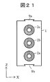
- FIG. 21 is a schematic cross-sectional view showing a configuration example of the separation column storage holder 1 of the present embodiment. Since the basic configuration is substantially the same as in FIG. 9, the differences will be described. In this configuration, a plurality of separation columns 2 a, 2 b, 2 c are accommodated in one separation column storage holder 1 between two side surfaces provided with the hook portions 9 a, 9 b of the connection portion.
- the separation column exchange device can have the same configuration as in the first embodiment.
- Example 19 In the nineteenth embodiment, a separation column storage holder and a separation column exchange device having a connecting portion that can move in the X-axis direction and can be fixed in the Z-axis direction will be described.
Abstract
Provided is a separation column housing holder 1 holding therein a separation column 2 filled with filler, and having connection parts 8 for connecting this separation column housing holder 1 to another separation column housing holder 1, said connection parts being provided on two side surfaces of the separation column housing holder 1 that are parallel to the separation column in the longitudinal direction.
Description
本発明は、高スループット分析を実現できる分離カラム収納ホルダ、分離カラム交換装置及び交換方法に関する。
The present invention relates to a separation column storage holder, a separation column exchange device, and a exchange method that can realize high-throughput analysis.
液体クロマトグラフ(LC)や固相抽出(SPE)などでは、充填剤を詰めた分離カラムにより試料を分離することで、夾雑物除去や高精度かつ高S/N分析を実現できる。分離カラムは測定対象試料によって交換したり、寿命が来た場合などに交換する必要がある。これらの分離カラムの交換作業は、スパナなどの工具を用いて押しネジを回して配管及びフェラルを着脱するのが一般的であり、作業者の熟練度によっては締め付け不良でシール部からリークする場合がある。リークが生じると、試料分離の分析性能の指標となる保持時間などの再現性が低下する。特に高速LCなど高耐圧が必要な場合には、再現性の高いシール性能は非常に重要となる。
In liquid chromatograph (LC), solid phase extraction (SPE), etc., separation of contaminants and high precision and high S / N analysis can be realized by separating the sample with a separation column packed with a packing material. It is necessary to replace the separation column depending on the sample to be measured or when the lifetime has come to an end. When replacing these separation columns, it is common to use a tool such as a spanner to turn the push screw to attach and detach the piping and ferrule. Depending on the skill level of the operator, the seal may leak due to poor tightening. There is. When the leak occurs, the reproducibility such as the retention time, which is an index of the analysis performance of the sample separation, decreases. In particular, when high breakdown voltage such as high-speed LC is required, highly reproducible sealing performance is very important.
この課題への対策として特許文献1,2などがある。これらの文献は自動で分離カラムを交換する技術に関するものであり、工具不要で分離カラムと配管(フィッティング)を接続することができる。
There are Patent Documents 1 and 2 as measures against this problem. These documents relate to a technique for automatically exchanging a separation column, and a separation column and piping (fitting) can be connected without a tool.
特許文献1,2に記載された装置構成では、予め装置にセットした複数の分離カラムを分析ライン位置(試料溶液を流すライン)へ自動で移動し、自動で分離カラムとフィッティングを接続することが出来る。しかし、装置にセットした分離カラムの予備が無くなった時点で、装置を停止して新品の分離カラムをセットする必要がある。つまり、予備の分離カラムをセットする際に分析が停止するため、分析のスループットが低下する。
In the apparatus configuration described in Patent Documents 1 and 2, it is possible to automatically move a plurality of separation columns set in the apparatus in advance to the analysis line position (line through which the sample solution flows) and automatically connect the separation column and the fitting. I can do it. However, when there is no longer any spare separation column set in the apparatus, it is necessary to stop the apparatus and set a new separation column. That is, the analysis is stopped when the spare separation column is set, so that the analysis throughput decreases.
本発明の一態様としての分離カラム収納ホルダは、充填剤を詰めた分離カラムを保持する分離カラム収納ホルダであって、分離カラムの長手方向に平行な2つの側面に分離カラム収納ホルダ同士を接続するための接続部を有する。接続部は、一例として分離カラムの長手方向に、又は長手方向と直交する方向に分離カラム収納ホルダ同士をスライドさせて接続する構造を有する。
A separation column storage holder according to an aspect of the present invention is a separation column storage holder for holding a separation column packed with a filler, and the separation column storage holders are connected to two side surfaces parallel to the longitudinal direction of the separation column. Having a connecting portion. As an example, the connecting portion has a structure in which the separation column storage holders are slid and connected in the longitudinal direction of the separation column or in a direction perpendicular to the longitudinal direction.
本発明の他の態様としての分離カラム交換装置は、収納した分離カラムの長手方向に平行な2つの側面に設けられた接続部で互いに着脱自在に接続された複数の分離カラム収納ホルダを前記長手方向に対して直交する方向に搬送するZ軸ステージと、上流側配管が固定された第1フィッティング及び下流側配管が固定された第2フィッティングをそれぞれ保持し、Z軸ステージによって分析ライン位置に搬送された分離カラムに対して接近する方向及び離間する方向に駆動されるY軸ステージと、を有する。
The separation column exchange device according to another aspect of the present invention includes a plurality of separation column storage holders that are detachably connected to each other at connection portions provided on two side surfaces parallel to the longitudinal direction of the stored separation column. Holds the Z-axis stage that transports in a direction perpendicular to the direction, the first fitting with the upstream piping fixed, and the second fitting with the downstream piping fixed, and transports them to the analysis line position by the Z-axis stage. And a Y-axis stage driven in a direction approaching and separating from the separation column.
また、本発明の他の態様である分離カラム交換方法は、分析ライン位置にセットされて使用中の分離カラムの使用回数が使用寿命回数未満の所定回数を経過した時点でアラートを出す工程と、アラートが出されてから使用回数が使用寿命回数に達するまでの間に、使用中の分離カラムを収納した第1の分離カラム収納ホルダの長手方向に平行な側面に設けられた接続部に対して予備の分離カラムを収納した第2の分離カラム収納ホルダの長手方向に平行な側面に設けられた接続部をスライドさせて両者を接続する工程と、使用中の分離カラムの使用回数が使用寿命回数に達した時点で、使用中の分離カラムから、上流側配管を接続するための第1フィッティング及び下流側配管を接続するための第2フィッティングを開放する工程と、第1の分離カラム収納ホルダと第2の分離カラム収納ホルダを接続したまま移動させ、予備の分離カラムを分析ライン位置にセットする工程と、分析ライン位置にセットされた予備の分離カラムに第1フィッティング及び第2フィッティングを接続する工程と、を有する。
In addition, the separation column exchange method according to another aspect of the present invention includes a step of issuing an alert when a predetermined number of times less than the number of use lifetimes has elapsed after the number of use of the separation column set in the analysis line position and being used is; For the connection portion provided on the side surface parallel to the longitudinal direction of the first separation column storage holder that stores the separation column in use, from the time when the alert is issued until the number of times of use reaches the number of use lifetimes. The step of sliding the connecting portion provided on the side surface parallel to the longitudinal direction of the second separation column storage holder storing the spare separation column to connect them, and the number of times the separation column is in use is the number of times of use The first fitting for connecting the upstream piping and the second fitting for connecting the downstream piping are released from the separation column in use, The separation column storage holder and the second separation column storage holder are moved while being connected, and the spare separation column is set at the analysis line position, and the first fitting and the first fitting are performed on the spare separation column set at the analysis line position. Connecting two fittings.
本発明により、分析中に予備の分離カラムをセットできるため、セット時や交換時の装置停止が不要となる。よって、分析の高スループット化が実現できる。
According to the present invention, a preliminary separation column can be set during analysis, so that it is not necessary to stop the apparatus at the time of setting or replacement. Therefore, high throughput of analysis can be realized.
上記した以外の、課題、構成及び効果は、以下の実施形態の説明により明らかにされる。
Issues, configurations, and effects other than those described above will be clarified by the following description of the embodiments.
以下、図面を参照して本発明の実施の形態を説明する。
[実施例1]
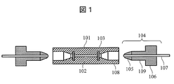
図1及び図2は従来の一般的な分離カラムを示す断面模式図であり、図1は開放状態を示し、図2は接続状態を示している。図1に示すように、分離カラム101は充填剤102を詰めた円筒体で、充填剤の両側にフィルターの役目をするフリット103、配管107を接続するためのメネジ部108などを有する。配管107の接続は、フィッティング104(フェラル105と押しネジ106)を用いて行う。図2に示すように、押しネジ106のオネジ部109を、分離カラム101のメネジ部108に対し矢印110のように回転させてフェラル105を押し進め、フェラル105と分離カラム101のテーパ部によりシールが可能となる。このとき、フェラル105の先端内径と配管107の外径が密着し、シールされる。これにより、条件によっては100MPa程度の耐圧が得られ、高流量送液による高速LC分離が可能となる。 Embodiments of the present invention will be described below with reference to the drawings.
[Example 1]
1 and 2 are cross-sectional schematic views showing a conventional general separation column. FIG. 1 shows an open state, and FIG. 2 shows a connected state. As shown in FIG. 1, theseparation column 101 is a cylindrical body packed with a packing material 102, and has a frit 103 that serves as a filter on both sides of the packing material, a female screw portion 108 for connecting a pipe 107, and the like. The pipe 107 is connected using a fitting 104 (ferrule 105 and set screw 106). As shown in FIG. 2, the ferrule 105 is pushed forward by rotating the male screw portion 109 of the push screw 106 with respect to the female screw portion 108 of the separation column 101 as indicated by an arrow 110, and the seal is sealed by the ferrule 105 and the tapered portion of the separation column 101. It becomes possible. At this time, the inner diameter of the tip of the ferrule 105 and the outer diameter of the pipe 107 are brought into close contact with each other and sealed. Thereby, a pressure resistance of about 100 MPa is obtained depending on conditions, and high-speed LC separation by high flow rate liquid feeding is possible.
[実施例1]
図1及び図2は従来の一般的な分離カラムを示す断面模式図であり、図1は開放状態を示し、図2は接続状態を示している。図1に示すように、分離カラム101は充填剤102を詰めた円筒体で、充填剤の両側にフィルターの役目をするフリット103、配管107を接続するためのメネジ部108などを有する。配管107の接続は、フィッティング104(フェラル105と押しネジ106)を用いて行う。図2に示すように、押しネジ106のオネジ部109を、分離カラム101のメネジ部108に対し矢印110のように回転させてフェラル105を押し進め、フェラル105と分離カラム101のテーパ部によりシールが可能となる。このとき、フェラル105の先端内径と配管107の外径が密着し、シールされる。これにより、条件によっては100MPa程度の耐圧が得られ、高流量送液による高速LC分離が可能となる。 Embodiments of the present invention will be described below with reference to the drawings.
[Example 1]
1 and 2 are cross-sectional schematic views showing a conventional general separation column. FIG. 1 shows an open state, and FIG. 2 shows a connected state. As shown in FIG. 1, the
実施例1では、分離カラムの軸方向に移動可能で分離カラム送り方向に固定可能な接続部を有する分離カラム収納ホルダ及び分離カラム交換装置について説明する。以下では、分離カラムの長手方向がXYZ直交座標系のY軸方向、分離カラム交換のための分離カラム送り方向がZ軸方向であるとして説明する。
Example 1 describes a separation column storage holder and a separation column exchange apparatus that have a connecting portion that can move in the axial direction of the separation column and can be fixed in the separation column feeding direction. In the following description, it is assumed that the longitudinal direction of the separation column is the Y-axis direction of the XYZ orthogonal coordinate system, and the separation column feed direction for separation column replacement is the Z-axis direction.
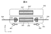
図3~6は、分離カラム交換装置を構成する分離カラム収納ホルダ移動機構及びフィッティング着脱装置の動作シーケンスの一例を示す断面模式図である。分析ライン位置301にセットされた分離カラム202は、内部の充填剤203により上流側配管204から流れてきた試料溶液を分離する。つまり、分析ライン位置301とは、分離カラム202に試料を流し分析を行う位置のことである。上流側配管204は第1フィッティング205により分離カラム202に接続されており、同様に下流側配管206は第2フィッティング207により分離カラム202に接続されている。上流側配管204はLCポンプ(図示せず)などと接続し、下流側配管206は検出器(図示せず)などと接続している。
FIGS. 3 to 6 are schematic cross-sectional views showing an example of the operation sequence of the separation column storage holder moving mechanism and the fitting attachment / detachment device constituting the separation column exchange device. The separation column 202 set at the analysis line position 301 separates the sample solution flowing from the upstream side pipe 204 by the internal packing material 203. That is, the analysis line position 301 is a position where a sample is passed through the separation column 202 and analysis is performed. The upstream pipe 204 is connected to the separation column 202 by a first fitting 205, and similarly, the downstream pipe 206 is connected to the separation column 202 by a second fitting 207. The upstream pipe 204 is connected to an LC pump (not shown) or the like, and the downstream pipe 206 is connected to a detector (not shown) or the like.
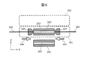
まず、図3のように分析ライン位置301で分析中に予備の分離カラム202’を予備カラムセット位置302にセットする。使用中の分離カラム202が寿命に達した場合や、次の分析で異なる種類のカラムを使用する場合、図4のようにフィッティング205,207を矢印401,402のようにカラムから離脱する方向に移動し、分離カラム202との接続を解除する。その後、図5の矢印403のように、分離カラム202をZ方向に移動する。その際、予備の分離カラム202’も道連れに移動できることがポイントとなる。道連れに移動した予備の分離カラム202’は分析ライン位置301にセットされ、その後、図6に矢印404,405で示すようにフィッティング205,207をY方向に移動し分離カラム202’と接続することで、分離カラム202’の充填剤203’を利用した分析が可能となる。
First, as shown in FIG. 3, the spare separation column 202 ′ is set at the spare column set position 302 during the analysis at the analysis line position 301. When the separation column 202 in use reaches the end of its life or when a different type of column is used in the next analysis, the fittings 205 and 207 are moved away from the column as indicated by arrows 401 and 402 as shown in FIG. It moves and the connection with the separation column 202 is released. Thereafter, the separation column 202 is moved in the Z direction as indicated by an arrow 403 in FIG. At that time, the point is that the spare separation column 202 ′ can also be moved along. The spare separation column 202 ′ that has moved along with it is set at the analysis line position 301, and then the fittings 205 and 207 are moved in the Y direction and connected to the separation column 202 ′ as indicated by arrows 404 and 405 in FIG. Thus, analysis using the packing material 203 ′ of the separation column 202 ′ becomes possible.
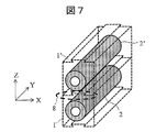
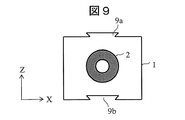
図7~9は、分離カラム収納ホルダの一例の構成例を示す概略図である。図7は分離カラム収納ホルダ1の全体を示す模式図、図8は分離カラム収納ホルダ1同士を接続する接続部8の例を示す詳細模式図、図9は分離カラム収納ホルダ1を上流方向(又は下流方向)からみた側面模式図である。
7 to 9 are schematic views showing an example of the configuration of an example of the separation column storage holder. 7 is a schematic diagram showing the entire separation column storage holder 1, FIG. 8 is a detailed schematic diagram showing an example of a connection portion 8 for connecting the separation column storage holders 1 to each other, and FIG. 9 shows the separation column storage holder 1 in the upstream direction ( It is a schematic side view as viewed from the downstream direction.
分離カラム2を収納可能な本実施例の分離カラム収納ホルダ1はZ軸方向の2つの側面、すなわち長手方向に平行かつ互いに平行な2つの側面に分離カラム収納ホルダ同士を接続するための接続部8を有し、接続部8により予備の分離カラム2’を収納した予備の分離カラム収納ホルダ1’と着脱自在にZ軸方向に接続できる。図8に示すように、接続部8にはY軸方向にスライド可能、かつ、Z軸方向の動きを固定可能なアリ溝形状の引掛り部9が設けられている。より詳細には、接続部8は、図9に示すように分離カラム収納ホルダ1の上側と下側の2つの側面に、各々、凸形状と凹形状の引掛り部9a,9bを有する。引掛り部9aは予備の分離カラム収納ホルダ1’の引掛り部9bと接続できる。この構造により、分離カラム2で分析中に、上流方向(又は下流方向)から予備の分離カラム2’(分離カラム収納ホルダ1’)をY軸方向すなわち分離カラムの長手方向にスライドさせて接続することが可能となる。
The separation column storage holder 1 of the present embodiment capable of storing the separation column 2 is a connecting portion for connecting the separation column storage holders to two side surfaces in the Z-axis direction, that is, two side surfaces parallel to the longitudinal direction and parallel to each other. 8 and can be detachably connected to the spare separation column storage holder 1 ′ in which the spare separation column 2 ′ is housed by the connecting portion 8 in the Z-axis direction. As shown in FIG. 8, the connecting portion 8 is provided with a dovetail-shaped hook portion 9 that can slide in the Y-axis direction and can be fixed in the Z-axis direction. More specifically, as shown in FIG. 9, the connection portion 8 has convex and concave hook portions 9a and 9b on the two upper and lower side surfaces of the separation column storage holder 1, respectively. The hook 9a can be connected to the hook 9b of the spare separation column storage holder 1 '. With this structure, during the analysis in the separation column 2, the spare separation column 2 ′ (separation column storage holder 1 ′) is slid in the Y-axis direction, that is, the longitudinal direction of the separation column and connected from the upstream direction (or downstream direction). It becomes possible.
図10は、図7~9で説明した分離カラム収納ホルダ1を搭載した分析システム及び分離カラム交換装置の構成例を示す概略図である。
FIG. 10 is a schematic diagram showing a configuration example of an analysis system and a separation column exchange device on which the separation column storage holder 1 described in FIGS. 7 to 9 is mounted.
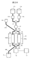
分析システムは、移動相11a又は移動相11b又は両者をミキサー13で混合したものをポンプ12a,12bにより上流側配管4に送液する。試料はオートサンプラー14に注入される。移動相11a,11bには、有機溶媒や水などを使用するのが一般的である。試料は、上流側配管4、第1フィッティング5、分離カラム2、第2フィッティング7、下流側配管6の順番に矢印15の方向に流れ、充填剤3で分離された試料は検出器16に到達して検出され、データ処理部17で分析される。検出器16には、質量分析計、紫外可視光検出器、フォトダイオードアレイ検出器、蛍光検出器など、様々な検出器を用いることが可能である。分離カラム交換装置は、図3~6で説明したようなシーケンス動作を行うことができる。
The analysis system sends the mobile phase 11a or the mobile phase 11b or a mixture of both using the mixer 13 to the upstream pipe 4 by the pumps 12a and 12b. The sample is injected into the autosampler 14. In general, an organic solvent, water, or the like is used for the mobile phases 11a and 11b. The sample flows in the direction of the arrow 15 in the order of the upstream pipe 4, the first fitting 5, the separation column 2, the second fitting 7, and the downstream pipe 6, and the sample separated by the filler 3 reaches the detector 16. Are detected and analyzed by the data processing unit 17. Various detectors such as a mass spectrometer, an ultraviolet-visible light detector, a photodiode array detector, and a fluorescence detector can be used as the detector 16. The separation column exchange device can perform the sequence operation as described in FIGS.
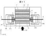
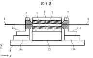
図11,12は、分離カラム交換装置を構成する分離カラム収納ホルダ移動機構及びフィッティング着脱装置の構成例を示す概略図である。図11はYZ平面における分離カラム2の中心軸での断面模式図、図12は図11の矢印53の方向から見たXY平面での断面模式図である。
11 and 12 are schematic views showing configuration examples of a separation column storage holder moving mechanism and a fitting attachment / detachment device constituting the separation column exchange device. 11 is a schematic cross-sectional view taken along the central axis of the separation column 2 in the YZ plane, and FIG. 12 is a schematic cross-sectional view taken along the XY plane as viewed from the direction of the arrow 53 in FIG.
ベース18にY軸ステージ19a,19bを配置し、Y軸ステージ19a,19bにフィッティングホルダ21a,21bを配置している。この構成により、ベース18に対しY軸方向に固定された分離カラム2に対し、第1フィッティング5、第2フィッティング7をY軸方向に駆動することが可能となる。また、ベース18にZ軸ステージ22を配置し、Z軸ステージ22に分離カラム収納ホルダ1を配置することで、ベース18に対して分離カラム2をZ軸方向に駆動することが可能となる。これらの動きにより、図3~6に示したような分離カラム交換のためのシーケンス動作が可能となる。
The Y axis stages 19a and 19b are arranged on the base 18, and the fitting holders 21a and 21b are arranged on the Y axis stages 19a and 19b. With this configuration, the first fitting 5 and the second fitting 7 can be driven in the Y-axis direction with respect to the separation column 2 fixed in the Y-axis direction with respect to the base 18. Further, by arranging the Z-axis stage 22 on the base 18 and the separation column storage holder 1 on the Z-axis stage 22, the separation column 2 can be driven in the Z-axis direction with respect to the base 18. By these movements, the sequence operation for exchanging the separation column as shown in FIGS. 3 to 6 becomes possible.
Z軸ステージ22により分離カラム2を分析ライン位置301へ移動したときの位置決めは、例えば、Z軸ステージ22の駆動にモータなどの回転機構とネジ送りの組み合わせ機構を用いた場合は、モータ回転数とそれに応じたネジピッチによる移動量を制御することで可能である。また、各種センサなどを設置し、所望位置まで駆動部材が到達した際にセンサが反応するように配置しておき、センサの反応に応じて駆動部を停止する制御でも可能である。また、プランジャなどのバネ仕掛けなどで出入り可能なボールなどの駆動部を利用したストッパ構造などでも可能である。
Positioning when the separation column 2 is moved to the analysis line position 301 by the Z-axis stage 22 is, for example, when a rotation mechanism such as a motor and a combination mechanism of screw feed are used to drive the Z-axis stage 22, the motor rotation speed This is possible by controlling the amount of movement according to the screw pitch. In addition, it is possible to perform control in which various sensors are installed so that the sensor reacts when the driving member reaches a desired position, and the driving unit is stopped according to the sensor reaction. Further, a stopper structure using a driving unit such as a ball that can be moved in and out by a spring mechanism such as a plunger is also possible.
なお、分離カラム収納ホルダ1をベース18に対してY軸方向へスライド可能なガイドを配置することで、2つのY軸ステージ19a,19bのうちどちらか一方の駆動でも分離カラム2も道連れで駆動できるので、両側のフィッティング5,7を接続することもできる(以下の各実施例についても同様)。
In addition, by arranging a guide that can slide the separation column storage holder 1 in the Y-axis direction with respect to the base 18, the separation column 2 is driven along with either of the two Y-axis stages 19 a and 19 b. Therefore, the fittings 5 and 7 on both sides can be connected (the same applies to the following embodiments).
図13は、本実施例による分離カラム交換動作の例を示すタイムシーケンス図である。分離カラム2の使用寿命回数をn回とした場合、使用回数がn回未満の所定回数を経過した時点でアラートを出す。アラートが出てから使用回数がn回に達するまでの間に予備の分離カラム2’をセットしておく。予備の分離カラム2’のセッティングは、分析ライン位置301にあって使用中の分離カラムを収納している分離カラム収納ホルダ1の接続部に予備の分離カラム2’を収納した分離カラム収納ホルダ1’の接続部をスライドさせて噛合わせることで行う。その後、分離カラム2の使用回数がn回に達した時点でY軸ステージ19a,19bを分離カラムから離間する方向に駆動し、分離カラム2から第1フィッティング5及び第2フィッティング7を開放する。解放後にZ軸ステージ22を駆動し、予備の分離カラム2’を分析ライン位置301に移動させる。その後、Y軸ステージ19a,19bを分離カラムに接近する方向に駆動し、分析ライン位置301にセットされた予備の分離カラム2’に第1フィッティング5及び第2フィッティング7を接続する。この動作により、装置を停止することなく分析中に予備カラムをセットできるので、スループットの低下を防ぐことができる。分離カラム2の使用回数のカウント作業やアラートの出力などは、例えば、データ処理部17などで行うことができる。
FIG. 13 is a time sequence diagram showing an example of separation column exchange operation according to the present embodiment. When the service life of the separation column 2 is n times, an alert is issued when a predetermined number of use times less than n has elapsed. The spare separation column 2 'is set between the time when the alert is issued and the time when the number of uses reaches n times. The setting of the spare separation column 2 ′ is the separation column storage holder 1 in which the spare separation column 2 ′ is accommodated in the connection portion of the separation column storage holder 1 that accommodates the separation column in use at the analysis line position 301. This is done by sliding the connection part of 'and meshing. Thereafter, when the number of times the separation column 2 is used reaches n times, the Y- axis stages 19a and 19b are driven in a direction away from the separation column, and the first fitting 5 and the second fitting 7 are released from the separation column 2. After releasing, the Z-axis stage 22 is driven to move the spare separation column 2 ′ to the analysis line position 301. Thereafter, the Y-axis stages 19 a and 19 b are driven in a direction approaching the separation column, and the first fitting 5 and the second fitting 7 are connected to the spare separation column 2 ′ set at the analysis line position 301. By this operation, the spare column can be set during the analysis without stopping the apparatus, so that a reduction in throughput can be prevented. The operation of counting the number of times the separation column 2 is used, the output of an alert, and the like can be performed by, for example, the data processing unit 17.
なお、本実施例の分離カラム収納ホルダ1は連続的に接続可能なので、セットする予備の分離カラム収納ホルダは複数重ねてセットすることも可能である(以下の各実施例についても同様)。
In addition, since the separation column storage holder 1 of the present embodiment can be connected continuously, a plurality of spare separation column storage holders to be set can be set in a stacked manner (the same applies to the following embodiments).
この動作を繰返し行う場合は、追加した予備の分離カラム収納ホルダの数に対応可能なストロークを有するZ軸ステージが必要となる。Z軸ステージとして、例えばベルトコンベアのようなエンドレスの駆動機構を用いれば、Z軸ステージを一方向に駆動することで分離カラムの交換動作を半永久的に繰り返すことが可能になる。
When repeating this operation, a Z-axis stage having a stroke corresponding to the number of additional separation column storage holders added is required. If an endless drive mechanism such as a belt conveyor is used as the Z-axis stage, the separation column exchange operation can be repeated semipermanently by driving the Z-axis stage in one direction.
なお、接続部8の引掛り部9a,9bは上下反対でも良い(以下の各実施例についても同様)。
Note that the hooking portions 9a and 9b of the connecting portion 8 may be upside down (the same applies to the following embodiments).
[実施例2]
実施例2では、T字型の接続部を有する分離カラム収納ホルダについて説明する。 [Example 2]
In Example 2, a separation column storage holder having a T-shaped connecting portion will be described.
実施例2では、T字型の接続部を有する分離カラム収納ホルダについて説明する。 [Example 2]
In Example 2, a separation column storage holder having a T-shaped connecting portion will be described.
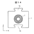
図14は、本実施例の分離カラム収納ホルダ1の構成例を示す断面模式図である。基本的な構成は図9とほぼ同様なので、相違点について説明する。本実施例の分離カラム収納ホルダ1は、接続部8の引掛り部9a,9bの断面形状をT字型とした。本構成でも図8と同様にY軸方向に移動可能、かつ、Z軸方向の動きを固定可能なので同様の効果が得られる。分離カラム交換装置は、実施例1と同様の構成とすることができる。
FIG. 14 is a schematic cross-sectional view showing a configuration example of the separation column storage holder 1 of the present embodiment. Since the basic configuration is substantially the same as in FIG. 9, the differences will be described. In the separation column storage holder 1 of the present embodiment, the cross-sectional shapes of the hook portions 9a and 9b of the connection portion 8 are T-shaped. In this configuration as well, the same effect can be obtained because the movement in the Y-axis direction and the movement in the Z-axis direction can be fixed as in FIG. The separation column exchange device can have the same configuration as in the first embodiment.
実施例2の分離カラム収納ホルダ1は、T字形状で引掛り部を構成したため製作コストを抑えられるメリットがある。
The separation column storage holder 1 of Example 2 has a merit that the manufacturing cost can be reduced because the hook portion is formed in a T shape.
[実施例3]
実施例3では、接続部にころがり部材を有する分離カラム収納ホルダについて説明する。 [Example 3]
In Example 3, a separation column storage holder having a rolling member at a connection portion will be described.
実施例3では、接続部にころがり部材を有する分離カラム収納ホルダについて説明する。 [Example 3]
In Example 3, a separation column storage holder having a rolling member at a connection portion will be described.
図15は、本実施例の分離カラム収納ホルダ1の構成例を示す断面模式図である。基本的な構成は図9とほぼ同様なので、相違点について説明する。本実施例の分離カラム収納ホルダ1は、接続部8の引掛り部9a,9bにころがり部材23を有する。本構成でも図8と同様にY軸方向に移動可能、かつ、Z軸方向の動きを固定可能なので同様の効果が得られる。分離カラム交換装置は、実施例1と同様の構成とすることができる。
FIG. 15 is a schematic cross-sectional view showing a configuration example of the separation column storage holder 1 of the present embodiment. Since the basic configuration is substantially the same as in FIG. 9, the differences will be described. The separation column storage holder 1 of the present embodiment has rolling members 23 at the hook portions 9 a and 9 b of the connection portion 8. In this configuration as well, the same effect can be obtained because the movement in the Y-axis direction and the movement in the Z-axis direction can be fixed as in FIG. The separation column exchange device can have the same configuration as in the first embodiment.
実施例3の分離カラム収納ホルダ1は、ころがりによる案内構成のため、引掛り部のY軸方向の駆動が滑らかになるメリットがある。
The separation column storage holder 1 of Example 3 has a merit that the drive in the Y-axis direction of the hooking portion is smooth because of the guide configuration by rolling.
なお、図15には凸部側の引掛り部9aにころがり部材23を配置する例を示したが、ころがり部材は凹部側の引掛り部9bに配置しても良い。
In addition, although the example which arrange | positions the rolling member 23 in the hook part 9a by the side of a convex part was shown in FIG. 15, you may arrange | position a rolling member in the hook part 9b by the side of a recessed part.
[実施例4]
実施例4では、接続部に摺動層を有する分離カラム収納ホルダについて説明する。 [Example 4]
In Example 4, a separation column storage holder having a sliding layer at a connection portion will be described.
実施例4では、接続部に摺動層を有する分離カラム収納ホルダについて説明する。 [Example 4]
In Example 4, a separation column storage holder having a sliding layer at a connection portion will be described.
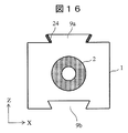
図16は、本実施例の分離カラム収納ホルダ1の構成例を示す断面模式図である。基本的な構成は図9とほぼ同様なので、相違点について説明する。本実施例の分離カラム収納ホルダ1は、接続部8の引掛り部9a,9bに摺動層24を有する。摺動層24には、フッ素樹脂や二硫化モリブデンなどの摩擦係数の低い部材のコーティング層や、そのような部材のシートを貼付けたような固体層の他、潤滑油のような液体層を採用しても良い。本構成でも図8と同様にY軸方向に移動可能、かつ、Z軸方向の動きを固定可能なので同様の効果が得られる。分離カラム交換装置は、実施例1と同様の構成とすることができる。
FIG. 16 is a schematic cross-sectional view showing a configuration example of the separation column storage holder 1 of the present embodiment. Since the basic configuration is substantially the same as in FIG. 9, the differences will be described. The separation column storage holder 1 of the present embodiment has a sliding layer 24 in the hooking portions 9 a and 9 b of the connection portion 8. The sliding layer 24 employs a coating layer of a member having a low coefficient of friction such as a fluororesin or molybdenum disulfide, a solid layer such as a sheet of such a member, or a liquid layer such as a lubricating oil. You may do it. In this configuration as well, the same effect can be obtained because the movement in the Y-axis direction and the movement in the Z-axis direction can be fixed as in FIG. The separation column exchange device can have the same configuration as in the first embodiment.
実施例4の分離カラム収納ホルダ1は、低コストで引掛り部のY軸駆動が滑らかとなるメリットがある。
The separation column storage holder 1 of Example 4 has an advantage that the Y-axis drive of the catching portion is smooth at low cost.
なお、図16では凸部側の引掛り部9aに摺動層24を配置する例を示したが、摺動層は凹部側の引掛り部9bに配置しても良い。
In addition, although the example which arrange | positions the sliding layer 24 in the hook part 9a on the convex part side was shown in FIG. 16, you may arrange | position a sliding layer in the hook part 9b on the concave part side.
[実施例5]
実施例5では、接続部にネジを有する分離カラム収納ホルダについて説明する。 [Example 5]
In Example 5, a separation column storage holder having a screw at the connection portion will be described.
実施例5では、接続部にネジを有する分離カラム収納ホルダについて説明する。 [Example 5]
In Example 5, a separation column storage holder having a screw at the connection portion will be described.
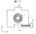
図17は、本実施例の分離カラム収納ホルダ1の構成例を示す断面模式図である。基本的な構成は図9とほぼ同様なので、相違点について説明する。本実施例の分離カラム収納ホルダ1の接続部8は、分離カラム2の長手方向に平行かつ互いに平行な2つの側面に設けられ、一方の側面に設けられた接続部としての引掛り部9aは凸部を構成し、他方の側面に設けられた接続部としての引掛り部9bは凹部を構成する。一例として、凹部は分離カラム収納ホルダ1の両端を結ぶ溝であり、凸部はその溝に挿入される段部である。2つの分離カラム収納ホルダはZ軸方向に重ね合わせ、あるいはY軸方向にスライドさせて、それぞれの接続部である凹部と凸部を嵌め合わせることで接続される。
FIG. 17 is a schematic cross-sectional view showing a configuration example of the separation column storage holder 1 of the present embodiment. Since the basic configuration is substantially the same as in FIG. 9, the differences will be described. The connection portion 8 of the separation column storage holder 1 of the present embodiment is provided on two side surfaces parallel to the longitudinal direction of the separation column 2 and parallel to each other, and a hook portion 9a as a connection portion provided on one side surface is The hook portion 9b as a connecting portion provided on the other side surface that constitutes the convex portion constitutes a concave portion. As an example, the concave portion is a groove connecting both ends of the separation column storage holder 1, and the convex portion is a step portion inserted into the groove. The two separation column storage holders are connected by being overlapped in the Z-axis direction or slid in the Y-axis direction and fitting the concave and convex portions as the respective connecting portions.
また、接続部8の引掛り部9a,9bに、Y軸方向とZ軸方向の動きを固定するための固定部材としてのネジ25を有する。ネジ25を締めることで分離カラム収納ホルダ1のY軸方向とZ軸方向の動きを固定できる。本構成でもネジ25を緩めることで図8と同様にY軸方向に移動可能なので、同様の効果が得られる。分離カラム交換装置は、実施例1と同様の構成とすることができる。
Further, the hooks 9a and 9b of the connecting part 8 have screws 25 as fixing members for fixing the movement in the Y-axis direction and the Z-axis direction. By tightening the screw 25, the movement of the separation column storage holder 1 in the Y axis direction and the Z axis direction can be fixed. Even in this configuration, by loosening the screw 25, it is possible to move in the Y-axis direction as in FIG. The separation column exchange device can have the same configuration as in the first embodiment.
実施例5の分離カラム収納ホルダ1は、ネジ締めやネジ緩めの作業工程は増えるが、接続部を噛み合わせが不要な簡単な形状とすることができるため、低コストで引掛り部を構成できる他、Y軸方向の位置決め精度が向上するメリットがある。
In the separation column storage holder 1 of the fifth embodiment, the number of screw tightening and screw loosening steps increases, but the connecting portion can be formed into a simple shape that does not require meshing, so that the hook portion can be configured at low cost. In addition, there is an advantage that the positioning accuracy in the Y-axis direction is improved.
[実施例6]
実施例6では、接続部にプランジャを有する分離カラム収納ホルダについて説明する。 [Example 6]
In Example 6, a separation column storage holder having a plunger at the connection portion will be described.
実施例6では、接続部にプランジャを有する分離カラム収納ホルダについて説明する。 [Example 6]
In Example 6, a separation column storage holder having a plunger at the connection portion will be described.
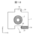
図18は、本実施例の分離カラム収納ホルダ1の構成例を示す断面模式図である。基本的な構成は図9とほぼ同様なので、相違点について説明する。本実施例の分離カラム収納ホルダ1は、接続部8の引掛り部9a,9bに、Y軸方向とZ軸方向の動きを固定するためのプランジャ26を有する。手前から予備の分離カラム収納ホルダをスライドしてセットしても、プランジャ26に内蔵したバネ27により先端に内蔵したボール28を引掛り部9aの穴部29に押付けることで、Y軸方向とZ軸方向の動きを固定できる。本構成でも図8と同様にY軸方向に移動可能、かつ、Z軸方向の動きを固定可能なので同様の効果が得られる。
FIG. 18 is a schematic cross-sectional view showing a configuration example of the separation column storage holder 1 of the present embodiment. Since the basic configuration is substantially the same as in FIG. 9, the differences will be described. The separation column storage holder 1 of the present embodiment has a plunger 26 for fixing the movement in the Y-axis direction and the Z-axis direction to the catching portions 9 a and 9 b of the connection portion 8. Even if the spare separation column storage holder is slid and set from the front, the ball 28 built in the tip is pressed against the hole 29 of the hook 9a by the spring 27 built in the plunger 26, so that The movement in the Z-axis direction can be fixed. In this configuration as well, the same effect can be obtained because the movement in the Y-axis direction and the movement in the Z-axis direction can be fixed as in FIG.
実施例6の分離カラム収納ホルダ1は、作業工程を増やすことなくY軸方向の位置決め精度を向上できるメリットがある。分離カラム交換装置は、実施例1と同様の構成とすることができる。
The separation column storage holder 1 of Example 6 has an advantage that the positioning accuracy in the Y-axis direction can be improved without increasing the number of work steps. The separation column exchange device can have the same configuration as in the first embodiment.
なお、図18では凹部側の引掛り部9bにプランジャ26を配置した例を示したが、プランジャは凸部側の引掛り部9aに配置しても良い。このとき、穴部29は凹部側の引掛り部9bの壁に設けることになる。
In addition, in FIG. 18, although the example which has arrange | positioned the plunger 26 to the catch part 9b by the side of a recessed part was shown, you may arrange | position a plunger to the catch part 9a by the side of a convex part. At this time, the hole 29 is provided in the wall of the catch portion 9b on the concave side.
以上の各実施例に示した構成の他にも、Y軸方向に移動可能でZ軸方向に固定可能な構成であれば、同様の効果が得られるので、接続部8の引掛り部9a,9bにはこれらの実施例に示した以外の構成を用いても良い。
In addition to the configuration shown in each of the above embodiments, the same effect can be obtained if the configuration is movable in the Y-axis direction and fixed in the Z-axis direction. A configuration other than those shown in these embodiments may be used for 9b.
[実施例7]
実施例7では、使用済みの分離カラム収納ホルダを廃棄する機構を有する分離カラム交換装置について説明する。分離カラム収納ホルダとしては、これまでの実施例で説明したものを用いることができる。 [Example 7]
In Example 7, a separation column exchange apparatus having a mechanism for discarding a used separation column storage holder will be described. As the separation column storage holder, those described in the above embodiments can be used.
図19,20は、本実施例の分離カラム交換装置の構成例を示す断面模式図であり、いずれもYZ平面における分離カラム2の中心軸での断面を示している。図19は予備の分離カラム収納ホルダ1’が分析ライン位置301にセットされ、それに伴い使用済み分離カラム収納ホルダ1が分析ライン位置301を外れて下側へ移動した状態を示し、図20は使用済み分離カラム収納ホルダ1を廃棄する動作を説明している。分離カラム収納ホルダ1は、上記実施例に示したように、長手方向に分離カラム同士をスライドさせて接続する構造の接続部を有する。分離カラム交換装置の基本的な構成は図11,12とほぼ同様なので、相違点について説明する。
19 and 20 are schematic cross-sectional views showing a configuration example of the separation column exchanging apparatus of the present embodiment, and both show a cross section at the central axis of the separation column 2 in the YZ plane. FIG. 19 shows a state where the spare separation column storage holder 1 ′ is set at the analysis line position 301 and the used separation column storage holder 1 is moved downwardly from the analysis line position 301. FIG. The operation of discarding the used separation column storage holder 1 is described. As shown in the above embodiment, the separation column storage holder 1 has a connection portion having a structure for connecting the separation columns by sliding them in the longitudinal direction. Since the basic configuration of the separation column exchange device is almost the same as that shown in FIGS.
本実施例の分離カラム交換装置は、使用済みの分離カラム収納ホルダ1をZ軸ステージに保持された他の分離カラム収納ホルダとの接続を外して廃棄するための分離カラム脱着部30と、脱離された使用済みの分離カラム収納ホルダ1を格納する廃棄容器34を有する。分離カラム脱着部30は、分離カラム送り方向(Z軸方向)の分析ラインより下流側で、使用済み分離カラム収納ホルダ1が移動してくる位置に配置され、Y軸方向に出入り可能な軸部31を有する。図20の矢印32のように、分離カラム脱着部30はY軸方向に軸部31を伸ばすことで、使用済みの分離カラム収納ホルダ1の端部を押し、引掛り部9に沿ってY軸方向へスライドさせて分離カラム収納ホルダ1’の接続部との接続を外して切り離し、矢印33のように廃棄容器34へ落下させる。
The separation column exchange apparatus of this embodiment includes a separation column detachment section 30 for disconnecting and discarding a used separation column storage holder 1 from another separation column storage holder held on the Z-axis stage. It has a waste container 34 for storing the separated separation column storage holder 1 that has been used. The separation column desorbing portion 30 is disposed downstream of the analysis line in the separation column feed direction (Z-axis direction) at a position where the used separation column storage holder 1 moves, and is a shaft portion that can enter and exit in the Y-axis direction. 31. As shown by an arrow 32 in FIG. 20, the separation column detachment portion 30 extends the shaft portion 31 in the Y-axis direction, thereby pushing the end of the used separation column storage holder 1 and along the hook portion 9 along the Y-axis. Slide in the direction to disconnect and disconnect the connection portion of the separation column storage holder 1 ′ and drop it into the waste container 34 as indicated by the arrow 33.
実施例7の分離カラム交換装置によると、使用済み分離カラム収納ホルダを廃棄容器にある程度蓄えておくことができるため、その都度回収する必要がなくなるメリットがある。
According to the separation column exchange device of Example 7, there is an advantage that the used separation column storage holder can be stored in the waste container to some extent, so that it is not necessary to collect each time.
[実施例8]
実施例8では、複数の分離カラムを収納する分離カラム収納ホルダについて説明する。 [Example 8]
In Example 8, a separation column storage holder that stores a plurality of separation columns will be described.
実施例8では、複数の分離カラムを収納する分離カラム収納ホルダについて説明する。 [Example 8]
In Example 8, a separation column storage holder that stores a plurality of separation columns will be described.
図21は、本実施例の分離カラム収納ホルダ1の構成例を示す断面模式図である。基本的な構成は図9とほぼ同様なので、相違点について説明する。本構成では、一つの分離カラム収納ホルダ1に、接続部の引掛り部9a,9bが設けられた2つの側面の間に複数の分離カラム2a,2b,2cを収納する。分離カラム交換装置は、実施例1と同様の構成とすることができる。
FIG. 21 is a schematic cross-sectional view showing a configuration example of the separation column storage holder 1 of the present embodiment. Since the basic configuration is substantially the same as in FIG. 9, the differences will be described. In this configuration, a plurality of separation columns 2 a, 2 b, 2 c are accommodated in one separation column storage holder 1 between two side surfaces provided with the hook portions 9 a, 9 b of the connection portion. The separation column exchange device can have the same configuration as in the first embodiment.
実施例8の分離カラム収納ホルダ1は、予備の分離カラム収納ホルダをセットする頻度を減らすメリットがある。なお、図21では3本の分離カラム2a,2b,2cを収納した例を示したが、収納する本数に関しては3本に限られない(以下の各実施例についても同様)。
The separation column storage holder 1 of Example 8 has an advantage of reducing the frequency of setting a spare separation column storage holder. In addition, although the example which accommodated three separation columns 2a, 2b, and 2c was shown in FIG. 21, it is not restricted to the number of accommodating (it is the same also about each following Example).
[実施例9]
実施例9では、密栓の開栓機構を有する分離カラム収納ホルダ及び分離カラム交換装置について説明する。 [Example 9]
In the ninth embodiment, a separation column storage holder and a separation column exchange device having a sealing plug opening mechanism will be described.
実施例9では、密栓の開栓機構を有する分離カラム収納ホルダ及び分離カラム交換装置について説明する。 [Example 9]
In the ninth embodiment, a separation column storage holder and a separation column exchange device having a sealing plug opening mechanism will be described.
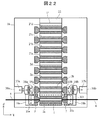
図22は、本実施例の分離カラム交換装置の構成例を示す断面模式図である。図22はYZ平面における分離カラム2の中心軸での断面を示している。分離カラム収納ホルダとしては、これまでの実施例で説明したものを用いることができる。分離カラム交換装置の基本的な構成は図11,12とほぼ同様なので、相違点について説明する。
FIG. 22 is a schematic cross-sectional view showing a configuration example of the separation column exchange apparatus of this example. FIG. 22 shows a cross section along the central axis of the separation column 2 in the YZ plane. As the separation column storage holder, those described in the above embodiments can be used. Since the basic configuration of the separation column exchange device is almost the same as that shown in FIGS.
本実施例では、分析ライン位置301の前段に予め分離カラム2に付加された密栓35a,35bを外す機構を有する。一般的に分離カラムは充填剤の性能を維持するために、内部を有機溶剤系の液体で満たし、両端を密栓で封鎖して保存される。したがって、使用の直前にこの密栓を外す必要がある。通常、密栓35a,35bは分離カラム2にネジ締め構造で固定されているため、本実施例では、矢印37a,37bで示したY軸方向の直線運動と、矢印38a,38bで示したY軸の回りの回転運動を行うことが可能な開栓機構36a,36bを有している。Z軸ステージ上に保持された分離カラムに対して開栓機構36a,36bを作用させて密栓35a,35bを外す。密栓35a,35bを外された分離カラムはZ軸ステージ22によって分析ライン位置301に搬送され、Y軸ステージ19a,19bによって第1フィッティング5及び第2フィッティング7が接続され使用に供される。
In this embodiment, there is a mechanism for removing the sealing plugs 35a and 35b previously added to the separation column 2 before the analysis line position 301. Generally, in order to maintain the performance of the packing material, the separation column is stored by filling the inside with an organic solvent-based liquid and sealing both ends with a sealing plug. Therefore, it is necessary to remove this sealing plug immediately before use. Normally, since the sealing plugs 35a and 35b are fixed to the separation column 2 with a screw tightening structure, in this embodiment, linear movement in the Y-axis direction indicated by arrows 37a and 37b and Y-axis indicated by arrows 38a and 38b are used. The plug- opening mechanisms 36a and 36b are capable of rotating around the. Opening mechanisms 36a and 36b are applied to the separation column held on the Z-axis stage to remove the sealing plugs 35a and 35b. The separation column with the sealed plugs 35a and 35b removed is conveyed to the analysis line position 301 by the Z-axis stage 22, and the first fitting 5 and the second fitting 7 are connected by the Y- axis stages 19a and 19b for use.
図23は、本実施例の分離カラム交換装置の動作例を示すタイムシーケンス図である。開栓以外の動作は基本的に図13とほぼ同様なので、相違点について説明する。図23に示すように、使用中の分離カラムの使用回数がn回となり交換時期を迎えると開栓機構36a,36bが作動し、次に使用される分離カラムの両端を封鎖している密栓35a,35bが外される。Y軸ステージは、分析ライン位置301にある分離カラムからフィッティングを開放するように駆動される。次に、Z軸ステージ22が駆動されて開栓機構によって密栓を外された分離カラムを分析ライン位置に搬送する。するとY軸ステージが駆動され、分析ライン位置に搬送された新しい分離カラムに対してフィッティングを接続する。このように、交換すべき予備の分離カラムを分析ライン位置に搬送する直前のタイミングで、開栓機構36a,36bを動作させて密栓35a,35bを外す。
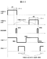
FIG. 23 is a time sequence diagram showing an operation example of the separation column exchange apparatus of this example. Since the operations other than opening are basically the same as those in FIG. 13, differences will be described. As shown in FIG. 23, when the separation column being used is used n times and the replacement time is reached, the opening mechanisms 36a and 36b are activated, and the sealing plug 35a sealing both ends of the separation column to be used next. , 35b are removed. The Y axis stage is driven to release the fitting from the separation column at the analysis line position 301. Next, the Z-axis stage 22 is driven, and the separation column that has been sealed off by the opening mechanism is transported to the analysis line position. Then, the Y-axis stage is driven to connect the fitting to the new separation column conveyed to the analysis line position. In this way, at the timing immediately before the spare separation column to be exchanged is transported to the analysis line position, the opening mechanisms 36a and 36b are operated to remove the sealing plugs 35a and 35b.
なお、図23は、分離カラムを1個だけ収納した分離カラム収納ホルダを用いるときのタイムシーケンスである。図22に示すように複数の分離カラム2a~2dを収納した分離カラム収納ホルダ1を用いる場合には、分離カラム2aの次に分析ライン位置にセットされる分離カラムは同じ分離カラム収納ホルダ中の分離カラム2bである。また、複数の分離カラムを収納した分離カラム収納ホルダを用いる場合には、アラートは分離カラム収納ホルダに収納された複数の分離カラムのうち最後の分離カラム2dの使用回数がn回未満の所定回数となったタイミングで出される。
Note that FIG. 23 is a time sequence when using a separation column storage holder that stores only one separation column. As shown in FIG. 22, when the separation column storage holder 1 storing a plurality of separation columns 2a to 2d is used, the separation column set at the analysis line position next to the separation column 2a is in the same separation column storage holder. This is a separation column 2b. When a separation column storage holder that stores a plurality of separation columns is used, the alert is a predetermined number of times that the last separation column 2d is used less than n times among the plurality of separation columns stored in the separation column storage holder. It is issued at the timing.
実施例9の分離カラム交換装置によると、予め分離カラムの密栓を外してセットする必要がなくなるメリットがある。
The separation column exchanging apparatus of Example 9 has an advantage that it is not necessary to remove and set the separation column in advance.
[実施例10]
実施例10では、繰返し動作が可能な分離カラム交換装置について説明する。 [Example 10]
In Example 10, a separation column exchange device capable of repeated operation will be described.
実施例10では、繰返し動作が可能な分離カラム交換装置について説明する。 [Example 10]
In Example 10, a separation column exchange device capable of repeated operation will be described.
図24~27は、本実施例の分離カラム交換装置の構成及び動作例を示す模式図である。図24はXY平面における分離カラム2の中心軸での断面を示し、図25~27は図24の矢印46方向から見たXZ平面における断面を示している。分離カラム収納ホルダとしては、これまでの実施例で説明したものを用いることができる。基本的な構成は図11,12とほぼ同様なので、相違点について説明する。
24 to 27 are schematic diagrams showing an example of the configuration and operation of the separation column exchange apparatus of this example. FIG. 24 shows a cross section along the central axis of the separation column 2 in the XY plane, and FIGS. 25 to 27 show cross sections in the XZ plane as viewed from the direction of the arrow 46 in FIG. As the separation column storage holder, those described in the above embodiments can be used. Since the basic configuration is almost the same as in FIGS. 11 and 12, the differences will be described.
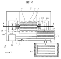
本実施例の分離カラム交換装置は、分離カラム収納ホルダ1を分離カラムの長手方向と直交するZ軸方向に移動可能に保持する枠体42、Z軸ステージ22の動きを枠体42に保持された分離カラム収納ホルダ1に伝達するための伝達部材40、伝達部材40を分離カラム収納ホルダ1に接触する位置と分離カラム収納ホルダ1から離間した位置に駆動する駆動部39を有する。
In the separation column exchanging apparatus of this embodiment, the separation column storage holder 1 is held by the frame 42 so that the movement of the frame 42 and the Z-axis stage 22 is held so as to be movable in the Z-axis direction orthogonal to the longitudinal direction of the separation column. A transmission member 40 for transmitting to the separation column storage holder 1, and a drive unit 39 for driving the transmission member 40 to a position in contact with the separation column storage holder 1 and a position away from the separation column storage holder 1.
図24,25に示すように、分離カラム収納ホルダ1は、一例として、その周囲を囲む枠体42の内部に保持されて分離カラム送り方向であるZ軸方向に移動可能になっている。Z軸方向の移動をスムーズにするために、ベース18に部材44を介して固定されている枠体42にZ軸ガイド43が配置され、分離カラム収納ホルダ1にはZ軸ガイド43が入る案内溝が設けられている。また、駆動部39の伝達部材40がZ軸方向に移動する際の妨げにならないように、枠体42には切欠き部45が設けられている。
24 and 25, as an example, the separation column storage holder 1 is held inside a frame body 42 that surrounds the separation column storage holder 1 and is movable in the Z-axis direction that is the separation column feeding direction. In order to make the movement in the Z-axis direction smooth, a Z-axis guide 43 is arranged on a frame 42 fixed to the base 18 via a member 44, and a guide for the Z-axis guide 43 to enter the separation column storage holder 1. Grooves are provided. The frame body 42 is provided with a notch 45 so as not to hinder the transmission member 40 of the drive unit 39 from moving in the Z-axis direction.
図25は、分離カラム収納ホルダ1中の分離カラム2aを用いた分析中に予備の分離カラム収納ホルダ1’をセットした状態を示している。分離カラム収納ホルダ1と分離カラム収納ホルダ1’は接続部8によって接続されている。Z軸方向に可動なZ軸ステージ22には駆動部39が配置されており、駆動部39はX軸方向に出入り可能な伝達部材40を有している。また、分離カラム収納ホルダ1の側面には伝達部材40の先端が挿入可能な穴部41が設けられている。
FIG. 25 shows a state where a spare separation column storage holder 1 ′ is set during analysis using the separation column 2 a in the separation column storage holder 1. The separation column storage holder 1 and the separation column storage holder 1 ′ are connected by a connection portion 8. A drive unit 39 is disposed on the Z-axis stage 22 movable in the Z-axis direction, and the drive unit 39 has a transmission member 40 that can enter and exit in the X-axis direction. Further, a hole 41 into which the tip of the transmission member 40 can be inserted is provided on the side surface of the separation column storage holder 1.
図25,26に示すように、伝達部材40の先端を分離カラム収納ホルダ1の穴部41に挿入した状態でZ軸ステージ22を駆動することで、分離カラム収納ホルダ1は矢印47に沿ってZ軸方向に送られる。最終的に分離カラム収納ホルダ1の中の分離カラム2a~2cは全て使用済みとなり、図26に示すように、次の分離カラム収納ホルダ1’内部の分離カラム2’aが分析ライン位置301にセットされる。その後、駆動部39により伝達部材40を駆動して、その先端を分離カラム収納ホルダ1の穴部41から引き抜き、図27に示すように、伝達部材40をZ軸ステージ22により矢印49方向に駆動し、分析ライン位置301にセットされた分離カラム収納ホルダ1’の穴部41’の位置まで戻る。その後、図19,20のような機構で使用済みの分離カラム収納ホルダ1を廃棄し、新たに予備の分離カラム収納ホルダ1”をセットすることで図25と同様の状態に戻る。
As shown in FIGS. 25 and 26, the separation column storage holder 1 is moved along the arrow 47 by driving the Z-axis stage 22 with the tip of the transmission member 40 inserted into the hole 41 of the separation column storage holder 1. Sent in the Z-axis direction. Finally, all the separation columns 2a to 2c in the separation column storage holder 1 are used, and the separation column 2′a inside the next separation column storage holder 1 ′ is placed at the analysis line position 301 as shown in FIG. Set. Thereafter, the transmission member 40 is driven by the drive unit 39, the tip thereof is pulled out from the hole 41 of the separation column storage holder 1, and the transmission member 40 is driven in the direction of the arrow 49 by the Z-axis stage 22 as shown in FIG. Then, it returns to the position of the hole 41 ′ of the separation column storage holder 1 ′ set at the analysis line position 301. Thereafter, the used separation column storage holder 1 is discarded by the mechanism as shown in FIGS. 19 and 20, and the spare separation column storage holder 1 ″ is newly set to return to the same state as in FIG.
本実施例の分離カラム交換装置の構成によれば、分離カラム交換の一連の動作を半永久的に繰り返すことが可能になるメリットがある。
The configuration of the separation column exchange device of this embodiment has an advantage that a series of separation column exchange operations can be repeated semipermanently.
[実施例11]
実施例11では、マルチカラム分析に対応可能な分離カラム収納ホルダ及び分離カラム交換装置について説明する。本実施例では、複数の分離カラムを切替えながら使用するマルチカラム分析を行う。 [Example 11]
In Example 11, a separation column storage holder and a separation column exchange device that can support multi-column analysis will be described. In this embodiment, multi-column analysis is performed while switching a plurality of separation columns.
図28は、本実施例の分析システムの構成例を示す概略図である。基本的な構成は図10とほぼ同様なので、相違点について説明する。一般に分離カラムを装置に取付けて分析を行う際、分析前に洗浄や平衡化という工程を行う。この工程は、実際には水系の液体や有機溶媒系の液体を一定時間流すことで行う。洗浄や平衡化という工程は、場合によっては分析と分析の間にも行うことがある。洗浄や平衡化の間は分析ができないのでスループットが低下する。スループット向上のために、図28に示すように複数の分離カラム502a,502bを用意し、バルブ50,51で分析用の流路を切り替え、一方の分離カラムで分析している間に他方を洗浄、平衡化するという手法を使うことがある。
FIG. 28 is a schematic diagram showing a configuration example of the analysis system of this embodiment. Since the basic configuration is substantially the same as in FIG. 10, the differences will be described. In general, when performing analysis with a separation column attached to the apparatus, washing and equilibration steps are performed before analysis. This step is actually performed by flowing an aqueous liquid or an organic solvent liquid for a certain period of time. The steps of washing and equilibration may be performed between analyzes in some cases. Throughput is reduced because analysis is not possible during washing or equilibration. In order to improve the throughput, a plurality of separation columns 502a and 502b are prepared as shown in FIG. 28, the flow paths for analysis are switched by valves 50 and 51, and the other is washed while analyzing with one separation column. Sometimes, a technique of equilibration is used.
図29は、バルブ50の一例を示す説明図であり、六方バルブの構成例を示している。図29も用いて分析システムの動作について説明する。バルブ50は流路63a,63b,63cを持つ回転子64を有する。流路63a,63b,63cには、各々、ポート65aと65b、65cと65d、65eと65fが接続されている。バルブ50には試料を導入するための配管67aの他に、洗浄や平衡化を行う溶液68を導入するための配管67bが接続されている。試料は、配管67a、ポート65a、流路63a、ポート65b、上流側配管4aを経由し、分離カラム502aへ導入される。一方、溶液68は、配管67b、ポート65d、流路63b、ポート65c、配管70、ポート65e、流路63c、ポート65f、上流側配管4bを経由し分離カラム502bへ導入される。矢印66のような回転運動で回転子64を回すことで、各流路は点線で示した63a’,63b’,63c’の位置に移動し、各々、接続先のポートが切り替わり、試料と溶液68が流れる分離カラムが反対に変わる。
FIG. 29 is an explanatory diagram showing an example of the valve 50, and shows a configuration example of a six-way valve. The operation of the analysis system will be described with reference to FIG. The valve 50 has a rotor 64 having flow paths 63a, 63b, 63c. Ports 65a and 65b, 65c and 65d, and 65e and 65f are connected to the flow paths 63a, 63b, and 63c, respectively. In addition to a pipe 67a for introducing a sample, a pipe 67b for introducing a solution 68 for cleaning and equilibration is connected to the valve 50. The sample is introduced into the separation column 502a via the pipe 67a, the port 65a, the flow path 63a, the port 65b, and the upstream pipe 4a. On the other hand, the solution 68 is introduced into the separation column 502b via the pipe 67b, the port 65d, the flow path 63b, the port 65c, the pipe 70, the port 65e, the flow path 63c, the port 65f, and the upstream pipe 4b. By rotating the rotor 64 by the rotational movement as shown by the arrow 66, each flow path moves to the positions of 63a ′, 63b ′, 63c ′ indicated by dotted lines, and the connection destination ports are switched, and the sample and the solution are switched. The separation column through which 68 flows is reversed.
バルブ51に関しては、図29の配管67a,67b、上流側配管4a,4bを、各々、下流側配管6a,6b、配管69a,69bに置き換えた構成を用いることで対応可能である。その場合は、検出器16の側ではない配管69bは廃液容器71などへ至る。なお、バルブ50,51の機能は十方バルブなどにすることで、一つのバルブに集約することもできる。
The valve 51 can be handled by using a configuration in which the pipes 67a and 67b and the upstream pipes 4a and 4b in FIG. 29 are replaced with the downstream pipes 6a and 6b and the pipes 69a and 69b, respectively. In that case, the pipe 69b that is not on the detector 16 side reaches the waste liquid container 71 and the like. The functions of the valves 50 and 51 can be integrated into one valve by using a ten-way valve or the like.
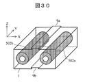
図30,31を用いて、分離カラム収納ホルダ1を交換する方式の一例について説明する。図30は、分離カラム収納ホルダ1の構成例を示す斜視図である。X軸方向はマルチアレイ方向であり、分離カラム収納ホルダ1はX軸方向に並んだ2個の分離カラム502a,502bを収納している。
An example of a method for exchanging the separation column storage holder 1 will be described with reference to FIGS. FIG. 30 is a perspective view illustrating a configuration example of the separation column storage holder 1. The X-axis direction is a multi-array direction, and the separation column storage holder 1 stores two separation columns 502a and 502b arranged in the X-axis direction.
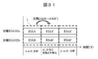
図31は、図30に示した分離カラム収納ホルダ1を用いるマルチカラム分析のタイムシーケンス図である。分離カラムA(502a)又は分離カラムB(502b)で分析後、マルチカラム分析を行う分離カラムA,B単位で収納した分離カラム収納ホルダ1を使用すると、分離カラムA,Bを同時にパラレルで交換することになるため、分離カラム収納ホルダを交換した後、新しい分離カラムA’,B’をともに洗浄、平衡化する必要があるためにスループットが低下する。
FIG. 31 is a time sequence diagram of multi-column analysis using the separation column storage holder 1 shown in FIG. After using the separation column A (502a) or the separation column B (502b), the separation columns A and B are stored in units of separation columns A and B for multi-column analysis. Therefore, after replacing the separation column storage holder, it is necessary to wash and equilibrate both new separation columns A ′ and B ′, thereby reducing the throughput.
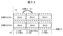
図32,33を用いて、分離カラム収納ホルダ1を交換する方式の別の例について説明する。図32は、分離カラム収納ホルダ1の構成例を示す斜視図である。X軸方向はマルチアレイ方向である。この例の分離カラム収納ホルダは、Z軸方向に複数の分離カラムを並べて収納している。図33は、マルチカラム分析のタイムシーケンス図である。図32に示すように、分離カラムA(502a)、分離カラムB(502b)それぞれの分析ラインのレーン毎に分離カラムを複数収納した分離カラム収納ホルダ1A,1Bを採用することで、例えば図33に示すように、分離カラムAで分析中に分離カラムBは洗浄、平衡化済みなので、分離カラムAを分離カラムA’に交換しても直ちに分離カラムBで分析可能となる。これと同時に分離カラムA’も洗浄、平衡化できるので、さらに次の分析ですぐに使用できる。従って、交換によるスループット低下が生じない。
32 and 33, another example of a method for exchanging the separation column storage holder 1 will be described. FIG. 32 is a perspective view illustrating a configuration example of the separation column storage holder 1. The X-axis direction is a multi-array direction. The separation column storage holder of this example stores a plurality of separation columns side by side in the Z-axis direction. FIG. 33 is a time sequence diagram of multi-column analysis. As shown in FIG. 32, by employing separation column storage holders 1A and 1B each storing a plurality of separation columns for each lane of the analysis line of separation column A (502a) and separation column B (502b), for example, FIG. As shown in FIG. 4, since the separation column B has been washed and equilibrated during the analysis with the separation column A, the separation column B can be immediately analyzed even if the separation column A is replaced with the separation column A ′. At the same time, the separation column A 'can be washed and equilibrated, so that it can be used immediately in the next analysis. Accordingly, there is no reduction in throughput due to replacement.
このように、図32に示す分離カラム収納ホルダ1では、分離カラムのマルチアレイの方向(X軸方向)と直交方向(Z軸方向)に分離カラムを複数収納する分離カラム収納ホルダを採用することで、レーン毎の移動、交換が可能となり、シームレスな分析を実現できる。
As described above, the separation column storage holder 1 shown in FIG. 32 employs a separation column storage holder that stores a plurality of separation columns in a direction orthogonal to the multi-array direction (X-axis direction) of the separation column (Z-axis direction). Therefore, movement and exchange for each lane are possible, and seamless analysis can be realized.
[実施例12]
実施例12では、温度調節部を有する分離カラム収納ホルダについて説明する。分離カラム交換装置は、これまでの実施例と同様の構成とすることができる。 [Example 12]
In Example 12, a separation column storage holder having a temperature control unit will be described. The separation column exchange device can have the same configuration as in the previous examples.
実施例12では、温度調節部を有する分離カラム収納ホルダについて説明する。分離カラム交換装置は、これまでの実施例と同様の構成とすることができる。 [Example 12]
In Example 12, a separation column storage holder having a temperature control unit will be described. The separation column exchange device can have the same configuration as in the previous examples.
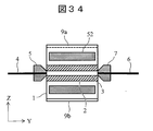
図34は、本実施例の分離カラム収納ホルダ1の構成例を示す断面模式図である。基本的な構成は図7~9とほぼ同様なので、相違点について説明する。本構成では、分離カラム収納ホルダ1に温度調節部52を内蔵している。
FIG. 34 is a schematic cross-sectional view showing a configuration example of the separation column storage holder 1 of the present embodiment. Since the basic configuration is almost the same as in FIGS. 7 to 9, differences will be described. In this configuration, the temperature adjustment unit 52 is built in the separation column storage holder 1.
一般的に分離カラムでの分析ではスループット向上や性能安定性のため分離カラムの温度を数十℃程度に調節して使用する場合がある。円筒形状が一般的な分離カラムは、カラムオーブンと呼ばれる恒温槽に入れて温度調節することが多い。カラムオーブンは空気を介しての温度調節なので、分離カラム内部を一定温度にするのが難しい。分離カラム内部に温度分布が生じると分析性能を低下させる。
In general, analysis in a separation column may be used after adjusting the temperature of the separation column to several tens of degrees Celsius in order to improve throughput and stability of performance. Separation columns, which are generally cylindrical, are often temperature controlled by placing them in a thermostat called a column oven. Since the column oven is temperature controlled via air, it is difficult to keep the inside of the separation column at a constant temperature. If the temperature distribution is generated inside the separation column, the analytical performance is degraded.
図34に示すように分離カラム収納ホルダ1に温度調節部52を搭載することで、分離カラム2の内部の充填剤3をより直接的に温度調節することが可能となる。なお、温度調節部52には加熱手段や温度モニタ手段(共に図示せず)を有する。加熱手段には各種ヒータ類の他、分離カラム収納ホルダ1の内部に電熱線を直接内蔵させる構造でも良い。温度モニタ手段には熱電対や測温抵抗体などを用いることができる。
As shown in FIG. 34, it is possible to more directly adjust the temperature of the packing material 3 in the separation column 2 by mounting the temperature adjusting unit 52 on the separation column storage holder 1. The temperature adjusting unit 52 includes a heating unit and a temperature monitoring unit (both not shown). In addition to various heaters, the heating means may have a structure in which a heating wire is directly built in the separation column storage holder 1. A thermocouple, a resistance temperature detector, etc. can be used for the temperature monitoring means.
実施例12の分離カラム収納ホルダの構成は、分析性能を向上するメリットがある。
The configuration of the separation column storage holder of Example 12 has the merit of improving analysis performance.
[実施例13]
実施例13では、分離カラムが分離カラム収納ホルダの機能を有し、温度調節部を有する構成の分離カラム収納ホルダについて説明する。分離カラム交換装置は、これまでの実施例と同様の構成とすることができる。 [Example 13]
In Example 13, a separation column storage holder having a structure in which the separation column has a function of a separation column storage holder and includes a temperature control unit will be described. The separation column exchange device can have the same configuration as in the previous examples.
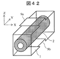
図35は、本実施例の分離カラム2の構成例を示す断面模式図である。基本的な構成は図34とほぼ同様なので、相違点について説明する。本構成では、分離カラム2に温度調節部52を内蔵している。さらに分離カラム2は分離カラム収納ホルダ1の機能を有するため、接続部としての引掛り部9a,9bを有する。つまり、分離カラム収納ホルダ1と分離カラム2が一体構造となった構成である。
FIG. 35 is a schematic cross-sectional view showing a configuration example of the separation column 2 of the present example. Since the basic configuration is substantially the same as in FIG. 34, the differences will be described. In this configuration, the temperature control unit 52 is built in the separation column 2. Furthermore, since the separation column 2 has the function of the separation column storage holder 1, the separation column 2 has hook portions 9 a and 9 b as connection portions. In other words, the separation column storage holder 1 and the separation column 2 are integrated.
実施例13の分離カラム収納ホルダ(分離カラム)の構成は、充填剤3をより直に温度調節できるため分析性能を向上するメリットがある。
The configuration of the separation column storage holder (separation column) of Example 13 has the merit of improving analysis performance because the temperature of the filler 3 can be adjusted more directly.
[実施例14]
実施例14では、分離カラム収納ホルダに異なる種類の分離カラムを収納した分離カラム収納ホルダ及び分離カラム交換装置について説明する。 [Example 14]
Example 14 describes a separation column storage holder and a separation column exchange device in which different types of separation columns are stored in a separation column storage holder.
実施例14では、分離カラム収納ホルダに異なる種類の分離カラムを収納した分離カラム収納ホルダ及び分離カラム交換装置について説明する。 [Example 14]
Example 14 describes a separation column storage holder and a separation column exchange device in which different types of separation columns are stored in a separation column storage holder.
図36は、本実施例の分離カラム収納ホルダ1及び分離カラム交換装置の構成例を示す断面模式図である。基本的な構成は図22などとほぼ同様なので、相違点について説明する。本構成では、分離カラム収納ホルダ1に異なる種類の分離カラム602,702,802,902を収納している。さらに、Z軸ステージ22は矢印54のような往復動作が可能である。分離カラム収納ホルダ1を往復駆動することにより、分離カラム602,702,802,902を並び順ではなく自由に切替えて使用することが可能となる
実施例14の分離カラム収納ホルダ及び分離カラム交換装置の構成は、異なる種類の分離カラムを切替えながら分析できるので、ランダム分析に対応できるメリットがある。 FIG. 36 is a schematic cross-sectional view showing a configuration example of the separationcolumn storage holder 1 and the separation column exchange device of the present embodiment. Since the basic configuration is almost the same as that shown in FIG. In this configuration, different types of separation columns 602, 702, 802 and 902 are stored in the separation column storage holder 1. Further, the Z-axis stage 22 can reciprocate as indicated by an arrow 54. By moving the separation column storage holder 1 back and forth, the separation columns 602, 702, 802, and 902 can be used by switching freely rather than in the order of arrangement. Separation column storage holder and separation column exchange apparatus of Example 14 This configuration has the merit of being able to cope with random analysis because the analysis can be performed while switching between different types of separation columns.
実施例14の分離カラム収納ホルダ及び分離カラム交換装置の構成は、異なる種類の分離カラムを切替えながら分析できるので、ランダム分析に対応できるメリットがある。 FIG. 36 is a schematic cross-sectional view showing a configuration example of the separation
[実施例15]
実施例15では、異なる種類の分離カラムを収納した分離カラム収納ホルダを並べて配置した分離カラム収納ホルダ及び分離カラム交換装置について説明する。 [Example 15]
Example 15 describes a separation column storage holder and a separation column exchange device in which separation column storage holders storing different types of separation columns are arranged side by side.
実施例15では、異なる種類の分離カラムを収納した分離カラム収納ホルダを並べて配置した分離カラム収納ホルダ及び分離カラム交換装置について説明する。 [Example 15]
Example 15 describes a separation column storage holder and a separation column exchange device in which separation column storage holders storing different types of separation columns are arranged side by side.
図37は、本実施例の分離カラム収納ホルダ1及び分離カラム交換装置の構成例を示す断面模式図である。基本的な構成は実施例1などとほぼ同様なので、相違点について説明する。本構成では、異なる種類の分離カラム602,702を収納した分離カラム収納ホルダ1をX軸方向に並べて配置し、X軸ステージ55は矢印56のような往復動作が可能である。よって、分離カラム収納ホルダ1をX軸方向に往復駆動することにより、異なる種類の分離カラム602,702を切替えて分析ライン位置301へ移動させることが可能となる。なお、分離カラム602,702を独立で駆動させるために、独立したZ軸ステージ22a,22bを有しても良い。
FIG. 37 is a schematic cross-sectional view showing a configuration example of the separation column storage holder 1 and the separation column exchange device of the present embodiment. Since the basic configuration is almost the same as in the first embodiment, the differences will be described. In this configuration, the separation column storage holders 1 storing different types of separation columns 602 and 702 are arranged side by side in the X-axis direction, and the X-axis stage 55 can reciprocate as indicated by an arrow 56. Therefore, by driving the separation column storage holder 1 back and forth in the X-axis direction, different types of separation columns 602 and 702 can be switched and moved to the analysis line position 301. In addition, in order to drive the separation columns 602 and 702 independently, you may have the independent Z- axis stages 22a and 22b.
実施例15の分離カラム収納ホルダ及び分離カラム交換装置の構成においても、異なる種類の分離カラムを切替えながら分析できるので、ランダム分析に対応できるメリットがある。
Also in the configuration of the separation column storage holder and the separation column exchange device of Example 15, the analysis can be performed while switching between different types of separation columns, so that there is an advantage that it can cope with random analysis.
[実施例16]
実施例16では、予備の分離カラム収納ホルダを移動させて、分析中の分離カラムと接続できる分離カラム交換装置について説明する。 [Example 16]
In the sixteenth embodiment, a separation column exchanging apparatus capable of moving a spare separation column storage holder and connecting to a separation column under analysis will be described.
実施例16では、予備の分離カラム収納ホルダを移動させて、分析中の分離カラムと接続できる分離カラム交換装置について説明する。 [Example 16]
In the sixteenth embodiment, a separation column exchanging apparatus capable of moving a spare separation column storage holder and connecting to a separation column under analysis will be described.
図38は、本実施例の分離カラム交換装置の構成例を示す断面模式図である。分離カラム収納ホルダとしては、これまでの実施例で説明したものを用いることができる。基本的な構成は図11,12とほぼ同様なので、相違点について説明する。
FIG. 38 is a schematic cross-sectional view showing a configuration example of the separation column exchange apparatus of this example. As the separation column storage holder, those described in the above embodiments can be used. Since the basic configuration is almost the same as in FIGS. 11 and 12, the differences will be described.
本実施例では、予備の分離カラム収納ホルダ1’を直接分析中の分離カラム収納ホルダ1にセットして接続するのではなく、分析ライン位置301の手前に設置された分離カラム装填ステージ57の軸部72に設けられた保持部にセットする。分離カラム装填ステージ57は、保持部にセットされた予備の分離カラム収納ホルダ1’を矢印58に沿ってY軸方向に移動させて使用中の分離カラム収納ホルダ1と接続させる。具体的には、分離カラム装填ステージ57の軸部72を伸ばすことなどで、軸部72の保持部にセットされた予備の分離カラム収納ホルダ1’を使用中の分離カラム収納ホルダ1と接続する位置までスライドさせ、互いの接続部をかみ合わせて接続する。
In this embodiment, the auxiliary separation column storage holder 1 ′ is not directly set and connected to the separation column storage holder 1 being analyzed, but the axis of the separation column loading stage 57 installed in front of the analysis line position 301. Set in the holding part provided in the part 72. The separation column loading stage 57 moves the spare separation column storage holder 1 ′ set in the holding unit in the Y-axis direction along the arrow 58 to connect to the separation column storage holder 1 in use. Specifically, the auxiliary separation column storage holder 1 ′ set in the holding portion of the shaft portion 72 is connected to the separation column storage holder 1 in use by extending the shaft portion 72 of the separation column loading stage 57. Slide to position and engage each other's connection to connect.
実施例16の分離カラム収納ホルダ及び分離カラム交換装置の構成は、分析ライン位置付近が混み入った装置構成であっても予備の分離カラムを離れた位置に容易にセットできるだけでなく、実施例12や実施例13のような温度調節部52を併用することにより、分析前に予備の分離カラムを予め温度調節できるので、分析中の分離カラムとの接続時の温度変化を小さく抑えることができるメリットがある。なお、温度調節部は、予備の分離カラム収納ホルダ1’をセットする位置周辺に設置しても同様の効果が得られる。
The configuration of the separation column storage holder and the separation column exchange apparatus of Example 16 can not only easily set the spare separation column at a distant position even if the apparatus configuration is crowded near the analysis line position. In addition, by using the temperature adjustment unit 52 as in Example 13 in advance, the temperature of the spare separation column can be adjusted in advance before analysis, so that the temperature change at the time of connection with the separation column being analyzed can be kept small. There is. It should be noted that the same effect can be obtained even if the temperature control unit is installed around the position where the spare separation column storage holder 1 'is set.
[実施例17]
実施例17では、分析後の分離カラムに密栓で閉栓する機構を有する分離カラム収納ホルダ及び分離カラム交換装置について説明する。 [Example 17]
In Example 17, a separation column storage holder and a separation column exchange device having a mechanism for closing the separation column after analysis with a tight stopper will be described.
実施例17では、分析後の分離カラムに密栓で閉栓する機構を有する分離カラム収納ホルダ及び分離カラム交換装置について説明する。 [Example 17]
In Example 17, a separation column storage holder and a separation column exchange device having a mechanism for closing the separation column after analysis with a tight stopper will be described.
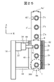
図39は、本実施例の分離カラム収納ホルダ及び分離カラム交換装置の構成例を示す断面模式図である。図39はYZ平面における分離カラム2の中心軸での断面を示している。分離カラム収納ホルダとしては、これまでの実施例で説明したものを用いることができる。基本的な構成は図22などとほぼ同様なので、相違点について説明する。
FIG. 39 is a schematic cross-sectional view showing a configuration example of the separation column storage holder and the separation column exchange device of this example. FIG. 39 shows a cross section along the central axis of the separation column 2 in the YZ plane. As the separation column storage holder, those described in the above embodiments can be used. Since the basic configuration is almost the same as in FIG. 22 and the like, the differences will be described.
本構成では、分析ライン位置301の後段に分離カラム2に密栓35a,35bを取り付ける閉栓機構を有する。閉栓機構と開栓機構は兼用の機構であり、開栓位置にあるときは開栓機構として機能し、閉栓位置にあるときは閉栓機構として機能する。図39に示した構成例では閉栓時、まず、開栓機構36a,36bがZ軸ステージ59a,59bにより矢印73a,73bに沿って、分析ライン位置301の後段の閉栓位置に移動する。そして、矢印60a,60bで示した直線運動と、矢印61a,61bで示した回転運動を行うことで、分析ライン位置から送り出されてきた使用済みの分離カラムに閉栓することが可能となる。
In this configuration, there is a closing mechanism for attaching the sealing plugs 35a and 35b to the separation column 2 after the analysis line position 301. The closing mechanism and opening mechanism are dual-purpose mechanisms that function as an opening mechanism when in the opening position and function as a closing mechanism when in the closing position. In the configuration example shown in FIG. 39, at the time of closing, first, the opening mechanisms 36a and 36b are moved to the closing position after the analysis line position 301 along the arrows 73a and 73b by the Z- axis stages 59a and 59b. Then, by performing the linear motion indicated by the arrows 60a and 60b and the rotational motion indicated by the arrows 61a and 61b, the used separation column sent from the analysis line position can be plugged.
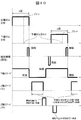
図40は、本実施例の分離カラム交換装置の動作例を説明するタイムシーケンス図である。動作は基本的に図23とほぼ同様なので、相違点である閉栓時の動作について説明する。予備の分離カラム2bが分析ライン位置301に移動すると、分析が終了した分離カラム2aが閉栓位置に移動してくる。その動作とは別に、Z軸ステージ59a,59bを駆動して開栓機構36a,36bを閉栓位置まで移動させ、その後、閉栓動作を行う。なお、開栓機構36a,36bと同様の機構を閉栓位置に有する構成であれば、Z軸ステージ59a,59bは必ずしも必要ない。開栓機構36a,36bは、開栓位置で分離カラムから取り外した密栓を閉栓位置で使用済みの分離カラムに取り付けて閉栓してもよいし、新しい密栓を使用済みの分離カラムに取り付けてもよい。
FIG. 40 is a time sequence diagram for explaining an operation example of the separation column exchange apparatus of the present embodiment. Since the operation is basically the same as that in FIG. 23, the operation at the time of closing, which is a difference, will be described. When the spare separation column 2b moves to the analysis line position 301, the separation column 2a that has been analyzed moves to the closing position. Separately from this operation, the Z- axis stages 59a and 59b are driven to move the opening mechanisms 36a and 36b to the closing position, and then the closing operation is performed. Note that the Z- axis stages 59a and 59b are not necessarily required as long as they have the same mechanism as the opening mechanisms 36a and 36b at the closing position. The opening mechanism 36a, 36b may be attached to the used separation column at the closing position by closing the sealing plug removed from the separation column at the opening position, or a new sealing plug may be attached to the used separation column. .
実施例17の分離カラム交換装置の構成は、分析後の分離カラムからの溶液による装置汚染を防ぐことができ、さらに、実施例14や実施例15のような異種カラムの切替え用途などで、分離カラムの保存性能が向上するので、分析性能が向上するメリットがある。
The configuration of the separation column exchange apparatus of Example 17 can prevent the apparatus from being contaminated by the solution from the separation column after analysis. Further, the separation column exchange apparatus can be used for switching different types of columns as in Example 14 and Example 15. Since the storage performance of the column is improved, there is an advantage that the analysis performance is improved.
[実施例18]
実施例18では、分離カラム収納ホルダにバーコードラベルを設置した分離カラム収納ホルダについて説明する。 [Example 18]
Example 18 describes a separation column storage holder in which a barcode label is installed on the separation column storage holder.
実施例18では、分離カラム収納ホルダにバーコードラベルを設置した分離カラム収納ホルダについて説明する。 [Example 18]
Example 18 describes a separation column storage holder in which a barcode label is installed on the separation column storage holder.
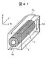
図41は、本実施例の分離カラム収納ホルダ1の構成例を示す模式図である。基本的な構成は実施例1などとほぼ同様なので、相違点について説明する。本構成では、分離カラム収納ホルダ1にバーコードラベル62を有する。分離カラム交換装置は、これまでの実施例と同様の構成とすることができる。
FIG. 41 is a schematic diagram showing a configuration example of the separation column storage holder 1 of the present embodiment. Since the basic configuration is almost the same as in the first embodiment, the differences will be described. In this configuration, the separation column storage holder 1 has a barcode label 62. The separation column exchange device can have the same configuration as in the previous examples.
本実施例の分離カラム収納ホルダ1は、バーコードラベル62のような認識手段により、分離カラムの種類や特性の他、使用履歴の管理などができるメリットがある。バーコードのようなラベルのパターンを認識するものに代えて、RFIDタグのような電波などを利用した非接触認識手段などを用いることもできる。これらの認識手段は分離カラム2に付加してもよい。これらの情報はデータ処理部17などに格納し、分離カラム2の交換時期や圧力異常などを知らせるアラートなどに利用することもできる。
The separation column storage holder 1 of the present embodiment has an advantage that the use history can be managed in addition to the type and characteristics of the separation column by the recognition means such as the barcode label 62. Instead of the one that recognizes the label pattern such as a barcode, non-contact recognition means that uses radio waves such as an RFID tag can be used. These recognition means may be added to the separation column 2. These pieces of information can be stored in the data processing unit 17 or the like, and can be used as an alert for notifying the replacement time of the separation column 2 or pressure abnormality.
[実施例19]
実施例19では、X軸方向に移動可能でZ軸方向に固定可能な接続部を有する分離カラム収納ホルダ及び分離カラム交換装置について説明する。 [Example 19]
In the nineteenth embodiment, a separation column storage holder and a separation column exchange device having a connecting portion that can move in the X-axis direction and can be fixed in the Z-axis direction will be described.
図42は、本実施例の分離カラム収納ホルダ1の構成例を示す模式図である。基本的な構成は実施例1などとほぼ同様なので、相違点について説明する。本実施例の分離カラム収納ホルダ1は、X軸方向に移動可能でZ軸方向に固定可能な接続部(引掛り部9a,9b)を有する。すなわち、本実施例の分離カラム収納ホルダ1の接続部は、分離カラム2の長手方向と直交する方向であるX軸方向に分離カラム収納ホルダ同士をスライドさせて接続する構造を有する。
FIG. 42 is a schematic diagram showing a configuration example of the separation column storage holder 1 of the present embodiment. Since the basic configuration is almost the same as in the first embodiment, the differences will be described. The separation column storage holder 1 of the present embodiment has connection portions (hooking portions 9a and 9b) that can move in the X-axis direction and can be fixed in the Z-axis direction. That is, the connection part of the separation column storage holder 1 of the present embodiment has a structure in which the separation column storage holders are slid and connected in the X-axis direction that is a direction orthogonal to the longitudinal direction of the separation column 2.
実施例19の分離カラム収納ホルダは、X軸方向からのセットや廃棄が可能となる。基本的に実施例1と同様の効果であるが、装置構成によっては本実施例の構成の方が実装が容易になる。
The separation column storage holder of Example 19 can be set or discarded from the X-axis direction. The effect is basically the same as that of the first embodiment, but the configuration of the present embodiment is easier to mount depending on the device configuration.
なお、実施例19の構成は、既に述べた分離カラム交換装置の実施例と組み合わせることも可能である。その場合、各実施例における分離カラム収納ホルダ同士のスライド方向(Y軸方向)を、実施例19のそれに相当するX軸方向に置き換えることで対応できる。
Note that the configuration of Example 19 can be combined with the example of the separation column exchange apparatus already described. In this case, the sliding direction (Y-axis direction) between the separation column storage holders in each example can be replaced with the X-axis direction corresponding to that in Example 19.
以上説明してきた各実施例の装置構成については、各々の装置構成の特徴要素を組み合わせた装置形態においても効果が得られる。また、各ステージや駆動部については、エアシリンダなどの直進機構や、カムやラックギヤのように回転を直進に変換する機構など、様々な方式を用いることができる。
As for the device configuration of each embodiment described above, an effect can be obtained even in a device configuration in which the characteristic elements of each device configuration are combined. For each stage and drive unit, various systems such as a linear mechanism such as an air cylinder and a mechanism that converts rotation into a straight line such as a cam or a rack gear can be used.
なお、本発明は上記した実施例に限定されるものではなく、様々な変形例が含まれる。例えば、上記した実施例は本発明を分かりやすく説明するために詳細に説明したものであり、必ずしも説明した全ての構成を備えるものに限定されるものではない。また、ある実施例の構成の一部を他の実施例の構成に置き換えることが可能であり、また、ある実施例の構成に他の実施例の構成を加えることも可能である。また、各実施例の構成の一部について、他の構成の追加・削除・置換をすることが可能である。
In addition, this invention is not limited to the above-mentioned Example, Various modifications are included. For example, the above-described embodiments have been described in detail for easy understanding of the present invention, and are not necessarily limited to those having all the configurations described. Further, a part of the configuration of one embodiment can be replaced with the configuration of another embodiment, and the configuration of another embodiment can be added to the configuration of one embodiment. Further, it is possible to add, delete, and replace other configurations for a part of the configuration of each embodiment.
1…分離カラム収納ホルダ
2…分離カラム
3…充填剤
4…上流側配管
5…第1フィッティング
6…下流側配管
7…第2フィッティング
8…接続部
19a,19b…Y軸ステージ
22…Z軸ステージ
23…ころがり部材
24…摺動層
25…ネジ
26…プランジャ
30…分離カラム脱着部
35a,35b…密栓
36a,36b…開栓機構
39…駆動部
40…伝達部材
42…枠体
52…温度調節部
62…バーコードラベル
301…分析ライン位置
302…予備カラムセット位置 DESCRIPTION OFSYMBOLS 1 ... Separation column storage holder 2 ... Separation column 3 ... Filler 4 ... Upstream piping 5 ... 1st fitting 6 ... Downstream piping 7 ... 2nd fitting 8 ... Connection part 19a, 19b ... Y-axis stage 22 ... Z-axis stage DESCRIPTION OF SYMBOLS 23 ... Rolling member 24 ... Sliding layer 25 ... Screw 26 ... Plunger 30 ... Separation column attachment / detachment part 35a, 35b ... Seal plug 36a, 36b ... Opening mechanism 39 ... Drive part 40 ... Transmission member 42 ... Frame body 52 ... Temperature control part 62 ... Barcode label 301 ... Analysis line position 302 ... Preliminary column set position
2…分離カラム
3…充填剤
4…上流側配管
5…第1フィッティング
6…下流側配管
7…第2フィッティング
8…接続部
19a,19b…Y軸ステージ
22…Z軸ステージ
23…ころがり部材
24…摺動層
25…ネジ
26…プランジャ
30…分離カラム脱着部
35a,35b…密栓
36a,36b…開栓機構
39…駆動部
40…伝達部材
42…枠体
52…温度調節部
62…バーコードラベル
301…分析ライン位置
302…予備カラムセット位置 DESCRIPTION OF
Claims (12)
- 充填剤を詰めた分離カラムを保持する分離カラム収納ホルダであって、
前記分離カラムの長手方向に平行な2つの側面に分離カラム収納ホルダ同士を接続するための接続部を有する、分離カラム収納ホルダ。 A separation column storage holder for holding a separation column packed with a filler,
The separation column storage holder which has a connection part for connecting separation column storage holders to two side surfaces parallel to the longitudinal direction of the separation column. - 前記接続部は前記分離カラムの長手方向に、又は当該長手方向と直交する方向に前記分離カラム収納ホルダ同士をスライドさせて接続する構造を有する、請求項1に記載の分離カラム収納ホルダ。 The separation column storage holder according to claim 1, wherein the connection portion has a structure in which the separation column storage holders are slid and connected to each other in a longitudinal direction of the separation column or in a direction orthogonal to the longitudinal direction.
- 前記接続部は前記2つの側面のうちの一方の側面に設けられた凸部と他方の側面に設けられた凹部を備え、第1の分離カラム収納ホルダの前記凹部に第2の分離カラム収納ホルダの前記凸部が入った状態で固定する固定部材を有する、請求項1に記載の分離カラム収納ホルダ。 The connecting portion includes a convex portion provided on one side surface of the two side surfaces and a concave portion provided on the other side surface, and a second separation column storage holder in the concave portion of the first separation column storage holder. The separation column storage holder according to claim 1, further comprising a fixing member that is fixed in a state where the convex portion is inserted.
- 前記2つの側面の間に前記分離カラムを複数収納する、請求項1に記載の分離カラム収納ホルダ。 The separation column storage holder according to claim 1, wherein a plurality of the separation columns are stored between the two side surfaces.
- 温度調節部を内蔵している、請求項1に記載の分離カラム収納ホルダ。 The separation column storage holder according to claim 1, which has a built-in temperature control unit.
- 前記分離カラムと一体構造である、請求項1に記載の分離カラム収納ホルダ。 The separation column storage holder according to claim 1, which has an integral structure with the separation column.
- 収納した分離カラムの長手方向に平行な2つの側面に設けられた接続部で互いに着脱自在に接続された複数の分離カラム収納ホルダを前記長手方向に対して直交する方向に搬送するZ軸ステージと、
上流側配管が固定された第1フィッティング及び下流側配管が固定された第2フィッティングをそれぞれ保持し、前記Z軸ステージによって分析ライン位置に搬送された分離カラムに対して接近する方向及び離間する方向に駆動されるY軸ステージと、
を有する分離カラム交換装置。 A Z-axis stage for conveying a plurality of separation column storage holders detachably connected to each other by connecting portions provided on two side surfaces parallel to the longitudinal direction of the stored separation column in a direction perpendicular to the longitudinal direction; ,
The first fitting to which the upstream side pipe is fixed and the second fitting to which the downstream side pipe is fixed are respectively held, and the approaching direction and the separating direction from the separation column conveyed to the analysis line position by the Z-axis stage. A Y-axis stage driven by
Separation column exchange device having - 前記接続部は第1の分離カラム収納ホルダに対して第2の分離カラム収納ホルダを前記長手方向にスライドさせて接続する構造のものであり、
前記接続部で互いに着脱自在に接続された複数の分離カラム収納ホルダから使用済みの分離カラム収納ホルダを前記長手方向にスライドさせて切り離す分離カラム脱着部を有する、請求項7に記載の分離カラム交換装置。 The connection part is configured to connect the second separation column storage holder by sliding the first separation column storage holder in the longitudinal direction;
The separation column replacement according to claim 7, further comprising a separation column detachment portion that slides and separates a used separation column storage holder from a plurality of separation column storage holders detachably connected to each other at the connection portion. apparatus. - 前記接続部は第1の分離カラム収納ホルダに対して第2の分離カラム収納ホルダを前記長手方向にスライドさせて接続する構造のものであり、
予備の分離カラム収納ホルダを保持する保持部を備え、前記保持部に保持した分離カラム収納ホルダを前記Z軸ステージに移動させる分離カラム装填ステージを有し、
前記分離カラム装填ステージにより、前記保持部に保持した分離カラム収納ホルダを前記Z軸ステージに保持されている分離カラム収納ホルダに対してスライドさせて両者を前記接続部で接続する、請求項7に記載の分離カラム交換装置。 The connection part is configured to connect the second separation column storage holder by sliding the first separation column storage holder in the longitudinal direction;
A holding unit for holding a spare separation column storage holder, and a separation column loading stage for moving the separation column storage holder held in the holding unit to the Z-axis stage;
The separation column storage stage held by the holding section is slid with respect to the separation column storage holder held by the Z-axis stage by the separation column loading stage, and the two are connected by the connection section. The separation column exchange apparatus as described. - 前記分離カラム収納ホルダを前記長手方向に直交する方向に移動可能に保持する枠体と、
前記Z軸ステージの動きを前記枠体に保持された前記分離カラム収納ホルダに伝達するための伝達部材と、
前記伝達部材を前記分離カラム収納ホルダに接触する位置と前記分離カラム収納ホルダから離間した位置に駆動する駆動部と、
を有する、請求項7に記載の分離カラム交換装置。 A frame that holds the separation column storage holder movably in a direction perpendicular to the longitudinal direction;
A transmission member for transmitting the movement of the Z-axis stage to the separation column storage holder held by the frame;
A drive unit that drives the transmission member to a position in contact with the separation column storage holder and a position spaced from the separation column storage holder;
The separation column exchange device according to claim 7, comprising: - 前記分離カラムは両端が密栓で封鎖されており、
前記Z軸ステージによって前記分析ライン位置に搬送される前に前記分離カラムの密栓を外す開栓機構を有する、請求項7に記載の分離カラム交換装置。 The separation column is sealed at both ends with a sealing plug,
The separation column exchanging apparatus according to claim 7, further comprising an opening mechanism for removing a sealing plug of the separation column before being conveyed to the analysis line position by the Z-axis stage. - 分析ライン位置にセットされて使用中の分離カラムの使用回数が使用寿命回数未満の所定回数を経過した時点でアラートを出す工程と、
前記アラートが出されてから使用回数が前記使用寿命回数に達するまでの間に、前記使用中の分離カラムを収納した第1の分離カラム収納ホルダの長手方向に平行な側面に設けられた接続部に対して予備の分離カラムを収納した第2の分離カラム収納ホルダの長手方向に平行な側面に設けられた接続部をスライドさせて両者を接続する工程と、
前記使用中の分離カラムの使用回数が前記使用寿命回数に達した時点で、当該使用中の分離カラムから、上流側配管を接続するための第1フィッティング及び下流側配管を接続するための第2フィッティングを開放する工程と、
前記第1の分離カラム収納ホルダと前記第2の分離カラム収納ホルダを接続したまま移動させ、前記予備の分離カラムを前記分析ライン位置にセットする工程と、
前記分析ライン位置にセットされた前記予備の分離カラムに前記第1フィッティング及び前記第2フィッティングを接続する工程と、
を有する分離カラム交換方法。 A step of issuing an alert when the number of times of use of the separation column that is set at the analysis line position is less than the number of times of service life has passed,
The connection portion provided on the side surface parallel to the longitudinal direction of the first separation column storage holder that stores the separation column in use, from when the alert is issued until the number of times of use reaches the number of times of use. The step of sliding the connecting portion provided on the side surface parallel to the longitudinal direction of the second separation column storage holder storing the spare separation column to connect both;
When the number of times of use of the separation column in use reaches the number of use lifetimes, the first fitting for connecting the upstream side pipe and the second for connecting the downstream side pipe from the separation column in use. Opening the fitting;
Moving the first separation column storage holder and the second separation column storage holder while being connected, and setting the spare separation column at the analysis line position;
Connecting the first fitting and the second fitting to the spare separation column set at the analysis line position;
Separation column exchange method comprising:
Priority Applications (2)
| Application Number | Priority Date | Filing Date | Title |
|---|---|---|---|
| PCT/JP2017/011822 WO2018173214A1 (en) | 2017-03-23 | 2017-03-23 | Separation column housing holder, separation column replacement device, and replacement method |
| JP2019506848A JP6796707B2 (en) | 2017-03-23 | 2017-03-23 | Separation column storage holder, separation column replacement device and replacement method |
Applications Claiming Priority (1)
| Application Number | Priority Date | Filing Date | Title |
|---|---|---|---|
| PCT/JP2017/011822 WO2018173214A1 (en) | 2017-03-23 | 2017-03-23 | Separation column housing holder, separation column replacement device, and replacement method |
Publications (1)
| Publication Number | Publication Date |
|---|---|
| WO2018173214A1 true WO2018173214A1 (en) | 2018-09-27 |
Family
ID=63585158
Family Applications (1)
| Application Number | Title | Priority Date | Filing Date |
|---|---|---|---|
| PCT/JP2017/011822 WO2018173214A1 (en) | 2017-03-23 | 2017-03-23 | Separation column housing holder, separation column replacement device, and replacement method |
Country Status (2)
| Country | Link |
|---|---|
| JP (1) | JP6796707B2 (en) |
| WO (1) | WO2018173214A1 (en) |
Cited By (2)
| Publication number | Priority date | Publication date | Assignee | Title |
|---|---|---|---|---|
| EP3922990A1 (en) * | 2021-03-28 | 2021-12-15 | MS Ekspert Sp. z o.o. | System for automatic changing and sealing of disposable chromatographic columns in high-performance liquid chromatography; measurement method and its application in the analysis of biomarker of rare disease |
| US20220155266A1 (en) * | 2019-02-27 | 2022-05-19 | Hitachi High-Tech Corporation | Analysis Apparatus Column Oven |
Citations (5)
| Publication number | Priority date | Publication date | Assignee | Title |
|---|---|---|---|---|
| US4935040A (en) * | 1989-03-29 | 1990-06-19 | The Perkin-Elmer Corporation | Miniature devices useful for gas chromatography |
| JPH034165A (en) * | 1989-05-31 | 1991-01-10 | Shimadzu Corp | Gas chromatograph cassette |
| JP2006090813A (en) * | 2004-09-22 | 2006-04-06 | Yamatake Corp | Chromatograph |
| WO2013018903A1 (en) * | 2011-08-04 | 2013-02-07 | 株式会社堀場エステック | Plate-type capillary column, capillary column unit, and chromatography using same |
| WO2017017765A1 (en) * | 2015-07-27 | 2017-02-02 | 株式会社島津製作所 | Automatic tube connection device |
-
2017
- 2017-03-23 JP JP2019506848A patent/JP6796707B2/en active Active
- 2017-03-23 WO PCT/JP2017/011822 patent/WO2018173214A1/en active Application Filing
Patent Citations (5)
| Publication number | Priority date | Publication date | Assignee | Title |
|---|---|---|---|---|
| US4935040A (en) * | 1989-03-29 | 1990-06-19 | The Perkin-Elmer Corporation | Miniature devices useful for gas chromatography |
| JPH034165A (en) * | 1989-05-31 | 1991-01-10 | Shimadzu Corp | Gas chromatograph cassette |
| JP2006090813A (en) * | 2004-09-22 | 2006-04-06 | Yamatake Corp | Chromatograph |
| WO2013018903A1 (en) * | 2011-08-04 | 2013-02-07 | 株式会社堀場エステック | Plate-type capillary column, capillary column unit, and chromatography using same |
| WO2017017765A1 (en) * | 2015-07-27 | 2017-02-02 | 株式会社島津製作所 | Automatic tube connection device |
Cited By (3)
| Publication number | Priority date | Publication date | Assignee | Title |
|---|---|---|---|---|
| US20220155266A1 (en) * | 2019-02-27 | 2022-05-19 | Hitachi High-Tech Corporation | Analysis Apparatus Column Oven |
| EP3922990A1 (en) * | 2021-03-28 | 2021-12-15 | MS Ekspert Sp. z o.o. | System for automatic changing and sealing of disposable chromatographic columns in high-performance liquid chromatography; measurement method and its application in the analysis of biomarker of rare disease |
| WO2022207577A1 (en) * | 2021-03-28 | 2022-10-06 | MS Ekspert Sp. z o.o. | System for automatic changing and sealing of disposable chromatographic columns in high-performance liquid chromatography; measurement method and its application in the analysis of biomarker of rare disease |
Also Published As
| Publication number | Publication date |
|---|---|
| JPWO2018173214A1 (en) | 2019-11-07 |
| JP6796707B2 (en) | 2020-12-09 |
Similar Documents
| Publication | Publication Date | Title |
|---|---|---|
| US8307541B2 (en) | Assembly for placing an insert into communication with an analytical chemical instrument | |
| US10036736B2 (en) | Liquid sampling valve | |
| JP6611398B2 (en) | Separation column connection device, connection method and analysis system | |
| US8900878B2 (en) | Pipetting device, modular pipetting unit, pipetting system and method for pipetting of fluid samples | |
| WO2018173214A1 (en) | Separation column housing holder, separation column replacement device, and replacement method | |
| US9079178B2 (en) | Apparatus and methods for pipetting with interchangeability among different pipette tips | |
| KR101876586B1 (en) | Fluid delivery system and apparatus to perform the same | |
| US20220091147A1 (en) | Liquid handling instrument and pipetting head for and method of aspirating and/or dispensing liquids | |
| EP3917671B1 (en) | Positive displacement pipette tip for motorized control automation or instrument system | |
| JP2021043029A (en) | Analyte drip and test apparatus | |
| WO2016157272A1 (en) | Electrophoresis device and electrophoresis method | |
| JP4216471B2 (en) | Automatic sampler injector with compression sealing part | |
| CN102203488A (en) | Fluid flow control members for use with valves | |
| US9027929B2 (en) | Fluidic processor and method of use | |
| CN111033269B (en) | Automatic analyzer | |
| CN208929660U (en) | A kind of automatic assembly equipment of laser beam modulation head assembly | |
| US20100206044A1 (en) | Coiled capillary for compensating mechanical stress | |
| CN211148679U (en) | Miniature liquid sampling device in laboratory | |
| US20190001468A1 (en) | Device for Clamping a Part to a Tool | |
| US8377716B2 (en) | Method for efficient and precise transfer of liquids | |
| US11774415B2 (en) | Metering pump for liquid chromatography | |
| KR200483917Y1 (en) | Apparatus for discharging chemical liquid | |
| KR100844989B1 (en) | Apparatus for transferring camera module | |
| US20080264001A1 (en) | System for processing cartridges | |
| JP2005255340A (en) | Tray take-out device |
Legal Events
| Date | Code | Title | Description |
|---|---|---|---|
| 121 | Ep: the epo has been informed by wipo that ep was designated in this application |
Ref document number: 17901436 Country of ref document: EP Kind code of ref document: A1 |
|
| ENP | Entry into the national phase |
Ref document number: 2019506848 Country of ref document: JP Kind code of ref document: A |
|
| NENP | Non-entry into the national phase |
Ref country code: DE |
|
| 122 | Ep: pct application non-entry in european phase |
Ref document number: 17901436 Country of ref document: EP Kind code of ref document: A1 |