WO2018168758A1 - 樹脂シート、積層樹脂シート、および樹脂組成物 - Google Patents
樹脂シート、積層樹脂シート、および樹脂組成物 Download PDFInfo
- Publication number
- WO2018168758A1 WO2018168758A1 PCT/JP2018/009483 JP2018009483W WO2018168758A1 WO 2018168758 A1 WO2018168758 A1 WO 2018168758A1 JP 2018009483 W JP2018009483 W JP 2018009483W WO 2018168758 A1 WO2018168758 A1 WO 2018168758A1
- Authority
- WO
- WIPO (PCT)
- Prior art keywords
- resin sheet
- resin
- laminated
- sheet
- ethylene
- Prior art date
- Legal status (The legal status is an assumption and is not a legal conclusion. Google has not performed a legal analysis and makes no representation as to the accuracy of the status listed.)
- Ceased
Links
Images

Classifications
-
- C—CHEMISTRY; METALLURGY
- C08—ORGANIC MACROMOLECULAR COMPOUNDS; THEIR PREPARATION OR CHEMICAL WORKING-UP; COMPOSITIONS BASED THEREON
- C08J—WORKING-UP; GENERAL PROCESSES OF COMPOUNDING; AFTER-TREATMENT NOT COVERED BY SUBCLASSES C08B, C08C, C08F, C08G or C08H
- C08J5/00—Manufacture of articles or shaped materials containing macromolecular substances
- C08J5/18—Manufacture of films or sheets
-
- C—CHEMISTRY; METALLURGY
- C08—ORGANIC MACROMOLECULAR COMPOUNDS; THEIR PREPARATION OR CHEMICAL WORKING-UP; COMPOSITIONS BASED THEREON
- C08K—Use of inorganic or non-macromolecular organic substances as compounding ingredients
- C08K3/00—Use of inorganic substances as compounding ingredients
-
- C—CHEMISTRY; METALLURGY
- C08—ORGANIC MACROMOLECULAR COMPOUNDS; THEIR PREPARATION OR CHEMICAL WORKING-UP; COMPOSITIONS BASED THEREON
- C08L—COMPOSITIONS OF MACROMOLECULAR COMPOUNDS
- C08L101/00—Compositions of unspecified macromolecular compounds
-
- C—CHEMISTRY; METALLURGY
- C08—ORGANIC MACROMOLECULAR COMPOUNDS; THEIR PREPARATION OR CHEMICAL WORKING-UP; COMPOSITIONS BASED THEREON
- C08L—COMPOSITIONS OF MACROMOLECULAR COMPOUNDS
- C08L23/00—Compositions of homopolymers or copolymers of unsaturated aliphatic hydrocarbons having only one carbon-to-carbon double bond; Compositions of derivatives of such polymers
- C08L23/02—Compositions of homopolymers or copolymers of unsaturated aliphatic hydrocarbons having only one carbon-to-carbon double bond; Compositions of derivatives of such polymers not modified by chemical after-treatment
- C08L23/04—Homopolymers or copolymers of ethene
- C08L23/08—Copolymers of ethene
Definitions
- the present invention relates to a resin sheet, a laminated resin sheet, and a resin composition.
- the multilayer ceramic capacitor is a chip-type ceramic capacitor in which a large number of dielectric layers such as titanium oxide and barium titanate and internal electrode layers are stacked. Multilayer ceramic capacitors are used in a wide range of electronic circuits because they can realize a small size and a large capacity while taking advantage of the excellent high frequency characteristics of ceramics.
- the multilayer ceramic capacitor is manufactured, for example, by the following method. First, a ceramic green sheet is formed by mixing ceramic powder and a binder (resin component). Next, a conductive paste is applied to a plurality of regions on the surface of the ceramic green sheet by screen printing or the like to form internal electrodes, and a ceramic green sheet provided with the internal electrodes is obtained. Next, a plurality of ceramic green sheets having internal electrodes are stacked and heat-pressed to form a laminated sheet. Next, the laminated sheet is cut to form a laminated body made into chips. Thereafter, the formed laminate is heated to decompose and remove the binder. Further, after sintering the ceramic powder, a terminal electrode is formed to obtain a multilayer ceramic capacitor.
- a binder resin component
- Patent Document 1 discloses a technique for suppressing the generation of such voids in the laminated sheet.
- Patent Document 2 discloses that an alkyl-modified vinyl alcohol polymer that obtains a ceramic green sheet having high bending strength, excellent workability, flexibility, and crack resistance in place of the PVA in order to improve characteristics resulting from PVA.
- a ceramic green sheet using hereinafter, sometimes abbreviated as “alkyl-modified PVA”.
- the laminate obtained by cutting the laminated sheet has a problem that the exposed end portion is fragile, which is generated by cutting. Therefore, conventionally, in order to protect the end portion, a resin composition containing a ceramic such as a dielectric ceramic is applied to the surface of the end portion, that is, a cut surface (cut surface), and a dielectric layer or the like is applied. In some cases, a method of protecting the ceramic layer by forming it separately and covering it is employed.
- the laminated body that is the application target of the resin composition is one that is cut into one row from the laminated sheet, for example, before being chipped, in addition to the chip as described above. (Those in which the chip formation sites are connected in a row) are also included.
- the resin composition containing ceramic is applied to the cut surface of the laminate, the gaps between the laminates are filled with the resin composition, and then the cut surface is covered with the ceramic layer by firing.
- the step of filling the groove such as the gap with resin is not limited to the case of forming such a ceramic layer, and may be applied in various situations. If (in other words, the covering of the cut surface) is easily possible, it is extremely useful.
- the present invention has been made in view of the above circumstances, and by cutting a laminated sheet in which a large number of ceramic green sheets and internal electrodes are alternately stacked, a plurality of chips are obtained in an aligned state. It is an object of the present invention to provide a resin sheet that can easily cover the exposed cut surface of a laminated body or a laminated body in which a plurality of chips are connected.
- This invention is made
- the present invention employs the following configuration.
- a resin sheet for embedding a groove The groove has a depth / width ratio of 0.5 or more, The resin sheet is disposed on the surface of the object to be processed so as to cover the groove, and the resin sheet is heated with respect to the object to be processed under the conditions of a temperature of 190 ° C. and a pressure of 92 kg / cm 2.
- the groove has a depth / width ratio of 0.5 or more
- the resin sheet is disposed on the surface of the object to be processed so as to cover the groove, and the resin sheet is heated with respect to the object to be processed under the conditions of a temperature of 80 ° C. and a pressure of 92 kg / cm 2.
- the first resin component is an ethylene-vinyl acetate copolymer, an ethylene- (meth) acrylic acid copolymer, an ethylene- (meth) methyl acrylate copolymer, and an ethylene-ethyl acrylate copolymer.
- (Second embodiment) (13) A resin composition containing a resin component having a melting point or glass transition temperature of less than 100 ° C. and an inorganic substance, wherein the content of the inorganic substance is 40% by volume or more. (14) The resin composition according to (13), wherein the inorganic substance is a dielectric ceramic. (15) The resin composition according to (13) or (14), wherein the resin component includes an ethylene copolymer. (16) In the dynamic viscoelasticity (DMA) measurement, the vibration frequency is 10 Hz, and the storage elastic modulus at 80 ° C. is 1.0 ⁇ 10 8 Pa or less. The resin composition as described. (17) A resin sheet comprising the resin composition according to (13), wherein the thickness is 1 ⁇ m or more.
- DMA dynamic viscoelasticity
- (meth) acrylic acid is a concept including both “acrylic acid” and “methacrylic acid”.
- the first embodiment of the present invention by cutting a laminated sheet in which a large number of ceramic green sheets and internal electrodes are alternately stacked, it is cut into a laminated body or a plurality of laminated chips.
- a resin sheet capable of easily covering the exposed cut surface of the laminated body in which the bodies are aligned.
- a resin composition and a resin sheet that can be laminated on a ceramic green sheet and are excellent in conformity to irregularities and surface smoothness.
- (First embodiment) ⁇ Laminated resin sheet>
- a first resin sheet containing a first resin component and an inorganic substance and a second resin sheet containing a second resin component are laminated, and the temperature is 80 ° C. and the shear rate is 7.6 s.
- the viscosity of the first resin sheet is V1 kPa ⁇ s and the viscosity of the second resin sheet is V2 kPa ⁇ s under the condition of ⁇ 1
- Log (V2) / Log (V1) is 0.7 to 1. It will be 4.
- the laminated resin sheet of the first embodiment can easily cover the surface of the target member or product with an inorganic layer such as a dielectric layer derived from the first resin sheet, for example.
- an inorganic layer such as a dielectric layer derived from the first resin sheet, for example.
- the resin component such as the first resin component disappears and the inorganic substance remains.
- the inorganic material is sintered to form an inorganic layer, whereby the surface of the target member or product is coated with the inorganic layer.
- a target member or product for example, a chip-formed laminate or a chip obtained by cutting a laminated sheet in which a large number of ceramic green sheets and internal electrodes are alternately stacked is cut.
- laminated body in which a plurality of previous chip formation sites are connected in a row is mentioned (in the present specification, these are collectively referred to as “laminated body” unless otherwise specified). And as a surface which an inorganic substance layer coat
- the laminated resin sheet of the present invention when used, the laminated resin sheet is arranged such that a large number of the laminated bodies arranged together are brought together and the first resin sheet is in contact with the upper surface of these laminated bodies.
- the laminated resin sheet is preferably pressurized while being heated and pressed against the laminated body. Thereby, the first resin sheet in the laminated resin sheet is indented between the laminated bodies and covers the cut surface.
- the laminated resin sheet is heat-treated at a high temperature so that the resin components such as the first resin component and the second resin component disappear, and the cut surface is covered with an inorganic layer.
- the cut surface of the laminate can be easily covered with the inorganic layer.
- the resin component is lost by the step of intruding the laminated resin sheet between the laminated bodies or by heat treatment. It may be cut into chips by cutting at a different stage.
- the reason why the laminated resin sheet of the first embodiment has such an excellent effect is that when the laminated resin sheet is pressed, the first resin sheet easily intrudes between the laminated bodies.
- the first resin sheet easily invades between the laminated bodies because the viscosity of the first resin sheet under the conditions of a temperature of 80 ° C. and a shear rate of 7.6 s ⁇ 1 in the laminated resin sheet.
- V1 kPa ⁇ s, Log (V2) / Log (V1) (this specification) when the viscosity of the second resin sheet is V2 kPa ⁇ s under conditions of a temperature of 80 ° C. and a shear rate of 7.6 s ⁇ 1
- logarithmic ratio of viscosity is within the specific range as described above.
- the inorganic layer formed using the laminated resin sheet of the first embodiment can function as a protective layer on the surface of the member or product.
- the resin sheet and the laminated resin sheet of the first embodiment will be described in more detail with reference to the drawings.
- the drawings to be referred to may show enlarged main parts for convenience, and the dimensional ratios and the like of each component are the same as the actual ones. Not always.
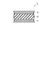
- FIG. 1 is a cross-sectional view schematically showing a first specific example of the laminated resin sheet of the first embodiment.
- the laminated resin sheet 1 shown here is configured by laminating a first resin sheet 11 and a second resin sheet 12.
- the first resin sheet 11 contains a first resin component and an inorganic substance.
- the first resin component preferably has a melting point or glass transition temperature of less than 100 ° C., and the first resin component is not particularly limited.
- the melting point or glass transition temperature of the first resin component is more preferably 99 ° C. or lower, and further preferably 95 ° C. or lower.
- the melting point or glass transition temperature of the first resin component is less than 100 ° C., the effect that the cut surface of the laminate can be easily covered with the inorganic layer is more remarkably obtained.
- fusing point or glass transition temperature of a 1st resin component is not specifically limited, It is preferable that the said melting
- transformation of the 1st resin sheet 11 at the time of manufacture of the laminated resin sheet 1 becomes higher because melting
- the first resin component preferably contains an ethylene copolymer (ethylene elastomer).
- the ethylene-based copolymer and other resins may be included. Only an ethylene-based copolymer may be used.
- “ethylene copolymer” means a copolymer having structural units derived from ethylene.
- the ethylene-based copolymer is a copolymer having a structural unit derived from ethylene and a structural unit derived from ethylene having at least a polar group as a substituent for replacing a hydrogen atom (hereinafter referred to as “polar group”). It may be referred to as an “ethylene-based copolymer having a”.
- the ethylene copolymer having the polar group has a high affinity for metal.
- Examples of the polar group in ethylene having at least the polar group described above include alkylcarbonyloxy groups such as acetyloxy group; carboxy groups; alkoxycarbonyl groups such as methoxycarbonyl groups and ethoxycarbonyl groups.
- Examples of the substituent other than the polar group in the ethylene having at least the polar group described above include an alkyl group such as a methyl group.
- Examples of the ethylene having at least a polar group include vinyl acetate; isopropenyl acetate; (meth) acrylic acid; salts of (meth) acrylic acid; methyl acrylate, ethyl acrylate, n-propyl acrylate, acrylic acid.
- the ethylene-based copolymer having a polar group is within the range not impairing the effects of the present invention, in addition to the structural unit derived from ethylene and the structural unit derived from ethylene having at least the polar group described above. You may have the other structural unit which does not correspond to either. *
- Examples of the monomer that derives the other structural unit include ⁇ -olefins other than ethylene such as propylene, n-butene, and isobutylene; acrylamide; N-methylacrylamide, N-ethylacrylamide, N, N-dimethylacrylamide, di Acrylamide derivatives such as acetone acrylamide, acrylamide propane sulfonic acid and salts thereof, dimethylaminopropyl acrylamide, acid salts of dimethylaminopropyl acrylamide, quaternary salts of dimethylaminopropyl acrylamide, N-methylol acrylamide and derivatives thereof; methacrylamide; N- Methylmethacrylamide, N-ethylmethacrylamide, methacrylamidepropanesulfonic acid and its salts, N- (3-dimethylaminopropyl) methacrylamide, N- ( -Dimethylaminopropyl) methacrylamide acid salt, quaternary salt of
- the “derivative” means a compound having a structure in which one or more hydrogen atoms of the original compound are substituted with a group other than a hydrogen atom.
- the “group” includes not only an atomic group formed by bonding a plurality of atoms but also one atom.
- the proportion of the structural unit derived from ethylene having at least the polar group is preferably 5 to 50% by mass in all the structural units. More preferably, it is mass%.
- the 1st resin sheet 11 can contain sufficient quantity of an inorganic substance which can acquire the effect by using an inorganic substance more notably.
- the effect which suppresses the blocking of the 1st resin sheet 11 becomes higher because the said ratio is 50 mass% or less.
- the proportion of the other structural unit is preferably 10% by mass or less, and may be 0% by mass in all the structural units.
- the ethylene-based copolymer having a polar group examples include an ethylene-vinyl acetate copolymer, an ethylene- (meth) acrylic acid copolymer, an ethylene- (meth) acrylic acid methyl copolymer, and And ethylene-ethyl acrylate copolymer.
- the ethylene-based copolymer having the polar group includes an ethylene-vinyl acetate copolymer (EVA), an ethylene-methyl acrylate copolymer (EMA), and an ethylene-methyl methacrylate copolymer (EMMA).
- EVA ethylene-ethyl acrylate copolymer
- EMMA ethylene-methyl methacrylate copolymer
- the ethylene-based copolymer has a functional group such as a hydroxyl group, a carboxy group, an acid anhydride group, an amino group, or a trimethoxysilyl group in the molecular chain or at the molecular chain end within a range not impairing the effects of the present invention. You may have.
- the molecular weight of the ethylene copolymer is not particularly limited. However, in order to further improve the moldability of the first resin sheet 11, the ethylene-based copolymer preferably has a weight average molecular weight of 1 ⁇ 10 4 to 2 ⁇ 10 6 .
- “weight average molecular weight” is a polystyrene equivalent value measured by gel permeation chromatography (GPC) method unless otherwise specified.
- the molecular weight dispersity (weight average molecular weight (Mw) / number average molecular weight (Mn)) of the ethylene copolymer is not particularly limited, but the stickiness of the first resin sheet 11 is reduced, and the appearance is also improved. It is preferably 1.0 to 3.5, and more preferably 1.1 to 3.0.
- Only 1 type may be sufficient as the 1st resin component which the 1st resin sheet 11 contains, and 2 or more types may be sufficient as it.
- two or more first resin components their combination and ratio can be arbitrarily selected according to the purpose.
- the first resin component comprises an ethylene-vinyl acetate copolymer, an ethylene- (meth) acrylic acid copolymer, an ethylene- (meth) methyl acrylate copolymer, and an ethylene-ethyl acrylate copolymer. It is preferable to include one or more selected ethylene-based copolymers.
- the first resin component comprises an ethylene-vinyl acetate copolymer, an ethylene- (meth) acrylic acid copolymer, an ethylene- (meth) methyl acrylate copolymer, and an ethylene-ethyl acrylate copolymer. Only one or two or more selected ethylene copolymers may be used. By using such a first resin component, the effects of the first embodiment can be obtained more significantly.
- the content of the ethylene copolymer in the first resin component is preferably 20% by mass or more, more preferably 40% by mass or more, and may be 100% by mass.
- content (mass%) of the said ethylene-type copolymer which is a 1st resin component in the 1st resin sheet 11 is the said ethylene-type copolymer weight which is the 1st resin component in the 1st resin composition mentioned later. It is the same as the content (% by mass) of the coalescence.
- a modified polyolefin polymer etc. are mentioned, for example.
- the modified polyolefin polymer include one selected from the group consisting of epoxy groups, carboxy groups, acid anhydride groups, amino groups, amide groups, oxazoline groups, hydroxyl groups, mercapto groups, ureido groups, and isocyanate groups.
- the modified polyolefin polymer etc. which have 2 or more types of functional groups in 1 molecule are mentioned.
- the modified polyolefin polymer include a copolymer of an olefin monomer and a vinyl monomer other than the olefin monomer and the vinyl monomer having the functional group, and a hydrogenated copolymer thereof. And a copolymer in which one or two or more hydrogen atoms of these copolymers are substituted with the functional group.
- the arbitrary first resin is a copolymer
- its molecular structure is not particularly limited, and may be any of a random copolymer, a block copolymer, a graft copolymer, A block copolymer or a graft copolymer is preferred.
- the arbitrary first resin contained in the first resin sheet 11 may be one type or two or more types.
- the said arbitrary 1st resin which the 1st resin sheet 11 contains is 2 or more types, those combinations and ratios can be arbitrarily selected according to the objective.
- the content of the arbitrary first resin of the first resin component is preferably 50% by mass or less, more preferably 30% by mass or less, and may be 0% by mass.
- covered with an inorganic substance layer because content of said arbitrary 1st resin is 50 mass% or less is acquired more notably.
- content (mass%) of the said arbitrary 1st resin in the 1st resin sheet 11 is the same as content (mass%) of the said arbitrary 1st resin in the 1st resin composition mentioned later. .
- the content of the first resin component in the first resin sheet 11 is preferably 6 to 20% by mass, and more preferably 9 to 14% by mass. When the content of the first resin component of the first resin sheet 11 is within such a range, the first resin sheet 11 has a good balance between strength and dielectric constant.
- the inorganic material may be a known material and is not particularly limited.
- examples of preferable inorganic materials include insulators such as glass, mica, and ceramic. By using these inorganic substances, a short circuit between the electrodes can be prevented.
- the said ceramic is not specifically limited, As a preferable thing, a dielectric ceramic is mentioned, for example.
- Preferred examples of the dielectric ceramic include barium titanate, strontium titanate, and lead zirconate titanate.
- the glass or mica is not particularly limited, but preferred examples include glass fiber, glass flakes, glass beads, silica, synthetic mica, and synthetic mica nanofiller. By using glass or mica, the mechanical strength of the first resin sheet 11 can be improved.
- the shape of the inorganic substance is not particularly limited and can be arbitrarily selected according to the purpose.
- the shape of an inorganic substance is particulates, such as spherical shape.
- the shape of an inorganic substance is plate shape or scale shape at the point which the intensity
- the particle diameter of the inorganic substance is not particularly limited, but the weighted average particle diameter of the inorganic substance is preferably 0.05 to 1.2 ⁇ m, and more preferably 0.1 to 1.0 ⁇ m.
- the weighted average particle diameter is 0.05 ⁇ m or more, the specific surface area of the inorganic substance is reduced, and the dispersity of the inorganic substance in the first resin sheet 11 and the first resin composition described later is further increased.
- the said weighted average particle diameter is 1.2 micrometers or less, the gap
- the “weighted average particle diameter of the inorganic substance” means a value calculated by measuring the particle diameter of 100 inorganic substances through observation with a microscope.
- the minor and major axes of these non-particulate inorganic substances are measured to calculate the cross-sectional area of the inorganic substance and have the same cross-sectional area as the above-mentioned cross-sectional area
- the diameter of the circle is calculated, and the weighted average particle diameter is calculated in the same manner as in the case of the particulate inorganic substance with this diameter as the particle diameter.
- the “weighted average particle diameter of the inorganic substance” includes not only the weighted average particle diameter of the particulate inorganic substance but also the weighted average particle diameter of the non-particulate inorganic substance.
- Only 1 type may be sufficient as the inorganic substance which the 1st resin sheet 11 contains, and 2 or more types may be sufficient as it.
- the combination and ratio thereof can be arbitrarily selected according to the purpose.
- the 1st resin sheet 11 may use together 2 or more groups of inorganic substances from which a weighted average particle diameter differs.
- the weighted average particle size of one group of inorganic substances is 0.05 to 0.3 ⁇ m and the other of the inorganic substances is obtained from the point that the above-described effects can be obtained more remarkably.
- the weighted average particle diameter is preferably 0.3 to 1.0 ⁇ m.
- the content of the inorganic substance in the first resin sheet 11 is preferably 40% by volume or more, more preferably 40 to 70% by volume, and particularly preferably 45 to 65% by volume.
- the first resin sheet 11 has sufficiently high flexibility and fluidity during heating, and a space in which the surface to be coated of the laminate is narrow as will be described later. Even when facing, the first resin sheet 11 can easily cover the target surface.
- the inorganic material is a dielectric ceramic, a dielectric layer having a high dielectric constant can be formed from the first resin sheet 11 covering the target surface.
- the content of the inorganic substance is 40% by volume or more, the volume of the first resin sheet 11 before sintering, which will be described later, and the volume of a layer (for example, a dielectric layer) obtained by sintering, The difference between the two becomes smaller, and such a layer can be formed more stably.
- the mechanical degree of the 1st resin sheet 11 improves more because content of the said inorganic substance is 70 volume% or less.
- content (volume%) of the inorganic substance of a 1st resin sheet becomes like this.
- it is content at normal temperature.
- “normal temperature” means a temperature that is not particularly cooled or heated, that is, a normal temperature, and examples thereof include a temperature of 15 to 25 ° C.
- the inorganic material preferably includes one or more dielectric ceramics selected from the group consisting of barium titanate, strontium titanate and lead zirconate titanate.
- the inorganic substance may be only one or more dielectric ceramics selected from the group consisting of barium titanate, strontium titanate and lead zirconate titanate.
- the first resin sheet 11 may contain other components in addition to the first resin component and the inorganic substance within a range not impairing the effects of the present invention.
- the other components include resin components other than the first resin component (sometimes referred to as “third resin component” in this specification), various additives, and the like.
- the said other component which the 1st resin sheet 11 contains may be only 1 type, and 2 or more types may be sufficient as it.
- the said other component which the 1st resin sheet 11 contains is 2 or more types, those combinations and ratios can be arbitrarily selected according to the objective.
- the third resin component (other resin components other than the first resin component) is not particularly limited and can be arbitrarily selected according to the purpose.
- the additive examples include metal salt stabilizers such as copper chloride, cuprous iodide (copper iodide (I)), copper acetate, and cerium stearate; hindered amines, hindered phenols, and sulfur-containing compounds.
- metal salt stabilizers such as copper chloride, cuprous iodide (copper iodide (I)), copper acetate, and cerium stearate; hindered amines, hindered phenols, and sulfur-containing compounds.
- Antioxidants or heat-resistant stabilizers such as acrylate-based and phosphorus-based organic compounds; UV absorbers or weathering agents such as benzophenone-based, salicylate-based, and benzotriazole-based; light stabilizers; mold release agents; lubricants; Viscosity modifiers; Colorants such as pigments and dyes; Fluorescent agents such as fluorescent pigments and fluorescent dyes; Surface treatment agents such as silane coupling agents; Coloring inhibitors; Red phosphorus, metal hydroxide flame retardants, and phosphorus-based flame retardants Flame retardants, silicone flame retardants, halogen flame retardants, flame retardants such as a mixture of the above halogen flame retardants and antimony trioxide; wood powder; rice bran powder; walnut powder; waste paper; phosphorescent pigment; borate glass, silver Antibacterial agent such as antibacterial agent or antifungal agent; Mold corrosion inhibitor such as hydrotalcite such as magnesium-aluminum hydroxyhydrate; Antistatic agent; Antiblocking agent; Surfactant; Deodorant
- the plasticizer is not particularly limited.
- the plasticizer include aromatic carboxylic acid esters, aliphatic monocarboxylic acid esters, aliphatic dicarboxylic acid esters, aliphatic tricarboxylic acid esters, phosphoric acid triesters, petroleum resins, polyalkylene glycol plasticizers, and epoxy resins.
- examples thereof include a plasticizer and a castor oil plasticizer. More specifically, examples of the plasticizer include neopentyl glycol dibenzoate, diethylene glycol dibenzoate, triethylene glycol di (2-ethylbutyrate), polyoxyethylene diacetate, polyoxyethylene di (2-ethylhexa).
- the ratio of content of a plasticizer with respect to the total content of components other than the said inorganic substance is 70 mass% or less, It is more preferable that it is 60 mass% or less, 0 mass %.
- the content ratio is 70% by mass or less, the first resin sheet 11 is improved in flexibility without impairing strength.
- the relative dielectric constant of the first resin sheet 11 is preferably 15 or more, and more preferably 20 or more.
- the relative permittivity of the first resin sheet 11 is 15 or more, for example, in the chip-formed laminate described above, a member obtained by forming a dielectric layer using the laminated resin sheet 1 or The electric capacity of the product (for example, a multilayer ceramic capacitor) is increased.
- the upper limit value of the relative dielectric constant of the first resin sheet 11 is not particularly limited, but considering the ease of manufacturing the first resin sheet 11, the relative dielectric constant of the first resin sheet 11 is 100 or less. Preferably there is.
- the relative dielectric constant can be measured using a commercially available dielectric constant measuring device (for example, manufactured by Keysight Technologies) under the condition of a frequency of 10 MHz.
- the 1st resin sheet 11 may consist of one layer (single layer), and may consist of two or more layers. When the 1st resin sheet 11 consists of multiple layers, these multiple layers may mutually be same or different, and the combination of these multiple layers is not specifically limited unless the effect of 1st embodiment is impaired.
- the thickness of the first resin sheet 11 is preferably 10 to 200 ⁇ m, and more preferably 50 to 150 ⁇ m. By the thickness of the first resin sheet 11 being 10 ⁇ m or more, the strength of the first resin sheet 11 is further improved. Moreover, the thickness of the 1st resin sheet 11 does not become excessive because the thickness of the 1st resin sheet 11 is 200 micrometers or less. For example, even when the coating target surface faces a narrow space, such as when there is a coating target surface between a large number of the stacked bodies in an aligned state, the target surface can be easily formed with the first resin sheet 11. Can be coated. When the 1st resin sheet 11 consists of multiple layers, it is good to make it the thickness of the sum total of these multiple layers be the thickness of said preferable 1st resin sheet 11. FIG.
- the second resin sheet 12 contains a second resin component.
- the said 2nd resin component will not be specifically limited if the conditions of the logarithmic ratio of the above-mentioned viscosity are satisfy
- the second resin component is a general-purpose resin such as a polyethylene (PE) resin, a polypropylene (PP) resin, a polyvinyl chloride (PVC) resin, or a thermoplastic elastomer (TPE) (hereinafter these polymers are comprehensively included). It may preferably be referred to as “second polymer”.
- the second resin component may contain a second polymer and other resin (sometimes referred to as “arbitrary second resin” in this specification), or the second polymer. It may be only.
- the second resin component includes polyethylene, low-density polyethylene, linear low-density polyethylene, polypropylene, ethylene-methyl methacrylate copolymer, ethylene-vinyl acetate copolymer, ethylene-acrylic acid.
- Ethyl copolymer ethylene-acrylic acid copolymer, styrene butadiene rubber, nitrile rubber, butadiene rubber, chloroprene rubber, ethylene propylene terpolymer, butyl rubber, isobutylene rubber, soft polyvinyl chloride, silicone resin composition, ethylene propylene rubber, Chlorinated polyethylene, acrylonitrile / butadiene / styrene (ABS) resin, acrylonitrile / acrylic rubber / styrene (AAS) resin, acrylonitrile / ethylene rubber / styrene (AES) resin, (meth) acrylic acid ester Styrene (MS) resin, styrene / butadiene / styrene (SBS) resin, and styrene / isoprene / butadiene / styrene (SIBS) resins.
- ABS
- thermoplastic elastomer for example, olefin elastomer (TPO), polyvinyl chloride elastomer (TPVC), styrene elastomer (SBC), urethane elastomer (TPU). ), Polyester elastomer (TPEE), polyamide elastomer (TPAE) and the like.
- TPO olefin elastomer
- TPVC polyvinyl chloride elastomer
- SBC styrene elastomer
- TPU urethane elastomer
- TPEE polyester elastomer
- TPAE polyamide elastomer
- the molecular weight of the second polymer is not particularly limited. However, the weight average molecular weight of the second polymer is preferably 1 ⁇ 10 4 to 2 ⁇ 10 6 in that the moldability of the second resin sheet 12 becomes better.
- the molecular weight dispersity (weight average molecular weight (Mw) / number average molecular weight (Mn)) of the second polymer is not particularly limited, but the stickiness of the second resin sheet 12 is reduced and the appearance is also good. It is preferably 1.0 to 3.5, and more preferably 1.1 to 3.0.
- the second resin component contained in the second resin sheet 12 may be only one type or two or more types.
- the 2nd resin component which the 2nd resin sheet 12 contains is 2 or more types, those combinations and ratios can be arbitrarily selected according to the objective.
- the second resin component is polyethylene, low density polyethylene, linear low density polyethylene, polypropylene, ethylene-methyl methacrylate copolymer, ethylene-vinyl acetate copolymer, ethylene-ethyl acrylate copolymer, ethylene-acrylic.
- Acid copolymer styrene butadiene rubber, nitrile rubber, butadiene rubber, chloroprene rubber, ethylene propylene terpolymer, butyl rubber, isobutylene rubber, soft polyvinyl chloride, silicone resin composition, ethylene propylene rubber, chlorinated polyethylene, acrylonitrile / butadiene / Styrene (ABS) resin, acrylonitrile / acrylic rubber / styrene (AAS) resin, acrylonitrile / ethylene rubber / styrene (AES) resin, (meth) acrylic ester / styrene (MS) resin, Rene / butadiene / styrene (SBS) resin, styrene / isoprene / butadiene / styrene (SIBS) resin, olefin elastomer (TPO), polyvinyl chloride elasto
- 1 type (s) or 2 or more types may be sufficient as a 2nd polymer.
- a 2nd resin component By using such a 2nd resin component, the effect of 1st embodiment that the cut surface of the said laminated body can be easily coat
- the content of the second polymer in the second resin component is preferably 20% by mass or more, more preferably 50% by mass or more, and may be 100% by mass.
- the mechanical degree of the 2nd resin sheet 12 improves more because content of a 2nd polymer is 20 mass or more.
- content (mass%) of the 2nd polymer which is the 2nd resin component in the 2nd resin sheet 12 is content of the 2nd polymer which is the 2nd resin component in the 2nd resin composition mentioned later. It is the same as (mass%).
- the optional second resin is a copolymer
- its molecular structure is not particularly limited, and may be any of a random copolymer, a block copolymer, a graft copolymer, A block copolymer or a graft copolymer is preferred.
- the arbitrary second resin contained in the second resin sheet 12 may be only one type or two or more types.
- the said arbitrary 2nd resin which the 2nd resin sheet 12 contains is 2 or more types, those combinations and ratios can be arbitrarily selected according to the objective.
- the content of the optional second resin in the second resin component is preferably 50% by mass or less, more preferably 30% by mass or less, and may be 0% by mass.
- the effect of 1st embodiment is acquired more notably because content of the said arbitrary 2nd resin is 50 mass% or less.
- content (mass%) of the said arbitrary 2nd resin which is a 2nd resin component in the 2nd resin sheet 12 is the said arbitrary 2nd which is a 2nd resin component in the 2nd resin composition mentioned later. It is the same as the resin content (% by mass).
- the content of the second resin component in the second resin sheet 12 is preferably 40 to 100% by mass, and more preferably 60 to 100% by mass. When the content of the second resin component of the second resin sheet 12 is in such a range, the strength of the second resin sheet 12 is further improved.
- the second resin sheet 12 may contain other components in addition to the second resin component within a range that does not impair the effects of the present invention.
- the other components include various additives.
- the said other component which the 2nd resin sheet 12 contains may be only 1 type, and 2 or more types may be sufficient as it.
- the other components contained in the second resin sheet 12 are two or more, their combination and ratio can be arbitrarily selected according to the purpose.
- Examples of the additive in the second resin sheet 12 include the same additive as the additive in the first resin sheet 11.
- the additive in the second resin sheet 12 is preferably a plasticizer in that the viscosity V2 of the second resin sheet can be easily adjusted.
- the content of the plasticizer in the second resin sheet 12 is preferably 1 to 60% by mass, and more preferably 5 to 40% by mass.
- the content of the plasticizer is 1% by mass or more, the effect obtained by using the plasticizer is more remarkably obtained.
- strength of the 2nd resin sheet 12 improves more because content of a plasticizer is 60 mass% or less.
- the 2nd resin sheet 12 may consist of one layer (single layer), and may consist of two or more layers. When the 2nd resin sheet 12 consists of multiple layers, these multiple layers may mutually be same or different, and the combination of these multiple layers is not specifically limited unless the effect of 1st embodiment is impaired.
- the thickness of the second resin sheet 12 is preferably 20 to 1000 ⁇ m, and more preferably 150 to 800 ⁇ m.
- strength of the 2nd resin sheet 12 improves more because the thickness of the 2nd resin sheet 12 is 20 micrometers or more. Moreover, since the thickness of the 2nd resin sheet 12 is 1000 micrometers or less, the thickness of the 2nd resin sheet 12 does not become excess, but a handleability becomes favorable. When the 2nd resin sheet 12 consists of multiple layers, it is good to make it the thickness of the sum total of these multiple layers be the thickness of said preferable 2nd resin sheet 12. FIG.
- the viscosity of the first resin sheet 11 under the conditions of a temperature of 80 ° C. and a shear rate of 7.6 s ⁇ 1 is V1 kPa ⁇ s
- the viscosity of the second resin sheet 12 under the same conditions Is V2 kPa ⁇ s
- Log (V2) / Log (V1) logarithmic ratio of viscosity
- the logarithmic ratio of the viscosity is in such a range, even when the surface to be covered with the first resin sheet 11 faces a narrow space, the target surface can be easily covered with the first resin sheet 11. As a result, the target surface can be easily covered with the inorganic layer.
- a laminated body obtained by cutting a laminated sheet in which a large number of ceramic green sheets and internal electrodes are alternately stacked is cut, or a plurality of chip-to-chip parts before chip formation are arranged in a row.
- the cut surface which became the bare can be easily coat
- a method for forming such an inorganic layer will be described in detail later.
- the logarithmic ratio of the viscosity is preferably 0.72 to 1.37 from the viewpoint that it becomes easier to cover the target surface with the first resin sheet 11.
- the viscosity (V1) of the first resin sheet 11 is not particularly limited as long as the logarithmic ratio of the viscosity is satisfied.
- the V1 is preferably 1500 kPa ⁇ s or less, more preferably 1200 kPa ⁇ s or less, and particularly preferably 1000 kPa ⁇ s or less.
- the target surface can be more easily covered with the first resin sheet 11 (inorganic layer).
- V1 is preferably 1 kPa ⁇ s or more, more preferably 5 kPa ⁇ s or more, and particularly preferably 10 kPa ⁇ s or more.
- the first resin sheet 11 is further improved in strength and further suppressed in deformation.
- V1 can be adjusted, for example, by adjusting the type or content of the components contained in the first resin sheet 11, or the thickness of the first resin sheet 11.
- the viscosity (V2) of the second resin sheet 12 is not particularly limited as long as the logarithmic ratio of the viscosity is satisfied.
- the V2 may be the same as or different from the V1, but is preferably equal to or less than the V1.
- the V2 is preferably 1500 kPa ⁇ s or less, more preferably 1200 kPa ⁇ s or less, and particularly preferably 900 kPa ⁇ s or less.
- V2 is 1500 kPa ⁇ s or less, it is easier to cover the target surface with the first resin sheet 11 (inorganic layer).
- V2 is preferably 0.5 kPa ⁇ s or more, more preferably 1 kPa ⁇ s or more, and particularly preferably 5 kPa ⁇ s or more.
- V2 is 0.5 kPa ⁇ s or more, the strength of the second resin sheet 12 is further improved and deformation is further suppressed.
- the V2 can be adjusted, for example, by adjusting the type or content of the component contained in the second resin sheet 12, or the thickness of the second resin sheet 12.
- V1 and V2 can be measured by the following method using, for example, a viscosity measuring device (for example, “Capillograph” manufactured by Toyo Seiki Co., Ltd.).
- a viscosity measuring device for example, “Capillograph” manufactured by Toyo Seiki Co., Ltd.
- Resin pellet The heated cylinder is filled with the first resin sheet or the second resin sheet (hereinafter abbreviated as “resin pellet”) processed into a pellet, and after sufficiently preheating, it is fixed with a constant speed plunger. Resin pellets heated to 80 ° C. are extruded from an orifice (2 mm ⁇ ⁇ 10 mmL) provided at the bottom of the cylinder, and the melt viscosity is calculated from the stress measured at that time.
- the 1st resin sheet 11 and the 2nd resin sheet 12 satisfy
- the laminated resin sheet of the present invention is not limited to the above-described embodiment, and a part of the configuration may be changed, deleted, or added without departing from the spirit of the present invention.
- the laminated resin sheet 1 shown in FIG. 1 includes the first resin sheet 11 and the second resin sheet 12, but the laminated resin sheet of the present invention may include layers (sheets) other than these. .
- FIG. 2 is a cross-sectional view schematically showing another specific example (second specific example) of the laminated resin sheet of the first embodiment. 2 and 3, the same components as those shown in FIG. 1 are denoted by the same reference numerals, and detailed description thereof is omitted.
- the laminated resin sheet 2 shown here is obtained by further laminating a third resin sheet 13 on the opposite side of the second resin sheet 12 from the side on which the first resin sheet 11 is laminated. That is, the laminated resin sheet 2 is configured by laminating the first resin sheet 11, the second resin sheet 12, and the third resin sheet 13 in this order in the thickness direction.
- the laminated resin sheet of the second specific example is obtained by further laminating one or more resin sheets on the opposite side of the second resin sheet from the side on which the first resin sheet is laminated. Also good.
- the 3rd resin sheet 13 contains resin of the grade which can maintain a sheet
- the third resin sheet 13 may contain only a resin component (sometimes referred to as “third resin component” in this specification), or a resin component (third resin component) and the same. You may contain components other than. What is necessary is just to select the content component of the 3rd resin sheet 13 suitably according to the objective.
- the third resin component is not particularly limited, and may be, for example, the same as or different from the resin component mentioned as the first resin component or the second resin component.
- the 3rd resin component and the other component which the 3rd resin sheet 13 contains all may be only 1 type and 2 or more types may be sufficient as it.
- the third resin component and the other components contained in the third resin sheet 13 are two or more, the combination and ratio thereof can be arbitrarily selected according to the purpose.
- the third resin sheet 13 may be surface-treated.
- Examples of such third resin sheet 13 include a release sheet in which one surface or both surfaces of the resin sheet are subjected to a release treatment.
- Preferable examples of the third resin component contained in the release sheet include polyethylene terephthalate (PET).
- PET polyethylene terephthalate
- the release treatment of the release sheet can be performed using a known release treatment agent such as a silicone treatment agent.
- the third resin sheet 13 is preferably arranged so that at least the release treatment surface is in contact with the second resin sheet 12. .
- the 3rd resin sheet 13 may consist of one layer (single layer), and may consist of two or more layers. When the 3rd resin sheet 13 consists of multiple layers, these multiple layers may mutually be same or different. The combination of these multiple layers is not particularly limited as long as the effects of the present invention are not impaired.
- the thickness of the third resin sheet 13 may be appropriately selected according to the type of the third resin sheet 13, but it is usually preferably 12 to 100 ⁇ m.
- the laminated resin sheet of the present invention is not limited to the above-described embodiment, and a part of the configuration may be changed, deleted, or added without departing from the spirit of the present invention.
- the laminated resin sheet of the first embodiment can be manufactured, for example, by laminating a first resin sheet and a second resin sheet.
- a 1st resin sheet can be manufactured by shape
- the second resin sheet is formed into a sheet shape from the second resin component or the second resin component and, if necessary, other components other than the second resin component. Can be manufactured.
- the ratio of the content (parts by mass) of a specific component other than the solvent to the total content (parts by mass) of all components other than the solvent is the specific value of the first resin sheet. It becomes the same as the content (mass%) of one component.
- the ratio of the content (parts by mass) of one specific component other than the solvent to the total content (parts by mass) of all components other than the solvent in the second resin composition is the above-mentioned specification of the second resin sheet. It becomes the same as the content (mass%) of one component.
- the first resin composition is, for example, a resin component such as the first resin component is heated to a temperature equal to or higher than the melting point or glass transition temperature to be in a molten state (liquid state) or a rubber state. Depending on the above, it can be produced by adding and kneading non-resin components such as other components.
- the second resin composition is prepared by heating a resin component such as the second resin component to a temperature equal to or higher than the melting point or the glass transition temperature to obtain a molten state (liquid state) or a rubber state. And it can manufacture by adding non-resin components, such as said other component, to this, and knead
- the method of heating the resin component until the temperature reaches the melting point or the glass transition temperature or higher is not particularly limited, and a known method can be applied.
- a method of heating using a closed kneader, a so-called internal mixer is preferred.
- the method of adding the non-resin component to the resin component in a molten state or a rubber state and kneading is not particularly limited, and a known method can be applied.
- a kneading method using a kneader such as an open roll, a single screw extruder, a twin screw kneader, a kneader or a Banbury mixer is preferred.
- the first resin composition or the second resin composition obtained as a kneaded product after kneading can be made into a pellet shape or a tablet shape by, for example, further granulating or cooling treatment. .
- the method of molding the first resin composition into a sheet is not particularly limited, but specific examples include a method of molding using an extrusion apparatus equipped with a T die. .
- the method of forming the second resin component or the second resin composition into a sheet shape during the production of the second resin sheet is not particularly limited, but as an example, an extrusion device equipped with a T die is used. And the like.
- the lamination of the first resin sheet and the second resin sheet may be performed by a known method.
- the laminated resin sheet of the first embodiment is obtained by laminating these sheets by thermal lamination or the like.
- the laminated resin sheet one or more resins on the opposite side of the second resin sheet from the side on which the first resin sheet is laminated, such as the one laminated with the third resin sheet as described above
- seat can be manufactured with the following method, for example. That is, first, the one or more resin sheets (for example, the third resin sheet) are manufactured by the same method as that for the first resin sheet or the second resin sheet. At this time, the one or more resin sheets (for example, the third resin sheet) are resin compositions (for example, the third resin composition) in the same manner as the first resin composition except that the blending components are different. It can manufacture by using this resin composition.
- the step of laminating the one or more resin sheets on the side of the second resin sheet on the side where the first resin sheet is laminated or the side opposite to the side on which the first resin sheet is to be laminated In the method, it is added at an appropriate timing. Thereby, the target laminated resin sheet can be manufactured. Alternatively, when the first resin sheet and the second resin sheet are laminated as described above, the target laminated resin sheet can also be produced by laminating the one or more resin sheets at the same time.
- the first resin sheet, the second resin sheet, and the third resin sheet can be laminated at any timing.
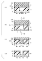
- FIG. 3 is a cross-sectional view for schematically explaining an example of a method of using the laminated resin sheet 1 shown in FIG.
- the case where the chip-formed laminated body described above is a usage target of the laminated resin sheet will be described.
- the laminated resin sheet When the laminated resin sheet is used, first, as shown in FIG. 3A, the plurality of laminated bodies 9 are grouped together, and the first resin sheet 11 is formed on the first surface 9a which is the exposed surface.
- the laminated resin sheet 1 is superposed on the laminated body 9 so as to come into contact. Thereby, the 1st laminated structure 71 which is a laminated body of the some laminated body 9 and the laminated resin sheet 1 is formed.
- the first laminated structure 71 is supported by the supporting member 6 on the laminated body 9 side, and the first surface 9a of the laminated body 9 is a surface opposite to the side supported by the supporting member 6. (Exposed surface).
- the plurality of laminates 9 are obtained by cutting a laminate sheet in which a large number of ceramic green sheets and internal electrodes (both not shown) are alternately stacked, for example, a chip-formed laminate. Yes, they are aligned by cutting. Moreover, all the side surfaces 9c of the laminated body 9 are exposed cut surfaces newly generated by cutting the laminated sheet, and the end portions of the laminated body 9 including the cut surfaces 9c are brittle. .
- the plurality of laminated bodies 9 are arranged adjacent to each other with the gap 8 generated by the cutting therebetween, and the cut surfaces 9c of the laminated bodies 9 face each other between the laminated bodies 9.
- the laminated body 9 may be a laminated body obtained by cutting the laminated sheet and in a state in which a plurality of pre-chip formation sites are connected in a row. Such a laminated body Are aligned by cutting.
- the first laminated structure 71 is then added in the lamination direction of the laminated body 9 and the laminated resin sheet 1 (in other words, in the thickness direction of the first laminated structure 71). Press.
- the pressurization at this time applies pressure from both sides of the laminated resin sheet 1 side and the laminated body 9 side of the first laminated structure 71 (in the direction of the arrow P1 and
- the pressure may be applied from the laminated resin sheet 1 side without applying pressure from the laminated body 9 side of the first laminated structure 71 (only in the arrow P1 direction).
- the pressure may be applied), or pressure is applied from the laminated body 9 side without applying pressure from the laminated resin sheet 1 side of the first laminated structure 71 (pressure is applied only in the direction of arrow P2). You may go by.
- the laminated resin sheet 1 is pressed, and as shown in FIG.3 (c), the 1st resin sheet 11 in the laminated resin sheet 1 is the laminated body 9. As shown in FIG. It intrudes into the space 8 between them and covers the cut surface 9c. As described above, the first resin sheet 11 is easily inserted into the gap 8 by simply pressurizing the first laminated structure 71 and covers the cut surface 9c of the laminated body 9. This is because the second resin sheet 12 exists adjacent to the first resin sheet 11 in addition to the 11 having appropriate characteristics.
- the logarithmic ratio of the viscosity (Log (V2) / Log (V1)) specified by the viscosity (V1) of the first resin sheet and the viscosity (V2) of the second resin sheet is 0.7 to 1. By being within the specific range of 4, such an excellent effect is exhibited.
- the 2nd resin sheet 12 when the 1st resin sheet 11 intrudes into the space
- the second resin sheet 12 is depressed to a depth of half or more of the gap 8.
- the pressurization of the first laminated structure 71 can be performed by a known method.
- both surfaces of the first laminated structure 71 that is, the surface of the laminated body 9 opposite to the side on which the first resin sheet 11 is provided (referred to as “second surface” in this specification).
- 9b and a surface of the second resin sheet 12 opposite to the side on which the first resin sheet 11 is provided (in this specification, sometimes referred to as “first surface”) 12a The first laminated structure 71 can be pressurized by placing (laminating) a pressure plate for applying pressure on one or both via a buffer sheet and applying pressure to the pressure plate.
- the buffer sheet is for suppressing damage to the laminated resin sheet 1 during pressurization.
- a release sheet may be further disposed (laminated) between the first laminated structure 71 and the buffer sheet.
- the release sheet in this case is for preventing the first laminated structure 71 and the buffer sheet from sticking, for example, one or both surfaces of the resin film are subjected to release treatment.
- the resin film include a polyethylene terephthalate (PET) film.
- PET polyethylene terephthalate
- mold release process what is performed using well-known mold release processing agents, such as a silicone processing agent, etc. are mentioned, for example.
- the release sheet the same one as described above as the third resin sheet 13 may be mentioned.
- pressurization of the laminated resin sheet 1 using the release sheet means the same as the pressurization of the laminated resin sheet 2 when the third resin sheet 13 is a release sheet.
- a structure in which at least a buffer sheet and a pressure plate are stacked on the first stacked structure is referred to as a “second stacked structure”.
- the pressurization of the first laminated structure 71 is preferably performed while heating at least the laminated resin sheet 1, and may be performed while heating the entire laminated resin sheet 1 or the entire first laminated structure 71.
- the heating temperature at the time of pressurization may be appropriately adjusted in consideration of the melting points or glass transition temperatures of the first resin component and the second resin component, but is usually preferably 70 to 100 ° C.
- the pressure at the time of pressurization of the first laminated structure 71 may be appropriately adjusted in consideration of the heating temperature at the time of pressurization, the type of the laminated resin sheet 1, etc., but is usually 50 to 1000 kg / cm 2 . Preferably there is.
- the pressurization time of the first laminated structure 71 may be appropriately adjusted in consideration of the heating temperature and pressure during pressurization, but it is usually preferably 1 to 30 minutes.
- the resin such as the first resin component and the second resin component is then heated by heating the laminated resin sheet 1 in a state of being indented into the gap portion 8 in this way.
- the component disappears and the inorganic substance remains.
- This inorganic material can be sintered and forms an inorganic layer.
- the inorganic layer 10 is formed from the first resin sheet 11 and the second resin sheet 12 disappears, the cut surface 9c of the laminate 9 is covered with the inorganic layer 10 as shown in FIG. Is done. Since the inorganic layer 10 is formed only by heat-treating the laminated resin sheet 1 at a high temperature, as a result, the cut surface 9 c of the laminate 9 can be easily covered with the inorganic layer 10.
- the inorganic layer 10 is also formed on the first surface 9 a and the support member 6 of the laminate 9. However, the extra inorganic layer 10 is provided at a place where coating with the inorganic layer 10 is unnecessary. May be removed as appropriate.
- the laminated body 9 in an aligned state immediately after cutting of the laminated sheet can be cut without performing complicated operations such as changing its orientation. 9c can be easily covered with the inorganic layer 10.
- a resin sheet for embedding a groove wherein the groove has a depth / width ratio of 0.5 or more, and covers the groove on a surface of the object to be processed having the groove.
- a resin sheet is placed and the resin sheet is pressed against the object to be processed under the conditions of a temperature of 190 ° C. and a pressure of 92 kg / cm 2 , the resin sheet is indented and the groove is embedded.
- a possible resin sheet (in this specification, sometimes referred to as a “fourth resin sheet”) is a novel one.
- the fourth resin sheets those containing an inorganic substance similar to the inorganic substance in the first resin sheet can be included in the first resin sheet.
- the resin sheet is a resin sheet for embedding a groove, and has a viscosity V5 of 1500 kPa ⁇ s or less under the conditions of a temperature of 80 ° C. and a shear rate of 7.6 s ⁇ 1.
- the resin sheet is disposed so as to cover the groove on the surface of the object to be processed having the groove having a width ratio of 0.5 or more, and under the conditions of a temperature of 80 ° C. and a pressure of 92 kg / cm 2 ,
- the resin sheet is inserted into the groove and can be embedded (referred to as “fifth resin sheet” in this specification).
- those containing an inorganic substance similar to the inorganic substance in the first resin sheet can be included in the first resin sheet.
- the 1st resin sheet in the above-mentioned laminated resin sheet is also a novel thing.
- resin sheet when each of the first resin sheet, the fourth resin sheet, and the fifth resin sheet is handled independently, these resin sheets may be collectively referred to as “resin sheet”.
- resin sheet The simple description of “resin sheet” does not mean the above-mentioned laminated resin sheet unless otherwise specified.
- any of the resin sheets (first resin sheet, fourth resin sheet, and fifth resin sheet) can be used in the same manner as in the case of the laminated resin sheet. In this case, the grooves between the laminated bodies are easily embedded. There is an effect.
- the resin sheet is stacked on the upper surface of the laminated bodies so as to cover the grooves between the laminated bodies.
- the resin sheet By placing the resin sheet, pressing the resin sheet preferably while heating, and pressing the resin sheet, the resin sheet intrudes into a groove between the stacked bodies and embeds the groove.
- these resin sheets contain an inorganic substance, the resin component (for example, the first resin component in the case of the first resin sheet) is then lost by heat-treating the resin sheet in such a state at a high temperature.
- the groove can be filled with an inorganic layer.
- the groove of the laminate can be easily embedded with the resin sheet or the inorganic layer.
- a multilayer ceramic capacitor or the like can be manufactured from the laminate in which the groove is embedded with an inorganic layer (the cut surface is covered with an inorganic layer).
- the resin sheet in the laminate in which the groove is embedded with the resin sheet, can be, for example, a protective layer having the cut surface, that is, the resin sheet can be used as a protective sheet.
- the groove is formed with a resin sheet.
- Chips may be formed by cutting at the stage of embedding or the stage where the resin component is eliminated by heat treatment.
- the resin sheet embedded in the groove may be cut at the time of cutting such a laminate, or may be heat-treated at a high temperature at any timing before or after cutting. When the resin sheet does not contain an inorganic substance, the resin sheet can be completely eliminated by heat treatment at a high temperature.
- the laminated resin sheet 1 (first resin sheet 11 and first resin sheet 11) 2 resin sheet 12) is replaced with a single resin sheet.
- the resin sheet has a much better groove embedding property than the conventional resin sheet. ing.
- the ratio of depth / width is preferably 0.5 or more, and preferably 0.5 to 20. Is more preferable, and 1 to 15 is particularly preferable. When the ratio is 0.5 or more, the groove filling effect is further improved. On the other hand, when the ratio is 20 or less, it is not necessary to increase the flowability (for example, V1 or V5, or V4 described later) of the resin sheet more than necessary, and the strength of the resin sheet at room temperature. Will improve.
- the fourth resin sheet can have the same configuration as the first resin sheet except that the inorganic substance is not an essential component, and the component of the fourth resin sheet is the same as the component of the first resin sheet.
- the resin component contained in the fourth resin sheet include polyolefins such as polypropylene, polystyrene, and 4-methyl-1-pentene; derivatives of the polyolefins, and the like.
- the 4th resin sheet containing an inorganic substance may be the same as the 1st resin sheet, and may differ.
- the fourth resin sheet preferably has a viscosity V4 of 1 to 1500 kPa ⁇ s, more preferably 1 to 1200 kPa ⁇ s under conditions of a temperature of 190 ° C. and a shear rate of 7.6 s ⁇ 1.
- the pressure is particularly preferably 1000 kPa ⁇ s, and may be any of 1 to 500 kPa ⁇ s, 1 to 250 kPa ⁇ s, 1 to 120 kPa ⁇ s, and 1 to 60 kPa ⁇ s, for example.
- V4 is 1500 kPa ⁇ s or less, the groove filling property is further improved.
- the use temperature of the fourth resin sheet is not limited to 190 ° C., and the use temperature can be arbitrarily set according to the purpose.
- the V4 can be adjusted, for example, by adjusting the type or content of the component contained in the fourth resin sheet, the thickness of the fourth resin sheet, or the like.
- the fifth resin sheet can have the same configuration as the first resin sheet except that the inorganic substance is not an essential component, and the component of the fifth resin sheet includes the component of the first resin sheet and The same can be mentioned.
- the fifth resin sheet containing the inorganic substance may be the same as or different from the first resin sheet.
- V5 is 1500 kPa * s or less, and it is preferable that it is the same range as said V1. That is, the V5 is preferably 1200 kPa ⁇ s or less, and more preferably 1000 kPa ⁇ s or less. When V5 is 1500 kPa ⁇ s or less, the groove filling property is further improved. On the other hand, V5 is preferably 1 kPa ⁇ s or more, more preferably 5 kPa ⁇ s or more, and particularly preferably 10 kPa ⁇ s or more. When the V5 is 1 kPa ⁇ s or more, the strength of the fifth resin sheet is further improved and deformation is further suppressed. However, the use temperature of the fifth resin sheet is not limited to 80 ° C., and the use temperature can be arbitrarily set according to the purpose.
- V5 can be adjusted, for example, by adjusting the type or content of the component contained in the fifth resin sheet, the thickness of the fifth resin sheet, or the like.
- V4 can be measured by the same method as in V1 and V2, except that the heating temperature when extruding resin pellets is 190 ° C. instead of 80 ° C.
- Said V5 can be measured by the same method as the case of said V1 and V2, for example.
- the fourth resin sheet and the fifth resin sheet can be manufactured by the same method as in the case of the first resin sheet when the content components are the same as those of the first resin sheet.
- the fourth resin sheet and the fifth resin sheet can be manufactured by the same method as in the case of the first resin sheet except that the components used are different when the contained components are different from the first resin sheet.
- the resin composition of the second embodiment contains a resin component having a melting point or glass transition temperature of less than 100 ° C. and an inorganic substance.
- the resin component applicable to the resin composition of the second embodiment is not particularly limited as long as the melting point or glass transition temperature is less than 100 ° C.
- the resin component has a melting point or glass transition temperature of less than 100 ° C., it can be used in a ceramic green sheet pressing step using PVA.
- the lower limit of the melting point of the resin component or the glass transition temperature is not particularly limited, but is preferably 40 ° C. or higher, and more preferably 50 ° C. or higher. If the melting point or glass transition temperature is 40 ° C. or higher, deformation during lamination can be prevented.
- the resin component is ethylene-vinyl acetate copolymer, ethylene-methyl acrylate copolymer, ethylene-methyl methacrylate copolymer, ethylene-ethyl acrylate copolymer, vinyl chloride-vinyl acetate copolymer, ethylene- (meth).
- ethylene-vinyl acetate copolymer (EVA), ethylene-methyl acrylate copolymer (EMA), ethylene-methyl methacrylate copolymer (EMMA), and ethylene-ethyl acrylate copolymer (EEA) are more preferred.
- An ethylene-methyl acrylate copolymer (EMA) and an ethylene-methyl methacrylate copolymer (EMMA) are more preferable.
- the resin component contains an ethylene copolymer (ethylene elastomer) having high metal affinity, the inorganic substance in the resin composition can be highly dispersed, and the film strength can be improved.
- An ethylene-based copolymer uses ethylene as a monomer unit and a vinyl group having a polar group as a monomer unit.
- the proportion of the vinyl group having a polar group in the ethylene copolymer is preferably 5 to 50% by mass, more preferably 10 to 45% by mass, based on the total mass of the ethylene copolymer. .
- the proportion of the vinyl group having a polar group is 5% by mass or more, a sufficient amount of an inorganic substance can be contained. On the other hand, generation of blocking can be suppressed as it is 50 mass% or less.
- the ethylene copolymer may contain other monomer units as long as the effects of the present invention are not impaired.
- Examples of other monomer units include ⁇ -olefins such as ethylene, propylene, n-butene, and isobutylene; acrylic acid and its salts; methyl acrylate, ethyl acrylate, n-propyl acrylate, i-acrylate Acrylic acid esters such as propyl, n-butyl acrylate, i-butyl acrylate, t-butyl acrylate, 2-ethylhexyl acrylate, dodecyl acrylate, octadecyl acrylate; methacrylic acid and salts thereof; methyl methacrylate, Methacrylic acid such as ethyl methacrylate, n-propyl methacrylate, i-propyl methacrylate, n-butyl methacrylate, i-butyl methacryl
- the ethylene-based copolymer has a functional group such as a hydroxyl group, a carboxyl group, an acid anhydride group, an amino group, or a trimethoxysilyl group in the molecular chain or at the molecular chain end within a range not impairing the effects of the present invention. It may be.
- the molecular weight of the ethylene-based copolymer is not particularly limited. From the viewpoint of film moldability, the polystyrene-converted weight average molecular weight determined by gel permeation chromatography (GPC) measurement is 1 ⁇ 10 4 to 2 ⁇ 10. 6 is preferable, and 1 ⁇ 10 4 to 2 ⁇ 10 6 is more preferable.
- GPC gel permeation chromatography
- the molecular weight distribution (weight average molecular weight / number average molecular weight (Mw / Mn)) of the ethylene copolymer is not particularly limited, but is preferably 1.0 to 3.5 from the viewpoint of film stickiness and appearance. 1 to 3.0 is more preferable.
- the content of the ethylene copolymer is preferably 20% by mass or more, and more preferably 40% by mass or more.
- the content of the ethylene-based copolymer is 20% by mass or more, the strength necessary for handling when the film is formed can be maintained.
- the resin composition of the second embodiment may contain other resin components other than the ethylene-based copolymer in the resin component serving as a binder, as long as the effects of the present invention are not impaired.
- the other resin component include a modified polyolefin polymer, which includes an epoxy group, a carboxyl group, an acid anhydride group, an amino group, an amide group, an oxazoline group, a hydroxyl group, a mercapto group, a ureido group, and an isocyanate group.
- modified polyolefin polymers having at least one functional group selected from the group.
- Copolymers of olefin monomers and other vinyl monomers other than olefin monomers and vinyl monomers having the above functional groups (hereinafter referred to as “other vinyl monomers”) and hydrogenated copolymers thereof.
- other vinyl monomers those obtained by adding the above functional groups to these copolymers can also be used as the modified polyolefin polymer.
- a random copolymer, a block copolymer, a graft copolymer etc. are mentioned, A block copolymer and a graft copolymer are more preferable.
- the modified polyolefin polymer may be used alone or in combination of two or more.
- the content of other resin components is preferably 50% by mass or less, more preferably 30% by mass or less, and may be 0% by mass.
- the inorganic substance applicable to the resin composition of this embodiment is not specifically limited, for example, the inorganic substance which the 1st resin sheet of 1st embodiment contains may be sufficient.
- the content of the inorganic substance is 40% by volume to 70% by volume and more preferably 45% by volume to 65% by volume in the total amount of the resin composition. If the inorganic content is 40% by volume or more, volume change after the sintering step can be moderately suppressed. If it is 70 volume% or less, the moderate intensity
- the resin composition of this embodiment may contain other components in addition to the above-described resin component that is a binder component and an inorganic material as long as the effects of the present invention are not impaired.
- other components include metal salt stabilizers such as copper chloride, cuprous iodide, copper acetate, cerium stearate, hindered amines, hindered phenols, sulfur-containing compounds, acrylates, and phosphorus organic compounds.
- Antioxidants and heat stabilizers UV absorbers and weathering agents such as benzophenone, salicylate, and benzotriazole, light stabilizers, mold release agents, lubricants, crystal nucleating agents, viscosity modifiers, colorants, silanes
- Surface treatment agents such as coupling agents, pigments, fluorescent pigments, dyes, fluorescent dyes, anti-coloring agents, flame retardants (red phosphorus, metal hydroxide flame retardants, phosphorus flame retardants, silicone flame retardants, halogen flame retardants Flame retardants and combinations of these halogen flame retardants and antimony trioxide), wood powder, rice bran powder, walnut powder, waste paper, phosphorescent pigments, borate glass and silver antibacterial agents
- Antibacterial agents and antifungal agents mold corrosion inhibitors such as hydrotalcite typified by magnesium-aluminum hydroxyhydrate, crystal nucleating agents, antistatic agents, antiblocking agents, surfactants, dyes, deodorants And additives such as plasticizers, mold release agents, and dis
- the plasticizer used in 1st embodiment can be used. 70 mass% or less is preferable in the total mass of this resin composition, and, as for content of a plasticizer, 60 mass% or less is more preferable, and 0 mass% may be sufficient. When the content of the plasticizer is 70% by mass or less, the flexibility of the resin composition can be improved without impairing the strength of the resin composition.
- the resin composition of the present embodiment preferably has a vibration frequency of 1 Hz and a storage elastic modulus (E ′) at 80 ° C. of 1.0 ⁇ 10 10 Pa or less in dynamic viscoelasticity (DMA) measurement. 1.0 ⁇ 10 9 Pa or less is more preferable.
- the lower limit of the storage elastic modulus of the resin composition is not particularly limited, but is preferably 1.0 ⁇ 10 5 Pa or more, and more preferably 1.0 ⁇ 10 6 Pa or more. Since the moderate intensity
- the dynamic viscoelasticity (DMA) measurement of the resin composition can be measured using a commercially available dynamic viscoelasticity measuring apparatus (for example, “DMS6100” manufactured by SII) using the following measurement conditions. it can. (Elastic modulus measurement) ⁇ Frequency: 1 Hz ⁇ Temperature range: 20-200 °C ⁇ Raising rate: 5 ° C / min ⁇ Test specimen: about 10mm width ⁇ Test mode: Tensile
- the method for producing the resin composition of the present embodiment is a method in which the above-described resin component is heated to a melting point or a glass transition temperature or higher to be in a molten state (liquid state) or a rubber state, and an inorganic substance is added thereto and kneaded. A composition is obtained.
- the method for heating the resin component to the melting point or the glass transition temperature or higher is not particularly limited, but it is preferable to use a closed kneader, so-called internal mixer. Further, the method of adding an inorganic substance to a molten or rubber resin component and kneading is not particularly limited, but a kneader such as an open roll, a single screw extruder, a twin screw kneader, a kneader, or a Banbury mixer may be used. preferable.
- the resin sheet of the present embodiment is obtained by molding the above-described resin composition into a sheet shape, the component is substantially the same as the resin composition unless additional components are added when the sheet is molded into a sheet shape. Are identical.
- the resin sheet of this embodiment preferably has a thickness of 1 ⁇ m or more and 10,000 ⁇ m or less, and more preferably 30 ⁇ m or more and 3000 ⁇ m or less. If the thickness of the resin sheet is 30 ⁇ m or more, film breakage during handling can be prevented.
- the resin sheet manufacturing method of the present embodiment is a resin composition by adding an inorganic substance to a molten or rubber resin component and kneading the resin composition in the above-described resin composition manufacturing method, and then molding the resin into a sheet or film. A sheet is obtained.
- the method for molding the resin composition into a sheet or film is not particularly limited, but it is preferable to use an extrusion apparatus using a T die.
- the resin sheet of the present embodiment is laminated on one or both surfaces of the laminated sheet in the production of the general laminated ceramic capacitor described above. Thereby, the resin sheet of this embodiment can bury the step following the unevenness of the surface of the laminated sheet caused by the density difference during lamination, and can smooth the surface of the laminated sheet.
- the method of laminating the resin sheet on the laminated sheet with irregularities is not particularly limited, but a conventional laminating method can be applied. Specific examples include a vacuum heating press method, a plane press method, a roll press method, and a combination thereof using a hot press or a laminator.
- the pressing conditions for laminating the resin sheets are not particularly limited, but the temperature is preferably 60 to 150 ° C.
- the pressure is preferably 0.1 to 10 t / cm 2 and the time is preferably 6 seconds to 60 minutes.
- a plurality of resin sheets may be laminated.
- the resin sheet of this embodiment has a width of 20 to 2000 ⁇ m, a depth of 10 to 1000 ⁇ m, and an interval of 70 to 70 mm when the sheet thickness is 0.05 to 1.0 mm and appropriate pressing conditions are selected.
- a step of about 12000 ⁇ m can be embedded. These steps may be provided in the same direction, or steps in two or more directions may intersect.
- the resin sheet according to the present embodiment can have a smooth surface with irregularities on the surface of the resin sheet (the surface opposite to the step) when the step is embedded.
- corrugation of the surface of a resin sheet can be measured by the method similar to the Example mentioned later.
- the surface of the laminated sheet becomes smooth, so that the laminated sheet can be easily cut when chipped.
- the resin sheet becomes only an inorganic substance by heating the laminated body chipped by cutting and decomposing and removing the binder, it can be sintered as it is.
- the shape after sintering is also excellent, the terminal electrode can be easily formed.
- the resin component having a melting point or glass transition temperature of less than 100 ° C. and a predetermined inorganic substance are contained, and the content of the inorganic substance is 40% by volume or more. 70% by volume or less, and since it has flexibility and fluidity, it is excellent in conformity to irregularities and surface smoothness.
- the resin sheet of this embodiment since the above-described resin composition is formed into a sheet shape, it can be laminated on a ceramic green sheet, and is excellent in conformity to irregularities and surface smoothness.
- the resin component is heated to the melting point or the glass transition temperature or higher to be in a molten state (liquid state) or a rubber state, and an inorganic substance is added and kneaded to thereby add the resin composition and the resin sheet.
- the method to obtain was demonstrated as an example, it is not restricted to this.
- a resin solution may be dissolved in a solvent to obtain a resin solution, and an inorganic substance may be added to the resin solution and stirred to obtain a coating solution.
- a molten or rubbery resin composition may be laminated on the surface of a substrate having irregularities by a coating method.
- V1 of the first resin sheet, V2 of the second resin sheet, and V4 of the fourth resin sheet are respectively used with viscosity measuring devices (“Capillograph” manufactured by Toyo Seiki Co., Ltd.). Measured by the following method. That is, a heated cylinder is filled with the first resin sheet, the second resin sheet, or the fourth resin sheet (resin pellets) processed into pellets, and after sufficiently preheating, a constant speed plunger is used. From the orifice (2 mm ⁇ ⁇ 10 mmL) provided at the bottom of the cylinder, the heated resin pellets are heated to 80 ° C. in the case of the first resin sheet or the second resin sheet and to 190 ° C. in the case of the fourth resin sheet.
- Viillograph manufactured by Toyo Seiki Co., Ltd.
- the melt viscosity was calculated from the stress measured at the time of extrusion. At this time, measurement was performed by changing the descending speed of the plunger, and the melt viscosity when the shear rate was 7.6 s ⁇ 1 was obtained from the change curve of the melt viscosity with respect to the shear rate of the resin pellet. , V2 or V4.
- Example 1 A resin sheet (fourth resin sheet) (thickness: 200 ⁇ m) was produced by heat-pressing polypropylene (“FS2011DG2” manufactured by Sumitomo Chemical Co., Ltd., melting point: 158 ° C.). The viscosity (V4) of the obtained resin sheet was 5 kPa ⁇ s. The results are shown in Table 1.
- Example 2 Syndiotactic polystyrene (“S104” manufactured by Idemitsu Kosan Co., Ltd., melting point 270 ° C.) was heated and pressed to prepare a resin sheet (fourth resin sheet) (thickness: 200 ⁇ m). The viscosity (V4) of the obtained resin sheet was 10 kPa ⁇ s. The results are shown in Table 1.
- Example 5 Resin composition (first resin) in the same manner as in Example 4 except that the ratio of the content of paraffin oil to the total content of components other than barium titanate was 40% by mass instead of 30% by mass Composition) was prepared, and a resin sheet (first resin sheet) (thickness: 200 ⁇ m) was produced in the same manner as in Example 4 except that this resin composition was used.
- the viscosity (V1) of the obtained resin sheet was 130 kPa ⁇ s. The results are shown in Table 1.
- Example 6 Resin composition (first resin) in the same manner as in Example 4 except that the ratio of the content of paraffin oil to the total content of components other than barium titanate was changed to 60% by mass instead of 30% by mass Composition) was prepared, and a resin sheet (first resin sheet) (thickness: 200 ⁇ m) was produced in the same manner as in Example 4 except that this resin composition was used.
- the viscosity (V1) of the obtained resin sheet was 20 kPa ⁇ s. The results are shown in Table 1.
- a resin composition (first resin composition) was prepared in the same manner as in Example 4 except that the content of barium titanate was changed to 70% by volume instead of 55% by volume, and this resin composition was used.
- a resin sheet (first resin sheet) (thickness: 200 ⁇ m) was produced in the same manner as in Example 4 except for the points described above.
- the viscosity (V1) of the obtained resin sheet was 2600 kPa ⁇ s. The results are shown in Table 1.
- Example 7 (Production of first resin sheet and second resin sheet) A resin composition (first resin composition) was prepared in the same manner as in Example 4, and this resin composition was heated and pressed to prepare a first resin sheet (thickness 80 ⁇ m). Separately, a polyolefin elastomer (“8032NS” manufactured by Mitsui Chemicals, softening point 120 ° C.) is prepared as a second resin component, and a second resin sheet (thickness 200 ⁇ m) is produced by heating and pressing this. did.
- a polyolefin elastomer (“8032NS” manufactured by Mitsui Chemicals, softening point 120 ° C.) is prepared as a second resin component, and a second resin sheet (thickness 200 ⁇ m) is produced by heating and pressing this. did.
- the viscosity (V1) of the first resin sheet is 300 kPa ⁇ s
- the viscosity (V2) of the second resin sheet is 60 kPa ⁇ s
- the logarithmic ratio of viscosity (Log (V2) / Log (V1)) is 0. 72. The results are shown in Table 1.
- Example 8 A resin composition (first resin composition) was prepared by the same method as in Example 5, and the first resin sheet (thickness 80 ⁇ m) and the same method as in Example 7 except that this resin composition was used. A laminated resin sheet obtained by laminating a second resin sheet (thickness: 200 ⁇ m) was produced.
- the viscosity (V1) of the first resin sheet is 130 kPa ⁇ s
- the viscosity (V2) of the second resin sheet is 60 kPa ⁇ s
- the logarithmic ratio of viscosity (Log (V2) / Log (V1)) is 0. 84.
- the results are shown in Table 1.
- Example 9 A resin composition (first resin composition) was prepared by the same method as in Example 6, and the first resin sheet (thickness 80 ⁇ m) and the same method as in Example 7 except that this resin composition was used. A laminated resin sheet obtained by laminating a second resin sheet (thickness: 200 ⁇ m) was produced.
- the viscosity (V1) of the first resin sheet is 20 kPa ⁇ s
- the viscosity (V2) of the second resin sheet is 60 kPa ⁇ s
- the logarithmic ratio of viscosity (Log (V2) / Log (V1)) is 1. 37. The results are shown in Table 1.
- a resin composition (first resin composition) was prepared by the same method as in Comparative Example 1, and the first resin sheet (thickness 80 ⁇ m) and the same method as in Example 7 except that this resin composition was used.
- a laminated resin sheet obtained by laminating a second resin sheet (thickness: 200 ⁇ m) was produced.
- the viscosity (V1) of the first resin sheet is 2600 kPa ⁇ s
- the viscosity (V2) of the second resin sheet is 60 kPa ⁇ s
- the logarithmic ratio (Log (V2) / Log (V1)) of the viscosity is 0. 52. The results are shown in Table 1.
- the first resin sheet (thickness: 80 ⁇ m) and the second resin component were the same as in Example 8 except that polyethylene (“F522NH” manufactured by Ube Maruzen Polyethylene Co., Ltd.) was used instead of the polyolefin-based elastomer as the second resin component.
- a laminated resin sheet in which two resin sheets (thickness 200 ⁇ m) were laminated was produced.
- the viscosity (V1) of the first resin sheet is 130 kPa ⁇ s
- the viscosity (V2) of the second resin sheet is 3000 kPa ⁇ s
- the logarithmic ratio of viscosity (Log (V2) / Log (V1)) is 1. 64.
- Table 1 The results are shown in Table 1.
- an exposed surface opposite to the side on which the resin sheet of the model body is mounted is made of polyethylene terephthalate (PET) whose one surface is subjected to a release treatment.
- PET polyethylene terephthalate
- the release sheets were overlaid. At this time, the release treatment surface of the release sheet was brought into contact with the exposed surface of the model body.
- a rubber sheet (thickness 3 mm) and a stainless steel (SUS304) pressure plate (thickness 5 mm) were laminated in this order on the overlapped release sheet.
- the release sheet is overlapped on the exposed surface of the third laminated structure opposite to the side on which the model body of the resin sheet is in contact, and the rubber is further added to the release sheet.
- the depth embedded with the resin sheet is 50 ⁇ m or more and less than 500 ⁇ m, and the embedding rate is 10% or more and less than 100%.
- X The depth embedded in the resin sheet in at least some of the grooves is less than 50 ⁇ m, and the embedding rate is less than 10%.
- the fourth resin sheet of the example obtained above was used, and when the fourth laminated structure was heated, the temperature of the resin sheet was changed to 80 ° C. and 190 ° C. Except for the points described above, the groove embedding property (embedding property at 190 ° C.) in the laminated body of the fourth resin sheet was evaluated by the same method as in the case of the first resin sheet described above. The results are shown in Table 1. Furthermore, about these 4th resin sheets, the embedding property (embedding property at 80 degreeC) in the said laminated body was evaluated also by the same method as the case of the above-mentioned 1st resin sheet. The results are shown in Table 1.
- the dielectric material layer formation characteristic in the said laminated body cut surface was evaluated with the following method. That is, a model body in which a plurality of grooves having a width of 50 ⁇ m and a depth of 500 ⁇ m were arranged at intervals of 500 ⁇ m on the surface was used instead of the laminated body formed into chips. Then, the laminated resin sheet obtained above is overlaid so that the first resin sheet is in contact with the surface of the model body where the groove is provided, and a laminate of the model body and the laminated resin sheet is used. A first laminated structure was formed.
- polyethylene terephthalate (PET) having one surface subjected to release treatment on the exposed surface of the model body opposite to the side on which the laminated resin sheet is placed.
- PET polyethylene terephthalate
- the mold release sheets were overlaid. At this time, the release treatment surface of the release sheet was brought into contact with the exposed surface of the model body.
- a rubber sheet (thickness 3 mm) and a stainless steel (SUS304) pressure plate (thickness 5 mm) were laminated in this order on the overlapped release sheet.
- the release sheet is similarly applied to an exposed surface (in other words, an exposed surface of the second resin sheet) on the opposite side of the both sides of the first laminated structure to the side where the model laminated body of the laminated resin sheet is in contact.
- the rubber sheet and the pressure plate were further laminated in this order on the release sheet. At this time, the release treatment surface of the release sheet was brought into contact with the exposed surface of the second resin sheet.
- the pressure plate, the rubber sheet, the release sheet, the model body, the laminated resin sheet (first resin sheet, second resin sheet), the release sheet, the rubber sheet, and the pressure plate are in this order. A second laminated structure was produced that was laminated in the direction.
- the pressure plate closer to the model body of the second laminated structure is supported and laminated.
- the pressure plate closer to the resin sheet was pressed by applying a pressure of 92 kg / cm 2 for 2 minutes, and the laminated resin sheet was pressed against the model body.
- the pressure was released, and the first laminated structure after pressurization was taken out from the second laminated structure.
- the 1st laminated structure was cut
- the viscosity (V4) was 4 to 10 kPa ⁇ s, and the groove filling property at 80 ° C. of the fourth resin sheet was insufficient.
- the groove filling rate at 10 ° C. was 10% or more and less than 100%, and the groove filling property at 190 ° C. was good.
- the viscosity (V1) is 20 to 300 kPa ⁇ s
- the groove filling rate by the first resin sheet is 10% or more and less than 100%
- the groove filling property at 80 ° C. was good.
- the viscosity (V1) was large and the groove embedding property at 80 ° C. was inferior.
- the logarithmic ratio of the viscosity (Log (V2) / Log (V1)) is 0.72 to 1.37, and the average value of the indentation distance of the second resin sheet is 300 ⁇ m.
- the surface of the groove was covered with the first resin sheet at least up to this distance.
- the laminated resin sheets using the resin sheets (first resin sheets) of Examples 4 to 6 were excellent in the dielectric layer covering characteristics.
- the second resin sheet was intruded into the region inside the groove whose surface was covered with the first resin sheet without contacting the surface of the groove at all.
- Example 10 22.6 g of ethylene-methyl acrylate copolymer resin (manufactured by Nippon Polyethylene Co., Ltd., EB440H, melting point: 77 ° C., MFR: 18 g / 10 min), 144.6 g of barium titanate (manufactured by Nippon Chemical Industry Co., Ltd., BTC-4FA) was kneaded at 100 ° C. for 15 minutes using a mixer (manufactured by Toyo Seiki Seisakusho, Labo Plast Mill) to obtain a resin composition. A resin sheet having a thickness of 0.1 to 1.0 mm was produced by pressing the obtained resin composition.
- ethylene-methyl acrylate copolymer resin manufactured by Nippon Polyethylene Co., Ltd., EB440H, melting point: 77 ° C., MFR: 18 g / 10 min
- barium titanate manufactured by Nippon Chemical Industry Co., Ltd., BTC-4FA
- Example 11 20.4 g of ethylene-methyl acrylate copolymer resin (manufactured by Nippon Polyethylene Co., Ltd., EB440H, melting point: 77 ° C., MFR: 18 g / 10 min), barium titanate (manufactured by Nippon Chemical Industry Co., Ltd., BTC-4FA), 158.8 g Was kneaded at 100 ° C. for 15 minutes using a mixer (manufactured by Toyo Seiki Seisakusho, Labo Plast Mill) to obtain a resin composition. A resin sheet having a thickness of 0.1 to 1.0 mm was produced by pressing the obtained resin composition.
- ethylene-methyl acrylate copolymer resin manufactured by Nippon Polyethylene Co., Ltd., EB440H, melting point: 77 ° C., MFR: 18 g / 10 min
- barium titanate manufactured by Nippon Chemical Industry Co., Ltd., BTC-4FA
- 158.8 g was
- Example 12 18.1 g of ethylene-methyl acrylate copolymer resin (manufactured by Nippon Polyethylene Co., Ltd., EB440H, melting point: 77 ° C., MFR: 18 g / 10 min), barium titanate (manufactured by Nippon Chemical Industry Co., Ltd., BTC-4FA), was kneaded at 100 ° C. for 15 minutes using a mixer (manufactured by Toyo Seiki Seisakusho, Labo Plast Mill) to obtain a resin composition. A resin sheet having a thickness of 0.1 to 1.0 mm was produced by pressing the obtained resin composition.
- ethylene-methyl acrylate copolymer resin manufactured by Nippon Polyethylene Co., Ltd., EB440H, melting point: 77 ° C., MFR: 18 g / 10 min
- barium titanate manufactured by Nippon Chemical Industry Co., Ltd., BTC-4FA
- Example 13 Mixer of ethylene-methyl methacrylate copolymer resin (Sumitomo Chemical Co., Ltd., WK402, melting point: 79 ° C., MFR: 20 g / 10 min) 22.6 g and barium titanate (Nippon Chemical Industry Co., Ltd., BTC-4FA) 144.6 g (Toyo Seiki Seisakusho, Lab Plast Mill) was kneaded at 100 ° C. for 15 minutes to obtain a resin composition. A resin sheet having a thickness of 0.1 to 1.0 mm was produced by pressing the obtained resin composition.
- Example 14 22.6 g of an ethylene-ethyl acrylate copolymer resin (manufactured by NUC, NUC-6570, melting point: 91 ° C., MFR: 20 g / 10 min) and 144.6 g of barium titanate (manufactured by Nippon Chemical Industry Co., Ltd., BTC-4FA) A resin composition was obtained by kneading at 100 ° C. for 15 minutes using a mixer (manufactured by Toyo Seiki Seisakusho, Lab Plast Mill). A resin sheet having a thickness of 0.1 to 1.0 mm was produced by pressing the obtained resin composition.
- a mixer manufactured by Toyo Seiki Seisakusho, Lab Plast Mill
- Example 15 22.9 g of ethylene-vinyl acetate copolymer resin (manufactured by NUC, DQDJ-3269, melting point: 69 ° C., MFR: 20 g / 10 min) and 145.2 g of barium titanate (manufactured by Nippon Chemical Industry Co., Ltd., BTC-4FA)
- a resin composition was obtained by kneading at 100 ° C. for 15 minutes using a mixer (manufactured by Toyo Seiki Seisakusho, Lab Plast Mill).
- a resin sheet having a thickness of 0.1 to 1.0 mm was produced by pressing the obtained resin composition.
- Example 16 Mixer of ethylene-methyl methacrylate copolymer resin (Sumitomo Chemical Co., Ltd., CM5022, melting point: 63 ° C., MFR: 450 g / 10 min) 22.8 g and barium titanate (Nippon Chemical Industry Co., Ltd., BTC-4FA) 144.5 g (Toyo Seiki Seisakusho, Lab Plast Mill) was kneaded at 100 ° C. for 15 minutes to obtain a resin composition. A resin sheet having a thickness of 0.1 to 1.0 mm was produced by pressing the obtained resin composition.
- a molded article on which two kinds of engravings were formed a longitudinal direction: grooves of 300 ⁇ m width ⁇ 80 ⁇ m depth ⁇ 500 ⁇ m intervals and a horizontal direction: grooves of 300 ⁇ m width ⁇ 40 ⁇ m depth ⁇ 1000 ⁇ m intervals was prepared.
- 100 ⁇ 20 ⁇ m sheets obtained in Examples and Comparative Examples were placed on the surface layer of the above molded product, and both sides of the biaxially stretched PET structure that had been subjected to a release treatment of 38 ⁇ m thickness from above were placed on both surfaces.
- the vibration frequency was 1 Hz
- the storage elastic modulus (E ′) at 80 ° C. was 1.0 ⁇ . 10 8 Pa or less.
- the unevenness could be smoothed during the pressing process. Further, it was confirmed that there were few cracks and deformation after the heat treatment.
- Comparative Example 4 Comparative Example 5
- Comparative Example 6 it was confirmed that the inorganic content was less than 40% by volume, and a large deformation occurred after the heat treatment.
- the resin sheet and the laminated resin sheet according to the first embodiment of the present invention can be used as a surface protection material such as a chip-formed laminate having a structure in which a large number of ceramic green sheets and internal electrodes are alternately stacked. is there. Furthermore, the resin composition and the resin sheet according to the second embodiment of the present invention have applicability as a surface protective material for ceramic green sheets when producing a multilayer ceramic capacitor.
Landscapes
- Chemical & Material Sciences (AREA)
- Health & Medical Sciences (AREA)
- Chemical Kinetics & Catalysis (AREA)
- Medicinal Chemistry (AREA)
- Polymers & Plastics (AREA)
- Organic Chemistry (AREA)
- Engineering & Computer Science (AREA)
- Manufacturing & Machinery (AREA)
- Materials Engineering (AREA)
- Laminated Bodies (AREA)
- Compositions Of Macromolecular Compounds (AREA)
- Manufacture Of Macromolecular Shaped Articles (AREA)
Abstract
本発明の課題の一つは、セラミックグリーンシートと内部電極が交互に多数積み重ねられてなる積層シートを裁断することで、複数個が整列した状態で得られた、チップ化された積層体又は複数個のチップが繋がった状態の積層体について、その剥き出しとなった裁断面を容易に被覆可能な樹脂シートを提供することにあり、本発明は第1樹脂成分及び無機物を含有する第1樹脂シート(11)と、第2樹脂成分を含有する第2樹脂シート(12)とが積層されてなる積層樹脂シート(1)において、温度80℃、せん断速度7.6s-1の条件下での、第1樹脂シート11の粘度をV1kPa・s、第2樹脂シート12の粘度をV2kPa・sとしたときに、Log(V2)/Log(V1)が0.7~1.4である積層樹脂シート(1)を提供する。
Description
本発明は、樹脂シート、積層樹脂シート、および樹脂組成物に関する。
積層セラミックコンデンサは、酸化チタンやチタン酸バリウム等の誘電体層と、内部電極層とを多数積み重ねたチップタイプのセラミックコンデンサである。積層セラミックコンデンサは、セラミックが持つ優れた高周波特性等のメリットを活かしながら、小型で大容量を実現できるため、電子回路の広い範囲で用いられている。
積層セラミックコンデンサは、例えば、以下のような方法で製造される。まず、セラミック粉体とバインダー(樹脂成分)とを混合してセラミックグリーンシートを成形する。次いで、そのセラミックグリーンシート表面の複数の領域に、導電ペーストをスクリーン印刷等により塗工して、内部電極を形成し、内部電極を備えたセラミックグリーンシートを得る。次いで内部電極を備えたセラミックグリーンシートを複数枚積み重ね、加熱圧着して積層シートを形成する。次いで、前記積層シートを裁断し、チップ化された積層体を形成する。その後、形成された積層体を加熱してバインダーを分解除去する。さらにセラミック粉体を焼結した後、端子電極を形成することで、積層セラミックコンデンサを得る。
この方法で得られる前記積層シートにおいては、1枚のセラミックグリーンシートの表面に、内部電極が形成されている領域と形成されていない領域とが混在する。このため、隣接するセラミックグリーンシートの一方が、他方の内部電極の形状に対応してうまく変形せず、セラミックグリーンシートの追従性が不十分となり、セラミックグリーンシート同士の間に空隙部が生じることがある。そこで、特許文献1は、前記積層シートにおいて、このような空隙部の発生を抑制する手法を開示する。
また、セラミックグリーンシートの製造する際には、プレス成形、泥漿鋳込成形、シート成形、押出成形、射出成形等が行われている。従来、水を媒体とするプレス成形方法を採用する場合、水溶性で、無機粉体に対するバインダー力が優れており、得られるセラミックグリーンシートの強度が高く、焼結前の加工性(切削性など)を含めて取扱性が容易なため、ビニルアルコール系重合体(以下、「PVA」と略記することがある)が用いられている。しかしながら、PVAは結晶性が高く硬いため、プレス成形ではプレス圧を高くしなければならないという問題があった。
特許文献2には、PVAに起因する特性を改善するために、該PVAに替えて曲げ強度が高く、加工性、柔軟性および耐クラック性に優れるセラミックグリーンシートを得るアルキル変性ビニルアルコール系重合体(以下、「アルキル変性PVA」と略記することがある)を用いたセラミックグリーンシートが開示されている。
前記積層シートを裁断して得られた前記積層体は、裁断で生じた、剥き出しとなった端部が脆いという問題点を有する。
そこで、従来は、前記端部を保護するために、前記端部の表面、すなわち裁断面(切断面)に、誘電体セラミック等のセラミックを含む樹脂組成物を塗工し、誘電体層等のセラミック層を別途形成して、被覆することにより保護する手法が採用されることがある。
この場合、前記樹脂組成物の塗工対象である積層体には、上述のようなチップ化されたもの以外に、チップ化される前の、例えば、前記積層シートから1列に裁断されたもの(チップ化予定部位が一列に繋がった状態のもの)も含まれる。
しかし、裁断直後は前記積層体が多数個整列した状態となっており、上述の手法では、裁断面に前記樹脂組成物を塗工するときに、裁断直後は横向きであった前記裁断面が上向きとなるよう、前記積層体の向きを変える必要性があり、工程が非効率であるという問題点があった。
また、前記積層体の裁断面の被覆は、空隙部を埋め込むという点においては、先に説明した、セラミックグリーンシート同士の間の空隙部の埋め込みと、課題が類似しているが、特許文献1に記載の手法は、前記積層体の裁断面の被覆には適用できない。
さらに、ここまでは、前記積層体の裁断面にセラミックを含む樹脂組成物を塗工して、積層体間の空隙部を樹脂組成物で埋め込んだ後、焼成によって前記裁断面をセラミック層で被覆する場合について説明したが、前記空隙部のような溝を樹脂で埋め込む工程は、このようなセラミック層を形成する場合に限らず、様々な場面で適用される可能性があり、このような埋め込み(換言すると、裁断面の被覆)が容易に可能であれば、極めて有用性が高い。
本発明は上記事情に鑑みてなされたものであり、セラミックグリーンシートと内部電極とが交互に多数積み重ねられてなる積層シートを裁断することで、複数個が整列した状態で得られた、チップ化された積層体又は複数個のチップが繋がった状態の積層体について、その剥き出しとなった裁断面を容易に被覆可能な樹脂シートを提供することを課題とする。
ところで、積層セラミックコンデンサを製造する際、内部電極が印刷されたセラミックグリーンシートを加熱圧着すると、積層方向における内部電極の密度(有無)によって厚さが異なるために積層シートの表面に凹凸が生じるという課題があった。このため、チップ化する際、積層シートの裁断時に局所的なハガレが発生するなどの不具合があった。また、裁断によって製品部品とした際、上述した凹凸の影響によって部品の表面が湾曲した状態となり、実装時に位置ずれなどの不具合があった。したがって、積層シートの裁断の前に、該積層シートの表面を平滑化する工程の追加が必要となる場合があった。
本発明は上記事情に鑑みてなされたものであり、セラミックグリーンシートに積層可能であり、凹凸への追従性及び表面の平滑性に優れる樹脂組成物、及び樹脂シートを提供することも課題とする。
上記課題を解決するため、本発明は、以下の構成を採用する。
(第一実施形態)
(1)溝を埋め込み処理するための樹脂シートであって、
前記溝は、深さ/幅の比が0.5以上であり、
処理対象物の前記溝を有する表面上に、前記溝を覆うように前記樹脂シートを配置し、温度190℃、圧力92kg/cm2の条件で、前記樹脂シートを前記処理対象物に対して加熱しながら押圧したときに、前記溝に陥入して、前記溝を埋め込み可能である、樹脂シート。
(2)温度80℃、せん断速度7.6s-1の条件下での粘度V5が1500kPa・s以下であり、溝を埋め込み処理するための樹脂シートであって、
前記溝は、深さ/幅の比が0.5以上であり、
処理対象物の前記溝を有する表面上に、前記溝を覆うように前記樹脂シートを配置し、温度80℃、圧力92kg/cm2の条件で、前記樹脂シートを前記処理対象物に対して加熱しながら押圧したときに、前記溝に陥入して、前記溝を埋め込み可能である、樹脂シート。
(3)第1樹脂成分及び無機物を含有する第1樹脂シートと、
第2樹脂成分を含有する第2樹脂シートと、が積層され、
温度80℃、せん断速度7.6s-1の条件下での、第1樹脂シートの粘度をV1kPa・s、第2樹脂シートの粘度をV2kPa・sとしたときに、Log(V2)/Log(V1)が0.7~1.4である、積層樹脂シート。
(4)前記第1樹脂成分の融点又はガラス転移温度が100℃未満であり、
前記第1樹脂シートの前記無機物の含有量が40体積%以上である、前記(3)に記載の積層樹脂シート。
(5)前記第1樹脂成分が、エチレン-酢酸ビニル共重合体、エチレン-(メタ)アクリル酸共重合体、エチレン-(メタ)アクリル酸メチル共重合体及びエチレン-アクリル酸エチル共重合体からなる群より選択される1種又は2種以上のエチレン系共重合体を含む、前記(3)又は(4)に記載の積層樹脂シート。
(6)前記無機物が、チタン酸バリウム、チタン酸ストロンチウム及びジルコン酸チタン酸鉛からなる群より選択される1種又は2種以上の誘電体セラミックを含む、前記(3)~(5)のいずれかに記載の積層樹脂シート。
(7) 前記V2が1500kPa・s以下である、前記(3)~(6)のいずれかに記載の積層樹脂シート。
(8) 前記V1が1500kPa・s以下である、前記(3)~(7)のいずれかに記載の積層樹脂シート。
(9) 前記第1樹脂シートの比誘電率が15以上である、前記(3)~(8)のいずれかに記載の積層樹脂シート。
(10) 前記第1樹脂シートの厚さが10~200μmである、前記(3)~(9)のいずれかに記載の積層樹脂シート。
(11) 前記第2樹脂シートの厚さが20~1000μmである、前記(3)~(10)のいずれかに記載の積層樹脂シート。
(12) 前記第2樹脂シートの、前記第1樹脂シートが積層されている側とは反対側に、さらに1以上の樹脂シートが積層された、前記(3)~(11)のいずれかに記載の積層樹脂シート。
(第二実施形態)
(13) 融点又はガラス転移温度が100℃未満の樹脂成分と、無機物を含有し、前記無機物の含有量が40体積%以上である、樹脂組成物。
(14) 前記無機物が、誘電体セラミックである、前記(13)に記載の樹脂組成物。
(15) 前記樹脂成分が、エチレン系共重合体を含む、前記(13)又は(14)に記載の樹脂組成物。
(16) 動的粘弾性(DMA)測定において、振動周波数が10Hzであり、80℃における貯蔵弾性率が1.0×10⁸Pa以下である、前記(13)~(15)のいずれかに記載の樹脂組成物。
(17) 厚さが1μm以上である、前記(13)に記載の樹脂組成物を含有してなる樹脂シート。
なお、本明細書において「(メタ)アクリル酸」とは、「アクリル酸」及び「メタクリル酸」の両方を包含する概念である。
本発明の第一実施形態によれば、セラミックグリーンシートと内部電極とが交互に多数積み重ねられてなる積層シートを裁断することで、チップ化された積層体、又は複数個のチップ化された積層体が整列した積層体について、その剥き出しとなった裁断面を容易に被覆可能な樹脂シートが提供される。
本発明の第二実施形態によれば、セラミックグリーンシートに積層可能であり、凹凸への追従性及び表面の平滑性に優れた樹脂組成物、及び樹脂シートが提供される。
(第一実施形態)
<積層樹脂シート>
第一実施形態の積層樹脂シートは、第1樹脂成分及び無機物を含有する第1樹脂シートと、第2樹脂成分を含有する第2樹脂シートとが積層され、温度80℃、せん断速度7.6s-1の条件下での、第1樹脂シートの粘度をV1kPa・s、第2樹脂シートの粘度をV2kPa・sとしたときに、Log(V2)/Log(V1)が0.7~1.4となるものである。
第一実施形態の積層樹脂シートは、例えば、目的とする部材又は製品の表面を、第1樹脂シート由来の誘電体層等の無機物層で容易に被覆できる。
第1樹脂シートが無機物を含有する場合、目的とする部材又は製品の表面上で、第1樹脂シートを高温で加熱処理すると、第1樹脂成分等の樹脂成分が消失して無機物が残存する。無機物は焼結して無機物層を形成し、これにより目的とする部材又は製品の表面は無機物層で被覆される。
ここで、目的とする部材又は製品としては、例えば、セラミックグリーンシートと内部電極とが交互に多数積み重ねられてなる積層シートを裁断することで得られた、チップ化された積層体、又はチップ化前の複数個のチップ化予定部位が一列に繋がった状態の積層体が挙げられる(本明細書においては、特に断りのない限り、これらを包括して「積層体」と称する)。そして、無機物層が被覆する表面としては、例えば、前記積層シートの裁断によって新たに生じた、前記積層体の剥き出しとなった裁断面が挙げられる。
前記積層シートの裁断直後は、裁断で生じた前記積層体が多数個整列した状態となっており、これら積層体の前記裁断面は、積層体間で互いに対向している。したがって、例えば、無機物層の形成に、無機物を含む樹脂組成物を用いる場合には、この樹脂組成物を塗工するために、前記裁断面の向きを変える必要があり、工程数が増加して非効率である。例えば、裁断直後の前記裁断面が横向きである場合には、裁断面が上向きとなるよう、前記積層体の向きを変える必要がある。
これに対して、本発明の積層樹脂シートを用いた場合には、整列した多数個の前記積層体を一纏めとして、これら積層体の上面に、第1樹脂シートが接触するように前記積層樹脂シートを重ねる。次いで、この積層樹脂シートを、好ましくは加熱しながら加圧し、積層体に押圧する。これにより、積層樹脂シート中の第1樹脂シートが前記積層体間に陥入するとともに、前記裁断面を被覆する。次いで、前記積層樹脂シートを高温で加熱処理することで、第1樹脂成分及び第2樹脂成分等の樹脂成分を消失させるとともに、前記裁断面を無機物層で被覆する。このように、第一実施形態の積層樹脂シートを用いることで、前記積層体の裁断面を無機物層で容易に被覆できる。
前記積層体が、複数個のチップ化予定部位が一列に繋がった状態のものである場合には、積層樹脂シートを前記積層体間に陥入させた段階や、加熱処理によって樹脂成分を消失させた段階等で、裁断することで、チップ化してもよい。
第一実施形態の積層樹脂シートが、このような優れた効果を奏するのは、積層樹脂シートを押圧する際、第1樹脂シートが前記積層体間に容易に陥入するからである。そして、第1樹脂シートが、前記積層体間に容易に陥入するのは、前記積層樹脂シートにおいて、温度80℃、せん断速度7.6s-1の条件下での、第1樹脂シートの粘度をV1kPa・sとし、温度80℃、せん断速度7.6s-1の条件下での、第2樹脂シートの粘度をV2kPa・sとしたときに、Log(V2)/Log(V1)(本明細書においては、単に「粘度の対数比」と略記することがある)が、上記のような特定範囲内となっているからである。
第一実施形態の積層樹脂シートを用いて形成した前記無機物層は、前記部材又は製品の表面において、保護層として機能し得る。
以下、図面を参照しながら、第一実施形態の樹脂シート及び積層樹脂シートについて、より詳細に説明する。なお、参照する図面は、第一実施形態の特徴を分かり易くするために、便宜上、要部となる部分を拡大して示している場合があり、各構成要素の寸法比率等が実際と同じであるとは限らない。
(第一具体例)
図1は、第一実施形態の積層樹脂シートの第一具体例を模式的に示す断面図である。
ここに示す積層樹脂シート1は、第1樹脂シート11及び第2樹脂シート12が積層されて、構成されている。
第1樹脂シート11は、第1樹脂成分及び無機物を含有する。
前記第1樹脂成分は、融点又はガラス転移温度が100℃未満のものが好ましく、このような第1樹脂成分は、特に限定されない。
第1樹脂成分の融点又はガラス転移温度は、99℃以下であることがより好ましく、95℃以下であることがさらに好ましい。
第1樹脂成分の融点又はガラス転移温度が100℃未満であることで、前記積層体の裁断面を無機物層で容易に被覆できるという効果がより顕著に得られる。
第1樹脂成分の融点又はガラス転移温度の下限値は、特に限定されないが、前記融点又はガラス転移温度は40℃以上であることが好ましく、50℃以上であることがより好ましい。
第1樹脂成分の融点又はガラス転移温度が40℃以上であることで、積層樹脂シート1の製造時における、第1樹脂シート11の変形を抑制する効果がより高くなる。
第1樹脂成分は、エチレン系共重合体(エチレン系エラストマー)を含むことが好ましい。エチレン系共重合体と、それ以外の他の樹脂(本明細書においては、「任意の第1樹脂」と称することがある)とを含んでいてもよい。エチレン系共重合体のみであってもよい。
なお、本明細書において、「エチレン系共重合体」とは、エチレンから誘導された構成単位を有する共重合体を意味する。
前記エチレン系共重合体は、エチレンから誘導された構成単位と、水素原子を置換する置換基として、少なくとも極性基を有するエチレンから誘導された構成単位とを有する共重合体(以下、「極性基を有するエチレン系共重合体」と称することがある)であることが好ましい。
前記極性基を有するエチレン系共重合体は、金属に対する親和性が高い。このようなエチレン系共重合体を用いることにより、後述する第1樹脂組成物として、無機物の分散度がより高いものを調製できる。このような第1樹脂組成物を含有する第1樹脂シート11は、同様に無機物の分散度がより高くなり、強度もより高くなる。
上述の少なくとも極性基を有するエチレンにおける極性基としては、例えば、アセチルオキシ基等のアルキルカルボニルオキシ基;カルボキシ基;メトキシカルボニル基、エトキシカルボニル基等のアルコキシカルボニル基等が挙げられる。
上述の少なくとも極性基を有するエチレンにおける、極性基以外の置換基としては、例えば、メチル基等のアルキル基等が挙げられる。
上述の少なくとも極性基を有するエチレンとしては、例えば、酢酸ビニル;酢酸イソプロペニル;(メタ)アクリル酸;(メタ)アクリル酸の塩;アクリル酸メチル、アクリル酸エチル、アクリル酸n-プロピル、アクリル酸イソプロピル、アクリル酸n-ブチル、アクリル酸イソブチル、アクリル酸tert-ブチル、アクリル酸2-エチルヘキシル、アクリル酸ドデシル、アクリル酸オクタデシル、メタクリル酸メチル、メタクリル酸エチル、メタクリル酸n-プロピル、メタクリル酸イソプロピル、メタクリル酸n-ブチル、メタクリル酸イソブチル、メタクリル酸tert-ブチル、メタクリル酸2-エチルヘキシル、メタクリル酸ドデシル、メタクリル酸オクタデシル等の(メタ)アクリル酸エステル;マレイン酸;無水マレイン酸;マレイン酸塩;マレイン酸エステル等が挙げられる。
前記極性基を有するエチレン系共重合体は、本発明の効果を損なわない範囲内において、エチレンから誘導された構成単位、および上述の少なくとも極性基を有するエチレンから誘導された構成単位以外に、これらのいずれにも該当しない他の構成単位を有していてもよい。
前記他の構成単位を誘導するモノマーとしては、例えば、プロピレン、n-ブテン、イソブチレン等のエチレン以外のα-オレフィン;アクリルアミド;N-メチルアクリルアミド、N-エチルアクリルアミド、N,N-ジメチルアクリルアミド、ジアセトンアクリルアミド、アクリルアミドプロパンスルホン酸及びその塩、ジメチルアミノプロピルアクリルアミド、ジメチルアミノプロピルアクリルアミドの酸塩、ジメチルアミノプロピルアクリルアミドの4級塩、N-メチロールアクリルアミド及びその誘導体等のアクリルアミド誘導体;メタクリルアミド;N-メチルメタクリルアミド、N-エチルメタクリルアミド、メタクリルアミドプロパンスルホン酸及びその塩、N-(3-ジメチルアミノプロピル)メタクリルアミド、N-(3-ジメチルアミノプロピル)メタクリルアミドの酸塩、N-(3-ジメチルアミノプロピル)メタクリルアミドの4級塩、N-メチロールメタクリルアミド及びその誘導体等のメタクリルアミド誘導体;メチルビニルエーテル、エチルビニルエーテル、n-プロピルビニルエーテル、イソプロピルビニルエーテル、n-ブチルビニルエーテル、イソブチルビニルエーテル、tert-ブチルビニルエーテル、ドデシルビニルエーテル、ステアリルビニルエーテル等のビニルエーテル;アクリロニトリル、メタクリロニトリル等のニトリル;塩化ビニル、フッ化ビニル等のハロゲン化ビニル;塩化ビニリデン、フッ化ビニリデン等のハロゲン化ビニリデン;酢酸アリル(酢酸2-プロペニル)、塩化アリル(3-クロロ-1-プロペン)等のアリル化合物(アリル基(2-プロペニル基)を有する化合物);ビニルトリメトキシシラン等のビニルシリル化合物(ビニル基(エテニル基)を有するシリル化合物);等が挙げられる。
なお、本明細書において「誘導体」とは、元の化合物の1個又は2個以上の水素原子が水素原子以外の基で置換された構造を有する化合物を意味する。また、「基」とは、複数個の原子が結合してなる原子団だけでなく、1個の原子も包含するものとする。
前記極性基を有するエチレン系共重合体において、上述の少なくとも極性基を有するエチレンから誘導された構成単位の割合は、すべての構成単位中、5~50質量%であることが好ましく、10~45質量%であることがより好ましい。前記割合が5質量%以上であることで、第1樹脂シート11は、無機物を用いたことによる効果をより顕著に得られるだけの、十分な量の無機物を含有できる。また、前記割合が50質量%以下であることで、第1樹脂シート11のブロッキングを抑制する効果がより高くなる。
前記極性基を有するエチレン系共重合体において、前記他の構成単位の割合は、すべての構成単位中、10質量%以下であることが好ましく、0質量%であってもよい。前記割合が10質量%以下であることで、前記積層体の裁断面を無機物層で容易に被覆できるという、第一実施形態の効果がより顕著に得られる。
前記極性基を有するエチレン系共重合体で好ましいものとしては、例えば、エチレン-酢酸ビニル共重合体、エチレン-(メタ)アクリル酸共重合体、エチレン-(メタ)アクリル酸メチル共重合体、及びエチレン-アクリル酸エチル共重合体等が挙げられる。
これらの中でも、前記極性基を有するエチレン系共重合体は、エチレン-酢酸ビニル共重合体(EVA)、エチレン-アクリル酸メチル共重合体(EMA)、エチレン-メタクリル酸メチル共重合体(EMMA)又はエチレン-アクリル酸エチル共重合体(EEA)であることがより好ましく、エチレン-アクリル酸メチル共重合体(EMA)又はエチレン-メタクリル酸メチル共重合体(EMMA)であることが特に好ましい。
前記エチレン系共重合体は、本発明の効果を損なわない範囲内において、分子鎖中又は分子鎖末端に、水酸基、カルボキシ基、酸無水物基、アミノ基、トリメトキシシリル基等の官能基を有していてもよい。
前記エチレン系共重合体の分子量は、特に限定されない。
ただし、第1樹脂シート11の成形性をより改善するには、前記エチレン系共重合体の重量平均分子量は、1×10⁴~2×10⁶であることが好ましい。
なお、本明細書において、「重量平均分子量」とは、特に断りのない限り、ゲル・パーミエーション・クロマトグラフィー(GPC)法により測定されるポリスチレン換算値である。
前記エチレン系共重合体の分子量分散度(重量平均分子量(Mw)/数平均分子量(Mn))は、特に限定されないが、第1樹脂シート11のべたつきが低減され、外観も良好となるため、1.0~3.5であることが好ましく、1.1~3.0であることがより好ましい。
第1樹脂シート11が含有する第1樹脂成分は、1種のみでもよいし2種以上でもよい。第1樹脂成分が2種以上である場合、それらの組み合わせ及び比率は、目的に応じて任意に選択できる。
第1樹脂成分は、エチレン-酢酸ビニル共重合体、エチレン-(メタ)アクリル酸共重合体、エチレン-(メタ)アクリル酸メチル共重合体、及びエチレン-アクリル酸エチル共重合体からなる群より選択される1種又は2種以上のエチレン系共重合体を含むことが好ましい。
第1樹脂成分は、エチレン-酢酸ビニル共重合体、エチレン-(メタ)アクリル酸共重合体、エチレン-(メタ)アクリル酸メチル共重合体、及びエチレン-アクリル酸エチル共重合体からなる群より選択される1種又は2種以上のエチレン系共重合体のみであってもよい。
このような第1樹脂成分を用いることで、第一実施形態の効果がより顕著に得られる。
第1樹脂成分における前記エチレン系共重合体の含有量は、20質量%以上であることが好ましく、40質量%以上であることがより好ましく、100質量であってもよい。前記エチレン系共重合体の含有量が20質量%以上であると、第1樹脂シート11の機械的度がより向上する。
なお、第1樹脂シート11における、第1樹脂成分である前記エチレン系共重合体の含有量(質量%)は、後述する第1樹脂組成物における、第1樹脂成分である前記エチレン系共重合体の含有量(質量%)と同じである。
前記任意の第1樹脂としては、例えば、変性ポリオレフィン系重合体等が挙げられる。
前記変性ポリオレフィン系重合体としては、例えば、エポキシ基、カルボキシ基、酸無水物基、アミノ基、アミド基、オキサゾリン基、水酸基、メルカプト基、ウレイド基及びイソシアネート基からなる群より選択される1種又は2種以上の官能基を1分子中に有する変性ポリオレフィン系重合体等が挙げられる。
また、前記変性ポリオレフィン系重合体としては、例えば、前記オレフィン系モノマー及び前記官能基を有するビニル系モノマー以外の他のビニル系モノマーと、オレフィン系モノマーとの共重合体、その水素化共重合体、およびこれら共重合体の1個又は2個以上の水素原子が前記官能基で置換された共重合体等も挙げられる。
前記任意の第1樹脂が共重合体である場合、その分子構造は、特に限定されず、例えば、ランダム共重合体、ブロック共重合体、グラフト共重合体等のいずれであってもよいが、ブロック共重合体又はグラフト共重合体であることが好ましい。
第1樹脂シート11が含有する前記任意の第1樹脂は、1種のみでもよいし2種以上でもよい。第1樹脂シート11が含有する前記任意の第1樹脂が2種以上である場合、それらの組み合わせ及び比率は、目的に応じて任意に選択できる。
第1樹脂成分の前記任意の第1樹脂の含有量は、50質量%以下であることが好ましく、30質量%以下であることがより好ましく、0質量%であってもよい。前記任意の第1樹脂の含有量が50質量%以下であることで、前記積層体の裁断面を無機物層で容易に被覆できるという、第一実施形態の効果がより顕著に得られる。
なお、第1樹脂シート11における、前記任意の第1樹脂の含有量(質量%)は、後述する第1樹脂組成物における、前記任意の第1樹脂の含有量(質量%)と同じである。
第1樹脂シート11の第1樹脂成分の含有量は、6~20質量%であることが好ましく、9~14質量%であることがより好ましい。第1樹脂シート11の第1樹脂成分の含有量がこのような範囲であることで、第1樹脂シート11は、強度と誘電率をバランスよく有するものとなる。
前記無機物は、公知のものでよく、特に限定されない。好ましい無機物としては、例えば、ガラス、雲母、セラミック等の絶縁体が挙げられる。これらの無機物を用いることにより、電極間の短絡を防止できる。
前記セラミックは、特に限定されないが、好ましいものとしては、例えば、誘電体セラミックが挙げられる。
好ましい前記誘電体セラミックとしては、例えば、チタン酸バリウム、チタン酸ストロンチウム、ジルコン酸チタン酸鉛等が挙げられる。誘電体セラミックを用いることで、第1樹脂シート11の誘電率を向上させることができる。
前記ガラス又は雲母は、特に限定されないが、好ましいものとしては、例えば、グラスファイバー、ガラスフレーク、ガラスビーズ、シリカ、合成マイカ、合成マイカのナノフィラー等が挙げられる。ガラス又は雲母を用いることで、第1樹脂シート11の機械的強度を向上させることができる。
無機物の形状は、特に限定されず、目的に応じて任意に選択できる。
例えば、第1樹脂シート11、及び後述する第1樹脂組成物における、無機物の分散度がより高くなる点では、無機物の形状は、球状等の粒子状であることが好ましい。また、第1樹脂シート11の強度がより向上する点では、無機物の形状は、板状又は鱗片状であることが好ましい。
無機物の粒子径は、特に限定されないが、無機物の加重平均粒子径は、0.05~1.2μmであることが好ましく、0.1~1.0μmであることがより好ましい。前記加重平均粒子径が0.05μm以上であることで、無機物の比表面積が小さくなり、第1樹脂シート11、及び後述する第1樹脂組成物における、無機物の分散度がより高くなる。また、前記加重平均粒子径が1.2μm以下であることで、無機物粒子間の間隙がより小さくなり、第1樹脂シート11、及び後述する第1樹脂組成物の防湿性がより向上する。
なお、本明細書において、「無機物の加重平均粒子径」とは、顕微鏡での観察により、100個の無機物の粒子径を測定して算出したものを意味する。
板状や鱗片状等の非粒子状の無機物の場合には、これら非粒子状の無機物の短径及び長径を測定して、無機物の断面積を算出し、前記断面積と同じ断面積を有する円の直径を算出して、この直径を粒子径として、粒子状の無機物の場合と同様に、加重平均粒子径を算出する。このように、本発明において、「無機物の加重平均粒子径」とは、粒子状の無機物の加重平均粒子径だけでなく、非粒子状の無機物の加重平均粒子径も含む。
第1樹脂シート11が含有する無機物は、1種のみでもよいし2種以上でもよい。第1樹脂シート11が含有する無機物が2種以上である場合、それらの組み合わせ及び比率は、目的に応じて任意に選択できる。
例えば、第1樹脂シート11は、加重平均粒子径が異なる2群以上の無機物を併用してもよい。このように加重平均粒子径が異なる2群以上の無機物を併用することにより、第1樹脂シート11の無機物の含有量をより多くすることが可能となる。例えば、2群の無機物を併用する場合には、上述の効果がより顕著に得られる点から、無機物の一方の群の加重平均粒子径は0.05~0.3μmであり、かつ無機物の他方の加重平均粒子径は0.3~1.0μmであることが好ましい。
第1樹脂シート11における無機物の含有量は、40体積%以上であることが好ましく、40~70体積%であることがより好ましく、45~65体積%であることが特に好ましい。
前記無機物の含有量がこのような範囲内であることで、第1樹脂シート11は柔軟性と加熱時の流動性が十分に高く、後述するように、前記積層体の被覆対象面が狭い空間に面している場合でも、第1樹脂シート11で容易に対象面を被覆できる。
また、無機物が誘電体セラミックである場合、対象面を被覆している第1樹脂シート11から、高い誘電率を有する誘電体層を形成できる。
さらに、前記無機物の含有量が40体積%以上であることで、後述する焼結前の第1樹脂シート11の体積と、焼結して得られた層(例えば、誘電体層)の体積との差がより小さくなり、このような層をより安定して形成できる。また、前記無機物の含有量が70体積%以下であることで、第1樹脂シート11の機械的度がより向上する。
なお、本明細書において、第1樹脂シートの無機物の含有量(体積%)は、好ましくは常温での含有量である。ここで、「常温」とは、特に冷やしたり、熱したりしない温度、すなわち平常の温度を意味し、例えば、15~25℃の温度等が挙げられる。
前記無機物は、チタン酸バリウム、チタン酸ストロンチウム及びジルコン酸チタン酸鉛からなる群より選択される1種又は2種以上の誘電体セラミックを含むことが好ましい。
前記無機物は、チタン酸バリウム、チタン酸ストロンチウム及びジルコン酸チタン酸鉛からなる群より選択される1種又は2種以上の誘電体セラミックのみであってもよい。
このような誘電体セラミックを用いることで、前記積層体の裁断面を誘電率が十分に高い誘電体層で容易に被覆できるという、第一実施形態の効果がより顕著に得られる。
第1樹脂シート11は、本発明の効果を損なわない範囲内において、第1樹脂成分及び無機物以外に、他の成分を含有していてもよい。
前記他の成分としては、例えば、第1樹脂成分以外の他の樹脂成分(本明細書においては、「第3樹脂成分」と称することがある)、各種添加剤等が挙げられる。
第1樹脂シート11が含有する前記他の成分は、1種のみでもよいし2種以上でもよい。第1樹脂シート11が含有する前記他の成分が2種以上である場合、それらの組み合わせ及び比率は、目的に応じて任意に選択できる。
第1樹脂シート11の前記他の成分の含有量は、例えば、無機物の含有量が40体積%以上となるようにするなど、前記他の成分の種類に応じて、適宜調節すればよい。
前記第3樹脂成分(第1樹脂成分以外の他の樹脂成分)は、特に限定されず、目的に応じて任意に選択できる。
前記添加剤としては、例えば、塩化銅、ヨウ化第一銅(ヨウ化銅(I))、酢酸銅、ステアリン酸セリウム等の金属塩安定剤;ヒンダードアミン系、ヒンダードフェノール系、含硫黄化合物系、アクリレート系、リン系有機化合物等の酸化防止剤又は耐熱安定剤;ベンゾフェノン系、サリチレート系、ベンゾトリアゾール系等の紫外線吸収剤又は耐候剤;光安定剤;離型剤;滑剤;結晶核剤;粘度調節剤;顔料、染料等の着色剤;蛍光顔料、蛍光染料等の蛍光剤;シランカップリング剤等の表面処理剤;着色防止剤;赤燐、金属水酸化物系難燃剤、リン系難燃剤、シリコーン系難燃剤、ハロゲン系難燃剤、前記ハロゲン系難燃剤と三酸化アンチモンとの混合物等の難燃剤;木材粉;もみがら粉;くるみ粉;古紙;蓄光顔料;ホウ酸ガラス、銀系抗菌剤等の抗菌剤又は抗カビ剤;マグネシウム-アルミニウムヒドロキシハイドレート等のハイドロタルサイト等の金型腐食防止剤;帯電防止剤;アンチブロッキング剤;界面活性剤;消臭剤;可塑剤;分散剤等が挙げられる。
前記添加剤は、後述する第1樹脂組成物の柔軟性が向上する点では、可塑剤であることが好ましい。
前記添加剤のうち、前記可塑剤は、特に限定されない。
前記可塑剤としては、例えば、芳香族カルボン酸エステル、脂肪族モノカルボン酸エステル、脂肪族ジカルボン酸エステル、脂肪族トリカルボン酸エステル、リン酸トリエステル、石油樹脂、ポリアルキレングリコール系可塑剤、エポキシ系可塑剤、ヒマシ油系可塑剤等が挙げられる。
前記可塑剤として、より具体的には、例えば、ネオペンチルグリコールジベンゾエート、ジエチレングリコールジベンゾエート、トリエチレングリコールジ(2-エチルブチレート)、ポリオキシエチレンジアセテート、ポリオキシエチレンジ(2-エチルヘキサノエート)、ポリオキシプロピレンモノラウレート、ポリオキシプロピレンモノステアレート、ポリオキシエチレンジベンゾエート、ポリオキシプロピレンジベンゾエート等のポリオールエステル;オレイン酸ブチル等の脂肪族カルボン酸エステル;アセチルクエン酸トリエチル、アセチルクエン酸トリブチル、クエン酸エトキシカルボニルメチルジブチル、クエン酸ジ(2-エチルヘキシル)、アセチルリシノール酸メチル、アセチルリシノール酸ブチル等のオキシ酸エステル;大豆油、大豆油脂肪酸、大豆油脂肪酸エステル、エポキシ化大豆油、菜種油、菜種油脂肪酸、菜種油脂肪酸エステル、エポキシ化菜種油、亜麻仁油、亜麻仁油脂肪酸、亜麻仁油脂肪酸エステル、エポキシ化亜麻仁油、ヤシ油、ヤシ油脂肪酸等の植物油系化合物;ペンタエリスリトール;ソルビトール;ポリアクリル酸エステル;シリコーンオイル;パラフィン類等が挙げられる。
第1樹脂シート11において、前記無機物以外の成分の総含有量に対する、可塑剤の含有量の割合は、70質量%以下であることが好ましく、60質量%以下であることがより好ましく、0質量%であってもよい。前記含有量の割合が70質量%以下であることで、第1樹脂シート11は、強度を損なうことなく柔軟性が向上する。
前記無機物が誘電体セラミックである場合、第1樹脂シート11の比誘電率は、15以上であることが好ましく、20以上であることがより好ましい。第1樹脂シート11の比誘電率が15以上であることで、例えば、先に説明したチップ化された積層体において、積層樹脂シート1を用いて誘電体層を形成して得られた部材又は製品(例えば、積層セラミックコンデンサ等)の電気容量がより多くなる。
第1樹脂シート11の比誘電率の上限値は、特に限定されないが、このような第1樹脂シート11の作製の容易性を考慮すると、第1樹脂シート11の比誘電率は、100以下であることが好ましい。
なお、比誘電率は、市販の誘電率測定装置(例えば、Keysight Technologies社製のもの)を用い、周波数10MHzの条件で測定できる。
第1樹脂シート11は1層(単層)からなるものでもよいし、2層以上の複数層からなるものでもよい。第1樹脂シート11が複数層からなる場合、これら複数層は互いに同一でも異なっていてもよく、これら複数層の組み合わせは、第一実施形態の効果を損なわない限り、特に限定されない。
なお、本明細書においては、第1樹脂シート11の場合に限らず、「複数層が互いに同一でも異なっていてもよい」とは、「すべての層が同一であってもよいし、すべての層が異なっていてもよく、一部の層のみが同一であってもよい」ことを意味する。
さらに「複数層が互いに異なる」とは、「各層の構成材料及び厚さの少なくとも一方が互いに異なる」ことを意味する。
第1樹脂シート11の厚さは、10~200μmであることが好ましく、50~150μmであることがより好ましい。
第1樹脂シート11の厚さが10μm以上であることで、第1樹脂シート11の強度がより向上する。
また、第1樹脂シート11の厚さが200μm以下であることで、第1樹脂シート11の厚さが過剰とはならない。例えば、整列した状態となっている多数個の前記積層体間に被覆対象面が存在するなど、被覆対象面が狭い空間に面している場合でも、第1樹脂シート11で容易に対象面を被覆できる。
第1樹脂シート11が複数層からなる場合には、これら複数層の合計の厚さが、上記の好ましい第1樹脂シート11の厚さとなるようにするとよい。
第2樹脂シート12は、第2樹脂成分を含有する。
前記第2樹脂成分は、上述の粘度の対数比の条件を満たすものであれば、特に限定されない。
第2樹脂成分は、ポリエチレン(PE)系樹脂、ポリプロピレン(PP)系樹脂、ポリ塩化ビニル(PVC)系樹脂等の汎用樹脂、又は熱可塑性エラストマー(TPE)(以下、これら重合体を包括的に「第2重合体」と称することがある)を含むことが好ましい。第2樹脂成分は、第2重合体とそれ以外の他の樹脂(本明細書においては、「任意の第2樹脂」と称することがある)とを含んでいてもよいし、第2重合体のみであってもよい。
前記第2樹脂成分としては、より具体的には、ポリエチレン、低密度ポリエチレン、直鎖状低密度ポリエチレン、ポリプロピレン、エチレン-メタクリル酸メチル共重合体、エチレン-酢酸ビニル共重合体、エチレン-アクリル酸エチル共重合体、エチレン-アクリル酸共重合体、スチレンブタジエンゴム、ニトリルゴム、ブタジエンゴム、クロロプレンゴム、エチレンプロピレンターポリマー、ブチルゴム、イソブチレンゴム、軟質ポリ塩化ビニル、シリコーン樹脂組成物、エチレンプロピレンラバー、塩素化ポリエチレン、アクリロニトリル/ブタジエン/スチレン(ABS)樹脂、アクリロニトリル/アクリルゴム/スチレン(AAS)樹脂、アクリロニトリル/エチレンゴム/スチレン(AES)樹脂、(メタ)アクリル酸エステル/スチレン(MS)樹脂、スチレン/ブタジエン/スチレン(SBS)樹脂、スチレン/イソプレン/ブタジエン/スチレン(SIBS)樹脂等が挙げられる。
前記第2樹脂成分のうち、前記熱可塑性エラストマーとして、より具体的には、例えば、オレフィン系エラストマー(TPO)、ポリ塩化ビニル系エラストマー(TPVC)、スチレン系エラストマー(SBC)、ウレタン系エラストマー(TPU)、ポリエステル系エラストマー(TPEE)、ポリアミド系エラストマー(TPAE)等が挙げられる。
前記第2重合体の分子量は、特に限定されない。
ただし、第2樹脂シート12の成形性がより良好となる点では、前記第2重合体の重量平均分子量は、1×10⁴~2×10⁶であることが好ましい。
前記第2重合体の分子量分散度(重量平均分子量(Mw)/数平均分子量(Mn))は、特に限定されないが、第2樹脂シート12のべたつきが低減され、外観も良好となる点では、1.0~3.5であることが好ましく、1.1~3.0であることがより好ましい。
第2樹脂シート12が含有する第2樹脂成分は、1種のみでもよいし2種以上でもよい。第2樹脂シート12が含有する第2樹脂成分が2種以上である場合、それらの組み合わせ及び比率は、目的に応じて任意に選択できる。
第2樹脂成分は、ポリエチレン、低密度ポリエチレン、直鎖状低密度ポリエチレン、ポリプロピレン、エチレン-メタクリル酸メチル共重合体、エチレン-酢酸ビニル共重合体、エチレン-アクリル酸エチル共重合体、エチレン-アクリル酸共重合体、スチレンブタジエンゴム、ニトリルゴム、ブタジエンゴム、クロロプレンゴム、エチレンプロピレンターポリマー、ブチルゴム、イソブチレンゴム、軟質ポリ塩化ビニル、シリコーン樹脂組成物、エチレンプロピレンラバー、塩素化ポリエチレン、アクリロニトリル/ブタジエン/スチレン(ABS)樹脂、アクリロニトリル/アクリルゴム/スチレン(AAS)樹脂、アクリロニトリル/エチレンゴム/スチレン(AES)樹脂、(メタ)アクリル酸エステル/スチレン(MS)樹脂、スチレン/ブタジエン/スチレン(SBS)樹脂、スチレン/イソプレン/ブタジエン/スチレン(SIBS)樹脂、オレフィン系エラストマー(TPO)、ポリ塩化ビニル系エラストマー(TPVC)、スチレン系エラストマー(SBC)、ウレタン系エラストマー(TPU)、ポリエステル系エラストマー(TPEE)及びポリアミド系エラストマー(TPAE)からなる群より選択される第2重合体を含むことが好ましい。第二重合体は、1種又は2種以上であってもよい。このような第2樹脂成分を用いることで、前記積層体の裁断面を無機物層で容易に被覆できるという、第一実施形態の効果がより顕著に得られる。
第2樹脂成分の前記第2重合体の含有量は、20質量%以上であることが好ましく、50質量%以上であることがより好ましく、100質量であってもよい。第2重合体の含有量が20質量以上であることで、第2樹脂シート12の機械的度がより向上する。
なお、第2樹脂シート12における、第2樹脂成分である第2重合体の含有量(質量%)は、後述する第2樹脂組成物における、第2樹脂成分である第2重合体の含有量(質量%)と同じである。
前記任意の第2樹脂としては、例えば、前記任意の第1樹脂と同じものが挙げられる。
前記任意の第2樹脂が共重合体である場合、その分子構造は、特に限定されず、例えば、ランダム共重合体、ブロック共重合体、グラフト共重合体等のいずれであってもよいが、ブロック共重合体又はグラフト共重合体であることが好ましい。
第2樹脂シート12が含有する前記任意の第2樹脂は、1種のみでもよいし2種以上でもよい。第2樹脂シート12が含有する前記任意の第2樹脂が2種以上である場合、それらの組み合わせ及び比率は、目的に応じて任意に選択できる。
第2樹脂成分の前記任意の第2樹脂の含有量は、50質量%以下であることが好ましく、30質量%以下であることがより好ましく、0質量%であってもよい。前記任意の第2樹脂の含有量が50質量%以下であることで、第一実施形態の効果がより顕著に得られる。
なお、第2樹脂シート12における、第2樹脂成分である前記任意の第2樹脂の含有量(質量%)は、後述する第2樹脂組成物における、第2樹脂成分である前記任意の第2樹脂の含有量(質量%)と同じである。
第2樹脂シート12の第2樹脂成分の含有量は、40~100質量%であることが好ましく、60~100質量%であることがより好ましい。第2樹脂シート12の第2樹脂成分の含有量がこのような範囲であることで、第2樹脂シート12は、強度がより向上する。
第2樹脂シート12は、本発明の効果を損なわない範囲内において、第2樹脂成分以外に、他の成分を含有していてもよい。
前記他の成分としては、例えば、各種添加剤等が挙げられる。
第2樹脂シート12が含有する前記他の成分は、1種のみでもよいし2種以上でもよい。第2樹脂シート12が含有する前記他の成分が2種以上である場合、それらの組み合わせ及び比率は、目的に応じて任意に選択できる。
第2樹脂シート12の前記他の成分の含有量は、前記他の成分の種類に応じて、適宜調節すればよい。
第2樹脂シート12における前記添加剤としては、例えば、第1樹脂シート11における前記添加剤と同じものが挙げられる。
第2樹脂シート12における前記添加剤は、第2樹脂シートの粘度V2の調節が容易となる点では、可塑剤であることが好ましい。
前記可塑剤を用いる場合、第2樹脂シート12の可塑剤の含有量は、1~60質量%であることが好ましく、5~40質量%であることがより好ましい。可塑剤の含有量が1質量%以上であることで、可塑剤を用いたことによる効果がより顕著に得られる。また、可塑剤の含有量が60質量%以下であることで、第2樹脂シート12の強度がより向上する。
第2樹脂シート12は1層(単層)からなるものでもよいし、2層以上の複数層からなるものでもよい。第2樹脂シート12が複数層からなる場合、これら複数層は互いに同一でも異なっていてもよく、これら複数層の組み合わせは、第一実施形態の効果を損なわない限り、特に限定されない。
第2樹脂シート12の厚さは、20~1000μmであることが好ましく、150~800μmであることがより好ましい。第2樹脂シート12の厚さが20μm以上であることで、第2樹脂シート12の強度がより向上する。また、第2樹脂シート12の厚さが1000μm以下であることで、第2樹脂シート12の厚さが過剰とはならずに、取り扱い性が良好となる。
第2樹脂シート12が複数層からなる場合には、これら複数層の合計の厚さが、上記の好ましい第2樹脂シート12の厚さとなるようにするとよい。
積層樹脂シート1においては、温度80℃、せん断速度7.6s-1の条件下での、第1樹脂シート11の粘度をV1kPa・sとし、同じ条件下での、第2樹脂シート12の粘度をV2kPa・sとしたときに、Log(V2)/Log(V1)(粘度の対数比)は0.7~1.4である。
前記粘度の対数比がこのような範囲であることで、第1樹脂シート11での被覆対象面が狭い空間に面している場合でも、第1樹脂シート11で容易に対象面を被覆できる。その結果、無機物層で容易に対象面を被覆できる。
例えば、セラミックグリーンシートと内部電極とが交互に多数積み重ねられてなる積層シートを裁断することで得られた、チップ化された積層体、又はチップ化前の複数個のチップ化予定部位が一列に繋がった積層体について、その剥き出しとなった裁断面を、第1樹脂シート11で、最終的には無機物層で、容易に被覆できる。このような無機物層の形成方法は、後ほど詳細に説明する。
このように、対象面の第1樹脂シート11による被覆がより容易になる点から、積層樹脂シート1においては、前記粘度の対数比が0.72~1.37であることが好ましい。
第1樹脂シート11の前記粘度(V1)は、前記粘度の対数比の条件を満たす限り、特に限定されない。
ただし、本発明においては、前記V1は、1500kPa・s以下であることが好ましく、1200kPa・s以下であることがより好ましく、1000kPa・s以下であることが特に好ましい。前記V1が1500kPa・s以下であることで、対象面の第1樹脂シート11(無機物層)による被覆がより容易になる。
一方、前記V1は、1kPa・s以上であることが好ましく、5kPa・s以上であることがより好ましく、10kPa・s以上であることが特に好ましい。前記V1が1kPa・s以上であることで、第1樹脂シート11は、強度がより向上し、変形がより抑制される。
前記V1は、例えば、第1樹脂シート11の含有成分の種類若しくはその含有量、又は第1樹脂シート11の厚さ等を調節することで、調節できる。
第2樹脂シート12の前記粘度(V2)は、前記粘度の対数比の条件を満たす限り、特に限定されない。
ただし、本発明においては、前記V2は、前記V1と同じであってもよいし、異なっていてもよいが、前記V1に対して同等以下であることが好ましい。
すなわち、前記V2は、1500kPa・s以下であることが好ましく、1200kPa・s以下であることがより好ましく、900kPa・s以下であることが特に好ましい。前記V2が1500kPa・s以下であることで、対象面の第1樹脂シート11(無機物層)による被覆がより容易になる。
一方、前記V2は、0.5kPa・s以上であることが好ましく、1kPa・s以上であることがより好ましく、5kPa・s以上であることが特に好ましい。前記V2が0.5kPa・s以上であることで、第2樹脂シート12は、強度がより向上し、変形がより抑制される。
前記V2は、例えば、第2樹脂シート12の含有成分の種類若しくはその含有量、又は第2樹脂シート12の厚さ等を調節することで、調節できる。
前記V1及びV2は、例えば、粘度測定装置(例えば、東洋精機社製「キャピログラフ」等)を用い、下記方法で測定できる。
(粘度の測定方法)
加熱されたシリンダーの中に、ペレット状に加工した第1樹脂シート又は第2樹脂シート(以下、「樹脂ペレット」と略記する)を充填し、これを充分に予熱後、一定速度のプランジャーでシリンダー下部に備えられたオリフィス(2mmφ×10mmL)から、80℃に加熱された樹脂ペレットを押出し、そのとき測定された応力から、溶融粘度を算出する。このとき、プランジャーの降下速度を変化させて測定を行ない、樹脂ペレットの剪断速度に対する溶融粘度の変化曲線から、剪断速度が7.6s-1の場合の溶融粘度を求め、この値を前記V1又はV2として採用する。
なお、第1樹脂シート11及び第2樹脂シート12は、それぞれ上記のような粘度の条件を満たすが、第1樹脂シート11及び第2樹脂シート12、換言すると積層樹脂シート1の使用温度は、80℃に限定されるものではなく、使用温度は目的に応じて任意に設定できる。
本発明の積層樹脂シートは、上述の実施形態に限定されず、本発明の趣旨を逸脱しない範囲内において、一部の構成が変更、削除又は追加されたものであってもよい。
例えば、図1に示す積層樹脂シート1は、第1樹脂シート11及び第2樹脂シート12を備えているが、本発明の積層樹脂シートは、これら以外の層(シート)を具備してもよい。
(第二具体例)
図2は、第一実施形態の積層樹脂シートの他の具体例(第二具体例)を模式的に示す断面図である。
なお、図2および図3において、図1に示す構成要素と同じ構成要素には、同じ符号を付し、その詳細な説明は省略する。
ここに示す積層樹脂シート2は、第2樹脂シート12の、第1樹脂シート11が積層されている側とは反対側に、さらに第3樹脂シート13が積層されたものである。
すなわち、積層樹脂シート2は、第1樹脂シート11、第2樹脂シート12及び第3樹脂シート13がこの順に、これらの厚さ方向において積層されて、構成されている。
第二具体例の積層樹脂シートは、このように、第2樹脂シートの、第1樹脂シートが積層されている側とは反対側に、さらに1以上の樹脂シートが積層されたものであってもよい。
第3樹脂シート13は、シート形状を維持できる程度の樹脂を含有するものであれば、特に限定されず、目的に応じて任意に設定できる。
例えば、第3樹脂シート13は、樹脂成分(本明細書においては、「第3樹脂成分」と称することがある)のみを含有していてもよいし、樹脂成分(第3樹脂成分)とそれ以外の成分をともに含有していてもよい。第3樹脂シート13の含有成分は、目的に応じて適宜選択すればよい。
第3樹脂成分は、特に限定されず、例えば、第1樹脂成分又は第2樹脂成分として挙げた樹脂成分と同じであってもよいし、異なっていてもよい。
第3樹脂シート13が含有する第3樹脂成分及びそれ以外の成分は、いずれも1種のみでもよいし2種以上でもよい。第3樹脂シート13が含有する第3樹脂成分及びそれ以外の成分が2種以上である場合、それらの組み合わせ及び比率は、目的に応じて任意に選択できる。
第3樹脂シート13は、表面処理されたものであってもよい。このような第3樹脂シート13としては、例えば、樹脂シートの一方の面又は両方の面が離型処理されている離型シートが挙げられる。
前記離型シートが含有する第3樹脂成分で好ましいものとしては、例えば、ポリエチレンテレフタレート(PET)等が挙げられる。
前記離型シートの離型処理は、シリコーン処理剤等の公知の離型処理剤を用いて、行うことができる。
積層樹脂シート2において、第3樹脂シート13が前記離型シートである場合、第3樹脂シート13は、少なくとも離型処理面が第2樹脂シート12と接触するように配置されていることが好ましい。
第3樹脂シート13は1層(単層)からなるものでもよいし、2層以上の複数層からなるものでもよい。第3樹脂シート13が複数層からなる場合、これら複数層は互いに同一でも異なっていてもよい。これら複数層の組み合わせは、本発明の効果を損なわない限り、特に限定されない。
第3樹脂シート13の厚さは、第3樹脂シート13の種類に応じて適宜選択すればよいが、通常は、12~100μmであることが好ましい。
本発明の積層樹脂シートは、上述の実施形態に限定されず、本発明の趣旨を逸脱しない範囲内において、一部の構成が変更、削除又は追加されたものであってもよい。
<積層樹脂シートの製造方法>
本第一実施形態の積層樹脂シートは、例えば、第1樹脂シートと第2樹脂シートを積層することで製造できる。
第1樹脂シートは、第1樹脂成分、無機物、及び必要に応じて前記他の成分が配合されてなる第1樹脂組成物を、シート状に成形することで製造できる。
また、第2樹脂シートは、第2樹脂成分、又は第2樹脂成分と、必要に応じて第2樹脂成分以外の他の成分とが配合されてなる第2樹脂組成物を、シート状に成形することで製造できる。
なお、第1樹脂組成物における、溶媒以外の全成分の総含有量(質量部)に対する、溶媒以外の特定の一成分の含有量(質量部)の割合は、第1樹脂シートの前記特定の一成分の含有量(質量%)と同じとなる。
同様に、第2樹脂組成物における、溶媒以外の全成分の総含有量(質量部)に対する、溶媒以外の特定の一成分の含有量(質量部)の割合は、第2樹脂シートの前記特定の一成分の含有量(質量%)と同じとなる。
第1樹脂組成物は、例えば、第1樹脂成分等の樹脂成分を、融点又はガラス転移温度以上の温度になるまで加熱して溶融状態(液体状態)又はゴム状態とし、これに無機物と、必要に応じて前記他の成分等の非樹脂成分とを添加して、混練することにより製造できる。
同様に、第2樹脂組成物は、例えば、第2樹脂成分等の樹脂成分を、融点又はガラス転移温度以上の温度になるまで加熱して溶融状態(液体状態)又はゴム状態とし、必要に応じて、これに前記他の成分等の非樹脂成分を添加して、混練することにより製造できる。
上述のように、樹脂成分を融点又はガラス転移温度以上の温度になるまで加熱する方法は、特に限定されず、公知の方法を適用できる。しかしながら、密閉式混練機、いわゆるインターナルミキサーを用いて加熱する方法であることが好ましい。
上述のように、溶融状態又はゴム状態とした樹脂成分に、前記非樹脂成分を添加して混練する方法は、特に限定されず、公知の方法を適用できる。しかしながら、オープンロール、単軸押出機、二軸混練機、ニーダー又はバンバリーミキサー等の混練機を用いて混練する方法であることが好ましい。
上述のように、混練後に混練物として得られた第1樹脂組成物又は第2樹脂組成物は、例えば、さらに造粒、冷却処理等を行うことにより、ペレット状又はタブレット状とすることができる。
第1樹脂シートの製造時において、第1樹脂組成物をシート状に成形する方法は、特に限定されないが、具体例としては、Tダイを備えた押出装置を用いて成形する方法等が挙げられる。
同様に、第2樹脂シートの製造時において、第2樹脂成分又は第2樹脂組成物をシート状に成形する方法は、特に限定されないが、具体例としては、Tダイを備えた押出装置を用いて成形する方法等が挙げられる。
第1樹脂シートと第2樹脂シートとの積層は、公知の方法で行えばよく、例えば、これらシートを熱ラミネート等でラミネートすることで、本第一実施形態の積層樹脂シートが得られる。
積層樹脂シートとして、先に説明したような、第3樹脂シートが積層されたものなど、第2樹脂シートの、第1樹脂シートが積層されている側とは反対側に、さらに1以上の樹脂シートが積層されたものは、例えば、以下の方法で製造できる。
すなわち、まず、第1樹脂シート又は第2樹脂シートの場合と同じ方法で、前記1以上の樹脂シート(例えば、第3樹脂シート)を製造する。このとき、前記1以上の樹脂シート(例えば、第3樹脂シート)は、配合成分が異なる点以外は、第1樹脂組成物の場合と同じ方法で樹脂組成物(例えば、第3樹脂組成物)を製造し、この樹脂組成物を用いることで製造できる。
次いで、第2樹脂シートの、第1樹脂シートが積層されている側又は積層される予定の側とは反対側に、前記1以上の樹脂シートを積層する工程を、上述の積層樹脂シートの製造方法において、適したタイミングで追加して行う。これにより、目的とする積層樹脂シートを製造できる。あるいは、上述のように第1樹脂シートと第2樹脂シートをラミネートするときに、前記1以上の樹脂シートも同時にラミネートすることでも、目的とする積層樹脂シートを製造できる。
積層樹脂シートの製造時においては、第1樹脂シート、第2樹脂シート及び第3樹脂シートは、いずれも、任意のタイミングで積層できる。
<積層樹脂シートの使用方法>
本第一実施形態の積層樹脂シートを用いることで、例えば、目的とする部材又は製品の表面を、第1樹脂シート由来の誘電体層等の無機物層で容易に被覆できる。
以下、図面を参照しながら、このような積層樹脂シートの使用方法について説明する。
図3は、図1に示す積層樹脂シート1の使用方法の一例を、模式的に説明するための断面図である。ここでは、先に説明したチップ化された積層体が、前記積層樹脂シートの使用対象である場合について説明する。
前記積層樹脂シートの使用時においては、まず、図3(a)に示すように、複数個の積層体9を一纏めとして、これらの露出面である第1面9aに、第1樹脂シート11が接触するように、積層樹脂シート1を積層体9に重ね合わせる。これにより、複数個の積層体9と、積層樹脂シート1との積層物である第1積層構造体71を形成する。第1積層構造体71は、積層体9側において、支持部材6によって支持されており、積層体9の前記第1面9aは、この支持部材6によって支持されている側とは反対側の表面(露出面)である。
これら複数個の積層体9は、セラミックグリーンシートと内部電極(いずれも図示略)とが交互に多数積み重ねられてなる積層シートを裁断することで得られた、例えば、チップ化された積層体であり、裁断によって整列した状態となっている。また、積層体9の側面9cはいずれも、前記積層シートの裁断によって新たに生じた、剥き出しとなった裁断面であり、この裁断面9cを含む積層体9の端部は、脆くなっている。複数個の積層体9は、裁断によって生じた空隙部8を挟んで、隣り合って配置されており、これら積層体9の裁断面9cは、積層体9同士の間で互いに対向している。
なお、積層体9は、前記積層シートを裁断することで得られた、チップ化前の複数個のチップ化予定部位が一列に繋がった状態の積層体であってもよく、このような積層体も、裁断によって整列した状態となる。
前記積層樹脂シートの使用時においては、次いで、第1積層構造体71を、その積層体9及び積層樹脂シート1の積層方向(換言すると、第1積層構造体71の厚さ方向)において、加圧する。
このときの加圧は、例えば、図3(b)に示すように、第1積層構造体71の積層樹脂シート1側と、積層体9側と、の両側から圧力を加える(矢印P1方向及びP2方向にともに圧力を加える)ことで行ってもよいし、第1積層構造体71の積層体9側からは圧力を加えずに、積層樹脂シート1側から圧力を加える(矢印P1方向のみに圧力を加える)ことで行ってもよいし、第1積層構造体71の積層樹脂シート1側からは圧力を加えずに、積層体9側から圧力を加える(矢印P2方向のみに圧力を加える)ことで行ってもよい。
このように、第1積層構造体71を加圧することで、積層樹脂シート1が押圧され、図3(c)に示すように、積層樹脂シート1中の第1樹脂シート11が、積層体9同士の間の空隙部8に陥入し、裁断面9cを被覆する。このように、第1積層構造体71を加圧するだけで、容易に第1樹脂シート11が空隙部8に陥入して、積層体9の裁断面9cを被覆するのは、第1樹脂シート11が適切な特性を有しているのに加え、第1樹脂シート11に隣接して第2樹脂シート12が存在するからである。第1樹脂シートの前記粘度(V1)と第2樹脂シートの前記粘度(V2)とで特定される前記粘度の対数比(Log(V2)/Log(V1))が、0.7~1.4という特定範囲内であることにより、このような優れた効果を奏する。
このように、第1樹脂シート11が空隙部8に陥入するときには、図3(c)に示すように、第2樹脂シート12も、積層体9の裁断面9cには一切接触することなく陥入し、典型的には、第2樹脂シート12は、空隙部8の半分以上の深さにまで陥入する。
第1積層構造体71の加圧は、公知の方法で行うことができる。例えば、第1積層構造体71の両面、すなわち、積層体9の第1樹脂シート11が設けられている側とは反対側の表面(本明細書においては、「第2面」と称することがある)9bと、第2樹脂シート12の第1樹脂シート11が設けられている側とは反対側の表面(本明細書においては、「第1面」と称することがある)12aと、のいずれか一方又は両方の上に、緩衝シートを介して、圧力を加えるための加圧板を配置(積層)し、この加圧板に圧力を加えることにより、第1積層構造体71を加圧できる。なお、これら緩衝シート及び加圧板は、第1積層構造体71の圧力を加えない側(すなわち、第1積層構造体71を支持するだけの側)に配置してもよい。緩衝シートは、加圧時に、積層樹脂シート1の損傷を抑制するためのものである。
このように、緩衝シート及び加圧板を用いる場合には、第1積層構造体71と緩衝シートとの間に、さらに離型シートを配置(積層)してもよい。この場合の離型シートとは、第1積層構造体71と緩衝シートの貼り付きを防止するためのものであり、例えば、樹脂フィルムの一方の面又は両方の面が離型処理されているものが挙げられる。
前記樹脂フィルムとしては、例えば、ポリエチレンテレフタレート(PET)フィルム等が挙げられる。また、前記離型処理としては、例えば、シリコーン処理剤等の公知の離型処理剤を用いて行うもの等が挙げられる。このように、前記離型シートとしては、第3樹脂シート13として先に説明したものと同じものが挙げられる。
すなわち、前記離型シートを用いて行う積層樹脂シート1の加圧は、第3樹脂シート13が離型シートである場合の、積層樹脂シート2の加圧と同じことを意味する。
本明細書においては、上述のように、第1積層構造体に、少なくとも緩衝シート及び加圧板を積層してなるものを「第2積層構造体」と称する。
第1積層構造体71の加圧は、少なくとも積層樹脂シート1を加熱しながら行うことが好ましく、積層樹脂シート1全体又は第1積層構造体71全体を加熱しながら行ってもよい。このようにすることで、積層体9の裁断面9cを、後述するように積層樹脂シート1中の第1樹脂シート11で、より容易に被覆できる。
加圧時の加熱温度は、第1樹脂成分及び第2樹脂成分の融点又はガラス転移温度等を考慮して、適宜調節すればよいが、通常は、70~100℃であることが好ましい。
第1積層構造体71の加圧時の圧力は、加圧時の加熱温度や積層樹脂シート1の種類等を考慮して、適宜調節すればよいが、通常は、50~1000kg/cm2であることが好ましい。
また、第1積層構造体71の加圧時間は、加圧時の加熱温度や圧力等を考慮して、適宜調節すればよいが、通常は、1~30分であることが好ましい。
前記積層樹脂シートの使用時においては、次いで、このように空隙部8に陥入した状態の積層樹脂シート1を高温で加熱処理することで、第1樹脂成分及び第2樹脂成分等の、樹脂成分を消失させて、無機物を残存させる。この無機物は焼結可能であり、無機物層を形成する。これにより、第1樹脂シート11からは無機物層10が形成され、第2樹脂シート12は消失するため、図3(d)に示すように、積層体9の裁断面9cが無機物層10で被覆される。積層樹脂シート1を高温で加熱処理するだけで、無機物層10が形成されるため、結果的に積層体9の裁断面9cを、無機物層10で容易に被覆できる。
なお、このとき同時に、積層体9の第1面9a上及び支持部材6上にも、無機物層10が形成されるが、無機物層10による被覆が不要な箇所においては、この余分な無機物層10を適宜取り除けばよい。
このように、積層樹脂シート1を用いることで、前記積層シートの裁断直後の整列した状態にある積層体9に対して、例えば、その向きを変える等の煩雑な操作を行うことなく、裁断面9cを無機物層10で容易に被覆できる。
ここでは、図1に示す積層樹脂シート1の使用方法について説明したが、図2に示す積層樹脂シート2等、本第一実施形態の他の積層樹脂シートも同様に使用でき、同様に優れた効果を奏する。
<樹脂シート>
溝を埋め込み処理するための樹脂シートであって、前記溝は、深さ/幅の比が0.5以上であり、処理対象物の前記溝を有する表面上に、前記溝を覆うように前記樹脂シートを配置し、温度190℃、圧力92kg/cm2の条件で、前記樹脂シートを前記処理対象物に対して加熱しながら押圧したときに、前記溝に陥入して、前記溝を埋め込み可能である樹脂シート(本明細書においては、「第4樹脂シート」と称することがある)は、新規のものである。
第4樹脂シートのうち、第1樹脂シートにおける無機物と同様の無機物を含有するものは、第1樹脂シートに包含され得る。
また、同様に溝を埋め込み処理するための樹脂シートであって、温度80℃、せん断速度7.6s-1の条件下での粘度V5が1500kPa・s以下であり、前記溝は、深さ/幅の比が0.5以上であり、処理対象物の前記溝を有する表面上に、前記溝を覆うように前記樹脂シートを配置し、温度80℃、圧力92kg/cm2の条件で、前記樹脂シートを前記処理対象物に対して加熱しながら押圧したときに、前記溝に陥入して、前記溝を埋め込み可能である樹脂シート(本明細書においては、「第5樹脂シート」と称することがある)も、新規のものである。
第5樹脂シートのうち、第1樹脂シートにおける無機物と同様の無機物を含有するものは、第1樹脂シートに包含され得る。
また、上述の積層樹脂シートにおける第1樹脂シートも、新規のものである。
本明細書においては、上述の第1樹脂シート、第4樹脂シート及び第5樹脂シートを、それぞれ単独で取り扱う場合には、これら樹脂シートを包括して、単に「樹脂シート」と称することがあり、単なる「樹脂シート」との記載は、特に断りのない限り、上述の積層樹脂シートを意味しない。
前記樹脂シート(第1樹脂シート、第4樹脂シート、第5樹脂シート)はいずれも、前記積層樹脂シートの場合と同様に用いることができ、この場合、前記積層体間の溝を容易に埋め込むという効果を奏する。
すなわち、前記積層シートの裁断直後において、整列した状態となっている多数個の前記積層体を一纏めとして、これら積層体の上面に前記樹脂シートを重ねて、前記積層体間の溝を覆うように前記樹脂シートを配置し、この樹脂シートを、好ましくは加熱しながら加圧し、積層体に押圧することで、樹脂シートは前記積層体間の溝に陥入して、この溝を埋め込む。これら樹脂シートが無機物を含有する場合には、次いで、このような状態の樹脂シートを高温で加熱処理することで、樹脂成分(例えば、第1樹脂シートの場合には第1樹脂成分)を消失させれば、前記溝を無機物層で埋め込むことができる。このように、前記樹脂シートを用いることで、前記積層体の溝をこの樹脂シート又は無機物層で容易に埋め込むことができる。前記溝を無機物層で埋め込んだ(前記裁断面を無機物層で被覆した)前記積層体からは、積層セラミックコンデンサ等を製造できる。一方、前記溝を前記樹脂シートで埋め込んだ前記積層体においては、この樹脂シートは、例えば、前記裁断面の保護層とすることができ、すなわち、この樹脂シートは保護シートとして用いることができる。前記積層体の裁断面を保護層で被覆することにより、例えば、前記積層体の運搬時や加工時等の、前記積層体の取り扱い時において、前記積層体(特にその裁断面)の破損を防止できる。
埋め込み処理の対象物である前記積層体が、積層シートを裁断することで得られた、複数個のチップ化予定部位が一列に繋がった状態のものである場合には、樹脂シートで前記溝を埋め込んだ段階や、加熱処理によって樹脂成分を消失させた段階等で、裁断することで、チップ化してもよい。
また、溝に埋め込まれている前記樹脂シートは、例えば、このような積層体の裁断時に切断してもよいし、裁断前後のいずれかのタイミングで、高温で加熱処理してもよい。樹脂シートが無機物を含有していない場合には、高温での加熱処理によって、樹脂シートを完全に消失させることができる。
前記樹脂シート(第1樹脂シート、第4樹脂シート、第5樹脂シート)が溝を埋め込んでいる状態としては、例えば、図3(c)において、積層樹脂シート1(第1樹脂シート11及び第2樹脂シート12)を、単独の樹脂シートに置き換えた状態が挙げられる。ただし、これは一例であり、樹脂シートが溝の底部にまで到達して、溝を隙間なく完全に埋め込まない場合でも、前記樹脂シートは、従来の樹脂シートよりも格段に溝の埋め込み性に優れている。
前記樹脂シートによる埋め込み対象の溝において、深さ/幅([溝の深さ]/[溝の幅])の比は、0.5以上であることが好ましく、0.5~20であることがより好ましく、1~15であることが特に好ましい。前記比が0.5以上であることで、溝の埋め込み効果がより向上する。一方、前記比が20以下であることで、樹脂シートの加熱時の流動性(例えば、前記V1若しくはV5、又は後述するV4)を必要以上に高くする必要がなくなり、樹脂シートの常温での強度が向上する。
第4樹脂シートは、無機物を必須の含有成分としない点以外は、第1樹脂シートと同様の構成とすることができ、第4樹脂シートの含有成分としては、第1樹脂シートの含有成分と同じものが挙げられる。また、第4樹脂シートが含有する樹脂成分としては、例えば、ポリプロピレン、ポリスチレン、4-メチル-1ペンテン等のポリオレフィン;前記ポリオレフィンの誘導体等も挙げられる。
無機物を含有する第4樹脂シートは、第1樹脂シートと同じであってもよいし、異なっていてもよい。
第4樹脂シートは、温度190℃、せん断速度7.6s-1の条件下での粘度V4が1~1500kPa・sであることが好ましく、1~1200kPa・sであることがより好ましく、1~1000kPa・sであることが特に好ましく、例えば、1~500kPa・s、1~250kPa・s、1~120kPa・s、及び1~60kPa・sのいずれかであってもよい。前記V4が1500kPa・s以下であることで、溝の埋め込み性がより向上する。また、前記V4が1kPa・s以上であることで、第4樹脂シートは、強度がより向上し、変形がより抑制される。
ただし、第4樹脂シートの使用温度は、190℃に限定されるものではなく、使用温度は目的に応じて任意に設定できる。
前記V4は、例えば、第4樹脂シートの含有成分の種類若しくはその含有量、又は第4樹脂シートの厚さ等を調節することで、調節できる。
第5樹脂シートは、無機物を必須の含有成分としない点以外は、第1樹脂シートと同様の構成とすることができ、第5樹脂シートの含有成分としては、第1樹脂シートの含有成分と同じものが挙げられる。無機物を含有する第5樹脂シートは、第1樹脂シートと同じであってもよいし、異なっていてもよい。
前記V5は、1500kPa・s以下であり、前記V1と同様の範囲であることが好ましい。
すなわち、前記V5は、1200kPa・s以下であることが好ましく、1000kPa・s以下であることがより好ましい。前記V5が前記1500kPa・s以下であることで、溝の埋め込み性がより向上する。
一方、前記V5は、1kPa・s以上であることが好ましく、5kPa・s以上であることがより好ましく、10kPa・s以上であることが特に好ましい。前記V5が1kPa・s以上であることで、第5樹脂シートは、強度がより向上し、変形がより抑制される。 ただし、第5樹脂シートの使用温度は、80℃に限定されるものではなく、使用温度は目的に応じて任意に設定できる。
前記V5は、例えば、第5樹脂シートの含有成分の種類若しくはその含有量、又は第5樹脂シートの厚さ等を調節することで、調節できる。
前記V4は、例えば、樹脂ペレットを押出すときの加熱温度を、80℃に代えて190℃とする点以外は、前記V1及びV2の場合と同じ方法で測定できる。
前記V5は、例えば、前記V1及びV2の場合と同じ方法で測定できる。
第4樹脂シート及び第5樹脂シートは、いずれも含有成分が第1樹脂シートと同じである場合には、第1樹脂シートの場合と同じ方法で製造できる。一方、第4樹脂シート及び第5樹脂シートは、いずれも含有成分が第1樹脂シートと異なる場合には、用いる成分が異なる点以外は、第1樹脂シートの場合と同じ方法で製造できる。
(第二実施形態)
以下、本発明を適用した第二実施形態の樹脂組成物、及び該樹脂組成物を用いた樹脂シートについて、詳細に説明する。
<樹脂組成物>
先ず、本発明の第二実施形態に係る樹脂組成物の構成の一例について説明する。 本第二実施形態の樹脂組成物は、融点又はガラス転移温度が100℃未満の樹脂成分と、無機物とを含有している。
(樹脂成分)
本第二実施形態の樹脂組成物に適用可能な樹脂成分は、融点、又はガラス転移温度が100℃未満であれば、特に制限されない。樹脂成分が、融点、又はガラス転移温度が100℃未満であることにより、PVAを用いたセラミックグリーンシートのプレス工程で使用することができる。また、樹脂成分の融点、又はガラス転移温度の下限は特に制限はないが、40℃以上であることが好ましく、50℃以上であることがより好ましい。融点、又はガラス転移温度が40℃以上であれば、積層時の変形を防止することができる。
樹脂成分は、エチレン-酢酸ビニル共重合体、エチレン-メチルアクリレート共重合体、エチレン-メチルメタクリレート共重合体、エチレン-エチルアクリレート共重合体、塩化ビニル-酢酸ビニル共重合体、エチレン-(メタ)アクリル酸共重合体、エチレン-(メタ)アクリル酸メチル共重合体、エチレン-アクリル酸メチル共重合体、エチレン-アクリル酸エチル共重合体からなる群のうち、少なくとも1つ以上のエチレン系共重合体を含むことが好ましい。これらの中でも、エチレン-酢酸ビニル共重合体(EVA)、エチレン-メチルアクリレート共重合体(EMA)、エチレン-メチルメタクリレート共重合体(EMMA)、及びエチレン-エチルアクリレート共重合体(EEA)がより好ましく、エチレン-メチルアクリレート共重合体(EMA)、及びエチレン-メチルメタクリレート共重合体(EMMA)がさらに好ましい。樹脂成分が、金属親和性が高いエチレン系共重合体(エチレン系エラストマー)を含むことで、樹脂組成物中の無機物を高分散することができ、フィルム強度を向上させることができる。
エチレン系共重合体は、単量体単位としてエチレンと、極性基を有するビニル基とを単量体単位とする。エチレン系共重合体中の極性基を有するビニル基の割合は、該エチレン系共重合体の総質量中、5~50質量%であることが好ましく、10~45質量%であることがより好ましい。極性基を有するビニル基の割合が5質量%以上であると、無機物を充分量含有することができる。一方、50質量%以下であると、ブロッキングの発生を抑制することができる。
エチレン系共重合体は、本発明の効果を損なわない範囲で、他の単量体単位を含んでいてもよい。他の単量体単位としては、例えば、エチレン、プロピレン、n-ブテン、イソブチレンなどのα-オレフィン;アクリル酸およびその塩;アクリル酸メチル、アクリル酸エチル、アクリル酸n-プロピル、アクリル酸i-プロピル、アクリル酸n-ブチル、アクリル酸i-ブチル、アクリル酸t-ブチル、アクリル酸2-エチルヘキシル、アクリル酸ドデシル、アクリル酸オクタデシルなどのアクリル酸エステル類;メタクリル酸およびその塩;メタクリル酸メチル、メタクリル酸エチル、メタクリル酸n-プロピル、メタクリル酸i-プロピル、メタクリル酸n-ブチル、メタクリル酸i-ブチル、メタクリル酸t-ブチル、メタクリル酸2-エチルヘキシル、メタクリル酸ドデシル、メタクリル酸オクタデシルなどのメタクリル酸エステル類;アクリルアミド、N-メチルアクリルアミド、N-エチルアクリルアミド、N,N-ジメチルアクリルアミド、ジアセトンアクリルアミド、アクリルアミドプロパンスルホン酸およびその塩、アクリルアミドプロピルジメチルアミンまたはその酸塩またはその4級塩、N-メチロールアクリルアミドおよびその誘導体などのアクリルアミド誘導体;メタクリルアミド、N-メチルメタクリルアミド、N-エチルメタクリルアミド、メタクリルアミドプロパンスルホン酸およびその塩、メタクリルアミドプロピルジメチルアミンまたはその酸塩またはその4級塩、N-メチロールメタクリルアミドまたはその誘導体などのメタクリルアミド誘導体;メチルビニルエーテル、エチルビニルエーテル、n-プロピルビニルエーテル、i-プロピルビニルエーテル、n-ブチルビニルエーテル、i-ブチルビニルエーテル、t-ブチルビニルエーテル、ドデシルビニルエーテル、ステアリルビニルエーテルなどのビニルエーテル類;アクリロニトリル、メタクリロニトリルなどのニトリル類;塩化ビニル、フッ化ビニルなどのハロゲン化ビニル;塩化ビニリデン、フッ化ビニリデンなどのハロゲン化ビニリデン;酢酸アリル、塩化アリルなどのアリル化合物;マレイン酸およびその塩またはそのエステルまたはその無水物;ビニルトリメトキシシランなどのビニルシリル化合物;酢酸イソプロペニル等が挙げられる。他の単量体単位の含有量は、10質量%以下が好ましく、0質量%であってもよい。
エチレン系共重合体は、本発明の効果を損なわない範囲で、分子鎖中又は分子鎖末端に、水酸基、カルボキシル基、酸無水物基、アミノ基、トリメトキシシリル基などの官能基を有していてもよい。
エチレン系共重合体の分子量は、特に制限されないが、フィルムの成形性の観点から、ゲルパーミエーションクロマトグラフィー(GPC)測定により求めたポリスチレン換算の重量平均分子量として、1×10⁴~2×10⁶が好ましく、1×10⁴~2×10⁶がより好ましい。
エチレン系共重合体の分子量分布(重量平均分子量/数平均分子量(Mw/Mn))は、特に制限されないが、フィルムのべたつき及び外観の観点から、1.0~3.5が好ましく、1.1~3.0がより好ましい。
樹脂成分の総質量中においてエチレン系共重合体の含有量は、20質量%以上であることが好ましく、40質量%以上であることがより好ましい。エチレン系共重合体の含有量が20質量%以上であると、フィルムにした際の取扱時に必要な強度を保持できる。
本第二実施形態の樹脂組成物は、本発明の効果を損なわない範囲で、バインダーとなる樹脂成分中にエチレン系共重合体以外の他の樹脂成分を含んでいてもよい。他の樹脂成分としては、例えば、変性ポリオレフィン系重合体が挙げられ、エポキシ基、カルボキシル基、酸無水物基、アミノ基、アミド基、オキサゾリン基、水酸基、メルカプト基、ウレイド基およびイソシアネート基からなる群から選択される少なくとも1種の官能基を備える変性ポリオレフィン系重合体が挙げられる。また、オレフィン系モノマーと、オレフィン系モノマーおよび前記官能基を備えるビニル系モノマー以外のその他のビニル系モノマー(以下、「その他のビニル系モノマー」という)との共重合体およびその水素化共重合体、ならびにこれらの共重合体に前記官能基を付加したものなども変性ポリオレフィン系重合体として使用することが可能である。これらの共重合体の構造としては特に制限はなく、例えば、ランダム共重合体、ブロック共重合体、グラフト共重合体などが挙げられるが、ブロック共重合体、グラフト共重合体がより好ましい。前記変性ポリオレフィン系重合体は1種を単独で用いても2種以上を併用してもよい。樹脂成分の総質量中、他の樹脂成分の含有量は、50質量%以下が好ましく、30質量%以下がより好ましく、0質量%であってもよい。
(無機物)
本実施形態の樹脂組成物に適用可能な無機物は、特に制限されないが、例えば、第一実施形態の第一樹脂シートが含有する無機物であってもよい。
無機物の含有量は、該樹脂組成物の総量中において、40体積%以上、70体積%以下であり、45体積%以上、65体積%以下であることがより好ましい。無機物の含有量が40体積%以上であると、焼結工程後の体積変化を適度に抑えることができる。70体積%以下であれば、得られる樹脂組成物の適度な強度を保つことができる。
(その他の成分)
本実施形態の樹脂組成物は、本発明の効果を損なわない範囲で、上述したバインダー成分である樹脂成分、及び無機物以外に、他の成分を含んでいてもよい。他の成分としては、例えば、塩化銅、ヨウ化第I銅、酢酸銅、ステアリン酸セリウムなどの金属塩安定剤、ヒンダードアミン系、ヒンダードフェノール系、含硫黄化合物系、アクリレート系、リン系有機化合物などの酸化防止剤や耐熱安定剤、ベンゾフェノン系、サリチレート系、ベンゾトリアゾール系などの紫外線吸収剤や耐候剤、光安定剤、離型剤、滑剤、結晶核剤、粘度調節剤、着色剤、シランカップリング剤などの表面処理剤、顔料、蛍光顔料、染料、蛍光染料、着色防止剤、難燃剤(赤燐、金属水酸化物系難燃剤、リン系難燃剤、シリコーン系難燃剤、ハロゲン系難燃剤、およびこれらのハロゲン系難燃剤と三酸化アンチモンとの組み合わせなど)、木材粉、もみがら粉、くるみ粉、古紙、蓄光顔料、ホウ酸ガラスや銀系抗菌剤などの抗菌剤や抗カビ剤、マグネシウム-アルミニウムヒドロキシハイドレートに代表されるハイドロタルサイトなどの金型腐食防止剤、結晶核剤、帯電防止剤、アンチブロッキング剤、界面活性剤、染料、消臭剤、可塑剤、離形剤、分散剤等の添加剤が挙げられる。これらの中で、樹脂組成物の柔軟性向上の観点から、可塑剤を添加することが好ましい。
可塑剤、離形剤としては、特に制限されないが、例えば第一実施形態で使用した可塑剤を使用することができる。
可塑剤の含有量は、該樹脂組成物の総質量中、70質量%以下が好ましく、60質量%以下がより好ましく、0質量%であってもよい。可塑剤の含有量が70質量%以下であれば、樹脂組成物の強度を損なうことなく、該樹脂組成物の柔軟性を向上することが可能である。
なお、他の成分を含む場合には、樹脂組成物中の樹脂成分及び無機物の各含有量が、すでに上述した範囲内となるように、その使用量を調整することが好ましい。
本実施形態の樹脂組成物は、動的粘弾性(DMA)測定において、振動周波数が1Hzであり、80℃における貯蔵弾性率(E’)が1.0×10¹⁰Pa以下であることが好ましく、1.0×10⁹Pa以下であることがより好ましい。樹脂組成物の貯蔵弾性率が1.0×10¹⁰Pa以下であると、プレス工程時に凹凸を平滑化することができる。また、樹脂組成物の貯蔵弾性率の下限値は特に制限されないが、1.0×10⁵Pa以上であることが好ましく1.0×10⁶Pa以上がより好ましい。上記1.0×10⁵Pa以上であると、適度な強度を保てるため、フィルム搬送時の寸法変化が防止できる。
なお、樹脂組成物の動的粘弾性(DMA)測定は、市販の動的粘弾性測定装置(例えば、SII社製、「DMS6100」等)を用い、下記の測定条件を用いて測定することができる。
(弾性率測定)
・周波数:1Hz
・温度範囲:20~200℃
・昇温速度:5℃/min
・試験片:約10mm幅
・試験モード:引張
(樹脂組成物の製造方法)
次に、本実施形態の樹脂組成物の製造方法の一例について説明する。
本実施形態の樹脂組成物の製造方法は、上述した樹脂成分を融点又はガラス転移温度以上に加熱して溶融状態(液体状態)あるいはゴム状態とし、これに無機物を添加して混練することで樹脂組成物を得るものである。
樹脂成分を融点又はガラス転移温度以上に加熱する方法は特に制限されないが、密閉式混練機、いわゆるインターナルミキサーを用いることが好ましい。また、溶融状態あるいはゴム状態の樹脂成分に無機物を添加して混練する方法は特に制限されないが、オープンロール、単軸押出機、二軸混練機、ニーダー、バンバリーミキサー等の混練機を用いることが好ましい。
混練後に造粒、冷却処理等をすることにより、ペレット、タブレット等の樹脂組成物として得られる。
<樹脂シート>
次に、第二実施形態に係る樹脂シートの一例について、説明する。
本実施形態の樹脂シートは、上述した樹脂組成物をシート状に成形したものであるため、シート状に成形する際に追加の成分を添加しない限りにおいて、その成分は該樹脂組成物と実質的に同一である。
本実施形態の樹脂シートは、厚さが1μm以上、10000μm以下であることが好ましく、30μm以上、3000μm以下であることがより好ましい。樹脂シートの厚さが30μm以上であれば、取扱時におけるフィルム破断を防止できる。
(樹脂シートの製造方法)
次に、本実施形態の樹脂シートの製造方法の一例について説明する。本実施形態の樹脂シートの製造方法は、上述した樹脂組成物の製造方法において、溶融状態あるいはゴム状態の樹脂成分に無機物を添加して混練した後、シート状あるいはフィルム状に成形することで樹脂シートを得るものである。
樹脂組成物をシート状あるいはフィルム状に成形する方法は特に制限されないが、Tダイを用いた押出装置を用いることが好ましい。
(樹脂シートの使用方法)
次に、本実施形態の樹脂シートの使用方法の一例について説明する。
本実施形態の樹脂シートは、上述した一般的な積層セラミックコンデンサの製造において、積層シートの片方又は両方の表面に積層する。これにより、本実施形態の樹脂シートは、ラミネート時の密度差に起因して生じた積層シート表面の凹凸に追従して段差を埋め込むとともに、該積層シートの表面を平滑化することができる。
樹脂シートの、凹凸が生じた積層シートへの積層方法は、特に制限されないが、従来から一般的な積層方法を適用することができる。具体的には、熱プレスやラミネータを用いた、真空加熱プレス法、平面プレス法、ロールプレス法、及びそれらを組み合わせた方法等が挙げられる。
樹脂シートを積層する際のプレス条件は特に制限されないが、温度は60~150℃とすることが好ましい。また、圧力は0.1~10t/cm2とすることが好ましく、また、時間は、6秒~60分とすることが好ましい。また、樹脂シートは複数積層してもよい。
(樹脂シートの埋め込み性能)
本実施形態の樹脂シートは、当該シート厚が0.05~1.0mmを用いて、適切なプレス条件を選択した場合において、幅:20~2000μm、深さ:10~1000μm、間隔:70~12000μm程度の段差を埋め込むことができる。これらの段差は、同一方向に設けられたものであってもよいし、2方向以上の段差が交差するものであってもよい。
また、本実施形態の樹脂シートは、上記段差を埋め込んだ際の、当該樹脂シートの表面(段差と反対側の表面)の凹凸が、±5μm程度の平滑面とすることができる。なお、樹脂シートの表面の凹凸は、後述する実施例と同様の方法で測定することができる。
本実施形態の樹脂シートを埋め込みシートとして用いることにより、上記積層シートの表面が平滑になるため、チップ化する際に積層シートの裁断が容易となる。また、裁断によってチップ化された積層体を加熱してバインダーを分解除去することにより樹脂シートが無機物のみとなるため、そのまま焼結することができる。さらに、焼結後の形状にも優れるため、端子電極の形成も容易となる。
以上説明したように、本実施形態の樹脂組成物によれば、融点又はガラス転移温度が100℃未満の樹脂成分と、所定の無機物とを含有するとともに、該無機物の含有量が40体積%以上、70体積%以下であり、柔軟性及び流動性を有しているため、凹凸への追従性及び表面の平滑性に優れる。
本実施形態の樹脂シートによれば、上述した樹脂組成物をシート状に成形したものであるため、セラミックグリーンシートに積層可能であり、凹凸への追従性及び表面の平滑性に優れる。
なお、本発明の技術範囲は上記実施の形態に限定されるものではなく、本発明の趣旨を逸脱しない範囲において種々の変更を加えることが可能である。
例えば、上述した実施形態では、樹脂成分を融点又はガラス転移温度以上に加熱して溶融状態(液体状態)あるいはゴム状態とし、これに無機物を添加して混練することで樹脂組成物及び樹脂シートを得る方法を一例として説明したが、これに制限されない。例えば、溶剤に樹脂成分溶解させて樹脂溶液とし、該樹脂溶液に無機物を添加して撹拌して塗工溶液を得る方法としてもよい。また、得られた塗工溶液をPETフィルム等の基材に塗布することにより、樹脂シートとしてもよい。
また、上述した実施形態では、凹凸を有する基材表面に対して樹脂シートを積層する方法を一例として説明したが、これに制限されない。例えば、溶融状態あるはゴム状態の樹脂組成物を、凹凸を有する基材表面にコーティングによる方法によって積層してもよい。
以下、実施例および比較例により、本発明についてさらに詳しく説明する。ただし、本発明は、以下に示す実施例に何ら限定されるものではない。
なお、以下に示す実施例及び比較例において、第1樹脂シートのV1、第2樹脂シートのV2、及び第4樹脂シートのV4は、それぞれ粘度測定装置(東洋精機社製「キャピログラフ」)を用い、以下の方法で測定した。
すなわち、加熱されたシリンダーの中に、ペレット状に加工した第1樹脂シート、第2樹脂シート又は第4樹脂シート(樹脂ペレット)を充填し、これを充分に予熱後、一定速度のプランジャーでシリンダー下部に備えられたオリフィス(2mmφ×10mmL)から、第1樹脂シート又は第2樹脂シートの場合には80℃に、第4樹脂シートの場合には190℃に、それぞれ加熱された樹脂ペレットを押出し、そのとき測定された応力から、溶融粘度を算出した。このとき、プランジャーの降下速度を変化させて測定を行ない、樹脂ペレットの剪断速度に対する溶融粘度の変化曲線から、剪断速度が7.6s-1の場合の溶融粘度を求め、この値を前記V1、V2又はV4として採用した。
<樹脂シート(第4樹脂シート)の製造>
[実施例1]
ポリプロピレン(住友化学社製「FS2011DG2」、融点158℃)を加熱プレスすることにより、樹脂シート(第4樹脂シート)(厚さ200μm)を作製した。
得られた樹脂シートの粘度(V4)は5kPa・sであった。結果を表1に示す。
[実施例2]
シンジオタクチックポリスチレン(出光興産社製「S104」、融点270℃)を加熱プレスすることにより、樹脂シート(第4樹脂シート)(厚さ200μm)を作製した。 得られた樹脂シートの粘度(V4)は10kPa・sであった。結果を表1に示す。
[実施例3]
4-メチル-1ペンテン系樹脂(三井化学社製「MX004」、融点228℃、メルトフローレート2.5g/10min)を加熱プレスすることにより、樹脂シート(第4樹脂シート)(厚さ200μm)を作製した。
得られた樹脂シートの粘度(V4)は4kPa・sであった。結果を表1に示す。
<樹脂シート(第1樹脂シート)の製造>
[実施例4]
エチレン-アクリル酸メチル共重合体(日本ポリエチレン社製「EB440H」、融点77℃、メルトフローレート18g/10min)と、チタン酸バリウム(日本化学工業社製「BTC-4FA」)と、パラフィンオイル(出光興産社製「PW90」)と、を混合し、23℃でのチタン酸バリウムの含有量が55体積%であり、チタン酸バリウム以外の成分の総含有量に対する、パラフィンオイルの含有量の割合が30質量%である樹脂組成物(第1樹脂組成物)を調製した。次いで、この樹脂組成物を加熱プレスすることにより、樹脂シート(第1樹脂シート)(厚さ200μm)を作製した。
得られた樹脂シートの粘度(V1)は300kPa・sであった。結果を表1に示す。
[実施例5]
チタン酸バリウム以外の成分の総含有量に対する、パラフィンオイルの含有量の割合を、30質量%に代えて40質量%とした点以外は、実施例4と同じ方法で樹脂組成物(第1樹脂組成物)を調製し、この樹脂組成物を用いた点以外は、実施例4と同じ方法で、樹脂シート(第1樹脂シート)(厚さ200μm)を作製した。
得られた樹脂シートの粘度(V1)は130kPa・sであった。結果を表1に示す。
[実施例6]
チタン酸バリウム以外の成分の総含有量に対する、パラフィンオイルの含有量の割合を、30質量%に代えて60質量%とした点以外は、実施例4と同じ方法で樹脂組成物(第1樹脂組成物)を調製し、この樹脂組成物を用いた点以外は、実施例4と同じ方法で、樹脂シート(第1樹脂シート)(厚さ200μm)を作製した。
得られた樹脂シートの粘度(V1)は20kPa・sであった。結果を表1に示す。
[比較例1]
チタン酸バリウムの含有量を、55体積%に代えて70体積%とした点以外は、実施例4と同じ方法で樹脂組成物(第1樹脂組成物)を調製し、この樹脂組成物を用いた点以外は、実施例4と同じ方法で、樹脂シート(第1樹脂シート)(厚さ200μm)を作製した。
得られた樹脂シートの粘度(V1)は2600kPa・sであった。結果を表1に示す。
<積層樹脂シートの製造>
[実施例7]
(第1樹脂シート及び第2樹脂シートの製造)
実施例4と同じ方法で樹脂組成物(第1樹脂組成物)を調製し、この樹脂組成物を加熱プレスすることにより、第1樹脂シート(厚さ80μm)を作製した。
また、別途、第2樹脂成分として、ポリオレフィン系エラストマー(三井化学社製「8032NS」、軟化点120℃)を用意し、これを加熱プレスすることにより、第2樹脂シート(厚さ200μm)を作製した。
第1樹脂シートの粘度(V1)は300kPa・sであり、第2樹脂シートの粘度(V2)は60kPa・sであり、粘度の対数比(Log(V2)/Log(V1))は0.72であった。結果を表1に示す。
(積層樹脂シートの製造)
次いで、上記で得られた第1樹脂シートと、第2樹脂シートと、を加熱プレスすることにより、これら第1樹脂シート及び第2樹脂シートが積層されてなる積層樹脂シートを作製した。
[実施例8]
実施例5と同じ方法で樹脂組成物(第1樹脂組成物)を調製し、この樹脂組成物を用いた点以外は、実施例7と同じ方法で、第1樹脂シート(厚さ80μm)及び第2樹脂シート(厚さ200μm)が積層されてなる積層樹脂シートを作製した。
第1樹脂シートの粘度(V1)は130kPa・sであり、第2樹脂シートの粘度(V2)は60kPa・sであり、粘度の対数比(Log(V2)/Log(V1))は0.84であった。結果を表1に示す。
[実施例9]
実施例6と同じ方法で樹脂組成物(第1樹脂組成物)を調製し、この樹脂組成物を用いた点以外は、実施例7と同じ方法で、第1樹脂シート(厚さ80μm)及び第2樹脂シート(厚さ200μm)が積層されてなる積層樹脂シートを作製した。
第1樹脂シートの粘度(V1)は20kPa・sであり、第2樹脂シートの粘度(V2)は60kPa・sであり、粘度の対数比(Log(V2)/Log(V1))は1.37であった。結果を表1に示す。
[比較例2]
比較例1と同じ方法で樹脂組成物(第1樹脂組成物)を調製し、この樹脂組成物を用いた点以外は、実施例7と同じ方法で、第1樹脂シート(厚さ80μm)及び第2樹脂シート(厚さ200μm)が積層されてなる積層樹脂シートを作製した。
第1樹脂シートの粘度(V1)は2600kPa・sであり、第2樹脂シートの粘度(V2)は60kPa・sであり、粘度の対数比(Log(V2)/Log(V1))は0.52であった。結果を表1に示す。
[比較例3]
第2樹脂成分として、前記ポリオレフィン系エラストマーに代えてポリエチレン(宇部丸善ポリエチレン社製「F522NH」)を用いた点以外は、実施例8と同じ方法で、第1樹脂シート(厚さ80μm)及び第2樹脂シート(厚さ200μm)が積層されてなる積層樹脂シートを作製した。
第1樹脂シートの粘度(V1)は130kPa・sであり、第2樹脂シートの粘度(V2)は3000kPa・sであり、粘度の対数比(Log(V2)/Log(V1))は1.64であった。結果を表1に示す。
<第1樹脂シートの評価>
上記で得られた実施例及び比較例の樹脂シート(第1樹脂シート)について、下記方法で前記積層体での溝の埋め込み性を評価した。
すなわち、チップ化された前記積層体に代えて、表面に幅50μm、深さ500μmの溝が500μmの間隔で複数個整列して設けられたモデル体を用いた。そして、このモデル体の前記溝が設けられている表面に、樹脂シートを重ね合せて、モデル体及び樹脂シートの積層物である第3積層構造体を形成した。さらに、この第3積層構造体の両面のうち、モデル体の樹脂シートが載置されている側とは反対側の露出面に、一方の表面が離型処理されているポリエチレンテレフタレート(PET)製離型シートを重ね合せた。このとき、前記離型シートの離型処理面をモデル体の前記露出面に接触させた。さらに、この重ね合せた離型シートに、ゴムシート(厚さ3mm)とステンレス鋼(SUS304)製の加圧板(厚さ5mm)をこの順に積層した。第3積層構造体の両面のうち、樹脂シートのモデル体が接触している側とは反対側の露出面にも同様に、前記離型シートを重ね合せて、この離型シートにさらに前記ゴムシート及び加圧板をこの順に積層した。このとき、樹脂シートの露出面には、離型シートの離型処理面を接触させた。以上の操作により、加圧板、ゴムシート、離型シート、モデル体、樹脂シート、離型シート、ゴムシート及び加圧板がこの順に、これらの厚さ方向において積層されてなる第4積層構造体を作製した。
樹脂シートの温度が80℃となるように、上記で得られた第4積層構造体を加熱しながら、この第4積層構造体の、前記モデル体に近い方の加圧板を支持し、樹脂シートに近い方の加圧板に対して、92kg/cm2の圧力を2分加えることで加圧し、前記モデル体に対して積層樹脂シートを押圧した。
次いで、加圧を解除し、第4積層構造体から加圧後の第3積層構造体を取り出した。そして、第3積層構造体をその厚さ方向において切断して、モデル体の溝の状態を顕微鏡で観察した。そして、溝が、これに陥入している樹脂シートによって埋め込まれている程度を表す指標として、「[樹脂シートによって埋め込まれている溝の深さ(μm)]/[500(μm)]×100」の値を算出して、これを埋め込み率とし、下記評価基準に従って、前記積層体での溝の埋め込み性(80℃での埋め込み性)を評価した。ここで、「樹脂シートによって埋め込まれている溝の深さ」とは、「樹脂シートによって埋め込まれている溝の開口部からの距離」と同義である。結果を表1に示す。
(評価基準)
◎:すべての溝が、500μmの深さまで樹脂シートによって完全に埋め込まれており、埋め込み率が100%である。
〇:すべての溝において、樹脂シートによって埋め込まれている深さが50μm以上500μm未満であり、埋め込み率が10%以上100%未満である。
×:少なくとも一部の溝において、樹脂シートによって埋め込まれている深さが50μm未満であり、埋め込み率が10%未満である。
<第4樹脂シートの評価>
樹脂シートとして、第1樹脂シートに代えて、上記で得られた実施例の第4樹脂シートを用い、第4積層構造体を加熱するときに、樹脂シートの温度を80℃に代えて190℃となるようにした点以外は、上述の第1樹脂シートの場合と同じ方法で、第4樹脂シートの前記積層体での溝の埋め込み性(190℃での埋め込み性)を評価した。結果を表1に示す。
さらに、これら第4樹脂シートについては、上述の第1樹脂シートの場合と同じ方法でも、前記積層体での溝の埋め込み性(80℃での埋め込み性)を評価した。結果を表1に示す。
<積層樹脂シートの評価>
上記で得られた実施例及び比較例の積層樹脂シートについて、下記方法で前記積層体裁断面での誘電体層形成特性を評価した。
すなわち、チップ化された前記積層体に代えて、表面に幅50μm、深さ500μmの溝が500μmの間隔で複数個整列して設けられたモデル体を用いた。そして、このモデル体の前記溝が設けられている表面に、第1樹脂シートが接触するようにして、上記で得られた積層樹脂シートを重ね合せて、モデル体及び積層樹脂シートの積層物である第1積層構造体を形成した。さらに、この第1積層構造体の両面のうち、モデル体の積層樹脂シートが載置されている側とは反対側の露出面に、一方の表面が離型処理されているポリエチレンテレフタレート(PET)製離型シートを重ね合せた。このとき、前記離型シートの離型処理面をモデル体の前記露出面に接触させた。さらに、この重ね合せた離型シートに、ゴムシート(厚さ3mm)とステンレス鋼(SUS304)製の加圧板(厚さ5mm)をこの順に積層した。第1積層構造体の両面のうち、積層樹脂シートのモデル積層体が接触している側とは反対側の露出面(換言すると第2樹脂シートの露出面)にも同様に、前記離型シートを重ね合せて、この離型シートにさらに前記ゴムシート及び加圧板をこの順に積層した。このとき、第2樹脂シートの露出面には、離型シートの離型処理面を接触させた。以上の操作により、加圧板、ゴムシート、離型シート、モデル体、積層樹脂シート(第1樹脂シート、第2樹脂シート)、離型シート、ゴムシート及び加圧板がこの順に、これらの厚さ方向において積層されてなる第2積層構造体を作製した。
積層樹脂シートの温度が80℃となるように、上記で得られた第2積層構造体を加熱しながら、この第2積層構造体の、前記モデル体に近い方の加圧板を支持し、積層樹脂シートに近い方の加圧板に対して、92kg/cm2の圧力を2分加えることで加圧し、前記モデル体に対して積層樹脂シートを押圧した。
次いで、加圧を解除し、第2積層構造体から加圧後の第1積層構造体を取り出した。そして、第1積層構造体をその厚さ方向において切断して、モデル体の溝の状態を顕微鏡で観察した。そして、溝の内部に第2樹脂シートが陥入している場合には、溝の内部に陥入している第2樹脂シートの先端部の、溝の開口部からの距離(陥入距離)を測定し、下記評価基準に従って、前記積層体裁断面での誘電体層被覆特性を評価した。結果を表1に示す。
(評価基準)
〇:すべての溝において、表面が第1樹脂シートによって被覆されており、第2樹脂シートの前記陥入距離の平均値が300μm以上である。
×:少なくとも一部の溝において、表面が第1樹脂シートによってまったく被覆されていないか、又はすべての溝において、表面が第1樹脂シートによって被覆されているものの、第2樹脂シートの前記陥入距離の平均値が300μm未満である。
なお、表1中、「-」との記載は、その項目の物性が未測定であるか、又はその項目の評価を行っていないことを意味する。

上記結果から明らかなように、実施例1~3では、粘度(V4)が4~10kPa・sであり、第4樹脂シートの80℃での溝の埋め込み性は不十分であったが、190℃での溝の埋め込み率は10%以上100%未満であって、190℃での溝の埋め込み性は良好であった。
また、実施例4~6では、粘度(V1)が20~300kPa・sであり、第1樹脂シートによる溝の埋め込み率が10%以上100%未満であって、80℃での溝の埋め込み性が良好であった。
これに対して、比較例1では粘度(V1)が大きく、80℃での溝の埋め込み性に劣っていた。
一方、実施例7~9では、前記粘度の対数比(Log(V2)/Log(V1))が0.72~1.37であり、第2樹脂シートの前記陥入距離の平均値が300μm以上であって、少なくともこの距離まで、溝の表面が第1樹脂シートによって被覆されていた。このように、実施例4~6の樹脂シート(第1樹脂シート)を用いた積層樹脂シートは、誘電体層被覆特性に優れていた。実施例7~9のいずれにおいても、表面が第1樹脂シートによって被覆されている溝内部の領域には、第2樹脂シートも、溝の表面には一切接触することなく陥入していた。
これに対して、比較例2では前記粘度の対数比が小さく、比較例3では前記粘度の対数比が大きく、いずれも積層樹脂シートは誘電体層被覆特性に劣っていた。このように、比較例1~2の樹脂シート(第1樹脂シート)を用いた積層樹脂シートは、誘電体層被覆特性に劣っていた。
[実施例10]
エチレン-アクリル酸メチル共重合樹脂(日本ポリエチレン株式会社製、EB440H、融点:77℃、MFR:18g/10min)22.6gと、チタン酸バリウム(日本化学工業製、BTC-4FA)144.6gとを、ミキサー(東洋精機製作所製、ラボプラストミル)を用いて100℃で15分間混練し、樹脂組成物を得た。
得られた樹脂組成物をプレスすることで、厚み:0.1~1.0mmの樹脂シートを作製した。
[実施例11]
エチレン-アクリル酸メチル共重合樹脂(日本ポリエチレン株式会社製、EB440H、融点:77℃、MFR:18g/10min)20.4gと、チタン酸バリウム(日本化学工業製、BTC-4FA)158.8gとを、ミキサー(東洋精機製作所製、ラボプラストミル)を用いて100℃で15分間混練し、樹脂組成物を得た。
得られた樹脂組成物をプレスすることで、厚み:0.1~1.0mmの樹脂シートを作製した。
[実施例12]
エチレン-アクリル酸メチル共重合樹脂(日本ポリエチレン株式会社製、EB440H、融点:77℃、MFR:18g/10min)18.1gと、チタン酸バリウム(日本化学工業製、BTC-4FA)173.5gとを、ミキサー(東洋精機製作所製、ラボプラストミル)を用いて100℃で15分間混練し、樹脂組成物を得た。
得られた樹脂組成物をプレスすることで、厚み:0.1~1.0mmの樹脂シートを作製した。
[実施例13]
エチレン-メチルメタクリレート共重合樹脂(住友化学製、WK402、融点:79℃、MFR:20g/10min)22.6gと、チタン酸バリウム(日本化学工業製、BTC-4FA)144.6gとを、ミキサー(東洋精機製作所製、ラボプラストミル)を用いて100℃で15分間混練し、樹脂組成物を得た。
得られた樹脂組成物をプレスすることで、厚み:0.1~1.0mmの樹脂シートを作製した。
[実施例14]
エチレン-エチルアクリレート共重合樹脂(NUC製、NUC-6570、融点:91℃、MFR:20g/10min)22.6gと、チタン酸バリウム(日本化学工業製、BTC-4FA)144.6gとを、ミキサー(東洋精機製作所製、ラボプラストミル)を用いて100℃で15分間混練し、樹脂組成物を得た。
得られた樹脂組成物をプレスすることで、厚み:0.1~1.0mmの樹脂シートを作製した。
[実施例15]
エチレン-酢酸ビニル共重合樹脂(NUC製、DQDJ-3269、融点:69℃、MFR:20g/10min)22.9gと、チタン酸バリウム(日本化学工業製、BTC-4FA)145.2gとを、ミキサー(東洋精機製作所製、ラボプラストミル)を用いて100℃で15分間混練し、樹脂組成物を得た。
得られた樹脂組成物をプレスすることで、厚み:0.1~1.0mmの樹脂シートを作製した。
[実施例16]
エチレン-メチルメタクリレート共重合樹脂(住友化学製、CM5022、融点:63℃、MFR:450g/10min)22.8gと、チタン酸バリウム(日本化学工業製、BTC-4FA)144.5gとを、ミキサー(東洋精機製作所製、ラボプラストミル)を用いて100℃で15分間混練し、樹脂組成物を得た。
得られた樹脂組成物をプレスすることで、厚み:0.1~1.0mmの樹脂シートを作製した。
[比較例4]
エチレン-メチルメタクリレート共重合樹脂(住友化学製、WD106、融点:101℃、MFR:0.32g/10min)22.0gと、チタン酸バリウム(日本化学工業製、BTC-4FA)144.5gとを、ミキサー(東洋精機製作所製、ラボプラストミル)を用いて100℃で15分間混練し、樹脂組成物を得た。
得られた樹脂組成物をプレスすることで、厚み:0.1~1.0mmの樹脂シートを作製した。
[比較例5]
ポリエチレン樹脂(東ソー製、203、融点:105℃、MFR:8.0g/10min)22.0gと、チタン酸バリウム(日本化学工業製、BTC-4FA)144.5gとを、ミキサー(東洋精機製作所製、ラボプラストミル)を用いて100℃で15分間混練し、樹脂組成物を得た。
得られた樹脂組成物をプレスすることで、厚み:0.1~1.0mmの樹脂シートを作製した。
[比較例6]
エチレン-アクリル酸メチル共重合樹脂(日本ポリエチレン株式会社製、EB440H、融点:77℃、MFR:18g/10min)27.1gと、チタン酸バリウム(日本化学工業製、BTC-4FA)115.6gとを、ミキサー(東洋精機製作所製、ラボプラストミル)を用いて100℃で15分間混練し、樹脂組成物を得た。
得られた樹脂組成物をプレスすることで、厚み:0.1~1.0mmの樹脂シートを作製した。
<動的粘弾性(DMA)の測定方法>
実施例及び比較例で得られたシートについて、7cm×1cmのシート片を切り出し、測定長:2cm×フィルム幅:1cmのサンプルとして、サンプルホルダーに設置した。次に、動的粘弾性測定装置(セイコーインスツルメンツ社製、DMS6100)を用い、引っ張りモードで室温20℃から130℃の温度範囲、変位:5μm、振動周波数:1Hz、昇温速度:5℃/minの条件を用いて、貯蔵弾性率E’及び損失係数tanδを測定した。なお、tanδは、損失弾性率E’’と貯蔵弾性率E’との比で求めた。また、得られたグラフより、80℃における貯蔵弾性率E’を読み取った。また、測定結果を下記の表2に示す。
<平滑性の評価方法>
先ず、縦方向:300μm幅×80μm深さ×500μm間隔の溝と、横方向:300μm幅×40μm深さ×1000μm間隔の溝の、2種の彫刻がなされた成形物を用意した。次に、実施例及び比較例で得られた100±20μmのシートを上記成形物の表層に載置し、その上から38μm厚みの離形処理をされた2軸延伸PETの構成体の両面を3mm厚みのゴムと5mm厚みのSUS板を挟み、プレス温度:80℃、圧力:1.0t/cm2、時間:2分の条件で圧着した。次に、圧着後の成形物の表面凹凸を、表面粗さ計測定機(Handy Surf E-35B)を用いて、測定長:4mmで測定した。評価は、下記の基準によって行った。また、評価結果を下記の表2に示す。
(平滑性)
○判定:縦方向および横方向ともに、表面凹凸が±5μmにおさまるもの
△判定:縦方向および横方向のいずれか、表面凹凸が±5μmを超えるもの
×判定:縦方向および横方向ともに、表面凹凸が±5μmを超えるもの
<加熱処理後の亀裂確認方法>
実施例及び比較例で得られたシートを、φ5mmに切り出し600℃で1時間処理し樹脂部分を完全分解させた。
加熱処理の前後のサンプルについて、亀裂および表面形状に変形が生じていないかを目視にて確認した。評価は、以下の基準によって行った。また、評価結果を下記の表2に示す。
(亀裂の場合)
○判定: 加熱処理後、3μm以下の亀裂が新たに形成されるもの
△判定: 加熱処理後、3μm超5μm以下の亀裂新たに形成されるもの
×判定: 加熱処理後、5μm超の亀裂が新たに形成されるもの
(変形の場合)
○判定: 加熱処理後、表面凹凸が±10μmにおさまるもの
×判定: 加熱処理後、表面凹凸が±10μmを超えるもの
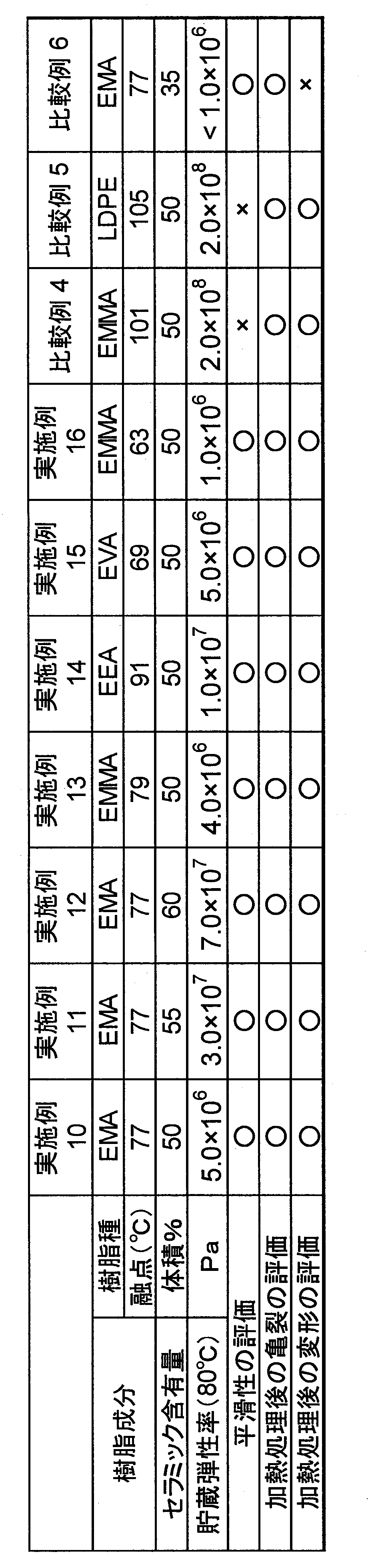
表2に示すように、実施例10~7によれば、動的粘弾性(DMA)測定において、振動周波数が1Hzであり、80℃における貯蔵弾性率(E’)がいずれも1.0×10⁸Pa以下であった。
また、いずれもプレス工程時に凹凸を平滑化することができることを確認した。
さらに、加熱処理後において、亀裂および変形が少ないことを確認した。
これに対して、比較例4及び比較例5では、樹脂成分の融点が100℃以上であり、平滑性が十分ではないことを確認した。
また、比較例6では、無機物の含有量が40体積%未満であり、加熱処理後に大きな変形が生じることを確認した。
本発明の第一実施形態に係る樹脂シート及び積層樹脂シートは、セラミックグリーンシートと内部電極が交互に多数積み重ねられた構造を有する、チップ化された積層体等の、表面保護材として利用可能である。
さらに本発明の第二実施形態に係る樹脂組成物及び樹脂シートは、積層セラミックコンデンサを製造する際に、セラミックグリーンシートの表面保護材として利用可能性を有する。
1,2・・・積層樹脂シート
11・・・第1樹脂シート
12・・・第2樹脂シート
13・・・第3樹脂シート
Claims (17)
- 溝を埋め込み処理するための樹脂シートであって、
前記溝は、深さ/幅の比が0.5以上であり、
処理対象物の前記溝を有する表面上に、前記溝を覆うように前記樹脂シートを配置し、温度190℃、圧力92kg/cm2の条件で、前記樹脂シートを前記処理対象物に対して加熱しながら押圧したときに、前記溝に陥入して、前記溝を埋め込み可能である、樹脂シート。 - 温度80℃、せん断速度7.6s-1の条件下での粘度V5が1500kPa・s以下であり、溝を埋め込み処理するための樹脂シートであって、
前記溝は、深さ/幅の比が0.5以上であり、
処理対象物の前記溝を有する表面上に、前記溝を覆うように前記樹脂シートを配置し、温度80℃、圧力92kg/cm2の条件で、前記樹脂シートを前記処理対象物に対して加熱しながら押圧したときに、前記溝に陥入して、前記溝を埋め込み可能である、樹脂シート。 - 第1樹脂成分及び無機物を含有する第1樹脂シートと、
第2樹脂成分を含有する第2樹脂シートと、が積層され、
温度80℃、せん断速度7.6s-1の条件下での、第1樹脂シートの粘度をV1kPa・s、第2樹脂シートの粘度をV2kPa・sとしたときに、Log(V2)/Log(V1)が0.7~1.4である、積層樹脂シート。 - 前記第1樹脂成分の融点又はガラス転移温度が100℃未満であり、
前記第1樹脂シートの前記無機物の含有量が40体積%以上である、請求項3に記載の積層樹脂シート。 - 前記第1樹脂成分が、エチレン-酢酸ビニル共重合体、エチレン-(メタ)アクリル酸共重合体、エチレン-(メタ)アクリル酸メチル共重合体及びエチレン-アクリル酸エチル共重合体からなる群より選択される1種又は2種以上のエチレン系共重合体を含む、請求項3又は4に記載の積層樹脂シート。
- 前記無機物が、チタン酸バリウム、チタン酸ストロンチウム及びジルコン酸チタン酸鉛からなる群より選択される1種又は2種以上の誘電体セラミックを含む、請求項3~5のいずれか一項に記載の積層樹脂シート。
- 前記V2が1500kPa・s以下である、請求項3~6のいずれか一項に記載の積層樹脂シート。
- 前記V1が1500kPa・s以下である、請求項3~7のいずれか一項に記載の積層樹脂シート。
- 前記第1樹脂シートの比誘電率が15以上である、請求項3~8のいずれか一項に記載の積層樹脂シート。
- 前記第1樹脂シートの厚さが10~200μmである、請求項3~9のいずれか一項に記載の積層樹脂シート。
- 前記第2樹脂シートの厚さが20~1000μmである、請求項3~10のいずれか一項に記載の積層樹脂シート。
- 前記第2樹脂シートの、前記第1樹脂シートが積層されている側とは反対側に、さらに1以上の樹脂シートが積層された、請求項3~11のいずれか一項に記載の積層樹脂シート。
- 融点又はガラス転移温度が100℃未満の樹脂成分と、無機物を含有し、前記無機物の含有量が40体積%以上である、樹脂シート。
- 前記無機物が、誘電体セラミックである、請求項13に記載の樹脂組成物。
- 前記樹脂成分が、エチレン系共重合体を含む、請求項13又は14に記載の樹脂組成物。
- 動的粘弾性(DMA)測定において、振動周波数が10Hzであり、80℃における貯蔵弾性率が1.0×10⁸Pa以下である、請求項13乃至15のいずれか一項に記載の樹脂組成物。
- 厚さが1μm以上である、請求項13に記載の樹脂シート。
Priority Applications (1)
| Application Number | Priority Date | Filing Date | Title |
|---|---|---|---|
| JP2018557051A JP6540913B2 (ja) | 2017-03-15 | 2018-03-12 | 樹脂シート、積層樹脂シート、および樹脂組成物 |
Applications Claiming Priority (4)
| Application Number | Priority Date | Filing Date | Title |
|---|---|---|---|
| JP2017-050585 | 2017-03-15 | ||
| JP2017050585 | 2017-03-15 | ||
| JP2017122906 | 2017-06-23 | ||
| JP2017-122906 | 2017-06-23 |
Publications (1)
| Publication Number | Publication Date |
|---|---|
| WO2018168758A1 true WO2018168758A1 (ja) | 2018-09-20 |
Family
ID=63523080
Family Applications (1)
| Application Number | Title | Priority Date | Filing Date |
|---|---|---|---|
| PCT/JP2018/009483 Ceased WO2018168758A1 (ja) | 2017-03-15 | 2018-03-12 | 樹脂シート、積層樹脂シート、および樹脂組成物 |
Country Status (3)
| Country | Link |
|---|---|
| JP (1) | JP6540913B2 (ja) |
| TW (1) | TW201842008A (ja) |
| WO (1) | WO2018168758A1 (ja) |
Cited By (1)
| Publication number | Priority date | Publication date | Assignee | Title |
|---|---|---|---|---|
| JP2019009266A (ja) * | 2017-06-23 | 2019-01-17 | 株式会社村田製作所 | 積層セラミック電子部品の製造方法、及び、積層セラミック電子部品 |
Citations (8)
| Publication number | Priority date | Publication date | Assignee | Title |
|---|---|---|---|---|
| JPS5943039A (ja) * | 1982-09-03 | 1984-03-09 | Kureha Chem Ind Co Ltd | 誘電体フイルム |
| JPS63264671A (ja) * | 1986-12-27 | 1988-11-01 | Yobea Rulon Kogyo Kk | 高誘電率樹脂組成物 |
| JPH0384993A (ja) * | 1989-08-29 | 1991-04-10 | Taiyo Yuden Co Ltd | セラミック積層板の分割方法 |
| JP2000159577A (ja) * | 1998-09-22 | 2000-06-13 | Tdk Corp | セラミック基板の製造方法 |
| JP2004253608A (ja) * | 2003-02-20 | 2004-09-09 | Teijin Ltd | 誘電体形成用多孔質シートの熱圧着、積層方法 |
| JP2006043073A (ja) * | 2004-08-04 | 2006-02-16 | Sankyo Giken Kk | 浴槽の中蓋およびその製造方法 |
| JP2007294114A (ja) * | 2006-04-20 | 2007-11-08 | Polymatech Co Ltd | キーシート |
| JP2012059743A (ja) * | 2010-09-06 | 2012-03-22 | Nitto Denko Corp | 電子部品装置の製法およびそれに用いる電子部品封止用樹脂組成物シート |
Family Cites Families (3)
| Publication number | Priority date | Publication date | Assignee | Title |
|---|---|---|---|---|
| JPS61122152A (ja) * | 1984-11-20 | 1986-06-10 | 宇部興産株式会社 | 射出成形用セラミツク組成物 |
| JPS62241863A (ja) * | 1986-04-08 | 1987-10-22 | 日産自動車株式会社 | 射出成形用材料 |
| JPH02119164A (ja) * | 1989-09-20 | 1990-05-07 | Hitachi Ltd | 半導体モジユール |
-
2018
- 2018-03-06 TW TW107107341A patent/TW201842008A/zh unknown
- 2018-03-12 WO PCT/JP2018/009483 patent/WO2018168758A1/ja not_active Ceased
- 2018-03-12 JP JP2018557051A patent/JP6540913B2/ja not_active Expired - Fee Related
Patent Citations (8)
| Publication number | Priority date | Publication date | Assignee | Title |
|---|---|---|---|---|
| JPS5943039A (ja) * | 1982-09-03 | 1984-03-09 | Kureha Chem Ind Co Ltd | 誘電体フイルム |
| JPS63264671A (ja) * | 1986-12-27 | 1988-11-01 | Yobea Rulon Kogyo Kk | 高誘電率樹脂組成物 |
| JPH0384993A (ja) * | 1989-08-29 | 1991-04-10 | Taiyo Yuden Co Ltd | セラミック積層板の分割方法 |
| JP2000159577A (ja) * | 1998-09-22 | 2000-06-13 | Tdk Corp | セラミック基板の製造方法 |
| JP2004253608A (ja) * | 2003-02-20 | 2004-09-09 | Teijin Ltd | 誘電体形成用多孔質シートの熱圧着、積層方法 |
| JP2006043073A (ja) * | 2004-08-04 | 2006-02-16 | Sankyo Giken Kk | 浴槽の中蓋およびその製造方法 |
| JP2007294114A (ja) * | 2006-04-20 | 2007-11-08 | Polymatech Co Ltd | キーシート |
| JP2012059743A (ja) * | 2010-09-06 | 2012-03-22 | Nitto Denko Corp | 電子部品装置の製法およびそれに用いる電子部品封止用樹脂組成物シート |
Cited By (1)
| Publication number | Priority date | Publication date | Assignee | Title |
|---|---|---|---|---|
| JP2019009266A (ja) * | 2017-06-23 | 2019-01-17 | 株式会社村田製作所 | 積層セラミック電子部品の製造方法、及び、積層セラミック電子部品 |
Also Published As
| Publication number | Publication date |
|---|---|
| JP6540913B2 (ja) | 2019-07-10 |
| TW201842008A (zh) | 2018-12-01 |
| JPWO2018168758A1 (ja) | 2019-03-22 |
Similar Documents
| Publication | Publication Date | Title |
|---|---|---|
| TWI534009B (zh) | 成形體,顯示器之前蓋材及影像顯示裝置 | |
| CN105008480B (zh) | 导热性薄片 | |
| EP3533849A1 (en) | Dielectric-heating bonding film and bonding method using dielectric-heating bonding film | |
| KR20110085991A (ko) | 열전도 시트, 그 제조방법 및 이것을 이용한 방열 장치 | |
| CN111655648B (zh) | 夹层玻璃用中间膜和夹层玻璃 | |
| WO2016198425A1 (en) | High thermally conductive low pressure mouldable hotmelt | |
| CN113165333B (zh) | 含有增滑剂的多层膜和层压件 | |
| US10825610B2 (en) | Method for producing multilayer ceramic electronic component | |
| JP6900800B2 (ja) | 積層セラミック電子部品の製造方法、及び、積層セラミック電子部品 | |
| EP3228450B1 (en) | Thermal conducting sheet and method for producing same | |
| WO2017199985A1 (ja) | 接着剤、接着性樹脂組成物及びこれよりなる積層体 | |
| JP6935687B2 (ja) | 積層セラミック電子部品の製造方法 | |
| CN104870190A (zh) | 含有官能性乙烯基聚合物组合物的多层膜 | |
| JP6944708B2 (ja) | 熱伝導エラストマー組成物、及び熱伝導成形体 | |
| TWI586545B (zh) | Laminated body | |
| JPWO2018168758A1 (ja) | 樹脂シート、積層樹脂シート、および樹脂組成物 | |
| JP2019182925A (ja) | 樹脂組成物、及び樹脂シート | |
| CN110730719A (zh) | 含有助滑剂的多层薄膜和层合物 | |
| JP6359243B2 (ja) | 表面保護フィルム | |
| JP2003246019A (ja) | 離型フィルム及びカバーレイ成形方法 | |
| JP2024114225A (ja) | 配線基板用接着シート、配線基板用積層体および配線基板 | |
| JP2020139063A (ja) | 樹脂組成物、及び樹脂シート | |
| KR20120019594A (ko) | 인쇄회로기판용 이형필름 | |
| KR102465161B1 (ko) | 방열 시트, 이의 제조방법 및 이를 포함하는 전자기기 | |
| JP2014213542A (ja) | 表面保護フィルム |
Legal Events
| Date | Code | Title | Description |
|---|---|---|---|
| ENP | Entry into the national phase |
Ref document number: 2018557051 Country of ref document: JP Kind code of ref document: A |
|
| 121 | Ep: the epo has been informed by wipo that ep was designated in this application |
Ref document number: 18767719 Country of ref document: EP Kind code of ref document: A1 |
|
| NENP | Non-entry into the national phase |
Ref country code: DE |
|
| 122 | Ep: pct application non-entry in european phase |
Ref document number: 18767719 Country of ref document: EP Kind code of ref document: A1 |