WO2018168564A1 - Drone for measuring water depth of field - Google Patents
Drone for measuring water depth of field Download PDFInfo
- Publication number
- WO2018168564A1 WO2018168564A1 PCT/JP2018/008490 JP2018008490W WO2018168564A1 WO 2018168564 A1 WO2018168564 A1 WO 2018168564A1 JP 2018008490 W JP2018008490 W JP 2018008490W WO 2018168564 A1 WO2018168564 A1 WO 2018168564A1
- Authority
- WO
- WIPO (PCT)
- Prior art keywords
- drone
- field
- water depth
- water
- sensor
- Prior art date
- Legal status (The legal status is an assumption and is not a legal conclusion. Google has not performed a legal analysis and makes no representation as to the accuracy of the status listed.)
- Ceased
Links
Images


Classifications
-
- G—PHYSICS
- G01—MEASURING; TESTING
- G01C—MEASURING DISTANCES, LEVELS OR BEARINGS; SURVEYING; NAVIGATION; GYROSCOPIC INSTRUMENTS; PHOTOGRAMMETRY OR VIDEOGRAMMETRY
- G01C13/00—Surveying specially adapted to open water, e.g. sea, lake, river or canal
- G01C13/008—Surveying specially adapted to open water, e.g. sea, lake, river or canal measuring depth of open water
-
- B—PERFORMING OPERATIONS; TRANSPORTING
- B64—AIRCRAFT; AVIATION; COSMONAUTICS
- B64U—UNMANNED AERIAL VEHICLES [UAV]; EQUIPMENT THEREFOR
- B64U10/00—Type of UAV
- B64U10/10—Rotorcrafts
- B64U10/13—Flying platforms
-
- G—PHYSICS
- G01—MEASURING; TESTING
- G01C—MEASURING DISTANCES, LEVELS OR BEARINGS; SURVEYING; NAVIGATION; GYROSCOPIC INSTRUMENTS; PHOTOGRAMMETRY OR VIDEOGRAMMETRY
- G01C25/00—Manufacturing, calibrating, cleaning, or repairing instruments or devices referred to in the other groups of this subclass
- G01C25/005—Manufacturing, calibrating, cleaning, or repairing instruments or devices referred to in the other groups of this subclass initial alignment, calibration or starting-up of inertial devices
-
- G—PHYSICS
- G01—MEASURING; TESTING
- G01C—MEASURING DISTANCES, LEVELS OR BEARINGS; SURVEYING; NAVIGATION; GYROSCOPIC INSTRUMENTS; PHOTOGRAMMETRY OR VIDEOGRAMMETRY
- G01C9/00—Measuring inclination, e.g. by clinometers, by levels
- G01C9/005—Measuring inclination, e.g. by clinometers, by levels specially adapted for use in aircraft
-
- G—PHYSICS
- G01—MEASURING; TESTING
- G01S—RADIO DIRECTION-FINDING; RADIO NAVIGATION; DETERMINING DISTANCE OR VELOCITY BY USE OF RADIO WAVES; LOCATING OR PRESENCE-DETECTING BY USE OF THE REFLECTION OR RERADIATION OF RADIO WAVES; ANALOGOUS ARRANGEMENTS USING OTHER WAVES
- G01S13/00—Systems using the reflection or reradiation of radio waves, e.g. radar systems; Analogous systems using reflection or reradiation of waves whose nature or wavelength is irrelevant or unspecified
- G01S13/02—Systems using reflection of radio waves, e.g. primary radar systems; Analogous systems
- G01S13/06—Systems determining position data of a target
- G01S13/08—Systems for measuring distance only
-
- G—PHYSICS
- G01—MEASURING; TESTING
- G01S—RADIO DIRECTION-FINDING; RADIO NAVIGATION; DETERMINING DISTANCE OR VELOCITY BY USE OF RADIO WAVES; LOCATING OR PRESENCE-DETECTING BY USE OF THE REFLECTION OR RERADIATION OF RADIO WAVES; ANALOGOUS ARRANGEMENTS USING OTHER WAVES
- G01S15/00—Systems using the reflection or reradiation of acoustic waves, e.g. sonar systems
- G01S15/02—Systems using the reflection or reradiation of acoustic waves, e.g. sonar systems using reflection of acoustic waves
- G01S15/06—Systems determining the position data of a target
- G01S15/08—Systems for measuring distance only
- G01S15/32—Systems for measuring distance only using transmission of continuous waves, whether amplitude-, frequency-, or phase-modulated, or unmodulated
- G01S15/36—Systems for measuring distance only using transmission of continuous waves, whether amplitude-, frequency-, or phase-modulated, or unmodulated with phase comparison between the received signal and the contemporaneously transmitted signal
-
- G—PHYSICS
- G01—MEASURING; TESTING
- G01S—RADIO DIRECTION-FINDING; RADIO NAVIGATION; DETERMINING DISTANCE OR VELOCITY BY USE OF RADIO WAVES; LOCATING OR PRESENCE-DETECTING BY USE OF THE REFLECTION OR RERADIATION OF RADIO WAVES; ANALOGOUS ARRANGEMENTS USING OTHER WAVES
- G01S15/00—Systems using the reflection or reradiation of acoustic waves, e.g. sonar systems
- G01S15/88—Sonar systems specially adapted for specific applications
-
- G—PHYSICS
- G01—MEASURING; TESTING
- G01S—RADIO DIRECTION-FINDING; RADIO NAVIGATION; DETERMINING DISTANCE OR VELOCITY BY USE OF RADIO WAVES; LOCATING OR PRESENCE-DETECTING BY USE OF THE REFLECTION OR RERADIATION OF RADIO WAVES; ANALOGOUS ARRANGEMENTS USING OTHER WAVES
- G01S17/00—Systems using the reflection or reradiation of electromagnetic waves other than radio waves, e.g. lidar systems
- G01S17/02—Systems using the reflection of electromagnetic waves other than radio waves
- G01S17/06—Systems determining position data of a target
- G01S17/08—Systems determining position data of a target for measuring distance only
- G01S17/32—Systems determining position data of a target for measuring distance only using transmission of continuous waves, whether amplitude-, frequency-, or phase-modulated, or unmodulated
- G01S17/36—Systems determining position data of a target for measuring distance only using transmission of continuous waves, whether amplitude-, frequency-, or phase-modulated, or unmodulated with phase comparison between the received signal and the contemporaneously transmitted signal
-
- G—PHYSICS
- G01—MEASURING; TESTING
- G01S—RADIO DIRECTION-FINDING; RADIO NAVIGATION; DETERMINING DISTANCE OR VELOCITY BY USE OF RADIO WAVES; LOCATING OR PRESENCE-DETECTING BY USE OF THE REFLECTION OR RERADIATION OF RADIO WAVES; ANALOGOUS ARRANGEMENTS USING OTHER WAVES
- G01S17/00—Systems using the reflection or reradiation of electromagnetic waves other than radio waves, e.g. lidar systems
- G01S17/88—Lidar systems specially adapted for specific applications
-
- G—PHYSICS
- G01—MEASURING; TESTING
- G01S—RADIO DIRECTION-FINDING; RADIO NAVIGATION; DETERMINING DISTANCE OR VELOCITY BY USE OF RADIO WAVES; LOCATING OR PRESENCE-DETECTING BY USE OF THE REFLECTION OR RERADIATION OF RADIO WAVES; ANALOGOUS ARRANGEMENTS USING OTHER WAVES
- G01S7/00—Details of systems according to groups G01S13/00, G01S15/00, G01S17/00
- G01S7/52—Details of systems according to groups G01S13/00, G01S15/00, G01S17/00 of systems according to group G01S15/00
- G01S7/52004—Means for monitoring or calibrating
- G01S7/52006—Means for monitoring or calibrating with provision for compensating the effects of temperature
-
- B—PERFORMING OPERATIONS; TRANSPORTING
- B64—AIRCRAFT; AVIATION; COSMONAUTICS
- B64U—UNMANNED AERIAL VEHICLES [UAV]; EQUIPMENT THEREFOR
- B64U2101/00—UAVs specially adapted for particular uses or applications
- B64U2101/40—UAVs specially adapted for particular uses or applications for agriculture or forestry operations
-
- B—PERFORMING OPERATIONS; TRANSPORTING
- B64—AIRCRAFT; AVIATION; COSMONAUTICS
- B64U—UNMANNED AERIAL VEHICLES [UAV]; EQUIPMENT THEREFOR
- B64U30/00—Means for producing lift; Empennages; Arrangements thereof
- B64U30/20—Rotors; Rotor supports
- B64U30/24—Coaxial rotors
-
- B—PERFORMING OPERATIONS; TRANSPORTING
- B64—AIRCRAFT; AVIATION; COSMONAUTICS
- B64U—UNMANNED AERIAL VEHICLES [UAV]; EQUIPMENT THEREFOR
- B64U30/00—Means for producing lift; Empennages; Arrangements thereof
- B64U30/20—Rotors; Rotor supports
- B64U30/26—Ducted or shrouded rotors
-
- G—PHYSICS
- G01—MEASURING; TESTING
- G01S—RADIO DIRECTION-FINDING; RADIO NAVIGATION; DETERMINING DISTANCE OR VELOCITY BY USE OF RADIO WAVES; LOCATING OR PRESENCE-DETECTING BY USE OF THE REFLECTION OR RERADIATION OF RADIO WAVES; ANALOGOUS ARRANGEMENTS USING OTHER WAVES
- G01S15/00—Systems using the reflection or reradiation of acoustic waves, e.g. sonar systems
- G01S15/86—Combinations of sonar systems with lidar systems; Combinations of sonar systems with systems not using wave reflection
-
- G—PHYSICS
- G01—MEASURING; TESTING
- G01S—RADIO DIRECTION-FINDING; RADIO NAVIGATION; DETERMINING DISTANCE OR VELOCITY BY USE OF RADIO WAVES; LOCATING OR PRESENCE-DETECTING BY USE OF THE REFLECTION OR RERADIATION OF RADIO WAVES; ANALOGOUS ARRANGEMENTS USING OTHER WAVES
- G01S17/00—Systems using the reflection or reradiation of electromagnetic waves other than radio waves, e.g. lidar systems
- G01S17/86—Combinations of lidar systems with systems other than lidar, radar or sonar, e.g. with direction finders
Definitions
- the present invention relates to a drone for measuring the water depth of a field using an unmanned air vehicle (drone).
- drone unmanned air vehicle
- Maintaining the water level in the field is extremely important in the cultivation of rice and other crops. For example, when spraying the herbicide, it takes about one week until an appropriate treatment layer is formed, but if the ground is exposed from the water surface in part of the field during that time, the treatment layer is not formed, The effect of the herbicide cannot be obtained. In order to prevent such a situation, it is indispensable to manage the water level in the entire field.
- Patent Document 1 A method of using a number of depth gauges for one field is known (for example, Patent Document 1), but there are problems in terms of cost and management load.
- a simple device capable of accurately measuring the water depth of a farm field, particularly the whole rice field.
- the present invention comprises a first sensor that measures the distance to the water surface and a second sensor that measures the distance to the ground, and measures the water depth at a point directly below the aircraft by taking the difference between the two distances.
- this invention respond
- the present invention further provides the unmanned aerial vehicle according to Paragraph 0006 or Paragraph 0007, further including a tilt sensor and means for correcting a distance measured according to the tilt of the aircraft.
- Paragraph 0006 or Paragraph 0007 further including a tilt sensor and means for correcting a distance measured according to the tilt of the aircraft.
- the first sensor is an ultrasonic transmitter / receiver
- the second sensor is an infrared transmitter / receiver or a microwave transmitter / receiver, according to Paragraph 0006, Paragraph 0007, or Paragraph 0008.
- the above problem is addressed by providing an unmanned air vehicle.
- FIG. 1 shows the overall structure of a drone (100) according to the present invention
- FIG. 1a is a plan view and FIG. 1b is a front view
- “drone” refers to all unmanned aerial vehicles regardless of a driving method or a control method.
- the rotor (101) and the motor (102) are means for flying the drone.
- a drone (100) according to the present invention includes a computer device and program for controlling flight and calculating and storing water depth, wireless communication means for remote control, a GPS device for position detection, and a battery It is desirable to be provided, but not shown.
- the drone (100) preferably includes means capable of accurately measuring the position of the own device such as RTK-GPS.
- the ultrasonic transceiver (103) and an infrared transceiver (104) are provided in the lower part of the drone (100) according to the present invention.
- the ultrasonic transceiver (103) is an example of means for measuring the distance to the water surface
- the infrared transceiver (104) is an example of means for measuring the distance to the ground below the water surface.
- a microwave transceiver or the like may be used instead of the infrared transceiver (104).
- the ultrasonic transmitter / receiver (103) preferably uses a sensor having a frequency of about 400 kHz (a frequency of at least 100 kHz) in order to improve measurement accuracy at a short distance.
- the infrared transmitter / receiver uses near infrared rays having a wavelength of several micrometers, and preferably uses a laser in order to reduce attenuation.
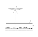
- FIG. 2 shows the basic concept of the field water depth measurement method according to the present invention. Since the ultrasonic waves generated by the ultrasonic transceiver (103) are mainly reflected on the water surface (201), the distance from the drone (100) to the water surface can be measured by measuring the phase difference of the reflected waves. . By using an ultrasonic transmitter / receiver that is generally available at the time of filing, measurement in units of 1 centimeter is possible. Since the sound speed varies depending on the temperature, the air speed may be corrected by providing the drone (100) with a temperature sensor or the like to measure the air temperature.
- the drone (100) at that time The inventor's experiment has revealed that the depth of water at a point in the field immediately below can be measured in units of about 1 centimeter.
- the measurement of the water depth by the field water depth measurement drone (100) can eliminate the influence of the wind of the rotor blade (101).
- a drone is lifted and moved by a downward airflow generated by a rotor blade. Therefore, it is necessary to eliminate the influence of the airflow on the water surface.
- the drone (100) is moving at a normal flight speed (typically 5 meters per second)
- the turbulence of the water surface (201) due to the airflow (301) of the rotor blades is just below the drone (100) fuselage. It occurs behind (opposite the direction of travel).
- the measurement of the distance to the water surface by the ultrasonic transmitter / receiver (103) is performed directly under the drone (100) body, and thus is not affected by the disturbance of the water surface.
- the measurement of the distance to the surface is affected by turbulence in the surface. It has been clarified by experiments by the inventors that there is no such thing.
- the depth measurement according to the present invention is performed only when the drone (100) is flying at a steady speed (for example, about 5 meters per second), and when hovering or at a low speed (for example, about 3 meters or less per second).
- the drone (100) moves by increasing the rotational speed of the rotor blades behind the traveling direction rather than the rotational speed of the rotor blades ahead of the traveling direction, the front of the aircraft in the traveling direction becomes lower during the movement. Inclination occurs. Therefore, the drone (100) according to the present invention is provided with means for measuring the inclination of the airframe such as a gyro sensor, and the ultrasonic transceiver (103) and the infrared transceiver (104) in the program for measuring and storing the distance. It is preferable to correct the distance measured in (1).
- the drone (100) equipped with accurate own position measurement means such as RTK-GPS it is possible to fly the drone (100) all over the field. Therefore, the water depth of the entire field can be easily measured by the water depth measurement drone (100) according to the present invention.
- operations such as drug spraying and crop photography in the field may be performed. It is preferable to store the measured water depth in the entire field in the drone (100) main body or in the memory of a device connected to the drone (100) and input the water depth management work.
- the depth of water in the entire field can be measured efficiently and accurately without using a large number of depth gauges.
Landscapes
- Engineering & Computer Science (AREA)
- Remote Sensing (AREA)
- Radar, Positioning & Navigation (AREA)
- Physics & Mathematics (AREA)
- General Physics & Mathematics (AREA)
- Computer Networks & Wireless Communication (AREA)
- Aviation & Aerospace Engineering (AREA)
- Electromagnetism (AREA)
- Life Sciences & Earth Sciences (AREA)
- Hydrology & Water Resources (AREA)
- Mechanical Engineering (AREA)
- Acoustics & Sound (AREA)
- Manufacturing & Machinery (AREA)
- Measurement Of Velocity Or Position Using Acoustic Or Ultrasonic Waves (AREA)
Abstract
Description
本願発明は、無人飛行体(ドローン)を使用した圃場の水深を測定するためのドローンに関する。 The present invention relates to a drone for measuring the water depth of a field using an unmanned air vehicle (drone).
稲をはじめとした作物の育成において圃場の水位の維持はきわめて重要である。たとえば、除草剤を散布する際には適切な処理層が形成されるまでにおよそ1週間を要するが、その間に圃場の一部で水面から地面が露出してしまうと処理層が形成されず、除草剤の効果が得られなくなってしまう。このような状況を防ぐためには圃場の全域における水位の管理が不可欠である。 Maintaining the water level in the field is extremely important in the cultivation of rice and other crops. For example, when spraying the herbicide, it takes about one week until an appropriate treatment layer is formed, but if the ground is exposed from the water surface in part of the field during that time, the treatment layer is not formed, The effect of the herbicide cannot be obtained. In order to prevent such a situation, it is indispensable to manage the water level in the entire field.
圃場の水深計測の方法としては、圃場に設置した水深計によることが一般的であった。しかし、圃場の地形には凹凸があり、1箇所の水深計で測定した水深が適切であるからと言って、圃場全体で水位が適切であるとは限らない。ひとつの圃場に対して多数の水深計を使用する方法が知られているが(たとえば、特許文献1)、費用や管理負荷の点で課題があった。 As a method of measuring the water depth in the field, it was common to use a depth meter installed in the field. However, the topography of the field has irregularities, and just because the water depth measured by one depth meter is appropriate, the water level is not always appropriate for the entire field. A method of using a number of depth gauges for one field is known (for example, Patent Document 1), but there are problems in terms of cost and management load.
圃場、特に、田圃全体の水深を正確に測定できる簡便な装置を提供する。 Provided is a simple device capable of accurately measuring the water depth of a farm field, particularly the whole rice field.
本願発明は、水面までの距離を測定する第一のセンサーと地面までの距離を測定する第二のセンサーとを備え、両距離の差を取ることで機体直下にある地点の水深を測定する無人飛行体を提供することで上記課題に対応する。 The present invention comprises a first sensor that measures the distance to the water surface and a second sensor that measures the distance to the ground, and measures the water depth at a point directly below the aircraft by taking the difference between the two distances. The above problem is addressed by providing a flying object.
また、本願発明は、所定の速度以上で移動中のみに前記機体直下にある地点の水深を測定する段落0006に記載の無人飛行体を提供することで上記課題に対応する。 Moreover, this invention respond | corresponds to the said subject by providing the unmanned air vehicle as described in the paragraph 0006 which measures the water depth of the point just under the said body only while moving at the predetermined speed or more.
また、本願発明は、さらに、傾きセンサーを備え、前記機体の傾きに応じて測定した距離を補正する手段を備えた段落0006、または、段落0007に記載の無人飛行体を提供することで上記課題に対応する。 The present invention further provides the unmanned aerial vehicle according to Paragraph 0006 or Paragraph 0007, further including a tilt sensor and means for correcting a distance measured according to the tilt of the aircraft. Corresponding to
また、本願発明は、前記第一のセンサーは超音波送受信機であり、前記第二のセンサーは赤外線送受信機、または、マイクロ波送受信機である段落0006、段落0007、または、段落0008に記載の無人飛行体を提供することで上記課題に対応する。 Further, in the present invention, the first sensor is an ultrasonic transmitter / receiver, and the second sensor is an infrared transmitter / receiver or a microwave transmitter / receiver, according to Paragraph 0006, Paragraph 0007, or Paragraph 0008. The above problem is addressed by providing an unmanned air vehicle.
圃場、特に、田圃の水深を全体的に測定できる簡便な装置が提供される。 There is provided a simple device capable of measuring the water depth of a field, in particular, a field.
以下、図を参照しながら、本願発明を実施するための形態について説明する。図はすべて例示である。 Hereinafter, an embodiment for carrying out the present invention will be described with reference to the drawings. All figures are exemplary.
図1に本願発明に係るドローン(100)の全体構造(図1-aは平面図、図1-bは正面図)を示す。本願明細書では、「ドローン」とは、駆動方法や制御方法を問わず、無人飛行体全般を指すこととする。回転翼(ローター)(101)とモーター(102)は、ドローンを飛行させるための手段である。図では、二段構成のローターを4セット使用した構成が示されているが、ローターの枚数や構成方法はこれとは異なっていてもよい。本願発明に係るドローン(100)には、飛行の制御や水深の計算と保存等を行なうためのコンピューター装置とプログラム、遠隔操縦のための無線通信手段、位置検出のためのGPS装置、および、バッテリー等が備えられていることが望ましいが、図示していない。また、着陸の際に必要な脚部、モーターを維持するためのフレーム、および、回転翼に手が触れることを防ぐための安全フレーム等、一般的なドローンに必要な構成要素は図示しているが、自明であるため特に説明しない。なお、本願発明に係るドローン(100)は、RTK-GPS等の自機の位置を正確に測定できる手段を備えていることが望ましい。 FIG. 1 shows the overall structure of a drone (100) according to the present invention (FIG. 1a is a plan view and FIG. 1b is a front view). In the present specification, “drone” refers to all unmanned aerial vehicles regardless of a driving method or a control method. The rotor (101) and the motor (102) are means for flying the drone. In the figure, a configuration using four sets of two-stage rotors is shown, but the number of rotors and the configuration method may be different. A drone (100) according to the present invention includes a computer device and program for controlling flight and calculating and storing water depth, wireless communication means for remote control, a GPS device for position detection, and a battery It is desirable to be provided, but not shown. In addition, components necessary for general drones such as legs necessary for landing, a frame for maintaining the motor, and a safety frame for preventing the hands from touching the rotor blades are illustrated. However, since it is obvious, it will not be described in particular. Note that the drone (100) according to the present invention preferably includes means capable of accurately measuring the position of the own device such as RTK-GPS.
本願発明に係るドローン(100)の下部には、超音波送受信機(103)と赤外線送受信機(104)が設けられている。超音波送受信機(103)は水面までの距離を測る手段の一例であり、赤外線送受信機(104)は水面下の地面までの距離を測定する手段の一例である。赤外線送受信機(104)の代わりにマイクロ波送受信機等を使用してもよい。超音波送受信機(103)は、近距離での測定精度向上のために400Khz程度の周波数(少なくとも100Khzの周波数)によるセンサーを使用していることが好ましい。赤外線送受信機は波長が数マイクロメートルの近赤外線を使用し、減衰を少なくするためにレーザーを使用することが好ましい。 An ultrasonic transceiver (103) and an infrared transceiver (104) are provided in the lower part of the drone (100) according to the present invention. The ultrasonic transceiver (103) is an example of means for measuring the distance to the water surface, and the infrared transceiver (104) is an example of means for measuring the distance to the ground below the water surface. A microwave transceiver or the like may be used instead of the infrared transceiver (104). The ultrasonic transmitter / receiver (103) preferably uses a sensor having a frequency of about 400 kHz (a frequency of at least 100 kHz) in order to improve measurement accuracy at a short distance. The infrared transmitter / receiver uses near infrared rays having a wavelength of several micrometers, and preferably uses a laser in order to reduce attenuation.
図2に、本願発明に係る圃場水深測定方法の基本的考え方を示す。超音波送受信機(103)が発生する超音波は主に水面(201)上で反射するため、反射波の位相差を計測することで、ドローン(100)から水面までの距離を測定可能である。出願時点で一般入手可能な超音波送受信機を使用することで、1センチメートル単位での測定が可能である。なお、音速は温度によって変化するため、ドローン(100)に設け温度センサー等により気温を測定し、音速の補正を行なってもよい。 FIG. 2 shows the basic concept of the field water depth measurement method according to the present invention. Since the ultrasonic waves generated by the ultrasonic transceiver (103) are mainly reflected on the water surface (201), the distance from the drone (100) to the water surface can be measured by measuring the phase difference of the reflected waves. . By using an ultrasonic transmitter / receiver that is generally available at the time of filing, measurement in units of 1 centimeter is possible. Since the sound speed varies depending on the temperature, the air speed may be corrected by providing the drone (100) with a temperature sensor or the like to measure the air temperature.
一方、赤外線送受信機(104)が発生する赤外線レーザー光の多くは水を貫通し、圃場の地面(202)によって反射される。地面による反射波の位相差を測定することにより、ドローン(100)から圃場の地面の距離を測定できる。 On the other hand, most of the infrared laser light generated by the infrared transceiver (104) penetrates the water and is reflected by the ground (202) in the field. By measuring the phase difference of the reflected wave from the ground, the distance from the drone (100) to the ground of the field can be measured.
超音波受信機(103)によって求めたドローン(100)と水面の距離、および、赤外線送受信機によって求めたドローン(100)と地面との距離の差を取ることで、その時点でドローン(100)の直下にある圃場内の地点の水深を約1センチメートル単位で測定できることが発明者の実験により明らかになっている。 By taking the difference between the distance between the drone (100) obtained by the ultrasonic receiver (103) and the water surface and the distance between the drone (100) obtained by the infrared transceiver and the ground, the drone (100) at that time The inventor's experiment has revealed that the depth of water at a point in the field immediately below can be measured in units of about 1 centimeter.
図3により、本願発明に係る圃場水深測定用ドローン(100)による水深の測定が回転翼(101)の風の影響を排除できることを説明する。一般に、ドローンは回転翼による下方向への気流によって浮上し、移動する。したがって、その気流による水面への影響を排除する必要がある。ドローン(100)が通常の飛行速度(典型的には毎秒5メートル)で移動中の場合には、回転翼の気流(301)による水面(201)の乱れは、ドローン(100)機体の直下ではなく後方(進行方向の反対側)に生じる。超音波送受信機(103)による水面までの距離測定はドローン(100)機体の直下で行なわれるため、水面の乱れによる影響を受けない。たとえば、ローターの半径が70cmのドローン(100)が水面から3メートルの高度を毎秒5メートルの速度で飛行するという典型的な条件下では、水面との距離の測定が水面の乱れにより影響を受けないことが発明者による実験により明らかになっている。この理由により、本願発明に係る水深測定は、ドローン(100)が定常速度(たとえば、毎秒約5メートル)で飛行している時のみに実施し、ホバリング時または低速(たとえば、毎秒約3メートル以下)での飛行時には実施しないような制御を行なうことが望ましい。なお、ドローン(100)は進行方向前方の回転翼の回転速度よりも、進行方向後方の回転翼の回転速度を速めることで移動するため、移動中には機体に進行方向前方が低くなるような傾きが生じる。そのため、本願発明に係るドローン(100)にはジャイロセンサー等の機体の傾きを計測できる手段を設け、距離を測定・保存するプログラム等において、超音波送受信機(103)および赤外線送受信機(104)で測定された距離を補正することが好ましい。 With reference to FIG. 3, it will be described that the measurement of the water depth by the field water depth measurement drone (100) according to the present invention can eliminate the influence of the wind of the rotor blade (101). In general, a drone is lifted and moved by a downward airflow generated by a rotor blade. Therefore, it is necessary to eliminate the influence of the airflow on the water surface. When the drone (100) is moving at a normal flight speed (typically 5 meters per second), the turbulence of the water surface (201) due to the airflow (301) of the rotor blades is just below the drone (100) fuselage. It occurs behind (opposite the direction of travel). The measurement of the distance to the water surface by the ultrasonic transmitter / receiver (103) is performed directly under the drone (100) body, and thus is not affected by the disturbance of the water surface. For example, under a typical condition where a drone (100) with a rotor radius of 70 cm flies at an altitude of 3 meters from the surface at a speed of 5 meters per second, the measurement of the distance to the surface is affected by turbulence in the surface. It has been clarified by experiments by the inventors that there is no such thing. For this reason, the depth measurement according to the present invention is performed only when the drone (100) is flying at a steady speed (for example, about 5 meters per second), and when hovering or at a low speed (for example, about 3 meters or less per second). It is desirable to carry out such control that is not performed during the flight. Since the drone (100) moves by increasing the rotational speed of the rotor blades behind the traveling direction rather than the rotational speed of the rotor blades ahead of the traveling direction, the front of the aircraft in the traveling direction becomes lower during the movement. Inclination occurs. Therefore, the drone (100) according to the present invention is provided with means for measuring the inclination of the airframe such as a gyro sensor, and the ultrasonic transceiver (103) and the infrared transceiver (104) in the program for measuring and storing the distance. It is preferable to correct the distance measured in (1).
RTK-GPSなどの正確な自機位置測定手段を備えたドローン(100)を使用することにより、圃場上空でドローン(100)をくまなく飛行させることが可能である。したがって、本願発明に係る水深測定用ドローン(100)により圃場全域の水深を容易に測定できる。なお、水深測定と並行して薬剤散布や圃場の作物撮影等の作業を行なわせてもよい。測定した圃場全域の水深はドローン(100)本体、または、ドローン(100)と接続された機器のメモリーに保存し、水深管理作業の入力とすることが好ましい。 By using the drone (100) equipped with accurate own position measurement means such as RTK-GPS, it is possible to fly the drone (100) all over the field. Therefore, the water depth of the entire field can be easily measured by the water depth measurement drone (100) according to the present invention. In parallel with the water depth measurement, operations such as drug spraying and crop photography in the field may be performed. It is preferable to store the measured water depth in the entire field in the drone (100) main body or in the memory of a device connected to the drone (100) and input the water depth management work.
(本願発明による技術的に顕著な効果)
本願発明により、多数の水深計を使用することなく、圃場全域の水深を効率的かつ正確に測定可能である。また、水深測定において、ドローンの回転翼による気流の影響を最小化することが可能である。
(Technologically significant effect of the present invention)
According to the present invention, the depth of water in the entire field can be measured efficiently and accurately without using a large number of depth gauges. In addition, in the depth measurement, it is possible to minimize the influence of the airflow caused by the drone rotor blades.
Claims (4)
Priority Applications (3)
| Application Number | Priority Date | Filing Date | Title |
|---|---|---|---|
| JP2019505902A JP6868303B2 (en) | 2017-03-12 | 2018-03-06 | Field water depth measurement drone |
| CN201880017203.8A CN110392819B (en) | 2017-03-12 | 2018-03-06 | Unmanned aerial vehicle for measuring water depth of farm |
| US16/492,840 US20200232794A1 (en) | 2017-03-12 | 2018-06-03 | Drone for Measuring Water Depth of Field |
Applications Claiming Priority (2)
| Application Number | Priority Date | Filing Date | Title |
|---|---|---|---|
| JP2017046845 | 2017-03-12 | ||
| JP2017-046845 | 2017-03-12 |
Publications (1)
| Publication Number | Publication Date |
|---|---|
| WO2018168564A1 true WO2018168564A1 (en) | 2018-09-20 |
Family
ID=63522914
Family Applications (1)
| Application Number | Title | Priority Date | Filing Date |
|---|---|---|---|
| PCT/JP2018/008490 Ceased WO2018168564A1 (en) | 2017-03-12 | 2018-03-06 | Drone for measuring water depth of field |
Country Status (4)
| Country | Link |
|---|---|
| US (1) | US20200232794A1 (en) |
| JP (1) | JP6868303B2 (en) |
| CN (1) | CN110392819B (en) |
| WO (1) | WO2018168564A1 (en) |
Cited By (5)
| Publication number | Priority date | Publication date | Assignee | Title |
|---|---|---|---|---|
| CN112572564A (en) * | 2020-12-21 | 2021-03-30 | 张振斌 | Portable hydrology water resource surveys device |
| WO2021060454A1 (en) * | 2019-09-25 | 2021-04-01 | 株式会社クボタ | Spray assistance system and server |
| US20220049956A1 (en) * | 2020-08-13 | 2022-02-17 | Dong-A University Research Foundation For Industry-Academy Cooperation | Method for water level measurement and method for obtaining 3d water surface spatial information using unmanned aerial vehicle and virtual water control points |
| EP4162234A4 (en) * | 2020-06-07 | 2024-06-26 | Israel Aerospace Industries Ltd. | IMPROVED TARGET LOCATION DETERMINATION |
| JP7752438B1 (en) | 2024-06-06 | 2025-10-10 | 株式会社嶺水 | How to measure bathymetry |
Families Citing this family (8)
| Publication number | Priority date | Publication date | Assignee | Title |
|---|---|---|---|---|
| CN109444860B (en) * | 2018-10-30 | 2023-04-28 | 泰州市计量测试院 | Simulation calibrating device for multi-beam sounding instrument |
| JP7253315B2 (en) * | 2019-01-29 | 2023-04-06 | 株式会社Subaru | Aircraft flight support system, aircraft flight support program and aircraft |
| US11486992B2 (en) * | 2019-11-15 | 2022-11-01 | Stage Lighting Patents, LLC | Rotating range sensor to measure truss vertical height for stage configurations |
| CN113048953A (en) * | 2021-03-24 | 2021-06-29 | 天地伟业技术有限公司 | Unmanned plane and method for monitoring water level, flow velocity and flow |
| CN113390432B (en) * | 2021-07-01 | 2023-04-25 | 北京汽车集团越野车有限公司 | Vehicle river crossing auxiliary method, vehicle-mounted unmanned aerial vehicle and automobile |
| CN113835098B (en) * | 2021-09-16 | 2023-12-12 | 青岛海洋科技中心 | Laser water depth measuring system and method |
| CN115056981B (en) * | 2022-06-01 | 2025-11-11 | 水利部交通运输部国家能源局南京水利科学研究院 | High-precision water depth measuring method of rotor unmanned aerial vehicle |
| CN120740546B (en) * | 2025-09-02 | 2025-12-09 | 江苏菲尔浦物联网有限公司 | Target detection optimization method and system based on multi-source data fusion |
Citations (12)
| Publication number | Priority date | Publication date | Assignee | Title |
|---|---|---|---|---|
| JPS629284A (en) * | 1985-07-06 | 1987-01-17 | Nec Corp | Laser sounding device |
| JPH05293036A (en) * | 1992-04-17 | 1993-11-09 | Rinnai Corp | Setting device of water volume in rice cooker |
| JPH06201435A (en) * | 1992-10-05 | 1994-07-19 | Krohne Messtech Gmbh & Co Kg | Filling-level measuring method for liquid |
| JPH07181255A (en) * | 1993-12-24 | 1995-07-21 | Oki Electric Ind Co Ltd | Ship collision ground-hitting prevention system |
| JPH102779A (en) * | 1996-06-18 | 1998-01-06 | Nippon Denki Ido Tsushin Kk | River-monitoring system |
| JP2000105281A (en) * | 1998-09-29 | 2000-04-11 | Matsushita Electric Ind Co Ltd | Condition detection system |
| JP2001116550A (en) * | 1999-10-15 | 2001-04-27 | Nishimatsu Constr Co Ltd | Underwater depth measuring instrument and depth measuring method |
| JP2008089583A (en) * | 2006-09-07 | 2008-04-17 | Rosemount Tank Radar Ab | Radar/level measurement |
| US20110271752A1 (en) * | 2010-05-06 | 2011-11-10 | Riegl Laser Measurement Systems Gmbh | Laser Hydrography |
| JP2016015628A (en) * | 2014-07-02 | 2016-01-28 | 三菱重工業株式会社 | Indoor monitoring system and mode of structure |
| WO2016082219A1 (en) * | 2014-11-28 | 2016-06-02 | 深圳市大疆创新科技有限公司 | Unmanned aerial vehicle and water sample detection method thereof |
| WO2017000304A1 (en) * | 2015-07-02 | 2017-01-05 | 深圳市大疆创新科技有限公司 | Unmanned aerial vehicle, control system and method therefor, and landing control method for unmanned aerial vehicle |
Family Cites Families (8)
| Publication number | Priority date | Publication date | Assignee | Title |
|---|---|---|---|---|
| JP2009293958A (en) * | 2008-06-02 | 2009-12-17 | Japan Radio Co Ltd | Liquid depth monitoring system |
| PT2705350T (en) * | 2011-06-30 | 2017-07-13 | Univ Colorado Regents | Remote measurement of shallow depths in semi-transparent media |
| CN103744429B (en) * | 2013-02-07 | 2016-05-25 | 山东英特力光通信开发有限公司 | A kind of small-sized depopulated helicopter flight control system |
| KR101693741B1 (en) * | 2014-04-08 | 2017-01-17 | 광주과학기술원 | Apparatuses and methods for determining the debris deposition in a dam |
| JP6007359B2 (en) * | 2015-02-26 | 2016-10-12 | 株式会社テクノスヤシマ | 3D Marker Water Level Meter for Aerial Shooting |
| JP6555781B2 (en) * | 2015-05-29 | 2019-08-07 | 株式会社笑農和 | Water level management system |
| KR101710613B1 (en) * | 2015-10-12 | 2017-02-27 | 한국해양과학기술원 | Real-time wave and current measurement using Waterproof Drone equipped with hydrofoil |
| JP6710114B2 (en) * | 2016-06-21 | 2020-06-17 | 株式会社日立製作所 | Pipeline inspection vehicle and pipeline inspection system using it |
-
2018
- 2018-03-06 CN CN201880017203.8A patent/CN110392819B/en active Active
- 2018-03-06 WO PCT/JP2018/008490 patent/WO2018168564A1/en not_active Ceased
- 2018-03-06 JP JP2019505902A patent/JP6868303B2/en active Active
- 2018-06-03 US US16/492,840 patent/US20200232794A1/en not_active Abandoned
Patent Citations (12)
| Publication number | Priority date | Publication date | Assignee | Title |
|---|---|---|---|---|
| JPS629284A (en) * | 1985-07-06 | 1987-01-17 | Nec Corp | Laser sounding device |
| JPH05293036A (en) * | 1992-04-17 | 1993-11-09 | Rinnai Corp | Setting device of water volume in rice cooker |
| JPH06201435A (en) * | 1992-10-05 | 1994-07-19 | Krohne Messtech Gmbh & Co Kg | Filling-level measuring method for liquid |
| JPH07181255A (en) * | 1993-12-24 | 1995-07-21 | Oki Electric Ind Co Ltd | Ship collision ground-hitting prevention system |
| JPH102779A (en) * | 1996-06-18 | 1998-01-06 | Nippon Denki Ido Tsushin Kk | River-monitoring system |
| JP2000105281A (en) * | 1998-09-29 | 2000-04-11 | Matsushita Electric Ind Co Ltd | Condition detection system |
| JP2001116550A (en) * | 1999-10-15 | 2001-04-27 | Nishimatsu Constr Co Ltd | Underwater depth measuring instrument and depth measuring method |
| JP2008089583A (en) * | 2006-09-07 | 2008-04-17 | Rosemount Tank Radar Ab | Radar/level measurement |
| US20110271752A1 (en) * | 2010-05-06 | 2011-11-10 | Riegl Laser Measurement Systems Gmbh | Laser Hydrography |
| JP2016015628A (en) * | 2014-07-02 | 2016-01-28 | 三菱重工業株式会社 | Indoor monitoring system and mode of structure |
| WO2016082219A1 (en) * | 2014-11-28 | 2016-06-02 | 深圳市大疆创新科技有限公司 | Unmanned aerial vehicle and water sample detection method thereof |
| WO2017000304A1 (en) * | 2015-07-02 | 2017-01-05 | 深圳市大疆创新科技有限公司 | Unmanned aerial vehicle, control system and method therefor, and landing control method for unmanned aerial vehicle |
Cited By (10)
| Publication number | Priority date | Publication date | Assignee | Title |
|---|---|---|---|---|
| WO2021060454A1 (en) * | 2019-09-25 | 2021-04-01 | 株式会社クボタ | Spray assistance system and server |
| JP2021048799A (en) * | 2019-09-25 | 2021-04-01 | 株式会社クボタ | Spray supporting system |
| JP7293070B2 (en) | 2019-09-25 | 2023-06-19 | 株式会社クボタ | Spraying support system |
| US12604795B2 (en) | 2019-09-25 | 2026-04-21 | Kubota Corporation | Spreading support system and server |
| EP4162234A4 (en) * | 2020-06-07 | 2024-06-26 | Israel Aerospace Industries Ltd. | IMPROVED TARGET LOCATION DETERMINATION |
| US20220049956A1 (en) * | 2020-08-13 | 2022-02-17 | Dong-A University Research Foundation For Industry-Academy Cooperation | Method for water level measurement and method for obtaining 3d water surface spatial information using unmanned aerial vehicle and virtual water control points |
| US11841225B2 (en) * | 2020-08-13 | 2023-12-12 | Dong-A University Research Foundation For Industry-Academy Cooperation | Method for water level measurement and method for obtaining 3D water surface spatial information using unmanned aerial vehicle and virtual water control points |
| CN112572564A (en) * | 2020-12-21 | 2021-03-30 | 张振斌 | Portable hydrology water resource surveys device |
| JP7752438B1 (en) | 2024-06-06 | 2025-10-10 | 株式会社嶺水 | How to measure bathymetry |
| JP2025184147A (en) * | 2024-06-06 | 2025-12-18 | 株式会社嶺水 | How to measure bathymetry |
Also Published As
| Publication number | Publication date |
|---|---|
| JP6868303B2 (en) | 2021-05-12 |
| JPWO2018168564A1 (en) | 2020-01-09 |
| US20200232794A1 (en) | 2020-07-23 |
| CN110392819A (en) | 2019-10-29 |
| CN110392819B (en) | 2022-02-01 |
Similar Documents
| Publication | Publication Date | Title |
|---|---|---|
| JP6868303B2 (en) | Field water depth measurement drone | |
| US10988246B2 (en) | Systems and methods for acoustic radiation control | |
| EP3543119B1 (en) | Systems and methods for reducing the propeller noise | |
| CN110007686B (en) | Collision avoidance systems and methods for unmanned aerial vehicles | |
| CN111556986B (en) | Unmanned aerial vehicle, control method thereof and computer readable recording medium | |
| JP6962720B2 (en) | Flight control methods, information processing equipment, programs and recording media | |
| EP3608231A1 (en) | System and method to reduce dve effect on lidar return | |
| CN107077148B (en) | UAV obstacle avoidance control method, flight controller and unmanned aerial vehicle | |
| US20150360794A1 (en) | Rotorcraft having an airspeed sensor located at the top of a tail fin of the rotorcraft | |
| CN103092211B (en) | Unmanned aerial vehicle emergent land method based on guidance of radio and laser | |
| US20170301249A1 (en) | Dynamic Collision-Avoidance System and Method | |
| US9971354B2 (en) | Tail-sitter flight management system | |
| US20100152933A1 (en) | Apparatus and method for unmanned aerial vehicle ground proximity detection, landing and descent | |
| EP3770609B1 (en) | Air data systems | |
| JP6508320B1 (en) | Control system of unmanned aircraft | |
| CN110275541A (en) | Optimized Trajectories for Improved Noise Using Auto-Takeoff | |
| US20170210466A1 (en) | Initial rotor state compensation for a rotorcraft | |
| WO2019189929A1 (en) | Chemical spray drone | |
| JP2019057185A (en) | Flying device, flying method, and program | |
| WO2018094576A1 (en) | Unmanned aerial vehicle control method, flight controller, and unmanned aerial vehicle | |
| EP3460488B1 (en) | Automatic gain control for laser detector | |
| JP2019064280A (en) | Flight device | |
| CN105711847A (en) | Quad-rotor unmanned helicopter take-off, landing and positioning system based on laser positioning technology | |
| FR3085083A1 (en) | Aircraft | |
| RU2013107441A (en) | INTERFERENCE DETECTION SYSTEM FOR LANDING AND TAKEOFF OF A HELICOPTER |
Legal Events
| Date | Code | Title | Description |
|---|---|---|---|
| 121 | Ep: the epo has been informed by wipo that ep was designated in this application |
Ref document number: 18768567 Country of ref document: EP Kind code of ref document: A1 |
|
| ENP | Entry into the national phase |
Ref document number: 2019505902 Country of ref document: JP Kind code of ref document: A |
|
| NENP | Non-entry into the national phase |
Ref country code: DE |
|
| 122 | Ep: pct application non-entry in european phase |
Ref document number: 18768567 Country of ref document: EP Kind code of ref document: A1 |